EP3701103B1 - Flooring system with enhanced flexibility - Google Patents
Flooring system with enhanced flexibility Download PDFInfo
- Publication number
- EP3701103B1 EP3701103B1 EP17790767.2A EP17790767A EP3701103B1 EP 3701103 B1 EP3701103 B1 EP 3701103B1 EP 17790767 A EP17790767 A EP 17790767A EP 3701103 B1 EP3701103 B1 EP 3701103B1
- Authority
- EP
- European Patent Office
- Prior art keywords
- panels
- edge
- locking surface
- upper locking
- recess
- Prior art date
- Legal status (The legal status is an assumption and is not a legal conclusion. Google has not performed a legal analysis and makes no representation as to the accuracy of the status listed.)
- Active
Links
Images


Classifications
-
- E—FIXED CONSTRUCTIONS
- E04—BUILDING
- E04F—FINISHING WORK ON BUILDINGS, e.g. STAIRS, FLOORS
- E04F15/00—Flooring
- E04F15/02—Flooring or floor layers composed of a number of similar elements
- E04F15/02005—Construction of joints, e.g. dividing strips
- E04F15/02033—Joints with beveled or recessed upper edges
-
- E—FIXED CONSTRUCTIONS
- E04—BUILDING
- E04F—FINISHING WORK ON BUILDINGS, e.g. STAIRS, FLOORS
- E04F15/00—Flooring
- E04F15/02—Flooring or floor layers composed of a number of similar elements
- E04F15/02038—Flooring or floor layers composed of a number of similar elements characterised by tongue and groove connections between neighbouring flooring elements
-
- E—FIXED CONSTRUCTIONS
- E04—BUILDING
- E04F—FINISHING WORK ON BUILDINGS, e.g. STAIRS, FLOORS
- E04F15/00—Flooring
- E04F15/02—Flooring or floor layers composed of a number of similar elements
- E04F15/10—Flooring or floor layers composed of a number of similar elements of other materials, e.g. fibrous or chipped materials, organic plastics, magnesite tiles, hardboard, or with a top layer of other materials
- E04F15/102—Flooring or floor layers composed of a number of similar elements of other materials, e.g. fibrous or chipped materials, organic plastics, magnesite tiles, hardboard, or with a top layer of other materials of fibrous or chipped materials, e.g. bonded with synthetic resins
-
- E—FIXED CONSTRUCTIONS
- E04—BUILDING
- E04F—FINISHING WORK ON BUILDINGS, e.g. STAIRS, FLOORS
- E04F15/00—Flooring
- E04F15/02—Flooring or floor layers composed of a number of similar elements
- E04F15/10—Flooring or floor layers composed of a number of similar elements of other materials, e.g. fibrous or chipped materials, organic plastics, magnesite tiles, hardboard, or with a top layer of other materials
- E04F15/107—Flooring or floor layers composed of a number of similar elements of other materials, e.g. fibrous or chipped materials, organic plastics, magnesite tiles, hardboard, or with a top layer of other materials composed of several layers, e.g. sandwich panels
-
- E—FIXED CONSTRUCTIONS
- E04—BUILDING
- E04F—FINISHING WORK ON BUILDINGS, e.g. STAIRS, FLOORS
- E04F2201/00—Joining sheets or plates or panels
- E04F2201/01—Joining sheets, plates or panels with edges in abutting relationship
- E04F2201/0107—Joining sheets, plates or panels with edges in abutting relationship by moving the sheets, plates or panels substantially in their own plane, perpendicular to the abutting edges
-
- E—FIXED CONSTRUCTIONS
- E04—BUILDING
- E04F—FINISHING WORK ON BUILDINGS, e.g. STAIRS, FLOORS
- E04F2201/00—Joining sheets or plates or panels
- E04F2201/01—Joining sheets, plates or panels with edges in abutting relationship
- E04F2201/0138—Joining sheets, plates or panels with edges in abutting relationship by moving the sheets, plates or panels perpendicular to the main plane
-
- E—FIXED CONSTRUCTIONS
- E04—BUILDING
- E04F—FINISHING WORK ON BUILDINGS, e.g. STAIRS, FLOORS
- E04F2201/00—Joining sheets or plates or panels
- E04F2201/03—Undercut connections, e.g. using undercut tongues or grooves
-
- E—FIXED CONSTRUCTIONS
- E04—BUILDING
- E04F—FINISHING WORK ON BUILDINGS, e.g. STAIRS, FLOORS
- E04F2201/00—Joining sheets or plates or panels
- E04F2201/04—Other details of tongues or grooves
- E04F2201/042—Other details of tongues or grooves with grooves positioned on the rear-side of the panel
-
- E—FIXED CONSTRUCTIONS
- E04—BUILDING
- E04F—FINISHING WORK ON BUILDINGS, e.g. STAIRS, FLOORS
- E04F2201/00—Joining sheets or plates or panels
- E04F2201/04—Other details of tongues or grooves
- E04F2201/043—Other details of tongues or grooves with tongues and grooves being formed by projecting or recessed parts of the panel layers
-
- E—FIXED CONSTRUCTIONS
- E04—BUILDING
- E04F—FINISHING WORK ON BUILDINGS, e.g. STAIRS, FLOORS
- E04F2201/00—Joining sheets or plates or panels
- E04F2201/04—Other details of tongues or grooves
- E04F2201/044—Other details of tongues or grooves with tongues or grooves comprising elements which are not manufactured in one piece with the sheets, plates or panels but which are permanently fixedly connected to the sheets, plates or panels, e.g. at the factory
Definitions
- the present invention is directed to a flooring system comprising a plurality of (identical) floor panels which are mechanically connectable to each other along at least one pair of adjacent first and second opposite joint edges.
- the panels comprise locking elements for connecting said panels in both horizontal and vertical direction.
- the (vertical) locking element in the panels is constructed with a (slight) play, so that in the event that two panels have slightly different warp nevertheless can easily and reliably be mechanically connected with each other omitting the need to exert an excess of force to fit the panels.
- WO 01/02669 A1 describes a fastening system for panels, especially for floor panels that are placed on a base and whose edges are provided with holding profiles.
- the holding profiles of a long edge and a holding profile of the opposite edge as well as the holding profiles on the other two short edges of a panel match one another in such a manner that further panels can be fastened to the free edges of one of the placed panels.
- the holding profiles of the long edge of the panels are configured as complementary positive fit profiles and the panels are interconnected by pivoting them to be joined.
- the complementary positive fit profile is provided with a recess opposite the edge of the panel. The other side facing away from the base is beveled so that there is room for the common joint.
- BE 557844 describes inter-connectable panels with according male and female fitting members, which are designed to provide mechanical locking of interconnected panels.
- the fitting members abut against each other in the installed state.
- EP 1 165 906 B1 describes a fastening system for panels, said panels having inter-locking profiles associated with one another, so that the panels are fastenable to one another by a turning joining action.
- One of the faces of the panels has a groove and the opposite face of this panel has a matching projection which, when installed are responsible for the fastening of the panels with each other.
- AT 321529 describes a form fitting groove connection of panels which can be adjoined by joint-turning action.
- warpage which e.g. occurs during storage of these panels, during which the panels are subject to varying external influences such as temperature, humidity and of aging of the materials of the panels.
- the locking members, being integral part of such panels are subject to such slight warpage.
- warp or "warpage” is synonymously understood to the term “flatness”, especially “width flatness” as defined in EN 13329 (2016-07) ("Laminate floor coverings
- the object of the present invention is to eliminate the above drawbacks in flooring panels, providing a new installation system which also makes it possible to easily but still reliably install also slightly warped panels.
- This objective is solved by the flooring system according to claim 1.
- the dependent claims provide advantageous embodiments.
- the principle plane of the floor panel according to the present invention is the visible side of the floor panel when installed, where e.g. a decorative layer is present. Accordingly, the rear side of a floor panel is the invisible side of the floor panel, i.e. the side facing the floor on which the floor panel is installed. The rear side is opposite to the principal plane.
- the sectional plane or the plurality of sectional planes virtually intersects the panel from the first to the second joint edge, which are arranged on opposite sides of the panel.
- the sectional planes are chosen to intersect the first and second joint edge at a right angle.
- the position of the locking surface of the recess with respect to the distance of upper locking surface of the protrusion from the rear side of each panel is determined in this or this plurality of sectional planes.
- the gap formed in between the upper locking surface of the recess and the upper locking surface of the protrusion is greater than or equal to the manufacturing tolerance of the profiles (i.e. the locking strip, locking element, locking groove, recess, upper locking surface of the recess, protrusion and upper locking surface of the protrusion) of the panels, which regularly is 0.05 mm.
- the floor panels have a rectangular or quadratic shape (with respect to a projection on the principle plane).
- different shapes are possible such as hexagonal circumferences.
- preferred floor panels according to the present invention have a rectangular shape with two opposite long and two opposite short edges.
- the above-mentioned adjacent joint edges represent the both short edges of an according rectangular floor panel.
- the locking element engaging with said locking groove in the installed state enables for a horizontal inter-connecting or fixing of installed floor panels of the flooring system.
- the protrusion and the recess being present on the locking element or the locking groove, respectively allow a vertical securing (i.e. in direction of the vertical plane) of installed floor panels.
- a slight play between the respective upper locking surfaces of the protrusion and the recess is present, which can be measured via the position of the respective surfaces of the recess or the protrusion, respectively in vertical direction, e.g. perpendicular from the rear side of each panel in direction to the principal plane of each panels at the same horizontal position which is the position where the protrusion engages the recess of two adjacent (identical) panels in the normal locked state.
- the gap is present in any virtual intersecting plane in the panel as defined above, thus eliminating the third dimension of the panel and any possibly existing warpage of the panel in the (not considered) third dimension. According to the wording of claim 1 thus a circumference of the panel in the defined plane which is perpendicular to the joint edges is defined.
- the above mentioned gap is present over the complete length of the joint edges, when the panels are completely unwarped or have the same degree of warpage along the first and second edges. If one panel has a different degree of warpage along the first and/or second joint edge, compared with a panel with which it is to be installed, however, a partial physical contact of the respective upper locking surfaces of the recess and the protrusion nevertheless is possible.
- the slight play between recess and protrusion therefore contributes to the fact that recess and protrusion not necessarily are in physical contact with each other when two panels are installed. For example, if two completely unwarped panels (i.e. with no warpage along the first and second joined edge to be installed with respect to each other) are installed, a physical gap is present over the complete length of the first and second joined edges. However, if panels with different degree of warpage along the first and second joined edges are installed with each other, an actual physical contact between the recess and the first protrusion can be present, depending on the degree of deviation of the warpage in the panels installed with each other.
- the first case a slight loss in the physical strength of the vertical connection is accepted, since the play between recess and warpage considerably contributes to a better installability of the flooring panels, especially when warpage as described above occurs. In this case, the panels are installable with less force. Due to the fact, that somewhere along the first and second joined edges a physical contact of the protrusion and the recess occurs in this case - since the first and second joined edges are not completely even - no a loss in the quality of the vertical locking occurs in the second case.
- said recess is defined by the upper locking surface falling off from the external edge in direction of the first joint edge and a second edge intersecting with the upper locking surface , wherein the upper locking surface and the second edge preferably form a obtuse angle at said recess, and/or said protrusion is defined by the upper locking surface protruding from the internal edge in direction of the first joint edge and a second edge falling off from the upper locking surface , wherein the upper locking surface (and the second edge preferably form an angle at said protrusion which is smaller than the obtuse angle defining said recess.
- said recess is defined by the upper locking surface falling off from the internal edge in direction of the second joint edge and a second edge intersecting with the upper locking surface, wherein the upper locking surface and the second edge preferably form a obtuse angle at said recess, and/or said protrusion is defined by the upper locking surface protruding from the external edge in direction of the second joint edge and a second edge falling off from the upper locking surface, wherein the upper locking surface and the second edge preferably form an angle at said protrusion which is smaller than the obtuse angle defining said recess.
- the upper locking surface of the recess, the upper locking surface of the protrusion, the second edge of the recess and/or the second edge of the protrusion are straight, wavy or curved, preferably straight.
- the upper locking surface of the recess and the upper locking surface of the protrusion at any given position of the overlap have a minimum distance (gap width) of 0.05 to 2.0 mm, preferably 0.1 to 1.0 mm, especially preferred 0.2 to 0.5 mm, e.g. 0.25 to 0.35 mm.
- the minimum distance refers to the fact that the distance between the upper locking surface of the recess and the upper locking surface of the protrusion can be variable, especially if the edges do e.g. not run parallel.
- the distance of the upper locking surface of the recess and the upper locking surface of the protrusion is constant at any given position of the overlap.
- the upper locking surfaces are straight or planar and have a constant distance from each other over their entire overlap.
- the upper locking surface of the recess and the upper locking surface of the protrusion both are straight and have an angle of 10° to 50°, preferably 20° to 40°, especially preferred 27.5° to 32.5° with respect to the principal plane.
- the above-defined obtuse angle is preferably is in between 100° and 170°, preferably 115 and 155°, especially preferred 130° and 140°.
- the upper locking surface and the second edge of the protrusion form an angle between 80° to 130°, preferably 90° to 120°, especially preferred 100° to 110°.
- said panels are made of a core, a decorative layer and optionally a backing layer, wherein the locking strip and the locking groove are made in the core.
- Exemplary materials of the core are wood or of wood based material such as MDF, HDF, OSB, chipboard; thermoplastic resins such as PVC; mineral-, glass- or rock wool, and/or cement.
- the decorative layer can be made of a decorative paper with an optional abrasion-resistant topping and/or is printed to the core.
- the backing layer preferably is made of paper (counter-draw paper), veneer, cork, rubber, thermoplastic resin and/or a foamed material.
- the locking strip with the locking element is formed in one piece with the panels or provided as separate part which is fixed to the panels at the first joint edges.
- first and/or second joint edges can comprise at least one dust pocket which can be a recess in one or both joint edges.
- the panels according to the present invention can optionally be provided with additional locking elements guaranteeing a vertical locking of two panels with respect to each other.
- additional locking elements preferably are provided in the first and second opposite joint edges.
- the panels are provided with
- the flexible tongue is flexible and resilient such that two panels can be mechanically joined by displacement of said two panels vertically towards each other, while the locking part of the flexible tongue is resiliently displaced horizontally, until said adjacent edges of the two panels are brought into engagement with each other horizontally and the locking part of the flexible tongue is then displaced towards its initial position and against a wall of the second groove.
- the locking part of the flexible tongue protrudes downwardly.
- the panels are bevelled at the adjacent joint edges at the principal plane.
- edges of the panels also can comprise locking elements, which e.g. can encompass a locking strip with a locking protrusion on one of the other edges of the panel and a locking groove, corresponding to this locking strip with the locking element, on the other of the edges of the panel.
- locking elements e.g. can encompass a locking strip with a locking protrusion on one of the other edges of the panel and a locking groove, corresponding to this locking strip with the locking element, on the other of the edges of the panel.
- These additional locking elements preferably can be present on the both long edges of the floor panel, if the panel has rectangular shape.
- Figure 1 shows a view onto a a sectional plane which is perpendicular to the joint edges 2 and 3 of a flooring system made of two panels as known from the prior art.
- the joint edges 2 and 3 proceed into the plane of the figure and are perpendicular to the plane of the figure.
- Two floor panels 1 and 1' are connected at opposite joined edges 2 and 3 which can be the opposite short edges of a rectangular panel.
- Each panel 1 and 1' has a first joined edge 2 and a second joined edge 3 which is aligned opposite the first joined edge 2. Otherwise, the panels 1 and 1' have the identical shape.
- Figure 1 shows parts of the two panels 1 and 1' in the connected state.
- the panels 1 and 1' have a protruding strip 4 which accommodates a locking element 5a.
- the locking strip 4 with the locking element 5a extends beyond the first joined edge 2.
- the floor panels 1 and 1' comprise a locking groove 5b which is aligned on the second joined edge 3, having a shape that the locking element 5a of the first joined edge can engage said locking groove 5b.
- the locking element 5a has an external edge 6a which limits the locking element 5a forming the most remote edge of the locking strip 4 and/or locking element 5a.
- Said external edge 6a accommodates a recess 7 which e.g. can be an undercut in the edge 6a.
- the locking groove 5b has an internal edge 6b, which is the most internal edge of the locking groove 5b. Said edge 6b accommodates a protrusion 8. Recess and protrusion 8 have a shape that they engage with each other in the locked state of the panels 1 and 1'.
- the panels 1 and 1' have a principle plane PP (or synonymously an upper side or visible side) and a rear side RS (or synonymously backing side).
- the panels 1 and 1' preferably encompass a core 9, a decorative layer 10 as well as a backing layer 11.
- the dimension of the panels with respect of the thickness i.e. the dimension from the rear side RS to the principle plane PP.
- a dust pocket 12 can be present in between the first joined edge 2 and the second joined edge 3.
- the recess 7 has an upper locking surface 7' whereas the protrusion 8 has an upper locking surface 8' which are shaped that in the installed state of the panels 1, 1' the overlap in a region OL in order to provide a locking in the vertical direction (this is the direction from the rear side RS to the principal plane PP).
- the respective upper locking surfaces 7' and 8' respectively are so shaped that the installed state a physical contact is guaranteed over the entire area of the locking surfaces 7' and 8'.
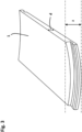
- Figure 2 shows in a schematic manner an unwarped panel 1, having a thickness d. the panel 1 is completely flat or even as can be seen by the dashed lines. Accordingly, the maximum dimension z at the side of the panel where the locking element is present is equal to the thickness d.
- Figure 3 shows a slightly warped panel 1, which otherwise is identical to the panel as displayed in Figure 2 .
- the panel has a slight curvature at the short side, where the locking element is present (displayed in the foreground).
- the maximum dimension z of the panel (being the difference of the highest point of the principle plane of the panel and the lowest point of the rear side of the panel) is bigger than the thickness d of the panel which can be measured at the other edge (in this case the long edge).
- This warpage likely occurs when the panels partly are fully made of natural materials, such as wood etc., and are due to the fact that these materials alter their dimensions with varying of external factors such as temperature, moisture, water content or age.
- the locking elements such as shown in Figure 1 are fully form-fitting (i.e. that the upper locking surfaces 7' and 8' are designed to be in complete form-fit with each other so that no gap is present between them), the installation of warped panels as displayed in Figure 3 with panels having a different degree of warpage (i.e. panels in which the ratio z/d is different) becomes disturbed or even impossible.
- enhanced mechanical force is needed in order to properly install such differently warped panels. A damaging or even destruction of the locking elements thus is possible, making the panels in the worst case not suitable for a proper installation.
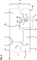
- Figure 4 displays a view onto a a sectional plane which is perpendicular to the joint edges 2 and 3 of a flooring system according to the present invention. Again, the joint edges 2 and 3 proceed into the plane of the figure and are perpendicular to the plane of the figure.
- the panels 1 and 1' have almost identical shape as Figure 1 .
- the same numerals depict the same elements. In order to avoid repetitions only the differences of the flooring system according to Figure 4 with respect to the flooring system according to Figure 1 will be discussed in the following. All not mentioned elements are the same as in Figure 1 .
- each panel 1, 1' is designed that at any sectional or slice plane perpendicular to the first or second joint edges 2 and 3 at any given position of the overlap OL the upper locking surface 7' of the recess 7 is distanced further from the rear side RS than the upper locking surface 8' of the protrusion 8 to form a gap G.
- each panel 1, 1' enables that a gap G ia or at least can be present in between the recess 7 and the protrusion 8 or the respective locking surfaces 7' and 8' thereof when the panels are mechanically joined, i.e. a (slight) play in the vertical locking element of the panels is given.
- This play contributes to a better installability of two panels 1 and 1', especially if the panels show different degrees of warpage as displayed in Figure 3 . Less force is needed to install the panels with respect to each other, without being detrimental to the vertical locking function.
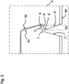
- Figure 5 describes or displays an enlarged view of the dashed box A in Figure 4 .
- the recess 7 is defined by an intersection of the upper locking surface 7' 7' and a second edge or surface 7".
- the upper locking surface 7' 7' falls of the external edge 6a, whereas the second edge 7" intersects with upper locking surface 7' at an obtuse angle.
- the protrusion 8 is defined by an intersection of the upper locking surface 8' and a second edge or surface 8".
- the upper locking surfaces 7' and 8' are parallel, so that the width of gap G is constant.
- the gap G allows for a slight play of the two panels 1 and 1' against each other, especially if two panels exhibit different warpage.
Landscapes
- Engineering & Computer Science (AREA)
- Architecture (AREA)
- Civil Engineering (AREA)
- Structural Engineering (AREA)
- Floor Finish (AREA)
Priority Applications (4)
| Application Number | Priority Date | Filing Date | Title |
|---|---|---|---|
| HUE17790767A HUE066937T2 (hu) | 2017-10-25 | 2017-10-25 | Fokozott hajlékonyságú padlórendszer |
| RS20240547A RS65532B1 (sr) | 2017-10-25 | 2017-10-25 | Podni sistem sa poboljšanom savitljivošću |
| HRP20240668TT HRP20240668T1 (hr) | 2017-10-25 | 2017-10-25 | Sustav podova poboljšane fleksibilnosti |
| PL17790767.2T PL3701103T3 (pl) | 2017-10-25 | 2017-10-25 | System podłogowy o zwiększonej elastyczności |
Applications Claiming Priority (1)
| Application Number | Priority Date | Filing Date | Title |
|---|---|---|---|
| PCT/EP2017/077368 WO2019081016A1 (en) | 2017-10-25 | 2017-10-25 | FLOORING SYSTEM WITH ENHANCED FLEXIBILITY |
Publications (3)
| Publication Number | Publication Date |
|---|---|
| EP3701103A1 EP3701103A1 (en) | 2020-09-02 |
| EP3701103C0 EP3701103C0 (en) | 2024-04-24 |
| EP3701103B1 true EP3701103B1 (en) | 2024-04-24 |
Family
ID=60182580
Family Applications (1)
| Application Number | Title | Priority Date | Filing Date |
|---|---|---|---|
| EP17790767.2A Active EP3701103B1 (en) | 2017-10-25 | 2017-10-25 | Flooring system with enhanced flexibility |
Country Status (12)
| Country | Link |
|---|---|
| US (1) | US11199010B2 (pl) |
| EP (1) | EP3701103B1 (pl) |
| CN (1) | CN111315944B (pl) |
| CA (1) | CA3078395C (pl) |
| ES (1) | ES2983349T3 (pl) |
| HR (1) | HRP20240668T1 (pl) |
| HU (1) | HUE066937T2 (pl) |
| PL (1) | PL3701103T3 (pl) |
| RS (1) | RS65532B1 (pl) |
| RU (1) | RU2758323C1 (pl) |
| UA (1) | UA124823C2 (pl) |
| WO (1) | WO2019081016A1 (pl) |
Families Citing this family (6)
| Publication number | Priority date | Publication date | Assignee | Title |
|---|---|---|---|---|
| DE202020006057U1 (de) * | 2019-09-25 | 2024-08-20 | Välinge Innovation AB | Paneel mit Verriegelungsvorrichtung |
| US12442195B2 (en) * | 2020-07-31 | 2025-10-14 | 14F Licensing Nv | Panel, covering, and method of uncoupling two interconnected panels |
| PL4001545T3 (pl) * | 2020-11-12 | 2024-06-24 | Akzenta Paneele + Profile Gmbh | Panel z zabezpieczeniem przepływowym przed przedostawaniem się cieczy |
| US12297648B2 (en) * | 2022-01-21 | 2025-05-13 | Välinge Innovation AB | Set of panels with mechanical positioning means |
| DE202022102571U1 (de) | 2022-05-11 | 2023-08-17 | Lignum Technologies Ag | Fußbodensystem mit verbesserter Widerstandsfähigkeit gegenüber Feuchtigkeitseinwirkung |
| WO2025151066A1 (en) * | 2024-01-10 | 2025-07-17 | Välinge Innovation AB | Mechanical locking device for building panels |
Family Cites Families (24)
| Publication number | Priority date | Publication date | Assignee | Title |
|---|---|---|---|---|
| CH345451A (it) | 1956-06-27 | 1960-03-31 | Piodi Roberto | Pavimento in gomma o simile materiale |
| CH562377A5 (en) | 1971-11-29 | 1975-05-30 | Hebgen Heinrich | Form-locked building panel joint connection - with shaped end of one fitting into lipped rounded edge channel of next |
| CA2377919C (en) | 1999-06-30 | 2005-10-04 | Akzenta Paneele + Profile Gmbh | Panel and panel fastening system |
| SE517183C2 (sv) * | 2000-01-24 | 2002-04-23 | Valinge Aluminium Ab | Låssystem för mekanisk hopfogning av golvskivor, golvskiva försedd med låssystemet och metod för framställning av sådana golvskivor |
| DE20008708U1 (de) * | 2000-05-16 | 2000-09-14 | Kronospan Technical Co. Ltd., Nikosia | Paneele mit Kupplungsmitteln |
| US9134585B2 (en) | 2002-09-30 | 2015-09-15 | Gentex Corporation | Automotive rearview mirror with capacitive switches |
| ATE395481T1 (de) * | 2002-11-15 | 2008-05-15 | Flooring Technologies Ltd | Einrichtung bestehend aus zwei miteinander verbindbaren bauplatten und einem einsatz zum verriegeln dieser bauplatten |
| EP1639215B1 (de) * | 2003-07-02 | 2011-06-15 | Interglarion Limited | Platten mit einschiebe-steckprofil |
| DE20313661U1 (de) * | 2003-09-05 | 2003-11-13 | Kronospan Technical Co. Ltd., Nikosia | Paneel mit geschützter V-Fuge |
| SE530816C2 (sv) * | 2006-01-12 | 2008-09-16 | Vaelinge Innovation Ab | Laminatgolvpaneler |
| CN101415893B (zh) * | 2006-04-14 | 2010-05-12 | 深圳市燕加隆实业发展有限公司 | 地板块、地板系统及铺设地板系统的方法 |
| DE102009035275A1 (de) * | 2009-06-08 | 2010-12-09 | Fritz Egger Gmbh & Co. | Paneel eines Fußbodensystems |
| CN101881076B (zh) * | 2010-06-09 | 2014-07-09 | 黄焕文 | 一种方便铺的组合式地板 |
| BE1019501A5 (nl) * | 2010-05-10 | 2012-08-07 | Flooring Ind Ltd Sarl | Vloerpaneel en werkwijze voor het vervaardigen van vloerpanelen. |
| WO2012001503A1 (en) * | 2010-06-30 | 2012-01-05 | Kreafin Group Sa | Panel with improved coupling means |
| BE1022209B1 (nl) * | 2012-01-12 | 2016-03-01 | I.V.C. N.V. | Vloerpaneel |
| WO2014007738A1 (en) | 2012-07-02 | 2014-01-09 | Välinge Flooring Technology AB | A building panels, a method to produce of floor panels and a wooden based floor panel, with reduced weight and material content |
| US9156233B2 (en) * | 2012-10-22 | 2015-10-13 | Us Floors, Inc. | Engineered waterproof flooring and wall covering planks |
| CA2923429C (en) * | 2013-09-16 | 2018-07-31 | Best Woods Inc. | Surface covering connection joints |
| WO2016029255A1 (en) * | 2014-08-29 | 2016-03-03 | Kell Richard William | Vertical joint system for a surface covering panel |
| ES3058067T3 (en) * | 2014-09-26 | 2026-03-06 | Unilin Bv | Floor panel for forming a floor covering |
| KR102434995B1 (ko) | 2014-12-22 | 2022-08-23 | 세라록 이노베이션 에이비 | 플로어 패널들용 기계적 잠금 시스템 |
| DE202015101572U1 (de) * | 2015-03-27 | 2015-04-21 | Guido Schulte | Belag von im Verbund verlegten rechteckigen oder quadratischen Paneelen |
| CN205990727U (zh) * | 2016-07-29 | 2017-03-01 | 浙江晶通塑胶有限公司 | 地板锁扣 |
-
2017
- 2017-10-25 US US16/757,699 patent/US11199010B2/en active Active
- 2017-10-25 WO PCT/EP2017/077368 patent/WO2019081016A1/en not_active Ceased
- 2017-10-25 CA CA3078395A patent/CA3078395C/en active Active
- 2017-10-25 HU HUE17790767A patent/HUE066937T2/hu unknown
- 2017-10-25 EP EP17790767.2A patent/EP3701103B1/en active Active
- 2017-10-25 UA UAA202002348A patent/UA124823C2/uk unknown
- 2017-10-25 RS RS20240547A patent/RS65532B1/sr unknown
- 2017-10-25 HR HRP20240668TT patent/HRP20240668T1/hr unknown
- 2017-10-25 CN CN201780096265.8A patent/CN111315944B/zh active Active
- 2017-10-25 PL PL17790767.2T patent/PL3701103T3/pl unknown
- 2017-10-25 RU RU2020114247A patent/RU2758323C1/ru active
- 2017-10-25 ES ES17790767T patent/ES2983349T3/es active Active
Also Published As
| Publication number | Publication date |
|---|---|
| ES2983349T3 (es) | 2024-10-22 |
| RS65532B1 (sr) | 2024-06-28 |
| US11199010B2 (en) | 2021-12-14 |
| PL3701103T3 (pl) | 2024-07-01 |
| CA3078395A1 (en) | 2019-05-02 |
| EP3701103C0 (en) | 2024-04-24 |
| CN111315944A (zh) | 2020-06-19 |
| RU2758323C1 (ru) | 2021-10-28 |
| WO2019081016A1 (en) | 2019-05-02 |
| HRP20240668T1 (hr) | 2024-08-02 |
| CA3078395C (en) | 2023-08-01 |
| US20200270874A1 (en) | 2020-08-27 |
| UA124823C2 (uk) | 2021-11-24 |
| CN111315944B (zh) | 2021-08-13 |
| EP3701103A1 (en) | 2020-09-02 |
| HUE066937T2 (hu) | 2024-09-28 |
Similar Documents
| Publication | Publication Date | Title |
|---|---|---|
| EP3701103B1 (en) | Flooring system with enhanced flexibility | |
| US10612249B2 (en) | Floor panel for forming a floor covering, floor covering formed from such floor panels and method for manufacturing such floor panels | |
| US10995501B2 (en) | Mechanical locking system for floor panels | |
| EP3146126B1 (en) | Set of two idencital panels with a mechanical locking system comprising a flexible tongue | |
| CN100523405C (zh) | 用于地板面板的机械锁定系统 | |
| CN104854286B (zh) | 用于地板镶板的机械锁定系统 | |
| US9347227B2 (en) | Floating floor system, floor panel, and installation method for the same | |
| AU2015238409B2 (en) | A set of mutually lockable panels | |
| US20080199676A1 (en) | Panel, in Particular for Floor Covering | |
| US10392811B2 (en) | Building element in plate shape, in particular floor covering panel, as well as floor covering formed by using said building elements, and method for their arrangement | |
| CN114502807A (zh) | 建筑镶板 | |
| US20180058076A1 (en) | Impervious wall panel | |
| TR201807375T4 (tr) | Zemin paneli. | |
| KR20140053168A (ko) | 바닥 패널용 기계식 로킹 시스템 | |
| EP3921489B1 (en) | Panel and covering formed with such panels | |
| RS20150134A1 (sr) | Panel koji se može povezivati sa sličnim panelima radi obrazovanja obloge | |
| CN207959785U (zh) | 用于墙壁或天花板的面板和墙壁或天花板结构 |
Legal Events
| Date | Code | Title | Description |
|---|---|---|---|
| STAA | Information on the status of an ep patent application or granted ep patent |
Free format text: STATUS: UNKNOWN |
|
| STAA | Information on the status of an ep patent application or granted ep patent |
Free format text: STATUS: THE INTERNATIONAL PUBLICATION HAS BEEN MADE |
|
| PUAI | Public reference made under article 153(3) epc to a published international application that has entered the european phase |
Free format text: ORIGINAL CODE: 0009012 |
|
| STAA | Information on the status of an ep patent application or granted ep patent |
Free format text: STATUS: REQUEST FOR EXAMINATION WAS MADE |
|
| 17P | Request for examination filed |
Effective date: 20200420 |
|
| AK | Designated contracting states |
Kind code of ref document: A1 Designated state(s): AL AT BE BG CH CY CZ DE DK EE ES FI FR GB GR HR HU IE IS IT LI LT LU LV MC MK MT NL NO PL PT RO RS SE SI SK SM TR |
|
| AX | Request for extension of the european patent |
Extension state: BA ME |
|
| DAV | Request for validation of the european patent (deleted) | ||
| DAX | Request for extension of the european patent (deleted) | ||
| STAA | Information on the status of an ep patent application or granted ep patent |
Free format text: STATUS: EXAMINATION IS IN PROGRESS |
|
| 17Q | First examination report despatched |
Effective date: 20220627 |
|
| RAP3 | Party data changed (applicant data changed or rights of an application transferred) |
Owner name: LIGNUM TECHNOLOGIES AG |
|
| GRAP | Despatch of communication of intention to grant a patent |
Free format text: ORIGINAL CODE: EPIDOSNIGR1 |
|
| STAA | Information on the status of an ep patent application or granted ep patent |
Free format text: STATUS: GRANT OF PATENT IS INTENDED |
|
| INTG | Intention to grant announced |
Effective date: 20231130 |
|
| GRAS | Grant fee paid |
Free format text: ORIGINAL CODE: EPIDOSNIGR3 |
|
| GRAA | (expected) grant |
Free format text: ORIGINAL CODE: 0009210 |
|
| STAA | Information on the status of an ep patent application or granted ep patent |
Free format text: STATUS: THE PATENT HAS BEEN GRANTED |
|
| AK | Designated contracting states |
Kind code of ref document: B1 Designated state(s): AL AT BE BG CH CY CZ DE DK EE ES FI FR GB GR HR HU IE IS IT LI LT LU LV MC MK MT NL NO PL PT RO RS SE SI SK SM TR |
|
| REG | Reference to a national code |
Ref country code: GB Ref legal event code: FG4D |
|
| REG | Reference to a national code |
Ref country code: CH Ref legal event code: EP |
|
| REG | Reference to a national code |
Ref country code: DE Ref legal event code: R096 Ref document number: 602017081316 Country of ref document: DE |
|
| REG | Reference to a national code |
Ref country code: IE Ref legal event code: FG4D |
|
| U01 | Request for unitary effect filed |
Effective date: 20240516 |
|
| REG | Reference to a national code |
Ref country code: SK Ref legal event code: T3 Ref document number: E 44164 Country of ref document: SK |
|
| U07 | Unitary effect registered |
Designated state(s): AT BE BG DE DK EE FI FR IT LT LU LV MT NL PT SE SI Effective date: 20240702 |
|
| REG | Reference to a national code |
Ref country code: HR Ref legal event code: T1PR Ref document number: P20240668 Country of ref document: HR |
|
| REG | Reference to a national code |
Ref country code: HU Ref legal event code: AG4A Ref document number: E066937 Country of ref document: HU |
|
| PG25 | Lapsed in a contracting state [announced via postgrant information from national office to epo] |
Ref country code: IS Free format text: LAPSE BECAUSE OF FAILURE TO SUBMIT A TRANSLATION OF THE DESCRIPTION OR TO PAY THE FEE WITHIN THE PRESCRIBED TIME-LIMIT Effective date: 20240824 |
|
| PG25 | Lapsed in a contracting state [announced via postgrant information from national office to epo] |
Ref country code: GR Free format text: LAPSE BECAUSE OF FAILURE TO SUBMIT A TRANSLATION OF THE DESCRIPTION OR TO PAY THE FEE WITHIN THE PRESCRIBED TIME-LIMIT Effective date: 20240725 |
|
| REG | Reference to a national code |
Ref country code: ES Ref legal event code: FG2A Ref document number: 2983349 Country of ref document: ES Kind code of ref document: T3 Effective date: 20241022 |
|
| PG25 | Lapsed in a contracting state [announced via postgrant information from national office to epo] |
Ref country code: IS Free format text: LAPSE BECAUSE OF FAILURE TO SUBMIT A TRANSLATION OF THE DESCRIPTION OR TO PAY THE FEE WITHIN THE PRESCRIBED TIME-LIMIT Effective date: 20240824 Ref country code: GR Free format text: LAPSE BECAUSE OF FAILURE TO SUBMIT A TRANSLATION OF THE DESCRIPTION OR TO PAY THE FEE WITHIN THE PRESCRIBED TIME-LIMIT Effective date: 20240725 |
|
| REG | Reference to a national code |
Ref country code: HR Ref legal event code: ODRP Ref document number: P20240668 Country of ref document: HR Payment date: 20241017 Year of fee payment: 8 |
|
| U20 | Renewal fee for the european patent with unitary effect paid |
Year of fee payment: 8 Effective date: 20241025 |
|
| REG | Reference to a national code |
Ref country code: DE Ref legal event code: R097 Ref document number: 602017081316 Country of ref document: DE |
|
| PG25 | Lapsed in a contracting state [announced via postgrant information from national office to epo] |
Ref country code: SM Free format text: LAPSE BECAUSE OF FAILURE TO SUBMIT A TRANSLATION OF THE DESCRIPTION OR TO PAY THE FEE WITHIN THE PRESCRIBED TIME-LIMIT Effective date: 20240424 |
|
| PG25 | Lapsed in a contracting state [announced via postgrant information from national office to epo] |
Ref country code: SM Free format text: LAPSE BECAUSE OF FAILURE TO SUBMIT A TRANSLATION OF THE DESCRIPTION OR TO PAY THE FEE WITHIN THE PRESCRIBED TIME-LIMIT Effective date: 20240424 |
|
| PLBE | No opposition filed within time limit |
Free format text: ORIGINAL CODE: 0009261 |
|
| STAA | Information on the status of an ep patent application or granted ep patent |
Free format text: STATUS: NO OPPOSITION FILED WITHIN TIME LIMIT |
|
| 26N | No opposition filed |
Effective date: 20250127 |
|
| REG | Reference to a national code |
Ref country code: CH Ref legal event code: PL |
|
| PG25 | Lapsed in a contracting state [announced via postgrant information from national office to epo] |
Ref country code: MC Free format text: LAPSE BECAUSE OF FAILURE TO SUBMIT A TRANSLATION OF THE DESCRIPTION OR TO PAY THE FEE WITHIN THE PRESCRIBED TIME-LIMIT Effective date: 20240424 |
|
| PG25 | Lapsed in a contracting state [announced via postgrant information from national office to epo] |
Ref country code: CH Free format text: LAPSE BECAUSE OF NON-PAYMENT OF DUE FEES Effective date: 20241031 |
|
| PG25 | Lapsed in a contracting state [announced via postgrant information from national office to epo] |
Ref country code: IE Free format text: LAPSE BECAUSE OF NON-PAYMENT OF DUE FEES Effective date: 20241025 |
|
| REG | Reference to a national code |
Ref country code: HR Ref legal event code: ODRP Ref document number: P20240668 Country of ref document: HR Payment date: 20251016 Year of fee payment: 9 |
|
| PGFP | Annual fee paid to national office [announced via postgrant information from national office to epo] |
Ref country code: HU Payment date: 20251027 Year of fee payment: 9 |
|
| U20 | Renewal fee for the european patent with unitary effect paid |
Year of fee payment: 9 Effective date: 20251027 |
|
| PGFP | Annual fee paid to national office [announced via postgrant information from national office to epo] |
Ref country code: GB Payment date: 20251022 Year of fee payment: 9 |
|
| PGFP | Annual fee paid to national office [announced via postgrant information from national office to epo] |
Ref country code: NO Payment date: 20251024 Year of fee payment: 9 |
|
| PGFP | Annual fee paid to national office [announced via postgrant information from national office to epo] |
Ref country code: HR Payment date: 20251016 Year of fee payment: 9 |
|
| PGFP | Annual fee paid to national office [announced via postgrant information from national office to epo] |
Ref country code: TR Payment date: 20251020 Year of fee payment: 9 |
|
| PGFP | Annual fee paid to national office [announced via postgrant information from national office to epo] |
Ref country code: CZ Payment date: 20251020 Year of fee payment: 9 |
|
| PGFP | Annual fee paid to national office [announced via postgrant information from national office to epo] |
Ref country code: PL Payment date: 20251017 Year of fee payment: 9 |
|
| PGFP | Annual fee paid to national office [announced via postgrant information from national office to epo] |
Ref country code: SK Payment date: 20251020 Year of fee payment: 9 Ref country code: RO Payment date: 20251023 Year of fee payment: 9 |
|
| PG25 | Lapsed in a contracting state [announced via postgrant information from national office to epo] |
Ref country code: CY Free format text: LAPSE BECAUSE OF FAILURE TO SUBMIT A TRANSLATION OF THE DESCRIPTION OR TO PAY THE FEE WITHIN THE PRESCRIBED TIME-LIMIT; INVALID AB INITIO Effective date: 20171025 |
|
| PGFP | Annual fee paid to national office [announced via postgrant information from national office to epo] |
Ref country code: RS Payment date: 20251016 Year of fee payment: 9 |
|
| PGFP | Annual fee paid to national office [announced via postgrant information from national office to epo] |
Ref country code: ES Payment date: 20251216 Year of fee payment: 9 |