EP3700727B1 - Anordnung, system und verfahren zur herstellung einer vorgeformten schale - Google Patents
Anordnung, system und verfahren zur herstellung einer vorgeformten schale Download PDFInfo
- Publication number
- EP3700727B1 EP3700727B1 EP18804394.7A EP18804394A EP3700727B1 EP 3700727 B1 EP3700727 B1 EP 3700727B1 EP 18804394 A EP18804394 A EP 18804394A EP 3700727 B1 EP3700727 B1 EP 3700727B1
- Authority
- EP
- European Patent Office
- Prior art keywords
- frame
- fabric sheet
- reinforced fabric
- gripping
- support
- Prior art date
- Legal status (The legal status is an assumption and is not a legal conclusion. Google has not performed a legal analysis and makes no representation as to the accuracy of the status listed.)
- Active
Links
Images








Classifications
-
- B—PERFORMING OPERATIONS; TRANSPORTING
- B29—WORKING OF PLASTICS; WORKING OF SUBSTANCES IN A PLASTIC STATE IN GENERAL
- B29B—PREPARATION OR PRETREATMENT OF THE MATERIAL TO BE SHAPED; MAKING GRANULES OR PREFORMS; RECOVERY OF PLASTICS OR OTHER CONSTITUENTS OF WASTE MATERIAL CONTAINING PLASTICS
- B29B11/00—Making preforms
- B29B11/14—Making preforms characterised by structure or composition
- B29B11/16—Making preforms characterised by structure or composition comprising fillers or reinforcement
-
- B—PERFORMING OPERATIONS; TRANSPORTING
- B29—WORKING OF PLASTICS; WORKING OF SUBSTANCES IN A PLASTIC STATE IN GENERAL
- B29C—SHAPING OR JOINING OF PLASTICS; SHAPING OF MATERIAL IN A PLASTIC STATE, NOT OTHERWISE PROVIDED FOR; AFTER-TREATMENT OF THE SHAPED PRODUCTS, e.g. REPAIRING
- B29C37/00—Component parts, details, accessories or auxiliary operations, not covered by group B29C33/00 or B29C35/00
- B29C37/0003—Discharging moulded articles from the mould
- B29C37/0007—Discharging moulded articles from the mould using means operable from outside the mould for moving between mould parts, e.g. robots
- B29C37/001—Discharging moulded articles from the mould using means operable from outside the mould for moving between mould parts, e.g. robots combined with means for loading preforms to be moulded or inserts, e.g. preformed layers
-
- B—PERFORMING OPERATIONS; TRANSPORTING
- B29—WORKING OF PLASTICS; WORKING OF SUBSTANCES IN A PLASTIC STATE IN GENERAL
- B29C—SHAPING OR JOINING OF PLASTICS; SHAPING OF MATERIAL IN A PLASTIC STATE, NOT OTHERWISE PROVIDED FOR; AFTER-TREATMENT OF THE SHAPED PRODUCTS, e.g. REPAIRING
- B29C70/00—Shaping composites, i.e. plastics material comprising reinforcements, fillers or preformed parts, e.g. inserts
- B29C70/04—Shaping composites, i.e. plastics material comprising reinforcements, fillers or preformed parts, e.g. inserts comprising reinforcements only, e.g. self-reinforcing plastics
- B29C70/28—Shaping operations therefor
- B29C70/54—Component parts, details or accessories; Auxiliary operations, e.g. feeding or storage of prepregs or SMC after impregnation or during ageing
- B29C70/541—Positioning reinforcements in a mould, e.g. using clamping means for the reinforcement
-
- B—PERFORMING OPERATIONS; TRANSPORTING
- B29—WORKING OF PLASTICS; WORKING OF SUBSTANCES IN A PLASTIC STATE IN GENERAL
- B29C—SHAPING OR JOINING OF PLASTICS; SHAPING OF MATERIAL IN A PLASTIC STATE, NOT OTHERWISE PROVIDED FOR; AFTER-TREATMENT OF THE SHAPED PRODUCTS, e.g. REPAIRING
- B29C70/00—Shaping composites, i.e. plastics material comprising reinforcements, fillers or preformed parts, e.g. inserts
- B29C70/04—Shaping composites, i.e. plastics material comprising reinforcements, fillers or preformed parts, e.g. inserts comprising reinforcements only, e.g. self-reinforcing plastics
- B29C70/28—Shaping operations therefor
- B29C70/54—Component parts, details or accessories; Auxiliary operations, e.g. feeding or storage of prepregs or SMC after impregnation or during ageing
- B29C70/56—Tensioning reinforcements before or during shaping
-
- B—PERFORMING OPERATIONS; TRANSPORTING
- B29—WORKING OF PLASTICS; WORKING OF SUBSTANCES IN A PLASTIC STATE IN GENERAL
- B29K—INDEXING SCHEME ASSOCIATED WITH SUBCLASSES B29B, B29C OR B29D, RELATING TO MOULDING MATERIALS OR TO MATERIALS FOR MOULDS, REINFORCEMENTS, FILLERS OR PREFORMED PARTS, e.g. INSERTS
- B29K2105/00—Condition, form or state of moulded material or of the material to be shaped
- B29K2105/25—Solid
- B29K2105/253—Preform
Definitions
- the object of the present invention is an assembly for preforming a sheet of a reinforced fabric, and also a plant comprising said assembly.
- the present invention relates to a preforming assembly of a composite material, for example comprising fibers, such as glass fibers or carbon fibers, both molded but preferably closely woven to form a fabric impregnated with a resin, for example a thermoplastic material, but likewise also multi-layer composite or sandwich fabrics with the insertion for example, of shaped sheets, such as e.g. polyurethane sheets.
- a composite material for example comprising fibers, such as glass fibers or carbon fibers, both molded but preferably closely woven to form a fabric impregnated with a resin, for example a thermoplastic material, but likewise also multi-layer composite or sandwich fabrics with the insertion for example, of shaped sheets, such as e.g. polyurethane sheets.
- the present invention also relates to a method for preforming a sheet of a reinforced fabric.
- said method allows a preformed shell to be made.
- a known type of composite material provides the preparation of a matrix containing a closely woven reinforcement, for example made by interweaving or intersecting bundles of pre-impregnated carbon fibers ("prepreg") with thermoplastic material, for example amorphous or semi-cristalline polymer material in which said reinforcement is dispersed, which for example may be in the shape of one or more sheets of carbon fiber fabric or other material for reinforcements, which gives the composite material the desired mechanical properties, but often mainly a desired appearance, commonly known with the generic term of aesthetical carbon fabric.
- preg pre-impregnated carbon fibers
- Known reinforced fabric sheets to be preformed may be impregnated with a thermoplastic adhesive or alternatively may not have a thermoplastic impregnating agent and may be dry preformed.
- Components such as panels for bodywork or helmets, suitcases, pieces of equipment, shrouds of frames or hulls, or parts of the fuselage of airplanes, which may serve a structural function they mainly serve an aesthetical function, are increasingly required.
- aesthetical components the visible design of the reinforced fiber or fabric or material in these components is to be aesthetically ordinary or pleasant or not distorted in the desired design thereof, after the material is formed.
- the reinforcement is in the shape of subtle elements such as particles having squat shape or fibers having an elongated shape which are collected in bundles of reinforced fibers, or the reinforcement may consist of fibers now aligned and now intersected with one another to form a fabric having a weft and warp which form an aesthetical design or effect, or the reinforcement may comprise metal plates or films, for example of aluminum.
- Certain known types of reinforced fibers are carbon fiber, glass fiber and aramid fiber.
- An example of reinforced composite material with a reinforcement comprising plates or films is the production of heat shields made of glass fiber composite material with aluminum film to make thermal shielding suitable for example, for coating the mufflers of motor vehicles.
- the problem here is instead functional since the film which forms an aluminum skin should not be torn or cracked during the forming, thus creating an access path for the heat to the rear parts of the vehicle.
- reinforcementd fabric or "reinforced fabric sheet”
- components or elements such as for example: sheets comprising individual fibers and/or bundles of fibers, for example glass fibers, plastic fibers, carbon fibers, steel fibers and/or other fibers or bundles of fibers, and also nonwoven fabrics, fabrics interwoven with said fibers or bundles of fibers listed above, films, combinations thereof and multi-layers or sandwiches of them with shaped sheets, for example shaped sheets made of polyurethane or of a honeycomb-shaped material or the like.
- the reinforced composite material is manufactured in the shape of preformed sheets, for example by using specific molds, said preformed sheets forming for example, the core of protective shells of helmets for motorcycles and also of suitcases, or pieces of professional equipment, shrouds of frames of high performance vehicles or shrouds of hulls for boats, and also parts of the fuselage of professional airplanes or bodywork panels of vehicles.
- sheets of reinforced composite material often are located in visible portions and therefore one of the main tasks of such sheets of reinforced composite material is the one of appearing aesthetically important, both by means of the orderly arrangement of weft and warp of the bundles of fibers forming an interwoven fabric, and with any designs specifically made by arranging the fibers or bundles of fibers or the reinforced fabric.
- certain known embodiments of sheets of reinforced composite material have a mesh or fish-bone or checkered type of interweaving.
- sheets of reinforced composite material are made by preheating the fabric pre-impregnated with thermoplastic material in a furnace that due to the raising of the temperature, makes the material plastically deformable, for example rubbery or having ductile behavior, in order to form a pre-impregnated fabric sheet which then is inserted in a mold for preforming as long as it behaves like a ductile material.
- the pre-impregnated fabric sheet After the preforming, by cooling down, the pre-impregnated fabric sheet becomes a shell which maintains the shape set by the mold, or preforming, which may then be consolidated and blocked in the shape thereof by typically coating the preformed shell with one or more layers of thermohardening material to allow the consolidated shell thus obtained to keep the desired shape also under conditions of temperature greater than the glass transition temperature of the material constituting the thermoplastic step.
- the step of preheating the reinforced fabric sheet to make it easier to deform is typically provided also in the cases in which sheets of non pre-impregnated fabric are used, i.e. of the type intended to be dry preformed.
- An automated preforming method is known from document EP-2875931 , which uses a rectangular frame provided with pincers for gripping flaps of a pre-impregnated fabric sheet mounted on mutually sliding opposed profiled bars, said bars forming two opposed sides of the rectangular frame and sliding so that they may move close to each other when moved by an actuator, thus relaxing the fabric during the closing of the mold.
- the related approaching stroke of such opposed bars is controlled by measuring the descending stroke of the upper half-mold or the closing speed of the two half-molds.
- none of these known processes allows the automation of the stretching out of the fabric sheet in the cavity of the mold to be ensured without the intervention by an operator, an intervention which, due to safety reasons, should not and must not occur when the mold is moving, thus in fact making impossible to make certain particularly deep forming shapes without deforming the arrangement of the fibers or the bundles of fibers of the fabric sheet.
- the need is therefore strongly felt to provide a forming method capable of eliminating, or at least minimizing, the presence of aesthetical defects on a preformed shell, also and especially where the forming occurs in a seat, for example made in a mold or female half-mold.
- the need is strongly felt to provide an assembly and an automated method which allow the tensioning and/or the release of the reinforced fabric sheet to be managed to ensure that the reinforced fabric sheet does not undergo stretching or localized creases during the preforming, also when performed with molds having complex three-dimensional spatial shape.
- the need is also strongly felt to provide an assembly and an automated method which allow the tensioning and/or the release of the pre-impregnated reinforced fabric sheet to be managed to ensure that the pre-impregnated reinforced fabric sheet does not undergo stretching or localized creases during the preforming, also when performed with molds having complex three-dimensional spatial shape.
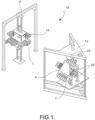
- an assembly 1 for preforming a reinforced fabric sheet 2 is provided.
- sheet means an intermediate process product in a flexible structural state, for example plastically deformable.
- said reinforced fabric sheet 2 is a pre-impregnated fabric sheet (prepreg).
- pre-impregnated fabric means a reinforced fabric impregnated with thermoplastic material.
- said reinforced fabric sheet 2 is a fabric sheet impregnated with a thermoplastic adhesive.
- said reinforced fabric sheet 2 is a dry fabric sheet.
- Said reinforced fabric sheet 2 is intended to undergo at least one deforming action for making a preformed shell.
- preformed shell means a preformed panel, for example in the shape of sheet or dome or shell, having thin thickness but blocked in the shape thereof, which may be a finished product or which may be an intermediate process product, for example an intermediate process product suitable for forming the core of a finished product.
- said preformed shell forms the core of a finished product, for example the core of the dome of a motor vehicle helmet, the core of a shell of a suitcase, the core of a piece of sports equipment such as e.g. a ski, the core of a bodywork panel, the core of a shell made of aesthetic carbon.
- said preformed shell is consolidated by means of coating with thermohardening material, preferably reticulated material, thus becoming a consolidated shell.
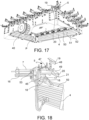
- Said assembly 1 comprises at least one frame 4.
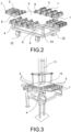
- said frame 4 comprises frame cross members 9, e.g. sectioned cross members, each frame cross member 9 having elongated shape which extends according to a longitudinal extension direction of cross members T-T, said frame cross members 9 forming a frame-like structure suitable for giving structural stability to said assembly 1.
- said frame 4 comprises cross members forming a peripheral structure suitable for surrounding, or at least partly surrounding, said reinforced fabric sheet 2. For example, if said reinforced fabric sheet has quadrangular shape, said frame 4 surrounds said sheet 2 and has quadrangular shape.
- said frame surrounds said reinforced fabric sheet 2 without however following the perimeter or edge portion of the reinforced fabric sheet 6 but in any case surrounding at least most of said sheet, thus leaving a through opening in direction transverse to the surface of said sheet 2.
- said frame 4 further comprises frame uprights.
- said frame 4 comprises ground contact units 22, for example wheels or rollers or shoes, suitable for allowing the movement of frame 4 for example, between adjacent stations in a preforming plant 10.
- said frame 4 comprises a frame gripping element 40 suitable for selectively connecting, or separately connecting on command, said frame 4 to a manipulator robot 41 suitable for manipulating said frame 4 to go through a loading station 42 to allow the assembly to grip said sheet 2 for example, resting on a support surface 43 so that it may be gripped and manipulated in successive stations, such as for example a preheating station 11 and a preform station 13, and also an unloading station 44.
- a frame gripping element 40 suitable for selectively connecting, or separately connecting on command, said frame 4 to a manipulator robot 41 suitable for manipulating said frame 4 to go through a loading station 42 to allow the assembly to grip said sheet 2 for example, resting on a support surface 43 so that it may be gripped and manipulated in successive stations, such as for example a preheating station 11 and a preform station 13, and also an unloading station 44.
- Said assembly 1 comprises a plurality of gripping devices 5 suitable for gripping the reinforced fabric sheet 2.
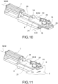
- each gripping device 5 comprises two opposed jaws 19, 20 which act in conjunction to grip a portion of the reinforced fabric sheet by pressing said reinforced fabric sheet on opposite sides.
- said opposed jaws 19, 20 are movable with respect to each other to achieve both a gripping action and a release action, opposite to said gripping action, of the portion of the reinforced fabric sheet 2 which is intended to be gripped.
- said gripping device 5 comprises a locking device 29 suitable for locking the related position of the opposed jaws 19, 20, for example when tightened.
- said locking device 29 comprises a safety knob 30 suitable for being gripped by an operator to manually actuate or disable the locking device 29, for example under breakdown or emergency conditions.
- Said plurality of gripping devices 5 is directly or indirectly associated with at least one frame 4, for example by means of a support 8.
- Each gripping device 5 of said plurality of gripping devices 5 is suitable for gripping an edge portion 6 of the reinforced fabric sheet 2.
- said plurality of gripping devices 5 substantially is in the shape of arms which are movable independently of one another, said arms being provided with said jaws 19, 20 suitable for gripping edge portions 6 of the reinforced fabric sheet 2 the same way as a plurality of hands.
- Said assembly 1 further comprises a moving system comprising a plurality of first moving devices 7.
- each first moving device 7 is independent in the movement thereof, of the other first moving devices 7 of said moving system.
- each gripping device 5 of said plurality of gripping devices is associated with a first moving device 7.
- each gripping device 5 is associated with a respective first moving device 7.
- each first moving device 7 is associated with a respective gripping device 6.
- each first moving device 7 is suitable for moving said respective gripping device 5 of said plurality of gripping devices independently of the others.
- each gripping device 5 is intended to be moved independently of the others by a respective first moving device 7.
- each gripping device 5 may move independently of the others to guide localized deformations of the reinforced fabric sheet 2, localized deformations which arise during the deforming action of the reinforced fabric sheet 2.
- the reinforced fabric sheet 2 gripped by said gripping devices 5 is closed in a preform mold 14 where it undergoes said deforming action, which here is induced by mechanical stress.
- the reinforced fabric sheet is allowed to be locally deformed during the closing of the preform mold 14 due to such an assembly 1 comprising gripping elements 5 which are independently movable of one another. Additionally, by approaching the preform mold 14, each gripping device 5 allows such a localized deformation of the reinforced fabric sheet to be accompanied without losing the grip on the respective edge portion 6. Simultaneously during the preforming, the provision of gripping elements 5 which are movable independently of one another allows the reinforced fabric sheet 2 to be kept locally stretched, i.e. a predetermined local pulling tension value to be kept. Preferably, said edge portion 6 of the reinforced fabric sheet 2 is intended to remain outside the preform mold 14 during the preforming.
- said first moving device 7 moves the respective gripping device 5 along a local moving direction M-M both close to and away from said mold 14.
- the reinforced fabric sheet 2 for example the pre-impregnated reinforced fabric sheet, gripped by said gripping devices 5, is heated, thus being subjected to said deforming action which here, is thermally induced.
- said first moving device 7 moves the respective gripping device 5 so as to accompany the deforming action induced thermally by heating.
- each gripping device 5 of said plurality of gripping devices is controlled according to the local force or the local pulling pressure undergone by the reinforced fabric sheet 2 to obtain a local stressing distribution of desired value over the reinforced fabric sheet 2.
- said assembly 1 comprises at least one sensor which locally detects the force of the pulling pressure undergone by the reinforced fabric sheet 2.
- said at least one sensor allows the independent movement of said gripping devices 5 to be controlled on the basis of information on the local stressing state of the reinforced fabric sheet.
- said assembly 1 comprises at least one control and operating unit 3 which receives information from said at least one sensor and transmits at least one control signal to the moving system.
- said at least one control and operating unit 3 comprises at least one programmable logical controller or PLC.
- said at least one control and operating unit 3 comprises at least one data processing control unit and at least one control unit operatively connected to said moving system.
- said first moving device 7 comprises at least one pneumatic actuator 15.
- said first moving device 7 comprises at least one pneumatically-operated actuator, preferably comprising at least one cylinder-piston assembly.
- said pneumatic actuator 15 is an air-operated actuator comprising a cylinder-piston assembly, in which the pressure of the air inside the cylinder of the cylinder-piston assembly locally balances the force of the pulling pressure undergone by the reinforced fabric sheet 2, preferably by the portion of the reinforced fabric sheet 2 gripped by said gripping device 5.
- said pneumatic actuator 15 is associated with said sensor, in which said sensor detects the pressure of the air inside the cylinder.
- said sensor is a manometer for regulating the pressure of the supply air of the actuator.
- said moving device 7 comprises at least one electric actuator.
- said moving device 7 comprises at least one electrically-operated or electromechanical actuator.
- said electric actuator is a permanent magnet linear motor, or is a rotary screw motor.
- said electromechanical actuator is associated with said sensor, in which said sensor is a load cell that detects the force or the pressure applied by the electromechanical actuator.
- said at least one sensor is operatively connected to said control and operating unit 3.
- said control and operating unit 3 controls the actuation of said moving system in a closed loop feedback manner.
- the feedback control is based on the information on the local stressing state detected by said sensor.
- said feedback control comprises a feedback branch operatively connected to a position sensor 37 that detects information on the position of said gripping device 5.
- said control and operating unit 3 controls the actuation of said moving system in open loop.
- said first moving device 7 is associated with a compressed air actuation circuit which comprises at least one valve 35, preferably a solenoid valve, operatively connected with said control and operating unit 3 and operatively connected with a compressor 36 suitable for providing pressurized air to said first moving device 7.
- said first moving device 7 is operatively connected to said control and operating unit 3 by means of two actuation branches, each of said two actuation branches comprising at least one valve 36, in which said two actuation branches form two counter branches.
- said at least one sensor is operatively connected to at least one display element 31 suitable for showing information on the local state of tension of the reinforced fabric sheet 2.
- said first moving device 7 comprises two actuators, for example two counter actuators 38, 39, comprising a first actuator 38 which exerts an initial preload on the reinforced fabric sheet 2 by keeping it stretched during the preheating step, and a second actuator 39 which operates the controlled release in the preforming.
- said first moving device 7 comprises at least one pair of counter actuators 38, 39.
- said at least one pair of counter actuators comprises a first actuator 38, or approaching actuator 38, suitable for moving said gripping device 5 close to said preform mold 14 during the preforming of said reinforced fabric sheet 2, and at least a second actuator 39, or distancing actuator 39, a counter actuator with respect to said approaching actuator, and suitable for moving said gripping device 5 away from said preform mold 14 during the preforming of said reinforced fabric sheet 2.
- the counter actuators 38, 39 forming said at least one pair of counter actuators are suitable for acting in conjunction to move the gripping device 5 in opposite directions along said local moving direction M-M.
- said frame 4 is a fixed frame, in which the mutual position and the orientation of the frame cross members 9 forming frame 4 is strictly predetermined.
- said frame 4 comprises two pairs of opposite frame cross members 9 forming a quadrangular frame; in other words, a quadrangular frame-like structure in which each frame cross member 9 supports at least one gripping device 5 and preferably a multiplicity of gripping devices 5 placed side-by-side one another and independently movable of one another at least along said local moving direction M-M.
- said frame cross members 9 define a frame, in other words a frame-like structure, suitable for surrounding, or at least partly surrounding, and preferably completely surrounding, said reinforced fabric sheet 2.
- the reinforced fabric sheet 2 may be stretched out before the preforming step due to the provision of said gripping devices 5.
- said frame cross members 9 with which said gripping devices 5 are associated form a frame which defines a frame plane which is substantially parallel or coinciding with said reinforced fabric sheet 2 when gripped by said gripping devices which keep it stretched before the preforming step, and preferably when said reinforced fabric sheet 2 is outside the preform mold 14.
- said frame plane substantially is horizontal or sub-horizontal.
- said frame 4 comprises at least one telescopically extending frame upright 33, and preferably at least one pair of telescopically extending frame uprights 33.
- frame 4 and in particular said frame plane may be freely oriented by bringing it to a predefined orientation with respect to the horizontal direction when for example, it is in the preform station 13 of a plant 10.
- the provision of such telescopically extending frame uprights 33 allows an improved versatility for making preformed shells having complex or irregular shape while ensuring satisfactory features of agreeable aesthetics in the distribution of the weft and the warp of the reinforced fabric sheet 2 during the preforming of the preformed shell.
- said assembly 1 comprises a plurality of supports 8 directly or indirectly associated with said frame 4, preferably with a frame cross member 9, each support 8 of said plurality of supports 8 also being directly or indirectly associated with at least one gripping device 5 so as to support said at least one gripping device 5.
- Each support preferably being directly associated with said frame 4 and directly with said gripping device.
- said assembly comprises a plurality of supports 8 in which each support 8 is associated, preferably directly associated, with a respective gripping device 5 and a respective first moving device 7 so as to support them.
- said at least one support 8 is hinged to frame 4.
- said at least one support 8 is associated with frame 4 by means of a spherical joint.
- said assembly 1 comprises a plurality of supports 8 in which each support 8 is associated with a respective gripping device 5 and at least a respective first moving device 7.
- said first moving device 7 is fastened to said support 8 and each gripping device 5 further comprises a carriage 21 associated with said support 8 and suitable for translating with respect to said support 8 when moved by said first moving device 7.
- said carriage 21 is fitted on said support 8.
- said first moving device 7 comprises at least one linear actuator, e.g. a linear pneumatic actuator 15, in which when actuated, a piston 28 of the cylinder-piston assembly exerts at least a thrust action on said carriage 21 of the gripping device 5.
- said linear actuator is suitable for also exerting a pulling action, opposite to said thrust action.
- said carriage 21 comprises at least one engagement portion 34 which forms an abutment for said first moving device 7 when said first moving device 7 is actuated.
- said at least one engagement portion 34 is integrally fastened with a thrust portion of the first moving device 7, for example with piston 38 of the cylinder-piston assembly of the pneumatic actuator 15.
- said moving system of said assembly 1 further comprises at least a second moving device, or support moving device, suitable for moving each support 8 independently of the other supports with respect to said frame 4.
- said second support moving device is suitable for moving each support 8 independently of the other supports with respect to said frame 4
- said first moving device 7 is suitable for moving each gripping device 5 independently of the other gripping devices with respect to said support 8.
- each first moving device (7) is movable independently of each second moving device.
- said second moving device and said first moving device 7 are the same moving device.
- said first moving device 7 and said second moving device are integrated in a single component, for example in the form of a cartridge.
- said second moving device moves said support 8 by a sliding movement in a sliding direction with respect to said frame 4.
- said sliding direction is orthogonal to said local moving direction M-M.
- said sliding direction is parallel or coinciding with said local moving direction M-M.
- said sliding direction is orthogonal and coplanar to the longitudinal extension direction of the frame cross member 9 with which said support 8 of the gripping device 5 is associated.
- said sliding direction defined by said second moving device substantially is parallel to the longitudinal extension direction T-T of the frame cross member 9 with which said support 8 of the gripping device 5 is associated.
- said frame cross member 9 comprises a guide element 32, for example a track 32, suitable for guiding the sliding movement of said support 8 caused by said second moving device, with respect to frame 4.
- said second moving device moves said support 8 by a rotary-translational movement about at least one rotation axis X-X or Y-Y with respect to said frame 4.
- said rotation axis X-X or Y-Y is movable with respect to said frame 4, thus defining a rotary-translational movement with respect to said frame 4.
- said rotation axis X-X or Y-Y is fixed and said rotary-translational movement is a rotation movement about said fixed axis with respect to said frame 4.
- said support 8 comprises at least one support joint 16.
- said support joint 16 is at least one of: a hinge, bushing, spherical joint suitable for forming a ball joint, and a universal joint.
- said support 8 is associated with said frame 4 by means of said support joint 16 which guides the rotation of support 8 with respect to frame 4.
- said rotation of support 8 with respect to frame 4 occurs about an axis which is transverse, and preferably orthogonal, to the edge portion 6 of the reinforced fabric sheet gripped by said gripping device 5, when in operating conditions.
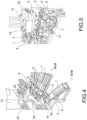
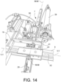
- said support 8 comprises a first plate 17 associated with said frame 4, and a second plate 18 associated with at least said gripping device 5.
- said support 8 further comprises said at least one support joint 16, for example a hinge of support 16, which connects said first plate 17 and said second plate 18 to each other, thus guiding the related rotary-translational movement about a movement axis X-X or Y-Y of said first plate 17 and of said second plate 18, thereby forming an articulated support 8 and defining and inclination angle ⁇ between said first plate 17 and said second plate 18 of support 8.
- said moving system preferably said second moving device, moves said second plate 18 in a controlled manner with respect to said first plate 17, thus affecting the inclination angle ⁇ .
- said at least one support joint 16 comprises at least one support hinge which defines a rotation axis X-X or Y-Y lying on a plane substantially parallel to said frame cross members 9 and preferably to the frame cross member 9 with which support 8 is associated.
- said inclination angle ⁇ is the angle formed between said plane parallel to the frame cross member 9 with which the first plate 17 of support 8 is associated, and the local moving direction M-M.
- said moving system comprises at least one elastic element which provides an elastic action which keeps said reinforced fabric sheet 2 preloaded by a predefined pretensioning value, by keeping it locally stretched.
- said elastic action provided by the at least one elastic element affects a respective gripping device 5 to move away from the preform mold 14 during the preforming, to keep said reinforced fabric sheet locally stretched.
- said plurality of gripping devices 5 is distributed, preferably distributed in a uniform manner, along the perimeter of the reinforced fabric sheet 2. According to one embodiment, said plurality of gripping devices 5 are arranged substantially equally spaced between one another to surround said reinforced fabric sheet 2 while each gripping an edge portion 6 of the reinforced fabric sheet.
- a plant 10 for preforming a reinforced fabric sheet 2 comprises at least one assembly 1 according to anyone of the embodiments described above.
- said plant 10 comprises at least one preheating station 11, comprising at least one preheating furnace 12.
- said plant 10 comprises at least one preform station 13, comprising at least one preform mold 14.
- said at least one preform mold 14 comprises at least two half-molds 23, 24 which cause the preforming shape; during the preforming, said at least two half-molds 23, 24 tighten and cause the subsequent deformation of the reinforced fabric sheet 2 to form said preformed shell.
- said two half-molds are mutually shaped.
- said preforming shape has a curved shape.
- at least one of said at least two half-molds 23, 24 comprises at least one convex face 25.
- said at least one preheating station 11 is integrated with said at least one preform station 13.
- at least one of said half-molds 23, 24 comprises at least one heating element, for example by heat radiation and/or by heat conduction.
- said plant 10 comprises an automatic feeding device suitable for transporting said reinforced fabric sheet 2 from said preheating station 11 to said preform station 13.
- said automatic feeding device is suitable for transporting said assembly 1 from said preheating station 11 to said preform station 13.
- said automatic feeding device comprises at least one robotic arm, for example of the SCARA type, and/or at least one conveyor belt.
- said frame 4 defines a frame plane P passing through said frame and which defines a plane in which the reinforced fabric sheet 2 is placed when, gripped by said plurality of gripping devices 5, it is held stretched, raised off all other supports or molds or half-molds.
- second geometrical coupling surfaces of second jaw 49 define a frame plane P.
- said frame 4 is suitable for surrounding said reinforced fabric sheet 2 to grip an edge portion of the reinforced fabric sheet 6 with said plurality of gripping devices 5 and to exert a controlled pulling and/or thrust action [different from an action of a spring or a weight which are constant over time] in a direction both of the frame plane P and outside the frame plane P, thus allowing an inclined arrangement of the reinforced fabric sheet 2 with respect to said frame 4 and in particular, to said frame plane P.
- each of said gripping devices 5 of said plurality of gripping devices 5 is connected to said frame 4.
- a first support plate 17 is comprised between said gripping device 5 and said frame 4. Said first support plate 17 is connected to said frame 4.
- a second support plate 18 is comprised between said gripping device 5 and said first support plate 17.
- said second support plate 18 is connected rotating to said first support plate 17 so as to oscillate and be positioned also tilted with respect to said frame 4 and/or with respect to said frame plane P.
- At least one support shoe 45 is comprised between said gripping device 5 and said second support plate 18.
- said gripping device 5 is connected to a support guide 46.
- said support guide 46 is slidingly housed in said support shoe 45.
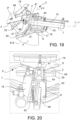
- said gripping device 5 comprises at least a first gripping device jaw 19 which acts in conjunction with a second gripping device jaw 20. At least one of said first and second gripping device jaw 19, 20 is movable so as to move away from and/or close to the other gripping device jaw 20, 19, thus opening and closing said gripping device 5.
- said assembly further comprises a jaw control device 47.
- Said at least one of said first and second gripping device jaw 19, 20 is connected to said jaw control device 47 for opening said at least one of said first and second gripping device jaw 19, 20 in a controlled manner.
- said first support plate 17 is connected to said frame 4 in a rotating manner.
- said first support plate 17 is connected to said frame 4 in a rotating manner about a rotation axis Y-Y arranged orthogonal to said frame plane P.
- said first support plate 17 is connected to said frame 4 in a rotating manner and is elastically and constantly stressed in a predefined angular position.
- said first support plate 17 is connected to said frame 4 in a rotating manner and the angular rotation thereof is controlled.
- said first support plate 17 is connected to said frame 4 in a rotating manner and the angular rotation thereof is operated in a controlled manner.
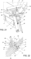
- said second support plate 18 is constantly stressed towards said first support plate 17.
- said second support plate 18 is elastically and constantly stressed towards said first support plate 17.
- the oscillation of said second support plate 18 is controlled with respect to said first support plate 17.
- the oscillation of said second support plate 18 is operated in a controlled manner with respect to said first support plate 17.
- said assembly 1 comprises a support plate spring 53, and in which said spring 53 is connected, with a first end thereof, to said first support plate 17, and to said second support plate 18 with the opposite end.
- said first gripping device jaw 19 comprises a first geometrical coupling surface of first jaw 48.
- said second gripping device jaw 20 comprises a second geometrical coupling surface of second jaw 49.
- Said first geometrical coupling surface of first jaw 48 geometrically couples with said second geometrical coupling surface of second jaw 49 when said gripping device 5 is in closed position, thus forming a winding clamping path therebetween for the gripping or grasping of said reinforced fabric sheet 2.
- said frame 3 comprises a frame upper edge 50, a frame inner edge 51 facing said reinforced fabric sheet and adjacent to said frame upper edge 50, and a frame lower edge 52, opposite to said frame upper edge (50) and adjacent to said frame inner edge 51.
- said plurality of gripping devices 5 is arranged on said frame upper edge 50.
- said plurality of gripping devices 5 each comprises a first gripping device jaw 19 suitable for acting in conjunction with a second gripping device jaw 20 to grip an edge portion 6 of a reinforced fabric sheet 2.
- Said second jaw 20 overhangingly protrudes from said frame upper edge 50 to form an overhanging support surface when said gripping device 5 is in an open positon ready to move close to said edge portion 6.
- said first jaw 19 is moved away from said second jaw 20, leaving a path orthogonal to a second geometrical coupling surface of second jaw free from obstacles to allow the reinforced fabric sheet 2 to approach resting on said second jaw 20.
- said assembly comprises a manipulator robot or device 54.
- Said robot 54 is connected to said frame 4 to manipulate said frame in a controlled manner.
- said robot 54 operates said plurality of gripping devices 5 to open and close.
- said robot 54 manipulates said frame 4 to pick at least one reinforced fabric sheet 2 and/or to bring said sheet 2 to a preheating station 11 and/or to bring said sheet 2 to a preform station 13 and/or to extract said preformed sheet 2 from a mold 23, 24.
- a method for preforming a reinforced fabric sheet for making a preformed shell is described below.
- a method for preforming a reinforced fabric sheet 2 for making a preformed shell comprises the following steps.
- the further steps of exerting at least one pulling and/or thrust pressure action on said reinforced fabric sheet 2, are comprised.
- the further steps are comprised of exerting at least a pulling and/or thrust pressure action on said reinforced fabric sheet 2 in a direction arranged outside a plane passing through a support frame 4 of said reinforced fabric sheet 2.
- the further steps are comprised of exerting at least a pulling and/or thrust pressure action on said reinforced fabric sheet 2 in a direction arranged outside a plane P passing through said reinforced fabric sheet 2, said plane P being defined when gripped by said plurality of gripping devices 5 when said sheet 2 is not resting on any other support, while said pulling or thrust action being exerted when said sheet 2 interacts with a mold 14 or half-mold 23, 24.
- the further steps are comprised of providing a frame 4 which at least partly surrounds said reinforced fabric sheet 2 and provides pluralities of gripping devices 5 arranged on said frame 4.
- the further steps of providing pluralities of gripping devices 5 in open position are comprised.
- the further steps are comprised of providing a plurality of open gripping devices 5 with the plurality of surfaces thereof or second geometrical coupling surfaces of second jaw 49 which define a frame plane P.
- the further steps of arranging a reinforced fabric sheet 2 on a support surface or loading station 57 are comprised.
- the further steps are comprised of moving said frame 4 close to the reinforced fabric sheet 2 with the second geometrical coupling surfaces of second jaw 49 facing said sheet 2.
- the further steps are comprised of tightening or closing said plurality of gripping devices 5 with a first geometrical coupling surface of first jaw 48 and gripping said sheet 2.
- the further steps of raising said sheet 2 gripped by the gripping devices 5, are comprised.
- the further steps of moving said sheet 2 are comprised.
- the further steps of bringing said sheet 2 into a preheating station 12, are comprised.
- the further steps are comprised of surrounding said preheating station 11 so that the gripping devices 5 may retain said sheet 2 without interfering with a preheating furnace 12, e.g. opposite heating plates 55, 56 which sandwich the opposite surfaces 26, 27 of the sheet 5.
- the further steps of bringing said sheet 2 onto a female half-mold 24, are comprised.
- the further steps are comprised of arranging frame 4 on and about said female half-mold 24 to surround, or at least partly surround, said female half-mold 24 so that gripping devices 5 may oscillate, translate or rotate and be arranged inclined with respect to said frame plane P, thus remaining outside the closing trajectory of the half-molds 23, 24 but facing the gap 58 which is gradually closed between the two half-molds 23, 24 so as to tension/pull or push said sheet 2 during the forming thereof.
- the further steps are comprised of moving or oscillating or rotating the pulling or thrust direction exerted by the gripping devices 5 with respect to said frame plane P and/or with respect to a direction which is perpendicular to said frame plane P.
- the further steps of opening said gripping devices 5 before the complete closing of the half-molds 23, 24, are comprised.
- the further steps of opening said gripping devices 5 at the complete closing of the half-molds 23, 24, are comprised.
- the further steps of opening said gripping devices 5 after the complete closing of the half-molds 23, 24, are comprised.
- a preformed shell may be obtained due to such a method.
- the above-indicated steps are to be provided in sequence in the order indicated.
- said method comprises the further step of exerting at least one pulling pressure action on said reinforced fabric sheet.
- said pulling pressure is an action distributed over a main portion of said reinforced fabric sheet 2.
- said step of exerting at least one pulling pressure action on said reinforced fabric sheet comprises the sub-step of exerting at least one preheating pulling pressure, which is performed in a preheating furnace 12.
- said step of exerting at least one pulling pressure action on said reinforced fabric sheet comprises the sub-step of exerting at least one preforming pulling pressure, which is performed in a preform mold 14.
- said step of gripping a plurality of edge portions 6 of the reinforced fabric sheet 2 with a plurality of gripping devices 5 is performed while keeping said plurality of edge portions 5 of the reinforced fabric sheet outside the preform mold 14.
- said assembly 1 keeps them outside the shape defined by the at least two mold half-shells 23, 24.
- said step of gripping a plurality of edge portions 6 of the reinforced fabric sheet 2 with a plurality of gripping devices 5 is performed while distributing, preferably uniformly distributing, said plurality of gripping devices 5 along the whole perimeter of the reinforced fabric sheet.
- said method comprises the further step of consolidating said preformed shell, for example by coating it with at least one layer of thermohardening material, preferably reticulated material.
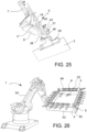
- an assembly 1 comprises a robot 54, e.g. an anthropomorphic robot, which connects the manipulating end, or effector end, thereof to a frame 4 on which a plurality of gripping devices 5 is arranged.
- a robot 54 e.g. an anthropomorphic robot, which connects the manipulating end, or effector end, thereof to a frame 4 on which a plurality of gripping devices 5 is arranged.
- At least one frame 4 may be automatically manipulated in a controlled manner and a plurality of gripping devices 5 may be moved in a controlled manner and for example, said frame 4 may be rotated to bring the gripping devices 5 with the jaws 19, 20 thereof in open position, and for example, the second jaws 20 ready to face a reinforced fabric sheet 2 to be gripped and manipulated.
- frame 4 may be completely rotated due to this assembly 1, therefore by arranging the gripping devices downwards on this surface arranged beforehand and facing a support surface 57 of a loading station for picking at least one reinforced fabric sheet 2 to be manipulated.
- the anthropomorphic robot 54 moves frame 4 and controls the gripping devices 5 by picking at least one reinforced fabric sheet 2.
- sheet 2 is gripped by the gripping devices 5, it is raised and turned upside-down so as to have the gripping devices 5 arranged on the upper side of frame 4.
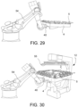
- Sheet 2 is then brought to a preheating station 11 where frame 4 is arranged about opposed heating plates 55, 56 which are closed - without interfering with the gripping devices 5 - against the opposite faces 26, 27 of the at least one reinforced fabric sheet 2 kept gripped by the gripping devices 5 arranged on frame 4.
- the plates 26, 27 of the preheating furnace 12 are opened and sheet 2 gripped by the gripping devices 5 is moved and brought towards a preform station 13 in which the half-molds 23, 24 are open.
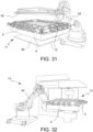
- robot 54 arranges frame 4 so as to surround the lower half-mold, or female half-mold 24, with the gripping devices 5 arranged close to the edge of the half-mold 24 and ready to guide the preheated reinforced fabric sheet 2 into gap 58 formed by the two closing half-molds 23, 24 by adjusting, with its gripping device 5 movements, the pulling of the edge portion 6 of reinforced fabric sheet 2 during the initial forming steps while the half-molds 23, 24 are closing, thus locally avoiding creases and distortions of fabric 2.
- multi-layer sheets or sandwiches may also be preformed as depicted in figure 34 , where for example, a shaped sheet, for example a shaped polyurethane sheet, is arranged between two reinforced fabric sheets.
- a preforming plant 10 comprises a loading station 44 of sheets 2 to be preformed, two opposite preheating stations 12, a robotic central assembly comprising an anthropomorphic robot 54 which supports a frame 4 on which a plurality of gripping devices 5 is arranged. Furthermore, the plant comprises a preform station 13, here a press with preforming half-molds 23, 24, a robot 61 for unloading the preformed sheet, a transport station 62 of the preformed sheets and a control station 60.
- the times required to preheat the reinforced fabric sheet 2 and continuously feed the preform station 13 may all be automatically optimized due to this solution.
- a plant 10 comprises, about a preform station 13, for example a preforming press in which there are arranged half-molds 23, 24, three anthropomorphic robots 54 suitable for manipulating support frames 4, each of a plurality of gripping devices 5 for simultaneously feeding mold 14 with two or more pre-shaped sheets 2 or cores for making sandwich components.
Landscapes
- Engineering & Computer Science (AREA)
- Mechanical Engineering (AREA)
- Chemical & Material Sciences (AREA)
- Composite Materials (AREA)
- Robotics (AREA)
- Moulding By Coating Moulds (AREA)
- Blow-Moulding Or Thermoforming Of Plastics Or The Like (AREA)
- Reinforced Plastic Materials (AREA)
Claims (14)
- Anordnung (1) zum Vorformen einer verstärkten Gewebebahn (2), wobei die verstärkte Gewebebahn (2) dazu bestimmt ist, mindestens eine Verformungswirkung zum Herstellen einer vorgeformten Hülle zu erhalten, umfassend:- mindestens einen Rahmen (4);- eine Vielzahl von Greifvorrichtungen (5), die dazu geeignet sind, die verstärkte Gewebebahn (2) zu greifen, wobei die Vielzahl von Greifvorrichtungen (5) direkt oder indirekt mit dem mindestens einen Rahmen (4) assoziiert sind;wobei:- jede Greifvorrichtung (5) der Vielzahl von Greifvorrichtungen (5) dazu geeignet ist, einen Randabschnitt (6) der verstärkten Gewebebahn (2) zu greifen;- die Anordnung (1) ferner ein bewegliches System, umfassend eine Vielzahl von ersten beweglichen Vorrichtungen (7), umfasst;wobei- die Bewegung jeder ersten beweglichen Vorrichtung (7) unabhängig von den anderen ersten beweglichen Vorrichtungen ist;- jede Greifvorrichtung (5) der Vielzahl von Greifvorrichtungen mit einer ersten beweglichen Vorrichtung (7) assoziiert ist;- wobei die erste bewegliche Vorrichtung (7) dazu geeignet ist, jede Greifvorrichtung (5) der Vielzahl von Greifvorrichtungen unabhängig von den anderen zu bewegen, so dass, wenn die verstärkte Gewebebahn (2) von der Vielzahl von Greifvorrichtungen (6) ergriffen ist, jede Greifvorrichtung sich bewegen kann, um lokalisierte Verformungen der verstärkten Gewebebahn (2) zu führen, die während der Verformungswirkung der verstärkten Gewebebahn (2) entstehen;dadurch gekennzeichnet, dass- die Anordnung (1) eine Vielzahl von Trägern (8) umfasst, die entweder direkt oder indirekt mit dem Rahmen (4) assoziiert sind, wobei jeder Träger (8) der Vielzahl von Trägern (8) ebenfalls entweder direkt oder indirekt mit mindestens einer Greifvorrichtung (5) assoziiert ist, um mindestens eine Greifvorrichtung (5) zu tragen; und wobei- jeder Träger (8) mit einer entsprechenden Greifvorrichtung (5) und mit einer entsprechenden ersten beweglichen Vorrichtung (7) assoziiert ist; und wobei- die erste bewegliche Vorrichtung (7) an dem Träger (8) befestigt ist und jede Greifvorrichtung (5) ferner einen Schlitten (21) umfasst, der mit dem Träger (8) assoziiert ist und dazu adaptiert ist, sich in Bezug auf den Träger (8) zu verschieben, wenn er von der ersten beweglichen Vorrichtung (7) bewegt wird; und wobei- mindestens einen Träger (8) mindestens ein Trägergelenk (16) umfasst; und wobei- der Träger (8) mit dem Rahmen (4) mittels des Trägergelenks (16) assoziiert ist, das die Drehung des Trägers (8) in Bezug auf den Rahmen (4) führt; und wobei- die Anordnung einen Manipulationsroboter oder eine Vorrichtung (54) umfasst, und wobei der Roboter (54) mit dem Rahmen (4) verbunden ist, um den Roboter in einer gesteuerten Weise zu manipulieren.
- Anordnung nach Anspruch 1, wobei- der Rahmen (4) eine Rahmenebene (P) definiert, die durch den Rahmen verläuft und die eine Ebene definiert, in der die verstärkte Gewebebahn (2) angeordnet ist, wenn sie, ergriffen von der Vielzahl von Greifvorrichtungen (5), gestreckt gehalten ist, angehoben von allen anderen Trägern oder Formen oder Halbformen, und wobei- zweite geometrische Kopplungsflächen einer zweiten Backe (49) eine Rahmenebene (P) definieren; oder wobei- der Rahmen (4) dazu geeignet ist, die verstärkte Gewebebahn (2) zu umgeben, um einen Randabschnitt der verstärkten Gewebebahn (6) mit der Vielzahl von Greifvorrichtungen (5) zu greifen und eine gesteuerte Zug- und/oder Druckwirkung in einer Richtung sowohl in der Rahmenebene (P) als auch außerhalb der Rahmenebene (P) auszuüben, wodurch eine schräge Anordnung der verstärkten Gewebebahn (2) in Bezug auf den Rahmen (4) und insbesondere auf die Rahmenebene (P) ermöglicht ist;oder wobeijede der Greifvorrichtungen (5) der Vielzahl von Greifvorrichtungen (5) mit dem Rahmen (4) verbunden ist; und wobeieine erste Trägerplatte (17) zwischen der Greifvorrichtung (5) und dem Rahmen (4) umfasst ist; und wobeidie erste Trägerplatte (17) mit dem Rahmen (4) verbunden ist;oder wobeieine zweite Trägerplatte (18) zwischen der Greifvorrichtung (5) und der ersten Trägerplatte (17) umfasst ist; und wobeidie zweite Trägerplatte (18) drehend mit der ersten Trägerplatte (17) verbunden ist, um zu oszillieren und auch geneigt in Bezug auf den Rahmen (4) und/oder in Bezug auf die Rahmenebene (P) positioniert zu sein; undwobeimindestens einen Trägerschuh (45) zwischen der Greifvorrichtung (5) und der zweiten Trägerplatte (18) umfasst ist; und wobeidie Greifvorrichtung (5) mit einer Trägerführung (46) assoziiert ist; und wobei die Trägerführung (46) gleitend in dem Trägerschuh (45) untergebracht ist; oder wobeidie Greifvorrichtung (5) mindestens eine erste Greifvorrichtungsbacke (19) umfasst, die mit einer zweiten Greifvorrichtungsbacke (20) zusammenwirkt;und wobeimindestens eine der ersten und zweiten Greifvorrichtungsbacke (19, 20) beweglich ist, um sich von der anderen Greifvorrichtungsbacke (20, 19) zu entfernen und/oder sich ihr zu nähern, wodurch die Greifvorrichtung (5) geöffnet und geschlossen wirdoder wobeidie Anordnung ferner eine Backensteuervorrichtung (47) umfasst; und wobei die mindestens eine der ersten und zweiten Greifvorrichtungsbacke (19, 20) mit der Backensteuervorrichtung (47) verbunden ist, um die mindestens eine der ersten und zweiten Greifvorrichtungsbacke (19, 20) in einer bedienten und/oder gesteuerten Weise zu öffnen;oder wobeidie erste Trägerplatte (17) in einer drehenden Weise mit dem Rahmen (4) verbunden ist; oder wobeidie erste Trägerplatte (17) mit dem Rahmen (4) in einer drehenden Weise um eine orthogonal zur Rahmenebene (P) angeordnete Drehachse (Y-Y) verbunden ist; oder wobeidie erste Trägerplatte (17) in einer drehenden Weise mit dem Rahmen (4) verbunden ist und in einer vordefinierten Winkelposition elastisch und konstant belastet wird; oder wobeidie erste Trägerplatte (17) in einer drehenden Weise mit dem Rahmen (4) verbunden ist und die Winkeldrehung davon gesteuert wird; oder wobei die erste Trägerplatte (17) in einer drehenden Weise mit dem Rahmen (4) verbunden ist und ihre Winkeldrehung in einer gesteuerten Weise bedient wird; oder wobeidie zweite Trägerplatte (18) konstant in Richtung der ersten Trägerplatte (17) belastet wird; oder wobeidie zweite Trägerplatte (18) elastisch und konstant in Richtung der ersten Trägerplatte (17) belastet wird; oder wobeidie Oszillation der zweiten Trägerplatte (18) in Bezug auf die erste Trägerplatte (17) gesteuert wird; oder wobeidie Oszillation der zweiten Trägerplatte (18) in Bezug auf die erste Trägerplatte (17) in einer gesteuerten Weise gesteuert wird; oder wobeidie Anordnung (1) eine Trägerplattenfeder (53) umfasst, und wobei die Feder (53) mit einem ersten Ende davon mit der ersten Trägerplatte (17) und mit dem gegenüberliegenden Ende mit der zweiten Trägerplatte (18) verbunden ist; oder wobeidie erste Greifvorrichtungsbacke (19) eine erste geometrische Kopplungsfläche einer ersten Backe (48) umfasst; und wobei die zweite Greifvorrichtungsbacke (20) eine zweite geometrische Kopplungsfläche einer zweiten Backe (49) umfasst; und wobei die erste geometrische Kopplungsfläche der ersten Backe (48) geometrisch mit der zweiten geometrischen Kopplungsfläche der zweiten Backe (49) koppelt, wenn sich die Greifvorrichtung (5) in geschlossener Position befindet, wodurch ein gewundener Klemm-Weg dazwischen zum Greifen oder Ergreifen der verstärkten Gewebebahn (2) gebildet wird;oder wobeider Rahmen (3) einen oberen Rahmenrand (50), einen inneren Rahmenrand (51), der der verstärkten Gewebebahn zugewandt ist und an den oberen Rahmenrand (50) angrenzt, und einen unteren Rahmenrand (52), der dem oberen Rahmenrand (50) gegenüberliegt und an den inneren Rahmenrand (51) angrenzt, umfasst; und wobei die Vielzahl von Greifvorrichtungen (5) an dem oberen Rahmenrand (50) angeordnet ist; oder wobeidie Vielzahl von Greifvorrichtungen (5) jeweils eine erste Greifvorrichtungsbacke (19) umfasst, die dazu geeignet ist, in Verbindung mit einer zweiten Greifvorrichtungsbacke (20) zu wirken, um einen Randabschnitt (6) einer verstärkten Gewebebahn (2) zu greifen, wobeidie zweite Backe (20) überhängend von dem oberen Rahmenrand (50) herausragt, um eine überhängende Trägerfläche zu bilden, wenn sich die Greifvorrichtung (5) in einer offenen Position befindet und bereit ist, sich nahe an den Randabschnitt (6) zu bewegen; oder wobeidie erste Backe (19) von der zweiten Backe (20) wegbewegt wird, so dass ein Weg orthogonal zu einer zweiten geometrischen Kopplungsfläche der zweiten Backe frei von Hindernissen bleibt, um der verstärken Gewebebahn (2) zu erlauben, einem Aufliegen auf der zweiten Backe (20) nähern zu kommen; oder wobeider Roboter (54) die Vielzahl von Greifvorrichtungen (5) zum Öffnen und Schließen steuert; oder wobeider Roboter (54) den Rahmen (4) manipuliert, um mindestens eine verstärkte Gewebebahn (2) aufzunehmen und/oder die Bahn (2) zu einer Vorwärmstation (11) zu bringen und/oder die Bahn (2) zu einer Vorformstation (13) zu bringen und/oder die vorgeformte Bahn (2) aus einer Form (23, 24) zu extrahieren; oder wobeidie unabhängige Bewegung von jeder Greifvorrichtung (6) der Vielzahl von Greifvorrichtungen in Abhängigkeit von der lokalen Kraft oder dem lokalen Zugdruck, dem die verstärkte Gewebebahn (2) ausgesetzt ist, gesteuert wird, um eine lokale Spannungsverteilung mit einem gewünschten Wert über die verstärkte Gewebebahn (2) zu erhalten.
- Anordnung (1) nach Anspruch 1 oder 2, wobei eine oder mehrere der folgenden Alternativen bereitgestellt sind:- die Anordnung mindestens einen Sensor umfasst, der die Kraft des Zugdrucks, dem die verstärkte Gewebebahn (2) ausgesetzt ist, lokal detektiert; oder wobei- die Anordnung (1) mindestens eine Steuer- und Bedieneinheit (3) und mindestens einen Sensor umfasst, der lokal die Kraft oder den Zugdruck erfasst, der/dem die Bahn von verstärktem Gewebe (2) ausgesetzt war, wobei die mindestens eine Steuer- und Bedieneinheit (3) Informationen von dem mindestens einen Sensor empfängt und mindestens ein Steuersignal an das bewegliche System sendet; oder wobei- die Anordnung (1) mindestens eine Steuer- und Bedieneinheit (3) umfasst und die Steuer- und Bedieneinheit (3) die Betätigung des beweglichen Systems in einer geschlossenen Rückführkreis-Weise steuert; oder wobei- die Anordnung (1) mindestens eine Steuer- und Betätigungseinheit (3) umfasst und die Steuer- und Bedieneinheit (3) die Betätigung des beweglichen Systems im offenen Rückführkreis steuert.
- Anordnung (1) nach einem der vorhergehenden Ansprüche, wobei die erste beweglichen Vorrichtung (7) mindestens einen pneumatischen Aktuator (15) oder mindestens einen elektrisch betriebenen Aktuator umfasst; oder wobei- die erste bewegliche Vorrichtung (7) mindestens ein Paar von Gegenaktuatoren (38, 39) umfasst, die dazu geeignet sind, zusammenzuwirken, um die Greifvorrichtung (5) in entgegengesetzten Richtungen entlang einer lokalen Bewegungsrichtung (M-M) zu bewegen.
- Anordnung (1) nach Anspruch 1, wobei- das Trägergelenk (16) mindestens eines der folgenden ist: ein Scharnier, eine Buchse, ein sphärisches Gelenk, das dazu geeignet ist, ein Kugelgelenk zu bilden, und ein Universalgelenk; oder wobei- der Träger (8) eine erste Platte (17), die mit dem Rahmen (4) assoziiert ist, und eine zweite Platte (18), die zumindest mit der Greifvorrichtung (5) assoziiert ist, umfasst, wobei das Trägergelenk (16) die erste Platte (17) und die zweite Platte (18) miteinander verbindet, folglich die entsprechende Dreh-Translationsbewegung zwischen der ersten Platte (17) und der Trägerplatte (18) um eine Bewegungsachse (X-X) und/oder (Y-Y) führt, wodurch ein gelenkartiger Träger (8) gebildet wird und ein Neigungswinkel (α) zwischen der ersten Platte (17) und der zweiten Platte (18) des Trägers (8) definiert wird.
- Anordnung (1) nach entweder Anspruch 1 oder 5, wobei das bewegliche System ferner mindestens eine zweite bewegliche Vorrichtung umfasst, die dazu geeignet ist, jeden Träger (8) unabhängig von den anderen Trägern in Bezug auf den Rahmen (4) zu bewegen; oder wobei- jede erste bewegliche Vorrichtung (7) unabhängig von jeder zweiten beweglichen Vorrichtung beweglich ist; oder wobei- die erste bewegliche Vorrichtung (7) und die zweite bewegliche Vorrichtung dazu adaptiert sind, jeden Träger (8) unabhängig von den anderen Trägern, die in einer einzigen Komponente integriert sind, in Bezug auf den Rahmen (4) zu bewegen.
- Anordnung (1) nach einem der vorhergehenden Ansprüche, wobei das bewegliche System mindestens ein elastisches Element umfasst, das eine elastische Wirkung erzeugt, die die verstärkte Gewebebahn (2) vorgespannt hält, indem sie sie lokal gedehnt hält.
- Anordnung (1) nach einem der vorhergehenden Ansprüche, wobei die Vielzahl von Greifvorrichtungen (5) entlang des Umfangs der verstärkten Gewebebahn (2) verteilt ist, vorzugsweise in einer gleichmäßigen Weise verteilt ist.
- Anlage (10) zum Vorformen einer verstärkten Gewebebahn (2), umfassend:- mindestens eine Anordnung (1) nach einem der vorhergehenden Ansprüche;- mindestens eine Vorwärmstation (11), umfassend mindestens einen Vorwärmofen (12);- mindestens eine Vorformstation (13), umfassend mindestens eine Vorformform (14).
- Verfahren zum Vorformen einer verstärkten Gewebebahn (2) zum Herstellen einer vorgeformten Hülle, das die folgenden Schritte umfasst:- Bereitstellen einer Anordnung (1) nach Anspruch 1 mit einem Manipulationsroboter oder -vorrichtung (54);- Bereitstellen mindestens einer verstärkten Gewebebahn (2);- Greifen einer Vielzahl von entsprechenden Randabschnitten (6) der verstärkten Gewebebahn (2) mit einer Vielzahl von Greifvorrichtungen (5);- Bewegen mindestens einer Greifvorrichtung (5) unabhängig von den anderen, um lokalisierte Verformungen der verstärkten Gewebebahn (2) zu steuern, die während der Verformungswirkung der verstärkten Gewebebahn (2) entstehen;- Bewegen jeder Greifvorrichtung (5) unabhängig von den anderen;- Manipulieren des Rahmens (4) mit dem Roboter oder der Vorrichtung (54), um mindestens eine verstärkte Gewebebahn (2) zu entnehmen und/oder die Bahn (2) zu einer Vorwärmstation (11) zu bringen und/oder die Bahn (2) zu einer Vorformstation (13) zu bringen und/oder die vorgeformte Bahn (2) aus einer Form (23, 24) zu extrahieren.
- Verfahren nach Anspruch 10, umfassend den weiteren Schritt eines Ausübens von mindestens einer Zug- und/oder Druckwirkung auf die verstärkte Gewebebahn (2);
und/oder wobei dort der folgende weitere Schritt umfasst ist:Ausüben von mindestens einer Zug- und/oder Druckwirkung auf die verstärkte Gewebebahn (2) in einer Richtung, die außerhalb einer Ebene liegt, die durch einen Trägerrahmen (4) der verstärkten Gewebebahn (2) verläuft; und/oder wobeiAusüben von mindestens einer Zug- und/oder Druckwirkung auf die verstärkte Gewebebahn (2) in einer Richtung, die außerhalb einer Ebene (P) liegt, die durch die verstärkte Gewebebahn (2) verläuft, wobei die Ebene (P) definiert wird, wenn sie von der Vielzahl von Greifvorrichtungen (5) ergriffen wird, wenn die Bahn (2) nicht auf einer anderen Unterlage ruht, während die Zug- oder Druckwirkung ausgeübt wird, wenn die Bahn (2) mit einer Form (14) oder einer Halbform (23, 24) interagiert. - Verfahren nach Anspruch 10 oder 11, umfassend den Schritt eines Bereitstellens eines Rahmens (4), der die verstärkte Gewebebahn (2) zumindest teilweise umgibt; undBereitstellen einer Vielzahl von Greifvorrichtungen (5), die an dem Rahmen (4) angeordnet sind;oder wobei dort die folgenden weiteren Schritte bereitgestellt sind:- Bereitstellen einer Vielzahl von offenen Greifvorrichtungen (5) mit der Vielzahl von Flächen davon oder zweiter geometrischer Kopplungsflächen von einer zweiten Backe (49), die eine Rahmenebene (P) definieren;oder wobei dort die folgenden weiteren Schritte bereitgestellt sind:Anordnen einer verstärkten Gewebebahn (2) an einer Trägerfläche oder Ladestation (57);Bewegen des Rahmens (4) in die Nähe der verstärkten Gewebebahn (2),wobei die zweiten geometrischen Kopplungsflächen der zweiten Backe (49) der Bahn (2) zugewandt sind;oder wobei dort die folgenden weiteren Schritte bereitgestellt sind:Bringen der Bahn (2) zu einer Vorwärmstation (12)und wobei dort die folgenden weiteren Schritte bereitgestellt sind:Umgeben der Vorwärmstation (11), so dass die Greifvorrichtungen (5) die Bahn (2) halten können, ohne mit einen Vorwärmofen (12) zu interferieren, z.B. gegenüberliegende Heizplatten (55, 56), die die gegenüberliegenden Flächen (26, 27) der Bahn (5) sandwichartig umgeben;oder wobei dort die folgenden weiteren Schritte bereitgestellt sind:Bringen der Bahn (2) auf eine weibliche Halbform (24);und wobei dort die folgenden weiteren Schritte bereitgestellt sind:Anordnen des Rahmens (4) an und um die weibliche Halbform (24), um die weibliche Halbform (24) zu umgeben oder zumindest teilweise zu umgeben, so dass Greifvorrichtungen (5) oszillieren, sich verschieben oder drehen können und in Bezug auf die Rahmenebene (P) geneigt angeordnet werden können, so dass sie außerhalb der schließenden Bahnkurve der Halbformen (23, 24) bleiben, aber dem Spalt (58) zugewandt sind, der graduell zwischen den beiden Halbformen (23, 24) geschlossen wird, um die Bahn (2) während ihrer Formung zu spannen/zu ziehen oder zu drücken;oder wobei dort die folgenden weiteren Schritte bereitgestellt sind:Bewegen oder Oszillieren oder Drehen der Zug- oder Druckrichtung, die von den Greifvorrichtungen (5) ausgeübt wird, in Bezug auf die Rahmenebene (P) und/oder in Bezug auf eine Richtung, die senkrecht zu der Rahmenebene (P) ist;und wobei dort die folgenden weiteren Schritte bereitgestellt sind:
Öffnen der Greifvorrichtungen (5) bei dem vollständigen Schließen der Halbformen (23, 24), oder wobei dort die folgenden weiteren Schritte bereitgestellt sind:
Öffnen der Greifvorrichtungen (5) beim vollständigen Schließen der Halbformen (23, 24), oder wobei dort die folgenden weiteren Schritte bereitgestellt sind:
Öffnen der Greifvorrichtungen (5) nach dem vollständigen Schließen der Halbformen (23, 24). - Verfahren nach einem der Ansprüche 10 bis 12, wobei:- der Schritt eines Bewegens mindestens einer Greifvorrichtung (5) unabhängig von den anderen durch Steuern des lokalen Spannungszustandes der verstärkten Gewebebahn (2) und/oder durch Detektieren des lokalen Spannungszustandes der verstärkten Gewebebahn (2) durchgeführt wird; und/oder wobei- der Schritt eines Bewegens mindestens einer Greifvorrichtung (5) unabhängig von den anderen automatisch durchgeführt wird.
- Verfahren nach einem der Ansprüche 10 bis 13, wobei:- der Schritt eines Greifens einer Vielzahl von Randabschnitten (6) der verstärkten Gewebebahn (2) mit einer Vielzahl von Greifvorrichtungen (5) durchgeführt wird, während die Vielzahl von Randabschnitten (5) der verstärkten Gewebebahn außerhalb der Vorformungsform (14) gehalten wird; und/oder wobei- der Schritt eines Greifens einer Vielzahl von Randabschnitten (6) der verstärkten Gewebebahn (2) mit einer Vielzahl von Greifvorrichtungen (5) durchgeführt wird, während die Vielzahl von Greifvorrichtungen (5) entlang des gesamten Umfangs der verstärkten Gewebebahn verteilt, vorzugsweise gleichmäßig verteilt, wird; und/oder wobei
das Verfahren den weiteren Schritt eines Konsolidierens der vorgeformten Hülle, zum Beispiel durch dessen Beschichten mit mindestens einer Schicht aus thermohärtendem Material, umfasst.
Applications Claiming Priority (2)
| Application Number | Priority Date | Filing Date | Title |
|---|---|---|---|
| EP17197799.4A EP3473397B1 (de) | 2017-10-23 | 2017-10-23 | Anordnung, system und verfahren zur herstellung einer vorgeformten schale |
| PCT/IB2018/058205 WO2019082055A1 (en) | 2017-10-23 | 2018-10-22 | ASSEMBLY, INSTALLATION AND METHOD FOR MANUFACTURING A PREFORMED ENVELOPE |
Publications (3)
| Publication Number | Publication Date |
|---|---|
| EP3700727A1 EP3700727A1 (de) | 2020-09-02 |
| EP3700727C0 EP3700727C0 (de) | 2024-04-10 |
| EP3700727B1 true EP3700727B1 (de) | 2024-04-10 |
Family
ID=60382008
Family Applications (2)
| Application Number | Title | Priority Date | Filing Date |
|---|---|---|---|
| EP17197799.4A Active EP3473397B1 (de) | 2017-10-23 | 2017-10-23 | Anordnung, system und verfahren zur herstellung einer vorgeformten schale |
| EP18804394.7A Active EP3700727B1 (de) | 2017-10-23 | 2018-10-22 | Anordnung, system und verfahren zur herstellung einer vorgeformten schale |
Family Applications Before (1)
| Application Number | Title | Priority Date | Filing Date |
|---|---|---|---|
| EP17197799.4A Active EP3473397B1 (de) | 2017-10-23 | 2017-10-23 | Anordnung, system und verfahren zur herstellung einer vorgeformten schale |
Country Status (4)
| Country | Link |
|---|---|
| US (1) | US11524425B2 (de) |
| EP (2) | EP3473397B1 (de) |
| CN (1) | CN111448042B (de) |
| WO (1) | WO2019082055A1 (de) |
Families Citing this family (20)
| Publication number | Priority date | Publication date | Assignee | Title |
|---|---|---|---|---|
| CN112334293A (zh) * | 2018-06-15 | 2021-02-05 | 加布里埃拉·贝纳西 | 用于用皮革或织物涂覆面板的自动机器 |
| WO2020033484A1 (en) * | 2018-08-07 | 2020-02-13 | University Of Southern California | Hybrid formation of multi-layer prepreg composite sheet layup |
| IT201900015509A1 (it) | 2019-09-03 | 2021-03-03 | Leonardo Spa | Dispositivo di stampaggio a compressione di parti in materiale composito a partire da lastre in composito a matrice termoplastica |
| US11273611B2 (en) * | 2019-10-07 | 2022-03-15 | GM Global Technology Operations LLC | Reinforced preform and method for molding |
| US11511501B2 (en) * | 2019-10-07 | 2022-11-29 | GM Global Technology Operations LLC | Mold and method for molding a reinforced preform |
| KR102242517B1 (ko) * | 2019-12-13 | 2021-04-20 | 코오롱데크컴퍼지트 주식회사 | 열가소성 복합재 성형 공정 소재 고정 장치 |
| CN112721237A (zh) * | 2020-12-31 | 2021-04-30 | 华南理工大学 | 预应力碳纤维增强热塑性复合材料成型装置及方法 |
| US11752711B2 (en) * | 2021-01-18 | 2023-09-12 | Spirit Aerosystems, Inc. | System and method for promoting inter-ply slippage |
| GB2607073B (en) * | 2021-05-27 | 2024-03-06 | Gkn Aerospace Services Ltd | Non-crimp fibre forming |
| US20220402221A1 (en) * | 2021-06-18 | 2022-12-22 | Rohr, Inc. | Pressing a multi-layered preform into a shaped body |
| US11993031B2 (en) | 2021-06-18 | 2024-05-28 | Goodrich Corporation | Carbonization shape forming of oxidized PAN fiber preform |
| US12649697B2 (en) | 2021-06-18 | 2026-06-09 | Goodrich Corporation | Shape forming OPF preform |
| US11607836B1 (en) * | 2022-02-08 | 2023-03-21 | Aerlyte, Inc. | Heated polymeric sheet material feeding process |
| US11738479B1 (en) * | 2022-04-28 | 2023-08-29 | GM Global Technology Operations LLC | Mold for forming composite preforms with high precision |
| US12508747B2 (en) | 2022-10-31 | 2025-12-30 | Rohr, Inc. | Systems and methods for bladder pressure forming a preform into a shaped body |
| US12325668B2 (en) | 2022-10-31 | 2025-06-10 | Goodrich Corporation | Expandable male die bladder for match die shape-forming systems and methods |
| US20240140880A1 (en) * | 2022-10-31 | 2024-05-02 | Rohr, Inc. | Expandable male die bladder for match die shape-forming systems and methods |
| ES3071230T3 (de) * | 2023-01-11 | 2026-06-22 | Fund Aitiip | |
| FR3160123B1 (fr) * | 2024-03-15 | 2026-08-07 | Daher Aerospace | Dispositif et procédé pour l’estampage d’un flan composite à matrice thermoplastique |
| CN121337110B (zh) * | 2025-12-17 | 2026-02-24 | 浙江健诚鞋业集团股份有限公司 | 一种皮鞋表面处理用装置及其处理方法 |
Family Cites Families (17)
| Publication number | Priority date | Publication date | Assignee | Title |
|---|---|---|---|---|
| ES418621A1 (es) * | 1973-09-10 | 1976-02-16 | Central Corsetera Sa | Perfeccionamientos en maquinas para el moldeo y conforma- cion de laminas flexibles. |
| JP3708182B2 (ja) * | 1995-09-08 | 2005-10-19 | 株式会社アミノ | 薄板の絞り成形装置およびこれを利用した薄板連続加工設備 |
| US5843492A (en) * | 1996-06-11 | 1998-12-01 | Lear Corporation | Apparatus for multiple sheet line molding |
| US20030146543A1 (en) * | 2002-01-17 | 2003-08-07 | National Research Council Of Canada | Molding method and support system for thermoformable sheet material |
| US20050023729A1 (en) * | 2003-07-31 | 2005-02-03 | Smith Leslie E. | Formation of wide paint film parts |
| JP4470190B2 (ja) * | 2007-10-23 | 2010-06-02 | 新東工業株式会社 | 材料クランプ方法および該方法に用いられる材料クランプ装置 |
| CN102802924B (zh) * | 2009-06-12 | 2015-07-22 | 伊利诺斯工具制品有限公司 | 用于制造承载织物表面的装置和方法 |
| DE102010040970A1 (de) | 2010-09-17 | 2012-03-22 | Airbus Operations Gmbh | Verfahren und Vorrichtung zur Bereitstellung eines trockenen textilen Vorformlings |
| FR2997341B1 (fr) * | 2012-10-25 | 2016-12-23 | Valeo Systemes Thermiques | Procede de moulage de materiau composite dans lequel un tissu de fibres est tendu dans un cadre de maintien avant injection d'une matrice |
| DE102012024060A1 (de) * | 2012-12-07 | 2014-06-12 | Daimler Ag | Verfahren und Vorrichtung zur Herstellung eines Vorformlings aus einem Faserhalbzeug |
| WO2014115130A2 (en) * | 2013-01-28 | 2014-07-31 | Udayan Kanade | Multi-axis universal material testing system |
| ITMO20130292A1 (it) | 2013-10-16 | 2015-04-17 | Cms Spa | Metodo per formare una lastra di materiale termoplastico rinforzato |
| DE102014006930A1 (de) * | 2014-05-10 | 2015-11-12 | Daimler Ag | Verfahren zum Herstellen eines Bauteils aus faserverstärktem Kunststoff, und Spannrahmen zum Einspannen einer Fasermatte |
| TWM522842U (zh) * | 2016-01-19 | 2016-06-01 | Chang Yi Ind Co Ltd | 具有夾持拉伸部之熱壓成型裝置 |
| CN205326260U (zh) * | 2016-01-25 | 2016-06-22 | 张孟蓁 | 热可塑板材的夹持装置 |
| DE102016102689B4 (de) * | 2016-02-16 | 2021-02-25 | Dieffenbacher GmbH Maschinen- und Anlagenbau | Verfahren und Vorrichtung zur Herstellung von dreidimensionalen Vorformlingen im Zuge der Herstellung von faserverstärkten Formteilen und Vorformling |
| TWM525839U (zh) * | 2016-04-14 | 2016-07-21 | Liang-An Wei | 定位夾持裝置之滑動機構 |
-
2017
- 2017-10-23 EP EP17197799.4A patent/EP3473397B1/de active Active
-
2018
- 2018-10-22 CN CN201880078656.1A patent/CN111448042B/zh active Active
- 2018-10-22 EP EP18804394.7A patent/EP3700727B1/de active Active
- 2018-10-22 WO PCT/IB2018/058205 patent/WO2019082055A1/en not_active Ceased
- 2018-10-22 US US16/758,546 patent/US11524425B2/en active Active
Also Published As
| Publication number | Publication date |
|---|---|
| WO2019082055A1 (en) | 2019-05-02 |
| EP3700727C0 (de) | 2024-04-10 |
| EP3700727A1 (de) | 2020-09-02 |
| US11524425B2 (en) | 2022-12-13 |
| CN111448042B (zh) | 2023-03-24 |
| EP3473397A1 (de) | 2019-04-24 |
| US20200346419A1 (en) | 2020-11-05 |
| CN111448042A (zh) | 2020-07-24 |
| EP3473397B1 (de) | 2021-03-10 |
Similar Documents
| Publication | Publication Date | Title |
|---|---|---|
| US11524425B2 (en) | Assembly, plant and method for making a preformed shell | |
| JP3803087B2 (ja) | シェル型繊維強化プラスチック部品の製造方法及び製造装置 | |
| US9561602B2 (en) | Forming highly contoured composite parts | |
| US5217656A (en) | Method for making structural reinforcement preforms including energetic basting of reinforcement members | |
| US20140008928A1 (en) | Gripping device for manipulating flexible elements | |
| JP6820860B2 (ja) | 繊維敷設機およびワークピースに繊維ウェブを敷設する方法 | |
| CN113498375B (zh) | 用于在半成品的表面上喷射塑料元件的设备 | |
| EP0620091B1 (de) | Verfahren und Vorrichtung zur Herstellung von strukturellen verstärkten Vorformlingen, mit energetischen temporären Verkleben oder Heften | |
| JP5872689B2 (ja) | ドレープ成形及びプレス成形工具、並びにプリフォーム及び繊維プラスチック複合部品の製造方法 | |
| JP6910302B2 (ja) | 繊維複合部材を製造するシステム | |
| DE102012003094B4 (de) | Vorrichtung zum Halten und/oder Verformen eines Objektes sowie Verfahren zum Verformen eines Objektes | |
| US11364670B2 (en) | Device and method for stretching and/or shaping and/or applying a lamination of a film element, and laminating station and apparatus for laminating a component | |
| EP2881242B1 (de) | Kontinuierliche Vorformvorrichtung für Verbundstringer | |
| JP7767002B2 (ja) | 熱可塑性マトリクスによる複合材料のプレートから出発する複合材料による部品の圧縮成形装置 | |
| EP0571897B1 (de) | Automatische Zuführvorrichtung einer Presse zum Formen von thermoplastischen Platten | |
| WO2014199124A2 (en) | Object-handling device | |
| US11554519B2 (en) | Method for producing a three-dimensional preform from reinforcing fibers | |
| JP7674994B2 (ja) | 高度輪郭付け複合構造体を形成するための成形装置及び方法 | |
| EP4008531B1 (de) | Herstellungsvorrichtung, verfahren und system | |
| JP2012196904A (ja) | 繊維強化プラスチックの成形方法とその成形装置 | |
| JPH04144733A (ja) | 熱可塑性樹脂高性能繊維強化複合材料シートの成形装置 | |
| Potter | Reinforcement manipulation and preforming | |
| ITMI981459A1 (it) | Dispositivo di movimentazione per le piastre laterali delle macchine cambratrici |
Legal Events
| Date | Code | Title | Description |
|---|---|---|---|
| STAA | Information on the status of an ep patent application or granted ep patent |
Free format text: STATUS: UNKNOWN |
|
| STAA | Information on the status of an ep patent application or granted ep patent |
Free format text: STATUS: THE INTERNATIONAL PUBLICATION HAS BEEN MADE |
|
| PUAI | Public reference made under article 153(3) epc to a published international application that has entered the european phase |
Free format text: ORIGINAL CODE: 0009012 |
|
| STAA | Information on the status of an ep patent application or granted ep patent |
Free format text: STATUS: REQUEST FOR EXAMINATION WAS MADE |
|
| 17P | Request for examination filed |
Effective date: 20200423 |
|
| AK | Designated contracting states |
Kind code of ref document: A1 Designated state(s): AL AT BE BG CH CY CZ DE DK EE ES FI FR GB GR HR HU IE IS IT LI LT LU LV MC MK MT NL NO PL PT RO RS SE SI SK SM TR |
|
| AX | Request for extension of the european patent |
Extension state: BA ME |
|
| DAV | Request for validation of the european patent (deleted) | ||
| DAX | Request for extension of the european patent (deleted) | ||
| GRAP | Despatch of communication of intention to grant a patent |
Free format text: ORIGINAL CODE: EPIDOSNIGR1 |
|
| STAA | Information on the status of an ep patent application or granted ep patent |
Free format text: STATUS: GRANT OF PATENT IS INTENDED |
|
| INTG | Intention to grant announced |
Effective date: 20230706 |
|
| GRAJ | Information related to disapproval of communication of intention to grant by the applicant or resumption of examination proceedings by the epo deleted |
Free format text: ORIGINAL CODE: EPIDOSDIGR1 |
|
| STAA | Information on the status of an ep patent application or granted ep patent |
Free format text: STATUS: REQUEST FOR EXAMINATION WAS MADE |
|
| GRAP | Despatch of communication of intention to grant a patent |
Free format text: ORIGINAL CODE: EPIDOSNIGR1 |
|
| STAA | Information on the status of an ep patent application or granted ep patent |
Free format text: STATUS: GRANT OF PATENT IS INTENDED |
|
| INTC | Intention to grant announced (deleted) | ||
| INTG | Intention to grant announced |
Effective date: 20231120 |
|
| GRAS | Grant fee paid |
Free format text: ORIGINAL CODE: EPIDOSNIGR3 |
|
| GRAA | (expected) grant |
Free format text: ORIGINAL CODE: 0009210 |
|
| STAA | Information on the status of an ep patent application or granted ep patent |
Free format text: STATUS: THE PATENT HAS BEEN GRANTED |
|
| AK | Designated contracting states |
Kind code of ref document: B1 Designated state(s): AL AT BE BG CH CY CZ DE DK EE ES FI FR GB GR HR HU IE IS IT LI LT LU LV MC MK MT NL NO PL PT RO RS SE SI SK SM TR |
|
| REG | Reference to a national code |
Ref country code: GB Ref legal event code: FG4D |
|
| REG | Reference to a national code |
Ref country code: CH Ref legal event code: EP |
|
| REG | Reference to a national code |
Ref country code: DE Ref legal event code: R096 Ref document number: 602018067921 Country of ref document: DE |
|
| REG | Reference to a national code |
Ref country code: IE Ref legal event code: FG4D |
|
| U01 | Request for unitary effect filed |
Effective date: 20240506 |
|
| U07 | Unitary effect registered |
Designated state(s): AT BE BG DE DK EE FI FR IT LT LU LV MT NL PT SE SI Effective date: 20240516 |
|
| PG25 | Lapsed in a contracting state [announced via postgrant information from national office to epo] |
Ref country code: IS Free format text: LAPSE BECAUSE OF FAILURE TO SUBMIT A TRANSLATION OF THE DESCRIPTION OR TO PAY THE FEE WITHIN THE PRESCRIBED TIME-LIMIT Effective date: 20240810 |
|
| PG25 | Lapsed in a contracting state [announced via postgrant information from national office to epo] |
Ref country code: HR Free format text: LAPSE BECAUSE OF FAILURE TO SUBMIT A TRANSLATION OF THE DESCRIPTION OR TO PAY THE FEE WITHIN THE PRESCRIBED TIME-LIMIT Effective date: 20240410 |
|
| PG25 | Lapsed in a contracting state [announced via postgrant information from national office to epo] |
Ref country code: GR Free format text: LAPSE BECAUSE OF FAILURE TO SUBMIT A TRANSLATION OF THE DESCRIPTION OR TO PAY THE FEE WITHIN THE PRESCRIBED TIME-LIMIT Effective date: 20240711 |
|
| PG25 | Lapsed in a contracting state [announced via postgrant information from national office to epo] |
Ref country code: ES Free format text: LAPSE BECAUSE OF FAILURE TO SUBMIT A TRANSLATION OF THE DESCRIPTION OR TO PAY THE FEE WITHIN THE PRESCRIBED TIME-LIMIT Effective date: 20240410 |
|
| PG25 | Lapsed in a contracting state [announced via postgrant information from national office to epo] |
Ref country code: PL Free format text: LAPSE BECAUSE OF FAILURE TO SUBMIT A TRANSLATION OF THE DESCRIPTION OR TO PAY THE FEE WITHIN THE PRESCRIBED TIME-LIMIT Effective date: 20240410 |
|
| PG25 | Lapsed in a contracting state [announced via postgrant information from national office to epo] |
Ref country code: PL Free format text: LAPSE BECAUSE OF FAILURE TO SUBMIT A TRANSLATION OF THE DESCRIPTION OR TO PAY THE FEE WITHIN THE PRESCRIBED TIME-LIMIT Effective date: 20240410 Ref country code: NO Free format text: LAPSE BECAUSE OF FAILURE TO SUBMIT A TRANSLATION OF THE DESCRIPTION OR TO PAY THE FEE WITHIN THE PRESCRIBED TIME-LIMIT Effective date: 20240710 Ref country code: IS Free format text: LAPSE BECAUSE OF FAILURE TO SUBMIT A TRANSLATION OF THE DESCRIPTION OR TO PAY THE FEE WITHIN THE PRESCRIBED TIME-LIMIT Effective date: 20240810 Ref country code: HR Free format text: LAPSE BECAUSE OF FAILURE TO SUBMIT A TRANSLATION OF THE DESCRIPTION OR TO PAY THE FEE WITHIN THE PRESCRIBED TIME-LIMIT Effective date: 20240410 Ref country code: GR Free format text: LAPSE BECAUSE OF FAILURE TO SUBMIT A TRANSLATION OF THE DESCRIPTION OR TO PAY THE FEE WITHIN THE PRESCRIBED TIME-LIMIT Effective date: 20240711 Ref country code: ES Free format text: LAPSE BECAUSE OF FAILURE TO SUBMIT A TRANSLATION OF THE DESCRIPTION OR TO PAY THE FEE WITHIN THE PRESCRIBED TIME-LIMIT Effective date: 20240410 Ref country code: RS Free format text: LAPSE BECAUSE OF FAILURE TO SUBMIT A TRANSLATION OF THE DESCRIPTION OR TO PAY THE FEE WITHIN THE PRESCRIBED TIME-LIMIT Effective date: 20240710 |
|
| REG | Reference to a national code |
Ref country code: DE Ref legal event code: R097 Ref document number: 602018067921 Country of ref document: DE |
|
| PG25 | Lapsed in a contracting state [announced via postgrant information from national office to epo] |
Ref country code: CZ Free format text: LAPSE BECAUSE OF FAILURE TO SUBMIT A TRANSLATION OF THE DESCRIPTION OR TO PAY THE FEE WITHIN THE PRESCRIBED TIME-LIMIT Effective date: 20240410 |
|
| PG25 | Lapsed in a contracting state [announced via postgrant information from national office to epo] |
Ref country code: SK Free format text: LAPSE BECAUSE OF FAILURE TO SUBMIT A TRANSLATION OF THE DESCRIPTION OR TO PAY THE FEE WITHIN THE PRESCRIBED TIME-LIMIT Effective date: 20240410 Ref country code: RO Free format text: LAPSE BECAUSE OF FAILURE TO SUBMIT A TRANSLATION OF THE DESCRIPTION OR TO PAY THE FEE WITHIN THE PRESCRIBED TIME-LIMIT Effective date: 20240410 |
|
| PG25 | Lapsed in a contracting state [announced via postgrant information from national office to epo] |
Ref country code: SM Free format text: LAPSE BECAUSE OF FAILURE TO SUBMIT A TRANSLATION OF THE DESCRIPTION OR TO PAY THE FEE WITHIN THE PRESCRIBED TIME-LIMIT Effective date: 20240410 |
|
| PG25 | Lapsed in a contracting state [announced via postgrant information from national office to epo] |
Ref country code: SM Free format text: LAPSE BECAUSE OF FAILURE TO SUBMIT A TRANSLATION OF THE DESCRIPTION OR TO PAY THE FEE WITHIN THE PRESCRIBED TIME-LIMIT Effective date: 20240410 Ref country code: SK Free format text: LAPSE BECAUSE OF FAILURE TO SUBMIT A TRANSLATION OF THE DESCRIPTION OR TO PAY THE FEE WITHIN THE PRESCRIBED TIME-LIMIT Effective date: 20240410 Ref country code: RO Free format text: LAPSE BECAUSE OF FAILURE TO SUBMIT A TRANSLATION OF THE DESCRIPTION OR TO PAY THE FEE WITHIN THE PRESCRIBED TIME-LIMIT Effective date: 20240410 Ref country code: CZ Free format text: LAPSE BECAUSE OF FAILURE TO SUBMIT A TRANSLATION OF THE DESCRIPTION OR TO PAY THE FEE WITHIN THE PRESCRIBED TIME-LIMIT Effective date: 20240410 |
|
| PLBE | No opposition filed within time limit |
Free format text: ORIGINAL CODE: 0009261 |
|
| STAA | Information on the status of an ep patent application or granted ep patent |
Free format text: STATUS: NO OPPOSITION FILED WITHIN TIME LIMIT |
|
| 26N | No opposition filed |
Effective date: 20250113 |
|
| U21 | Renewal fee for the european patent with unitary effect paid with additional fee |
Year of fee payment: 7 Effective date: 20250422 |
|
| REG | Reference to a national code |
Ref country code: CH Ref legal event code: PL |
|
| GBPC | Gb: european patent ceased through non-payment of renewal fee |
Effective date: 20241022 |
|
| PG25 | Lapsed in a contracting state [announced via postgrant information from national office to epo] |
Ref country code: MC Free format text: LAPSE BECAUSE OF FAILURE TO SUBMIT A TRANSLATION OF THE DESCRIPTION OR TO PAY THE FEE WITHIN THE PRESCRIBED TIME-LIMIT Effective date: 20240410 |
|
| PG25 | Lapsed in a contracting state [announced via postgrant information from national office to epo] |
Ref country code: GB Free format text: LAPSE BECAUSE OF NON-PAYMENT OF DUE FEES Effective date: 20241022 |
|
| PG25 | Lapsed in a contracting state [announced via postgrant information from national office to epo] |
Ref country code: CH Free format text: LAPSE BECAUSE OF NON-PAYMENT OF DUE FEES Effective date: 20241031 |
|
| PG25 | Lapsed in a contracting state [announced via postgrant information from national office to epo] |
Ref country code: IE Free format text: LAPSE BECAUSE OF NON-PAYMENT OF DUE FEES Effective date: 20241022 |
|
| U20 | Renewal fee for the european patent with unitary effect paid |
Year of fee payment: 8 Effective date: 20251020 |
|
| PG25 | Lapsed in a contracting state [announced via postgrant information from national office to epo] |
Ref country code: CY Free format text: LAPSE BECAUSE OF FAILURE TO SUBMIT A TRANSLATION OF THE DESCRIPTION OR TO PAY THE FEE WITHIN THE PRESCRIBED TIME-LIMIT; INVALID AB INITIO Effective date: 20181022 |
|
| PG25 | Lapsed in a contracting state [announced via postgrant information from national office to epo] |
Ref country code: HU Free format text: LAPSE BECAUSE OF FAILURE TO SUBMIT A TRANSLATION OF THE DESCRIPTION OR TO PAY THE FEE WITHIN THE PRESCRIBED TIME-LIMIT; INVALID AB INITIO Effective date: 20181022 |
|
| PG25 | Lapsed in a contracting state [announced via postgrant information from national office to epo] |
Ref country code: TR Free format text: LAPSE BECAUSE OF FAILURE TO SUBMIT A TRANSLATION OF THE DESCRIPTION OR TO PAY THE FEE WITHIN THE PRESCRIBED TIME-LIMIT Effective date: 20240410 |