EP3700255B1 - Verfahren, endgerätevorrichtung und netzwerkvorrichtung zur konfigurierung von messintervallen - Google Patents
Verfahren, endgerätevorrichtung und netzwerkvorrichtung zur konfigurierung von messintervallen Download PDFInfo
- Publication number
- EP3700255B1 EP3700255B1 EP17929490.5A EP17929490A EP3700255B1 EP 3700255 B1 EP3700255 B1 EP 3700255B1 EP 17929490 A EP17929490 A EP 17929490A EP 3700255 B1 EP3700255 B1 EP 3700255B1
- Authority
- EP
- European Patent Office
- Prior art keywords
- terminal device
- radio frequency
- measurement gap
- frequency channels
- configuration information
- Prior art date
- Legal status (The legal status is an assumption and is not a legal conclusion. Google has not performed a legal analysis and makes no representation as to the accuracy of the status listed.)
- Active
Links
Images
Classifications
-
- H—ELECTRICITY
- H04—ELECTRIC COMMUNICATION TECHNIQUE
- H04W—WIRELESS COMMUNICATION NETWORKS
- H04W24/00—Supervisory, monitoring or testing arrangements
- H04W24/10—Scheduling measurement reports ; Arrangements for measurement reports
-
- H—ELECTRICITY
- H04—ELECTRIC COMMUNICATION TECHNIQUE
- H04B—TRANSMISSION
- H04B17/00—Monitoring; Testing
- H04B17/30—Monitoring; Testing of propagation channels
- H04B17/309—Measuring or estimating channel quality parameters
-
- H—ELECTRICITY
- H04—ELECTRIC COMMUNICATION TECHNIQUE
- H04B—TRANSMISSION
- H04B17/00—Monitoring; Testing
- H04B17/30—Monitoring; Testing of propagation channels
- H04B17/382—Monitoring; Testing of propagation channels for resource allocation, admission control or handover
-
- H—ELECTRICITY
- H04—ELECTRIC COMMUNICATION TECHNIQUE
- H04W—WIRELESS COMMUNICATION NETWORKS
- H04W24/00—Supervisory, monitoring or testing arrangements
- H04W24/08—Testing, supervising or monitoring using real traffic
-
- H—ELECTRICITY
- H04—ELECTRIC COMMUNICATION TECHNIQUE
- H04W—WIRELESS COMMUNICATION NETWORKS
- H04W36/00—Hand-off or reselection arrangements
- H04W36/0005—Control or signalling for completing the hand-off
- H04W36/0055—Transmission or use of information for re-establishing the radio link
- H04W36/0069—Transmission or use of information for re-establishing the radio link in case of dual connectivity, e.g. decoupled uplink/downlink
- H04W36/00698—Transmission or use of information for re-establishing the radio link in case of dual connectivity, e.g. decoupled uplink/downlink using different RATs
-
- H—ELECTRICITY
- H04—ELECTRIC COMMUNICATION TECHNIQUE
- H04W—WIRELESS COMMUNICATION NETWORKS
- H04W36/00—Hand-off or reselection arrangements
- H04W36/0005—Control or signalling for completing the hand-off
- H04W36/0083—Determination of parameters used for hand-off, e.g. generation or modification of neighbour cell lists
- H04W36/0085—Hand-off measurements
- H04W36/0088—Scheduling hand-off measurements
-
- H—ELECTRICITY
- H04—ELECTRIC COMMUNICATION TECHNIQUE
- H04W—WIRELESS COMMUNICATION NETWORKS
- H04W72/00—Local resource management
- H04W72/04—Wireless resource allocation
- H04W72/044—Wireless resource allocation based on the type of the allocated resource
- H04W72/0453—Resources in frequency domain, e.g. a carrier in FDMA
-
- H—ELECTRICITY
- H04—ELECTRIC COMMUNICATION TECHNIQUE
- H04W—WIRELESS COMMUNICATION NETWORKS
- H04W72/00—Local resource management
- H04W72/20—Control channels or signalling for resource management
- H04W72/21—Control channels or signalling for resource management in the uplink direction of a wireless link, i.e. towards the network
-
- H—ELECTRICITY
- H04—ELECTRIC COMMUNICATION TECHNIQUE
- H04W—WIRELESS COMMUNICATION NETWORKS
- H04W72/00—Local resource management
- H04W72/20—Control channels or signalling for resource management
- H04W72/23—Control channels or signalling for resource management in the downlink direction of a wireless link, i.e. towards a terminal
-
- H—ELECTRICITY
- H04—ELECTRIC COMMUNICATION TECHNIQUE
- H04W—WIRELESS COMMUNICATION NETWORKS
- H04W72/00—Local resource management
- H04W72/50—Allocation or scheduling criteria for wireless resources
- H04W72/51—Allocation or scheduling criteria for wireless resources based on terminal or device properties
-
- H—ELECTRICITY
- H04—ELECTRIC COMMUNICATION TECHNIQUE
- H04W—WIRELESS COMMUNICATION NETWORKS
- H04W8/00—Network data management
- H04W8/22—Processing or transfer of terminal data, e.g. status or physical capabilities
- H04W8/24—Transfer of terminal data
-
- H—ELECTRICITY
- H04—ELECTRIC COMMUNICATION TECHNIQUE
- H04W—WIRELESS COMMUNICATION NETWORKS
- H04W8/00—Network data management
- H04W8/22—Processing or transfer of terminal data, e.g. status or physical capabilities
- H04W8/24—Transfer of terminal data
- H04W8/245—Transfer of terminal data from a network towards a terminal
-
- H—ELECTRICITY
- H04—ELECTRIC COMMUNICATION TECHNIQUE
- H04W—WIRELESS COMMUNICATION NETWORKS
- H04W84/00—Network topologies
- H04W84/02—Hierarchically pre-organised networks, e.g. paging networks, cellular networks, WLAN [Wireless Local Area Network] or WLL [Wireless Local Loop]
-
- H—ELECTRICITY
- H04—ELECTRIC COMMUNICATION TECHNIQUE
- H04W—WIRELESS COMMUNICATION NETWORKS
- H04W88/00—Devices specially adapted for wireless communication networks, e.g. terminals, base stations or access point devices
- H04W88/02—Terminal devices
- H04W88/06—Terminal devices adapted for operation in multiple networks or having at least two operational modes, e.g. multi-mode terminals
-
- H—ELECTRICITY
- H04—ELECTRIC COMMUNICATION TECHNIQUE
- H04W—WIRELESS COMMUNICATION NETWORKS
- H04W88/00—Devices specially adapted for wireless communication networks, e.g. terminals, base stations or access point devices
- H04W88/08—Access point devices
- H04W88/10—Access point devices adapted for operation in multiple networks, e.g. multi-mode access points
-
- H—ELECTRICITY
- H04—ELECTRIC COMMUNICATION TECHNIQUE
- H04W—WIRELESS COMMUNICATION NETWORKS
- H04W92/00—Interfaces specially adapted for wireless communication networks
- H04W92/02—Inter-networking arrangements
-
- H—ELECTRICITY
- H04—ELECTRIC COMMUNICATION TECHNIQUE
- H04W—WIRELESS COMMUNICATION NETWORKS
- H04W92/00—Interfaces specially adapted for wireless communication networks
- H04W92/04—Interfaces between hierarchically different network devices
- H04W92/10—Interfaces between hierarchically different network devices between terminal device and access point, i.e. wireless air interface
-
- Y—GENERAL TAGGING OF NEW TECHNOLOGICAL DEVELOPMENTS; GENERAL TAGGING OF CROSS-SECTIONAL TECHNOLOGIES SPANNING OVER SEVERAL SECTIONS OF THE IPC; TECHNICAL SUBJECTS COVERED BY FORMER USPC CROSS-REFERENCE ART COLLECTIONS [XRACs] AND DIGESTS
- Y02—TECHNOLOGIES OR APPLICATIONS FOR MITIGATION OR ADAPTATION AGAINST CLIMATE CHANGE
- Y02D—CLIMATE CHANGE MITIGATION TECHNOLOGIES IN INFORMATION AND COMMUNICATION TECHNOLOGIES [ICT], I.E. INFORMATION AND COMMUNICATION TECHNOLOGIES AIMING AT THE REDUCTION OF THEIR OWN ENERGY USE
- Y02D30/00—Reducing energy consumption in communication networks
- Y02D30/70—Reducing energy consumption in communication networks in wireless communication networks
Definitions
- Embodiments of the present invention relate to the communications field, and more specifically, to a measurement gap configuration method, a terminal device, and a network device.
- 5G fifth-generation
- eMBB enhanced mobile broadband
- URLLC ultra-reliable and low-latency communication
- mMTC massive machine type communication
- LTE long term evolution
- NR island coverage mode a wide-area long term evolution (LTE) coverage mode and an NR island coverage mode.
- LTE long term evolution
- GHz gigahertz
- frequency spectrums below 6 GHz that may be used for 5G are rare. Therefore, in NR, application of frequency spectrums above 6 GHz needs to be researched, but high frequency bands have limited coverage and quick signal fading.
- LTE-NR dual-connectivity DC is supported through a bandwidth combination in transmitting data, thereby increasing a system throughput.
- CN 101784075 A discloses a method for allocating a measurement gap and the devices that can be used for carrying out such method.
- this document discusses the possibility of generating configuration information from a network device according to a measurement gap and sending said information to a terminal device.
- WO 2016/080899 A1 discloses a method and the corresponding apparatus for determining the connectivity mode of a User Equipment.
- this document discloses a network device that can obtain capability information concerning the User Equipment.
- EP 2624628 A1 discloses a measurement gap configuration method and the terminal/network devices carrying out such method.
- a measurement gap configuration method, a terminal device and a network device are provided, to enable a terminal device to flexibly process a measurement and data receiving/transmission process, to reduce impact of measurement on data receiving/transmission, thereby improving user experience.
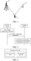
- FIG. 1 is a schematic diagram of an application scenario according to an embodiment of the present invention.
- a terminal device 110 is connected to a first network device 130 served by a first communications system and a second network device 120 served by a second communications system.
- the first network device 130 is a network device in long term evolution (LTE)
- the second network device 120 is a network device in new radio (NR).
- LTE long term evolution
- NR new radio
- the first network device 130 and the second network device 120 may include a plurality of cells.
- the terminal device 110 Before the terminal device 110 performs cell handover, the terminal device 110 normally measures power (signal quality) of a target cell and reports the power to the first network device 130, and the first network device 130 determines whether to allow the terminal device 110 to be handed over to the target cell.
- power signal quality
- the terminal device 110 can measure the signal quality of the target cell relatively easily; but if the target cell and the current cell have different frequencies (inter-frequency measurement), the terminal device 110 measures the signal quality of the target cell quite difficultly.
- a simplest inter-frequency measurement solution is to implement two radio frequency (RF) transceivers on UE.
- RF radio frequency
- the dual RF transceiver solution has actual difficulties, where one problem is costs, and additional costs are required to implement an additional transceiver; and another problem is possible interference that exists between a current frequency and a target frequency particularly when the two frequencies are close, and particularly in a dual-connectivity scenario.
- a method for configuring, by a network device, a measurement gap for a terminal device is proposed.
- a measurement gap of each radio frequency channel is defined, and configured for the terminal device, to enable the terminal device to flexibly process a measurement and data receiving/transmission process, to reduce impact of measurement on data receiving/transmission, thereby improving user experience.
- FIG. 1 shows an example of a scenario according to an embodiment of the present invention, but this embodiment of the present invention is not limited to what is shown in FIG. 1 .
- a communications system to which this embodiment of the present invention adapts may include at least a plurality of network devices served by the first communications system and/or a plurality of network devices served by the second communications system.
- the first communications system and the second communications system in this embodiment of the present invention are different, but specific types of the first communications system and the second communications system are not limited.
- the first communications system and the second communications system may be various communications systems, for example, a global system for mobile communications (GSM) system, a code division multiple access (CDMA) system, a wideband code division multiple access (WCDMA) system, a general packet radio service (GPRS) system, a long term evolution (LTE) system, an LTE time division duplex (TDD) system, and a universal mobile telecommunications system (UMTS) system.
- GSM global system for mobile communications
- CDMA code division multiple access
- WCDMA wideband code division multiple access
- GPRS general packet radio service
- LTE long term evolution
- TDD LTE time division duplex
- UMTS universal mobile telecommunications system
- the embodiments are described with reference to the network devices (the first network device to a fourth network device) and the terminal device.
- the network device may be any entity configured to send or receive a signal on a network side.
- the network device may be machine type communication (MTC) user equipment, a base transceiver station (BTS) in GSM or CDMA, a NodeB in WCDMA, an evolved NodeB (eNB or eNodeB) in LTE, or a base station device in a 5G network.
- MTC machine type communication
- BTS base transceiver station
- eNB evolved NodeB
- eNodeB evolved NodeB
- the terminal device 110 may be any terminal device. Specifically, the terminal device may communicate with one or more core networks through a radio access network (RAN), and may also be referred to as an access terminal, user equipment (UE), a subscriber unit, a subscriber station, a mobile station, a mobile console, a remote station, a remote terminal, a mobile device, a user terminal, a terminal, a wireless communications device, a user agent, or a user apparatus.
- RAN radio access network
- the terminal device may be a cellular phone, a cordless phone, a Session Initiation Protocol (SIP) phone, a wireless local loop (WLL) station, a personal digital assistant (PDA), a handheld device having a wireless communication function, a computing device, another processing device connected to a wireless modem, an in-vehicle device, a wearable device, or a terminal device in a 5G network.
- SIP Session Initiation Protocol
- WLL wireless local loop
- PDA personal digital assistant
- FIG. 2 is a schematic flowchart of a measurement gap configuration method according to an embodiment of the present invention.
- the method includes the following steps.
- a network device generates configuration information.
- the network device sends the configuration information to a terminal device.
- the terminal device performs signal quality measurement according to the configuration information.
- the terminal device receives the configuration information sent by the network device, wherein the configuration information includes at least one measurement gap corresponding to a plurality of radio frequency channels that the terminal device has; and then performs signal quality measurement according to the at least one measurement gap.
- the measurement gap configured for the terminal device may be used to perform inter-frequency measurement or intra-frequency measurement.
- the measurement gap configured for the terminal device (a current cell) is not used to send data and is not used to receive data either. Therefore, the terminal device may be handed over to a target cell and perform signal quality measurement, and then be handed over back to the current cell (continues a normal receiving/transmission operation).
- measurement gaps need to be kept synchronous between the terminal device and the network device (for example, a start location of the measurement gap, a length of the measurement gap, and quantity of the measurement gaps).
- a measurement gap based on radio frequency channels is defined, that is, a measurement gap is configured for radio frequency channels. It should be understood that, this measurement gap affects only data receiving/transmission of a data receive (Rx) channel/data transmit (Tx) channel of the current radio frequency channels; but does not affect data receiving/transmission of other radio frequency channels.
- a plurality of radio frequency channels of this embodiment of the present invention may be divided based on a frequency range, or may be divided based on a type of a communications system. This is not specifically limited in this embodiment of the present invention.
- the terminal device may support a plurality of radio frequency channels (particularly in a dual-connectivity scenario), and bands on which the radio frequency channels can perform measurement or bands supported by the radio frequency channels are different, which depends on capabilities of the radio frequency channels (supported by a power amplifier PA and an antenna).
- the terminal device for example, a mobile phone
- the terminal device after accessing a network, the terminal device needs to report information about a band that can be supported by the terminal device, and information about a band combination supported by carrier aggregation (CA), information about a band combination supported in a dual-connectivity (DC) scenario, and a measurement related capability.
- CA carrier aggregation
- DC dual-connectivity
- the terminal device may send radio frequency capability information of the terminal device to the network device, so that the network device generates the configuration information according to the radio frequency capability information.
- the radio frequency capability information includes at least one of the following information: quantity of radio frequency channels supported by the terminal device, information about a frequency spectrum supported by each radio frequency channel, radio frequency channel capability information, and indication information used to indicate whether the terminal device supports performing signal quality measurement according to the measurement gap corresponding to the plurality of radio frequency channels.
- the terminal device needs to report the radio frequency capability information of the terminal device, so that the network device generates the configuration information according to the radio frequency capability information of the terminal device.
- the radio frequency channel capability information includes at least one of the following information: quantity of the plurality of radio frequency channels, a multiple-input multiple-output MIMO capability, quantity of data receiving channels, quantity of data transmitting channels, and a carrier aggregation supporting capability.
- the plurality of radio frequency channels in this embodiment of the present invention corresponds to at least one measurement gap.
- each of the plurality of radio frequency channels may correspond to one measurement gap.
- a first measurement gap corresponding to a first radio frequency channel of the plurality of radio frequency channels is only used to perform measurement on the first radio frequency channel.
- the terminal device has two radio frequency channels: RF-CH1 and RF-CH2.
- the network device may respectively configure individual gap1 and gap2 for the two radio frequency channels.
- the gap1 is used for the radio frequency channel RF-CH1
- the gap2 is used for the radio frequency channel RF-CH2.
- the gap1 is used.
- the terminal device performs measurement on the gap1, downlink receiving or the like of the terminal device on the radio frequency channel RF-CH2 is not affected.
- the plurality of radio frequency channels corresponds to a same measurement gap.
- the network device configures gap3 for the terminal device, and the gap3 is used for cross-radio frequency channel RF-CH1/radio frequency channel RF-CH2 measurement.
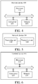
- FIG. 3 is a schematic block diagram of a terminal device according to an embodiment of the present invention.
- the terminal device 300 includes:
- the transceiver unit 310 is further configured to: send, before receiving the configuration information sent by the network device, radio frequency capability information of the terminal device to the network device, so that the network device generates the configuration information according to the radio frequency capability information.
- the radio frequency capability information includes at least one of the following information: quantity of radio frequency channels supported by the terminal device, information about a frequency spectrum supported by each radio frequency channel, radio frequency channel capability information, and indication information used to indicate whether the terminal device supports performing signal quality measurement according to the measurement gap corresponding to the plurality of radio frequency channels.
- the radio frequency channel capability information includes at least one of the following information: quantity of the plurality of radio frequency channels, a multiple-input multiple-output MIMO capability, quantity of data receiving channels, quantity of data transmitting channels, and a carrier aggregation supporting capability.
- each of the plurality of radio frequency channels corresponds to one measurement gap.
- a first measurement gap corresponding to a first radio frequency channel of the plurality of radio frequency channels is only used to perform measurement on the first radio frequency channel.
- the plurality of radio frequency channels corresponds to a same measurement gap.
- a terminal device 400 may include a processor 410, a transceiver 420, and a memory 430.
- the memory 430 may be configured to store indication information, and may be further configured to store code, an instruction, or the like executed by the processor 410.
- Components in the terminal device 400 are connected to each other through a bus system, where in addition to a data bus, the bus system further includes a power bus, a control bus, and a status signal bus.
- the terminal device 400 shown in FIG. 4 can implement each process, implemented by the terminal device, in the method embodiment in FIG. 2 . To avoid repetition, details are not described herein again.
- FIG. 5 is a schematic block diagram of a network device according to an embodiment of the present invention.
- a processing unit 510 is configured to generate configuration information, where the configuration information includes at least one measurement gap corresponding to a plurality of radio frequency channels that a terminal device has; and a transceiver unit 520 is configured to send the configuration information to the terminal device.
- the transceiver unit 510 is further configured to: receive, before generating the configuration information, radio frequency capability information of the terminal device sent by the terminal device, where the processing unit 510 is specifically configured to generate the configuration information according to the radio frequency capability information.
- the radio frequency capability information includes at least one of the following information: quantity of radio frequency channels supported by the terminal device, information about a frequency spectrum supported by each radio frequency channel, radio frequency channel capability information, and indication information used to indicate whether the terminal device supports performing signal quality measurement according to the measurement gap corresponding to the plurality of radio frequency channels.
- the radio frequency channel capability information includes at least one of the following information: quantity of the plurality of radio frequency channels, a multiple-input multiple-output MIMO capability, quantity of data receiving channels, quantity of data transmitting channels, and a carrier aggregation supporting capability.
- each of the plurality of radio frequency channels corresponds to one measurement gap.
- a first measurement gap corresponding to a first radio frequency channel of the plurality of radio frequency channels is only used to perform measurement on the first radio frequency channel.
- the plurality of radio frequency channels corresponds to a same measurement gap.
- a network device 600 may include a processor 610, a transceiver 620, and a memory 630.
- the memory 630 may be configured to store indication information, and may be further configured to store code, an instruction, or the like executed by the processor 610.
- Components in the network device 600 are connected to each other through a bus system, where in addition to a data bus, the bus system further includes a power bus, a control bus, and a status signal bus.
- the network device 600 shown in FIG. 6 can implement each process, implemented by the network device, in the method embodiment in FIG. 2 . To avoid repetition, details are not described herein again.
- the steps of the method embodiment of the embodiments of the present invention may be implemented by using a hardware integrated logic circuit in the processor or implemented by using an instruction in a software form. More specifically, steps of the methods disclosed with reference to the embodiments of the present invention may be directly executed and completed by means of a hardware decoding processor, or may be executed and completed by using a combination of hardware and software modules in the decoding processor.
- the software module may be located in a mature storage medium in the field, such as a random access memory, a flash memory, a read-only memory, a programmable read-only memory, an electrically-erasable programmable memory, or a register.
- the storage medium is located in the memory, and the processor reads information in the memory and completes the steps in the foregoing methods in combination with hardware of the processor.
- the processor may be an integrated circuit chip, having a signal processing capability, and may implement or perform methods, steps, and logical block diagrams disclosed in the embodiments of the present invention.
- the foregoing processor may be a general purpose processor, a digital signal processor (DSP), an application-specific integrated circuit (ASIC), a field programmable gate array (FPGA), or another programmable logical device, or transistor logical device, or discrete hardware component.
- the general purpose processor may be a microprocessor or the processor may be any conventional processor and the like.
- the memory in the embodiments of the present invention may be a volatile memory or a non-volatile memory, or may include both a volatile memory and a non-volatile memory.
- the non-volatile memory may be a read-only memory (ROM), a programmable read-only memory (PROM), an erasable programmable read-only memory (EPROM), an electrically erasable programmable read-only memory (EEPROM) or a flash memory.
- the volatile memory may be a random access memory (RAM), and is used as an external cache. It should be understood that, the foregoing memory is described as an example rather than a limitation.
- the memory in this embodiment of the present invention may be further a static random access memory (SRAM), a dynamic random access memory (DRAM), a synchronous dynamic random access memory (SDRAM), a double data rate synchronous dynamic random access memory (DDR SDRAM), an enhanced synchronous dynamic random access memory (ESDRAM), a synchlink dynamic random access memory (SLDRAM), a direct rambus random access memory (DR RAM), or the like.
- SRAM static random access memory
- DRAM dynamic random access memory
- SDRAM synchronous dynamic random access memory
- DDR SDRAM double data rate synchronous dynamic random access memory
- ESDRAM enhanced synchronous dynamic random access memory
- SLDRAM synchlink dynamic random access memory
- DR RAM direct rambus random access memory
- the word “when” as used herein may be explained as “if” or “on condition that” or “while” or “in response to determining” or “in response to detection”.
- phrases “if determining” or “if detecting (a stated condition or event)” may be explained as “when determining” or “in response to determining” or “when detecting (the stated condition or event)” or “in response to detecting (the stated condition or event)”.
- the disclosed system, apparatus, and method may be implemented in other manners.
- the described apparatus embodiment is merely exemplary.
- the unit division is merely logical function division and may be other division in actual implementation.
- a plurality of units or components may be combined or integrated into another system, or some features may be ignored or not performed.
- the displayed or discussed mutual couplings or direct couplings or communication connections may be implemented through some interfaces.
- the indirect couplings or communication connections between the apparatuses or units may be implemented in electrical, mechanical or other forms.
- the units described as separate parts may or may not be physically separate, and parts displayed as units may or may not be physical units, may be located in one position, or may be distributed on a plurality of network units. Some or all of the units may be selected according to actual needs to achieve the objectives of the embodiments of the present invention.
- functional units in the embodiments of the present invention may be integrated into one processing unit, or each of the units may exist alone physically, or two or more units are integrated into one unit.
- the functional units When the functional units are implemented in a form of a software functional module and sold or used as an independent product, the functional units may be stored in a computer-readable storage medium.
- the computer software product is stored in a storage medium, and includes several instructions for instructing a computer device (which may be a personal computer, a server, a network device, and the like) to perform all or a part of the steps of the method described in the embodiments of the present invention.
- the foregoing storage medium includes: any medium that can store program codes, such as a USB flash disk, a removable hard disk, a read-only memory, a random access memory, a magnetic disk, or an optical disk.
Landscapes
- Engineering & Computer Science (AREA)
- Computer Networks & Wireless Communication (AREA)
- Signal Processing (AREA)
- Physics & Mathematics (AREA)
- Electromagnetism (AREA)
- Databases & Information Systems (AREA)
- Quality & Reliability (AREA)
- Mobile Radio Communication Systems (AREA)
Claims (4)
- Messlückenkonfigurationsverfahren, durchgeführt durch eine Endgerätevorrichtung, umfassend:Senden von Hochfrequenzfähigkeitsinformationen der Endgerätevorrichtung an eine Netzwerkvorrichtung zum Erzeugen von Konfigurationsinformationen, wobei es sich bei den Hochfrequenzfähigkeitsinformationen um Angabeinformationen zum Angeben handelt, ob die Endgerätevorrichtung ein Durchführen einer Signalqualitätsmessung gemäß der Messlücke, die mehreren Hochfrequenzkanälen, die die Endgerätevorrichtung aufweist, entspricht, unterstützt, falls die Angabeinformationen angeben, dass die Endgerätevorrichtung ein Durchführen einer Signalqualitätsmessung gemäß der Messlücke, die den mehreren Hochfrequenzkanälen, die die Endgerätevorrichtung aufweist, entspricht, unterstützt, Empfangen, von der Netzwerkvorrichtung, der Konfigurationsinformationen basierend auf den übertragenen Hochfrequenzfähigkeitsinformationen der Endgerätevorrichtung, wobei die Konfigurationsinformationen eine gleiche Messlücke umfassen, die den mehreren Hochfrequenzkanälen, die die Endgerätevorrichtung aufweist, entspricht; undDurchführen einer Signalqualitätsmessung gemäß der gleichen Messlücke.
- Messlückenkonfigurationsverfahren, durchgeführt durch eine Netzwerkvorrichtung, umfassend:Empfangen von Hochfrequenzfähigkeitsinformationen einer Endgerätevorrichtung, die durch die Endgerätevorrichtung gesendet werden, wobei es sich bei den Hochfrequenzfähigkeitsinformationen um Angabeinformationen zum Angeben handelt, ob die Endgerätevorrichtung ein Durchführen einer Signalqualitätsmessung gemäß der Messlücke, die mehreren Hochfrequenzkanälen, die die Endgerätevorrichtung aufweist, entspricht, unterstützt, falls die Angabeinformationen angeben, dass die Endgerätevorrichtung ein Durchführen einer Signalqualitätsmessung gemäß der Messlücke, die den mehreren Hochfrequenzkanälen, die die Endgerätevorrichtung aufweist, entspricht, unterstützt, Erzeugen von Konfigurationsinformationen basierend auf den empfangenen Hochfrequenzfähigkeitsinformationen der Endgerätevorrichtung, wobei die Konfigurationsinformationen eine gleiche Messlücke umfassen, die den mehreren Hochfrequenzkanälen, die die Endgerätevorrichtung aufweist, entspricht; undSenden der Konfigurationsinformationen an die Endgerätevorrichtung.
- Endgerätevorrichtung, umfassend:
eine Transceivereinheit, die zu Folgendem ausgelegt ist:Senden von Hochfrequenzfähigkeitsinformationen der Endgerätevorrichtung an eine Netzwerkvorrichtung zum Erzeugen von Konfigurationsinformationen, wobei es sich bei den Hochfrequenzfähigkeitsinformationen um Angabeinformationen zum Angeben handelt, ob die Endgerätevorrichtung ein Durchführen einer Signalqualitätsmessung gemäß der Messlücke, die mehreren Hochfrequenzkanälen, die die Endgerätevorrichtung aufweist, entspricht, unterstützt;falls die Angabeinformationen angeben, dass die Endgerätevorrichtung ein Durchführen einer Signalqualitätsmessung gemäß der Messlücke, die den mehreren Hochfrequenzkanälen, die die Endgerätevorrichtung aufweist, entspricht, unterstützt, Empfangen, von der Netzwerkvorrichtung, der erzeugten Konfigurationsinformationen basierend auf den übertragenen Hochfrequenzfähigkeitsinformationen der Endgerätevorrichtung, wobei die Konfigurationsinformationen eine gleiche Messlücke umfassen, die den mehreren Hochfrequenzkanälen, die die Endgerätevorrichtung aufweist, entspricht; undeine Messeinheit, ausgelegt zum Durchführen einer Signalqualitätsmessung gemäß der gleichen Messlücke. - Netzwerkvorrichtung, umfassend:
eine Verarbeitungseinheit, die zu Folgendem ausgelegt ist:Empfangen von Hochfrequenzfähigkeitsinformationen einer Endgerätevorrichtung, die durch die Endgerätevorrichtung gesendet werden, wobei es sich bei den Hochfrequenzfähigkeitsinformationen um Angabeinformationen zum Angeben handelt, ob die Endgerätevorrichtung ein Durchführen einer Signalqualitätsmessung gemäß einer Messlücke, die mehreren Hochfrequenzkanälen, die die Endgerätevorrichtung aufweist, entspricht, unterstützt;falls die Angabeinformationen angeben, dass die Endgerätevorrichtung ein Durchführen einer Signalqualitätsmessung gemäß der Messlücke, die den mehreren Hochfrequenzkanälen, die die Endgerätevorrichtung aufweist, entspricht, unterstützt, Erzeugen von Konfigurationsinformationen basierend auf den empfangenen Hochfrequenzfähigkeitsinformationen der Endgerätevorrichtung, wobei die Konfigurationsinformationen eine gleiche Messlücke umfassen, die den mehreren Hochfrequenzkanälen, die die Endgerätevorrichtung aufweist, entspricht; undeine Transceivereinheit, ausgelegt zum Senden der Konfigurationsinformationen an die Endgerätevorrichtung.
Applications Claiming Priority (1)
| Application Number | Priority Date | Filing Date | Title |
|---|---|---|---|
| PCT/CN2017/108200 WO2019080138A1 (zh) | 2017-10-28 | 2017-10-28 | 配置测量间隔的方法、终端设备和网络设备 |
Publications (3)
| Publication Number | Publication Date |
|---|---|
| EP3700255A1 EP3700255A1 (de) | 2020-08-26 |
| EP3700255A4 EP3700255A4 (de) | 2020-11-18 |
| EP3700255B1 true EP3700255B1 (de) | 2021-10-06 |
Family
ID=66247091
Family Applications (1)
| Application Number | Title | Priority Date | Filing Date |
|---|---|---|---|
| EP17929490.5A Active EP3700255B1 (de) | 2017-10-28 | 2017-10-28 | Verfahren, endgerätevorrichtung und netzwerkvorrichtung zur konfigurierung von messintervallen |
Country Status (7)
| Country | Link |
|---|---|
| US (1) | US11490281B2 (de) |
| EP (1) | EP3700255B1 (de) |
| JP (1) | JP7062761B2 (de) |
| KR (1) | KR102397550B1 (de) |
| CN (2) | CN110786042A (de) |
| AU (1) | AU2017437322A1 (de) |
| WO (1) | WO2019080138A1 (de) |
Families Citing this family (8)
| Publication number | Priority date | Publication date | Assignee | Title |
|---|---|---|---|---|
| WO2019068926A1 (en) * | 2017-10-06 | 2019-04-11 | Telefonaktiebolaget Lm Ericsson (Publ) | DYNAMIC CHANGE OF MEASUREMENT INTERVALS |
| CN110166978B (zh) * | 2018-02-13 | 2020-12-22 | 华为技术有限公司 | 通信方法、第一终端设备和第二终端设备 |
| CN114339725A (zh) | 2019-06-04 | 2022-04-12 | 华为技术有限公司 | 射频能力配置方法及装置 |
| CN113498092B (zh) * | 2020-04-03 | 2023-06-02 | 维沃移动通信有限公司 | 信号测量、测量间隔配置、测量上报方法及相关设备 |
| WO2021248336A1 (zh) * | 2020-06-09 | 2021-12-16 | Oppo广东移动通信有限公司 | 一种释放配置的方法及装置、终端设备、网络设备 |
| CN116828524B (zh) | 2021-03-01 | 2024-12-10 | Oppo广东移动通信有限公司 | 一种测量间隔的配置方法及装置、终端设备、网络设备 |
| US20250267489A1 (en) * | 2022-03-14 | 2025-08-21 | Beijing Xiaomi Mobile Software Co., Ltd. | Information processing method and apparatus, communication device, and storage medium |
| CN121013184A (zh) * | 2024-05-23 | 2025-11-25 | 华为技术有限公司 | 一种通信方法及相关装置 |
Family Cites Families (18)
| Publication number | Priority date | Publication date | Assignee | Title |
|---|---|---|---|---|
| CN101616434A (zh) * | 2008-06-27 | 2009-12-30 | 展讯通信(上海)有限公司 | 测量上报的方法及设备 |
| CN101466106A (zh) * | 2008-12-30 | 2009-06-24 | 上海无线通信研究中心 | 一种移动通信系统中多信道的测量方法及小区切换方法 |
| CN101784075B (zh) * | 2009-01-21 | 2012-09-19 | 电信科学技术研究院 | 一种配置测量间隙的方法、基站和终端 |
| KR101670513B1 (ko) * | 2009-06-01 | 2016-10-31 | 엘지전자 주식회사 | 무선 통신 시스템에서 측정 결과 보고 방법 및 장치 |
| CN102448107B (zh) * | 2010-09-30 | 2014-11-19 | 华为技术有限公司 | 测量间隙配置方法、终端及网络设备 |
| CN103428758B (zh) * | 2012-05-14 | 2018-08-21 | 中兴通讯股份有限公司 | 一种测量管理方法和网络端、测量方法和用户设备 |
| US20150245235A1 (en) * | 2014-02-24 | 2015-08-27 | Yang Tang | Measurement gap patterns |
| CN103888987B (zh) * | 2014-03-21 | 2017-12-19 | 电信科学技术研究院 | 一种数据传输及其控制方法及装置 |
| US9729175B2 (en) * | 2014-05-08 | 2017-08-08 | Intel IP Corporation | Techniques to manage radio frequency chains |
| US20150327104A1 (en) * | 2014-05-08 | 2015-11-12 | Candy Yiu | Systems, methods, and devices for configuring measurement gaps for dual connectivity |
| ES2864753T3 (es) | 2014-09-12 | 2021-10-14 | Nec Corp | Estación inalámbrica, terminal inalámbrico y método para medición del terminal |
| US10334652B2 (en) | 2014-11-18 | 2019-06-25 | Telefonaktiebolaget Lm Ericsson (Publ) | Methods and apparatuses for determining unsynchronized or synchronized dual connectivity mode of a user equipment |
| CN112969226B (zh) * | 2015-03-06 | 2024-06-28 | 三星电子株式会社 | 执行和报告测量的方法和装置 |
| US10243704B2 (en) * | 2015-04-09 | 2019-03-26 | Intel IP Corporation | Signalling for per carrier-component based enhanced measurement gap configuration |
| KR102278519B1 (ko) * | 2015-04-22 | 2021-07-16 | 삼성전자주식회사 | 비인가 대역을 지원하는 무선 통신 시스템에서 데이터 송수신 방법 및 장치 |
| WO2016183950A1 (zh) * | 2015-05-15 | 2016-11-24 | 华为技术有限公司 | 载波聚合能力上报、载波测量装置及方法 |
| US20170019819A1 (en) * | 2015-07-16 | 2017-01-19 | Qualcomm Incorporated | Dynamic handover synchronization |
| CN106535215B (zh) * | 2015-09-11 | 2019-10-15 | 中国移动通信集团公司 | 一种载波聚合下的增强测量方法和装置 |
-
2017
- 2017-10-28 EP EP17929490.5A patent/EP3700255B1/de active Active
- 2017-10-28 JP JP2020523756A patent/JP7062761B2/ja active Active
- 2017-10-28 CN CN201780092455.2A patent/CN110786042A/zh active Pending
- 2017-10-28 WO PCT/CN2017/108200 patent/WO2019080138A1/zh not_active Ceased
- 2017-10-28 KR KR1020207014514A patent/KR102397550B1/ko active Active
- 2017-10-28 CN CN202010075262.XA patent/CN111132220A/zh active Pending
- 2017-10-28 AU AU2017437322A patent/AU2017437322A1/en not_active Abandoned
-
2020
- 2020-01-24 US US16/752,176 patent/US11490281B2/en active Active
Also Published As
| Publication number | Publication date |
|---|---|
| KR20200079270A (ko) | 2020-07-02 |
| JP2021503739A (ja) | 2021-02-12 |
| US20200162957A1 (en) | 2020-05-21 |
| US11490281B2 (en) | 2022-11-01 |
| JP7062761B2 (ja) | 2022-05-06 |
| CN110786042A (zh) | 2020-02-11 |
| EP3700255A1 (de) | 2020-08-26 |
| CN111132220A (zh) | 2020-05-08 |
| AU2017437322A1 (en) | 2020-06-18 |
| WO2019080138A1 (zh) | 2019-05-02 |
| KR102397550B1 (ko) | 2022-05-13 |
| EP3700255A4 (de) | 2020-11-18 |
Similar Documents
| Publication | Publication Date | Title |
|---|---|---|
| EP3700255B1 (de) | Verfahren, endgerätevorrichtung und netzwerkvorrichtung zur konfigurierung von messintervallen | |
| US11234153B2 (en) | Method for setting measurement interval and network device | |
| US10986671B2 (en) | Techniques for determining non-contention random access resource, network device, and terminal device | |
| CN111542120B (zh) | 无线通信方法、网络设备和终端设备 | |
| US20200275495A1 (en) | Random Access Method, Spectrum Reporting Method, Terminal Device, and Network Device | |
| CN112601251B (zh) | 无线资源管理测量的方法和设备 | |
| WO2019084799A1 (zh) | 上报频谱的方法、终端设备和网络设备 | |
| CN110754103B (zh) | 测量频点的方法、网络设备和终端设备 | |
| US11310696B2 (en) | Method for transmitting information by selecting target uplink carrier, terminal device, and network device | |
| EP4075713B1 (de) | Verfahren und -vorrichtung zur drahtlosen kommunikation |
Legal Events
| Date | Code | Title | Description |
|---|---|---|---|
| STAA | Information on the status of an ep patent application or granted ep patent |
Free format text: STATUS: THE INTERNATIONAL PUBLICATION HAS BEEN MADE |
|
| PUAI | Public reference made under article 153(3) epc to a published international application that has entered the european phase |
Free format text: ORIGINAL CODE: 0009012 |
|
| STAA | Information on the status of an ep patent application or granted ep patent |
Free format text: STATUS: REQUEST FOR EXAMINATION WAS MADE |
|
| 17P | Request for examination filed |
Effective date: 20200520 |
|
| AK | Designated contracting states |
Kind code of ref document: A1 Designated state(s): AL AT BE BG CH CY CZ DE DK EE ES FI FR GB GR HR HU IE IS IT LI LT LU LV MC MK MT NL NO PL PT RO RS SE SI SK SM TR |
|
| AX | Request for extension of the european patent |
Extension state: BA ME |
|
| A4 | Supplementary search report drawn up and despatched |
Effective date: 20201015 |
|
| RIC1 | Information provided on ipc code assigned before grant |
Ipc: H04W 24/10 20090101AFI20201009BHEP Ipc: H04W 36/00 20090101ALI20201009BHEP |
|
| DAV | Request for validation of the european patent (deleted) | ||
| DAX | Request for extension of the european patent (deleted) | ||
| GRAP | Despatch of communication of intention to grant a patent |
Free format text: ORIGINAL CODE: EPIDOSNIGR1 |
|
| STAA | Information on the status of an ep patent application or granted ep patent |
Free format text: STATUS: GRANT OF PATENT IS INTENDED |
|
| INTG | Intention to grant announced |
Effective date: 20210518 |
|
| GRAS | Grant fee paid |
Free format text: ORIGINAL CODE: EPIDOSNIGR3 |
|
| GRAA | (expected) grant |
Free format text: ORIGINAL CODE: 0009210 |
|
| STAA | Information on the status of an ep patent application or granted ep patent |
Free format text: STATUS: THE PATENT HAS BEEN GRANTED |
|
| AK | Designated contracting states |
Kind code of ref document: B1 Designated state(s): AL AT BE BG CH CY CZ DE DK EE ES FI FR GB GR HR HU IE IS IT LI LT LU LV MC MK MT NL NO PL PT RO RS SE SI SK SM TR |
|
| REG | Reference to a national code |
Ref country code: GB Ref legal event code: FG4D |
|
| REG | Reference to a national code |
Ref country code: CH Ref legal event code: EP Ref country code: AT Ref legal event code: REF Ref document number: 1437320 Country of ref document: AT Kind code of ref document: T Effective date: 20211015 |
|
| REG | Reference to a national code |
Ref country code: IE Ref legal event code: FG4D |
|
| REG | Reference to a national code |
Ref country code: DE Ref legal event code: R096 Ref document number: 602017047406 Country of ref document: DE |
|
| REG | Reference to a national code |
Ref country code: LT Ref legal event code: MG9D |
|
| REG | Reference to a national code |
Ref country code: NL Ref legal event code: MP Effective date: 20211006 |
|
| REG | Reference to a national code |
Ref country code: AT Ref legal event code: MK05 Ref document number: 1437320 Country of ref document: AT Kind code of ref document: T Effective date: 20211006 |
|
| PG25 | Lapsed in a contracting state [announced via postgrant information from national office to epo] |
Ref country code: RS Free format text: LAPSE BECAUSE OF FAILURE TO SUBMIT A TRANSLATION OF THE DESCRIPTION OR TO PAY THE FEE WITHIN THE PRESCRIBED TIME-LIMIT Effective date: 20211006 Ref country code: LT Free format text: LAPSE BECAUSE OF FAILURE TO SUBMIT A TRANSLATION OF THE DESCRIPTION OR TO PAY THE FEE WITHIN THE PRESCRIBED TIME-LIMIT Effective date: 20211006 Ref country code: FI Free format text: LAPSE BECAUSE OF FAILURE TO SUBMIT A TRANSLATION OF THE DESCRIPTION OR TO PAY THE FEE WITHIN THE PRESCRIBED TIME-LIMIT Effective date: 20211006 Ref country code: BG Free format text: LAPSE BECAUSE OF FAILURE TO SUBMIT A TRANSLATION OF THE DESCRIPTION OR TO PAY THE FEE WITHIN THE PRESCRIBED TIME-LIMIT Effective date: 20220106 Ref country code: AT Free format text: LAPSE BECAUSE OF FAILURE TO SUBMIT A TRANSLATION OF THE DESCRIPTION OR TO PAY THE FEE WITHIN THE PRESCRIBED TIME-LIMIT Effective date: 20211006 |
|
| REG | Reference to a national code |
Ref country code: CH Ref legal event code: PL |
|
| PG25 | Lapsed in a contracting state [announced via postgrant information from national office to epo] |
Ref country code: IS Free format text: LAPSE BECAUSE OF FAILURE TO SUBMIT A TRANSLATION OF THE DESCRIPTION OR TO PAY THE FEE WITHIN THE PRESCRIBED TIME-LIMIT Effective date: 20220206 Ref country code: SE Free format text: LAPSE BECAUSE OF FAILURE TO SUBMIT A TRANSLATION OF THE DESCRIPTION OR TO PAY THE FEE WITHIN THE PRESCRIBED TIME-LIMIT Effective date: 20211006 Ref country code: PT Free format text: LAPSE BECAUSE OF FAILURE TO SUBMIT A TRANSLATION OF THE DESCRIPTION OR TO PAY THE FEE WITHIN THE PRESCRIBED TIME-LIMIT Effective date: 20220207 Ref country code: PL Free format text: LAPSE BECAUSE OF FAILURE TO SUBMIT A TRANSLATION OF THE DESCRIPTION OR TO PAY THE FEE WITHIN THE PRESCRIBED TIME-LIMIT Effective date: 20211006 Ref country code: NO Free format text: LAPSE BECAUSE OF FAILURE TO SUBMIT A TRANSLATION OF THE DESCRIPTION OR TO PAY THE FEE WITHIN THE PRESCRIBED TIME-LIMIT Effective date: 20220106 Ref country code: NL Free format text: LAPSE BECAUSE OF FAILURE TO SUBMIT A TRANSLATION OF THE DESCRIPTION OR TO PAY THE FEE WITHIN THE PRESCRIBED TIME-LIMIT Effective date: 20211006 Ref country code: LV Free format text: LAPSE BECAUSE OF FAILURE TO SUBMIT A TRANSLATION OF THE DESCRIPTION OR TO PAY THE FEE WITHIN THE PRESCRIBED TIME-LIMIT Effective date: 20211006 Ref country code: HR Free format text: LAPSE BECAUSE OF FAILURE TO SUBMIT A TRANSLATION OF THE DESCRIPTION OR TO PAY THE FEE WITHIN THE PRESCRIBED TIME-LIMIT Effective date: 20211006 Ref country code: GR Free format text: LAPSE BECAUSE OF FAILURE TO SUBMIT A TRANSLATION OF THE DESCRIPTION OR TO PAY THE FEE WITHIN THE PRESCRIBED TIME-LIMIT Effective date: 20220107 Ref country code: ES Free format text: LAPSE BECAUSE OF FAILURE TO SUBMIT A TRANSLATION OF THE DESCRIPTION OR TO PAY THE FEE WITHIN THE PRESCRIBED TIME-LIMIT Effective date: 20211006 |
|
| REG | Reference to a national code |
Ref country code: BE Ref legal event code: MM Effective date: 20211031 |
|
| REG | Reference to a national code |
Ref country code: DE Ref legal event code: R097 Ref document number: 602017047406 Country of ref document: DE |
|
| PG25 | Lapsed in a contracting state [announced via postgrant information from national office to epo] |
Ref country code: SM Free format text: LAPSE BECAUSE OF FAILURE TO SUBMIT A TRANSLATION OF THE DESCRIPTION OR TO PAY THE FEE WITHIN THE PRESCRIBED TIME-LIMIT Effective date: 20211006 Ref country code: SK Free format text: LAPSE BECAUSE OF FAILURE TO SUBMIT A TRANSLATION OF THE DESCRIPTION OR TO PAY THE FEE WITHIN THE PRESCRIBED TIME-LIMIT Effective date: 20211006 Ref country code: RO Free format text: LAPSE BECAUSE OF FAILURE TO SUBMIT A TRANSLATION OF THE DESCRIPTION OR TO PAY THE FEE WITHIN THE PRESCRIBED TIME-LIMIT Effective date: 20211006 Ref country code: MC Free format text: LAPSE BECAUSE OF FAILURE TO SUBMIT A TRANSLATION OF THE DESCRIPTION OR TO PAY THE FEE WITHIN THE PRESCRIBED TIME-LIMIT Effective date: 20211006 Ref country code: LU Free format text: LAPSE BECAUSE OF NON-PAYMENT OF DUE FEES Effective date: 20211028 Ref country code: EE Free format text: LAPSE BECAUSE OF FAILURE TO SUBMIT A TRANSLATION OF THE DESCRIPTION OR TO PAY THE FEE WITHIN THE PRESCRIBED TIME-LIMIT Effective date: 20211006 Ref country code: DK Free format text: LAPSE BECAUSE OF FAILURE TO SUBMIT A TRANSLATION OF THE DESCRIPTION OR TO PAY THE FEE WITHIN THE PRESCRIBED TIME-LIMIT Effective date: 20211006 Ref country code: CZ Free format text: LAPSE BECAUSE OF FAILURE TO SUBMIT A TRANSLATION OF THE DESCRIPTION OR TO PAY THE FEE WITHIN THE PRESCRIBED TIME-LIMIT Effective date: 20211006 Ref country code: BE Free format text: LAPSE BECAUSE OF NON-PAYMENT OF DUE FEES Effective date: 20211031 |
|
| PLBE | No opposition filed within time limit |
Free format text: ORIGINAL CODE: 0009261 |
|
| STAA | Information on the status of an ep patent application or granted ep patent |
Free format text: STATUS: NO OPPOSITION FILED WITHIN TIME LIMIT |
|
| PG25 | Lapsed in a contracting state [announced via postgrant information from national office to epo] |
Ref country code: LI Free format text: LAPSE BECAUSE OF NON-PAYMENT OF DUE FEES Effective date: 20211031 Ref country code: CH Free format text: LAPSE BECAUSE OF NON-PAYMENT OF DUE FEES Effective date: 20211031 |
|
| 26N | No opposition filed |
Effective date: 20220707 |
|
| PG25 | Lapsed in a contracting state [announced via postgrant information from national office to epo] |
Ref country code: IE Free format text: LAPSE BECAUSE OF NON-PAYMENT OF DUE FEES Effective date: 20211028 Ref country code: AL Free format text: LAPSE BECAUSE OF FAILURE TO SUBMIT A TRANSLATION OF THE DESCRIPTION OR TO PAY THE FEE WITHIN THE PRESCRIBED TIME-LIMIT Effective date: 20211006 |
|
| PG25 | Lapsed in a contracting state [announced via postgrant information from national office to epo] |
Ref country code: SI Free format text: LAPSE BECAUSE OF FAILURE TO SUBMIT A TRANSLATION OF THE DESCRIPTION OR TO PAY THE FEE WITHIN THE PRESCRIBED TIME-LIMIT Effective date: 20211006 |
|
| PG25 | Lapsed in a contracting state [announced via postgrant information from national office to epo] |
Ref country code: IT Free format text: LAPSE BECAUSE OF FAILURE TO SUBMIT A TRANSLATION OF THE DESCRIPTION OR TO PAY THE FEE WITHIN THE PRESCRIBED TIME-LIMIT Effective date: 20211006 |
|
| P01 | Opt-out of the competence of the unified patent court (upc) registered |
Effective date: 20230412 |
|
| PG25 | Lapsed in a contracting state [announced via postgrant information from national office to epo] |
Ref country code: CY Free format text: LAPSE BECAUSE OF FAILURE TO SUBMIT A TRANSLATION OF THE DESCRIPTION OR TO PAY THE FEE WITHIN THE PRESCRIBED TIME-LIMIT Effective date: 20211006 |
|
| PG25 | Lapsed in a contracting state [announced via postgrant information from national office to epo] |
Ref country code: HU Free format text: LAPSE BECAUSE OF FAILURE TO SUBMIT A TRANSLATION OF THE DESCRIPTION OR TO PAY THE FEE WITHIN THE PRESCRIBED TIME-LIMIT; INVALID AB INITIO Effective date: 20171028 |
|
| PG25 | Lapsed in a contracting state [announced via postgrant information from national office to epo] |
Ref country code: MK Free format text: LAPSE BECAUSE OF FAILURE TO SUBMIT A TRANSLATION OF THE DESCRIPTION OR TO PAY THE FEE WITHIN THE PRESCRIBED TIME-LIMIT Effective date: 20211006 |
|
| PG25 | Lapsed in a contracting state [announced via postgrant information from national office to epo] |
Ref country code: MT Free format text: LAPSE BECAUSE OF FAILURE TO SUBMIT A TRANSLATION OF THE DESCRIPTION OR TO PAY THE FEE WITHIN THE PRESCRIBED TIME-LIMIT Effective date: 20211006 |
|
| PG25 | Lapsed in a contracting state [announced via postgrant information from national office to epo] |
Ref country code: TR Free format text: LAPSE BECAUSE OF FAILURE TO SUBMIT A TRANSLATION OF THE DESCRIPTION OR TO PAY THE FEE WITHIN THE PRESCRIBED TIME-LIMIT Effective date: 20211006 |
|
| PGFP | Annual fee paid to national office [announced via postgrant information from national office to epo] |
Ref country code: DE Payment date: 20251027 Year of fee payment: 9 |
|
| PGFP | Annual fee paid to national office [announced via postgrant information from national office to epo] |
Ref country code: GB Payment date: 20251024 Year of fee payment: 9 |
|
| PGFP | Annual fee paid to national office [announced via postgrant information from national office to epo] |
Ref country code: FR Payment date: 20251028 Year of fee payment: 9 |