EP3699540A1 - Heat exchanger and production method for heat exchanger - Google Patents
Heat exchanger and production method for heat exchanger Download PDFInfo
- Publication number
- EP3699540A1 EP3699540A1 EP18867798.3A EP18867798A EP3699540A1 EP 3699540 A1 EP3699540 A1 EP 3699540A1 EP 18867798 A EP18867798 A EP 18867798A EP 3699540 A1 EP3699540 A1 EP 3699540A1
- Authority
- EP
- European Patent Office
- Prior art keywords
- metal
- heat exchanger
- partition walls
- cells
- fluid
- Prior art date
- Legal status (The legal status is an assumption and is not a legal conclusion. Google has not performed a legal analysis and makes no representation as to the accuracy of the status listed.)
- Withdrawn
Links
- 238000004519 manufacturing process Methods 0.000 title claims description 12
- 229910052751 metal Inorganic materials 0.000 claims abstract description 104
- 239000002184 metal Substances 0.000 claims abstract description 104
- 238000005192 partition Methods 0.000 claims abstract description 92
- 239000012530 fluid Substances 0.000 claims abstract description 41
- HBMJWWWQQXIZIP-UHFFFAOYSA-N silicon carbide Chemical compound [Si+]#[C-] HBMJWWWQQXIZIP-UHFFFAOYSA-N 0.000 claims abstract description 40
- 229910010271 silicon carbide Inorganic materials 0.000 claims abstract description 40
- 230000003746 surface roughness Effects 0.000 claims abstract description 31
- 229910052710 silicon Inorganic materials 0.000 claims description 49
- 239000010703 silicon Substances 0.000 claims description 49
- 238000000034 method Methods 0.000 claims description 35
- 238000005470 impregnation Methods 0.000 claims description 29
- 239000002245 particle Substances 0.000 claims description 24
- 239000011148 porous material Substances 0.000 claims description 24
- 239000011230 binding agent Substances 0.000 claims description 22
- 238000011049 filling Methods 0.000 claims description 18
- 238000005238 degreasing Methods 0.000 claims description 16
- 238000000465 moulding Methods 0.000 claims description 16
- 239000000203 mixture Substances 0.000 claims description 15
- 238000010438 heat treatment Methods 0.000 claims description 10
- 238000002844 melting Methods 0.000 claims description 9
- 230000008018 melting Effects 0.000 claims description 9
- 239000002612 dispersion medium Substances 0.000 claims description 7
- 239000011800 void material Substances 0.000 claims description 2
- 238000000638 solvent extraction Methods 0.000 abstract 3
- XUIMIQQOPSSXEZ-UHFFFAOYSA-N Silicon Chemical compound [Si] XUIMIQQOPSSXEZ-UHFFFAOYSA-N 0.000 description 47
- 230000008569 process Effects 0.000 description 21
- 238000012545 processing Methods 0.000 description 18
- 238000002360 preparation method Methods 0.000 description 12
- 238000010586 diagram Methods 0.000 description 9
- 238000005259 measurement Methods 0.000 description 7
- PEDCQBHIVMGVHV-UHFFFAOYSA-N Glycerine Chemical compound OCC(O)CO PEDCQBHIVMGVHV-UHFFFAOYSA-N 0.000 description 6
- 230000000052 comparative effect Effects 0.000 description 6
- 238000005245 sintering Methods 0.000 description 5
- 239000002826 coolant Substances 0.000 description 4
- 230000007423 decrease Effects 0.000 description 4
- 239000000463 material Substances 0.000 description 4
- 229920000609 methyl cellulose Polymers 0.000 description 4
- 239000001923 methylcellulose Substances 0.000 description 4
- 235000010981 methylcellulose Nutrition 0.000 description 4
- 238000011084 recovery Methods 0.000 description 4
- LYCAIKOWRPUZTN-UHFFFAOYSA-N Ethylene glycol Chemical compound OCCO LYCAIKOWRPUZTN-UHFFFAOYSA-N 0.000 description 3
- -1 ceramic particles Chemical compound 0.000 description 3
- 238000000151 deposition Methods 0.000 description 3
- 239000000314 lubricant Substances 0.000 description 3
- 210000003739 neck Anatomy 0.000 description 3
- 239000003960 organic solvent Substances 0.000 description 3
- 239000004014 plasticizer Substances 0.000 description 3
- 238000004439 roughness measurement Methods 0.000 description 3
- XKRFYHLGVUSROY-UHFFFAOYSA-N Argon Chemical compound [Ar] XKRFYHLGVUSROY-UHFFFAOYSA-N 0.000 description 2
- IJGRMHOSHXDMSA-UHFFFAOYSA-N Atomic nitrogen Chemical compound N#N IJGRMHOSHXDMSA-UHFFFAOYSA-N 0.000 description 2
- 229920002134 Carboxymethyl cellulose Polymers 0.000 description 2
- LFQSCWFLJHTTHZ-UHFFFAOYSA-N Ethanol Chemical compound CCO LFQSCWFLJHTTHZ-UHFFFAOYSA-N 0.000 description 2
- XEEYBQQBJWHFJM-UHFFFAOYSA-N Iron Chemical compound [Fe] XEEYBQQBJWHFJM-UHFFFAOYSA-N 0.000 description 2
- 150000005215 alkyl ethers Chemical class 0.000 description 2
- 230000015572 biosynthetic process Effects 0.000 description 2
- 239000001768 carboxy methyl cellulose Substances 0.000 description 2
- 235000010948 carboxy methyl cellulose Nutrition 0.000 description 2
- 239000008112 carboxymethyl-cellulose Substances 0.000 description 2
- 150000001875 compounds Chemical class 0.000 description 2
- 238000001035 drying Methods 0.000 description 2
- 230000000694 effects Effects 0.000 description 2
- 239000007789 gas Substances 0.000 description 2
- 239000002609 medium Substances 0.000 description 2
- 230000035939 shock Effects 0.000 description 2
- 238000007740 vapor deposition Methods 0.000 description 2
- XLYOFNOQVPJJNP-UHFFFAOYSA-N water Substances O XLYOFNOQVPJJNP-UHFFFAOYSA-N 0.000 description 2
- 229910052582 BN Inorganic materials 0.000 description 1
- PZNSFCLAULLKQX-UHFFFAOYSA-N Boron nitride Chemical compound N#B PZNSFCLAULLKQX-UHFFFAOYSA-N 0.000 description 1
- RYGMFSIKBFXOCR-UHFFFAOYSA-N Copper Chemical compound [Cu] RYGMFSIKBFXOCR-UHFFFAOYSA-N 0.000 description 1
- 239000001856 Ethyl cellulose Substances 0.000 description 1
- ZZSNKZQZMQGXPY-UHFFFAOYSA-N Ethyl cellulose Chemical compound CCOCC1OC(OC)C(OCC)C(OCC)C1OC1C(O)C(O)C(OC)C(CO)O1 ZZSNKZQZMQGXPY-UHFFFAOYSA-N 0.000 description 1
- OKKJLVBELUTLKV-UHFFFAOYSA-N Methanol Chemical group OC OKKJLVBELUTLKV-UHFFFAOYSA-N 0.000 description 1
- 229920003171 Poly (ethylene oxide) Polymers 0.000 description 1
- 239000004372 Polyvinyl alcohol Substances 0.000 description 1
- 229910052581 Si3N4 Inorganic materials 0.000 description 1
- 230000009471 action Effects 0.000 description 1
- 229910052782 aluminium Inorganic materials 0.000 description 1
- XAGFODPZIPBFFR-UHFFFAOYSA-N aluminium Chemical compound [Al] XAGFODPZIPBFFR-UHFFFAOYSA-N 0.000 description 1
- 229910052786 argon Inorganic materials 0.000 description 1
- 239000000919 ceramic Substances 0.000 description 1
- 229910010293 ceramic material Inorganic materials 0.000 description 1
- 238000002485 combustion reaction Methods 0.000 description 1
- 229910052802 copper Inorganic materials 0.000 description 1
- 239000010949 copper Substances 0.000 description 1
- 238000005336 cracking Methods 0.000 description 1
- 235000010944 ethyl methyl cellulose Nutrition 0.000 description 1
- 238000001125 extrusion Methods 0.000 description 1
- 239000011261 inert gas Substances 0.000 description 1
- 238000003780 insertion Methods 0.000 description 1
- 230000037431 insertion Effects 0.000 description 1
- 229910052742 iron Inorganic materials 0.000 description 1
- 238000003754 machining Methods 0.000 description 1
- 229920003087 methylethyl cellulose Polymers 0.000 description 1
- NFFIWVVINABMKP-UHFFFAOYSA-N methylidynetantalum Chemical compound [Ta]#C NFFIWVVINABMKP-UHFFFAOYSA-N 0.000 description 1
- 238000012986 modification Methods 0.000 description 1
- 230000004048 modification Effects 0.000 description 1
- 150000004767 nitrides Chemical class 0.000 description 1
- 229910052757 nitrogen Inorganic materials 0.000 description 1
- 238000005498 polishing Methods 0.000 description 1
- 229920001451 polypropylene glycol Polymers 0.000 description 1
- 229920002451 polyvinyl alcohol Polymers 0.000 description 1
- 235000019422 polyvinyl alcohol Nutrition 0.000 description 1
- 239000002994 raw material Substances 0.000 description 1
- 238000007493 shaping process Methods 0.000 description 1
- HQVNEWCFYHHQES-UHFFFAOYSA-N silicon nitride Chemical compound N12[Si]34N5[Si]62N3[Si]51N64 HQVNEWCFYHHQES-UHFFFAOYSA-N 0.000 description 1
- 238000003892 spreading Methods 0.000 description 1
- 230000007480 spreading Effects 0.000 description 1
- 229910001220 stainless steel Inorganic materials 0.000 description 1
- 239000010935 stainless steel Substances 0.000 description 1
- 239000000126 substance Substances 0.000 description 1
- 229910003468 tantalcarbide Inorganic materials 0.000 description 1
- UONOETXJSWQNOL-UHFFFAOYSA-N tungsten carbide Chemical compound [W+]#[C-] UONOETXJSWQNOL-UHFFFAOYSA-N 0.000 description 1
- 239000002699 waste material Substances 0.000 description 1
Images


Classifications
-
- F—MECHANICAL ENGINEERING; LIGHTING; HEATING; WEAPONS; BLASTING
- F28—HEAT EXCHANGE IN GENERAL
- F28F—DETAILS OF HEAT-EXCHANGE AND HEAT-TRANSFER APPARATUS, OF GENERAL APPLICATION
- F28F13/00—Arrangements for modifying heat-transfer, e.g. increasing, decreasing
- F28F13/06—Arrangements for modifying heat-transfer, e.g. increasing, decreasing by affecting the pattern of flow of the heat-exchange media
- F28F13/12—Arrangements for modifying heat-transfer, e.g. increasing, decreasing by affecting the pattern of flow of the heat-exchange media by creating turbulence, e.g. by stirring, by increasing the force of circulation
-
- F—MECHANICAL ENGINEERING; LIGHTING; HEATING; WEAPONS; BLASTING
- F28—HEAT EXCHANGE IN GENERAL
- F28F—DETAILS OF HEAT-EXCHANGE AND HEAT-TRANSFER APPARATUS, OF GENERAL APPLICATION
- F28F7/00—Elements not covered by group F28F1/00, F28F3/00 or F28F5/00
- F28F7/02—Blocks traversed by passages for heat-exchange media
-
- F—MECHANICAL ENGINEERING; LIGHTING; HEATING; WEAPONS; BLASTING
- F28—HEAT EXCHANGE IN GENERAL
- F28D—HEAT-EXCHANGE APPARATUS, NOT PROVIDED FOR IN ANOTHER SUBCLASS, IN WHICH THE HEAT-EXCHANGE MEDIA DO NOT COME INTO DIRECT CONTACT
- F28D21/00—Heat-exchange apparatus not covered by any of the groups F28D1/00 - F28D20/00
-
- F—MECHANICAL ENGINEERING; LIGHTING; HEATING; WEAPONS; BLASTING
- F28—HEAT EXCHANGE IN GENERAL
- F28D—HEAT-EXCHANGE APPARATUS, NOT PROVIDED FOR IN ANOTHER SUBCLASS, IN WHICH THE HEAT-EXCHANGE MEDIA DO NOT COME INTO DIRECT CONTACT
- F28D7/00—Heat-exchange apparatus having stationary tubular conduit assemblies for both heat-exchange media, the media being in contact with different sides of a conduit wall
-
- F—MECHANICAL ENGINEERING; LIGHTING; HEATING; WEAPONS; BLASTING
- F28—HEAT EXCHANGE IN GENERAL
- F28D—HEAT-EXCHANGE APPARATUS, NOT PROVIDED FOR IN ANOTHER SUBCLASS, IN WHICH THE HEAT-EXCHANGE MEDIA DO NOT COME INTO DIRECT CONTACT
- F28D9/00—Heat-exchange apparatus having stationary plate-like or laminated conduit assemblies for both heat-exchange media, the media being in contact with different sides of a conduit wall
- F28D9/0062—Heat-exchange apparatus having stationary plate-like or laminated conduit assemblies for both heat-exchange media, the media being in contact with different sides of a conduit wall the conduits for one heat-exchange medium being formed by spaced plates with inserted elements
-
- F—MECHANICAL ENGINEERING; LIGHTING; HEATING; WEAPONS; BLASTING
- F28—HEAT EXCHANGE IN GENERAL
- F28F—DETAILS OF HEAT-EXCHANGE AND HEAT-TRANSFER APPARATUS, OF GENERAL APPLICATION
- F28F13/00—Arrangements for modifying heat-transfer, e.g. increasing, decreasing
- F28F13/02—Arrangements for modifying heat-transfer, e.g. increasing, decreasing by influencing fluid boundary
-
- F—MECHANICAL ENGINEERING; LIGHTING; HEATING; WEAPONS; BLASTING
- F28—HEAT EXCHANGE IN GENERAL
- F28F—DETAILS OF HEAT-EXCHANGE AND HEAT-TRANSFER APPARATUS, OF GENERAL APPLICATION
- F28F21/00—Constructions of heat-exchange apparatus characterised by the selection of particular materials
- F28F21/04—Constructions of heat-exchange apparatus characterised by the selection of particular materials of ceramic; of concrete; of natural stone
-
- F—MECHANICAL ENGINEERING; LIGHTING; HEATING; WEAPONS; BLASTING
- F28—HEAT EXCHANGE IN GENERAL
- F28F—DETAILS OF HEAT-EXCHANGE AND HEAT-TRANSFER APPARATUS, OF GENERAL APPLICATION
- F28F21/00—Constructions of heat-exchange apparatus characterised by the selection of particular materials
- F28F21/08—Constructions of heat-exchange apparatus characterised by the selection of particular materials of metal
Definitions
- the present invention relates to a heat exchanger and a method for manufacturing a heat exchanger.
- a known heat exchanger mounted, for example, on a vehicle includes a plurality of first passages and second passages partitioned by partition walls.
- the heat exchanger exchanges heat through the partition walls between a first fluid flowing through the first passages and a second fluid flowing through the second passages.
- the partition walls of the heat exchanger are formed from a material having high thermal conductivity.
- Patent Document 1 discloses a technique in which a porous body of silicon carbide is impregnated with metal silicon to form partition walls having a dense structure so as to increase the thermal conductivity of the partition walls.
- the partition walls having the dense structure are formed by placing a porous body of silicon carbide in a metal silicon atmosphere and vapor-depositing the metal silicon.
- Patent Document 1 Japanese Laid-Open Patent Publication No. 2010-271031
- the partition walls formed by impregnating a porous body of silicon carbide with a metal such as metal silicon have a dense structure.
- the surfaces of the partition walls tend to be smooth and have few asperities.
- Patent Document 1 discloses, when the partition walls are formed by placing a porous body of silicon carbide in a metal silicon atmosphere and vapor-depositing metal silicon, the partition walls are likely to have smooth surfaces. This is because metal silicon exists in extremely small units and hinders the formation of asperities after vapor-deposition. This decreases the area of contact between the partition walls and the fluid flowing through the passages and lowers the heat exchange efficiency.
- One objective of the present invention is to increase the heat exchange efficiency of a heat exchanger including partition walls formed by impregnating a porous body of silicon carbide with a metal such as metal silicon.
- a heat exchanger that solves the above problems includes first cells, second cells, and partition walls.
- a first fluid flows through the first cells, and a second fluid flows through the second cells.
- the partition walls partition the first cells and the second cells.
- the heat exchanger exchanges heat between the first fluid and the second fluid.
- the partition walls include a frame portion and a filling portion.
- the frame portion has silicon carbide as a main component.
- the filling portion covers a surface of the frame portion and is formed from a metal that fills a void in the frame portion.
- the partition walls have a surface roughness Ra of 1.0 ⁇ m or greater.
- the partition walls have the surface roughness Ra of 1.0 ⁇ m or greater, the area of contact between the fluids and the partition walls is increased. This increases the heat exchange efficiency.
- the metal is metal silicon.
- the metal silicon increases the thermal conductivity of the partition walls and increases the heat exchange efficiency. Further, the difference in coefficient of thermal expansion is small between metal silicon and silicon carbide, which forms the frame portion. This prevents damages caused by thermal shocks during use.
- the surface roughness Ra of the partition walls is 5.0 ⁇ m or less. This structure decreases the flow resistance of the fluids.
- a method for manufacturing a heat exchanger that solves the above problems is a method for manufacturing a heat exchanger that includes first cells through which a first fluid flows, second cells through which a second fluid flows, and partition walls that partition the first cells and the second cells.
- the heat exchanger exchanges heat between the first fluid and the second fluid.
- the method includes a molding step, a degreasing step, and an impregnation step.
- a molded body is molded from a mixture including silicon carbide particles, an organic binder, and a dispersion medium.
- the organic binder included in the molded body is removed to obtain a porous degreased body.
- an inner side of the degreased body is impregnated with a metal.
- the impregnation step includes heating the degreased body in a state contacting a cluster of metal to a melting point of the metal or higher for impregnation of the metal of an amount equivalent to 1.01 to 1.1 times a pore volume of the degreased body.
- the surface roughness of the partition walls can be increased by adjusting a condition for impregnating a porous body of silicon carbide with metal, specifically, by heating a porous degreased body in a state contacting a cluster of metal to a melting point of the metal or higher for impregnation and setting the amount of the metal for impregnation to a predetermined amount.
- a condition for impregnating a porous body of silicon carbide with metal specifically, by heating a porous degreased body in a state contacting a cluster of metal to a melting point of the metal or higher for impregnation and setting the amount of the metal for impregnation to a predetermined amount.
- the metal is metal silicon.
- Metal silicon has an acceptable wettability for silicon carbide that forms the frame portion. This allows metal silicon to fill the voids between the silicon carbide particles without gaps.
- the present invention succeeds in increasing the heat exchange efficiency of a heat exchanger including partition walls formed by impregnating a porous body of silicon carbide with a metal.
- a heat exchanger 10 of the present embodiment includes an outer wall 11 and partition walls 12.
- the outer wall 11 has the form of a rectangular tube.
- the partition walls 12 partition the inner side of the outer wall 11 into a plurality of first cells 13a and a plurality of second cells 13b extending in an axial direction of the outer wall 11.
- the outer wall 11, which has the form of a rectangular tube, includes two opposing vertical side walls 11a and two opposing lateral side walls 11b.
- the outer wall 11 is configured so that its cross section orthogonal to the axial direction is rectangular and laterally elongated.
- the partition walls 12 in a cross section orthogonal to the axial direction of the outer wall 11, the partition walls 12 form a grid-like cell structure and include partition walls 12 parallel to the vertical side walls 11a and partition walls 12 parallel to the lateral side walls 11b.
- the cell structure of the partition walls 12 is not particularly limited.
- the cell structure may be configured so that the partition walls 12 have a thickness of 0.1 to 0.5 mm and a cell density of 15 to 93 cells per 1 cm 2 in a cross section orthogonal to the axial direction of the outer wall 11.
- the first cells 13a through which a first fluid flows, each include two ends that are sealed by a sealed portion 22.
- each second cell 13b, through which a second fluid flows includes two open ends.
- the first fluid is not particularly limited and a known heat medium may be used.
- known heat medium include a coolant (long life coolant (LLC)) and an organic solvent, such as ethylene glycol.
- LLC long life coolant
- the second fluid is not particularly limited, and exhaust gas of an internal combustion engine may be used.
- each first cell 13a has the same cross-sectional shape as the second cells 13b.
- the heat exchanger 10 includes a plurality of first cell lines 14a and a plurality of second cell lines 14b.
- the first cell lines 14a include only the first cells 13a arranged parallel to the vertical side walls 11a of the outer wall 11, and the second cell lines 14b include only the second cells 13b arranged parallel to the vertical side walls 11a.
- four second cell lines 14b are arranged between two adjacent first cell lines 14a. This arrangement is repeated to form a pattern.
- the first cell lines 14a each include a connection portion 15 extending in a vertical direction, which extends along the vertical side walls 11a.
- the connection portion 15 extends through the partition walls 12 between adjacent first cells 13a in the vertical direction and connects the cells of the first cell lines 14a.
- the connection portion 15 has an end at one side in the vertical direction (upper side in Fig. 3 ) that opens in the outer wall 11 (lateral side wall 11b) and an end at the other side in the vertical direction (lower side in Fig. 3 ) reaching the first cell 13a that is the farthest from the opening of the connection portion 15.
- each connection portion 15 opens in one side of the outer wall 11 and extends to the first cell 13a that is the farthest from the opening of the connection portion 15.
- the connection portion 15 of the heat exchanger 10 includes a first connection portion 15a and a second connection portion 15b.
- the first connection portion 15a is arranged closer to a first end 10a, which is located at one side in the axial direction of the heat exchanger 10
- the second connection portion 15b is arranged closer to a second end 10b, which is located at the other side in the axial direction of the heat exchanger 10.
- a first passage 16 is formed inside the heat exchanger 10 by the first cells 13a, the first connection portion 15a, and the second connection portion 15b.
- the opening of the first connection portion 15a and the opening of the second connection portion 15b in the outer wall 11 of the heat exchanger function as an inlet or an outlet of the first passage 16.
- a second passage 17 is formed inside the heat exchanger 10 by each second cell 13b with the first end 10a and the second end 10b of the outer wall 11 functioning as an inlet or an outlet of the second passage 17.
- the heat exchanger 10 exchanges heat through the partition walls 12 between the first fluid flowing through the first passages 16 and the second fluid flowing through the second passages 17.
- the outer wall 11 and the partition walls 12 of the heat exchanger 10 and a surface shape of the outer wall 11 and the partition walls 12 will now be described.
- the outer wall 11 and the partition walls 12 are formed from the same material and have the same surface shape.
- the partition walls 12 will be described in detail and the outer wall 11 will not be described.
- the partition walls 12 include a frame portion 12a having a porous structure and a filling portion 12b.
- the filling portion 12b covers the surface of the frame portion 12a and is formed from a metal that fills the voids in the frame portion 12a.
- the frame portion 12a includes silicon carbide as a main component.
- main component refers to a component that is greater than or equal to 50% by mass.
- the frame portion 12a may include a component other than silicon carbide.
- An example of a component other than silicon carbide may be a ceramic material including a carbide, such as tantalum carbide and tungsten carbide, or a nitride, such as silicon nitride and boron nitride.
- the component may be of a single type or two or more types.
- the metal forming the filling portion 12b may be, for example, metal silicon, aluminum, iron, or copper. Among these substances, metal silicon is particularly preferred.
- the metal forming the filling portion 12b may be of a single type or two or more types.
- a volume ratio of the frame portion 12a to the filling portion 12b (frame portion : filling portion) in the partition walls 12 is, for example, 60:40 to 40:60.
- the volume of the metal forming the filling portion 12b is greater than the pore volume and, more preferably, 1.01 to 1.1 times the pore volume.
- the volume of the metal is 1.01 times or greater than the pore volume, the surface roughness of the partition walls is increased.
- the volume of the metal is less than or equal to 1.1 times the pore volume, metal is prevented from being deposited on the surfaces of the partition walls and the outer wall.
- the filling portion 12b forms the surfaces of the partition walls 12.
- the partition walls 12 have a surface roughness (arithmetic mean surface roughness: Ra) that is greater than or equal to 1.0 ⁇ m and less than or equal to 1.2 ⁇ m. Further, it is preferred that the surface roughness of the partition walls 12 is 5.0 ⁇ m or less.
- the surface roughness of the partition walls 12 can be adjusted by changing a condition for forming the filling portion 12b by impregnating the porous frame portion 12a with metal.
- Samples that are 10 mm ⁇ 10 mm plates are cut out from the partition walls of the heat exchanger.
- the surface roughness Ra of the sample is measured by a roughness measurement instrument (e.g., Surfcom1400d, manufactured by TOKYO SEIMITSU) over a measurement span of 2 mm in a longitudinal direction of the passage. The same measurement is performed three times to obtain the mean value of the measurements.
- a roughness measurement instrument e.g., Surfcom1400d, manufactured by TOKYO SEIMITSU
- the heat exchanger is manufactured by sequentially performing a molding step, a processing step, a degreasing step, and an impregnation step as described below.
- silicon carbide particles, an organic binder, and a dispersion medium are mixed to prepare a clay-like mixture.
- particles of a component other than silicon carbide, such as ceramic particles, may be mixed if necessary.
- the silicon carbide particles and the particles of components other than silicon carbide have an average particle size (50% particle diameter) of, for example, 0.5 to 50 ⁇ m.
- organic binder examples include, for example, polyvinyl alcohol, methyl cellulose, ethyl cellulose, and carboxymethyl cellulose. Among these organic binders, methyl cellulose and carboxymethyl cellulose are particularly preferred.
- the organic binder may be of a single type or a combination of two or more types of the above.
- the dispersion medium examples include water and an organic solvent.
- the organic solvent is, for example, ethanol.
- the dispersion medium may be of a single type or a combination of two or more types of the above.
- the other component may be, for example, a plasticizer or a lubricant.
- the plasticizer include a polyoxyalkylene compound, such as polyoxyethylene alkyl ether and polyoxypropylene alkyl ether.
- the lubricant is, for example, glycerol.
- a molded body 20 shown in Fig. 5 is molded from the clay-like mixture.
- the molded body 20 includes the outer wall 11, which has the form of a rectangular tube, and the partition walls 12, which partition the inner side of the outer wall 11 into a plurality of cells 13 extending in the axial direction of the outer wall 11.
- the cells 13 in the molded body 20 each have two open ends.
- the molded body 20 can be molded, for example, by extrusion molding. A drying process is performed on the obtained molded body 20 to dry the molded body 20.
- a first process and a second process are performed.
- the first process is performed to form first connection portions and second connection portions in the molded body.
- the second process is performed to seal the two ends in some of the cells of the molded body.
- the first connection portions 15a and the second connection portions 15b are formed by a heated processing tool 21 that contacts the molded body and removes parts of the outer wall 11 and the partition walls 12 of the molded body 20.
- a blade having a contour that corresponds to the first connection portion 15a and the second connection portion 15b is prepared as the processing tool 21.
- the blade is formed from a heat resistant metal (e.g., stainless steel) and has a thickness that is set so as not to exceed the width of the first cell 13a.
- the blade is heated to a temperature that burns and removes the organic binder included in the molded body 20.
- the organic binder is methyl cellulose
- the blade is heated to 400°C or higher.
- the heated blade is stuck into the molded body 20 from an outer side and then pulled out to form the first connection portions 15a and the second connection portions 15b.
- the organic binder included in the molded body 20 is burned and removed at the contact portion.
- the insertion resistance of the molded body 20 against the blade is extremely small. This limits deformation and breakage around the portion where the blade is stuck. Further, the burned and removed organic binder reduces the amount of processing waste.
- a processed molded body is obtained by performing the processing step including the first process and the second process.
- the order in which the first process and the second process are performed is not particularly limited. The first process may be performed after the second process.
- the processed molded body is heated to burn and remove the organic binder included in the processed molded body. This removes the organic binder from the processed molded body and obtains a degreased body.
- the degreased body 30, which is obtained by removing the organic binder from the processed molded body in the degreasing step, has a porous structure including voids between particles of silicon carbide.
- a volume of the voids (pore volume) in the degreased body 30 is 40% to 60% by volume.
- the pore volume of the degreased body 30 can be adjusted by changing a content rate of the silicon carbide particles in the mixture used in the molding step.
- the inner side of each wall forming the degreased body is impregnated with a metal, such as metal silicon.
- the impregnation step includes heating the degreased body in a state contacting a cluster of the metal to the melting point of the metal or higher (for example, when metal silicon is used, 1450°C or higher) in an inert gas atmosphere, such as argon or nitrogen, or in a vacuum.
- molten metal enters the voids between particles forming the degreased body by a capillary action and impregnates the voids.
- the portion of the degreased body where the cluster of metal comes into contact is not particularly limited. From the viewpoint of the efficiency, it is preferred that the cluster of metal comes into contact with the upper part of the degreased body.
- metal silicon When metal silicon is used, it is preferred that metal silicon having a purity of less than 98% is used.
- the melting point of metal silicon (cluster of metal silicon) tends to be lower as the purity decreases.
- use of metal silicon having a low purity can lower the heating temperature required by the impregnation step. This decreases the manufacturing cost.
- the purity of metal silicon is, for example, 95% or higher.
- the amount of metal cluster that contacts the degreased body is set to be greater than the amount corresponding to the pore volume of the degreased body 30, or less than the amount corresponding to the pore volume of the degreased body 30.
- the preparation amount of metal is set to an amount corresponding to 1.01 to 1.1 times the pore volume of the degreased body 30.
- the preparation amount of metal When the preparation amount of metal is set to be greater than the amount corresponding to the pore volume of the degreased body 30, part of the impregnating metal will overflow the pores in the degreased body 30 and form projections on the surface. This increases the surface roughness of the formed outer wall and partition walls.
- the preparation amount of metal is set to be less than the amount corresponding to the pore volume of the degreased body 30, irregularities resulting from the pores of the degreased body 30 will be produced in the surface of the formed outer wall and partition walls. This increases the surface roughness of the formed outer wall and partition walls.
- the heating process in the impregnation step may be performed successively with the heating process of the degreasing step.
- the processed molded body in a state contacting a cluster of metal silicon, the processed molded body may be heated at a temperature lower than the melting point of metal silicon to remove the organic binder and obtain the degreased body. Then, the heating temperature may be raised to the melting point of the metal silicon or higher to impregnate the degreased body with the molten metal silicon.
- the heat exchanger is obtained by performing the impregnation step.
- the steps from the degreasing step are performed at a lower temperature than a sintering temperature of the silicon carbide included in the mixture used in the molding step so that the processed molded body and the degreased body are not exposed to a temperature higher than or equal to the sintering temperature. Therefore, in the degreasing step, heating is performed at a temperature that is higher than or equal to a temperature that burns and removes the organic binder and lower than the sintering temperature. In the same manner, in the impregnation step, heating is performed at a temperature higher than or equal to the melting point of the metal and lower than the sintering temperature.
- Silicon carbide particles with average particle size of 15 ⁇ m (large particles): 52.5 parts by mass Silicon carbide particles with average particle size of 0.5 ⁇ m (small particles): 23.6 parts by mass Methyl cellulose (organic binder): 5.4 parts by mass
- Glycerol (lubricant) 1.1 parts by mass
- a molded body was molded to have the same shape as one shown in Fig. 5 , in which the height was 50 mm, the width was 100 mm, the length was 100 mm, the thickness of the outer wall was 0.3 mm, the thickness of the partition walls was 0.25 mm, and the cell width was 1.2 mm.
- a plate-like jig heated to 400°C was stuck into the outer wall of the molded body to form the first connection portions and the second connection portions.
- predetermined cells were sealed with a clay-like mixture having the same composition as the above mixture to form the processed molded body including first cells and second cells.
- the processed molded body was heated at 450°C for five hours to remove the organic binder and obtain the degreased body.
- the degreased body was heated at 1550°C for seven hours in a vacuum in a state in which 153 g (preparation amount: amount corresponding to 1.05 times pore volume of degreased body) of metal silicon plate is placed on the degreased body to impregnate the degreased body with metal silicon and obtain a heat exchanger of example 1.
- a heat exchanger of example 2 was obtained in the same manner as example 1 except in that the amount (preparation amount) of metal silicon plate was set to 147.2 g (amount corresponding to 1.01 times pore volume of degreased body).
- a heat exchanger of example 3 was obtained in the same manner as example 1 except in that the amount (preparation amount) of metal silicon plate was set to 160.3 g (amount corresponding to 1.1 times pore volume of degreased body).
- a heat exchanger of a comparative example was obtained in the same manner as example 1 except in that the amount (preparation amount) of metal silicon plate was set to 145.7 g (amount corresponding to 1.0 times pore volume of degreased body).
- the partition wall was cut out as a measurement sample over width 10 mm ⁇ length 10 mm from each example and the comparative example of the heat exchanger.
- the surface roughness (arithmetic mean surface roughness: Ra) of the measurement samples were measured using a surface roughness measurement instrument.
- Surfcom1400d manufactured by TOKYO SEIMITSU, was used. The results are shown in Table 1.
- the surface roughness of the partition walls was 0.5 ⁇ m.
- the surface roughness of the partition walls was 1.0 to 4.5 ⁇ m. From the results, it is indicated that the surface roughness of the partition walls can be increased by increasing the preparation amount of metal silicon from the pore volume of the degreased body.
- heat exchanger 11) outer wall, 12) partition wall, 12a) frame portion, 12b) filling portion, 13a) first cell, 13b) second cell, 20) molded body, 30) degreased body.
Landscapes
- Engineering & Computer Science (AREA)
- Physics & Mathematics (AREA)
- Thermal Sciences (AREA)
- Mechanical Engineering (AREA)
- General Engineering & Computer Science (AREA)
- Ceramic Engineering (AREA)
- Heat-Exchange Devices With Radiators And Conduit Assemblies (AREA)
- Ceramic Products (AREA)
Abstract
Description
- The present invention relates to a heat exchanger and a method for manufacturing a heat exchanger.
- A known heat exchanger mounted, for example, on a vehicle includes a plurality of first passages and second passages partitioned by partition walls. The heat exchanger exchanges heat through the partition walls between a first fluid flowing through the first passages and a second fluid flowing through the second passages. It is preferred that the partition walls of the heat exchanger are formed from a material having high thermal conductivity. For example, Patent Document 1 discloses a technique in which a porous body of silicon carbide is impregnated with metal silicon to form partition walls having a dense structure so as to increase the thermal conductivity of the partition walls. The partition walls having the dense structure are formed by placing a porous body of silicon carbide in a metal silicon atmosphere and vapor-depositing the metal silicon.
- Patent Document 1: Japanese Laid-Open Patent Publication No.
2010-271031 - The partition walls formed by impregnating a porous body of silicon carbide with a metal such as metal silicon have a dense structure. Thus, the surfaces of the partition walls tend to be smooth and have few asperities. In particular, as Patent Document 1 discloses, when the partition walls are formed by placing a porous body of silicon carbide in a metal silicon atmosphere and vapor-depositing metal silicon, the partition walls are likely to have smooth surfaces. This is because metal silicon exists in extremely small units and hinders the formation of asperities after vapor-deposition. This decreases the area of contact between the partition walls and the fluid flowing through the passages and lowers the heat exchange efficiency. One objective of the present invention is to increase the heat exchange efficiency of a heat exchanger including partition walls formed by impregnating a porous body of silicon carbide with a metal such as metal silicon.
- A heat exchanger that solves the above problems includes first cells, second cells, and partition walls. A first fluid flows through the first cells, and a second fluid flows through the second cells. The partition walls partition the first cells and the second cells. The heat exchanger exchanges heat between the first fluid and the second fluid. The partition walls include a frame portion and a filling portion. The frame portion has silicon carbide as a main component. The filling portion covers a surface of the frame portion and is formed from a metal that fills a void in the frame portion. The partition walls have a surface roughness Ra of 1.0 µm or greater.
- When the partition walls have the surface roughness Ra of 1.0 µm or greater, the area of contact between the fluids and the partition walls is increased. This increases the heat exchange efficiency.
- With the heat exchanger of the present invention, it is preferred that the metal is metal silicon. The metal silicon increases the thermal conductivity of the partition walls and increases the heat exchange efficiency. Further, the difference in coefficient of thermal expansion is small between metal silicon and silicon carbide, which forms the frame portion. This prevents damages caused by thermal shocks during use.
- With the heat exchanger of the present invention, it is preferred that the surface roughness Ra of the partition walls is 5.0 µm or less. This structure decreases the flow resistance of the fluids.
- A method for manufacturing a heat exchanger that solves the above problems is a method for manufacturing a heat exchanger that includes first cells through which a first fluid flows, second cells through which a second fluid flows, and partition walls that partition the first cells and the second cells. The heat exchanger exchanges heat between the first fluid and the second fluid. The method includes a molding step, a degreasing step, and an impregnation step. In the molding step, a molded body is molded from a mixture including silicon carbide particles, an organic binder, and a dispersion medium. In the degreasing step, the organic binder included in the molded body is removed to obtain a porous degreased body. In the impregnation step, an inner side of the degreased body is impregnated with a metal. The impregnation step includes heating the degreased body in a state contacting a cluster of metal to a melting point of the metal or higher for impregnation of the metal of an amount equivalent to 1.01 to 1.1 times a pore volume of the degreased body.
- The surface roughness of the partition walls can be increased by adjusting a condition for impregnating a porous body of silicon carbide with metal, specifically, by heating a porous degreased body in a state contacting a cluster of metal to a melting point of the metal or higher for impregnation and setting the amount of the metal for impregnation to a predetermined amount. As a result, the heat exchange efficiency between the fluid and the partition walls is increased. This consequently increases the heat exchange efficiency of the heat exchanger.
- With the method for manufacturing a heat exchanger of the present invention, it is preferred that the metal is metal silicon. Metal silicon has an acceptable wettability for silicon carbide that forms the frame portion. This allows metal silicon to fill the voids between the silicon carbide particles without gaps.
- The present invention succeeds in increasing the heat exchange efficiency of a heat exchanger including partition walls formed by impregnating a porous body of silicon carbide with a metal.
-
-
Fig. 1 is a perspective view of a heat exchanger. -
Fig. 2 is a cross-sectional view taken along line 2-2 inFig. 1 . -
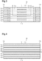
Fig. 3 is a cross-sectional view taken along line 3-3 inFig. 2 . -
Fig. 4 is a cross-sectional view taken along line 4-4 inFig. 2 . -
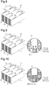
Fig. 5 is a diagram illustrating a molding step. -
Fig. 6 is a diagram illustrating a processing step (a diagram illustrating a state in which a processing jig for a first process is stuck in a molded body). -
Fig. 7 is a diagram illustrating the processing step (a diagram illustrating a state in which the processing jig for the first process is stuck in and then pulled out of the molded body). -
Fig. 8 is a diagram illustrating the processing step (a diagram illustrating a second process). -
Fig. 9 is a diagram illustrating a degreasing step. -
Fig. 10 is a diagram illustrating an impregnation step. - One embodiment of a heat exchanger will now be described.
- As shown in
Figs. 1 and 2 , aheat exchanger 10 of the present embodiment includes anouter wall 11 andpartition walls 12. Theouter wall 11 has the form of a rectangular tube. Thepartition walls 12 partition the inner side of theouter wall 11 into a plurality offirst cells 13a and a plurality ofsecond cells 13b extending in an axial direction of theouter wall 11. Theouter wall 11, which has the form of a rectangular tube, includes two opposingvertical side walls 11a and two opposinglateral side walls 11b. Theouter wall 11 is configured so that its cross section orthogonal to the axial direction is rectangular and laterally elongated. - As shown in
Fig. 2 , in a cross section orthogonal to the axial direction of theouter wall 11, thepartition walls 12 form a grid-like cell structure and includepartition walls 12 parallel to thevertical side walls 11a andpartition walls 12 parallel to thelateral side walls 11b. The cell structure of thepartition walls 12 is not particularly limited. For example, the cell structure may be configured so that thepartition walls 12 have a thickness of 0.1 to 0.5 mm and a cell density of 15 to 93 cells per 1 cm2 in a cross section orthogonal to the axial direction of theouter wall 11. - As shown in
Fig. 3 , thefirst cells 13a, through which a first fluid flows, each include two ends that are sealed by a sealedportion 22. As shown inFig. 4 , eachsecond cell 13b, through which a second fluid flows, includes two open ends. - The first fluid is not particularly limited and a known heat medium may be used. Examples of known heat medium include a coolant (long life coolant (LLC)) and an organic solvent, such as ethylene glycol. The second fluid is not particularly limited, and exhaust gas of an internal combustion engine may be used.
- As shown in
Fig. 2 , in a cross section orthogonal to the axial direction of theouter wall 11, eachfirst cell 13a has the same cross-sectional shape as thesecond cells 13b. - As shown in
Fig. 2 , theheat exchanger 10 includes a plurality offirst cell lines 14a and a plurality ofsecond cell lines 14b. Thefirst cell lines 14a include only thefirst cells 13a arranged parallel to thevertical side walls 11a of theouter wall 11, and thesecond cell lines 14b include only thesecond cells 13b arranged parallel to thevertical side walls 11a. In the present embodiment, foursecond cell lines 14b are arranged between two adjacentfirst cell lines 14a. This arrangement is repeated to form a pattern. - As shown in
Figs. 1 and3 , in theheat exchanger 10, thefirst cell lines 14a each include aconnection portion 15 extending in a vertical direction, which extends along thevertical side walls 11a. Theconnection portion 15 extends through thepartition walls 12 between adjacentfirst cells 13a in the vertical direction and connects the cells of thefirst cell lines 14a. Theconnection portion 15 has an end at one side in the vertical direction (upper side inFig. 3 ) that opens in the outer wall 11 (lateral side wall 11b) and an end at the other side in the vertical direction (lower side inFig. 3 ) reaching thefirst cell 13a that is the farthest from the opening of theconnection portion 15. In other words, eachconnection portion 15 opens in one side of theouter wall 11 and extends to thefirst cell 13a that is the farthest from the opening of theconnection portion 15. Theconnection portion 15 of theheat exchanger 10 includes afirst connection portion 15a and asecond connection portion 15b. Thefirst connection portion 15a is arranged closer to a first end 10a, which is located at one side in the axial direction of theheat exchanger 10, and thesecond connection portion 15b is arranged closer to asecond end 10b, which is located at the other side in the axial direction of theheat exchanger 10. - As shown in
Fig. 3 , afirst passage 16 is formed inside theheat exchanger 10 by thefirst cells 13a, thefirst connection portion 15a, and thesecond connection portion 15b. The opening of thefirst connection portion 15a and the opening of thesecond connection portion 15b in theouter wall 11 of the heat exchanger function as an inlet or an outlet of thefirst passage 16. Further, as shown inFig. 4 , asecond passage 17 is formed inside theheat exchanger 10 by eachsecond cell 13b with the first end 10a and thesecond end 10b of theouter wall 11 functioning as an inlet or an outlet of thesecond passage 17. Theheat exchanger 10 exchanges heat through thepartition walls 12 between the first fluid flowing through thefirst passages 16 and the second fluid flowing through thesecond passages 17. - The material of the
outer wall 11 and thepartition walls 12 of theheat exchanger 10 and a surface shape of theouter wall 11 and thepartition walls 12 will now be described. In the present embodiment, theouter wall 11 and thepartition walls 12 are formed from the same material and have the same surface shape. Thus, hereinafter, thepartition walls 12 will be described in detail and theouter wall 11 will not be described. - As shown in
Fig. 1 , thepartition walls 12 include aframe portion 12a having a porous structure and a fillingportion 12b. The fillingportion 12b covers the surface of theframe portion 12a and is formed from a metal that fills the voids in theframe portion 12a. Theframe portion 12a includes silicon carbide as a main component. Here, "main component" refers to a component that is greater than or equal to 50% by mass. Theframe portion 12a may include a component other than silicon carbide. An example of a component other than silicon carbide may be a ceramic material including a carbide, such as tantalum carbide and tungsten carbide, or a nitride, such as silicon nitride and boron nitride. When a component other than silicon carbide is included, the component may be of a single type or two or more types. - The metal forming the filling
portion 12b may be, for example, metal silicon, aluminum, iron, or copper. Among these substances, metal silicon is particularly preferred. The metal forming the fillingportion 12b may be of a single type or two or more types. - Preferably, a volume ratio of the
frame portion 12a to the fillingportion 12b (frame portion : filling portion) in thepartition walls 12 is, for example, 60:40 to 40:60. Preferably, the volume of the metal forming the fillingportion 12b is greater than the pore volume and, more preferably, 1.01 to 1.1 times the pore volume. When the volume of the metal is 1.01 times or greater than the pore volume, the surface roughness of the partition walls is increased. When the volume of the metal is less than or equal to 1.1 times the pore volume, metal is prevented from being deposited on the surfaces of the partition walls and the outer wall. - The filling
portion 12b forms the surfaces of thepartition walls 12. Preferably, thepartition walls 12 have a surface roughness (arithmetic mean surface roughness: Ra) that is greater than or equal to 1.0 µm and less than or equal to 1.2 µm. Further, it is preferred that the surface roughness of thepartition walls 12 is 5.0 µm or less. The surface roughness of thepartition walls 12 can be adjusted by changing a condition for forming the fillingportion 12b by impregnating theporous frame portion 12a with metal. - A method for measuring the surface roughness Ra will now be described.
- Samples that are 10 mm × 10 mm plates are cut out from the partition walls of the heat exchanger. The surface roughness Ra of the sample is measured by a roughness measurement instrument (e.g., Surfcom1400d, manufactured by TOKYO SEIMITSU) over a measurement span of 2 mm in a longitudinal direction of the passage. The same measurement is performed three times to obtain the mean value of the measurements.
- A method for manufacturing the heat exchanger of the present embodiment will now be described with reference to
Figs. 5 to 10 . The heat exchanger is manufactured by sequentially performing a molding step, a processing step, a degreasing step, and an impregnation step as described below. - As a raw material for molding the heat exchanger, silicon carbide particles, an organic binder, and a dispersion medium are mixed to prepare a clay-like mixture. In this case, particles of a component other than silicon carbide, such as ceramic particles, may be mixed if necessary.
- Preferably, the silicon carbide particles and the particles of components other than silicon carbide have an average particle size (50% particle diameter) of, for example, 0.5 to 50 µm.
- Examples of the organic binder include, for example, polyvinyl alcohol, methyl cellulose, ethyl cellulose, and carboxymethyl cellulose. Among these organic binders, methyl cellulose and carboxymethyl cellulose are particularly preferred. The organic binder may be of a single type or a combination of two or more types of the above.
- Examples of the dispersion medium include water and an organic solvent. The organic solvent is, for example, ethanol. The dispersion medium may be of a single type or a combination of two or more types of the above.
- Another component may further be included in the mixture. The other component may be, for example, a plasticizer or a lubricant. Examples of the plasticizer include a polyoxyalkylene compound, such as polyoxyethylene alkyl ether and polyoxypropylene alkyl ether. The lubricant is, for example, glycerol.
- A molded
body 20 shown inFig. 5 is molded from the clay-like mixture. The moldedbody 20 includes theouter wall 11, which has the form of a rectangular tube, and thepartition walls 12, which partition the inner side of theouter wall 11 into a plurality ofcells 13 extending in the axial direction of theouter wall 11. Thecells 13 in the moldedbody 20 each have two open ends. The moldedbody 20 can be molded, for example, by extrusion molding. A drying process is performed on the obtained moldedbody 20 to dry the moldedbody 20. - In the processing step, a first process and a second process are performed. The first process is performed to form first connection portions and second connection portions in the molded body. The second process is performed to seal the two ends in some of the cells of the molded body.
- As shown in
Fig. 6 , in the first process, for example, thefirst connection portions 15a and thesecond connection portions 15b are formed by aheated processing tool 21 that contacts the molded body and removes parts of theouter wall 11 and thepartition walls 12 of the moldedbody 20. - Specifically, as shown in
Fig. 6 , a blade having a contour that corresponds to thefirst connection portion 15a and thesecond connection portion 15b is prepared as theprocessing tool 21. The blade is formed from a heat resistant metal (e.g., stainless steel) and has a thickness that is set so as not to exceed the width of thefirst cell 13a. Subsequently, the blade is heated to a temperature that burns and removes the organic binder included in the moldedbody 20. For example, when the organic binder is methyl cellulose, the blade is heated to 400°C or higher. - As shown in
Fig. 7 , the heated blade is stuck into the moldedbody 20 from an outer side and then pulled out to form thefirst connection portions 15a and thesecond connection portions 15b. In this case, when the heated blade contacts the moldedbody 20, the organic binder included in the moldedbody 20 is burned and removed at the contact portion. Thus, the insertion resistance of the moldedbody 20 against the blade is extremely small. This limits deformation and breakage around the portion where the blade is stuck. Further, the burned and removed organic binder reduces the amount of processing waste. - As shown in
Fig. 8 , in the second process, among thecells 13 of the moldedbody 20, two ends of eachcell 13 defining afirst cell 13a are sealed with the clay-like mixture used in the molding step. This forms the sealedportions 22 that seal the two ends of thecell 13. Then, a drying process is performed on the moldedbody 20 to dry the sealedportions 22. - A processed molded body is obtained by performing the processing step including the first process and the second process. The order in which the first process and the second process are performed is not particularly limited. The first process may be performed after the second process.
- In the degreasing step, the processed molded body is heated to burn and remove the organic binder included in the processed molded body. This removes the organic binder from the processed molded body and obtains a degreased body. As shown in
Fig. 9 , the degreasedbody 30, which is obtained by removing the organic binder from the processed molded body in the degreasing step, has a porous structure including voids between particles of silicon carbide. Preferably, a volume of the voids (pore volume) in the degreasedbody 30 is 40% to 60% by volume. The pore volume of the degreasedbody 30 can be adjusted by changing a content rate of the silicon carbide particles in the mixture used in the molding step. - In the impregnation step, the inner side of each wall forming the degreased body is impregnated with a metal, such as metal silicon. The impregnation step includes heating the degreased body in a state contacting a cluster of the metal to the melting point of the metal or higher (for example, when metal silicon is used, 1450°C or higher) in an inert gas atmosphere, such as argon or nitrogen, or in a vacuum. As shown in
Fig. 10 , molten metal enters the voids between particles forming the degreased body by a capillary action and impregnates the voids. The portion of the degreased body where the cluster of metal comes into contact is not particularly limited. From the viewpoint of the efficiency, it is preferred that the cluster of metal comes into contact with the upper part of the degreased body. - When metal silicon is used, it is preferred that metal silicon having a purity of less than 98% is used. The melting point of metal silicon (cluster of metal silicon) tends to be lower as the purity decreases. Thus, use of metal silicon having a low purity can lower the heating temperature required by the impregnation step. This decreases the manufacturing cost. The purity of metal silicon is, for example, 95% or higher.
- The amount of metal cluster that contacts the degreased body (preparation amount of metal filling degreased body) is set to be greater than the amount corresponding to the pore volume of the degreased
body 30, or less than the amount corresponding to the pore volume of the degreasedbody 30. Specifically, the preparation amount of metal is set to an amount corresponding to 1.01 to 1.1 times the pore volume of the degreasedbody 30. - When the preparation amount of metal is set to be greater than the amount corresponding to the pore volume of the degreased
body 30, part of the impregnating metal will overflow the pores in the degreasedbody 30 and form projections on the surface. This increases the surface roughness of the formed outer wall and partition walls. When the preparation amount of metal is set to be less than the amount corresponding to the pore volume of the degreasedbody 30, irregularities resulting from the pores of the degreasedbody 30 will be produced in the surface of the formed outer wall and partition walls. This increases the surface roughness of the formed outer wall and partition walls. - The heating process in the impregnation step may be performed successively with the heating process of the degreasing step. For example, in a state contacting a cluster of metal silicon, the processed molded body may be heated at a temperature lower than the melting point of metal silicon to remove the organic binder and obtain the degreased body. Then, the heating temperature may be raised to the melting point of the metal silicon or higher to impregnate the degreased body with the molten metal silicon.
- The heat exchanger is obtained by performing the impregnation step.
- In the present embodiment, special temperature management is performed in the steps from the degreasing step. Specifically, the steps from the degreasing step are performed at a lower temperature than a sintering temperature of the silicon carbide included in the mixture used in the molding step so that the processed molded body and the degreased body are not exposed to a temperature higher than or equal to the sintering temperature. Therefore, in the degreasing step, heating is performed at a temperature that is higher than or equal to a temperature that burns and removes the organic binder and lower than the sintering temperature. In the same manner, in the impregnation step, heating is performed at a temperature higher than or equal to the melting point of the metal and lower than the sintering temperature.
- The operation and advantages of the present embodiment will now be described.
- (1) The heat exchanger includes the first cells through which the first fluid flows, the second cells through which the second fluid flows, and the partition walls that partition the first cells and the second cells. The partition walls include the frame portion, which has silicon carbide as a main component, and the filling portion, which covers the surface of the frame portion and is formed from a metal that fills the voids in the frame portion. The partition walls have the surface roughness Ra of 1.0 µm or greater.
The above structure increases the area of contact between fluid and the partition walls when the first fluid and the second fluid are flowing. This increases the heat exchange efficiency between the fluids and the partition walls and increases the heat exchange efficiency of the heat exchanger. - (2) The filling portion is formed from metal silicon.
The filling portion, which is formed from metal silicon, increases the thermal conductivity of the partition walls and increases the heat exchange efficiency. Further, the difference in coefficient of thermal expansion is small between metal silicon and silicon carbide, which forms the frame portion. This prevents damages caused by thermal shocks during use. - (3) The surface roughness Ra of the partition walls is 5.0 µm or less.
The above structure avoids a situation in which the surface shape of the partition walls causes the first fluid and the second fluid flowing along the partition walls to become turbulent flows and limits increases in the flow resistance. - (4) The method for manufacturing a heat exchanger that includes the first cells through which the first fluid flows, the second cells through which the second fluid flows, and the partition walls that partition the first cells and the second cells includes the molding step, the degreasing step, and the impregnation step. The molding step molds a molded body from a mixture of silicon carbide particles, an organic binder, and a dispersion medium. The degreasing step removes the organic binder included in the molding body to obtain a porous degreased body. The impregnation step impregnates the inner side of the degreased body with a metal. In the impregnation step, the degreased body is heated in a state contacting a cluster of metal to a melting point of the metal or higher for impregnation of the metal of an amount equivalent to 1.01 to 1.1 times the pore volume of the degreased body.
Generally, partition walls formed by impregnating a porous body of silicon carbide with a metal such as metal silicon have a dense structure. Thus, the surfaces of the partition walls tend to be smooth and have few asperities. In particular, as Patent Document 1 discloses, when the partition walls are formed by placing a porous body of silicon carbide in a metal silicon atmosphere and vapor-depositing metal silicon, the partition walls are likely to have smooth surfaces. This is because metal silicon exists in extremely small units and hinders the formation of asperities after vapor-deposition. In this respect, the above-described structure increases the surface roughness of the partition walls even when the partition walls are formed by impregnating a porous body of silicon carbide with a metal. - (5) The metal that impregnates the inner side of the degreased body is metal silicon.
Metal silicon has an acceptable wettability for silicon carbide that forms the frame portion. This allows metal silicon to fill the voids between the silicon carbide particles without gaps. - (6) In the impregnation step, the degreased body is heated in a state in which a cluster of metal is placed on the degreased body.
The above structure allows for effective impregnation of a metal by using the effect in which the molten metal flows down the walls of the degreased body. - (7) The heat exchanger of the present embodiment is manufactured by performing temperature management as described above. The frame portion is formed in a state in which the silicon carbide particles are in contact with one another, and the shape of the frame portion is held with the voids filled with the silicon carbide. In other words, the silicon carbide particles do not include connected portions (necks), which result from sintering. This prevents cracking of necks between the silicon carbide particles even when internal temperature differences cause distortion in the partition walls during use of the heat exchanger. This further prevents cracks from spreading through necks.
- The present embodiment may be modified as described below. Also, the configuration of the above embodiment and following modifications may be combined.
- The shape of the heat exchanger (for example, outer shape of heat exchanger or cell shape) is not limited to that of the above embodiment and may be changed.
- In the above embodiment, the partition walls and the outer wall include the frame portion and the filling portion and the surface roughness Ra is configured to be 1.0 µm or greater. However, this does not limit the material of the outer wall or the surface shape of the outer wall.
- Part of or all of the processing step may be omitted from the method for manufacturing the heat exchanger. The processing step is performed so that the shape of the molded body, which is obtained in the molding step, becomes close to the shape of the manufactured heat exchanger. Thus, the processing step may include only the processes that are necessary for shaping the manufactured heat exchanger and the molded body. Further, the processing step may include a process other than the first process and the second process as long as the process for removing part of the molded body is performed by a processing tool, which is heated to a temperature that burns and removes the organic binder and contacts the molded body.
- The method for manufacturing the heat exchanger may further include a step other than the molding step, the processing step, the degreasing step, and the impregnation step. For example, a surface machining, such as polishing, may be performed after the impregnation step. Preferably, a process after the degreasing step is performed in the same manner as the impregnation step at a temperature lower than or equal to a predetermined temperature.
- Specific examples of the above described embodiment will now be described.
- First, a mixture having the composition described below was prepared.
- Silicon carbide particles with average particle size of 15 µm (large particles): 52.5 parts by mass
Silicon carbide particles with average particle size of 0.5 µm (small particles): 23.6 parts by mass
Methyl cellulose (organic binder): 5.4 parts by mass
Glycerol (lubricant): 1.1 parts by mass
Polyoxyalkylene compound (plasticizer): 3.2 parts by mass
Water (dispersion medium): 11.5 parts by mass
With this mixture, a molded body was molded to have the same shape as one shown inFig. 5 , in which the height was 50 mm, the width was 100 mm, the length was 100 mm, the thickness of the outer wall was 0.3 mm, the thickness of the partition walls was 0.25 mm, and the cell width was 1.2 mm. - Next, a plate-like jig heated to 400°C was stuck into the outer wall of the molded body to form the first connection portions and the second connection portions. Then, predetermined cells were sealed with a clay-like mixture having the same composition as the above mixture to form the processed molded body including first cells and second cells. Subsequently, the processed molded body was heated at 450°C for five hours to remove the organic binder and obtain the degreased body. Then, the degreased body was heated at 1550°C for seven hours in a vacuum in a state in which 153 g (preparation amount: amount corresponding to 1.05 times pore volume of degreased body) of metal silicon plate is placed on the degreased body to impregnate the degreased body with metal silicon and obtain a heat exchanger of example 1.
- A heat exchanger of example 2 was obtained in the same manner as example 1 except in that the amount (preparation amount) of metal silicon plate was set to 147.2 g (amount corresponding to 1.01 times pore volume of degreased body).
- A heat exchanger of example 3 was obtained in the same manner as example 1 except in that the amount (preparation amount) of metal silicon plate was set to 160.3 g (amount corresponding to 1.1 times pore volume of degreased body).
- A heat exchanger of a comparative example was obtained in the same manner as example 1 except in that the amount (preparation amount) of metal silicon plate was set to 145.7 g (amount corresponding to 1.0 times pore volume of degreased body).
- The partition wall was cut out as a measurement sample over
width 10 mm ×length 10 mm from each example and the comparative example of the heat exchanger. The surface roughness (arithmetic mean surface roughness: Ra) of the measurement samples were measured using a surface roughness measurement instrument. As the surface roughness measurement instrument, Surfcom1400d, manufactured by TOKYO SEIMITSU, was used. The results are shown in Table 1. - With each example and the comparative example of the heat exchanger, a coolant, which was 40°C, was charged through the inlet into the first cells at a flow rate of 10 L/min and a high temperature gas, which was 400°C, was charged through the inlet into the second cells at a flow rate of 10 g/sec. Then, the temperature difference in the coolant at the inlet and the outlet was measured to obtain the exhaust heat recovery amount for each heat exchanger. The results are shown in Table 1.
Table 1 Preparation Amount of Metal Silicon (Volume Ratio to Pore Volume of Degreased Body) Surface Roughness Ra Exhaust Heat Recovery Amount Example 1 1.05× 2.0 µm 3.4 kW Example 2 1.01× 1.0 µm 3.1 kW Example 3 1.1x 4.5 µm 3.3 kW Comparative Example 1.0× 0.5 µm 2.9 kW - As shown in Table 1, in the comparative example in which the preparation amount of the metal silicon in the impregnation step corresponded to 1.0 times the pore volume of the degreased body, the surface roughness of the partition walls was 0.5 µm. In contrast, in examples 1 to 3, in which the preparation amount of the metal silicon in the impregnation step was set to be greater than the pore volume of the degreased body, the surface roughness of the partition walls was 1.0 to 4.5 µm. From the results, it is indicated that the surface roughness of the partition walls can be increased by increasing the preparation amount of metal silicon from the pore volume of the degreased body.
- Also, from the results of examples 1 to 3, it can be confirmed that when the surface roughness Ra of the partition walls is increased, the area of contact between the fluids and the partition walls is increased thereby increasing the exhaust heat recovery amount. This indicates that the heat exchange efficiency can be increased by increasing the surface roughness Ra of the partition walls.
- 10) heat exchanger, 11) outer wall, 12) partition wall, 12a) frame portion, 12b) filling portion, 13a) first cell, 13b) second cell, 20) molded body, 30) degreased body.
Claims (5)
- A heat exchanger, comprising:first cells through which a first fluid flows;second cells through which a second fluid flows; andpartition walls that partition the first cells and the second cells, whereinthe heat exchanger exchanges heat between the first fluid and the second fluid,the partition walls include a frame portion having silicon carbide as a main component and a filling portion that covers a surface of the frame portion and is formed from a metal that fills a void in the frame portion, andthe partition walls have a surface roughness Ra of 1.0 µm or greater.
- The heat exchanger according to claim 1, wherein the metal is metal silicon.
- The heat exchanger according to claim 1 or 2, wherein the surface roughness Ra of the partition walls is 5.0 µm or less.
- A method for manufacturing a heat exchanger, wherein the heat exchanger includes first cells through which a first fluid flows, second cells through which a second fluid flows, and partition walls that partition the first cells and the second cells and exchanges heat between the first fluid and the second fluid, the method comprising:a molding step for molding a molded body from a mixture including silicon carbide particles, an organic binder, and a dispersion medium;a degreasing step for removing the organic binder included in the molded body to obtain a porous degreased body; andan impregnation step for impregnating an inner side of the degreased body with a metal,wherein the impregnation step includes heating the degreased body in a state contacting a cluster of metal to a melting point of the metal or higher for impregnation of the metal of an amount equivalent to 1.01 to 1.1 times a pore volume of the degreased body.
- The method for manufacturing a heat exchanger according to claim 4, wherein the metal is metal silicon.
Applications Claiming Priority (2)
| Application Number | Priority Date | Filing Date | Title |
|---|---|---|---|
| JP2017201114A JP6854229B2 (en) | 2017-10-17 | 2017-10-17 | Heat exchanger |
| PCT/JP2018/038573 WO2019078225A1 (en) | 2017-10-17 | 2018-10-17 | Heat exchanger and production method for heat exchanger |
Publications (2)
| Publication Number | Publication Date |
|---|---|
| EP3699540A1 true EP3699540A1 (en) | 2020-08-26 |
| EP3699540A4 EP3699540A4 (en) | 2021-06-09 |
Family
ID=66173395
Family Applications (1)
| Application Number | Title | Priority Date | Filing Date |
|---|---|---|---|
| EP18867798.3A Withdrawn EP3699540A4 (en) | 2017-10-17 | 2018-10-17 | Heat exchanger and production method for heat exchanger |
Country Status (5)
| Country | Link |
|---|---|
| US (1) | US20200318917A1 (en) |
| EP (1) | EP3699540A4 (en) |
| JP (1) | JP6854229B2 (en) |
| CN (1) | CN111213026A (en) |
| WO (1) | WO2019078225A1 (en) |
Family Cites Families (6)
| Publication number | Priority date | Publication date | Assignee | Title |
|---|---|---|---|---|
| JP4060822B2 (en) * | 2004-04-16 | 2008-03-12 | 日本碍子株式会社 | Ceramic composite material |
| JP2010271031A (en) * | 2009-04-23 | 2010-12-02 | Ngk Insulators Ltd | Ceramics heat exchanger and method of manufacturing the same |
| JP6324150B2 (en) * | 2013-07-23 | 2018-05-16 | 日本碍子株式会社 | Heat exchange member and ceramic structure |
| JP6158687B2 (en) * | 2013-11-05 | 2017-07-05 | 日本碍子株式会社 | Heat exchange member |
| JP6404691B2 (en) * | 2014-11-27 | 2018-10-10 | 日本碍子株式会社 | Heat exchange parts |
| JP2017170645A (en) * | 2016-03-18 | 2017-09-28 | イビデン株式会社 | Method for producing honeycomb structure |
-
2017
- 2017-10-17 JP JP2017201114A patent/JP6854229B2/en not_active Expired - Fee Related
-
2018
- 2018-10-17 CN CN201880066984.XA patent/CN111213026A/en active Pending
- 2018-10-17 US US16/756,120 patent/US20200318917A1/en not_active Abandoned
- 2018-10-17 WO PCT/JP2018/038573 patent/WO2019078225A1/en not_active Ceased
- 2018-10-17 EP EP18867798.3A patent/EP3699540A4/en not_active Withdrawn
Also Published As
| Publication number | Publication date |
|---|---|
| JP2019074266A (en) | 2019-05-16 |
| WO2019078225A1 (en) | 2019-04-25 |
| US20200318917A1 (en) | 2020-10-08 |
| EP3699540A4 (en) | 2021-06-09 |
| CN111213026A (en) | 2020-05-29 |
| JP6854229B2 (en) | 2021-04-07 |
Similar Documents
| Publication | Publication Date | Title |
|---|---|---|
| EP3466910B1 (en) | Honeycomb structure production method | |
| US7348049B2 (en) | Honeycomb structural body, manufacturing method of the honeycomb structural body, and exhaust gas purifying device | |
| CN101146589A (en) | Honeycomb filter | |
| WO2007102217A1 (en) | Fired body cooler, firing furnace, method of cooling ceramic fired body, and process for producing honeycomb structure | |
| EP3766858B1 (en) | Method for producing honeycomb structure | |
| CN105940212A (en) | Castings and inserts for such castings | |
| WO2019176898A1 (en) | Heat exchanger production method | |
| EP3466906A1 (en) | Honeycomb structure | |
| US20200318917A1 (en) | Heat exchanger and production method for heat exchanger | |
| WO2017159306A1 (en) | Method for producing honeycomb structure | |
| JP3935159B2 (en) | Ceramic honeycomb filter | |
| EP3699536A1 (en) | Heat exchanger | |
| JP2021025730A (en) | Heat exchanger | |
| JP6956050B2 (en) | How to make a heat exchanger | |
| JP2021025732A (en) | Heat exchanger | |
| US12623367B2 (en) | Method and device for producing honeycomb structure | |
| JP7018342B2 (en) | Heat exchanger | |
| US12497337B2 (en) | Method for manufacturing metal-impregnated ceramic fired body | |
| US20240327295A1 (en) | Ceramic body and method for producing same | |
| JP7532703B1 (en) | Molten metal filtration unit | |
| JP7635022B2 (en) | Manufacturing method of honeycomb structure | |
| JP6857589B2 (en) | Heat exchanger | |
| JP2019174012A (en) | Heat exchanger | |
| WO2019078226A1 (en) | Heat exchanger | |
| CN116470083A (en) | Water-cooled hydrogen fuel cell bipolar plate and preparation method thereof |
Legal Events
| Date | Code | Title | Description |
|---|---|---|---|
| STAA | Information on the status of an ep patent application or granted ep patent |
Free format text: STATUS: THE INTERNATIONAL PUBLICATION HAS BEEN MADE |
|
| PUAI | Public reference made under article 153(3) epc to a published international application that has entered the european phase |
Free format text: ORIGINAL CODE: 0009012 |
|
| STAA | Information on the status of an ep patent application or granted ep patent |
Free format text: STATUS: REQUEST FOR EXAMINATION WAS MADE |
|
| 17P | Request for examination filed |
Effective date: 20200415 |
|
| AK | Designated contracting states |
Kind code of ref document: A1 Designated state(s): AL AT BE BG CH CY CZ DE DK EE ES FI FR GB GR HR HU IE IS IT LI LT LU LV MC MK MT NL NO PL PT RO RS SE SI SK SM TR |
|
| AX | Request for extension of the european patent |
Extension state: BA ME |
|
| DAV | Request for validation of the european patent (deleted) | ||
| DAX | Request for extension of the european patent (deleted) | ||
| A4 | Supplementary search report drawn up and despatched |
Effective date: 20210511 |
|
| RIC1 | Information provided on ipc code assigned before grant |
Ipc: F28F 21/04 20060101AFI20210505BHEP Ipc: C04B 35/569 20060101ALI20210505BHEP Ipc: F28D 7/00 20060101ALI20210505BHEP Ipc: F28D 21/00 20060101ALI20210505BHEP Ipc: F28F 13/02 20060101ALI20210505BHEP Ipc: F28F 21/08 20060101ALI20210505BHEP Ipc: F28F 7/02 20060101ALI20210505BHEP |
|
| STAA | Information on the status of an ep patent application or granted ep patent |
Free format text: STATUS: THE APPLICATION HAS BEEN WITHDRAWN |
|
| 18W | Application withdrawn |
Effective date: 20211117 |