EP3699451A1 - Stroke sensor system and shock absorber - Google Patents
Stroke sensor system and shock absorber Download PDFInfo
- Publication number
- EP3699451A1 EP3699451A1 EP17929029.1A EP17929029A EP3699451A1 EP 3699451 A1 EP3699451 A1 EP 3699451A1 EP 17929029 A EP17929029 A EP 17929029A EP 3699451 A1 EP3699451 A1 EP 3699451A1
- Authority
- EP
- European Patent Office
- Prior art keywords
- coil
- cylinder
- collar
- shock absorber
- sensor system
- Prior art date
- Legal status (The legal status is an assumption and is not a legal conclusion. Google has not performed a legal analysis and makes no representation as to the accuracy of the status listed.)
- Granted
Links
Images




Classifications
-
- B—PERFORMING OPERATIONS; TRANSPORTING
- B60—VEHICLES IN GENERAL
- B60G—VEHICLE SUSPENSION ARRANGEMENTS
- B60G13/00—Resilient suspensions characterised by arrangement, location or type of vibration dampers
- B60G13/02—Resilient suspensions characterised by arrangement, location or type of vibration dampers having dampers dissipating energy, e.g. frictionally
- B60G13/06—Resilient suspensions characterised by arrangement, location or type of vibration dampers having dampers dissipating energy, e.g. frictionally of fluid type
- B60G13/08—Resilient suspensions characterised by arrangement, location or type of vibration dampers having dampers dissipating energy, e.g. frictionally of fluid type hydraulic
-
- B—PERFORMING OPERATIONS; TRANSPORTING
- B60—VEHICLES IN GENERAL
- B60G—VEHICLE SUSPENSION ARRANGEMENTS
- B60G15/00—Resilient suspensions characterised by arrangement, location or type of combined spring and vibration damper, e.g. telescopic type
- B60G15/02—Resilient suspensions characterised by arrangement, location or type of combined spring and vibration damper, e.g. telescopic type having mechanical spring
- B60G15/06—Resilient suspensions characterised by arrangement, location or type of combined spring and vibration damper, e.g. telescopic type having mechanical spring and fluid damper
- B60G15/062—Resilient suspensions characterised by arrangement, location or type of combined spring and vibration damper, e.g. telescopic type having mechanical spring and fluid damper the spring being arranged around the damper
-
- B—PERFORMING OPERATIONS; TRANSPORTING
- B60—VEHICLES IN GENERAL
- B60G—VEHICLE SUSPENSION ARRANGEMENTS
- B60G15/00—Resilient suspensions characterised by arrangement, location or type of combined spring and vibration damper, e.g. telescopic type
- B60G15/02—Resilient suspensions characterised by arrangement, location or type of combined spring and vibration damper, e.g. telescopic type having mechanical spring
- B60G15/06—Resilient suspensions characterised by arrangement, location or type of combined spring and vibration damper, e.g. telescopic type having mechanical spring and fluid damper
- B60G15/062—Resilient suspensions characterised by arrangement, location or type of combined spring and vibration damper, e.g. telescopic type having mechanical spring and fluid damper the spring being arranged around the damper
- B60G15/063—Resilient suspensions characterised by arrangement, location or type of combined spring and vibration damper, e.g. telescopic type having mechanical spring and fluid damper the spring being arranged around the damper characterised by the mounting of the spring on the damper
-
- B—PERFORMING OPERATIONS; TRANSPORTING
- B62—LAND VEHICLES FOR TRAVELLING OTHERWISE THAN ON RAILS
- B62K—CYCLES; CYCLE FRAMES; CYCLE STEERING DEVICES; RIDER-OPERATED TERMINAL CONTROLS SPECIALLY ADAPTED FOR CYCLES; CYCLE AXLE SUSPENSIONS; CYCLE SIDECARS, FORECARS, OR THE LIKE
- B62K25/00—Axle suspensions
- B62K25/04—Axle suspensions for mounting axles resiliently on cycle frame or fork
-
- F—MECHANICAL ENGINEERING; LIGHTING; HEATING; WEAPONS; BLASTING
- F16—ENGINEERING ELEMENTS AND UNITS; GENERAL MEASURES FOR PRODUCING AND MAINTAINING EFFECTIVE FUNCTIONING OF MACHINES OR INSTALLATIONS; THERMAL INSULATION IN GENERAL
- F16F—SPRINGS; SHOCK-ABSORBERS; MEANS FOR DAMPING VIBRATION
- F16F1/00—Springs
- F16F1/02—Springs made of steel or other material having low internal friction; Wound, torsion, leaf, cup, ring or the like springs, the material of the spring not being relevant
- F16F1/04—Wound springs
- F16F1/12—Attachments or mountings
-
- F—MECHANICAL ENGINEERING; LIGHTING; HEATING; WEAPONS; BLASTING
- F16—ENGINEERING ELEMENTS AND UNITS; GENERAL MEASURES FOR PRODUCING AND MAINTAINING EFFECTIVE FUNCTIONING OF MACHINES OR INSTALLATIONS; THERMAL INSULATION IN GENERAL
- F16F—SPRINGS; SHOCK-ABSORBERS; MEANS FOR DAMPING VIBRATION
- F16F9/00—Springs, vibration-dampers, shock-absorbers, or similarly-constructed movement-dampers using a fluid or the equivalent as damping medium
- F16F9/10—Springs, vibration-dampers, shock-absorbers, or similarly-constructed movement-dampers using a fluid or the equivalent as damping medium using liquid only; using a fluid of which the nature is immaterial
- F16F9/14—Devices with one or more members, e.g. pistons, vanes, moving to and fro in chambers and using throttling effect
- F16F9/16—Devices with one or more members, e.g. pistons, vanes, moving to and fro in chambers and using throttling effect involving only straight-line movement of the effective parts
- F16F9/18—Devices with one or more members, e.g. pistons, vanes, moving to and fro in chambers and using throttling effect involving only straight-line movement of the effective parts with a closed cylinder and a piston separating two or more working spaces therein
- F16F9/19—Devices with one or more members, e.g. pistons, vanes, moving to and fro in chambers and using throttling effect involving only straight-line movement of the effective parts with a closed cylinder and a piston separating two or more working spaces therein with a single cylinder and of single-tube type
-
- F—MECHANICAL ENGINEERING; LIGHTING; HEATING; WEAPONS; BLASTING
- F16—ENGINEERING ELEMENTS AND UNITS; GENERAL MEASURES FOR PRODUCING AND MAINTAINING EFFECTIVE FUNCTIONING OF MACHINES OR INSTALLATIONS; THERMAL INSULATION IN GENERAL
- F16F—SPRINGS; SHOCK-ABSORBERS; MEANS FOR DAMPING VIBRATION
- F16F9/00—Springs, vibration-dampers, shock-absorbers, or similarly-constructed movement-dampers using a fluid or the equivalent as damping medium
- F16F9/32—Details
- F16F9/3292—Sensor arrangements
-
- F—MECHANICAL ENGINEERING; LIGHTING; HEATING; WEAPONS; BLASTING
- F16—ENGINEERING ELEMENTS AND UNITS; GENERAL MEASURES FOR PRODUCING AND MAINTAINING EFFECTIVE FUNCTIONING OF MACHINES OR INSTALLATIONS; THERMAL INSULATION IN GENERAL
- F16F—SPRINGS; SHOCK-ABSORBERS; MEANS FOR DAMPING VIBRATION
- F16F9/00—Springs, vibration-dampers, shock-absorbers, or similarly-constructed movement-dampers using a fluid or the equivalent as damping medium
- F16F9/32—Details
- F16F9/38—Covers for protection or appearance
-
- G—PHYSICS
- G01—MEASURING; TESTING
- G01B—MEASURING LENGTH, THICKNESS OR SIMILAR LINEAR DIMENSIONS; MEASURING ANGLES; MEASURING AREAS; MEASURING IRREGULARITIES OF SURFACES OR CONTOURS
- G01B7/00—Measuring arrangements characterised by the use of electric or magnetic techniques
- G01B7/003—Measuring arrangements characterised by the use of electric or magnetic techniques for measuring position, not involving coordinate determination
-
- G—PHYSICS
- G01—MEASURING; TESTING
- G01D—MEASURING NOT SPECIALLY ADAPTED FOR A SPECIFIC VARIABLE; ARRANGEMENTS FOR MEASURING TWO OR MORE VARIABLES NOT COVERED IN A SINGLE OTHER SUBCLASS; TARIFF METERING APPARATUS; MEASURING OR TESTING NOT OTHERWISE PROVIDED FOR
- G01D5/00—Mechanical means for transferring the output of a sensing member; Means for converting the output of a sensing member to another variable where the form or nature of the sensing member does not constrain the means for converting; Transducers not specially adapted for a specific variable
- G01D5/12—Mechanical means for transferring the output of a sensing member; Means for converting the output of a sensing member to another variable where the form or nature of the sensing member does not constrain the means for converting; Transducers not specially adapted for a specific variable using electric or magnetic means
- G01D5/14—Mechanical means for transferring the output of a sensing member; Means for converting the output of a sensing member to another variable where the form or nature of the sensing member does not constrain the means for converting; Transducers not specially adapted for a specific variable using electric or magnetic means influencing the magnitude of a current or voltage
- G01D5/20—Mechanical means for transferring the output of a sensing member; Means for converting the output of a sensing member to another variable where the form or nature of the sensing member does not constrain the means for converting; Transducers not specially adapted for a specific variable using electric or magnetic means influencing the magnitude of a current or voltage by varying inductance, e.g. by a movable armature
- G01D5/2006—Mechanical means for transferring the output of a sensing member; Means for converting the output of a sensing member to another variable where the form or nature of the sensing member does not constrain the means for converting; Transducers not specially adapted for a specific variable using electric or magnetic means influencing the magnitude of a current or voltage by varying inductance, e.g. by a movable armature by influencing the self-induction of one or more coils
- G01D5/2013—Mechanical means for transferring the output of a sensing member; Means for converting the output of a sensing member to another variable where the form or nature of the sensing member does not constrain the means for converting; Transducers not specially adapted for a specific variable using electric or magnetic means influencing the magnitude of a current or voltage by varying inductance, e.g. by a movable armature by influencing the self-induction of one or more coils by a movable ferromagnetic element, e.g. a core
-
- G—PHYSICS
- G01—MEASURING; TESTING
- G01D—MEASURING NOT SPECIALLY ADAPTED FOR A SPECIFIC VARIABLE; ARRANGEMENTS FOR MEASURING TWO OR MORE VARIABLES NOT COVERED IN A SINGLE OTHER SUBCLASS; TARIFF METERING APPARATUS; MEASURING OR TESTING NOT OTHERWISE PROVIDED FOR
- G01D5/00—Mechanical means for transferring the output of a sensing member; Means for converting the output of a sensing member to another variable where the form or nature of the sensing member does not constrain the means for converting; Transducers not specially adapted for a specific variable
- G01D5/12—Mechanical means for transferring the output of a sensing member; Means for converting the output of a sensing member to another variable where the form or nature of the sensing member does not constrain the means for converting; Transducers not specially adapted for a specific variable using electric or magnetic means
- G01D5/14—Mechanical means for transferring the output of a sensing member; Means for converting the output of a sensing member to another variable where the form or nature of the sensing member does not constrain the means for converting; Transducers not specially adapted for a specific variable using electric or magnetic means influencing the magnitude of a current or voltage
- G01D5/20—Mechanical means for transferring the output of a sensing member; Means for converting the output of a sensing member to another variable where the form or nature of the sensing member does not constrain the means for converting; Transducers not specially adapted for a specific variable using electric or magnetic means influencing the magnitude of a current or voltage by varying inductance, e.g. by a movable armature
- G01D5/2006—Mechanical means for transferring the output of a sensing member; Means for converting the output of a sensing member to another variable where the form or nature of the sensing member does not constrain the means for converting; Transducers not specially adapted for a specific variable using electric or magnetic means influencing the magnitude of a current or voltage by varying inductance, e.g. by a movable armature by influencing the self-induction of one or more coils
- G01D5/202—Mechanical means for transferring the output of a sensing member; Means for converting the output of a sensing member to another variable where the form or nature of the sensing member does not constrain the means for converting; Transducers not specially adapted for a specific variable using electric or magnetic means influencing the magnitude of a current or voltage by varying inductance, e.g. by a movable armature by influencing the self-induction of one or more coils by movable a non-ferromagnetic conductive element
-
- B—PERFORMING OPERATIONS; TRANSPORTING
- B60—VEHICLES IN GENERAL
- B60G—VEHICLE SUSPENSION ARRANGEMENTS
- B60G2202/00—Indexing codes relating to the type of spring, damper or actuator
- B60G2202/20—Type of damper
- B60G2202/24—Fluid damper
-
- B—PERFORMING OPERATIONS; TRANSPORTING
- B60—VEHICLES IN GENERAL
- B60G—VEHICLE SUSPENSION ARRANGEMENTS
- B60G2202/00—Indexing codes relating to the type of spring, damper or actuator
- B60G2202/30—Spring/Damper and/or actuator Units
- B60G2202/31—Spring/Damper and/or actuator Units with the spring arranged around the damper, e.g. MacPherson strut
- B60G2202/312—The spring being a wound spring
-
- B—PERFORMING OPERATIONS; TRANSPORTING
- B60—VEHICLES IN GENERAL
- B60G—VEHICLE SUSPENSION ARRANGEMENTS
- B60G2204/00—Indexing codes related to suspensions per se or to auxiliary parts
- B60G2204/10—Mounting of suspension elements
- B60G2204/12—Mounting of springs or dampers
- B60G2204/124—Mounting of coil springs
- B60G2204/1242—Mounting of coil springs on a damper, e.g. MacPerson strut
-
- B—PERFORMING OPERATIONS; TRANSPORTING
- B60—VEHICLES IN GENERAL
- B60G—VEHICLE SUSPENSION ARRANGEMENTS
- B60G2206/00—Indexing codes related to the manufacturing of suspensions: constructional features, the materials used, procedures or tools
- B60G2206/01—Constructional features of suspension elements, e.g. arms, dampers, springs
- B60G2206/40—Constructional features of dampers and/or springs
- B60G2206/41—Dampers
-
- B—PERFORMING OPERATIONS; TRANSPORTING
- B60—VEHICLES IN GENERAL
- B60G—VEHICLE SUSPENSION ARRANGEMENTS
- B60G2206/00—Indexing codes related to the manufacturing of suspensions: constructional features, the materials used, procedures or tools
- B60G2206/01—Constructional features of suspension elements, e.g. arms, dampers, springs
- B60G2206/70—Materials used in suspensions
- B60G2206/73—Rubber; Elastomers
-
- B—PERFORMING OPERATIONS; TRANSPORTING
- B60—VEHICLES IN GENERAL
- B60G—VEHICLE SUSPENSION ARRANGEMENTS
- B60G2300/00—Indexing codes relating to the type of vehicle
- B60G2300/12—Cycles; Motorcycles
-
- B—PERFORMING OPERATIONS; TRANSPORTING
- B60—VEHICLES IN GENERAL
- B60G—VEHICLE SUSPENSION ARRANGEMENTS
- B60G2400/00—Indexing codes relating to detected, measured or calculated conditions or factors
- B60G2400/25—Stroke; Height; Displacement
- B60G2400/252—Stroke; Height; Displacement vertical
-
- B—PERFORMING OPERATIONS; TRANSPORTING
- B60—VEHICLES IN GENERAL
- B60G—VEHICLE SUSPENSION ARRANGEMENTS
- B60G2401/00—Indexing codes relating to the type of sensors based on the principle of their operation
- B60G2401/17—Magnetic/Electromagnetic
-
- B—PERFORMING OPERATIONS; TRANSPORTING
- B60—VEHICLES IN GENERAL
- B60G—VEHICLE SUSPENSION ARRANGEMENTS
- B60G2800/00—Indexing codes relating to the type of movement or to the condition of the vehicle and to the end result to be achieved by the control action
- B60G2800/16—Running
- B60G2800/162—Reducing road induced vibrations
-
- B—PERFORMING OPERATIONS; TRANSPORTING
- B62—LAND VEHICLES FOR TRAVELLING OTHERWISE THAN ON RAILS
- B62K—CYCLES; CYCLE FRAMES; CYCLE STEERING DEVICES; RIDER-OPERATED TERMINAL CONTROLS SPECIALLY ADAPTED FOR CYCLES; CYCLE AXLE SUSPENSIONS; CYCLE SIDECARS, FORECARS, OR THE LIKE
- B62K25/00—Axle suspensions
- B62K25/04—Axle suspensions for mounting axles resiliently on cycle frame or fork
- B62K25/28—Axle suspensions for mounting axles resiliently on cycle frame or fork with pivoted chain-stay
- B62K25/283—Axle suspensions for mounting axles resiliently on cycle frame or fork with pivoted chain-stay for cycles without a pedal crank, e.g. motorcycles
-
- F—MECHANICAL ENGINEERING; LIGHTING; HEATING; WEAPONS; BLASTING
- F16—ENGINEERING ELEMENTS AND UNITS; GENERAL MEASURES FOR PRODUCING AND MAINTAINING EFFECTIVE FUNCTIONING OF MACHINES OR INSTALLATIONS; THERMAL INSULATION IN GENERAL
- F16F—SPRINGS; SHOCK-ABSORBERS; MEANS FOR DAMPING VIBRATION
- F16F13/00—Units comprising springs of the non-fluid type as well as vibration-dampers, shock-absorbers, or fluid springs
- F16F13/005—Units comprising springs of the non-fluid type as well as vibration-dampers, shock-absorbers, or fluid springs comprising both a wound spring and a damper, e.g. a friction damper
- F16F13/007—Units comprising springs of the non-fluid type as well as vibration-dampers, shock-absorbers, or fluid springs comprising both a wound spring and a damper, e.g. a friction damper the damper being a fluid damper
-
- F—MECHANICAL ENGINEERING; LIGHTING; HEATING; WEAPONS; BLASTING
- F16—ENGINEERING ELEMENTS AND UNITS; GENERAL MEASURES FOR PRODUCING AND MAINTAINING EFFECTIVE FUNCTIONING OF MACHINES OR INSTALLATIONS; THERMAL INSULATION IN GENERAL
- F16F—SPRINGS; SHOCK-ABSORBERS; MEANS FOR DAMPING VIBRATION
- F16F2224/00—Materials; Material properties
- F16F2224/02—Materials; Material properties solids
- F16F2224/025—Elastomers
-
- F—MECHANICAL ENGINEERING; LIGHTING; HEATING; WEAPONS; BLASTING
- F16—ENGINEERING ELEMENTS AND UNITS; GENERAL MEASURES FOR PRODUCING AND MAINTAINING EFFECTIVE FUNCTIONING OF MACHINES OR INSTALLATIONS; THERMAL INSULATION IN GENERAL
- F16F—SPRINGS; SHOCK-ABSORBERS; MEANS FOR DAMPING VIBRATION
- F16F2230/00—Purpose; Design features
- F16F2230/0023—Purpose; Design features protective
-
- F—MECHANICAL ENGINEERING; LIGHTING; HEATING; WEAPONS; BLASTING
- F16—ENGINEERING ELEMENTS AND UNITS; GENERAL MEASURES FOR PRODUCING AND MAINTAINING EFFECTIVE FUNCTIONING OF MACHINES OR INSTALLATIONS; THERMAL INSULATION IN GENERAL
- F16F—SPRINGS; SHOCK-ABSORBERS; MEANS FOR DAMPING VIBRATION
- F16F2230/00—Purpose; Design features
- F16F2230/0047—Measuring, indicating
-
- F—MECHANICAL ENGINEERING; LIGHTING; HEATING; WEAPONS; BLASTING
- F16—ENGINEERING ELEMENTS AND UNITS; GENERAL MEASURES FOR PRODUCING AND MAINTAINING EFFECTIVE FUNCTIONING OF MACHINES OR INSTALLATIONS; THERMAL INSULATION IN GENERAL
- F16F—SPRINGS; SHOCK-ABSORBERS; MEANS FOR DAMPING VIBRATION
- F16F2230/00—Purpose; Design features
- F16F2230/08—Sensor arrangement
-
- F—MECHANICAL ENGINEERING; LIGHTING; HEATING; WEAPONS; BLASTING
- F16—ENGINEERING ELEMENTS AND UNITS; GENERAL MEASURES FOR PRODUCING AND MAINTAINING EFFECTIVE FUNCTIONING OF MACHINES OR INSTALLATIONS; THERMAL INSULATION IN GENERAL
- F16F—SPRINGS; SHOCK-ABSORBERS; MEANS FOR DAMPING VIBRATION
- F16F9/00—Springs, vibration-dampers, shock-absorbers, or similarly-constructed movement-dampers using a fluid or the equivalent as damping medium
- F16F9/10—Springs, vibration-dampers, shock-absorbers, or similarly-constructed movement-dampers using a fluid or the equivalent as damping medium using liquid only; using a fluid of which the nature is immaterial
- F16F9/14—Devices with one or more members, e.g. pistons, vanes, moving to and fro in chambers and using throttling effect
- F16F9/16—Devices with one or more members, e.g. pistons, vanes, moving to and fro in chambers and using throttling effect involving only straight-line movement of the effective parts
- F16F9/18—Devices with one or more members, e.g. pistons, vanes, moving to and fro in chambers and using throttling effect involving only straight-line movement of the effective parts with a closed cylinder and a piston separating two or more working spaces therein
- F16F9/185—Bitubular units
-
- F—MECHANICAL ENGINEERING; LIGHTING; HEATING; WEAPONS; BLASTING
- F16—ENGINEERING ELEMENTS AND UNITS; GENERAL MEASURES FOR PRODUCING AND MAINTAINING EFFECTIVE FUNCTIONING OF MACHINES OR INSTALLATIONS; THERMAL INSULATION IN GENERAL
- F16F—SPRINGS; SHOCK-ABSORBERS; MEANS FOR DAMPING VIBRATION
- F16F9/00—Springs, vibration-dampers, shock-absorbers, or similarly-constructed movement-dampers using a fluid or the equivalent as damping medium
- F16F9/32—Details
- F16F9/58—Stroke limiting stops, e.g. arranged on the piston rod outside the cylinder
Definitions
- the present invention relates to a stroke sensor system and a shock absorber including the stroke sensor system.
- PTL 1 and 2 disclose a stroke sensor system including a movement amount deriving unit which obtains a movement amount when a cylinder and a rod inserted into the cylinder move relatively.
- a protective member (guide) is provided to protect the rod and a coil for obtaining the movement amount is provided inside the protective member.
- An object of the invention is to realize a stroke sensor system or the like which can increase a sensor gain at the end of a stroke.
- a stroke sensor system which includes a conductor, a coil which moves relative to the conductor and is fitted to one end side of the conductor, and a ferromagnetic body which is arranged on an end position side of the coil when a position of an end portion on one end side of the conductor in a state where a fitting ratio between the conductor and the coil is maximized is defined as the end position, where the ferromagnetic body is located on an opposite side to the conductor with the coil interposed therebetween.
- the sensor gain at the end of the stroke can be increased.
- the inventor of the present application has found that it is possible to increase the sensor gain by arranging a ferromagnetic body at or near a position where an axle-side end portion of a cylinder reaches at the end of the stroke. Therefore, the inventor of the present application has come up with the present embodiments. Details of the embodiments will be described below.
- a shock absorber 1 is provided in a vehicle, for example, a motorcycle.
- the shock absorber 1 is preferably used particularly for buffering an impact received from a road surface between a rear axle of a vehicle and the vehicle body.
- an axle side (one end side) and a vehicle body side (the other end side) are fixed.
- a direction from the axle side to the vehicle body side (or the opposite direction) is referred to as an axial direction and a direction of rotation about the axial direction is referred to as a circumferential direction.
- Fig. 1 is a cross-sectional view illustrating a configuration of the shock absorber 1 according to the embodiment.
- the shock absorber 1 includes a stroke sensor system 101 in which the stroke amount of the shock absorber 1 is measured by a stroke measuring device 100.
- the shock absorber 1 includes a cylinder 10 (conductor), a piston rod 20 (rod), a rod guide 30, a piston 40, a suspension spring 50, an attachment member 60, an attachment member 70, a protector 80 (protective member), a spring receiving mechanism 90, and the stroke measuring device 100.
- the cylinder 10 is a cylindrical member extending in an axial direction of the shock absorber 1.
- the cylinder 10 is made of a conductive material and functions as a conductor.
- the cylinder 10 is constituted by a double pipe of an outer cylinder 11 and an inner cylinder 12.
- the vehicle-body-side end portions of the outer cylinder 11 and the inner cylinder 12 are closed and fixed to the attachment member 60.
- the rod guide 30 is fixed to an opening portion of the axle-side end portion of the outer cylinder 11. A predetermined interval for oil to flow in is provided between the outer cylinder 11 and the inner cylinder 12.
- the piston rod 20 is a rod-shaped member extending in the axial direction of the shock absorber 1 and is inserted into the cylinder 10 together with piston 40, and further axially moved in the cylinder 10.
- the piston rod 20 is connected with the piston 40 at the end portion on the vehicle body side and with the attachment member 70 at the end portion on the axle side.
- the rod guide 30 is a member which makes the piston rod 20 penetrate therethrough and supports the piston rod 20 and is fluid-tightly fixed to the inner periphery of the axle-side end portion of the outer cylinder 11 of the cylinder 10.
- a bump rubber 71 is disposed around the axle-side end portion of the piston rod 20. The bump rubber 71 absorbs the shock when an axle-side end surface of the rod guide 30 comes into contact with the attachment member 70 when the shock absorber 1 is most compressed in the compression stroke.
- the piston 40 partitions the inside of the inner cylinder 12 into an oil chamber 12a and an oil chamber 12b and slides on the inner surface of the inner cylinder 12.
- a rebound spring 41 which regulates the expansion side stroke of the shock absorber 1.
- the suspension spring 50 absorbs vibration that the rear wheel of the vehicle receives due to the unevenness of the road surface by expanding and contracting.
- the suspension spring 50 is disposed outside the cylinder 10 and the protector 80.
- the axial position of the suspension spring 50 is determined by being supported by the spring receiving mechanism 90 described below.
- the attachment member 60 is a member for attaching the shock absorber 1 to the vehicle body and is coupled to the cylinder 10 so as to cover the outer periphery of the vehicle-body-side end portion of the outer cylinder 11.
- the attachment member 60 is formed of a nonferrous metal (nonmagnetic material) such as aluminum.
- the attachment member 70 is a member for attaching the shock absorber 1 to the axle and supports the axle-side end portion of the protector 80.
- a female screw is formed at a vehicle-body-side end portion of the attachment member 70. This female screw is screwed with a male screw provided at the axle-side end portion of the piston rod 20.
- the spring receiving mechanism 90 has a spring receiving portion 91 provided on the vehicle body side and a spring receiving portion 92 provided on the axle side.
- the spring receiving portion 91 is fixed to the vehicle body side of the cylinder 10 so as to receive the load of the suspension spring 50 on the vehicle body side.
- the spring receiving portion 92 is fixed to the axle side of the shock absorber 1 so as to receive the load of the suspension spring 50 on the axle side.
- the protector 80 is a member which is made of, for example, a resin and has a cylindrical shape extending in the axial direction of the shock absorber 1.
- the protector 80 is provided so as to cover an exposed part of the piston rod 20 in order to protect the piston rod 20 from flying pebbles and the like.
- a coil 81 is provided inside the protector 80 from the vehicle-body-side end portion of the protector 80 to the axle-side end portion.
- the coil 81 is provided for measuring the stroke amount (relative position between the cylinder 10 and the protector 80). As the shock absorber 1 is compressed and expanded, the protector 80 moves relative to the cylinder 10 and fits with one end side of the cylinder 10.
- the protector 80 has an inner diameter larger than the outer diameter of the outer cylinder 11 of the cylinder 10 so as to receive at least a part of the cylinder 10 from the vehicle body side to the inner portion.
- the axial length (fitting length) in which the protector 80 and the outer cylinder 11 are fitted changes.
- Fig. 2 is an enlarged cross-sectional view illustrating a part of the shock absorber 1.
- a flange portion 80a and a terminal portion 80b are provided at the axle-side end portion of the protector 80.
- the flange portion 80a is formed to extend in the radial direction of the protector 80 and in the direction away from the piston rod 20.
- An annular O-ring 96 having elasticity is disposed between the outer peripheral surface of the flange portion 80a and the inner peripheral surface of the collar 95 and urges the protector 80 toward a side on which the piston rod 20 is located.
- an end portion of a signal line 82 which electrically connects the coil 81 and the stroke measuring device 100 is disposed. Further, in the terminal portion 80b, both ends of the coil 81 and the signal line 82 are electrically connected.
- the spring receiving portion 92 includes a sheet stopper 93, a spring receiver 94, a collar 95 (ferromagnetic body), and the O-ring 96.
- the spring receiver 94 is an annular member provided to receive the spring load of the suspension spring 50 on the axle side and is disposed in the vicinity of the axle-side end portion of the protector 80.
- the collar 95 is a cylindrical member disposed on the axle side of the protector 80.
- the collar 95 contains iron.
- the collar 95 may contain cobalt.
- Fig. 3 is a diagram conceptually illustrating the arrangement of the collar 95.
- members other than the cylinder 10, the coil 81, and the collar 95 are omitted.
- an end position 21 is a position of an axle-side end portion 10a of the cylinder 10 in a state where the fitting ratio between the cylinder 10 and the coil 81 is maximized.
- the end position 21 is the position of the end portion 10a when the shock absorber 1 is most compressed.
- An axle-side end portion 81a of the coil 81 and an axle-side end portion 95a of the collar 95 are located further on the axle side than the end position 21. That is, the collar 95 is arranged on the end portion 81a side closer to the end position 21 among both ends of the coil 81.
- the positions of the end portion 81a and the end portion 95a are denoted by reference numerals 22 as being the same.
- the collar 95 can surround the end portion 10a at the end position 21 from the outside of the coil 81.
- the end portion 95a may be arranged at the same position as the end position 21 in the axial direction of the shock absorber 1. Also, in the example illustrated in Fig. 3 , the length of the collar 95 is shorter than that of the coil 81, but the length of the collar 95 may be the same as that of the coil 81. However, in order to reduce the weight of the shock absorber 1, it is preferable not to make the collar 95 longer than necessary.
- the collar 95 has an inner diameter that is larger than the outer diameter of the protector 80.
- the length of the collar 95 in the axial direction is preferably 15% or more with respect to the length of the coil 81.
- the collar 95 is disposed at a position adjacent to the spring receiver 94.
- the collar 95 may be formed integrally with the spring receiver 94.
- the collar 95 may be a thin sheet-shaped member and may be attached to the protector 80 using an adhesive.
- a flange portion 95b is provided at the end portion 95a of the collar 95.
- the flange portion 95b is formed so as to extend in the radial direction of the collar 95 and in the direction away from the piston rod 20.
- the flange portion 95b is locked to a step portion 94b of the spring receiver 94.
- the step portion 94b is a portion which is recessed radially outward from the inner peripheral surface of the vehicle-body-side end portion of the spring receiver 94 and is formed over the entire inner periphery of the spring receiver 94.
- the step portion 94b prevents the collar 95 from moving toward the vehicle body side. Therefore, the relative position between the coil 81 and the collar 95 is fixed.
- Fig. 4 is an exploded perspective view illustrating the configuration of the axle side of the shock absorber 1.
- the sheet stopper 93 is a flat and annular member and has an outer diameter larger than the outer diameter of the flange portion 80a of the protector 80.
- the sheet stopper 93 is fixed by being fitted to the vehicle-body-side end portion of the attachment member 70 on the inner peripheral end surface.
- the sheet stopper 93 is disposed so as to block a part of the axle-side opening portion of the protector 80 in a state of being fixed to the attachment member 70.
- Fig. 5 is an enlarged perspective view illustrating a part of the shock absorber 1.
- the sheet stopper 93 has a C-shape by having one notch portion 93a.
- the notch portion 93a is formed so as to correspond to the shape of the terminal portion 80b of the protector 80.
- the sheet stopper 93 has a protrusion portion 93b which restricts the rotation of the sheet stopper 93 relative to the spring receiver 94 at the outer peripheral edge.
- the spring receiver 94 is provided with a plurality of extending walls 94a extending from the outer peripheral surface of the spring receiver 94 to the axle side.
- the terminal portion 80b is disposed between two adjacent extending walls 94a and the protrusion portion 93b is disposed between the other two adjacent extending walls 94a.
- Fig. 6A is a cross-sectional view illustrating an example of the positional relationship between the cylinder 10 and the collar 95 with respect to the coil 81.
- Fig. 6B is a cross-sectional view illustrating another example of the positional relationship.
- the common central axis of the cylinder 10, the coil 81, and the collar 95 is indicated by a one-dot chain line.
- the cylinder 10 is located on the inside (side closer to the central axis) with respect to the coil 81 and the collar 95 is located on the outside (side far from the central axis) with respect to the coil 81.
- the cylinder 10 may be located outside the coil 81.
- the collar 95 is located on the inside with respect to the coil 81.
- the collar 95 may be located on the opposite side to the cylinder 10 with the coil 81 interposed therebetween.
- the coil 81 of the shock absorber 1 is connected to the stroke measuring device 100 via the signal line 82.
- the stroke measuring device 100 is realized by, for example, a control device provided in a vehicle.
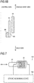
- Fig. 7 is a diagram illustrating the configuration of the stroke sensor system 101 provided in the shock absorber 1. As illustrated in Figs. 1 and 7 , the stroke sensor system 101 includes the cylinder 10, the coil 81, the collar 95, and the stroke measuring device 100. The collar 95 is omitted in Fig. 7 .
- the stroke measuring device 100 has a capacitor (not illustrated).
- the capacitor is electrically connected to the coil 81 to constitute an LC oscillation circuit together with the coil 81.
- the resonance frequency of the LC oscillation circuit changes according to the change in the stroke amount of the shock absorber 1.
- the stroke measuring device 100 outputs a stroke amount by performing predetermined processing on the oscillation signal output from the LC oscillation circuit.
- known processing disclosed in Patent Literature 1 and the like can be applied.
- the fitting length at which the cylinder 10, which is a conductor, and the coil 81 are fitted varies according to the stroke amount of the shock absorber 1.
- the fitting length becomes shorter, and when the shock absorber 1 contracts, the fitting length becomes longer.
- Fig. 8 is a graph illustrating the relationship between the fitting ratio and the sensor value and the relationship between the fitting ratio and the sensor gain in the stroke sensor system 101 (indicated as an example in Fig. 8 ) and a stroke sensor system of a comparative example.
- the stroke sensor system of the comparative example has the same configuration as the stroke sensor system 101 except that the collar 95 is not provided.
- the fitting ratio is a ratio of the fitting length to the length of the coil 81 in the axial direction. Even when the shock absorber 1 is in the most extended state, the vehicle-body-side end portion of the coil 81 and the axle-side end portion of the cylinder 10 are fitted and the lower limit of the fitting ratio is 10%.
- the sensor gain is a value obtained by differentiating the sensor value with respect to the stroke length and is a value indicating how much the sensor value changes when the piston rod 20 moves relative to the cylinder 10 by a minute unit distance.
- the sensor gain is a value indicating how much the sensor value changes when the fitting ratio changes by a minute unit ratio.
- both the sensor value and the sensor gain (ds/dx) are small at the end of the stroke, that is, in a region where the fitting ratio is close to 100%.
- the sensor gain (ds/dx) is close to zero.
- the stroke sensor system 101 can increase the sensor gain at the end of the stroke.
- the shock absorber 1 includes the stroke sensor system 101.
- the stroke sensor system 101 includes the cylinder 10, the coil 81 which moves relative to the cylinder 10 and is fitted to the axle side of the cylinder 10, and the collar 95 arranged on the end position side of the coil 81 when the position of the axle-side end portion of the cylinder 10 in a state where the fitting ratio between the cylinder 10 and the coil 81 is maximized is set as the end position.
- the collar 95 is located on the opposite side to the cylinder 10 with the coil 81 interposed therebetween.
- the sensor gain at the end of the stroke can be increased.
- the collar 95 contains iron or cobalt. By arranging the collar 95 containing iron or cobalt on the end position side of the coil 81, the sensor gain can be increased.
- shock absorber 1 is disposed on the axle side of the piston rod 20 and further includes the cylindrical protector 80 which receives the axle side of the cylinder 10. Also, the coil 81 is disposed inside the protector 80.
- the shock absorber 1 further includes the suspension spring 50 arranged outside the cylinder 10 and the spring receiver 94 which receives the load of the suspension spring 50 on the axle side of the piston rod 20.
- the collar 95 is formed integrally with the spring receiver 94 or is disposed adjacent to the spring receiver 94.
- the spring receiver 94 is disposed at the stroke end position in the shock absorber 1.
- Fig. 9A is a side view of a collar 97 (ferromagnetic body) according to the embodiment and Fig. 9B is a side view of another collar 98 (ferromagnetic body) according to the embodiment.
- 9C is a side view illustrating a collar 97a which is a modification example of the collar 97 and Fig. 9D is a perspective view illustrating a collar 98a which is a modification example of the collar 98.
- the collars 97, 97a, and 98 all have a substantially cylindrical shape, but are represented by rectangles in Figs. 9A to 9C .
- the flange portion 95b is omitted.
- Both collars 97 and 98 have a cylindrical shape. Specifically, as illustrated in Fig. 9A , the collar 97 has an opening portion 951 on the side surface. Further, as illustrated in Fig. 9B , the collar 98 has a notch portion 952 on the side surface.
- the resistance value of the collars 97 and 98 with respect to the current is larger than the resistance value of the collar 95 with respect to the current.
- the shape and number of the opening portions 951 illustrated in Fig. 9A and the shape and number of the notch portions 952 illustrated in Fig. 9B are examples.
- the collars 97 and 98 may have different shapes and numbers of the opening portions 951 or the notch portions 952. Furthermore, one collar 97 or 98 may have both the opening portion 951 and the notch portion 952.
- opening portions 951 illustrated in Fig. 9A and the notch portions 952 illustrated in Fig. 9B are regularly provided so as to be aligned in the axial direction.
- the opening portions 951 and the notch portions 952 may be provided irregularly.
- the collar 97a having a continuous notch portion 953 may be realized by forming the opening portions 951 continuously from one end side to the other end side of the collar 97.
- the collar 98a may be realized by forming a notch portion 954 continuous from one end side to the other end side in the collar 98.
- the opening portion 951 and the notch portion 952 are partially formed on the side surfaces of the collar 97/98. That is, a part of a plurality of cross sections obtained by cutting the collars 97 and 98 along a plurality of planes perpendicular to the axial directions of the collars 97 and 98 are preferably annular.
- the stroke sensor system 101 is provided in the shock absorber 1.
- the stroke sensor system 101 may be provided in another device that needs to measure the stroke amount.
Landscapes
- Engineering & Computer Science (AREA)
- General Engineering & Computer Science (AREA)
- Mechanical Engineering (AREA)
- Physics & Mathematics (AREA)
- General Physics & Mathematics (AREA)
- Fluid-Damping Devices (AREA)
- Measurement Of Length, Angles, Or The Like Using Electric Or Magnetic Means (AREA)
Abstract
Description
- The present invention relates to a stroke sensor system and a shock absorber including the stroke sensor system.
-
PTL 1 and 2 disclose a stroke sensor system including a movement amount deriving unit which obtains a movement amount when a cylinder and a rod inserted into the cylinder move relatively. In the stroke sensor system, a protective member (guide) is provided to protect the rod and a coil for obtaining the movement amount is provided inside the protective member. -
- PTL 1:
JP-A-2016-165984 - PTL 2:
JP-A-2016-166845 - When a ratio of fitting of the coil and the cylinder, which is a conductor, is increased, a change (hereinafter sometimes referred to as "sensor gain") in a stroke sensor output value (sensor value) per unit fitting length becomes small, and thus there is a problem that the function as a stroke sensor deteriorates.
- An object of the invention is to realize a stroke sensor system or the like which can increase a sensor gain at the end of a stroke.
- According to an aspect of the invention, there is provided a stroke sensor system which includes a conductor, a coil which moves relative to the conductor and is fitted to one end side of the conductor, and a ferromagnetic body which is arranged on an end position side of the coil when a position of an end portion on one end side of the conductor in a state where a fitting ratio between the conductor and the coil is maximized is defined as the end position, where the ferromagnetic body is located on an opposite side to the conductor with the coil interposed therebetween.
- According to the stroke sensor system of the aspect of the invention, the sensor gain at the end of the stroke can be increased.
-
-
Fig. 1 is a cross-sectional view illustrating a configuration of a shock absorber according to a first embodiment. -
Fig. 2 is an enlarged cross-sectional view illustrating a part of the shock absorber. -
Fig. 3 is a diagram conceptually illustrating an arrangement of a collar. -
Fig. 4 is an exploded perspective view illustrating a configuration of an axle side of the shock absorber. -
Fig. 5 is an enlarged perspective view illustrating a part of the shock absorber. -
Fig. 6A is a cross-sectional view illustrating an example of a positional relationship between a cylinder and a collar with respect to a coil included in the shock absorber. -
Fig. 6B is a cross-sectional view illustrating another example of the positional relationship between the cylinder and the collar with respect to the coil included in the shock absorber. -
Fig. 7 is a diagram illustrating a configuration of a stroke sensor system connected to the shock absorber. -
Fig. 8 is a graph illustrating a relationship between a fitting ratio and a sensor value in the stroke sensor system and a relationship between the fitting ratio and an amount of change in a sensor value per unit stroke length. -
Fig. 9A is a side view of a collar having a plurality of opening portions on a side surface. -
Fig. 9B is a side view of a collar having a notch portion. -
Fig. 9C is a side view of a collar having an opening portion formed continuously from one end to the other end on a side surface. -
Fig. 9D is a perspective view of a collar having a notch portion extending from one end to the other end on a side surface. - In the conventional stroke sensor system, a sensor gain is small in a state (end of stroke) where a fitting ratio between a conductor and a coil is the highest. For this reason, it is difficult to obtain a stroke amount with high accuracy at the end of the stroke.
- The inventor of the present application has found that it is possible to increase the sensor gain by arranging a ferromagnetic body at or near a position where an axle-side end portion of a cylinder reaches at the end of the stroke. Therefore, the inventor of the present application has come up with the present embodiments. Details of the embodiments will be described below.
- A
shock absorber 1 is provided in a vehicle, for example, a motorcycle. Theshock absorber 1 is preferably used particularly for buffering an impact received from a road surface between a rear axle of a vehicle and the vehicle body. Further, in the shock absorber 1, an axle side (one end side) and a vehicle body side (the other end side) are fixed. In the following description, a direction from the axle side to the vehicle body side (or the opposite direction) is referred to as an axial direction and a direction of rotation about the axial direction is referred to as a circumferential direction. -
Fig. 1 is a cross-sectional view illustrating a configuration of theshock absorber 1 according to the embodiment. Theshock absorber 1 includes astroke sensor system 101 in which the stroke amount of theshock absorber 1 is measured by astroke measuring device 100. As illustrated inFig. 1 , theshock absorber 1 includes a cylinder 10 (conductor), a piston rod 20 (rod), arod guide 30, apiston 40, asuspension spring 50, anattachment member 60, anattachment member 70, a protector 80 (protective member), aspring receiving mechanism 90, and thestroke measuring device 100. - The
cylinder 10 is a cylindrical member extending in an axial direction of theshock absorber 1. Thecylinder 10 is made of a conductive material and functions as a conductor. In addition, thecylinder 10 is constituted by a double pipe of anouter cylinder 11 and aninner cylinder 12. The vehicle-body-side end portions of theouter cylinder 11 and theinner cylinder 12 are closed and fixed to theattachment member 60. Therod guide 30 is fixed to an opening portion of the axle-side end portion of theouter cylinder 11. A predetermined interval for oil to flow in is provided between theouter cylinder 11 and theinner cylinder 12. - The
piston rod 20 is a rod-shaped member extending in the axial direction of theshock absorber 1 and is inserted into thecylinder 10 together withpiston 40, and further axially moved in thecylinder 10. Thepiston rod 20 is connected with thepiston 40 at the end portion on the vehicle body side and with theattachment member 70 at the end portion on the axle side. - The
rod guide 30 is a member which makes thepiston rod 20 penetrate therethrough and supports thepiston rod 20 and is fluid-tightly fixed to the inner periphery of the axle-side end portion of theouter cylinder 11 of thecylinder 10. Abump rubber 71 is disposed around the axle-side end portion of thepiston rod 20. Thebump rubber 71 absorbs the shock when an axle-side end surface of therod guide 30 comes into contact with theattachment member 70 when theshock absorber 1 is most compressed in the compression stroke. - The
piston 40 partitions the inside of theinner cylinder 12 into anoil chamber 12a and anoil chamber 12b and slides on the inner surface of theinner cylinder 12. In addition, around thepiston rod 20 between thepiston 40 and therod guide 30, there is provided arebound spring 41 which regulates the expansion side stroke of theshock absorber 1. - The
suspension spring 50 absorbs vibration that the rear wheel of the vehicle receives due to the unevenness of the road surface by expanding and contracting. Thesuspension spring 50 is disposed outside thecylinder 10 and theprotector 80. The axial position of thesuspension spring 50 is determined by being supported by thespring receiving mechanism 90 described below. - The
attachment member 60 is a member for attaching the shock absorber 1 to the vehicle body and is coupled to thecylinder 10 so as to cover the outer periphery of the vehicle-body-side end portion of theouter cylinder 11. Theattachment member 60 is formed of a nonferrous metal (nonmagnetic material) such as aluminum. - The
attachment member 70 is a member for attaching the shock absorber 1 to the axle and supports the axle-side end portion of theprotector 80. In addition, a female screw is formed at a vehicle-body-side end portion of theattachment member 70. This female screw is screwed with a male screw provided at the axle-side end portion of thepiston rod 20. - The
spring receiving mechanism 90 has aspring receiving portion 91 provided on the vehicle body side and aspring receiving portion 92 provided on the axle side. Thespring receiving portion 91 is fixed to the vehicle body side of thecylinder 10 so as to receive the load of thesuspension spring 50 on the vehicle body side. Thespring receiving portion 92 is fixed to the axle side of theshock absorber 1 so as to receive the load of thesuspension spring 50 on the axle side. - The
protector 80 is a member which is made of, for example, a resin and has a cylindrical shape extending in the axial direction of theshock absorber 1. Theprotector 80 is provided so as to cover an exposed part of thepiston rod 20 in order to protect thepiston rod 20 from flying pebbles and the like. Inside theprotector 80, acoil 81 is provided from the vehicle-body-side end portion of theprotector 80 to the axle-side end portion. Thecoil 81 is provided for measuring the stroke amount (relative position between thecylinder 10 and the protector 80). As theshock absorber 1 is compressed and expanded, theprotector 80 moves relative to thecylinder 10 and fits with one end side of thecylinder 10. - The
protector 80 has an inner diameter larger than the outer diameter of theouter cylinder 11 of thecylinder 10 so as to receive at least a part of thecylinder 10 from the vehicle body side to the inner portion. When theprotector 80 and theouter cylinder 11 move relative to each other, the axial length (fitting length) in which theprotector 80 and theouter cylinder 11 are fitted changes. By measuring the fitting length with thestroke measuring device 100, the stroke amount of theshock absorber 1 can be measured. -
Fig. 2 is an enlarged cross-sectional view illustrating a part of theshock absorber 1. As illustrated inFig. 2 , aflange portion 80a and aterminal portion 80b are provided at the axle-side end portion of theprotector 80. Theflange portion 80a is formed to extend in the radial direction of theprotector 80 and in the direction away from thepiston rod 20. An annular O-ring 96 having elasticity is disposed between the outer peripheral surface of theflange portion 80a and the inner peripheral surface of thecollar 95 and urges theprotector 80 toward a side on which thepiston rod 20 is located. - In the
terminal portion 80b, an end portion of asignal line 82 which electrically connects thecoil 81 and thestroke measuring device 100 is disposed. Further, in theterminal portion 80b, both ends of thecoil 81 and thesignal line 82 are electrically connected. - The
spring receiving portion 92 includes asheet stopper 93, aspring receiver 94, a collar 95 (ferromagnetic body), and the O-ring 96. - The
spring receiver 94 is an annular member provided to receive the spring load of thesuspension spring 50 on the axle side and is disposed in the vicinity of the axle-side end portion of theprotector 80. - The
collar 95 is a cylindrical member disposed on the axle side of theprotector 80. In the embodiment, thecollar 95 contains iron. In addition, thecollar 95 may contain cobalt.Fig. 3 is a diagram conceptually illustrating the arrangement of thecollar 95. InFig. 3 , members other than thecylinder 10, thecoil 81, and thecollar 95 are omitted. As illustrated inFig. 3 , anend position 21 is a position of an axle-side end portion 10a of thecylinder 10 in a state where the fitting ratio between thecylinder 10 and thecoil 81 is maximized. In other words, theend position 21 is the position of theend portion 10a when theshock absorber 1 is most compressed. An axle-side end portion 81a of thecoil 81 and an axle-side end portion 95a of thecollar 95 are located further on the axle side than theend position 21. That is, thecollar 95 is arranged on theend portion 81a side closer to theend position 21 among both ends of thecoil 81. InFig. 3 , for convenience, the positions of theend portion 81a and theend portion 95a are denoted byreference numerals 22 as being the same. - Since the
end portion 95a is positioned closer to the axle side than theend position 21, thecollar 95 can surround theend portion 10a at theend position 21 from the outside of thecoil 81. - The
end portion 95a may be arranged at the same position as theend position 21 in the axial direction of theshock absorber 1. Also, in the example illustrated inFig. 3 , the length of thecollar 95 is shorter than that of thecoil 81, but the length of thecollar 95 may be the same as that of thecoil 81. However, in order to reduce the weight of theshock absorber 1, it is preferable not to make thecollar 95 longer than necessary. - The
collar 95 has an inner diameter that is larger than the outer diameter of theprotector 80. The length of thecollar 95 in the axial direction is preferably 15% or more with respect to the length of thecoil 81. In the embodiment, thecollar 95 is disposed at a position adjacent to thespring receiver 94. However, thecollar 95 may be formed integrally with thespring receiver 94. Further, thecollar 95 may be a thin sheet-shaped member and may be attached to theprotector 80 using an adhesive. - As illustrated in
Fig. 2 , aflange portion 95b is provided at theend portion 95a of thecollar 95. Theflange portion 95b is formed so as to extend in the radial direction of thecollar 95 and in the direction away from thepiston rod 20. Theflange portion 95b is locked to astep portion 94b of thespring receiver 94. - The
step portion 94b is a portion which is recessed radially outward from the inner peripheral surface of the vehicle-body-side end portion of thespring receiver 94 and is formed over the entire inner periphery of thespring receiver 94. Thestep portion 94b prevents thecollar 95 from moving toward the vehicle body side. Therefore, the relative position between thecoil 81 and thecollar 95 is fixed. -
Fig. 4 is an exploded perspective view illustrating the configuration of the axle side of theshock absorber 1. As illustrated inFig. 4 , thesheet stopper 93 is a flat and annular member and has an outer diameter larger than the outer diameter of theflange portion 80a of theprotector 80. Thesheet stopper 93 is fixed by being fitted to the vehicle-body-side end portion of theattachment member 70 on the inner peripheral end surface. Thesheet stopper 93 is disposed so as to block a part of the axle-side opening portion of theprotector 80 in a state of being fixed to theattachment member 70. -
Fig. 5 is an enlarged perspective view illustrating a part of theshock absorber 1. As illustrated inFig. 5 , thesheet stopper 93 has a C-shape by having onenotch portion 93a. Thenotch portion 93a is formed so as to correspond to the shape of theterminal portion 80b of theprotector 80. By inserting theterminal portion 80b into thenotch portion 93a, the movement of theprotector 80 in the circumferential direction is suppressed. Further, thesheet stopper 93 has aprotrusion portion 93b which restricts the rotation of thesheet stopper 93 relative to thespring receiver 94 at the outer peripheral edge. - The
spring receiver 94 is provided with a plurality of extendingwalls 94a extending from the outer peripheral surface of thespring receiver 94 to the axle side. Theterminal portion 80b is disposed between two adjacent extendingwalls 94a and theprotrusion portion 93b is disposed between the other two adjacent extendingwalls 94a. -
Fig. 6A is a cross-sectional view illustrating an example of the positional relationship between thecylinder 10 and thecollar 95 with respect to thecoil 81.Fig. 6B is a cross-sectional view illustrating another example of the positional relationship. InFigs. 6A and6B , the common central axis of thecylinder 10, thecoil 81, and thecollar 95 is indicated by a one-dot chain line. - In the embodiment, as illustrated in
Fig. 6A , thecylinder 10 is located on the inside (side closer to the central axis) with respect to thecoil 81 and thecollar 95 is located on the outside (side far from the central axis) with respect to thecoil 81. However, as illustrated inFig. 6B , thecylinder 10 may be located outside thecoil 81. When thecylinder 10 is located on the outside with respect to thecoil 81, thecollar 95 is located on the inside with respect to thecoil 81. As described above, thecollar 95 may be located on the opposite side to thecylinder 10 with thecoil 81 interposed therebetween. - As illustrated in
Fig. 1 , thecoil 81 of theshock absorber 1 is connected to thestroke measuring device 100 via thesignal line 82. Thestroke measuring device 100 is realized by, for example, a control device provided in a vehicle. -
Fig. 7 is a diagram illustrating the configuration of thestroke sensor system 101 provided in theshock absorber 1. As illustrated inFigs. 1 and7 , thestroke sensor system 101 includes thecylinder 10, thecoil 81, thecollar 95, and thestroke measuring device 100. Thecollar 95 is omitted inFig. 7 . - The
stroke measuring device 100 has a capacitor (not illustrated). The capacitor is electrically connected to thecoil 81 to constitute an LC oscillation circuit together with thecoil 81. The resonance frequency of the LC oscillation circuit changes according to the change in the stroke amount of theshock absorber 1. - The
stroke measuring device 100 outputs a stroke amount by performing predetermined processing on the oscillation signal output from the LC oscillation circuit. For the above processing, known processing disclosed inPatent Literature 1 and the like can be applied. - In the
stroke sensor system 101, the fitting length at which thecylinder 10, which is a conductor, and thecoil 81 are fitted varies according to the stroke amount of theshock absorber 1. When theshock absorber 1 extends, the fitting length becomes shorter, and when theshock absorber 1 contracts, the fitting length becomes longer. - When an alternating current is made to flow to the
coil 81 when the fitting length changes, an eddy current is generated in thecylinder 10 so as to cancel the fluctuation of the magnetic field. Due to the action of eddy current, the magnetic field aroundcoil 81 is reduced. That is, the inductance of thecoil 81 is apparently reduced by the eddy current. When the fitting length is short (when theshock absorber 1 is extended), the influence of the eddy current is small, so that the inductance becomes larger. On the other hand, when the fitting length is long (when theshock absorber 1 is contracted), the influence of the eddy current is large, so that the inductance becomes smaller. - A resonance frequency f0 of the LC oscillation circuit is expressed as f0 = 1/(2π√(LC)), where L is the inductance of the
coil 81 and C is the capacitance of the capacitor. As a result, when the inductance L is large, the resonance frequency f0 becomes small, whereas when the inductance L is small, the resonance frequency f0 becomes large. Therefore, the stroke amount of theshock absorber 1 can be obtained from the resonance frequency. -
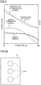
Fig. 8 is a graph illustrating the relationship between the fitting ratio and the sensor value and the relationship between the fitting ratio and the sensor gain in the stroke sensor system 101 (indicated as an example inFig. 8 ) and a stroke sensor system of a comparative example. The stroke sensor system of the comparative example has the same configuration as thestroke sensor system 101 except that thecollar 95 is not provided. - The fitting ratio is a ratio of the fitting length to the length of the
coil 81 in the axial direction. Even when theshock absorber 1 is in the most extended state, the vehicle-body-side end portion of thecoil 81 and the axle-side end portion of thecylinder 10 are fitted and the lower limit of the fitting ratio is 10%. - The sensor gain is a value obtained by differentiating the sensor value with respect to the stroke length and is a value indicating how much the sensor value changes when the
piston rod 20 moves relative to thecylinder 10 by a minute unit distance. In other words, the sensor gain is a value indicating how much the sensor value changes when the fitting ratio changes by a minute unit ratio. When s is set as the sensor value and x is set as the stroke length, the sensor gain can be expressed by ds/dx. - As illustrated in
Fig. 8 , in both the stroke sensor system 101 (example) and the stroke sensor system of the comparative example, both the sensor value and the sensor gain (ds/dx) are small at the end of the stroke, that is, in a region where the fitting ratio is close to 100%. In particular, in the comparative example, the sensor gain (ds/dx) is close to zero. - On the other hand, in a case of the
stroke sensor system 101, the sensor gain (ds/dx) at the end of the stroke is sufficiently larger than the value in the comparative example. Therefore, thestroke sensor system 101 can increase the sensor gain at the end of the stroke. - As described above, the
shock absorber 1 includes thestroke sensor system 101. Thestroke sensor system 101 includes thecylinder 10, thecoil 81 which moves relative to thecylinder 10 and is fitted to the axle side of thecylinder 10, and thecollar 95 arranged on the end position side of thecoil 81 when the position of the axle-side end portion of thecylinder 10 in a state where the fitting ratio between thecylinder 10 and thecoil 81 is maximized is set as the end position. Thecollar 95 is located on the opposite side to thecylinder 10 with thecoil 81 interposed therebetween. - With the configuration described above, the sensor gain at the end of the stroke can be increased.
- In the
stroke sensor system 101, thecollar 95 contains iron or cobalt. By arranging thecollar 95 containing iron or cobalt on the end position side of thecoil 81, the sensor gain can be increased. - Further, the
shock absorber 1 is disposed on the axle side of thepiston rod 20 and further includes thecylindrical protector 80 which receives the axle side of thecylinder 10. Also, thecoil 81 is disposed inside theprotector 80. - According to the configuration described above, by providing the
coil 81 inside theprotector 80 which protects thepiston rod 20, there is no need to additionally provide a member for arranging thecoil 81, and thus the configuration of theshock absorber 1 can be simplified. - The
shock absorber 1 further includes thesuspension spring 50 arranged outside thecylinder 10 and thespring receiver 94 which receives the load of thesuspension spring 50 on the axle side of thepiston rod 20. Thecollar 95 is formed integrally with thespring receiver 94 or is disposed adjacent to thespring receiver 94. Thespring receiver 94 is disposed at the stroke end position in theshock absorber 1. - By forming the
collar 95 integrally with thespring receiver 94 or by arranging thecollar 95 at the position adjacent to thespring receiver 94, while satisfying the condition that thecollar 95 is arranged at the end position of the stroke, it is possible to realize a rational structure in consideration of the positional relationship with other members. - Another embodiment of the invention will be described below.
-
Fig. 9A is a side view of a collar 97 (ferromagnetic body) according to the embodiment andFig. 9B is a side view of another collar 98 (ferromagnetic body) according to the embodiment. 9C is a side view illustrating acollar 97a which is a modification example of thecollar 97 andFig. 9D is a perspective view illustrating acollar 98a which is a modification example of thecollar 98. Thecollars Figs. 9A to 9C . In addition, inFigs. 9A to 9D , theflange portion 95b is omitted. - Both
collars Fig. 9A , thecollar 97 has anopening portion 951 on the side surface. Further, as illustrated inFig. 9B , thecollar 98 has anotch portion 952 on the side surface. - Therefore, in the
collars opening portion 951 or thenotch portion 952. In other words, the resistance value of thecollars collar 95 with respect to the current. - When the eddy current flowing through the
collar 95 is increased, there is a possibility that the sensitivity of thestroke sensor system 101 is decreased. By using thecollar collar 95, the eddy current flowing through thecollars stroke sensor system 101 can be increased. - The shape and number of the opening
portions 951 illustrated inFig. 9A and the shape and number of thenotch portions 952 illustrated inFig. 9B are examples. Thecollars portions 951 or thenotch portions 952. Furthermore, onecollar opening portion 951 and thenotch portion 952. - Further, the opening
portions 951 illustrated inFig. 9A and thenotch portions 952 illustrated inFig. 9B are regularly provided so as to be aligned in the axial direction. However, the openingportions 951 and thenotch portions 952 may be provided irregularly. - Furthermore, as illustrated in
Fig. 9C , thecollar 97a having acontinuous notch portion 953 may be realized by forming the openingportions 951 continuously from one end side to the other end side of thecollar 97. Similarly, as illustrated inFig. 9D , thecollar 98a may be realized by forming anotch portion 954 continuous from one end side to the other end side in thecollar 98. By forming thenotch portion 953/954 continuous from one end side to the other end in this manner, the eddy current flowing through thecollar 97a/98a can be more effectively suppressed than in a case of thecollar 97/98. - Further, from the viewpoint of maintaining the shape of the collar, it is preferable that the
opening portion 951 and thenotch portion 952 are partially formed on the side surfaces of thecollar 97/98. That is, a part of a plurality of cross sections obtained by cutting thecollars collars - In the embodiment described above, the configuration in which the
cylinder 10 is arranged on the vehicle body side and theprotector 80 is arranged on the axle side has been described, but the arrangement relationship between thecylinder 10 and theprotector 80 may be reversed. - In the embodiment described above, the
stroke sensor system 101 is provided in theshock absorber 1. However, thestroke sensor system 101 may be provided in another device that needs to measure the stroke amount. - The invention is not limited to the embodiments described above and various modifications are possible within the scope of the claims. Embodiments obtained by appropriately combining technical means disclosed in different embodiments are also included in the technical scope of the invention.
-
- 1
- shock absorber
- 10
- cylinder (conductor)
- 10a
- end portion
- 20
- piston rod (rod)
- 21
- end position
- 50
- suspension spring
- 80
- protector (protective member)
- 81
- coil
- 94
- spring receiver
- 95, 97, 98
- collar (ferromagnetic body)
- 951
- opening portion
- 952
- notch portion
- 953
- notch portion
- 954
- notch portion
- 101
- stroke sensor system
Claims (7)
- A stroke sensor system, comprising:a conductor;a coil which moves relative to the conductor and is fitted to one end side of the conductor; anda ferromagnetic body which is arranged on an end position side of the coil, wherein a position of an end portion on one end side of the conductor in a state where a fitting ratio between the conductor and the coil is maximized is defined as the end position, whereinthe ferromagnetic body is located on an opposite side to the conductor with the coil interposed therebetween.
- The stroke sensor system according to claim 1, wherein
the ferromagnetic body has a cylindrical shape and has an opening portion or a notch portion on a side surface of the ferromagnetic body. - The stroke sensor system according to claim 1, wherein
the ferromagnetic body partially has a cylindrical shape and has a notch portion continuous from one end side to the other end side of the ferromagnetic body. - The stroke sensor system according to any one of claims 1 to 3, wherein
the ferromagnetic body contains iron or cobalt. - A shock absorber which includes the stroke sensor system according to any one of claims 1 to 4, comprising:a cylinder configured to be the conductor;a rod inserted into the cylinder from one end side of the cylinder;the coil disposed on one end side of the rod; andthe ferromagnetic body disposed on one end side of the coil.
- The shock absorber according to claim 5, further comprising:a protective member having a cylindrical shape which is disposed on the one end side of the rod and receives one end side of the cylinder, whereinthe coil is disposed inside the protective member.
- The shock absorber according to claim 5 or 6, further comprising:a suspension spring disposed outside the cylinder; anda spring receiver which receives a load of the suspension spring on the one end side of the rod, whereinthe ferromagnetic body is formed integrally with the spring receiver or is disposed at a position adjacent to the spring receiver.
Applications Claiming Priority (2)
| Application Number | Priority Date | Filing Date | Title |
|---|---|---|---|
| JP2017201851A JP6338757B1 (en) | 2017-10-18 | 2017-10-18 | Stroke sensor system and shock absorber |
| PCT/JP2017/038972 WO2019077759A1 (en) | 2017-10-18 | 2017-10-27 | Stroke sensor system and shock absorber |
Publications (3)
| Publication Number | Publication Date |
|---|---|
| EP3699451A1 true EP3699451A1 (en) | 2020-08-26 |
| EP3699451A4 EP3699451A4 (en) | 2021-07-07 |
| EP3699451B1 EP3699451B1 (en) | 2022-10-12 |
Family
ID=62487352
Family Applications (1)
| Application Number | Title | Priority Date | Filing Date |
|---|---|---|---|
| EP17929029.1A Active EP3699451B1 (en) | 2017-10-18 | 2017-10-27 | Stroke sensor system and shock absorber |
Country Status (4)
| Country | Link |
|---|---|
| US (1) | US11313428B2 (en) |
| EP (1) | EP3699451B1 (en) |
| JP (1) | JP6338757B1 (en) |
| WO (1) | WO2019077759A1 (en) |
Families Citing this family (5)
| Publication number | Priority date | Publication date | Assignee | Title |
|---|---|---|---|---|
| WO2021019764A1 (en) | 2019-08-01 | 2021-02-04 | 株式会社ショ-ワ | Suspension device and front fork |
| JP7233394B2 (en) * | 2020-03-24 | 2023-03-06 | 日立Astemo株式会社 | hydraulic buffer |
| JP2022083556A (en) * | 2020-11-25 | 2022-06-06 | 日立Astemo株式会社 | Damper |
| JP2024002002A (en) * | 2022-06-23 | 2024-01-11 | カヤバ株式会社 | stroke sensor |
| WO2026009338A1 (en) * | 2024-07-03 | 2026-01-08 | Astemo株式会社 | Shock absorber |
Family Cites Families (11)
| Publication number | Priority date | Publication date | Assignee | Title |
|---|---|---|---|---|
| DE3528341C1 (en) * | 1985-08-07 | 1986-05-22 | F & O Electronic Systems GmbH & Co, 6901 Neckarsteinach | Adjustable valve for the piston rod of a vibration damper |
| DE3832625C2 (en) * | 1987-10-13 | 1999-06-24 | Hauni Werke Koerber & Co Kg | Vibration damper with variable damping characteristics |
| FR2701525B1 (en) * | 1993-02-12 | 1995-04-21 | Hutchinson | Improvements to hydraulic anti-vibration devices. |
| DE9404164U1 (en) * | 1993-05-27 | 1994-05-19 | Fa. Hermann Heye, 31683 Obernkirchen | Position transducer for verifying the position of a press ram |
| JP2003347124A (en) * | 2002-05-27 | 2003-12-05 | Matsushita Electric Ind Co Ltd | Magnetic element and power module using the same |
| JP2007242635A (en) * | 2007-06-11 | 2007-09-20 | Ricoh Co Ltd | Heating apparatus and image forming apparatus |
| US8307700B2 (en) * | 2010-02-19 | 2012-11-13 | Sunpower, Inc. | Internal position and limit sensor for free piston machines |
| AU2015236298B2 (en) | 2014-03-24 | 2018-08-09 | Apple Inc. | Magnetic shielding in inductive power transfer |
| JP6450611B2 (en) * | 2015-03-10 | 2019-01-09 | 株式会社ショーワ | Stroke sensor system |
| JP6294846B2 (en) | 2015-03-10 | 2018-03-14 | 株式会社ショーワ | Stroke sensor system |
| JP6417257B2 (en) * | 2015-03-31 | 2018-11-07 | 株式会社ショーワ | Front fork |
-
2017
- 2017-10-18 JP JP2017201851A patent/JP6338757B1/en active Active
- 2017-10-27 EP EP17929029.1A patent/EP3699451B1/en active Active
- 2017-10-27 WO PCT/JP2017/038972 patent/WO2019077759A1/en not_active Ceased
-
2020
- 2020-02-24 US US16/799,289 patent/US11313428B2/en active Active
Also Published As
| Publication number | Publication date |
|---|---|
| US20200191228A1 (en) | 2020-06-18 |
| EP3699451B1 (en) | 2022-10-12 |
| WO2019077759A1 (en) | 2019-04-25 |
| US11313428B2 (en) | 2022-04-26 |
| EP3699451A4 (en) | 2021-07-07 |
| JP2019074463A (en) | 2019-05-16 |
| JP6338757B1 (en) | 2018-06-06 |
Similar Documents
| Publication | Publication Date | Title |
|---|---|---|
| US11313428B2 (en) | Stroke sensor system and shock absorber | |
| EP3009706B1 (en) | Air spring hybrid piston assembly | |
| US9352630B2 (en) | Jounce bumpers and spring assemblies including same | |
| US4949573A (en) | Velocity transducer for vehicle suspension system | |
| US7188827B2 (en) | Gas spring with a protective sleeve for a rolling bellows | |
| US11215258B2 (en) | Hydraulic shock absorber | |
| EP3177849B1 (en) | Performance-variable bushings as well as gas spring and damper assemblies including same | |
| US6866127B2 (en) | Piston damper assembly, and dust tube subassembly, having a velocity sensor | |
| US11391338B2 (en) | Shock absorber | |
| US10464385B2 (en) | Jounce bumpers and spring assemblies including same | |
| US20180031070A1 (en) | Shock absorber | |
| US20200262260A1 (en) | Damper mount | |
| CN106515345B (en) | Air spring device for vehicle | |
| CN206400118U (en) | A kind of wireless proximity transducer | |
| CN113218486A (en) | Telescopic vibration damper for motor vehicle | |
| JP5193123B2 (en) | Damper device | |
| JPH07259907A (en) | Coil compression spring device | |
| EP3279499B1 (en) | Hydraulic damper having self-adjusting wear band | |
| US7543687B2 (en) | Piston damper assembly, and dust tube subassembly, having a position sensor | |
| JP6511338B2 (en) | Air spring | |
| RU106587U1 (en) | DEVICE FOR MOUNTING SHOCK ABSORBER FOR CAR SUSPENSION (OPTIONS) | |
| EP3248817A1 (en) | Jounce bumpers and spring assemblies including same | |
| TH136608A (en) |
Legal Events
| Date | Code | Title | Description |
|---|---|---|---|
| STAA | Information on the status of an ep patent application or granted ep patent |
Free format text: STATUS: THE INTERNATIONAL PUBLICATION HAS BEEN MADE |
|
| PUAI | Public reference made under article 153(3) epc to a published international application that has entered the european phase |
Free format text: ORIGINAL CODE: 0009012 |
|
| STAA | Information on the status of an ep patent application or granted ep patent |
Free format text: STATUS: REQUEST FOR EXAMINATION WAS MADE |
|
| 17P | Request for examination filed |
Effective date: 20200225 |
|
| AK | Designated contracting states |
Kind code of ref document: A1 Designated state(s): AL AT BE BG CH CY CZ DE DK EE ES FI FR GB GR HR HU IE IS IT LI LT LU LV MC MK MT NL NO PL PT RO RS SE SI SK SM TR |
|
| AX | Request for extension of the european patent |
Extension state: BA ME |
|
| DAV | Request for validation of the european patent (deleted) | ||
| DAX | Request for extension of the european patent (deleted) | ||
| A4 | Supplementary search report drawn up and despatched |
Effective date: 20210607 |
|
| RIC1 | Information provided on ipc code assigned before grant |
Ipc: F16F 9/32 20060101AFI20210531BHEP Ipc: F16F 9/38 20060101ALI20210531BHEP Ipc: B60G 15/06 20060101ALI20210531BHEP Ipc: B60G 13/08 20060101ALI20210531BHEP Ipc: B62K 25/04 20060101ALI20210531BHEP Ipc: G01B 7/00 20060101ALI20210531BHEP Ipc: G01D 5/20 20060101ALI20210531BHEP Ipc: F16F 1/12 20060101ALN20210531BHEP Ipc: F16F 9/18 20060101ALN20210531BHEP Ipc: F16F 13/00 20060101ALN20210531BHEP |
|
| RAP1 | Party data changed (applicant data changed or rights of an application transferred) |
Owner name: HITACHI AUTOMOTIVE SYSTEMS, LTD. |
|
| GRAP | Despatch of communication of intention to grant a patent |
Free format text: ORIGINAL CODE: EPIDOSNIGR1 |
|
| STAA | Information on the status of an ep patent application or granted ep patent |
Free format text: STATUS: GRANT OF PATENT IS INTENDED |
|
| RAP1 | Party data changed (applicant data changed or rights of an application transferred) |
Owner name: HITACHI ASTEMO, LTD. |
|
| RIC1 | Information provided on ipc code assigned before grant |
Ipc: F16F 13/00 20060101ALN20220502BHEP Ipc: F16F 9/18 20060101ALN20220502BHEP Ipc: F16F 1/12 20060101ALN20220502BHEP Ipc: G01D 5/20 20060101ALI20220502BHEP Ipc: G01B 7/00 20060101ALI20220502BHEP Ipc: B62K 25/04 20060101ALI20220502BHEP Ipc: B60G 13/08 20060101ALI20220502BHEP Ipc: B60G 15/06 20060101ALI20220502BHEP Ipc: F16F 9/38 20060101ALI20220502BHEP Ipc: F16F 9/32 20060101AFI20220502BHEP |
|
| RIC1 | Information provided on ipc code assigned before grant |
Ipc: F16F 13/00 20060101ALN20220509BHEP Ipc: F16F 9/18 20060101ALN20220509BHEP Ipc: F16F 1/12 20060101ALN20220509BHEP Ipc: G01D 5/20 20060101ALI20220509BHEP Ipc: G01B 7/00 20060101ALI20220509BHEP Ipc: B62K 25/04 20060101ALI20220509BHEP Ipc: B60G 13/08 20060101ALI20220509BHEP Ipc: B60G 15/06 20060101ALI20220509BHEP Ipc: F16F 9/38 20060101ALI20220509BHEP Ipc: F16F 9/32 20060101AFI20220509BHEP |
|
| INTG | Intention to grant announced |
Effective date: 20220524 |
|
| GRAS | Grant fee paid |
Free format text: ORIGINAL CODE: EPIDOSNIGR3 |
|
| GRAA | (expected) grant |
Free format text: ORIGINAL CODE: 0009210 |
|
| STAA | Information on the status of an ep patent application or granted ep patent |
Free format text: STATUS: THE PATENT HAS BEEN GRANTED |
|
| AK | Designated contracting states |
Kind code of ref document: B1 Designated state(s): AL AT BE BG CH CY CZ DE DK EE ES FI FR GB GR HR HU IE IS IT LI LT LU LV MC MK MT NL NO PL PT RO RS SE SI SK SM TR |
|
| REG | Reference to a national code |
Ref country code: GB Ref legal event code: FG4D |
|
| REG | Reference to a national code |
Ref country code: CH Ref legal event code: EP |
|
| REG | Reference to a national code |
Ref country code: DE Ref legal event code: R096 Ref document number: 602017062698 Country of ref document: DE |
|
| REG | Reference to a national code |
Ref country code: IE Ref legal event code: FG4D |
|
| REG | Reference to a national code |
Ref country code: AT Ref legal event code: REF Ref document number: 1524350 Country of ref document: AT Kind code of ref document: T Effective date: 20221115 |
|
| REG | Reference to a national code |
Ref country code: LT Ref legal event code: MG9D |
|
| REG | Reference to a national code |
Ref country code: NL Ref legal event code: MP Effective date: 20221012 |
|
| REG | Reference to a national code |
Ref country code: AT Ref legal event code: MK05 Ref document number: 1524350 Country of ref document: AT Kind code of ref document: T Effective date: 20221012 |
|
| PG25 | Lapsed in a contracting state [announced via postgrant information from national office to epo] |
Ref country code: NL Free format text: LAPSE BECAUSE OF FAILURE TO SUBMIT A TRANSLATION OF THE DESCRIPTION OR TO PAY THE FEE WITHIN THE PRESCRIBED TIME-LIMIT Effective date: 20221012 |
|
| PG25 | Lapsed in a contracting state [announced via postgrant information from national office to epo] |
Ref country code: SE Free format text: LAPSE BECAUSE OF FAILURE TO SUBMIT A TRANSLATION OF THE DESCRIPTION OR TO PAY THE FEE WITHIN THE PRESCRIBED TIME-LIMIT Effective date: 20221012 Ref country code: PT Free format text: LAPSE BECAUSE OF FAILURE TO SUBMIT A TRANSLATION OF THE DESCRIPTION OR TO PAY THE FEE WITHIN THE PRESCRIBED TIME-LIMIT Effective date: 20230213 Ref country code: NO Free format text: LAPSE BECAUSE OF FAILURE TO SUBMIT A TRANSLATION OF THE DESCRIPTION OR TO PAY THE FEE WITHIN THE PRESCRIBED TIME-LIMIT Effective date: 20230112 Ref country code: LT Free format text: LAPSE BECAUSE OF FAILURE TO SUBMIT A TRANSLATION OF THE DESCRIPTION OR TO PAY THE FEE WITHIN THE PRESCRIBED TIME-LIMIT Effective date: 20221012 Ref country code: FI Free format text: LAPSE BECAUSE OF FAILURE TO SUBMIT A TRANSLATION OF THE DESCRIPTION OR TO PAY THE FEE WITHIN THE PRESCRIBED TIME-LIMIT Effective date: 20221012 Ref country code: ES Free format text: LAPSE BECAUSE OF FAILURE TO SUBMIT A TRANSLATION OF THE DESCRIPTION OR TO PAY THE FEE WITHIN THE PRESCRIBED TIME-LIMIT Effective date: 20221012 Ref country code: AT Free format text: LAPSE BECAUSE OF FAILURE TO SUBMIT A TRANSLATION OF THE DESCRIPTION OR TO PAY THE FEE WITHIN THE PRESCRIBED TIME-LIMIT Effective date: 20221012 |
|
| PG25 | Lapsed in a contracting state [announced via postgrant information from national office to epo] |
Ref country code: RS Free format text: LAPSE BECAUSE OF FAILURE TO SUBMIT A TRANSLATION OF THE DESCRIPTION OR TO PAY THE FEE WITHIN THE PRESCRIBED TIME-LIMIT Effective date: 20221012 Ref country code: PL Free format text: LAPSE BECAUSE OF FAILURE TO SUBMIT A TRANSLATION OF THE DESCRIPTION OR TO PAY THE FEE WITHIN THE PRESCRIBED TIME-LIMIT Effective date: 20221012 Ref country code: LV Free format text: LAPSE BECAUSE OF FAILURE TO SUBMIT A TRANSLATION OF THE DESCRIPTION OR TO PAY THE FEE WITHIN THE PRESCRIBED TIME-LIMIT Effective date: 20221012 Ref country code: IS Free format text: LAPSE BECAUSE OF FAILURE TO SUBMIT A TRANSLATION OF THE DESCRIPTION OR TO PAY THE FEE WITHIN THE PRESCRIBED TIME-LIMIT Effective date: 20230212 Ref country code: HR Free format text: LAPSE BECAUSE OF FAILURE TO SUBMIT A TRANSLATION OF THE DESCRIPTION OR TO PAY THE FEE WITHIN THE PRESCRIBED TIME-LIMIT Effective date: 20221012 Ref country code: GR Free format text: LAPSE BECAUSE OF FAILURE TO SUBMIT A TRANSLATION OF THE DESCRIPTION OR TO PAY THE FEE WITHIN THE PRESCRIBED TIME-LIMIT Effective date: 20230113 |
|
| REG | Reference to a national code |
Ref country code: CH Ref legal event code: PL |
|
| REG | Reference to a national code |
Ref country code: BE Ref legal event code: MM Effective date: 20221031 |
|
| PG25 | Lapsed in a contracting state [announced via postgrant information from national office to epo] |
Ref country code: LU Free format text: LAPSE BECAUSE OF NON-PAYMENT OF DUE FEES Effective date: 20221027 |
|
| REG | Reference to a national code |
Ref country code: DE Ref legal event code: R097 Ref document number: 602017062698 Country of ref document: DE |
|
| PG25 | Lapsed in a contracting state [announced via postgrant information from national office to epo] |
Ref country code: SM Free format text: LAPSE BECAUSE OF FAILURE TO SUBMIT A TRANSLATION OF THE DESCRIPTION OR TO PAY THE FEE WITHIN THE PRESCRIBED TIME-LIMIT Effective date: 20221012 Ref country code: RO Free format text: LAPSE BECAUSE OF FAILURE TO SUBMIT A TRANSLATION OF THE DESCRIPTION OR TO PAY THE FEE WITHIN THE PRESCRIBED TIME-LIMIT Effective date: 20221012 Ref country code: MC Free format text: LAPSE BECAUSE OF FAILURE TO SUBMIT A TRANSLATION OF THE DESCRIPTION OR TO PAY THE FEE WITHIN THE PRESCRIBED TIME-LIMIT Effective date: 20221012 Ref country code: LI Free format text: LAPSE BECAUSE OF NON-PAYMENT OF DUE FEES Effective date: 20221031 Ref country code: EE Free format text: LAPSE BECAUSE OF FAILURE TO SUBMIT A TRANSLATION OF THE DESCRIPTION OR TO PAY THE FEE WITHIN THE PRESCRIBED TIME-LIMIT Effective date: 20221012 Ref country code: DK Free format text: LAPSE BECAUSE OF FAILURE TO SUBMIT A TRANSLATION OF THE DESCRIPTION OR TO PAY THE FEE WITHIN THE PRESCRIBED TIME-LIMIT Effective date: 20221012 Ref country code: CZ Free format text: LAPSE BECAUSE OF FAILURE TO SUBMIT A TRANSLATION OF THE DESCRIPTION OR TO PAY THE FEE WITHIN THE PRESCRIBED TIME-LIMIT Effective date: 20221012 Ref country code: CH Free format text: LAPSE BECAUSE OF NON-PAYMENT OF DUE FEES Effective date: 20221031 |
|
| PLBE | No opposition filed within time limit |
Free format text: ORIGINAL CODE: 0009261 |
|
| STAA | Information on the status of an ep patent application or granted ep patent |
Free format text: STATUS: NO OPPOSITION FILED WITHIN TIME LIMIT |
|
| PG25 | Lapsed in a contracting state [announced via postgrant information from national office to epo] |
Ref country code: SK Free format text: LAPSE BECAUSE OF FAILURE TO SUBMIT A TRANSLATION OF THE DESCRIPTION OR TO PAY THE FEE WITHIN THE PRESCRIBED TIME-LIMIT Effective date: 20221012 Ref country code: AL Free format text: LAPSE BECAUSE OF FAILURE TO SUBMIT A TRANSLATION OF THE DESCRIPTION OR TO PAY THE FEE WITHIN THE PRESCRIBED TIME-LIMIT Effective date: 20221012 |
|
| 26N | No opposition filed |
Effective date: 20230713 |
|
| PG25 | Lapsed in a contracting state [announced via postgrant information from national office to epo] |
Ref country code: BE Free format text: LAPSE BECAUSE OF NON-PAYMENT OF DUE FEES Effective date: 20221031 |
|
| PG25 | Lapsed in a contracting state [announced via postgrant information from national office to epo] |
Ref country code: IE Free format text: LAPSE BECAUSE OF NON-PAYMENT OF DUE FEES Effective date: 20221027 |
|
| PG25 | Lapsed in a contracting state [announced via postgrant information from national office to epo] |
Ref country code: SI Free format text: LAPSE BECAUSE OF FAILURE TO SUBMIT A TRANSLATION OF THE DESCRIPTION OR TO PAY THE FEE WITHIN THE PRESCRIBED TIME-LIMIT Effective date: 20221012 Ref country code: FR Free format text: LAPSE BECAUSE OF NON-PAYMENT OF DUE FEES Effective date: 20221212 |
|
| PG25 | Lapsed in a contracting state [announced via postgrant information from national office to epo] |
Ref country code: CY Free format text: LAPSE BECAUSE OF FAILURE TO SUBMIT A TRANSLATION OF THE DESCRIPTION OR TO PAY THE FEE WITHIN THE PRESCRIBED TIME-LIMIT Effective date: 20221012 |
|
| PG25 | Lapsed in a contracting state [announced via postgrant information from national office to epo] |
Ref country code: MK Free format text: LAPSE BECAUSE OF FAILURE TO SUBMIT A TRANSLATION OF THE DESCRIPTION OR TO PAY THE FEE WITHIN THE PRESCRIBED TIME-LIMIT Effective date: 20221012 Ref country code: HU Free format text: LAPSE BECAUSE OF FAILURE TO SUBMIT A TRANSLATION OF THE DESCRIPTION OR TO PAY THE FEE WITHIN THE PRESCRIBED TIME-LIMIT; INVALID AB INITIO Effective date: 20171027 |
|
| PG25 | Lapsed in a contracting state [announced via postgrant information from national office to epo] |
Ref country code: BG Free format text: LAPSE BECAUSE OF FAILURE TO SUBMIT A TRANSLATION OF THE DESCRIPTION OR TO PAY THE FEE WITHIN THE PRESCRIBED TIME-LIMIT Effective date: 20221012 |
|
| PG25 | Lapsed in a contracting state [announced via postgrant information from national office to epo] |
Ref country code: MT Free format text: LAPSE BECAUSE OF FAILURE TO SUBMIT A TRANSLATION OF THE DESCRIPTION OR TO PAY THE FEE WITHIN THE PRESCRIBED TIME-LIMIT Effective date: 20221012 |
|
| REG | Reference to a national code |
Ref country code: DE Ref legal event code: R082 Ref document number: 602017062698 Country of ref document: DE Representative=s name: MAUCHER JENKINS PATENTANWAELTE & RECHTSANWAELT, DE |
|
| PGFP | Annual fee paid to national office [announced via postgrant information from national office to epo] |
Ref country code: IT Payment date: 20250922 Year of fee payment: 9 |
|
| PGFP | Annual fee paid to national office [announced via postgrant information from national office to epo] |
Ref country code: GB Payment date: 20250904 Year of fee payment: 9 |
|
| PG25 | Lapsed in a contracting state [announced via postgrant information from national office to epo] |
Ref country code: TR Free format text: LAPSE BECAUSE OF FAILURE TO SUBMIT A TRANSLATION OF THE DESCRIPTION OR TO PAY THE FEE WITHIN THE PRESCRIBED TIME-LIMIT Effective date: 20221012 |
|
| PGFP | Annual fee paid to national office [announced via postgrant information from national office to epo] |
Ref country code: DE Payment date: 20250902 Year of fee payment: 9 |