EP3699053B1 - Method and apparatus for planning speed of autonomous vehicle, and storage medium - Google Patents
Method and apparatus for planning speed of autonomous vehicle, and storage medium Download PDFInfo
- Publication number
- EP3699053B1 EP3699053B1 EP20275038.6A EP20275038A EP3699053B1 EP 3699053 B1 EP3699053 B1 EP 3699053B1 EP 20275038 A EP20275038 A EP 20275038A EP 3699053 B1 EP3699053 B1 EP 3699053B1
- Authority
- EP
- European Patent Office
- Prior art keywords
- speed
- time point
- trajectory
- distance
- autonomous vehicle
- Prior art date
- Legal status (The legal status is an assumption and is not a legal conclusion. Google has not performed a legal analysis and makes no representation as to the accuracy of the status listed.)
- Active
Links
Images



Classifications
-
- B—PERFORMING OPERATIONS; TRANSPORTING
- B60—VEHICLES IN GENERAL
- B60W—CONJOINT CONTROL OF VEHICLE SUB-UNITS OF DIFFERENT TYPE OR DIFFERENT FUNCTION; CONTROL SYSTEMS SPECIALLY ADAPTED FOR HYBRID VEHICLES; ROAD VEHICLE DRIVE CONTROL SYSTEMS FOR PURPOSES NOT RELATED TO THE CONTROL OF A PARTICULAR SUB-UNIT
- B60W60/00—Drive control systems specially adapted for autonomous road vehicles
- B60W60/001—Planning or execution of driving tasks
- B60W60/0011—Planning or execution of driving tasks involving control alternatives for a single driving scenario, e.g. planning several paths to avoid obstacles
-
- B—PERFORMING OPERATIONS; TRANSPORTING
- B60—VEHICLES IN GENERAL
- B60W—CONJOINT CONTROL OF VEHICLE SUB-UNITS OF DIFFERENT TYPE OR DIFFERENT FUNCTION; CONTROL SYSTEMS SPECIALLY ADAPTED FOR HYBRID VEHICLES; ROAD VEHICLE DRIVE CONTROL SYSTEMS FOR PURPOSES NOT RELATED TO THE CONTROL OF A PARTICULAR SUB-UNIT
- B60W30/00—Purposes of road vehicle drive control systems not related to the control of a particular sub-unit, e.g. of systems using conjoint control of vehicle sub-units
- B60W30/10—Path keeping
-
- B—PERFORMING OPERATIONS; TRANSPORTING
- B60—VEHICLES IN GENERAL
- B60W—CONJOINT CONTROL OF VEHICLE SUB-UNITS OF DIFFERENT TYPE OR DIFFERENT FUNCTION; CONTROL SYSTEMS SPECIALLY ADAPTED FOR HYBRID VEHICLES; ROAD VEHICLE DRIVE CONTROL SYSTEMS FOR PURPOSES NOT RELATED TO THE CONTROL OF A PARTICULAR SUB-UNIT
- B60W30/00—Purposes of road vehicle drive control systems not related to the control of a particular sub-unit, e.g. of systems using conjoint control of vehicle sub-units
- B60W30/14—Adaptive cruise control
-
- B—PERFORMING OPERATIONS; TRANSPORTING
- B60—VEHICLES IN GENERAL
- B60W—CONJOINT CONTROL OF VEHICLE SUB-UNITS OF DIFFERENT TYPE OR DIFFERENT FUNCTION; CONTROL SYSTEMS SPECIALLY ADAPTED FOR HYBRID VEHICLES; ROAD VEHICLE DRIVE CONTROL SYSTEMS FOR PURPOSES NOT RELATED TO THE CONTROL OF A PARTICULAR SUB-UNIT
- B60W30/00—Purposes of road vehicle drive control systems not related to the control of a particular sub-unit, e.g. of systems using conjoint control of vehicle sub-units
- B60W30/18—Propelling the vehicle
- B60W30/18009—Propelling the vehicle related to particular drive situations
- B60W30/18163—Lane change; Overtaking manoeuvres
-
- B—PERFORMING OPERATIONS; TRANSPORTING
- B60—VEHICLES IN GENERAL
- B60W—CONJOINT CONTROL OF VEHICLE SUB-UNITS OF DIFFERENT TYPE OR DIFFERENT FUNCTION; CONTROL SYSTEMS SPECIALLY ADAPTED FOR HYBRID VEHICLES; ROAD VEHICLE DRIVE CONTROL SYSTEMS FOR PURPOSES NOT RELATED TO THE CONTROL OF A PARTICULAR SUB-UNIT
- B60W40/00—Estimation or calculation of non-directly measurable driving parameters for road vehicle drive control systems not related to the control of a particular sub unit, e.g. by using mathematical models
- B60W40/10—Estimation or calculation of non-directly measurable driving parameters for road vehicle drive control systems not related to the control of a particular sub unit, e.g. by using mathematical models related to vehicle motion
- B60W40/105—Speed
-
- B—PERFORMING OPERATIONS; TRANSPORTING
- B60—VEHICLES IN GENERAL
- B60W—CONJOINT CONTROL OF VEHICLE SUB-UNITS OF DIFFERENT TYPE OR DIFFERENT FUNCTION; CONTROL SYSTEMS SPECIALLY ADAPTED FOR HYBRID VEHICLES; ROAD VEHICLE DRIVE CONTROL SYSTEMS FOR PURPOSES NOT RELATED TO THE CONTROL OF A PARTICULAR SUB-UNIT
- B60W50/00—Details of control systems for road vehicle drive control not related to the control of a particular sub-unit, e.g. process diagnostic or vehicle driver interfaces
- B60W50/0097—Predicting future conditions
-
- G—PHYSICS
- G01—MEASURING; TESTING
- G01C—MEASURING DISTANCES, LEVELS OR BEARINGS; SURVEYING; NAVIGATION; GYROSCOPIC INSTRUMENTS; PHOTOGRAMMETRY OR VIDEOGRAMMETRY
- G01C21/00—Navigation; Navigational instruments not provided for in groups G01C1/00 - G01C19/00
- G01C21/26—Navigation; Navigational instruments not provided for in groups G01C1/00 - G01C19/00 specially adapted for navigation in a road network
- G01C21/34—Route searching; Route guidance
- G01C21/3453—Special cost functions, i.e. other than distance or default speed limit of road segments
-
- G—PHYSICS
- G05—CONTROLLING; REGULATING
- G05D—SYSTEMS FOR CONTROLLING OR REGULATING NON-ELECTRIC VARIABLES
- G05D1/00—Control of position, course, altitude or attitude of land, water, air or space vehicles, e.g. using automatic pilots
- G05D1/02—Control of position or course in two dimensions
- G05D1/021—Control of position or course in two dimensions specially adapted to land vehicles
- G05D1/0212—Control of position or course in two dimensions specially adapted to land vehicles with means for defining a desired trajectory
- G05D1/0223—Control of position or course in two dimensions specially adapted to land vehicles with means for defining a desired trajectory involving speed control of the vehicle
-
- G—PHYSICS
- G05—CONTROLLING; REGULATING
- G05D—SYSTEMS FOR CONTROLLING OR REGULATING NON-ELECTRIC VARIABLES
- G05D1/00—Control of position, course, altitude or attitude of land, water, air or space vehicles, e.g. using automatic pilots
- G05D1/02—Control of position or course in two dimensions
- G05D1/021—Control of position or course in two dimensions specially adapted to land vehicles
- G05D1/0231—Control of position or course in two dimensions specially adapted to land vehicles using optical position detecting means
- G05D1/0238—Control of position or course in two dimensions specially adapted to land vehicles using optical position detecting means using obstacle or wall sensors
-
- G—PHYSICS
- G06—COMPUTING OR CALCULATING; COUNTING
- G06V—IMAGE OR VIDEO RECOGNITION OR UNDERSTANDING
- G06V20/00—Scenes; Scene-specific elements
- G06V20/50—Context or environment of the image
- G06V20/56—Context or environment of the image exterior to a vehicle by using sensors mounted on the vehicle
- G06V20/58—Recognition of moving objects or obstacles, e.g. vehicles or pedestrians; Recognition of traffic objects, e.g. traffic signs, traffic lights or roads
-
- B—PERFORMING OPERATIONS; TRANSPORTING
- B60—VEHICLES IN GENERAL
- B60W—CONJOINT CONTROL OF VEHICLE SUB-UNITS OF DIFFERENT TYPE OR DIFFERENT FUNCTION; CONTROL SYSTEMS SPECIALLY ADAPTED FOR HYBRID VEHICLES; ROAD VEHICLE DRIVE CONTROL SYSTEMS FOR PURPOSES NOT RELATED TO THE CONTROL OF A PARTICULAR SUB-UNIT
- B60W50/00—Details of control systems for road vehicle drive control not related to the control of a particular sub-unit, e.g. process diagnostic or vehicle driver interfaces
- B60W2050/0001—Details of the control system
- B60W2050/0019—Control system elements or transfer functions
- B60W2050/0026—Lookup tables or parameter maps
-
- B—PERFORMING OPERATIONS; TRANSPORTING
- B60—VEHICLES IN GENERAL
- B60W—CONJOINT CONTROL OF VEHICLE SUB-UNITS OF DIFFERENT TYPE OR DIFFERENT FUNCTION; CONTROL SYSTEMS SPECIALLY ADAPTED FOR HYBRID VEHICLES; ROAD VEHICLE DRIVE CONTROL SYSTEMS FOR PURPOSES NOT RELATED TO THE CONTROL OF A PARTICULAR SUB-UNIT
- B60W2520/00—Input parameters relating to overall vehicle dynamics
- B60W2520/10—Longitudinal speed
-
- B—PERFORMING OPERATIONS; TRANSPORTING
- B60—VEHICLES IN GENERAL
- B60W—CONJOINT CONTROL OF VEHICLE SUB-UNITS OF DIFFERENT TYPE OR DIFFERENT FUNCTION; CONTROL SYSTEMS SPECIALLY ADAPTED FOR HYBRID VEHICLES; ROAD VEHICLE DRIVE CONTROL SYSTEMS FOR PURPOSES NOT RELATED TO THE CONTROL OF A PARTICULAR SUB-UNIT
- B60W2552/00—Input parameters relating to infrastructure
- B60W2552/50—Barriers
-
- B—PERFORMING OPERATIONS; TRANSPORTING
- B60—VEHICLES IN GENERAL
- B60W—CONJOINT CONTROL OF VEHICLE SUB-UNITS OF DIFFERENT TYPE OR DIFFERENT FUNCTION; CONTROL SYSTEMS SPECIALLY ADAPTED FOR HYBRID VEHICLES; ROAD VEHICLE DRIVE CONTROL SYSTEMS FOR PURPOSES NOT RELATED TO THE CONTROL OF A PARTICULAR SUB-UNIT
- B60W2554/00—Input parameters relating to objects
- B60W2554/40—Dynamic objects, e.g. animals, windblown objects
- B60W2554/404—Characteristics
- B60W2554/4041—Position
-
- B—PERFORMING OPERATIONS; TRANSPORTING
- B60—VEHICLES IN GENERAL
- B60W—CONJOINT CONTROL OF VEHICLE SUB-UNITS OF DIFFERENT TYPE OR DIFFERENT FUNCTION; CONTROL SYSTEMS SPECIALLY ADAPTED FOR HYBRID VEHICLES; ROAD VEHICLE DRIVE CONTROL SYSTEMS FOR PURPOSES NOT RELATED TO THE CONTROL OF A PARTICULAR SUB-UNIT
- B60W2554/00—Input parameters relating to objects
- B60W2554/40—Dynamic objects, e.g. animals, windblown objects
- B60W2554/404—Characteristics
- B60W2554/4042—Longitudinal speed
-
- B—PERFORMING OPERATIONS; TRANSPORTING
- B60—VEHICLES IN GENERAL
- B60W—CONJOINT CONTROL OF VEHICLE SUB-UNITS OF DIFFERENT TYPE OR DIFFERENT FUNCTION; CONTROL SYSTEMS SPECIALLY ADAPTED FOR HYBRID VEHICLES; ROAD VEHICLE DRIVE CONTROL SYSTEMS FOR PURPOSES NOT RELATED TO THE CONTROL OF A PARTICULAR SUB-UNIT
- B60W2720/00—Output or target parameters relating to overall vehicle dynamics
- B60W2720/10—Longitudinal speed
-
- B—PERFORMING OPERATIONS; TRANSPORTING
- B60—VEHICLES IN GENERAL
- B60W—CONJOINT CONTROL OF VEHICLE SUB-UNITS OF DIFFERENT TYPE OR DIFFERENT FUNCTION; CONTROL SYSTEMS SPECIALLY ADAPTED FOR HYBRID VEHICLES; ROAD VEHICLE DRIVE CONTROL SYSTEMS FOR PURPOSES NOT RELATED TO THE CONTROL OF A PARTICULAR SUB-UNIT
- B60W2720/00—Output or target parameters relating to overall vehicle dynamics
- B60W2720/10—Longitudinal speed
- B60W2720/103—Speed profile
-
- B—PERFORMING OPERATIONS; TRANSPORTING
- B60—VEHICLES IN GENERAL
- B60W—CONJOINT CONTROL OF VEHICLE SUB-UNITS OF DIFFERENT TYPE OR DIFFERENT FUNCTION; CONTROL SYSTEMS SPECIALLY ADAPTED FOR HYBRID VEHICLES; ROAD VEHICLE DRIVE CONTROL SYSTEMS FOR PURPOSES NOT RELATED TO THE CONTROL OF A PARTICULAR SUB-UNIT
- B60W2754/00—Output or target parameters relating to objects
- B60W2754/10—Spatial relation or speed relative to objects
-
- B—PERFORMING OPERATIONS; TRANSPORTING
- B60—VEHICLES IN GENERAL
- B60Y—INDEXING SCHEME RELATING TO ASPECTS CROSS-CUTTING VEHICLE TECHNOLOGY
- B60Y2300/00—Purposes or special features of road vehicle drive control systems
- B60Y2300/10—Path keeping
-
- B—PERFORMING OPERATIONS; TRANSPORTING
- B60—VEHICLES IN GENERAL
- B60Y—INDEXING SCHEME RELATING TO ASPECTS CROSS-CUTTING VEHICLE TECHNOLOGY
- B60Y2300/00—Purposes or special features of road vehicle drive control systems
- B60Y2300/14—Cruise control
-
- B—PERFORMING OPERATIONS; TRANSPORTING
- B60—VEHICLES IN GENERAL
- B60Y—INDEXING SCHEME RELATING TO ASPECTS CROSS-CUTTING VEHICLE TECHNOLOGY
- B60Y2300/00—Purposes or special features of road vehicle drive control systems
- B60Y2300/18—Propelling the vehicle
- B60Y2300/18008—Propelling the vehicle related to particular drive situations
- B60Y2300/18166—Overtaking, changing lanes
Definitions
- the present invention relates to automatic driving, and particularly to a method and an apparatus for planning a speed of an autonomous vehicle, and a storage medium.
- the autonomous vehicle includes vehicles travelling in an autonomous mode, such as driverless mode.
- the autonomous vehicle can liberate passengers, especially a driver, from driving.
- the autonomous vehicles can be navigated to various locations by using on-board sensors, so as to travel with minimal human-computer interactions or without any passengers.
- the autonomous vehicle moves from one lane to another lane, which is referred to as a merge into a traffic flow.
- it is required to determine a travelling trajectory, including travelling speed, for the autonomous vehicle. If a determined speed is unreasonable, a traffic accident will occur.
- US 2017/349183 A1 discloses a vehicle control system comprising an automated driving controller configured to execute an automated driving of the vehicle by automatically performing at least one of speed control and steering control of the vehicle, wherein the automated driving controller is provided with a trajectory generation part which is configured to generate a candidate of the trajectory based on the traveling mode determined.
- the trajectory candidates generated thereby may be represented by a plurality of trajectory points each of which including a speed component.
- a trajectory candidate generation part is required to give a target speed to each of the trajectory points.
- US 2018/148051 A1 discloses a further vehicle control system.
- the embodiments of the present invention provide a method and apparatus for determining a speed of an autonomous vehicle, and a non-volatile computer-readable storage medium, so as to solve one or more technical problems in the existing technology.
- a method for planning a speed of an autonomous vehicle includes:
- calculating the calculating a cost function value of each of the speed trajectories to be selected, according to the plurality of speed trajectories to be selected, the predicted speeds, and the predicted positions includes:
- the calculating a cost function value of each of the speed trajectories to be selected, according to the plurality of speed trajectories to be selected, the predicted speeds, and the predicted positions includes:
- the setting an expected distance at each time point, according to the speed to be selected of the autonomous vehicle at each time point and the predicted speed of the obstacle at each time point includes:
- the calculating a cost function value of the speed trajectory to be selected at each time point according to the expected distance and a distance to be selected at the each time point includes:
- an apparatus for planning a speed of an autonomous vehicle includes:
- calculation module includes:
- the calculating module includes:
- the expected distance calculating sub-module further includes:
- the cost function value calculating sub-module includes:
- a computer-readable storage medium configured to store computer software instructions used by an apparatus for planning a speed of an autonomous vehicle, and including a program involved in performing any of the above methods for planning a speed of an autonomous vehicle.
- a planning speed may be more reasonable by generating a plurality of speed trajectories to be selected, calculating a cost function value of the speed trajectories to be selected according to relative positions and relative speeds between the autonomous vehicle and the obstacle, and determining a speed trajectory to be selected with a minimum cost function value as a planning speed of the autonomous vehicle before the autonomous vehicle changes a lane.
- the method for calculating the cost function value may adjust the speed of the autonomous vehicle before the autonomous vehicle changes a lane, so that the distance from the autonomous vehicle to the obstacle on the target lane is increased, thereby creating an opportunity and a safe distance for the lane change, and improving a success rate of the lane change.
- Fig. 1 illustrates a flowchart of a method for planning a speed of an autonomous vehicle according to an embodiment of the present invention. As illustrated in Fig. 1 , the method may include the following steps:
- the speed of the autonomous vehicle at different time points may be determined so as to provide a speed trajectory for the autonomous vehicle.
- the speed trajectory to be selected may be represented by a two-dimensional trajectory formed of speed and time.
- the preset time range is divided into a plurality of time points by a preset time interval.
- the speed trajectory to be selected is discretized to obtain a speed to be selected at the time point.
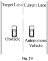
- Figs. 2A and 2B illustrate application scenes of a method for planning a speed of an autonomous vehicle according to an embodiment of the present invention, respectively.
- Figs. 2A and 2B illustrate a segment of two-lane road having an upward direction as a travelling direction.
- the autonomous vehicle travels on a right lane before a lane change, and travels on a left lane after the lane change, wherein the right lane may be referred to a 'current lane', and the left lane may be referred to a 'target lane'.
- the target lane may have the obstacles that affect the lane change of the autonomous vehicle, and the obstacles may include pedestrians, animals and vehicles, etc. on the lane.
- an autonomous vehicle is located in front of an obstacle before a lane change.
- multiple speed trajectories to be selected within a preset time range may be generated for the autonomous vehicle before the lane change; a cost function value of each of the speed trajectories to be selected is calculated, and a trajectory of speed to be selected with a minimum cost function value is selected as a planning speed trajectory.
- a planning travelling route trajectory may be obtained according to the planning speed trajectory, and the autonomous vehicle may change its lane according to the planning speed trajectory and the planning travelling route trajectory. For example, the trajectory from point A to point B in Fig. 2A is a route corresponding to the planning travelling route.
- a speed trajectory and a position trajectory of the obstacle within the preset time range may be predicted according to the current travelling condition of the obstacle and in combination with the current data, so as to obtain a predicted speed and a predicted position of the obstacle at each time point.
- the relative speed between the obstacle and the autonomous vehicle will affect the relative distance therebetween.
- the relative distance between the autonomous vehicle and the obstacle may be obtained according to the predicted speed and the predicted position of the obstacle; and then according to the relative distance, the cost function value of each of the speed trajectories to be selected may be calculated, so that the finally determined planning speed trajectory may be more reasonable.
- the speed before the lane change may be adjusted, thereby maintaining a lane change distance between the autonomous vehicle and the obstacle sufficient.
- the preset time range may be 8 seconds.
- An error of the speed trajectory may be increased after the preset 8 seconds, and thus the preset speed within 8 seconds may reduce the data redundancy and improve the accuracy of the planning travelling route and the planning speed.
- S300 may include:
- the relative speeds between the autonomous vehicle and the obstacle at the time point may be obtained, and then according to the relative speeds, an expected distance at the time point may be calculated.
- the expected distance may represent a safe distance away from the obstacle when the autonomous vehicle may successfully change the lane.
- a difference between the distance to be selected and the expected distance, from the autonomous vehicle to the obstacle will affect the cost function value of speed trajectory to be selected at the time point. For example, the cost function value decreases as the difference decreases.
- the cost function value of the speed trajectory to be selected may be obtained by accumulating the cost function value at each time point.
- the autonomous vehicle and the obstacle are side by side before a lane change.
- the speed of the autonomous vehicle may be adjusted, so that a safe distance from the autonomous vehicle to the obstacle in the target lane may be provided.
- S300 may include:
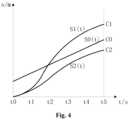
- the horizontal axis denotes a time (t) in a unit of second
- the longitudinal axis denotes a position (s) in a unit of meter.
- trajectories of speed to be selected v1(t) and v2(t) may be converted into travelling route trajectories s1(t) and s2(t), respectively, and s1(t) and s2(t) may be expressed in the route-time coordinate system.
- the predicted positions of the obstacle at each time point are mapped into the route-time coordinate system to obtain a plurality of discrete points, and a mapping route trajectory s0(t) of the obstacle may be obtained by fitting the plurality of discrete points.
- the preset time range ⁇ t includes multiple time points t0, t1, t2, t3, t4 and t5.
- S310 may include:
- a lane change corresponding to the speed trajectory to be selected may be determined as a lane change for overtaking or a lane change for yielding, according to a relative position between the autonomous vehicle and the obstacle at a last time point within the preset time range.
- C0 denotes a position of the obstacle at a last time point t5
- C1 denotes a position of the autonomous vehicle when travelling to the time point t5 based on the trajectory of speed to be selected v1(t)
- C2 denotes a position of the autonomous vehicle when travelling to the time point t5 based on the trajectory of speed to be selected v2(t).
- the first preset parameter x1, the second preset parameter x2, and the third preset parameter x3 may be preset according to actual experiences.
- x3 is set as a minimum distance allowed between the autonomous vehicle and the obstacle during the lane change.
- the planning speed may be more reasonable and a sufficient lane change distance from the obstacle in the target lane may be maintained before the lane change.
- the cost function value is calculated, in consideration of the safe distance between the autonomous vehicle and the obstacle, and the distance to be selected, it is possible to adjust the speed of the autonomous vehicle before the lane change in order to increase the distance from the obstacle, thereby creating an opportunity and a safe distance for the lane change, and then improving the success rate of the lane change (the merge into the traffic flow).
- Fig. 6 illustrates a structural block diagram of an apparatus for planning a speed of an autonomous vehicle according to an embodiment of the present invention. As illustrated in Fig. 6 , the apparatus includes:
- the calculating module 300 may include:
- the calculating module 300 may further include:
- the expected distance setting sub-module 310 may further include:
- the cost function value calculating sub-module 320 may further include:
- Fig. 8 illustrates a structural block diagram of an apparatus for planning a speed of an autonomous vehicle according to an embodiment of the present invention.
- the apparatus includes a memory 810 and a processor 820, wherein a computer program executable on the processor 820 is stored in the memory 810.
- the processor 820 executes the computer program, the method for planning a speed of an autonomous vehicle in the above embodiment is implemented.
- the apparatus further includes a communication interface 830 configured to communicate with an external device for a data interactive transmission.
- the memory 810 may include a high-speed random access memory (RAM), and may also include a non-volatile memory, such as at least one disk memory.
- RAM random access memory
- non-volatile memory such as at least one disk memory.
- the bus may be an Industry Standard Architecture (ISA) bus, a Peripheral Component (PCI) bus, an Extended Industry Standard Component (EISA) bus, or the like.
- ISA Industry Standard Architecture
- PCI Peripheral Component
- EISA Extended Industry Standard Component
- the bus may be divided into an address bus, a data bus, a control bus, and the like. For ease of illustration, only one bold line is shown in FIG. 8 , but it does not mean that there is only one bus or one type of bus.
- the memory 810, the processor 820, and the communication interface 830 may implement mutual communication through an internal interface.
- An embodiment of the present invention provides a non-volatile computer readable storage medium storing a computer program, which implements the method according to any one of the above embodiments when being executed by a processor.
- the description of the terms “one embodiment,” “some embodiments,” “an example,” “a specific example,” or “some examples” and the like means the specific characters, structures, materials, or characteristics described in connection with the embodiment or example are included in at least one embodiment or example of the present invention. Furthermore, the specific characters, structures, materials, or characteristics described may be combined in any suitable manner in any one or more of the embodiments or examples. In addition, different embodiments or examples described in this specification and characters of different embodiments or examples may be incorporated and combined by those skilled in the art without mutual contradiction.
- first and second are used for descriptive purposes only and are not to be construed as indicating or implying relative importance or implicitly indicating the number of indicated technical characters. Thus, characters defining “first” and “second” may explicitly or implicitly include at least one of the characters. In the description of the present invention, "a plurality of” means two or more, unless expressly limited otherwise.
- Logic and/or steps, which are represented in the flowcharts or otherwise described herein, for example, may be thought of as a sequencing listing of executable instructions for implementing logic functions, which may be embodied in any computer-readable medium, for use by or in connection with an instruction execution system, device, or apparatus (such as a computer-based system, a processor-included system, or other system that fetch instructions from an instruction execution system, device, or apparatus and execute the instructions).
- a "computer-readable medium” may be any device that may contain, store, communicate, propagate, or transport the program for use by or in connection with the instruction execution system, device, or apparatus.
- the computer-readable media include the following: electrical connections (electronic devices) having one or more wires, a portable computer disk cartridge (magnetic device), random access memory (RAM), read only memory (ROM), erasable programmable read only memory (EPROM or flash memory), optical fiber devices, and portable read only memory (CDROM).
- the computer-readable medium may even be paper or other suitable medium upon which the program may be printed, as it may be read, for example, by optical scanning of the paper or other medium, followed by editing, interpretation or, where appropriate, process otherwise to electronically obtain the program, which is then stored in a computer memory.
- each of the functional units in the embodiments of the present invention may be integrated in one processing module, or each of the units may exist alone physically, or two or more units may be integrated in one module.
- the above-mentioned integrated module may be implemented in the form of hardware or in the form of software functional module.
- the integrated module When the integrated module is implemented in the form of a software functional module and is sold or used as an independent product, the integrated module may also be stored in a non-volatile computer-readable storage medium.
- the storage medium may be a read only memory, a magnetic disk, an optical disk, or the like.
Landscapes
- Engineering & Computer Science (AREA)
- Automation & Control Theory (AREA)
- Transportation (AREA)
- Mechanical Engineering (AREA)
- Physics & Mathematics (AREA)
- Radar, Positioning & Navigation (AREA)
- Remote Sensing (AREA)
- General Physics & Mathematics (AREA)
- Human Computer Interaction (AREA)
- Aviation & Aerospace Engineering (AREA)
- Mathematical Physics (AREA)
- Electromagnetism (AREA)
- Theoretical Computer Science (AREA)
- Multimedia (AREA)
- Traffic Control Systems (AREA)
- Control Of Driving Devices And Active Controlling Of Vehicle (AREA)
- Control Of Position, Course, Altitude, Or Attitude Of Moving Bodies (AREA)
Description
- The present invention relates to automatic driving, and particularly to a method and an apparatus for planning a speed of an autonomous vehicle, and a storage medium.
- The autonomous vehicle includes vehicles travelling in an autonomous mode, such as driverless mode. The autonomous vehicle can liberate passengers, especially a driver, from driving. The autonomous vehicles can be navigated to various locations by using on-board sensors, so as to travel with minimal human-computer interactions or without any passengers. During a lane change of travelling, the autonomous vehicle moves from one lane to another lane, which is referred to as a merge into a traffic flow. Before the lane change, it is required to determine a travelling trajectory, including travelling speed, for the autonomous vehicle. If a determined speed is unreasonable, a traffic accident will occur.
-
US 2017/349183 A1 discloses a vehicle control system comprising an automated driving controller configured to execute an automated driving of the vehicle by automatically performing at least one of speed control and steering control of the vehicle, wherein the automated driving controller is provided with a trajectory generation part which is configured to generate a candidate of the trajectory based on the traveling mode determined. The trajectory candidates generated thereby may be represented by a plurality of trajectory points each of which including a speed component. A trajectory candidate generation part is required to give a target speed to each of the trajectory points. -
US 2018/148051 A1 discloses a further vehicle control system. - The embodiments of the present invention provide a method and apparatus for determining a speed of an autonomous vehicle, and a non-volatile computer-readable storage medium, so as to solve one or more technical problems in the existing technology.
- According to a first aspect, a method for planning a speed of an autonomous vehicle is provided according to the invention. The method includes:
- generating a plurality of speed trajectories to be selected for the autonomous vehicle before the autonomous vehicle changes a lane, wherein the speed trajectory to be selected comprises the speeds to be selected at a plurality of time points within a preset time range;
- obtaining predicted speeds and predicted positions of an obstacle at the plurality of time points;
- calculating a cost function value of each of the speed trajectories to be selected, according to the plurality of speed trajectories to be selected, the predicted speeds, and the predicted positions; and
- selecting a speed trajectory to be selected with a minimum cost function value, as a planning speed trajectory of the autonomous vehicle.
- Furthermore, calculating the calculating a cost function value of each of the speed trajectories to be selected, according to the plurality of speed trajectories to be selected, the predicted speeds, and the predicted positions includes:
- setting an expected distance at each time point, according to the speed to be selected of the autonomous vehicle at each time point and the predicted speed of the obstacle at each time point, wherein the expected distance is a safe distance from the autonomous vehicle to the obstacle;
- calculating a cost function value of the speed trajectory to be selected at each time point according to the expected distance and a distance to be selected at each time point, wherein the distance to be selected is a distance from the autonomous vehicle to the obstacle on the speed trajectory to be selected; and
- obtaining the cost function value of the speed trajectory to be selected according to the cost function value of the speed trajectory to be selected at each time point.
- Furthermore, the calculating a cost function value of each of the speed trajectories to be selected, according to the plurality of speed trajectories to be selected, the predicted speeds, and the predicted positions includes:
- generating a travelling route trajectory in a route-time coordinate system according to the speed trajectory to be selected, wherein a horizontal axis and a longitudinal axis of the route-time coordinate system denote a time and a position respectively; and
- mapping a plurality of predicted positions of the obstacle into the route-time coordinate system to obtain a mapping route trajectory of the obstacle, according to a correspondence relation to the time points.
- Furthermore, the setting an expected distance at each time point, according to the speed to be selected of the autonomous vehicle at each time point and the predicted speed of the obstacle at each time point includes:
- determining a lane change corresponding to the speed trajectory to be selected as a lane change for overtaking or a lane change for yielding, according to the travelling route trajectory and the mapping route trajectory;
- if the lane change is determined as a lane change for overtaking, calculating the expected distance at each time point according to a formula:
d_desire = v_obs×x1 + (v_obs-v_adc) ×x2+x3; wherein d_desire is an expected distance at the time point, v_obs is a predicted speed at the time point, v_adc is a speed to be selected at the time point, and x1, x2 and x3 are a first preset parameter, a second preset parameter and a third preset parameter, respectively. - Furthermore, the setting an expected distance at each time point, according to speed to be selected of the autonomous vehicle at each time point and predicted speed of an obstacle at each time point includes:
if the lane change is determined as a lane change for yielding, calculating the expected distance at each time point according to a formula:
- In an embodiment, the calculating a cost function value of the speed trajectory to be selected at each time point according to the expected distance and a distance to be selected at the each time point includes:
- determining the distance to be selected at each time point, according to the travelling route trajectory and the mapping route trajectory;
- calculating the cost function value of the speed trajectory to be selected at each time point according to a formula cost = max[0, - x4(d - d_desire)], wherein d is a distance to be selected at the time point, d_desire is an expected distance at the time point, and x4 is a fourth preset parameter.
- According to a second aspect, an apparatus for planning a speed of an autonomous vehicle is provided according to the invention. The apparatus includes:
- a generating module configured to generate a plurality of speed trajectories to be selected for the autonomous vehicle before the autonomous vehicle changes a lane, wherein the speed trajectory to be selected includes the speeds to be selected at a plurality of time points within a preset time range;
- an obtaining module configured to obtain predicted speeds and predicted positions of an obstacle at the plurality of time points;
- a calculating module configured to calculate a cost function value of each of the speed trajectories to be selected, according to the plurality of speed trajectories to be selected, the predicted speeds, and the predicted positions; and
- a selecting module configured to select a speed trajectory to be selected with a minimum cost function value, as a planning speed trajectory of the autonomous vehicle.
- Furthermore, the calculation module includes:
- an expected distance setting sub-module configured to set an expected distance at each time point, according to the speed to be selected of the autonomous vehicle at each time point and the predicted speed of the obstacle at each time point, wherein the expected distance is a safe distance from the autonomous vehicle to the obstacle;
- a cost function value calculating sub-module configured to calculate a cost function value of the speed trajectory to be selected at each time point according to the expected distance and a distance to be selected at each time point, wherein the distance to be selected is a distance from the autonomous vehicle to the obstacle on the speed trajectory to be selected; and
- a cost function value obtaining sub-module configured to obtain the cost function value of the speed trajectory to be selected according to the cost function value of the speed trajectory to be selected at each time point.
- Furthermore, the calculating module includes:
- a travelling route trajectory generating sub-module configured to generate a travelling route trajectory in a route-time coordinate system according to the speed trajectory to be selected, wherein a horizontal axis and a longitudinal axis of the route-time coordinate system denote a time and a position respectively; and
- a mapping route trajectory obtaining sub-module configured to map a plurality of predicted positions of the obstacle into the route-time coordinate system to obtain a mapping route trajectory of the obstacle, according to a correspondence relation to the time points.
- Furthermore, the expected distance calculating sub-module further includes:
- a judging unit configured to determine a lane change corresponding to the speed trajectory to be selected as a lane change for overtaking or a lane change for yielding, according to the travelling route trajectory and the mapping route trajectory; and
- a first calculating unit configured to, if the lane change is determined as a lane change for overtaking, calculate the expected distance at each time point according to a formula: d_desire = v_obs×x1 + (v_obs-v_adc) ×x2+x3; wherein d_desire is an expected distance for the time point, v_obs is a predicted speed at the time point, v_adc is a speed to be selected at the time point, and x1, x2 and x3 are a first preset parameter, a second preset parameter and a third preset parameter, respectively.
- Furthermore, the expected distance setting sub-module further includes:
a second calculating unit configured to, if the lane change is determined as a lane change for yielding, calculate the expected distance at each time point according to a formula: d_desire = v_obs×x1 + (v_adc-v_obs) ×x2+x3. - In an embodiment, the cost function value calculating sub-module includes:
- a determining unit configured to determine the distance to be selected at each time point, according to the travelling route trajectory and the mapping route trajectory; and
- a calculating unit configured to calculate the cost function value of the speed trajectory to be selected at each time point according to a formula cost = max[0,-x4(d-d_desire)], wherein d is a distance to be selected at the time point, d_desire is an expected distance at the time point, and x4 is a fourth preset parameter.
- According to a third aspect, a computer-readable storage medium is provided according to the invention, which is configured to store computer software instructions used by an apparatus for planning a speed of an autonomous vehicle, and including a program involved in performing any of the above methods for planning a speed of an autonomous vehicle.
- According to the above technical solutions, a planning speed may be more reasonable by generating a plurality of speed trajectories to be selected, calculating a cost function value of the speed trajectories to be selected according to relative positions and relative speeds between the autonomous vehicle and the obstacle, and determining a speed trajectory to be selected with a minimum cost function value as a planning speed of the autonomous vehicle before the autonomous vehicle changes a lane. Further, in the above technical solutions, the method for calculating the cost function value may adjust the speed of the autonomous vehicle before the autonomous vehicle changes a lane, so that the distance from the autonomous vehicle to the obstacle on the target lane is increased, thereby creating an opportunity and a safe distance for the lane change, and improving a success rate of the lane change.
- The above summary is for the purpose of the specification only and is not intended to be limiting in any way. In addition to the illustrative aspects, embodiments, and characters described above, further aspects, embodiments, and characters of the present invention will be readily understood by reference to the drawings and the following detailed description.
- In the drawings, unless otherwise specified, identical reference numerals will be used throughout the drawings to refer to identical or similar parts or elements. The drawings are not necessarily drawn to scale. It should be understood that these drawings depict only some embodiments disclosed in accordance with the present invention and are not to be considered as limiting the scope of the present invention.
-
Fig. 1 illustrates a flowchart of a method for planning a speed of an autonomous vehicle according to an embodiment of the present invention. -
Figs. 2A and2B illustrate example diagrams of a method for planning a speed of an autonomous vehicle according to an embodiment of the present invention, respectively. -
Fig. 3 illustrates a flowchart of a method for planning a speed of an autonomous vehicle according to one of embodiments of the present invention. -
Fig. 4 illustrates a schematic diagram of a travelling route trajectory and a mapping route trajectory in an embodiment of the present invention. -
Fig. 5 illustrates a flowchart of a method for planning a speed of an autonomous vehicle according to another one of embodiments of the present invention. -
Fig. 6 illustrates a structural block diagram of an apparatus for planning a speed of an autonomous vehicle according to an embodiment of the present invention. -
Fig. 7 illustrates a structural block diagram of an apparatus for planning a speed of an autonomous vehicle according to one of embodiments of the present invention. -
Fig. 8 illustrates a structural block diagram of an apparatus for planning a speed of an autonomous vehicle according to an embodiment of the present invention. - In the following, only certain exemplary embodiments are briefly described. As those skilled in the art would realize, the described embodiments may be modified in various different ways, all without departing from the scope of the present invention as defined in the claims.
Accordingly, the drawings and description are to be regarded as illustrative in nature and not restrictive. -
Fig. 1 illustrates a flowchart of a method for planning a speed of an autonomous vehicle according to an embodiment of the present invention. As illustrated inFig. 1 , the method may include the following steps: - S100: generating a plurality of speed trajectories to be selected for the autonomous vehicle before the autonomous vehicle changes a lane, wherein the speed trajectory to be selected comprises the speeds to be selected at a plurality of time points within a preset time range;
- S200: obtaining predicted speeds and predicted positions of an obstacle at the plurality of time points;
- S300: calculating a cost function value of each of the speed trajectories to be selected, according to the plurality of speed trajectories to be selected, the predicted speeds, and the predicted positions; and
- S400: selecting a speed trajectory to be selected with a minimum cost function value, as a planning speed trajectory of the autonomous vehicle.
- When the autonomous vehicle travels along a selected route, the speed of the autonomous vehicle at different time points may be determined so as to provide a speed trajectory for the autonomous vehicle. In this embodiment, the speed trajectory to be selected may be represented by a two-dimensional trajectory formed of speed and time. The preset time range is divided into a plurality of time points by a preset time interval. The speed trajectory to be selected is discretized to obtain a speed to be selected at the time point.
-
Figs. 2A and2B illustrate application scenes of a method for planning a speed of an autonomous vehicle according to an embodiment of the present invention, respectively.Figs. 2A and2B illustrate a segment of two-lane road having an upward direction as a travelling direction. InFigs. 2A and2B , the autonomous vehicle travels on a right lane before a lane change, and travels on a left lane after the lane change, wherein the right lane may be referred to a 'current lane', and the left lane may be referred to a 'target lane'. The target lane may have the obstacles that affect the lane change of the autonomous vehicle, and the obstacles may include pedestrians, animals and vehicles, etc. on the lane. - In
Fig. 2A , an autonomous vehicle is located in front of an obstacle before a lane change. In the embodiments of the present invention, multiple speed trajectories to be selected within a preset time range may be generated for the autonomous vehicle before the lane change; a cost function value of each of the speed trajectories to be selected is calculated, and a trajectory of speed to be selected with a minimum cost function value is selected as a planning speed trajectory. A planning travelling route trajectory may be obtained according to the planning speed trajectory, and the autonomous vehicle may change its lane according to the planning speed trajectory and the planning travelling route trajectory. For example, the trajectory from point A to point B inFig. 2A is a route corresponding to the planning travelling route. - In S200, a speed trajectory and a position trajectory of the obstacle within the preset time range may be predicted according to the current travelling condition of the obstacle and in combination with the current data, so as to obtain a predicted speed and a predicted position of the obstacle at each time point.
- The relative speed between the obstacle and the autonomous vehicle will affect the relative distance therebetween. Before the lane change, the relative distance between the autonomous vehicle and the obstacle may be obtained according to the predicted speed and the predicted position of the obstacle; and then according to the relative distance, the cost function value of each of the speed trajectories to be selected may be calculated, so that the finally determined planning speed trajectory may be more reasonable. The speed before the lane change may be adjusted, thereby maintaining a lane change distance between the autonomous vehicle and the obstacle sufficient.
- In one example, the preset time range may be 8 seconds. An error of the speed trajectory may be increased after the preset 8 seconds, and thus the preset speed within 8 seconds may reduce the data redundancy and improve the accuracy of the planning travelling route and the planning speed.
- In one embodiment, as illustrated in
Fig. 3 , S300 may include: - S310: setting an expected distance at each time point, according to the speed to be selected of the autonomous vehicle at each time point and the predicted speed of the obstacle at each time point, wherein the expected distance is a safe distance from the autonomous vehicle to the obstacle;
- S320: calculating a cost function value of the speed trajectory to be selected at each time point according to the expected distance and a distance to be selected at each time point, wherein the distance to be selected is a distance from the autonomous vehicle to the obstacle on the speed trajectory to be selected; and
- S330: obtaining the cost function value of the speed trajectory to be selected according to the cost function value of the speed trajectory to be selected at each time point.
- In S310, according to the speed to be selected at each time point and the predicted speed of the obstacle at the time point, the relative speeds between the autonomous vehicle and the obstacle at the time point may be obtained, and then according to the relative speeds, an expected distance at the time point may be calculated. The expected distance may represent a safe distance away from the obstacle when the autonomous vehicle may successfully change the lane.
- At a certain time point, a difference between the distance to be selected and the expected distance, from the autonomous vehicle to the obstacle, will affect the cost function value of speed trajectory to be selected at the time point. For example, the cost function value decreases as the difference decreases.
- In S330, the cost function value of the speed trajectory to be selected may be obtained by accumulating the cost function value at each time point.
- In
Fig. 2B , the autonomous vehicle and the obstacle are side by side before a lane change. According to the method of the embodiments of the present invention, before the lane change, the speed of the autonomous vehicle may be adjusted, so that a safe distance from the autonomous vehicle to the obstacle in the target lane may be provided. - In one embodiment, as illustrated in
Fig. 3 , S300 may include: - S340: generating a travelling route trajectory in a route-time coordinate system according to the speed trajectory to be selected, wherein a horizontal axis and a longitudinal axis of the route-time coordinate system denote a time and a position respectively; and
- S350: mapping a plurality of predicted positions of the obstacle into the route-time coordinate system to obtain a mapping route trajectory of the obstacle, according to a correspondence relation to the time points.
- In one example, as illustrated in
Fig. 4 , in the route-time coordinate system, the horizontal axis denotes a time (t) in a unit of second, and the longitudinal axis denotes a position (s) in a unit of meter. In S311, according to a formula s=v×t, trajectories of speed to be selected v1(t) and v2(t) may be converted into travelling route trajectories s1(t) and s2(t), respectively, and s1(t) and s2(t) may be expressed in the route-time coordinate system. The predicted positions of the obstacle at each time point are mapped into the route-time coordinate system to obtain a plurality of discrete points, and a mapping route trajectory s0(t) of the obstacle may be obtained by fitting the plurality of discrete points. The preset time range Δt includes multiple time points t0, t1, t2, t3, t4 and t5. - In one embodiment, as illustrated in
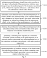
Fig. 5 , S310 may include: - S311: determining a lane change corresponding to the speed trajectory to be selected as a lane change for overtaking or a lane change for yielding, according to the travelling route trajectory and the mapping route trajectory;
- S312: if the lane change is determined as a lane change for overtaking, calculating the expected distance at each time point according to a formula:
d_desire = v_obs×x1 + (v_obs-v_adc) ×x2+x3; wherein d_desire is an expected distance at the time point, v_obs is a predicted speed at the time point, v_adc is a speed to be selected at the time point, and x1, x2 and x3 are a first preset parameter, a second preset parameter and a third preset parameter, respectively; and - S313: if the lane change is determined as a lane change for yielding, calculating the expected distance at each time point according to a formula:

- In S311, a lane change corresponding to the speed trajectory to be selected may be determined as a lane change for overtaking or a lane change for yielding, according to a relative position between the autonomous vehicle and the obstacle at a last time point within the preset time range.
- Next, the description is continued with reference to
Fig. 4 . InFig. 4 , C0 denotes a position of the obstacle at a last time point t5; C1 denotes a position of the autonomous vehicle when travelling to the time point t5 based on the trajectory of speed to be selected v1(t); C2 denotes a position of the autonomous vehicle when travelling to the time point t5 based on the trajectory of speed to be selected v2(t). When C1 is located above C0, it is determined that the lane change expressed by the trajectory of speed to be selected v1(t) is a lane change for overtaking; and when C2 is located below C0, it is determined that the lane change expressed by the trajectory of speed to be selected v2(t) is a lane change for yielding. - In S312 and S313, the first preset parameter x1, the second preset parameter x2, and the third preset parameter x3 may be preset according to actual experiences. For example, x3 is set as a minimum distance allowed between the autonomous vehicle and the obstacle during the lane change.
- In one embodiment, in S320, the distance to be selected at each time point is determined according to the travelling route trajectory and the mapping route trajectory; the cost function value of the speed trajectory to be selected at the time point is calculated, according to a formula cost = max[0, - x4(d - d_desire)], wherein d is a distance to be selected at the time point, d_desire is an expected distance at the time point, and x4 is a fourth preset parameter.
- In this embodiment, the cost function value of the speed trajectory to be selected at each time point is calculated according to the formula cost = max[0, - x4(d - d_desire)], and then the cost function value of the speed trajectory to be selected is calculated.
- In summary, in the method for planning the speed of the autonomous vehicle according to the embodiments of the present invention, by generating a plurality of speed trajectories to be selected; calculating a cost function value of each of the speed trajectories to be selected, according to the relative positions and the relative speeds between the autonomous vehicle and the obstacle; and then determining a speed trajectory to be selected with a minimum cost function value as a planning speed trajectory for the lane change of the autonomous vehicle, the planning speed may be more reasonable and a sufficient lane change distance from the obstacle in the target lane may be maintained before the lane change.
- Further, when the cost function value is calculated, in consideration of the safe distance between the autonomous vehicle and the obstacle, and the distance to be selected, it is possible to adjust the speed of the autonomous vehicle before the lane change in order to increase the distance from the obstacle, thereby creating an opportunity and a safe distance for the lane change, and then improving the success rate of the lane change (the merge into the traffic flow).
- In addition, upon planning a speed, different calculating methods of the cost function value adopted for the overtaking lane change and the yielding lane change lead to a more accuracy.
-
Fig. 6 illustrates a structural block diagram of an apparatus for planning a speed of an autonomous vehicle according to an embodiment of the present invention. As illustrated inFig. 6 , the apparatus includes: - a
generating module 100 configured to generate a plurality of speed trajectories to be selected for the autonomous vehicle before the autonomous vehicle changes a lane, wherein the speed trajectory to be selected comprises the speeds to be selected at a plurality of time points within a preset time range; - an obtaining
module 200 configured to obtain predicted speeds and predicted positions of an obstacle at the plurality of time points; - a calculating
module 300 configured to calculate a cost function value of each of the speed trajectories to be selected, according to the plurality of speed trajectories to be selected, the predicted speeds, and the predicted positions; and - a selecting
module 400 configured to select a speed trajectory to be selected with a minimum cost function value, as a planning speed trajectory of the autonomous vehicle . - In one embodiment, as illustrated in
Fig. 7 , the calculatingmodule 300 may include: - an expected distance setting sub-module 310 configured to set an expected distance at each time point, according to the speed to be selected of the autonomous vehicle at each time point and the predicted speed of the obstacle at each time point, wherein the expected distance is a safe distance from the autonomous vehicle to the obstacle;
- a cost function value calculating sub-module 320 configured to calculate a cost function value of the speed trajectory to be selected at each time point according to the expected distance and a distance to be selected at each time point, wherein the distance to be selected is a distance from the autonomous vehicle to the obstacle on the speed trajectory to be selected; and
- a cost function value obtaining sub-module 330 configured to obtain the cost function value of the speed trajectory to be selected according to the cost function value of the speed trajectory to be selected at each time point.
- In one embodiment, as illustrated in
Fig. 7 , the calculatingmodule 300 may further include: - a travelling route
trajectory generating unit 340 configured to generate a travelling route trajectory in a route-time coordinate system according to the speed trajectory to be selected, wherein a horizontal axis and a longitudinal axis of the route-time coordinate system denote a time and a position respectively; - a mapping route
trajectory obtaining unit 350 configured to map a plurality of predicted positions of the obstacle into the route-time coordinate system to obtain a mapping route trajectory of the obstacle, according to a correspondence relation to the time points. - In one embodiment, the expected distance setting sub-module 310 may further include:
- a judging unit configured to determine a lane change corresponding to the speed trajectory to be selected as a lane change for overtaking or a lane change for yielding, according to the travelling route trajectory and the mapping route trajectory; and
- a first calculating unit configured to, if the lane change is determined as a lane change for overtaking, calculate the expected distance at each time point according to a formula: d_desire = v_obs×x1 + (v_obs - v_adc) ×x2+x3; wherein d_desire is an expected distance for the time point, v_obs is a predicted speed at the time point, v_adc is a speed to be selected at the time point, and x1, x2 and x3 are a first preset parameter, a second preset parameter and a third preset parameter, respectively; and
- a second calculating unit configured to, if the lane change is determined as a lane change for yielding, calculate the expected distance at each time point according to a formula: d_desire = v_obs×x1 + (v_adc - v_obs) ×x2+x3.
- In one embodiment, the cost function value calculating sub-module 320 may further include:
- a determining unit configured to determine the distance to be selected at each time point, according to the travelling route trajectory and the mapping route trajectory; and
- a calculating unit configured to calculate the cost function value of the speed trajectory to be selected at each time point according to a formula cost = max[0, - x4(d - d_desire)], wherein d is a distance to be selected at the time point, d_desire is an expected distance at the time point, and x4 is a fourth preset parameter.
- The function of each of the modules in the apparatus according to the embodiments of the present invention can refer to corresponding descriptions in the above method, and will not be repeated here.
-
Fig. 8 illustrates a structural block diagram of an apparatus for planning a speed of an autonomous vehicle according to an embodiment of the present invention. As illustrated inFig. 8 , the apparatus includes amemory 810 and aprocessor 820, wherein a computer program executable on theprocessor 820 is stored in thememory 810. When theprocessor 820 executes the computer program, the method for planning a speed of an autonomous vehicle in the above embodiment is implemented. There may be one ormore memories 810 and one ormore processors 820. - The apparatus further includes a
communication interface 830 configured to communicate with an external device for a data interactive transmission. - The
memory 810 may include a high-speed random access memory (RAM), and may also include a non-volatile memory, such as at least one disk memory. - If the
memory 810, theprocessor 820, and thecommunication interface 830 are implemented independently, thememory 810, theprocessor 820, and thecommunication interface 830 may be connected to each other through a bus and communicate with one another. The bus may be an Industry Standard Architecture (ISA) bus, a Peripheral Component (PCI) bus, an Extended Industry Standard Component (EISA) bus, or the like. The bus may be divided into an address bus, a data bus, a control bus, and the like. For ease of illustration, only one bold line is shown inFIG. 8 , but it does not mean that there is only one bus or one type of bus. - Optionally, in a specific implementation, if the
memory 810, theprocessor 820, and thecommunication interface 830 are integrated on one chip, thememory 820, theprocessor 810, and thecommunication interface 830 may implement mutual communication through an internal interface. - An embodiment of the present invention provides a non-volatile computer readable storage medium storing a computer program, which implements the method according to any one of the above embodiments when being executed by a processor.
- In the description of the specification, the description of the terms "one embodiment," "some embodiments," "an example," "a specific example," or "some examples" and the like means the specific characters, structures, materials, or characteristics described in connection with the embodiment or example are included in at least one embodiment or example of the present invention. Furthermore, the specific characters, structures, materials, or characteristics described may be combined in any suitable manner in any one or more of the embodiments or examples. In addition, different embodiments or examples described in this specification and characters of different embodiments or examples may be incorporated and combined by those skilled in the art without mutual contradiction.
- In addition, the terms "first" and "second" are used for descriptive purposes only and are not to be construed as indicating or implying relative importance or implicitly indicating the number of indicated technical characters. Thus, characters defining "first" and "second" may explicitly or implicitly include at least one of the characters. In the description of the present invention, "a plurality of" means two or more, unless expressly limited otherwise.
- Any process or method descriptions described in flowcharts or otherwise herein may be understood as representing modules, segments or portions of code that include one or more executable instructions for implementing the steps of a particular logic function or process. The scope of the preferred embodiments of the present invention includes additional implementations where the functions may not be performed in the order shown or discussed, including according to the functions involved, in substantially simultaneous or in reverse order, which should be understood by those skilled in the art to which the embodiment of the present invention belongs.
- Logic and/or steps, which are represented in the flowcharts or otherwise described herein, for example, may be thought of as a sequencing listing of executable instructions for implementing logic functions, which may be embodied in any computer-readable medium, for use by or in connection with an instruction execution system, device, or apparatus (such as a computer-based system, a processor-included system, or other system that fetch instructions from an instruction execution system, device, or apparatus and execute the instructions). For the purposes of this specification, a "computer-readable medium" may be any device that may contain, store, communicate, propagate, or transport the program for use by or in connection with the instruction execution system, device, or apparatus. More specific examples (not a non-exhaustive list) of the computer-readable media include the following: electrical connections (electronic devices) having one or more wires, a portable computer disk cartridge (magnetic device), random access memory (RAM), read only memory (ROM), erasable programmable read only memory (EPROM or flash memory), optical fiber devices, and portable read only memory (CDROM). In addition, the computer-readable medium may even be paper or other suitable medium upon which the program may be printed, as it may be read, for example, by optical scanning of the paper or other medium, followed by editing, interpretation or, where appropriate, process otherwise to electronically obtain the program, which is then stored in a computer memory.
- It should be understood that various portions of the present invention may be implemented by hardware, software, firmware, or a combination thereof. In the above embodiments, multiple steps or methods may be implemented in software or firmware stored in memory and executed by a suitable instruction execution system. For example, if implemented in hardware, as in another embodiment, they may be implemented using any one or a combination of the following techniques well known in the art: discrete logic circuits having a logic gate circuit for implementing logic functions on data signals, application specific integrated circuits with suitable combinational logic gate circuits, programmable gate arrays (PGA), field programmable gate arrays (FPGAs), and the like.
- Those skilled in the art may understand that all or some of the steps carried in the methods in the foregoing embodiments may be implemented by a program instructing relevant hardware. The program may be stored in a non-volatile computer-readable storage medium, and when executed, one of the steps of the method embodiment or a combination thereof is included.
- In addition, each of the functional units in the embodiments of the present invention may be integrated in one processing module, or each of the units may exist alone physically, or two or more units may be integrated in one module. The above-mentioned integrated module may be implemented in the form of hardware or in the form of software functional module. When the integrated module is implemented in the form of a software functional module and is sold or used as an independent product, the integrated module may also be stored in a non-volatile computer-readable storage medium. The storage medium may be a read only memory, a magnetic disk, an optical disk, or the like.
- The foregoing descriptions are merely specific embodiments of the present invention, but not intended to limit the protection scope of the present invention. Those skilled in the art may easily conceive of various changes or modifications within the technical scope disclosed herein, all these should be covered within the protection scope of the present invention. Therefore, the protection scope of the present application should be subject to the protection scope of the claims.
Claims (6)
- A method for planning a speed of an autonomous vehicle, comprising:generating (S100) a plurality of speed trajectories to be selected for the autonomous vehicle before the autonomous vehicle changes a lane, wherein the speed trajectory to be selected comprises the speeds to be selected at a plurality of time points within a preset time range;obtaining (S200) predicted speeds and predicted positions of an obstacle at the plurality of time points;calculating (S300) a cost function value of each of the speed trajectories to be selected, according to the plurality of speed trajectories to be selected, the predicted speeds, and the predicted positions; andselecting (S400) a speed trajectory to be selected with a minimum cost function value, as a planning speed trajectory of the autonomous vehicle;wherein the calculating (S300) a cost function value of each of the speed trajectories to be selected, according to the plurality of speed trajectories to be selected, the predicted speeds, and the predicted positions comprises:setting (S310) an expected distance at each time point, according to the speed to be selected of the autonomous vehicle at each time point and the predicted speed of the obstacle at each time point, wherein the expected distance is a safe distance from the autonomous vehicle to the obstacle;calculating (S320) a cost function value of the speed trajectory to be selected at each time point according to the expected distance and a distance to be selected at each time point, wherein the distance to be selected is a distance from the autonomous vehicle to the obstacle on the speed trajectory to be selected; andobtaining (S330) the cost function value of the speed trajectory to be selected according to the cost function value of the speed trajectory to be selected at each time point;wherein the calculating (S300) a cost function value of each of the speed trajectories to be selected, according to the plurality of speed trajectories to be selected, the predicted speeds, and the predicted positions comprises:generating (S340) a travelling route trajectory in a route-time coordinate system according to the speed trajectory to be selected, wherein a horizontal axis and a longitudinal axis of the route-time coordinate system denote a time and a position respectively; andmapping (S350) a plurality of predicted positions of the obstacle into the route-time coordinate system to obtain a mapping route trajectory of the obstacle, according to a correspondence relation to the time points;characterized in thatthe setting (S310) an expected distance at each time point, according to the speed to be selected of the autonomous vehicle at each time point and the predicted speed of the obstacle at each time point comprises:determining (S311) a lane change corresponding to the speed trajectory to be selected as a lane change for overtaking or a lane change for yielding, according to the travelling route trajectory and the mapping route trajectory;if the lane change is determined as a lane change for overtaking, calculating (S312) the expected distance at each time point according to a formula:
d_desire = v_obs×x1 + (v_obs - v_adc) ×x2+x3; wherein d_desire is an expected distance at the time point, v_obs is a predicted speed at the time point, v_adc is a speed to be selected at the time point, and x1, x2 and x3 are a first preset parameter, a second preset parameter and a third preset parameter, respectively; andif the lane change is determined as a lane change for yielding, calculating (S313) the expected distance at each time point according to another formula:
- The method according to claim 1, wherein the calculating a cost function value of the speed trajectory to be selected at each time point according to the expected distance and a distance to be selected at each time point comprises:determining the distance to be selected at each time point, according to the travelling route trajectory and the mapping route trajectory;calculating the cost function value of the speed trajectory to be selected at each time point according to a formula cost = max[0, - x4(d - d_desire)], wherein d is a distance to be selected at the time point, d_desire is an expected distance at the time point, and x4 is a fourth preset parameter.
- An apparatus for planning a speed of an autonomous vehicle, comprising:a generating module (100) configured to generate a plurality of speed trajectories to be selected for the autonomous vehicle before the autonomous vehicle changes a lane, wherein the speed trajectory to be selected comprises the speeds to be selected at a plurality of time points within a preset time range;an obtaining module (200) configured to obtain predicted speeds and predicted positions of an obstacle at the plurality of time points;a calculating module (300) configured to calculate a cost function value of each of the speed trajectories to be selected, according to the plurality of speed trajectories to be selected, the predicted speeds, and the predicted positions; anda selecting module (400) configured to select a speed trajectory to be selected with a minimum cost function value, as a planning speed trajectory of the autonomous vehicle;wherein the calculating module (300) comprises:an expected distance setting sub-module (310) configured to set an expected distance at each time point, according to the speed to be selected of the autonomous vehicle at each time point and the predicted speed of the obstacle at each time point, wherein the expected distance is a safe distance from the autonomous vehicle to the obstacle;a cost function value calculating sub-module (320) configured to calculate a cost function value of the speed trajectory to be selected at each time point according to the expected distance and a distance to be selected at each time point, wherein the distance to be selected is a distance from the autonomous vehicle to the obstacle on the speed trajectory to be selected; anda cost function value obtaining sub-module (330) configured to obtain the cost function value of the speed trajectory to be selected according to the cost function value of the speed trajectory to be selected at each time point;wherein the calculating module comprises:a travelling route trajectory generating sub-module (340) configured to generate a travelling route trajectory in a route-time coordinate system according to the speed trajectory to be selected, wherein a horizontal axis and a longitudinal axis of the route-time coordinate system denote a time and a position respectively; anda mapping route trajectory obtaining sub-module (350) configured to map a plurality of predicted positions of the obstacle into the route-time coordinate system to obtain a mapping route trajectory of the obstacle, according to a correspondence relation to the time points;characterized in thatthe expected distance setting sub-module (310) further comprises:a judging unit configured to determine a lane change corresponding to the speed trajectory to be selected as a lane change for overtaking or a lane change for yielding, according to the travelling route trajectory and the mapping route trajectory;a first calculating unit configured to, if the lane change is determined as a lane change for overtaking, calculate the expected distance at each time point according to a formula: d_desire = v_obs×x1 + (v_obs - v_adc) ×x2+x3; wherein d_desire is an expected distance for the time point, v_obs is a predicted speed at the time point, v_adc is a speed to be selected at the time point, and x1, x2 and x3 are a first preset parameter, a second preset parameter and a third preset parameter, respectively; anda second calculating unit configured to, if the lane change is determined as a lane change for yielding, calculate the expected distance at each time point according to a formula: d_desire = v_obs×x1 + (v_adc - v_obs) ×x2+x3.
- The apparatus according to claim 3, wherein the cost function value calculating sub-module (320) comprises:a determining unit configured to determine the distance to be selected at each time point, according to the travelling route trajectory and the mapping route trajectory; anda calculating unit configured to calculate the cost function value of the speed trajectory to be selected at each time point according to a formula cost = max[0, - x4(d - d_desire)], wherein d is a distance to be selected at the time point, d_desire is an expected distance at the time point, and x4 is a fourth preset parameter.
- A computer-readable storage medium storing a computer program, wherein the computer program, when executed by a processor, implements the method according to claim 1 or claim 2.
- A computer program product, comprising computer program instructions, that when executed by a processor, cause the processor to implement the method of claim 1 or claim 2.
Applications Claiming Priority (1)
| Application Number | Priority Date | Filing Date | Title |
|---|---|---|---|
| CN201910135454.2A CN109712421B (en) | 2019-02-22 | 2019-02-22 | Method, apparatus and storage medium for speed planning of autonomous vehicles |
Publications (2)
| Publication Number | Publication Date |
|---|---|
| EP3699053A1 EP3699053A1 (en) | 2020-08-26 |
| EP3699053B1 true EP3699053B1 (en) | 2025-03-19 |
Family
ID=66264773
Family Applications (1)
| Application Number | Title | Priority Date | Filing Date |
|---|---|---|---|
| EP20275038.6A Active EP3699053B1 (en) | 2019-02-22 | 2020-02-12 | Method and apparatus for planning speed of autonomous vehicle, and storage medium |
Country Status (5)
| Country | Link |
|---|---|
| US (1) | US11718318B2 (en) |
| EP (1) | EP3699053B1 (en) |
| JP (1) | JP7000640B2 (en) |
| KR (2) | KR20200103541A (en) |
| CN (1) | CN109712421B (en) |
Families Citing this family (63)
| Publication number | Priority date | Publication date | Assignee | Title |
|---|---|---|---|---|
| US10962973B2 (en) * | 2018-01-30 | 2021-03-30 | Uatc, Llc | Autonomous vehicle safe stop |
| US11643115B2 (en) * | 2019-05-31 | 2023-05-09 | Waymo Llc | Tracking vanished objects for autonomous vehicles |
| JP7199337B2 (en) * | 2019-11-15 | 2023-01-05 | 株式会社東芝 | Position estimation device, position estimation method and program |
| US11561543B2 (en) * | 2019-12-11 | 2023-01-24 | Baidu Usa Llc | Speed planning using a speed planning guideline for idle speed of autonomous driving vehicles |
| CN111002993B (en) * | 2019-12-23 | 2021-06-22 | 苏州智加科技有限公司 | Automatic driving low-oil-consumption movement planning method and system based on scene recognition |
| RU2757234C2 (en) * | 2019-12-25 | 2021-10-12 | Общество с ограниченной ответственностью "Яндекс Беспилотные Технологии" | Method and system for calculating data for controlling the operation of a self-driving car |
| US11755014B2 (en) * | 2019-12-31 | 2023-09-12 | Uatc, Llc | Jointly learnable behavior and trajectory planning for autonomous vehicles |
| CN111038501B (en) * | 2019-12-31 | 2021-04-27 | 北京三快在线科技有限公司 | Control method and device of unmanned equipment |
| CN111081046B (en) * | 2020-01-03 | 2022-01-14 | 阿波罗智能技术(北京)有限公司 | Method, device, electronic equipment and medium for automatically changing lane of driving vehicle |
| DE112021000216T5 (en) * | 2020-02-19 | 2022-11-03 | Nvidia Corporation | Behavior planning for autonomous vehicles |
| US11377120B1 (en) * | 2020-02-28 | 2022-07-05 | Uatc, Llc | Autonomous vehicle control based on risk-based interactions |
| CN111338346B (en) * | 2020-03-05 | 2022-10-21 | 中国第一汽车股份有限公司 | Automatic driving control method and device, vehicle and storage medium |
| DE102020108857A1 (en) * | 2020-03-31 | 2021-09-30 | Daimler Ag | Method for planning a target trajectory |
| CN111439264B (en) * | 2020-04-03 | 2021-06-11 | 东南大学 | Implementation method of lane change control model based on man-machine hybrid driving |
| CN111650945B (en) * | 2020-06-28 | 2023-10-24 | 北京智行者科技股份有限公司 | Dynamic obstacle anticollision method |
| CN112068544B (en) * | 2020-07-20 | 2024-06-04 | 上海擎朗智能科技有限公司 | Scheduling method, device, equipment and storage medium of autonomous mobile device |
| JP7587368B2 (en) * | 2020-08-04 | 2024-11-20 | 株式会社三共 | Gaming Machines |
| JP7587369B2 (en) * | 2020-08-04 | 2024-11-20 | 株式会社三共 | Gaming Machines |
| JP7597530B2 (en) * | 2020-08-07 | 2024-12-10 | 株式会社三共 | Gaming Machines |
| EP4196859B1 (en) * | 2020-08-12 | 2026-04-29 | Autonomous Solutions, Inc. | Autonomous safety rider |
| CN112577506B (en) * | 2020-10-30 | 2023-04-07 | 上汽大众汽车有限公司 | Automatic driving local path planning method and system |
| CN112498355B (en) * | 2020-11-02 | 2022-11-25 | 浙江吉利控股集团有限公司 | Speed planning method and device |
| CN114537381B (en) * | 2020-11-24 | 2024-05-31 | 宇通客车股份有限公司 | Lane obstacle avoidance method and device for automatic driving vehicle |
| US11472435B2 (en) * | 2020-11-30 | 2022-10-18 | Automotive Research & Testing Center | Trajectory determination method for a vehicle |
| CN112526999B (en) * | 2020-12-22 | 2023-04-28 | 北京百度网讯科技有限公司 | Speed planning method, device, electronic equipment and storage medium |
| US12139173B2 (en) * | 2021-01-19 | 2024-11-12 | Baidu Usa Llc | Dynamic model evaluation package for autonomous driving vehicles |
| CN112937605B (en) * | 2021-03-22 | 2023-03-10 | 京东鲲鹏(江苏)科技有限公司 | Unmanned vehicle driving data determination method and device, unmanned vehicle and storage medium |
| CN114103938B (en) * | 2021-03-23 | 2024-07-16 | 京东鲲鹏(江苏)科技有限公司 | Method, device and storage medium for controlling longitudinal movement of vehicle |
| CN113022586B (en) * | 2021-04-14 | 2022-08-02 | 福瑞泰克智能系统有限公司 | Vehicle behavior prediction method and device and storage medium |
| CN113071520B (en) * | 2021-04-16 | 2024-01-16 | 阿波罗智联(北京)科技有限公司 | Vehicle running control method and device |
| CN115246416B (en) * | 2021-05-13 | 2023-09-26 | 上海仙途智能科技有限公司 | Trajectory prediction method, device, equipment and computer-readable storage medium |
| US11975742B2 (en) * | 2021-05-25 | 2024-05-07 | Ford Global Technologies, Llc | Trajectory consistency measurement for autonomous vehicle operation |
| CN114030469B (en) * | 2021-06-18 | 2022-08-02 | 东南大学 | Multi-vehicle collaborative trajectory planning and path tracking method |
| CN113320544B (en) * | 2021-06-30 | 2022-11-11 | 上海商汤临港智能科技有限公司 | Vehicle driving behavior planning method and device, electronic equipment and storage medium |
| CN113479217B (en) * | 2021-07-26 | 2022-07-29 | 惠州华阳通用电子有限公司 | Lane changing and obstacle avoiding method and system based on automatic driving |
| CN113570595B (en) * | 2021-08-12 | 2023-06-20 | 上汽大众汽车有限公司 | Vehicle Trajectory Prediction Method and Optimization Method of Vehicle Trajectory Prediction Model |
| CN113703453A (en) * | 2021-08-24 | 2021-11-26 | 京东鲲鹏(江苏)科技有限公司 | Method and device for determining driving track, electronic equipment and storage medium |
| CN113799798B (en) * | 2021-08-27 | 2023-07-11 | 北京百度网讯科技有限公司 | Method and device for determining running track of vehicle, electronic equipment and memory |
| CN113961002B (en) * | 2021-09-09 | 2023-10-03 | 浙江零跑科技股份有限公司 | An active lane changing planning method based on structured road sampling |
| CN113978465A (en) * | 2021-09-28 | 2022-01-28 | 阿波罗智能技术(北京)有限公司 | Lane-changing track planning method, device, equipment and storage medium |
| CN113823123B (en) * | 2021-09-28 | 2022-07-01 | 合肥工业大学 | A vehicle obstacle avoidance warning method and device based on discrete point trajectory fitting |
| US20230126540A1 (en) * | 2021-10-26 | 2023-04-27 | Tusimple, Inc. | Systems and methods for handling cut-in traffic for autonomous driving |
| CN114179815B (en) * | 2021-12-29 | 2023-08-18 | 阿波罗智联(北京)科技有限公司 | Method and device for determining vehicle driving track, vehicle, electronic equipment and medium |
| CN114454883B (en) * | 2022-02-28 | 2023-09-15 | 重庆长安汽车股份有限公司 | Longitudinal planning method for creating safe lane change condition based on peripheral vehicle prediction |
| CN116142230A (en) * | 2022-03-18 | 2023-05-23 | 北京智行者科技股份有限公司 | Speed planning method and device, control device, vehicle, storage medium |
| CN114633750B (en) * | 2022-03-29 | 2024-08-02 | 山东交通学院 | Channel switching process extraction and channel switching characteristic analysis method based on unsupervised technology |
| CN115218902B (en) * | 2022-04-02 | 2024-02-02 | 广州汽车集团股份有限公司 | Track planning method, device, equipment and storage medium |
| CN115060279B (en) * | 2022-06-08 | 2024-04-16 | 合众新能源汽车股份有限公司 | Path planning method, path planning device, electronic equipment and computer readable medium |
| US20240001926A1 (en) * | 2022-06-29 | 2024-01-04 | Ford Global Technologies, Llc | Controlling a vehicle lane-change |
| US20240005066A1 (en) * | 2022-06-30 | 2024-01-04 | Baidu Usa Llc | Decoupled prediction evaluation |
| CN115092180A (en) * | 2022-06-30 | 2022-09-23 | 广州文远知行科技有限公司 | Vehicle meeting method and device, computer equipment and storage medium |
| CN115230739B (en) * | 2022-08-12 | 2026-04-24 | 广州小鹏自动驾驶科技有限公司 | Vehicle speed planning methods, devices, vehicles and storage media |
| CN115447578B (en) * | 2022-08-30 | 2024-09-24 | 重庆长安汽车股份有限公司 | Method and device for automatic lane changing of vehicle |
| US12344257B2 (en) * | 2022-10-10 | 2025-07-01 | Waymo Llc | Methods and systems for adjusting vehicle behavior based on estimated unintentional lateral movements |
| US20240169111A1 (en) * | 2022-11-18 | 2024-05-23 | Gm Cruise Holdings Llc | Parameterizing hot starts to maximize test repeatability |
| CN116039629B (en) * | 2023-01-29 | 2025-07-01 | 广州小鹏自动驾驶科技有限公司 | Vehicle control method, device, vehicle and storage medium |
| CN116279489B (en) * | 2023-04-28 | 2025-07-04 | 重庆长安汽车股份有限公司 | Vehicle lane change control method, device, equipment and storage medium |
| CN117302224B (en) * | 2023-11-30 | 2024-02-23 | 上海鉴智其迹科技有限公司 | Lane changing method, automatic driving method, device and vehicle |
| CN117601867B (en) * | 2024-01-18 | 2024-06-14 | 杭州鉴智机器人科技有限公司 | Vehicle lane changing method, vehicle lane changing device, storage medium and vehicle control system |
| KR102952083B1 (en) * | 2024-04-24 | 2026-04-14 | 주식회사 레인보우로보틱스 | Method for moving path of mobile robot and mobile robot performing the same |
| US20250333062A1 (en) * | 2024-04-30 | 2025-10-30 | Zoox, Inc. | Lane changing based on a lane change right-of-way cost |
| CN118560505B (en) * | 2024-07-31 | 2024-11-29 | 清华大学苏州汽车研究院(相城) | Vehicle trajectory prediction method, device, storage medium and electronic terminal |
| CN120482074B (en) * | 2025-07-21 | 2025-09-16 | 纽劢科技(上海)有限公司 | Vehicle control method and vehicle |
Citations (1)
| Publication number | Priority date | Publication date | Assignee | Title |
|---|---|---|---|---|
| US20180148051A1 (en) * | 2018-01-24 | 2018-05-31 | GM Global Technology Operations LLC | Systems and methods for unprotected maneuver mitigation in autonomous vehicles |
Family Cites Families (113)
| Publication number | Priority date | Publication date | Assignee | Title |
|---|---|---|---|---|
| JP3998855B2 (en) * | 1999-05-18 | 2007-10-31 | 三菱電機株式会社 | Dangerous approach prevention device |
| DE10132681C1 (en) | 2001-07-05 | 2002-08-22 | Bosch Gmbh Robert | Method for classifying an obstacle using pre-crash sensor signals |
| US7212330B2 (en) | 2004-03-22 | 2007-05-01 | Angstrom, Inc. | Three-dimensional imaging system for pattern recognition |
| DE102006060905A1 (en) * | 2006-12-20 | 2008-06-26 | Deutsches Zentrum für Luft- und Raumfahrt e.V. | Method for supporting longitudinal guiding of ego vehicle following guiding vehicle during speed deceleration produced by guiding vehicle, involves transferring speed delay of guiding vehicle at adjacent ego vehicle |
| JP4730378B2 (en) | 2007-12-25 | 2011-07-20 | トヨタ自動車株式会社 | Course evaluation device and course evaluation method |
| US20090232388A1 (en) | 2008-03-12 | 2009-09-17 | Harris Corporation | Registration of 3d point cloud data by creation of filtered density images |
| US8611585B2 (en) | 2008-04-24 | 2013-12-17 | GM Global Technology Operations LLC | Clear path detection using patch approach |
| US8605947B2 (en) | 2008-04-24 | 2013-12-10 | GM Global Technology Operations LLC | Method for detecting a clear path of travel for a vehicle enhanced by object detection |
| US8126642B2 (en) | 2008-10-24 | 2012-02-28 | Gray & Company, Inc. | Control and systems for autonomously driven vehicles |
| CN101441076B (en) | 2008-12-29 | 2010-06-02 | 东软集团股份有限公司 | Method and device for detecting barrier |
| KR101054479B1 (en) * | 2009-03-27 | 2011-08-05 | 국방과학연구소 | Regional Route Planning Apparatus and Method for Unmanned Vehicles Using Directional Speed Maps for Each Direction |
| US8260539B2 (en) | 2010-05-12 | 2012-09-04 | GM Global Technology Operations LLC | Object and vehicle detection and tracking using 3-D laser rangefinder |
| WO2012001755A1 (en) | 2010-07-02 | 2012-01-05 | 株式会社ソニー・コンピュータエンタテインメント | Information processing system, information processing device, and information processing method |
| US9562778B2 (en) | 2011-06-03 | 2017-02-07 | Robert Bosch Gmbh | Combined radar and GPS localization system |
| CN103258338A (en) | 2012-02-16 | 2013-08-21 | 克利特股份有限公司 | Method and system for driving simulated virtual environments with real data |
| CN102663196B (en) | 2012-04-17 | 2014-04-16 | 中南大学 | Automobile crane hoisting simulation method on basis of virtual reality |
| US9255989B2 (en) | 2012-07-24 | 2016-02-09 | Toyota Motor Engineering & Manufacturing North America, Inc. | Tracking on-road vehicles with sensors of different modalities |
| JP5527382B2 (en) | 2012-10-12 | 2014-06-18 | トヨタ自動車株式会社 | Driving support system and control device |
| US8788134B1 (en) * | 2013-01-04 | 2014-07-22 | GM Global Technology Operations LLC | Autonomous driving merge management system |
| US9082014B2 (en) | 2013-03-14 | 2015-07-14 | The Nielsen Company (Us), Llc | Methods and apparatus to estimate demography based on aerial images |
| JP5993784B2 (en) | 2013-04-18 | 2016-09-14 | 株式会社豊田中央研究所 | Route correction device |
| CN104376297B (en) | 2013-08-12 | 2017-06-23 | 株式会社理光 | The detection method and device of the line style Warning Mark on road |
| JP5812061B2 (en) | 2013-08-22 | 2015-11-11 | 株式会社デンソー | Target detection apparatus and program |
| JP5919243B2 (en) | 2013-10-18 | 2016-05-18 | 本田技研工業株式会社 | Driving training apparatus and driving training method |
| CN103914830B (en) | 2014-02-22 | 2017-02-01 | 小米科技有限责任公司 | Straight line detection method and device |
| CN104899855A (en) | 2014-03-06 | 2015-09-09 | 株式会社日立制作所 | Three-dimensional obstacle detection method and apparatus |
| CN104933856B (en) | 2014-03-17 | 2017-08-25 | 径卫视觉科技(上海)有限公司 | Road conditions real-time evaluation system and method |
| CN104020674B (en) | 2014-04-21 | 2017-01-25 | 华南农业大学 | Matlab simulation visualized platform of vehicle Bug obstacle avoidance algorithm |
| JP6354282B2 (en) | 2014-04-21 | 2018-07-11 | トヨタ自動車株式会社 | Driving assistance device |
| CN104183014B (en) | 2014-08-13 | 2017-01-18 | 浙江大学 | An information labeling method having high fusion degree and oriented to city augmented reality |
| KR101687073B1 (en) | 2014-10-22 | 2016-12-15 | 주식회사 만도 | Apparatus for esimating tunnel height and method thereof |
| CN104331910B (en) | 2014-11-24 | 2017-06-16 | 沈阳建筑大学 | A kind of track obstacle detecting system based on machine vision |
| CN104457569B (en) | 2014-11-27 | 2017-06-16 | 大连理工大学 | A kind of large-scale composite board geometric parameter vision measuring method |
| CN104590259B (en) * | 2015-01-07 | 2015-08-26 | 福州华鹰重工机械有限公司 | A kind of transitional search method and system |
| JP6112123B2 (en) | 2015-01-19 | 2017-04-12 | トヨタ自動車株式会社 | Automatic driving device |
| JP2016143240A (en) * | 2015-02-02 | 2016-08-08 | 株式会社豊田中央研究所 | Lane change optimization device and program |
| JP2016149109A (en) * | 2015-02-10 | 2016-08-18 | 国立大学法人金沢大学 | Vehicle travel control device |
| CN104950883A (en) | 2015-05-14 | 2015-09-30 | 西安电子科技大学 | Mobile robot route planning method based on distance grid map |
| TWI630132B (en) | 2015-06-04 | 2018-07-21 | 國立虎尾科技大學 | 3D animation car accident scene reconstruction method |
| CN104933708A (en) | 2015-06-07 | 2015-09-23 | 浙江大学 | Barrier detection method in vegetation environment based on multispectral and 3D feature fusion |
| CN104931977B (en) | 2015-06-11 | 2017-08-25 | 同济大学 | A kind of obstacle recognition method for intelligent vehicle |
| JP6376059B2 (en) * | 2015-07-06 | 2018-08-22 | トヨタ自動車株式会社 | Control device for autonomous driving vehicle |
| US20170092000A1 (en) | 2015-09-25 | 2017-03-30 | Moshe Schwimmer | Method and system for positioning a virtual object in a virtual simulation environment |
| JP6304894B2 (en) * | 2015-10-28 | 2018-04-04 | 本田技研工業株式会社 | Vehicle control device, vehicle control method, and vehicle control program |
| JP6409744B2 (en) * | 2015-11-06 | 2018-10-24 | 株式会社アドヴィックス | Vehicle travel support device |
| JP6464075B2 (en) | 2015-11-11 | 2019-02-06 | 日本電信電話株式会社 | What-if simulation apparatus, method, and program |
| US10591600B2 (en) | 2015-11-30 | 2020-03-17 | Luminar Technologies, Inc. | Lidar system with distributed laser and multiple sensor heads |
| CN105549597B (en) * | 2016-02-04 | 2018-06-26 | 同济大学 | A kind of unmanned vehicle dynamic path planning method based on environmental uncertainty |
| CN105761308B (en) | 2016-02-29 | 2018-09-07 | 武汉大学 | A kind of occlusion area building facade method for reconstructing of ground LiDAR and image data fusion |
| EP4091894B1 (en) | 2016-03-03 | 2024-11-06 | Volvo Truck Corporation | A vehicle with autonomous driving capability |
| US10690495B2 (en) | 2016-03-14 | 2020-06-23 | Canon Kabushiki Kaisha | Ranging apparatus and moving object capable of high-accuracy ranging |
| CN107305383A (en) | 2016-04-22 | 2017-10-31 | 上海慧流云计算科技有限公司 | A kind of method of automatic obstacle-avoiding and the robot using this method |
| KR102485479B1 (en) | 2016-04-26 | 2023-01-05 | 현대모비스 주식회사 | Method and apparatus for automatic lane changing |
| CN105844600B (en) | 2016-04-27 | 2018-03-16 | 北京航空航天大学 | A kind of extraterrestrial target three-dimensional point cloud fairing denoising method |
| CN105957145A (en) | 2016-04-29 | 2016-09-21 | 百度在线网络技术(北京)有限公司 | Road barrier identification method and device |
| US9760806B1 (en) | 2016-05-11 | 2017-09-12 | TCL Research America Inc. | Method and system for vision-centric deep-learning-based road situation analysis |
| JP2017214035A (en) | 2016-06-02 | 2017-12-07 | 本田技研工業株式会社 | Vehicle control system, vehicle control method, and vehicle control program |
| CN106114507B (en) * | 2016-06-21 | 2018-04-03 | 百度在线网络技术(北京)有限公司 | Local path planning method and device for intelligent vehicle |
| CN106204457A (en) | 2016-07-19 | 2016-12-07 | 科盾科技股份有限公司 | A kind of method for capture target and catching device |
| CN106364486B (en) * | 2016-09-08 | 2019-08-27 | 江苏大学 | A lane-changing control method for intelligent vehicles based on hazard analysis |
| CN107818293A (en) | 2016-09-14 | 2018-03-20 | 北京百度网讯科技有限公司 | Method and apparatus for handling cloud data |
| WO2018053833A1 (en) | 2016-09-26 | 2018-03-29 | 深圳市锐明技术股份有限公司 | Method and apparatus for quickly detecting paired lane lines |
| JP6548691B2 (en) | 2016-10-06 | 2019-07-24 | 株式会社アドバンスド・データ・コントロールズ | Image generation system, program and method, simulation system, program and method |
| CN107976688A (en) | 2016-10-25 | 2018-05-01 | 菜鸟智能物流控股有限公司 | Obstacle detection method and related device |
| RO132599A2 (en) | 2016-11-23 | 2018-05-30 | Centrul It Pentru Ştiinţă Şi Tehnologie S.R.L. | Modular equipment for road inspection, passable way and adjacent area included, meant to be mounted to ordinary vehicles |
| CN106681318A (en) | 2016-12-09 | 2017-05-17 | 重庆长安汽车股份有限公司 | Vehicle safety control system and method for lane line detection temporary loss in automatic drive |
| CN106599832A (en) | 2016-12-09 | 2017-04-26 | 重庆邮电大学 | Method for detecting and recognizing various types of obstacles based on convolution neural network |
| CN106627592A (en) * | 2016-12-12 | 2017-05-10 | 深圳市元征科技股份有限公司 | Early warning method, device and system for vehicle traveling |
| CN106585622A (en) | 2016-12-20 | 2017-04-26 | 奇瑞汽车股份有限公司 | Method for driving automatically under road construction condition and smart car |
| US10139830B2 (en) * | 2016-12-29 | 2018-11-27 | Automotive Research & Testing Center | Automatic lane following control system and method for vehicles |
| JP6804991B2 (en) | 2017-01-05 | 2020-12-23 | 株式会社東芝 | Information processing equipment, information processing methods, and information processing programs |
| CN106845412B (en) | 2017-01-20 | 2020-07-10 | 百度在线网络技术(北京)有限公司 | Obstacle identification method and device, computer equipment and readable medium |
| WO2018138584A1 (en) | 2017-01-26 | 2018-08-02 | Mobileye Vision Technologies Ltd. | Vehicle navigation based on aligned image and lidar information |
| US11036233B2 (en) * | 2017-02-02 | 2021-06-15 | Uatc, Llc | Adaptive vehicle motion control system |
| US10730531B1 (en) * | 2017-02-02 | 2020-08-04 | Uatc, Llc | Machine-learning based vehicle motion control system |
| CN106919908B (en) | 2017-02-10 | 2020-07-28 | 百度在线网络技术(北京)有限公司 | Obstacle identification method and device, computer equipment and readable medium |
| CN108492356A (en) | 2017-02-13 | 2018-09-04 | 苏州宝时得电动工具有限公司 | Augmented reality system and its control method |
| CN106874597B (en) * | 2017-02-16 | 2019-12-13 | 北理慧动(常熟)车辆科技有限公司 | highway overtaking behavior decision method applied to automatic driving vehicle |
| CN108459588B (en) * | 2017-02-22 | 2020-09-11 | 腾讯科技(深圳)有限公司 | Automatic driving method and device, vehicle |
| US11142203B2 (en) * | 2017-02-27 | 2021-10-12 | Ford Global Technologies, Llc | Cooperative vehicle navigation |
| CN106940933B (en) * | 2017-03-08 | 2019-05-24 | 北京理工大学 | A method of intelligent vehicle decision-making based on intelligent transportation system |
| CN106997049B (en) | 2017-03-14 | 2020-07-03 | 奇瑞汽车股份有限公司 | A method and device for detecting obstacles based on laser point cloud data |
| CN106971624B (en) * | 2017-04-25 | 2020-05-08 | 东软集团股份有限公司 | Overtaking early warning method and device |
| CN107161155B (en) * | 2017-04-27 | 2019-04-12 | 大连理工大学 | A method and system for vehicle cooperative lane changing based on artificial neural network |
| CN107103627B (en) | 2017-04-27 | 2020-12-11 | 深圳市天双科技有限公司 | A method for calibrating external parameters of automotive panoramic camera based on lane lines |
| CN107139923B (en) | 2017-05-11 | 2019-07-09 | 中科院微电子研究所昆山分所 | A kind of ACC decision-making technique and system |
| US10591920B2 (en) * | 2017-05-24 | 2020-03-17 | Qualcomm Incorporated | Holistic planning with multiple intentions for self-driving cars |
| JP6521487B2 (en) | 2017-06-06 | 2019-05-29 | マツダ株式会社 | Vehicle control device |
| CN107315411B (en) * | 2017-07-04 | 2020-04-21 | 合肥工业大学 | A lane-changing trajectory planning method for unmanned vehicles based on vehicle-vehicle cooperation |
| US10953881B2 (en) * | 2017-09-07 | 2021-03-23 | Tusimple, Inc. | System and method for automated lane change control for autonomous vehicles |
| CN107672589B (en) | 2017-09-26 | 2019-05-28 | 畅加风行(苏州)智能科技有限公司 | A kind of track of vehicle real-time predicting method and device based on GPR Detection Data |
| CN107657237B (en) | 2017-09-28 | 2020-03-31 | 东南大学 | Automobile collision detection method and system based on deep learning |
| CN107659774B (en) | 2017-09-30 | 2020-10-13 | 北京拙河科技有限公司 | Video imaging system and video processing method based on multi-scale camera array |
| CN107678306B (en) | 2017-10-09 | 2021-04-16 | 驭势(上海)汽车科技有限公司 | Dynamic scene information recording and simulation playback method, device, equipment and medium |
| US10019011B1 (en) * | 2017-10-09 | 2018-07-10 | Uber Technologies, Inc. | Autonomous vehicles featuring machine-learned yield model |
| CN207407892U (en) | 2017-11-03 | 2018-05-25 | 河南思维轨道交通技术研究院有限公司 | Navigation data System of Synchronous Processing and navigation system |
| CN107832806A (en) | 2017-12-06 | 2018-03-23 | 四川知创空间孵化器管理有限公司 | A kind of car plate type identification method and system |
| CN108323190B (en) | 2017-12-15 | 2022-07-29 | 深圳市道通智能航空技术股份有限公司 | Obstacle avoidance method and device and unmanned aerial vehicle |
| CN107992050B (en) | 2017-12-20 | 2021-05-11 | 广州汽车集团股份有限公司 | Method and device for local path motion planning of unmanned vehicle |
| CN108156419A (en) | 2017-12-22 | 2018-06-12 | 湖南源信光电科技股份有限公司 | More focal length lens linkage imaging camera machine system based on multiple features combining and Camshift algorithms |
| CN108010360A (en) | 2017-12-27 | 2018-05-08 | 中电海康集团有限公司 | A kind of automatic Pilot context aware systems based on bus or train route collaboration |
| US20190204842A1 (en) * | 2018-01-02 | 2019-07-04 | GM Global Technology Operations LLC | Trajectory planner with dynamic cost learning for autonomous driving |
| CN107993512A (en) | 2018-01-03 | 2018-05-04 | 深圳市欣横纵技术股份有限公司 | One seed nucleus security Table Top Tool systems and application method |
| US20180150081A1 (en) * | 2018-01-24 | 2018-05-31 | GM Global Technology Operations LLC | Systems and methods for path planning in autonomous vehicles |
| CN108256506B (en) | 2018-02-14 | 2020-11-24 | 北京市商汤科技开发有限公司 | Method and device for detecting object in video and computer storage medium |
| CN108519773B (en) * | 2018-03-07 | 2020-01-14 | 西安交通大学 | Path planning method for unmanned vehicle in structured environment |
| CN108583578B (en) * | 2018-04-26 | 2019-12-31 | 北京领骏科技有限公司 | Lane decision method based on multi-objective decision matrix for automatic driving vehicle |
| CN108646735A (en) | 2018-05-02 | 2018-10-12 | 新石器龙码(北京)科技有限公司 | A kind of control method and device of unmanned vehicle |
| CN108460980B (en) * | 2018-05-11 | 2020-09-29 | 西南交通大学 | Calculation method of optimal off-ramp intent generation point for autonomous vehicles |
| JP7194755B2 (en) * | 2018-05-31 | 2022-12-22 | ニッサン ノース アメリカ,インク | Trajectory plan |
| CN109101022A (en) | 2018-08-09 | 2018-12-28 | 北京智行者科技有限公司 | A kind of working path update method |
| US11208096B2 (en) * | 2018-11-02 | 2021-12-28 | Zoox, Inc. | Cost scaling in trajectory generation |
| US11048260B2 (en) * | 2018-11-02 | 2021-06-29 | Zoox, Inc. | Adaptive scaling in trajectory generation |
-
2019
- 2019-02-22 CN CN201910135454.2A patent/CN109712421B/en active Active
-
2020
- 2020-02-11 US US16/787,729 patent/US11718318B2/en active Active
- 2020-02-12 EP EP20275038.6A patent/EP3699053B1/en active Active
- 2020-02-18 KR KR1020200019757A patent/KR20200103541A/en not_active Ceased
- 2020-02-18 JP JP2020025125A patent/JP7000640B2/en active Active
-
2021
- 2021-11-18 KR KR1020210159597A patent/KR102446971B1/en active Active
Patent Citations (1)
| Publication number | Priority date | Publication date | Assignee | Title |
|---|---|---|---|---|
| US20180148051A1 (en) * | 2018-01-24 | 2018-05-31 | GM Global Technology Operations LLC | Systems and methods for unprotected maneuver mitigation in autonomous vehicles |
Also Published As
| Publication number | Publication date |
|---|---|
| EP3699053A1 (en) | 2020-08-26 |
| CN109712421B (en) | 2021-06-04 |
| US11718318B2 (en) | 2023-08-08 |
| JP7000640B2 (en) | 2022-01-19 |
| CN109712421A (en) | 2019-05-03 |
| US20200269873A1 (en) | 2020-08-27 |
| KR20210144635A (en) | 2021-11-30 |
| JP2020132149A (en) | 2020-08-31 |
| KR20200103541A (en) | 2020-09-02 |
| KR102446971B1 (en) | 2022-09-22 |
Similar Documents
| Publication | Publication Date | Title |
|---|---|---|
| EP3699053A1 (en) | Method and apparatus for planning speed of autonomous vehicle, and storage medium | |
| EP3699048B1 (en) | Travelling track prediction method and device for vehicle | |
| EP3702230B1 (en) | Method and apparatus for planning travelling path, and vehicle | |
| US11780463B2 (en) | Method, apparatus and server for real-time learning of travelling strategy of driverless vehicle | |
| EP3888985B1 (en) | Lane changing method and system for autonomous vehicles, and vehicle | |
| EP3699888A1 (en) | Interaction method and apparatus between vehicles | |
| CN109814576B (en) | Method, apparatus and storage medium for speed planning of autonomous vehicles | |
| US20200262436A1 (en) | Method, device, and terminal apparatus for invoking automatic driving reference line | |
| EP3699890A2 (en) | Information processing method and apparatus, and storage medium | |
| CN109814575B (en) | Lane changing route planning method and device for automatic driving vehicle and terminal | |
| CN113561992B (en) | Automatic driving vehicle track generation method, device, terminal equipment and medium | |
| CN117885764B (en) | Vehicle track planning method and device, vehicle and storage medium | |
| CN109724614B (en) | Method, apparatus and storage medium for speed planning of autonomous vehicles | |
| CN109955851B (en) | Lane changing decision and track planning method | |
| CN115507871B (en) | Method and device for planning path of automatic driving vehicle, vehicle and medium | |
| CN116476840A (en) | Lane changing driving method, device, equipment and storage medium | |
| CN116443049A (en) | Anti-collision method and device for automatic driving vehicle | |
| US12283088B2 (en) | Method and system for determining a driving corridor | |
| CN118457598A (en) | Method and device for calculating vehicle drivable area, vehicle and storage medium | |
| CN118306425A (en) | Automatic driving decision method, device, equipment, storage medium and program product | |
| CN115465295B (en) | Method, device, vehicle and storage medium for predicting future trajectory of vehicles at intersections | |
| CN111176285A (en) | Method and device for planning travel path, vehicle and readable storage medium | |
| CN115097826A (en) | Vehicle turning track planning method and device | |
| TWI750762B (en) | Hybrid planniing method in autonomous vehicles and system thereof | |
| CN121157922A (en) | Method for controlling lane change of vehicle, driving assistance system and vehicle |
Legal Events
| Date | Code | Title | Description |
|---|---|---|---|
| PUAI | Public reference made under article 153(3) epc to a published international application that has entered the european phase |
Free format text: ORIGINAL CODE: 0009012 |
|
| STAA | Information on the status of an ep patent application or granted ep patent |
Free format text: STATUS: REQUEST FOR EXAMINATION WAS MADE |
|
| 17P | Request for examination filed |
Effective date: 20200310 |
|
| AK | Designated contracting states |
Kind code of ref document: A1 Designated state(s): AL AT BE BG CH CY CZ DE DK EE ES FI FR GB GR HR HU IE IS IT LI LT LU LV MC MK MT NL NO PL PT RO RS SE SI SK SM TR |
|
| AX | Request for extension of the european patent |
Extension state: BA ME |
|
| RAP1 | Party data changed (applicant data changed or rights of an application transferred) |
Owner name: APOLLO INTELLIGENT DRIVING TECHNOLOGY (BEIJING) CO., LTD. |
|
| STAA | Information on the status of an ep patent application or granted ep patent |
Free format text: STATUS: EXAMINATION IS IN PROGRESS |
|
| 17Q | First examination report despatched |
Effective date: 20221222 |
|
| GRAP | Despatch of communication of intention to grant a patent |
Free format text: ORIGINAL CODE: EPIDOSNIGR1 |
|
| STAA | Information on the status of an ep patent application or granted ep patent |
Free format text: STATUS: GRANT OF PATENT IS INTENDED |
|
| INTG | Intention to grant announced |
Effective date: 20240924 |
|
| GRAS | Grant fee paid |
Free format text: ORIGINAL CODE: EPIDOSNIGR3 |
|
| GRAA | (expected) grant |
Free format text: ORIGINAL CODE: 0009210 |
|
| STAA | Information on the status of an ep patent application or granted ep patent |
Free format text: STATUS: THE PATENT HAS BEEN GRANTED |
|
| P01 | Opt-out of the competence of the unified patent court (upc) registered |
Free format text: CASE NUMBER: APP_1447/2025 Effective date: 20250109 |
|
| AK | Designated contracting states |
Kind code of ref document: B1 Designated state(s): AL AT BE BG CH CY CZ DE DK EE ES FI FR GB GR HR HU IE IS IT LI LT LU LV MC MK MT NL NO PL PT RO RS SE SI SK SM TR |
|
| REG | Reference to a national code |
Ref country code: GB Ref legal event code: FG4D |
|
| REG | Reference to a national code |
Ref country code: CH Ref legal event code: EP |
|
| REG | Reference to a national code |
Ref country code: DE Ref legal event code: R096 Ref document number: 602020047875 Country of ref document: DE |
|
| REG | Reference to a national code |
Ref country code: IE Ref legal event code: FG4D |
|
| PG25 | Lapsed in a contracting state [announced via postgrant information from national office to epo] |
Ref country code: RS Free format text: LAPSE BECAUSE OF FAILURE TO SUBMIT A TRANSLATION OF THE DESCRIPTION OR TO PAY THE FEE WITHIN THE PRESCRIBED TIME-LIMIT Effective date: 20250619 |
|
| PG25 | Lapsed in a contracting state [announced via postgrant information from national office to epo] |
Ref country code: FI Free format text: LAPSE BECAUSE OF FAILURE TO SUBMIT A TRANSLATION OF THE DESCRIPTION OR TO PAY THE FEE WITHIN THE PRESCRIBED TIME-LIMIT Effective date: 20250319 |
|
| REG | Reference to a national code |
Ref country code: LT Ref legal event code: MG9D |
|
| PG25 | Lapsed in a contracting state [announced via postgrant information from national office to epo] |
Ref country code: NO Free format text: LAPSE BECAUSE OF FAILURE TO SUBMIT A TRANSLATION OF THE DESCRIPTION OR TO PAY THE FEE WITHIN THE PRESCRIBED TIME-LIMIT Effective date: 20250619 |
|
| PG25 | Lapsed in a contracting state [announced via postgrant information from national office to epo] |
Ref country code: HR Free format text: LAPSE BECAUSE OF FAILURE TO SUBMIT A TRANSLATION OF THE DESCRIPTION OR TO PAY THE FEE WITHIN THE PRESCRIBED TIME-LIMIT Effective date: 20250319 |
|
| PG25 | Lapsed in a contracting state [announced via postgrant information from national office to epo] |
Ref country code: LV Free format text: LAPSE BECAUSE OF FAILURE TO SUBMIT A TRANSLATION OF THE DESCRIPTION OR TO PAY THE FEE WITHIN THE PRESCRIBED TIME-LIMIT Effective date: 20250319 |
|
| PG25 | Lapsed in a contracting state [announced via postgrant information from national office to epo] |
Ref country code: GR Free format text: LAPSE BECAUSE OF FAILURE TO SUBMIT A TRANSLATION OF THE DESCRIPTION OR TO PAY THE FEE WITHIN THE PRESCRIBED TIME-LIMIT Effective date: 20250620 Ref country code: BG Free format text: LAPSE BECAUSE OF FAILURE TO SUBMIT A TRANSLATION OF THE DESCRIPTION OR TO PAY THE FEE WITHIN THE PRESCRIBED TIME-LIMIT Effective date: 20250319 |
|
| REG | Reference to a national code |
Ref country code: NL Ref legal event code: MP Effective date: 20250319 |
|
| REG | Reference to a national code |
Ref country code: AT Ref legal event code: MK05 Ref document number: 1776738 Country of ref document: AT Kind code of ref document: T Effective date: 20250319 |
|
| PG25 | Lapsed in a contracting state [announced via postgrant information from national office to epo] |
Ref country code: NL Free format text: LAPSE BECAUSE OF FAILURE TO SUBMIT A TRANSLATION OF THE DESCRIPTION OR TO PAY THE FEE WITHIN THE PRESCRIBED TIME-LIMIT Effective date: 20250319 |
|
| PG25 | Lapsed in a contracting state [announced via postgrant information from national office to epo] |
Ref country code: SE Free format text: LAPSE BECAUSE OF FAILURE TO SUBMIT A TRANSLATION OF THE DESCRIPTION OR TO PAY THE FEE WITHIN THE PRESCRIBED TIME-LIMIT Effective date: 20250319 |
|
| PG25 | Lapsed in a contracting state [announced via postgrant information from national office to epo] |
Ref country code: SM Free format text: LAPSE BECAUSE OF FAILURE TO SUBMIT A TRANSLATION OF THE DESCRIPTION OR TO PAY THE FEE WITHIN THE PRESCRIBED TIME-LIMIT Effective date: 20250319 |
|
| PG25 | Lapsed in a contracting state [announced via postgrant information from national office to epo] |
Ref country code: PT Free format text: LAPSE BECAUSE OF FAILURE TO SUBMIT A TRANSLATION OF THE DESCRIPTION OR TO PAY THE FEE WITHIN THE PRESCRIBED TIME-LIMIT Effective date: 20250721 Ref country code: ES Free format text: LAPSE BECAUSE OF FAILURE TO SUBMIT A TRANSLATION OF THE DESCRIPTION OR TO PAY THE FEE WITHIN THE PRESCRIBED TIME-LIMIT Effective date: 20250319 |
|
| PG25 | Lapsed in a contracting state [announced via postgrant information from national office to epo] |
Ref country code: IT Free format text: LAPSE BECAUSE OF FAILURE TO SUBMIT A TRANSLATION OF THE DESCRIPTION OR TO PAY THE FEE WITHIN THE PRESCRIBED TIME-LIMIT Effective date: 20250319 Ref country code: PL Free format text: LAPSE BECAUSE OF FAILURE TO SUBMIT A TRANSLATION OF THE DESCRIPTION OR TO PAY THE FEE WITHIN THE PRESCRIBED TIME-LIMIT Effective date: 20250319 |
|
| PG25 | Lapsed in a contracting state [announced via postgrant information from national office to epo] |
Ref country code: AT Free format text: LAPSE BECAUSE OF FAILURE TO SUBMIT A TRANSLATION OF THE DESCRIPTION OR TO PAY THE FEE WITHIN THE PRESCRIBED TIME-LIMIT Effective date: 20250319 |
|
| PG25 | Lapsed in a contracting state [announced via postgrant information from national office to epo] |
Ref country code: CZ Free format text: LAPSE BECAUSE OF FAILURE TO SUBMIT A TRANSLATION OF THE DESCRIPTION OR TO PAY THE FEE WITHIN THE PRESCRIBED TIME-LIMIT Effective date: 20250319 Ref country code: EE Free format text: LAPSE BECAUSE OF FAILURE TO SUBMIT A TRANSLATION OF THE DESCRIPTION OR TO PAY THE FEE WITHIN THE PRESCRIBED TIME-LIMIT Effective date: 20250319 |
|
| PG25 | Lapsed in a contracting state [announced via postgrant information from national office to epo] |
Ref country code: RO Free format text: LAPSE BECAUSE OF FAILURE TO SUBMIT A TRANSLATION OF THE DESCRIPTION OR TO PAY THE FEE WITHIN THE PRESCRIBED TIME-LIMIT Effective date: 20250319 |
|
| PG25 | Lapsed in a contracting state [announced via postgrant information from national office to epo] |
Ref country code: SK Free format text: LAPSE BECAUSE OF FAILURE TO SUBMIT A TRANSLATION OF THE DESCRIPTION OR TO PAY THE FEE WITHIN THE PRESCRIBED TIME-LIMIT Effective date: 20250319 |
|
| PG25 | Lapsed in a contracting state [announced via postgrant information from national office to epo] |
Ref country code: IS Free format text: LAPSE BECAUSE OF FAILURE TO SUBMIT A TRANSLATION OF THE DESCRIPTION OR TO PAY THE FEE WITHIN THE PRESCRIBED TIME-LIMIT Effective date: 20250719 |
|
| REG | Reference to a national code |
Ref country code: DE Ref legal event code: R097 Ref document number: 602020047875 Country of ref document: DE |
|
| PG25 | Lapsed in a contracting state [announced via postgrant information from national office to epo] |
Ref country code: DK Free format text: LAPSE BECAUSE OF FAILURE TO SUBMIT A TRANSLATION OF THE DESCRIPTION OR TO PAY THE FEE WITHIN THE PRESCRIBED TIME-LIMIT Effective date: 20250319 |
|
| PLBE | No opposition filed within time limit |
Free format text: ORIGINAL CODE: 0009261 |
|
| STAA | Information on the status of an ep patent application or granted ep patent |
Free format text: STATUS: NO OPPOSITION FILED WITHIN TIME LIMIT |
|
| REG | Reference to a national code |
Ref country code: CH Ref legal event code: L10 Free format text: ST27 STATUS EVENT CODE: U-0-0-L10-L00 (AS PROVIDED BY THE NATIONAL OFFICE) Effective date: 20260128 |
|
| 26N | No opposition filed |
Effective date: 20251222 |
|
| PGFP | Annual fee paid to national office [announced via postgrant information from national office to epo] |
Ref country code: DE Payment date: 20260217 Year of fee payment: 7 |