EP3699043B1 - Transporter docking device, power exchange transporter and docking method - Google Patents
Transporter docking device, power exchange transporter and docking method Download PDFInfo
- Publication number
- EP3699043B1 EP3699043B1 EP18867611.8A EP18867611A EP3699043B1 EP 3699043 B1 EP3699043 B1 EP 3699043B1 EP 18867611 A EP18867611 A EP 18867611A EP 3699043 B1 EP3699043 B1 EP 3699043B1
- Authority
- EP
- European Patent Office
- Prior art keywords
- transporter
- guiding
- positioning
- disposed
- engaging device
- Prior art date
- Legal status (The legal status is an assumption and is not a legal conclusion. Google has not performed a legal analysis and makes no representation as to the accuracy of the status listed.)
- Active
Links
Images

Classifications
-
- B—PERFORMING OPERATIONS; TRANSPORTING
- B60—VEHICLES IN GENERAL
- B60L—PROPULSION OF ELECTRICALLY-PROPELLED VEHICLES; SUPPLYING ELECTRIC POWER FOR AUXILIARY EQUIPMENT OF ELECTRICALLY-PROPELLED VEHICLES; ELECTRODYNAMIC BRAKE SYSTEMS FOR VEHICLES IN GENERAL; MAGNETIC SUSPENSION OR LEVITATION FOR VEHICLES; MONITORING OPERATING VARIABLES OF ELECTRICALLY-PROPELLED VEHICLES; ELECTRIC SAFETY DEVICES FOR ELECTRICALLY-PROPELLED VEHICLES
- B60L53/00—Methods of charging batteries, specially adapted for electric vehicles; Charging stations or on-board charging equipment therefor; Exchange of energy storage elements in electric vehicles
- B60L53/80—Exchanging energy storage elements, e.g. removable batteries
-
- B—PERFORMING OPERATIONS; TRANSPORTING
- B60—VEHICLES IN GENERAL
- B60S—SERVICING, CLEANING, REPAIRING, SUPPORTING, LIFTING, OR MANOEUVRING OF VEHICLES, NOT OTHERWISE PROVIDED FOR
- B60S5/00—Servicing, maintaining, repairing, or refitting of vehicles
- B60S5/06—Supplying batteries to, or removing batteries from, vehicles
-
- Y—GENERAL TAGGING OF NEW TECHNOLOGICAL DEVELOPMENTS; GENERAL TAGGING OF CROSS-SECTIONAL TECHNOLOGIES SPANNING OVER SEVERAL SECTIONS OF THE IPC; TECHNICAL SUBJECTS COVERED BY FORMER USPC CROSS-REFERENCE ART COLLECTIONS [XRACs] AND DIGESTS
- Y02—TECHNOLOGIES OR APPLICATIONS FOR MITIGATION OR ADAPTATION AGAINST CLIMATE CHANGE
- Y02T—CLIMATE CHANGE MITIGATION TECHNOLOGIES RELATED TO TRANSPORTATION
- Y02T10/00—Road transport of goods or passengers
- Y02T10/60—Other road transportation technologies with climate change mitigation effect
- Y02T10/70—Energy storage systems for electromobility, e.g. batteries
-
- Y—GENERAL TAGGING OF NEW TECHNOLOGICAL DEVELOPMENTS; GENERAL TAGGING OF CROSS-SECTIONAL TECHNOLOGIES SPANNING OVER SEVERAL SECTIONS OF THE IPC; TECHNICAL SUBJECTS COVERED BY FORMER USPC CROSS-REFERENCE ART COLLECTIONS [XRACs] AND DIGESTS
- Y02—TECHNOLOGIES OR APPLICATIONS FOR MITIGATION OR ADAPTATION AGAINST CLIMATE CHANGE
- Y02T—CLIMATE CHANGE MITIGATION TECHNOLOGIES RELATED TO TRANSPORTATION
- Y02T10/00—Road transport of goods or passengers
- Y02T10/60—Other road transportation technologies with climate change mitigation effect
- Y02T10/7072—Electromobility specific charging systems or methods for batteries, ultracapacitors, supercapacitors or double-layer capacitors
Definitions
- the invention relates to the field of battery replacement of electric automobiles; more specifically, it relates to a positioning engaging structure of a battery swapping transporter for transferring batteries and a transporter engaging device.
- battery swapping refers to an energy supplementing way of the electric automobile to take off the power battery from a vehicle through a battery swapping device and replacing with another set of power batteries onto the electric automobile.
- the battery swapping station is a place for realizing battery swapping for a power battery of an electric automobile, and has the functions of charging, thermal management, communication, monitoring and the like.
- a certain number of battery boxes may be carried in the battery swapping station in advance, and a dedicated charging cable and a charging device are employed in the battery cabin for quickly connecting and charging.
- the engagement technology on the automatic production line is mostly fixed and non-detachable, movable engagement are mostly achieved by AGV automatic trolley and the conventional AGV moving trolley may be a fully automatic magnetic stripe guided walking carrying trolley, the moving trajectory of which is fixed, the positioning precision is low, the flexibility is poor, the cost is high, the volume is large in case that the load is large, and occupies a very large space, thereby not applicable to the battery swapping site of the miniature electric automobile. Therefore, how to provide a transporter engaging device which has small structure space and accurate positioning and convenient engagement becomes a technical problem to be urgently solved.
- CN 102 935 840 A provides an assembling tool of power battery packs of new energy vehicles.
- the assembling tool comprises a movable rack, a battery pack lifting frame and a lifting control device, wherein the lifting frame is fixedly connected with the rack through a supporting frame fixedly arranged on the rack, and the lifting frame is perpendicular to the supporting frame.
- the lifting control device is used for controlling the lifting and landing of the supporting frame.
- CN 201 136 484 Y discloses a vehicular battery replacement system positioning device which comprises a parallel moving platform, a rotary platform, a track, a vertical lifting device and a battery tray.
- the parallel moving platform is arranged on the track and can move along the track.
- the rotary platform is arranged on the parallel moving platform and the battery tray is arranged on the rotary platform by the vertical lifting device.
- the object of the invention is to provide a transporter engaging device capable of achieving accurate positioning and engaging battery swapping transporter.
- Another object of the invention is to provide a battery swapping transporter capable of achieving accurate positioning and engagment with a transporter engaging device.
- Yet another object of the invention is to provide an engaging method of a transporter engaging device with a battery swapping transporter.
- a transporter engaging device comprising: a bracket body; a first guiding portion disposed at a lower portion of the bracket body and can provide guiding for an engaging action of the transporter; and a first positioning portion disposed at an upper portion of the bracket body and can be positioned in engagement with the transporter.
- the bracket body includes a top plate, a base, and a bracket post supported between the top plate and the base; wherein the first guiding portion is disposed on the base, and the first positioning portion is disposed on the top plate.
- the transporter engaging device further comprising a height adjusting portion disposed on the base for adjusting a height between the top plate and a mounting reference plane of the bracket body.
- the height adjusting portion comprises a foundation bolt
- the base comprises a first bottom plate connecting the bracket post, a second bottom plate disposed apart from the first bottom plate and is closer to the mounting reference plane;
- the foundation pin bolt is interposed between the first bottom plate and the second bottom plate, and is used for adjusting a distance between the first bottom plate and the second bottom plate.
- the first guiding portion includes a guiding fork disposed toward a transporter engaging side, the guiding fork having a divergent guiding opening at a front end.
- the first positioning portion comprises a positioning pin disposed at the upper portion of the bracket body.
- At least two of the positioning pins are disposed at two sides of the upper portion of the bracket body, respectively.
- a battery swapping transporter comprising: a bearing portion used for bearing a battery to be replaced; a moving portion disposed at a bottom of the bearing portion and used for driving the bearing portion to move; a second guiding portion disposed at a lower portion of the bearing portion and can match with a first guiding portion of a transporter engaging device; and a second positioning portion disposed at an upper portion of the bearing portion and can match with a first positioning portion of the transporter engaging device.
- the second guiding portion includes a guiding shaft extending in a vertical direction, the guiding shaft matching with the first guiding portion of the transporter engaging device.
- the second guiding portion further comprises a guiding roller coaxially disposed at the lower end of the guiding shaft, the guiding roller rotatably matching with the first guiding portion of the transporter engaging device.
- the bearing portion is capable of lifting motion in the vertical direction;
- the second positioning portion comprises a positioning end plate that protrudes by extending from the front portion of the bearing portion, a positioning hole is disposed on the positioning end plate, and the positioning hole can move in the vertical direction and match with the first positioning portion of the transporter engaging device.
- At least two of the positioning end plates are disposed at two sides of the front portion of the bearing portion, respectively.
- an engaging method for a battery swapping transporter and a transporter engaging device for the transporter engaging device as described above and the battery swapping transporter as described above comprising: a guiding step, wherein a second guiding portion of the battery swapping transporter is in contact with a first guiding portion of the transporter engaging device and moves to a location to be positioned along the first guiding portion; and a positioning step, wherein a second positioning portion of the battery swapping transporter is lifted to be staggered and aligned with a first positioning portion of the transporter engaging device in a vertical direction, and the second positioning portion is lowered to engage with the first positioning portion.
- the transporter engaging device and the battery swapping transporter enables the battery swapping transporter moving to the location to be positioned relative to the transporter engaging device through guide mating of the first guiding portion and the second guiding portion; and further enables accurate engagement between the two portions through cooperation of the first positioning portion and the second positioning portion.
- This set of device has simple structure, small volume and capable of saving a certain floor space while realizing quick and convenient engagement, which is especially suitable for small places and sites with small amount of battery swapping.
- the transporter engaging device 100 comprises: a bracket body 110, a first guiding portion 120 disposed at a lower portion of the bracket body 110, and a first positioning portion 130 disposed at an upper portion of the bracket body 110.
- the first guiding portion 120 is used to provide a guiding function for an engaging action of a matched transporter
- the first positioning portion 130 is used for providing positioning of engagement with the matched transporter.
- the transporter engaging device achieves a guiding match with the matched battery swapping transporter through the first guiding portion, so that the battery swapping transporter moves relative to the transporter engaging device to the location to be positioned; accurate engagement between the two is achieved through the first positioning portion and the matched battery swapping transporter.
- This set of device has simple structure, small volume and capable of saving a certain floor space while realizing quick and convenient engagement, which is especially suitable for small places and sites with small amount of battery swapping.
- the matched battery swapping transporter is a vehicle structure, it has the moving features such as wheels and the like. Therefore, disposing the first guiding portion at the lower portion of the bracket body can effectively utilize the car bottom space of the battery swapping transporter, without adding extra floor space achieving the guiding function. Further, since the matched battery swapping transporter typically has a lifting element to facilitate replacement of the battery for car. Therefore, disposing the first positioning portion at the upper portion of the bracket body can effectively utilize the existing lifting structure of the battery swapping transporter to realize positioning of engagement with the first positioning portion, without adding extra dedicated structure while achieving accurate engagement, effectively improving the utilization of the existing designed element.
- first guiding portion and the first positioning portion are mentioned in the foregoing concept, and the specific structure thereof is not taught, the key of this concept is to effectively utilize the existing structure and the existing floor space of the battery swapping transporter matched therewith in combination with the disposing position of the two, and to achieve engagement with the battery swapping transporter while not adding structure and floor space as much as possible.
- first guiding portion and the first positioning portion themselves, reference may be made to the design of a variety of mature guiding elements and positioning elements in the prior art, and they may be used herein to accomplish this concept.
- first guiding portion and the first positioning portion and their association with the bracket body are also provided hereinafter, as will be described one by one below.
- the bracket body 110 of the transporter engaging device 100 includes a top plate 111, a base 112, and a bracket post 113 supported between the top plate 111 and the base 112; wherein the first guiding portion 120 is disposed on the base 112, and the first positioning portion 130 is disposed on the top plate 111.
- Such kind of frame type structure has comprehensive consideration for structural strength and manufacturing cost.
- the bracket body 110 may also include a height adjusting portion 140 disposed on the base 112 for adjusting the height between the top plate 111 and the mounting reference plane of the bracket body 110.
- the height adjusting function of the bracket body is thus realized, so that the bracket body can be applied to battery swapping transporters with different heights of the automobile body, improving the applicability of the device.
- such height adjusting portion 140 may be a foundation bolt 141
- the base 112 includes a first bottom plate 112a connecting the bracket post 113 and a second bottom plate 112b disposed apart from the first bottom plate 112a and is closer to the mounting reference plane; the foundation bolt 141 is interposed between the first bottom plate 112a and the second bottom plate 112b and is used for adjusting the distance between the first bottom plate 112a and the second bottom plate 112b.
- the increase and decrease of the distance between the first bottom plate 112a and the second bottom plate 112b also directly affects the overall increase and decrease of the height of the bracket body, which is a specific implementation.
- the first guiding portion 120 includes a guiding fork 121 disposed toward the transporter engaging side, and the front end of the guiding fork 121 has a divergent guiding opening.
- the guided element on the matched transporter may be gradually guided to the desired location to be positioned after contacting with the divergent guiding opening in order to proceed with the next engagement action.
- the first positioning portion 130 includes a positioning pin 131 disposed at an upper portion of the bracket body 110.
- the element to be positioned thereon may be aligned with the positioning pin 131 and fitted thereon to complete the entire engaging process.
- at least two positioning pins 131 are disposed at both sides of the upper portion of the bracket body 110, respectively. Through multi-point positioning, a more stable engaging effect may be achieved.
- the battery swapping transporter 200 comprises; a bearing portion 210 for bearing a battery to be replaced; a moving portion 220 which is disposed at the bottom of the bearing portion 210 and is used for driving the bearing portion 210 to move; a second guiding portion 230 disposed at the lower portion of the bearing portion 210 and a second positioning portion 240 disposed at the upper portion of the bearing portion 210.
- the second guiding portion 230 is used to match with the first guiding portion 120 of the transporter engaging device 100; and the second positioning portion 240 is used to match with the first positioning portion 130 of the transporter engaging device 100.
- the matched battery swapping transporter since the matched battery swapping transporter is typically of a vehicle configuration, it has moving portions such as wheels by itself. Therefore, disposing the second guiding portion at the lower portion of the bearing portion can effectively utilize the residual car bottom space of the occupied portion that has been occupied by the moving portion below the bearing portion, without adding extra floor space while achieving the guiding function. Further, due to the fact that the bearing portion of the matched battery swapping transporter generally has a lifting function so as to realize the replacement of the battery for car. Therefore, disposing the second positioning portion at the upper portion of the bearing portion can effectively utilize the existing lifting function of the battery swapping transporter to realize positioning of engagement with the first positioning portion, without adding extra dedicated structure while achieving accurate engagement, effectively improving the utilization of the existing designed element.
- the key of this concept is to effectively utilize the existing structure and the existing floor space of the battery swapping transporter matched therewith in combination with the disposing position of the two, and to achieve engagement with the battery swapping transporter while not adding structure and floor space as much as possible.
- the detailed configuration of the second guiding portion and the second positioning portion themselves, reference may be made to the design of a variety of mature guiding elements and positioning elements in the prior art, and they may be used herein to accomplish this concept.
- the second guiding portion 230 of the battery swapping transporter 200 comprises a guiding shaft 231 extending in a vertical direction that matches with the first guiding portion 120 of the transporter engaging device 100. Specifically, when the guiding shaft 231 is in contact with the divergent guiding opening of the guiding fork 121 of the first guiding portion 120, the guiding shaft 231 will be gradually moved to the desired position under the guide thereof. While when the guiding shaft 231 has been moved to the desired position, the battery swapping transporter 200 integrated therewith will also move to the desired location to be positioned in order to proceed with the next engagement action.
- the second guiding portion 230 further includes a guiding roller 232 coaxially disposed at the lower end of the guiding shaft 231, the guiding roller 232 rotatably matches with the first guiding portion 120 of the transporter engaging device 100.
- the registration of the guiding roller 232 with the guiding fork 121 is more stable. Therefore, the process of moving the battery swapping transporter 200 to the desired location to be positioned will also be more stable.
- the bearing portion 210 is capable of lifting motion in the vertical direction;
- the second positioning portion 240 includes a positioning end plate 241 that protrudes by extending from the front portion of the bearing portion 210, a positioning hole 242 is disposed on the positioning end plate 241, and the positioning hole 242 is capable of moving in the vertical direction and matching with the first positioning portion 130 of the transporter engaging device 100.
- the positioning holes 242 on the positioning end plate 241 are staggered and aligned with the positioning pins 131 on the upper portion of the bracket body 110 by moving the bearing portion 210 upward after the battery swapping transporter has been moved to the desired location to be positioned; the bearing portion 210 is then moved downward so that the positioning pin 131 fits into the positioning hole 242, thereby enabling the entire engaging process of the battery swapping transporter and the transporter engaging device.
- at least two positioning end plates 241 are disposed at both sides of the front portion of the bearing portion 210. Through multi-point positioning, a more stable engaging effect may be achieved.
- an engaging method for implementing the engagement between the aforementioned battery swapping transporter 200 and transporter engaging device 100 which may be implemented not only by simply automatic controlling but also by manually operating of a worker. An implementation process of this is described in detail as follows.
- the engaging method comprises: guiding step S100, wherein the second guiding portion 230 of the battery swapping transporter 200 is in contact with the first guiding portion 120 of the transporter engaging device 100 and moves along the first guiding portion 120 to the location to be positioned; and positioning step S200, wherein the second positioning portion 240 of the battery swapping transporter 200 is lifted to be staggered and aligned in the vertical direction with the first positioning portion 130 of the transporter engaging device 100, and the second positioning portion 240 is lowered to engage with the first positioning portion 130.
- the engaging process of the battery swapping transporter 200 and the transporter engaging device 100 is set forth below in conjunction with an embodiment of the aforementioned method and apparatus.
- the bracket body 110 of the transporter engaging device 100 is firstly fixed in place. For example, it is fixed before the battery pack storage platform exchange port, and the overall height of the bracket body 110 is adjusted to match the height of the battery swapping transporter by the foundation bolts 141.
- the guiding fork 121 is then fixed at the side of the bracket body 110 facing the transporter by a foundation bolt 141, and is preferably fixed in an intermediate position to facilitate guiding adjustment.
- the guiding shaft 231, which is fixed at the bottom of the bearing portion 210 of the battery swapping transporter 200, is then substantially aligned with the divergent guiding opening of the guiding fork 121 and the battery swapping transporter 200 is driven in the direction A.
- the direction of movement will be corrected with the assistance of the guiding roller 232 and the diverging guiding openings of the guiding fork 121 until the battery swapping transporter 200 moves to the desired location to be positioned.
- the battery swapping transporter 200 may be swung side-to-side in the direction B so that the positioning holes 242 thereon are aligned with the positioning pins 131 on the transporter engaging device 100.
- the bearing portion 210 is moved downward so as to fit the positioning pin 131 into the positioning hole 242, thereby enabling the entire engaging process of the battery swapping transporter and the transporter engaging device.
Landscapes
- Engineering & Computer Science (AREA)
- Mechanical Engineering (AREA)
- Power Engineering (AREA)
- Transportation (AREA)
- Charge And Discharge Circuits For Batteries Or The Like (AREA)
- Arrangement Or Mounting Of Propulsion Units For Vehicles (AREA)
- Control Of Position, Course, Altitude, Or Attitude Of Moving Bodies (AREA)
Description
- The invention relates to the field of battery replacement of electric automobiles; more specifically, it relates to a positioning engaging structure of a battery swapping transporter for transferring batteries and a transporter engaging device.
- With the supply pressure and tail gas pollution caused by traditional fossil energy source consumption, the development of traditional fuel automobiles enters a lag period. For this, the energy-saving and environment-friendly electric automobile shows blowout development in recent years for the sake of confidence in the prospect of the green energy source. At present, in the development process of the electric automobile, the insufficient battery capacity and the long charging time due to the limitation of the current battery technology are inevitable problems in the current stage. In order to solve such technical problems, on one hand, research and development investment of the battery technology itself is increased; on the other hand, the development of the peripheral technology of the battery is also increased. For example, battery replacement is an extremely quick, convenient, safe approach.
- Specifically, battery swapping (i.e., battery replacement) refers to an energy supplementing way of the electric automobile to take off the power battery from a vehicle through a battery swapping device and replacing with another set of power batteries onto the electric automobile. The battery swapping station is a place for realizing battery swapping for a power battery of an electric automobile, and has the functions of charging, thermal management, communication, monitoring and the like. A certain number of battery boxes may be carried in the battery swapping station in advance, and a dedicated charging cable and a charging device are employed in the battery cabin for quickly connecting and charging.
- During the battery swapping process, considering space limitations and the flexibility of automobile battery supply for car, a type of battery transferring device is inevitably needed to realize transferring of a battery between the battery storage platform and the electric automobile. And before the battery exchanging is performed, it is necessary to realize conveniently, quickly and accurately engagement between the transferring device and the battery storage platform.
- At present, the engagement technology on the automatic production line is mostly fixed and non-detachable, movable engagement are mostly achieved by AGV automatic trolley and the conventional AGV moving trolley may be a fully automatic magnetic stripe guided walking carrying trolley, the moving trajectory of which is fixed, the positioning precision is low, the flexibility is poor, the cost is high, the volume is large in case that the load is large, and occupies a very large space, thereby not applicable to the battery swapping site of the miniature electric automobile. Therefore, how to provide a transporter engaging device which has small structure space and accurate positioning and convenient engagement becomes a technical problem to be urgently solved.
-
CN 102 935 840 A provides an assembling tool of power battery packs of new energy vehicles. The assembling tool comprises a movable rack, a battery pack lifting frame and a lifting control device, wherein the lifting frame is fixedly connected with the rack through a supporting frame fixedly arranged on the rack, and the lifting frame is perpendicular to the supporting frame. The lifting control device is used for controlling the lifting and landing of the supporting frame. -
CN 201 136 484 Y discloses a vehicular battery replacement system positioning device which comprises a parallel moving platform, a rotary platform, a track, a vertical lifting device and a battery tray. The parallel moving platform is arranged on the track and can move along the track. The rotary platform is arranged on the parallel moving platform and the battery tray is arranged on the rotary platform by the vertical lifting device. - The object of the invention is to provide a transporter engaging device capable of achieving accurate positioning and engaging battery swapping transporter.
- Another object of the invention is to provide a battery swapping transporter capable of achieving accurate positioning and engagment with a transporter engaging device.
- Yet another object of the invention is to provide an engaging method of a transporter engaging device with a battery swapping transporter. The objects of the present invention are achieved by the features of the independent claims. Further preferred embodiments of the present invention are defined in the dependent claims.
- In particular, to realize the object of the present invention, according to one aspect of the present invention, there is provided a transporter engaging device, comprising: a bracket body; a first guiding portion disposed at a lower portion of the bracket body and can provide guiding for an engaging action of the transporter; and a first positioning portion disposed at an upper portion of the bracket body and can be positioned in engagement with the transporter.
- The bracket body includes a top plate, a base, and a bracket post supported between the top plate and the base; wherein the first guiding portion is disposed on the base, and the first positioning portion is disposed on the top plate.
- Optionally, the transporter engaging device further comprising a height adjusting portion disposed on the base for adjusting a height between the top plate and a mounting reference plane of the bracket body.
- Optionally, the height adjusting portion comprises a foundation bolt, and the base comprises a first bottom plate connecting the bracket post, a second bottom plate disposed apart from the first bottom plate and is closer to the mounting reference plane; the foundation pin bolt is interposed between the first bottom plate and the second bottom plate, and is used for adjusting a distance between the first bottom plate and the second bottom plate.
- The first guiding portion includes a guiding fork disposed toward a transporter engaging side, the guiding fork having a divergent guiding opening at a front end.
- The first positioning portion comprises a positioning pin disposed at the upper portion of the bracket body.
- Optionally, at least two of the positioning pins are disposed at two sides of the upper portion of the bracket body, respectively.
- To realize the object of the present invention, according to another aspect of the present invention, there is provided a battery swapping transporter, comprising: a bearing portion used for bearing a battery to be replaced; a moving portion disposed at a bottom of the bearing portion and used for driving the bearing portion to move; a second guiding portion disposed at a lower portion of the bearing portion and can match with a first guiding portion of a transporter engaging device; and a second positioning portion disposed at an upper portion of the bearing portion and can match with a first positioning portion of the transporter engaging device.
- The second guiding portion includes a guiding shaft extending in a vertical direction, the guiding shaft matching with the first guiding portion of the transporter engaging device.
- Optionally, the second guiding portion further comprises a guiding roller coaxially disposed at the lower end of the guiding shaft, the guiding roller rotatably matching with the first guiding portion of the transporter engaging device.
- Optionally, the bearing portion is capable of lifting motion in the vertical direction; the second positioning portion comprises a positioning end plate that protrudes by extending from the front portion of the bearing portion, a positioning hole is disposed on the positioning end plate, and the positioning hole can move in the vertical direction and match with the first positioning portion of the transporter engaging device.
- Optionally, at least two of the positioning end plates are disposed at two sides of the front portion of the bearing portion, respectively.
- To realize the object of the present invention, according to yet another aspect of the present invention, there is provided an engaging method for a battery swapping transporter and a transporter engaging device for the transporter engaging device as described above and the battery swapping transporter as described above, comprising: a guiding step, wherein a second guiding portion of the battery swapping transporter is in contact with a first guiding portion of the transporter engaging device and moves to a location to be positioned along the first guiding portion; and a positioning step, wherein a second positioning portion of the battery swapping transporter is lifted to be staggered and aligned with a first positioning portion of the transporter engaging device in a vertical direction, and the second positioning portion is lowered to engage with the first positioning portion.
- The transporter engaging device and the battery swapping transporter according to the present invention enables the battery swapping transporter moving to the location to be positioned relative to the transporter engaging device through guide mating of the first guiding portion and the second guiding portion; and further enables accurate engagement between the two portions through cooperation of the first positioning portion and the second positioning portion. This set of device has simple structure, small volume and capable of saving a certain floor space while realizing quick and convenient engagement, which is especially suitable for small places and sites with small amount of battery swapping.
-
-
FIG. 1 is a schematic view of one embodiment of a transporter engaging device and a battery swapping transporter of the present invention, both of which are in a disengaged state. -
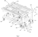
FIG. 2 is a schematic view of one embodiment of the transporter engaging device and the battery swapping transporter inFIG. 1 , both of which are in an engaged state. - In accordance with the concepts of the present invention, there is provided herein an embodiment of a transporter engaging device and a battery swapping transporter matched therewith.
- Referring to
FIGS. 1 and2 , the transporterengaging device 100 comprises: abracket body 110, a first guidingportion 120 disposed at a lower portion of thebracket body 110, and afirst positioning portion 130 disposed at an upper portion of thebracket body 110. Wherein, the first guidingportion 120 is used to provide a guiding function for an engaging action of a matched transporter, and thefirst positioning portion 130 is used for providing positioning of engagement with the matched transporter. The transporter engaging device achieves a guiding match with the matched battery swapping transporter through the first guiding portion, so that the battery swapping transporter moves relative to the transporter engaging device to the location to be positioned; accurate engagement between the two is achieved through the first positioning portion and the matched battery swapping transporter. This set of device has simple structure, small volume and capable of saving a certain floor space while realizing quick and convenient engagement, which is especially suitable for small places and sites with small amount of battery swapping. - Wherein, due to the fact that the matched battery swapping transporter is a vehicle structure, it has the moving features such as wheels and the like. Therefore, disposing the first guiding portion at the lower portion of the bracket body can effectively utilize the car bottom space of the battery swapping transporter, without adding extra floor space achieving the guiding function. Further, since the matched battery swapping transporter typically has a lifting element to facilitate replacement of the battery for car. Therefore, disposing the first positioning portion at the upper portion of the bracket body can effectively utilize the existing lifting structure of the battery swapping transporter to realize positioning of engagement with the first positioning portion, without adding extra dedicated structure while achieving accurate engagement, effectively improving the utilization of the existing designed element.
- Further, while only the first guiding portion and the first positioning portion are mentioned in the foregoing concept, and the specific structure thereof is not taught, the key of this concept is to effectively utilize the existing structure and the existing floor space of the battery swapping transporter matched therewith in combination with the disposing position of the two, and to achieve engagement with the battery swapping transporter while not adding structure and floor space as much as possible. With respect to the detailed configuration of the first guiding portion and the first positioning portion themselves, reference may be made to the design of a variety of mature guiding elements and positioning elements in the prior art, and they may be used herein to accomplish this concept.
- Of course, to better realize this concept, several specific implementations of the first guiding portion and the first positioning portion and their association with the bracket body are also provided hereinafter, as will be described one by one below.
- For example, the
bracket body 110 of the transporterengaging device 100 includes atop plate 111, abase 112, and abracket post 113 supported between thetop plate 111 and thebase 112; wherein the first guidingportion 120 is disposed on thebase 112, and thefirst positioning portion 130 is disposed on thetop plate 111. Such kind of frame type structure has comprehensive consideration for structural strength and manufacturing cost. - Optionally, the
bracket body 110 may also include aheight adjusting portion 140 disposed on thebase 112 for adjusting the height between thetop plate 111 and the mounting reference plane of thebracket body 110. The height adjusting function of the bracket body is thus realized, so that the bracket body can be applied to battery swapping transporters with different heights of the automobile body, improving the applicability of the device. Specifically, suchheight adjusting portion 140 may be afoundation bolt 141, and thebase 112 includes afirst bottom plate 112a connecting thebracket post 113 and asecond bottom plate 112b disposed apart from thefirst bottom plate 112a and is closer to the mounting reference plane; thefoundation bolt 141 is interposed between thefirst bottom plate 112a and thesecond bottom plate 112b and is used for adjusting the distance between thefirst bottom plate 112a and thesecond bottom plate 112b. The increase and decrease of the distance between thefirst bottom plate 112a and thesecond bottom plate 112b also directly affects the overall increase and decrease of the height of the bracket body, which is a specific implementation. - As another example, as one specific implementation, the first guiding
portion 120 includes a guidingfork 121 disposed toward the transporter engaging side, and the front end of the guidingfork 121 has a divergent guiding opening. At this time, the guided element on the matched transporter may be gradually guided to the desired location to be positioned after contacting with the divergent guiding opening in order to proceed with the next engagement action. - As another example, as one specific implementation, the
first positioning portion 130 includes apositioning pin 131 disposed at an upper portion of thebracket body 110. At this time, after the matched transporter has been moved to the desired location to be positioned, the element to be positioned thereon may be aligned with thepositioning pin 131 and fitted thereon to complete the entire engaging process. Optionally, at least two positioningpins 131 are disposed at both sides of the upper portion of thebracket body 110, respectively. Through multi-point positioning, a more stable engaging effect may be achieved. - Referring also to
FIGS. 1 and2 , a battery swapping transporter is also shown. Thebattery swapping transporter 200 comprises; a bearingportion 210 for bearing a battery to be replaced; a movingportion 220 which is disposed at the bottom of the bearingportion 210 and is used for driving the bearingportion 210 to move; asecond guiding portion 230 disposed at the lower portion of the bearingportion 210 and asecond positioning portion 240 disposed at the upper portion of the bearingportion 210. Wherein, thesecond guiding portion 230 is used to match with thefirst guiding portion 120 of thetransporter engaging device 100; and thesecond positioning portion 240 is used to match with thefirst positioning portion 130 of thetransporter engaging device 100. By disposing the guiding element and the positioning element matched with the transporter engaging device on the battery swapping transporter, rapid engagement of the two elements is effectively achieved. - As previously mentioned, since the matched battery swapping transporter is typically of a vehicle configuration, it has moving portions such as wheels by itself. Therefore, disposing the second guiding portion at the lower portion of the bearing portion can effectively utilize the residual car bottom space of the occupied portion that has been occupied by the moving portion below the bearing portion, without adding extra floor space while achieving the guiding function. Further, due to the fact that the bearing portion of the matched battery swapping transporter generally has a lifting function so as to realize the replacement of the battery for car. Therefore, disposing the second positioning portion at the upper portion of the bearing portion can effectively utilize the existing lifting function of the battery swapping transporter to realize positioning of engagement with the first positioning portion, without adding extra dedicated structure while achieving accurate engagement, effectively improving the utilization of the existing designed element.
- Further, while only the second guiding portion and the second positioning portion are mentioned in the foregoing concept, and the specific structure thereof is not taught, the key of this concept is to effectively utilize the existing structure and the existing floor space of the battery swapping transporter matched therewith in combination with the disposing position of the two, and to achieve engagement with the battery swapping transporter while not adding structure and floor space as much as possible. With respect to the detailed configuration of the second guiding portion and the second positioning portion themselves, reference may be made to the design of a variety of mature guiding elements and positioning elements in the prior art, and they may be used herein to accomplish this concept.
- Of course, to better realize this concept, several specific implementations of the second guiding portion and the second positioning portion and their association with the bearing portion are also provided hereinafter, as will be described one by one below.
- For example, the
second guiding portion 230 of thebattery swapping transporter 200 comprises a guidingshaft 231 extending in a vertical direction that matches with thefirst guiding portion 120 of thetransporter engaging device 100. Specifically, when the guidingshaft 231 is in contact with the divergent guiding opening of the guidingfork 121 of thefirst guiding portion 120, the guidingshaft 231 will be gradually moved to the desired position under the guide thereof. While when the guidingshaft 231 has been moved to the desired position, thebattery swapping transporter 200 integrated therewith will also move to the desired location to be positioned in order to proceed with the next engagement action. Optionally, thesecond guiding portion 230 further includes a guidingroller 232 coaxially disposed at the lower end of the guidingshaft 231, the guidingroller 232 rotatably matches with thefirst guiding portion 120 of thetransporter engaging device 100. In this arrangement, the registration of the guidingroller 232 with the guidingfork 121 is more stable. Therefore, the process of moving thebattery swapping transporter 200 to the desired location to be positioned will also be more stable. - As another example, as a specific implementation, the bearing
portion 210 is capable of lifting motion in the vertical direction; thesecond positioning portion 240 includes a positioningend plate 241 that protrudes by extending from the front portion of the bearingportion 210, apositioning hole 242 is disposed on the positioningend plate 241, and thepositioning hole 242 is capable of moving in the vertical direction and matching with thefirst positioning portion 130 of thetransporter engaging device 100. At this time, the positioning holes 242 on the positioningend plate 241 are staggered and aligned with the positioning pins 131 on the upper portion of thebracket body 110 by moving the bearingportion 210 upward after the battery swapping transporter has been moved to the desired location to be positioned; the bearingportion 210 is then moved downward so that thepositioning pin 131 fits into thepositioning hole 242, thereby enabling the entire engaging process of the battery swapping transporter and the transporter engaging device. Optionally, at least two positioningend plates 241 are disposed at both sides of the front portion of the bearingportion 210. Through multi-point positioning, a more stable engaging effect may be achieved. - Still further, in accordance with another aspect of the present concept, there is also provided an engaging method for implementing the engagement between the aforementioned
battery swapping transporter 200 andtransporter engaging device 100, which may be implemented not only by simply automatic controlling but also by manually operating of a worker. An implementation process of this is described in detail as follows. The engaging method comprises: guiding step S100, wherein thesecond guiding portion 230 of thebattery swapping transporter 200 is in contact with thefirst guiding portion 120 of thetransporter engaging device 100 and moves along thefirst guiding portion 120 to the location to be positioned; and positioning step S200, wherein thesecond positioning portion 240 of thebattery swapping transporter 200 is lifted to be staggered and aligned in the vertical direction with thefirst positioning portion 130 of thetransporter engaging device 100, and thesecond positioning portion 240 is lowered to engage with thefirst positioning portion 130. - Referring to
FIGS. 1 and2 , the engaging process of thebattery swapping transporter 200 and thetransporter engaging device 100 is set forth below in conjunction with an embodiment of the aforementioned method and apparatus. - First, the
bracket body 110 of thetransporter engaging device 100 is firstly fixed in place. For example, it is fixed before the battery pack storage platform exchange port, and the overall height of thebracket body 110 is adjusted to match the height of the battery swapping transporter by thefoundation bolts 141. The guidingfork 121 is then fixed at the side of thebracket body 110 facing the transporter by afoundation bolt 141, and is preferably fixed in an intermediate position to facilitate guiding adjustment. The guidingshaft 231, which is fixed at the bottom of the bearingportion 210 of thebattery swapping transporter 200, is then substantially aligned with the divergent guiding opening of the guidingfork 121 and thebattery swapping transporter 200 is driven in the direction A. When thebattery swapping transporter 200 moves, the direction of movement will be corrected with the assistance of the guidingroller 232 and the diverging guiding openings of the guidingfork 121 until thebattery swapping transporter 200 moves to the desired location to be positioned. Subsequently, thebattery swapping transporter 200 may be swung side-to-side in the direction B so that the positioning holes 242 thereon are aligned with the positioning pins 131 on thetransporter engaging device 100. Thereafter, the bearingportion 210 is moved downward so as to fit thepositioning pin 131 into thepositioning hole 242, thereby enabling the entire engaging process of the battery swapping transporter and the transporter engaging device. - The above examples mainly illustrate a transporter engaging device, a battery swapping transporter, and an engaging method. While only some of the embodiments of the present invention have been described, it will be appreciated by those of ordinary skill in the art that the present invention may be implemented in many other forms without departing from the scope of the invention as defined by the appended claims. Accordingly, the illustrated examples and embodiments are to be considered as illustrative and not restrictive, and the invention may compass various modifications and alternations without departing from the scope of the invention as defined by the appended claims.
Claims (9)
- A transporter engaging device (100), comprising:a bracket body (110) which includes a top plate (111), a base (112), and a bracket post (113) supported between the top plate (111) and the base (112); wherein a guiding portion (120) is disposed on the base (112), and a positioning portion (130) is disposed on the top plate (111);the guiding portion (120) disposed at a lower portion of the bracket body (110) and can provide guiding for an engaging action of the transporter; andthe positioning portion (130) disposed at an upper portion of the bracket body (110) and can be positioned in engagement with the transporter;wherein the guiding portion (120) includes a guiding fork (121) disposed toward a transporter engaging side, the guiding fork (121) having a divergent guiding opening at a front end; andwherein the positioning portion (130) comprises a positioning pin (131) disposed at the upper portion of the bracket body (110).
- The transporter engaging device (100) of claim 1, further comprising a height adjusting portion (140) disposed on the base (112) for adjusting a height between the top plate (111) and a mounting reference plane of the bracket body (110).
- The transporter engaging device (100) of claim 2, wherein the height adjusting portion (140) comprises a foundation bolt (141), and the base (112) comprises a first bottom plate (112a) connecting the bracket post (113), a second bottom plate (112b) disposed apart from the first bottom plate (112a) and is closer to the mounting reference plane; the foundation pin bolt (141) is interposed between the first bottom plate (112a) and the second bottom plate (112b), and is used for adjusting a distance between the first bottom plate (112a) and the second bottom plate (112b).
- The transporter engaging device (100) of claim 1, wherein at least two of the positioning pins (131) are disposed at two sides of the upper portion of the bracket body (110), respectively.
- A battery swapping transporter (200), comprising:a bearing portion (210) used for bearing a battery to be replaced;a moving portion (220) disposed at a bottom of the bearing portion (210) and used for driving the bearing portion (210) to move;a guiding portion (230) disposed at a lower portion of the bearing portion (210) and can match with a guiding portion (120) of a transporter engaging device (100); anda positioning portion (240) disposed at an upper portion of the bearing portion (210) and can match with a positioning portion (130) of the transporter engaging device (100);wherein the guiding portion (230) includes a guiding shaft (231) extending in a vertical direction, the guiding shaft (231) matching with the guiding portion (120) of the transporter engaging device (100).
- The battery swapping transporter (200) of claim 5, wherein the guiding portion (230) further comprises a guiding roller (232) coaxially disposed at the lower end of the guiding shaft (231), the guiding roller (232) rotatably matching with the guiding portion (120) of the transporter engaging device (100).
- The battery swapping transporter (200) according to claim 5 or 6, wherein the bearing portion (210) is capable of lifting motion in the vertical direction; the positioning portion (240) comprises a positioning end plate (241) that protrudes by extending from the front portion of the bearing portion (210), a positioning hole (242) is disposed on the positioning end plate (241), and the positioning hole (242) can move in the vertical direction and match with the positioning portion (130) of the transporter engaging device (100).
- The battery swapping transporter (200) according to claim 7, wherein at least two of the positioning end plates (241) are disposed at two sides of the front portion of the bearing portion (210), respectively.
- An engaging method between a battery swapping transporter (200) and a transporter engaging device (100) for the transporter engaging device (100) according to any of claims 1 to 4 and the battery swapping transporter (200) according to any of claims 5 to 8, comprising:a guiding step, wherein a guiding portion (230) of the battery swapping transporter (200) is in contact with a guiding portion (120) of the transporter engaging device (100) and moves to a location to be positioned along the guiding portion (120); anda positioning step, wherein a positioning portion (240) of the battery swapping transporter (200) is lifted to be staggered and aligned with a positioning portion (130) of the transporter engaging device (100) in a vertical direction, and the positioning portion (240) of the battery swapping transporter (200) is lowered to engage with the positioning portion (130) of the transporter engaging device (100).
Applications Claiming Priority (2)
| Application Number | Priority Date | Filing Date | Title |
|---|---|---|---|
| CN201710957845.3A CN108791226B (en) | 2017-10-16 | 2017-10-16 | Transporter docking device, battery exchange transporter and docking method |
| PCT/CN2018/075563 WO2019075964A1 (en) | 2017-10-16 | 2018-02-07 | Transporter docking device, power exchange transporter and and docking method |
Publications (3)
| Publication Number | Publication Date |
|---|---|
| EP3699043A1 EP3699043A1 (en) | 2020-08-26 |
| EP3699043A4 EP3699043A4 (en) | 2021-07-21 |
| EP3699043B1 true EP3699043B1 (en) | 2023-09-06 |
Family
ID=64094585
Family Applications (1)
| Application Number | Title | Priority Date | Filing Date |
|---|---|---|---|
| EP18867611.8A Active EP3699043B1 (en) | 2017-10-16 | 2018-02-07 | Transporter docking device, power exchange transporter and docking method |
Country Status (4)
| Country | Link |
|---|---|
| EP (1) | EP3699043B1 (en) |
| CN (1) | CN108791226B (en) |
| TW (1) | TWI806908B (en) |
| WO (1) | WO2019075964A1 (en) |
Families Citing this family (3)
| Publication number | Priority date | Publication date | Assignee | Title |
|---|---|---|---|---|
| CN109809131B (en) * | 2019-03-28 | 2024-04-26 | 中车长江车辆有限公司 | Cargo transferring, loading and unloading positioning method and device |
| TWI819351B (en) * | 2021-08-10 | 2023-10-21 | 迅得機械股份有限公司 | Internal conveying mechanism |
| GB2626160A (en) * | 2023-01-12 | 2024-07-17 | Continental Automotive Tech Gmbh | System suitable for facilitating battery swapping, and an apparatus and a swapping method in association thereto |
Family Cites Families (17)
| Publication number | Priority date | Publication date | Assignee | Title |
|---|---|---|---|---|
| US4450400A (en) * | 1981-12-04 | 1984-05-22 | Gwyn Marion V | Battery replacement system for electric vehicles |
| US4746258A (en) * | 1985-09-13 | 1988-05-24 | Litton Systems, Inc. | Floating table for article transport vehicle |
| US6272406B2 (en) * | 1998-03-09 | 2001-08-07 | Jervis B. Webb Company | Guidance system for an automated guided-vehicle |
| CN201136484Y (en) * | 2008-01-09 | 2008-10-22 | 北京电巴科技有限公司 | A positioning device for a vehicle battery replacement system |
| CN201417897Y (en) * | 2009-06-01 | 2010-03-03 | 江苏金华厦电气有限公司 | Carrier loader of middle-arranged switch cabinet |
| CN202029822U (en) * | 2010-12-16 | 2011-11-09 | 上海东裕电动车有限公司 | Battery replacing vehicle for electric vehicle |
| EP2537721B1 (en) * | 2011-06-20 | 2020-02-19 | Kabushiki Kaisha Toyota Jidoshokki | Locking apparatus for vehicle |
| CN202163415U (en) * | 2011-06-29 | 2012-03-14 | 新乡市新马车辆有限公司 | Device for replacing storage battery of electric vehicle |
| CN102992012B (en) * | 2011-09-15 | 2015-07-15 | 鸿富锦精密工业(深圳)有限公司 | Positioning mechanism |
| CN102935840B (en) * | 2012-11-19 | 2016-06-15 | 上汽通用五菱汽车股份有限公司 | A kind of assembly tool of new forms of energy car electrokinetic cell bag |
| CN103241111B (en) * | 2013-05-07 | 2016-01-06 | 卢国骥 | A kind of car bottom side is changed the battery-driven car of battery to interlock and is taken the device of battery |
| CN103303268B (en) * | 2013-06-09 | 2015-12-23 | 浙江瓿达科技有限公司 | Electronlmobil utilizes and changes the method that battery changed by electric dolly |
| CN205872015U (en) * | 2016-06-20 | 2017-01-11 | 蔚来汽车有限公司 | Exchange electric trolley |
| CN206254982U (en) * | 2016-11-17 | 2017-06-16 | 蔚来汽车有限公司 | Shuttle positioning mechanism |
| CN206395343U (en) * | 2016-12-06 | 2017-08-11 | 上海君屹工业自动化股份有限公司 | AGV trolley positioning mechanisms |
| CN107039844A (en) * | 2017-05-27 | 2017-08-11 | 厦门大学 | Towards the flexible docking device of intelligent vehicle recharging |
| CN207670384U (en) * | 2017-10-16 | 2018-07-31 | 蔚来汽车有限公司 | Transporter docking device and battery exchange transporter |
-
2017
- 2017-10-16 CN CN201710957845.3A patent/CN108791226B/en active Active
-
2018
- 2018-02-07 EP EP18867611.8A patent/EP3699043B1/en active Active
- 2018-02-07 WO PCT/CN2018/075563 patent/WO2019075964A1/en not_active Ceased
- 2018-10-15 TW TW107136240A patent/TWI806908B/en active
Also Published As
| Publication number | Publication date |
|---|---|
| WO2019075964A1 (en) | 2019-04-25 |
| EP3699043A1 (en) | 2020-08-26 |
| TWI806908B (en) | 2023-07-01 |
| CN108791226A (en) | 2018-11-13 |
| EP3699043A4 (en) | 2021-07-21 |
| CN108791226B (en) | 2023-03-10 |
| TW201917088A (en) | 2019-05-01 |
Similar Documents
| Publication | Publication Date | Title |
|---|---|---|
| EP3705361B1 (en) | Battery swapping transporting device | |
| EP3725606A1 (en) | Battery charging and swapping station | |
| CN215621509U (en) | swap station | |
| CN103264684B (en) | The battery disassembly and assembly mechanism of electronlmobil and the battery disassembly and assembly method of electronlmobil | |
| CN109501755B (en) | Automatic battery replacing platform and battery replacing station of electric automobile | |
| CN113291196B (en) | Battery swapping system for battery swapping stations | |
| CN112644328A (en) | AGV formula electric motor car trades electric system | |
| TWM581073U (en) | Battery charging and swapping station | |
| CN114132213B (en) | Battery swap control method for battery swap station | |
| CN102275573B (en) | Electric bus battery quick change system | |
| WO2019042131A1 (en) | Battery transfer device, system, and method | |
| CN204488761U (en) | A kind of side entering type electric automobile power battery automatic-exchanging system | |
| CN115285078B (en) | A battery swap station | |
| EP3699043A1 (en) | Transporter docking device, power exchange transporter and docking method | |
| TWM575802U (en) | Docking device and electric swapping transporter of transporters | |
| CN115520048A (en) | A heavy truck replacement station | |
| JP3182689B2 (en) | Automatic battery changer for unmanned vehicles | |
| CN104338883B (en) | Rotation of wheel forging press handling mould trolley | |
| CN218228951U (en) | Heavy-duty card battery replacement station | |
| CN114475342A (en) | Combined battery replacing robot | |
| CN217944956U (en) | Power exchange system for power exchange stations | |
| CN223302672U (en) | Parallel lateral type power exchange station | |
| CN112440812A (en) | Electric automobile trades electric installation | |
| CN117507929A (en) | Electric truck battery swapping system and battery swapping method | |
| CN110774247A (en) | Vehicle type switching device |
Legal Events
| Date | Code | Title | Description |
|---|---|---|---|
| STAA | Information on the status of an ep patent application or granted ep patent |
Free format text: STATUS: THE INTERNATIONAL PUBLICATION HAS BEEN MADE |
|
| PUAI | Public reference made under article 153(3) epc to a published international application that has entered the european phase |
Free format text: ORIGINAL CODE: 0009012 |
|
| STAA | Information on the status of an ep patent application or granted ep patent |
Free format text: STATUS: REQUEST FOR EXAMINATION WAS MADE |
|
| 17P | Request for examination filed |
Effective date: 20200518 |
|
| AK | Designated contracting states |
Kind code of ref document: A1 Designated state(s): AL AT BE BG CH CY CZ DE DK EE ES FI FR GB GR HR HU IE IS IT LI LT LU LV MC MK MT NL NO PL PT RO RS SE SI SK SM TR |
|
| AX | Request for extension of the european patent |
Extension state: BA ME |
|
| RAP1 | Party data changed (applicant data changed or rights of an application transferred) |
Owner name: NIO (ANHUI) HOLDING CO., LTD. |
|
| RIN1 | Information on inventor provided before grant (corrected) |
Inventor name: LI, NAN Inventor name: DING, XIKUN Inventor name: BENGTSSON, JAN Inventor name: TIAN, XIAOTAO Inventor name: MA, YONGYUE |
|
| DAV | Request for validation of the european patent (deleted) | ||
| DAX | Request for extension of the european patent (deleted) | ||
| A4 | Supplementary search report drawn up and despatched |
Effective date: 20210622 |
|
| RIC1 | Information provided on ipc code assigned before grant |
Ipc: B60S 5/06 20190101AFI20210616BHEP |
|
| GRAP | Despatch of communication of intention to grant a patent |
Free format text: ORIGINAL CODE: EPIDOSNIGR1 |
|
| STAA | Information on the status of an ep patent application or granted ep patent |
Free format text: STATUS: GRANT OF PATENT IS INTENDED |
|
| INTG | Intention to grant announced |
Effective date: 20230621 |
|
| GRAS | Grant fee paid |
Free format text: ORIGINAL CODE: EPIDOSNIGR3 |
|
| GRAA | (expected) grant |
Free format text: ORIGINAL CODE: 0009210 |
|
| STAA | Information on the status of an ep patent application or granted ep patent |
Free format text: STATUS: THE PATENT HAS BEEN GRANTED |
|
| AK | Designated contracting states |
Kind code of ref document: B1 Designated state(s): AL AT BE BG CH CY CZ DE DK EE ES FI FR GB GR HR HU IE IS IT LI LT LU LV MC MK MT NL NO PL PT RO RS SE SI SK SM TR |
|
| REG | Reference to a national code |
Ref country code: GB Ref legal event code: FG4D |
|
| REG | Reference to a national code |
Ref country code: CH Ref legal event code: EP |
|
| REG | Reference to a national code |
Ref country code: IE Ref legal event code: FG4D |
|
| REG | Reference to a national code |
Ref country code: DE Ref legal event code: R096 Ref document number: 602018057210 Country of ref document: DE |
|
| REG | Reference to a national code |
Ref country code: LT Ref legal event code: MG9D |
|
| REG | Reference to a national code |
Ref country code: NL Ref legal event code: MP Effective date: 20230906 |
|
| PG25 | Lapsed in a contracting state [announced via postgrant information from national office to epo] |
Ref country code: GR Free format text: LAPSE BECAUSE OF FAILURE TO SUBMIT A TRANSLATION OF THE DESCRIPTION OR TO PAY THE FEE WITHIN THE PRESCRIBED TIME-LIMIT Effective date: 20231207 |
|
| PG25 | Lapsed in a contracting state [announced via postgrant information from national office to epo] |
Ref country code: SE Free format text: LAPSE BECAUSE OF FAILURE TO SUBMIT A TRANSLATION OF THE DESCRIPTION OR TO PAY THE FEE WITHIN THE PRESCRIBED TIME-LIMIT Effective date: 20230906 Ref country code: RS Free format text: LAPSE BECAUSE OF FAILURE TO SUBMIT A TRANSLATION OF THE DESCRIPTION OR TO PAY THE FEE WITHIN THE PRESCRIBED TIME-LIMIT Effective date: 20230906 Ref country code: NO Free format text: LAPSE BECAUSE OF FAILURE TO SUBMIT A TRANSLATION OF THE DESCRIPTION OR TO PAY THE FEE WITHIN THE PRESCRIBED TIME-LIMIT Effective date: 20231206 Ref country code: LV Free format text: LAPSE BECAUSE OF FAILURE TO SUBMIT A TRANSLATION OF THE DESCRIPTION OR TO PAY THE FEE WITHIN THE PRESCRIBED TIME-LIMIT Effective date: 20230906 Ref country code: LT Free format text: LAPSE BECAUSE OF FAILURE TO SUBMIT A TRANSLATION OF THE DESCRIPTION OR TO PAY THE FEE WITHIN THE PRESCRIBED TIME-LIMIT Effective date: 20230906 Ref country code: HR Free format text: LAPSE BECAUSE OF FAILURE TO SUBMIT A TRANSLATION OF THE DESCRIPTION OR TO PAY THE FEE WITHIN THE PRESCRIBED TIME-LIMIT Effective date: 20230906 Ref country code: GR Free format text: LAPSE BECAUSE OF FAILURE TO SUBMIT A TRANSLATION OF THE DESCRIPTION OR TO PAY THE FEE WITHIN THE PRESCRIBED TIME-LIMIT Effective date: 20231207 Ref country code: FI Free format text: LAPSE BECAUSE OF FAILURE TO SUBMIT A TRANSLATION OF THE DESCRIPTION OR TO PAY THE FEE WITHIN THE PRESCRIBED TIME-LIMIT Effective date: 20230906 |
|
| REG | Reference to a national code |
Ref country code: AT Ref legal event code: MK05 Ref document number: 1608155 Country of ref document: AT Kind code of ref document: T Effective date: 20230906 |
|
| PG25 | Lapsed in a contracting state [announced via postgrant information from national office to epo] |
Ref country code: NL Free format text: LAPSE BECAUSE OF FAILURE TO SUBMIT A TRANSLATION OF THE DESCRIPTION OR TO PAY THE FEE WITHIN THE PRESCRIBED TIME-LIMIT Effective date: 20230906 |
|
| PG25 | Lapsed in a contracting state [announced via postgrant information from national office to epo] |
Ref country code: IS Free format text: LAPSE BECAUSE OF FAILURE TO SUBMIT A TRANSLATION OF THE DESCRIPTION OR TO PAY THE FEE WITHIN THE PRESCRIBED TIME-LIMIT Effective date: 20240106 |
|
| PG25 | Lapsed in a contracting state [announced via postgrant information from national office to epo] |
Ref country code: AT Free format text: LAPSE BECAUSE OF FAILURE TO SUBMIT A TRANSLATION OF THE DESCRIPTION OR TO PAY THE FEE WITHIN THE PRESCRIBED TIME-LIMIT Effective date: 20230906 |
|
| PG25 | Lapsed in a contracting state [announced via postgrant information from national office to epo] |
Ref country code: ES Free format text: LAPSE BECAUSE OF FAILURE TO SUBMIT A TRANSLATION OF THE DESCRIPTION OR TO PAY THE FEE WITHIN THE PRESCRIBED TIME-LIMIT Effective date: 20230906 |
|
| PG25 | Lapsed in a contracting state [announced via postgrant information from national office to epo] |
Ref country code: SM Free format text: LAPSE BECAUSE OF FAILURE TO SUBMIT A TRANSLATION OF THE DESCRIPTION OR TO PAY THE FEE WITHIN THE PRESCRIBED TIME-LIMIT Effective date: 20230906 Ref country code: RO Free format text: LAPSE BECAUSE OF FAILURE TO SUBMIT A TRANSLATION OF THE DESCRIPTION OR TO PAY THE FEE WITHIN THE PRESCRIBED TIME-LIMIT Effective date: 20230906 Ref country code: IS Free format text: LAPSE BECAUSE OF FAILURE TO SUBMIT A TRANSLATION OF THE DESCRIPTION OR TO PAY THE FEE WITHIN THE PRESCRIBED TIME-LIMIT Effective date: 20240106 Ref country code: ES Free format text: LAPSE BECAUSE OF FAILURE TO SUBMIT A TRANSLATION OF THE DESCRIPTION OR TO PAY THE FEE WITHIN THE PRESCRIBED TIME-LIMIT Effective date: 20230906 Ref country code: EE Free format text: LAPSE BECAUSE OF FAILURE TO SUBMIT A TRANSLATION OF THE DESCRIPTION OR TO PAY THE FEE WITHIN THE PRESCRIBED TIME-LIMIT Effective date: 20230906 Ref country code: CZ Free format text: LAPSE BECAUSE OF FAILURE TO SUBMIT A TRANSLATION OF THE DESCRIPTION OR TO PAY THE FEE WITHIN THE PRESCRIBED TIME-LIMIT Effective date: 20230906 Ref country code: AT Free format text: LAPSE BECAUSE OF FAILURE TO SUBMIT A TRANSLATION OF THE DESCRIPTION OR TO PAY THE FEE WITHIN THE PRESCRIBED TIME-LIMIT Effective date: 20230906 Ref country code: SK Free format text: LAPSE BECAUSE OF FAILURE TO SUBMIT A TRANSLATION OF THE DESCRIPTION OR TO PAY THE FEE WITHIN THE PRESCRIBED TIME-LIMIT Effective date: 20230906 Ref country code: PT Free format text: LAPSE BECAUSE OF FAILURE TO SUBMIT A TRANSLATION OF THE DESCRIPTION OR TO PAY THE FEE WITHIN THE PRESCRIBED TIME-LIMIT Effective date: 20240108 |
|
| PG25 | Lapsed in a contracting state [announced via postgrant information from national office to epo] |
Ref country code: PL Free format text: LAPSE BECAUSE OF FAILURE TO SUBMIT A TRANSLATION OF THE DESCRIPTION OR TO PAY THE FEE WITHIN THE PRESCRIBED TIME-LIMIT Effective date: 20230906 Ref country code: IT Free format text: LAPSE BECAUSE OF FAILURE TO SUBMIT A TRANSLATION OF THE DESCRIPTION OR TO PAY THE FEE WITHIN THE PRESCRIBED TIME-LIMIT Effective date: 20230906 |
|
| REG | Reference to a national code |
Ref country code: DE Ref legal event code: R097 Ref document number: 602018057210 Country of ref document: DE |
|
| PG25 | Lapsed in a contracting state [announced via postgrant information from national office to epo] |
Ref country code: DK Free format text: LAPSE BECAUSE OF FAILURE TO SUBMIT A TRANSLATION OF THE DESCRIPTION OR TO PAY THE FEE WITHIN THE PRESCRIBED TIME-LIMIT Effective date: 20230906 |
|
| PLBE | No opposition filed within time limit |
Free format text: ORIGINAL CODE: 0009261 |
|
| STAA | Information on the status of an ep patent application or granted ep patent |
Free format text: STATUS: NO OPPOSITION FILED WITHIN TIME LIMIT |
|
| PG25 | Lapsed in a contracting state [announced via postgrant information from national office to epo] |
Ref country code: DK Free format text: LAPSE BECAUSE OF FAILURE TO SUBMIT A TRANSLATION OF THE DESCRIPTION OR TO PAY THE FEE WITHIN THE PRESCRIBED TIME-LIMIT Effective date: 20230906 Ref country code: SI Free format text: LAPSE BECAUSE OF FAILURE TO SUBMIT A TRANSLATION OF THE DESCRIPTION OR TO PAY THE FEE WITHIN THE PRESCRIBED TIME-LIMIT Effective date: 20230906 |
|
| 26N | No opposition filed |
Effective date: 20240607 |
|
| PG25 | Lapsed in a contracting state [announced via postgrant information from national office to epo] |
Ref country code: MC Free format text: LAPSE BECAUSE OF FAILURE TO SUBMIT A TRANSLATION OF THE DESCRIPTION OR TO PAY THE FEE WITHIN THE PRESCRIBED TIME-LIMIT Effective date: 20230906 |
|
| REG | Reference to a national code |
Ref country code: CH Ref legal event code: PL |
|
| PG25 | Lapsed in a contracting state [announced via postgrant information from national office to epo] |
Ref country code: LU Free format text: LAPSE BECAUSE OF NON-PAYMENT OF DUE FEES Effective date: 20240207 |
|
| PG25 | Lapsed in a contracting state [announced via postgrant information from national office to epo] |
Ref country code: CH Free format text: LAPSE BECAUSE OF NON-PAYMENT OF DUE FEES Effective date: 20240229 |
|
| PG25 | Lapsed in a contracting state [announced via postgrant information from national office to epo] |
Ref country code: LU Free format text: LAPSE BECAUSE OF NON-PAYMENT OF DUE FEES Effective date: 20240207 Ref country code: CH Free format text: LAPSE BECAUSE OF NON-PAYMENT OF DUE FEES Effective date: 20240229 |
|
| PG25 | Lapsed in a contracting state [announced via postgrant information from national office to epo] |
Ref country code: BG Free format text: LAPSE BECAUSE OF FAILURE TO SUBMIT A TRANSLATION OF THE DESCRIPTION OR TO PAY THE FEE WITHIN THE PRESCRIBED TIME-LIMIT Effective date: 20230906 |
|
| PG25 | Lapsed in a contracting state [announced via postgrant information from national office to epo] |
Ref country code: BG Free format text: LAPSE BECAUSE OF FAILURE TO SUBMIT A TRANSLATION OF THE DESCRIPTION OR TO PAY THE FEE WITHIN THE PRESCRIBED TIME-LIMIT Effective date: 20230906 |
|
| REG | Reference to a national code |
Ref country code: BE Ref legal event code: MM Effective date: 20240229 |
|
| PG25 | Lapsed in a contracting state [announced via postgrant information from national office to epo] |
Ref country code: BE Free format text: LAPSE BECAUSE OF NON-PAYMENT OF DUE FEES Effective date: 20240229 |
|
| PG25 | Lapsed in a contracting state [announced via postgrant information from national office to epo] |
Ref country code: IE Free format text: LAPSE BECAUSE OF NON-PAYMENT OF DUE FEES Effective date: 20240207 |
|
| PG25 | Lapsed in a contracting state [announced via postgrant information from national office to epo] |
Ref country code: IE Free format text: LAPSE BECAUSE OF NON-PAYMENT OF DUE FEES Effective date: 20240207 Ref country code: BE Free format text: LAPSE BECAUSE OF NON-PAYMENT OF DUE FEES Effective date: 20240229 |
|
| PG25 | Lapsed in a contracting state [announced via postgrant information from national office to epo] |
Ref country code: CY Free format text: LAPSE BECAUSE OF FAILURE TO SUBMIT A TRANSLATION OF THE DESCRIPTION OR TO PAY THE FEE WITHIN THE PRESCRIBED TIME-LIMIT; INVALID AB INITIO Effective date: 20180207 |
|
| PG25 | Lapsed in a contracting state [announced via postgrant information from national office to epo] |
Ref country code: HU Free format text: LAPSE BECAUSE OF FAILURE TO SUBMIT A TRANSLATION OF THE DESCRIPTION OR TO PAY THE FEE WITHIN THE PRESCRIBED TIME-LIMIT; INVALID AB INITIO Effective date: 20180207 |
|
| PG25 | Lapsed in a contracting state [announced via postgrant information from national office to epo] |
Ref country code: TR Free format text: LAPSE BECAUSE OF FAILURE TO SUBMIT A TRANSLATION OF THE DESCRIPTION OR TO PAY THE FEE WITHIN THE PRESCRIBED TIME-LIMIT Effective date: 20230906 |
|
| PGFP | Annual fee paid to national office [announced via postgrant information from national office to epo] |
Ref country code: GB Payment date: 20260220 Year of fee payment: 9 |
|
| PGFP | Annual fee paid to national office [announced via postgrant information from national office to epo] |
Ref country code: DE Payment date: 20260218 Year of fee payment: 9 |
|
| PGFP | Annual fee paid to national office [announced via postgrant information from national office to epo] |
Ref country code: FR Payment date: 20260218 Year of fee payment: 9 |