EP3699000A1 - Suspension operating system and suspension operation terminal - Google Patents
Suspension operating system and suspension operation terminal Download PDFInfo
- Publication number
- EP3699000A1 EP3699000A1 EP18868809.7A EP18868809A EP3699000A1 EP 3699000 A1 EP3699000 A1 EP 3699000A1 EP 18868809 A EP18868809 A EP 18868809A EP 3699000 A1 EP3699000 A1 EP 3699000A1
- Authority
- EP
- European Patent Office
- Prior art keywords
- suspension
- actuator
- wheel
- operation terminal
- control device
- Prior art date
- Legal status (The legal status is an assumption and is not a legal conclusion. Google has not performed a legal analysis and makes no representation as to the accuracy of the status listed.)
- Granted
Links
Images







Classifications
-
- B—PERFORMING OPERATIONS; TRANSPORTING
- B62—LAND VEHICLES FOR TRAVELLING OTHERWISE THAN ON RAILS
- B62D—MOTOR VEHICLES; TRAILERS
- B62D7/00—Steering linkage; Stub axles or their mountings
- B62D7/20—Links, e.g. track rods
-
- B—PERFORMING OPERATIONS; TRANSPORTING
- B60—VEHICLES IN GENERAL
- B60G—VEHICLE SUSPENSION ARRANGEMENTS
- B60G17/00—Resilient suspensions having means for adjusting the spring or vibration-damper characteristics, for regulating the distance between a supporting surface and a sprung part of vehicle or for locking suspension during use to meet varying vehicular or surface conditions, e.g. due to speed or load
- B60G17/015—Resilient suspensions having means for adjusting the spring or vibration-damper characteristics, for regulating the distance between a supporting surface and a sprung part of vehicle or for locking suspension during use to meet varying vehicular or surface conditions, e.g. due to speed or load the regulating means comprising electric or electronic elements
-
- B—PERFORMING OPERATIONS; TRANSPORTING
- B60—VEHICLES IN GENERAL
- B60G—VEHICLE SUSPENSION ARRANGEMENTS
- B60G3/00—Resilient suspensions for a single wheel
- B60G3/18—Resilient suspensions for a single wheel with two or more pivoted arms, e.g. parallelogram
-
- B—PERFORMING OPERATIONS; TRANSPORTING
- B60—VEHICLES IN GENERAL
- B60G—VEHICLE SUSPENSION ARRANGEMENTS
- B60G3/00—Resilient suspensions for a single wheel
- B60G3/18—Resilient suspensions for a single wheel with two or more pivoted arms, e.g. parallelogram
- B60G3/20—Resilient suspensions for a single wheel with two or more pivoted arms, e.g. parallelogram all arms being rigid
-
- B—PERFORMING OPERATIONS; TRANSPORTING
- B60—VEHICLES IN GENERAL
- B60G—VEHICLE SUSPENSION ARRANGEMENTS
- B60G7/00—Pivoted suspension arms; Accessories thereof
- B60G7/001—Suspension arms, e.g. constructional features
- B60G7/003—Suspension arms, e.g. constructional features of adjustable length
-
- B—PERFORMING OPERATIONS; TRANSPORTING
- B60—VEHICLES IN GENERAL
- B60G—VEHICLE SUSPENSION ARRANGEMENTS
- B60G7/00—Pivoted suspension arms; Accessories thereof
- B60G7/005—Ball joints
-
- B—PERFORMING OPERATIONS; TRANSPORTING
- B60—VEHICLES IN GENERAL
- B60G—VEHICLE SUSPENSION ARRANGEMENTS
- B60G7/00—Pivoted suspension arms; Accessories thereof
- B60G7/006—Attaching arms to sprung or unsprung part of vehicle, characterised by comprising attachment means controlled by an external actuator, e.g. a fluid or electrical motor
-
- B—PERFORMING OPERATIONS; TRANSPORTING
- B60—VEHICLES IN GENERAL
- B60R—VEHICLES, VEHICLE FITTINGS, OR VEHICLE PARTS, NOT OTHERWISE PROVIDED FOR
- B60R16/00—Electric or fluid circuits specially adapted for vehicles and not otherwise provided for; Arrangement of elements of electric or fluid circuits specially adapted for vehicles and not otherwise provided for
- B60R16/02—Electric or fluid circuits specially adapted for vehicles and not otherwise provided for; Arrangement of elements of electric or fluid circuits specially adapted for vehicles and not otherwise provided for electric constitutive elements
-
- B—PERFORMING OPERATIONS; TRANSPORTING
- B62—LAND VEHICLES FOR TRAVELLING OTHERWISE THAN ON RAILS
- B62D—MOTOR VEHICLES; TRAILERS
- B62D17/00—Means on vehicles for adjusting camber, castor, or toe-in
-
- B—PERFORMING OPERATIONS; TRANSPORTING
- B62—LAND VEHICLES FOR TRAVELLING OTHERWISE THAN ON RAILS
- B62D—MOTOR VEHICLES; TRAILERS
- B62D7/00—Steering linkage; Stub axles or their mountings
- B62D7/06—Steering linkage; Stub axles or their mountings for individually-pivoted wheels, e.g. on king-pins
- B62D7/14—Steering linkage; Stub axles or their mountings for individually-pivoted wheels, e.g. on king-pins the pivotal axes being situated in more than one plane transverse to the longitudinal centre line of the vehicle, e.g. all-wheel steering
- B62D7/146—Steering linkage; Stub axles or their mountings for individually-pivoted wheels, e.g. on king-pins the pivotal axes being situated in more than one plane transverse to the longitudinal centre line of the vehicle, e.g. all-wheel steering characterised by comprising means for steering by acting on the suspension system, e.g. on the mountings of the suspension arms
-
- F—MECHANICAL ENGINEERING; LIGHTING; HEATING; WEAPONS; BLASTING
- F16—ENGINEERING ELEMENTS AND UNITS; GENERAL MEASURES FOR PRODUCING AND MAINTAINING EFFECTIVE FUNCTIONING OF MACHINES OR INSTALLATIONS; THERMAL INSULATION IN GENERAL
- F16C—SHAFTS; FLEXIBLE SHAFTS; ELEMENTS OR CRANKSHAFT MECHANISMS; ROTARY BODIES OTHER THAN GEARING ELEMENTS; BEARINGS
- F16C11/00—Pivots; Pivotal connections
- F16C11/04—Pivotal connections
- F16C11/06—Ball-joints; Other joints having more than one degree of angular freedom, i.e. universal joints
- F16C11/0619—Ball-joints; Other joints having more than one degree of angular freedom, i.e. universal joints the female part comprising a blind socket receiving the male part
- F16C11/0623—Construction or details of the socket member
- F16C11/0647—Special features relating to adjustment for wear or play; Wear indicators
-
- F—MECHANICAL ENGINEERING; LIGHTING; HEATING; WEAPONS; BLASTING
- F16—ENGINEERING ELEMENTS AND UNITS; GENERAL MEASURES FOR PRODUCING AND MAINTAINING EFFECTIVE FUNCTIONING OF MACHINES OR INSTALLATIONS; THERMAL INSULATION IN GENERAL
- F16C—SHAFTS; FLEXIBLE SHAFTS; ELEMENTS OR CRANKSHAFT MECHANISMS; ROTARY BODIES OTHER THAN GEARING ELEMENTS; BEARINGS
- F16C11/00—Pivots; Pivotal connections
- F16C11/04—Pivotal connections
- F16C11/06—Ball-joints; Other joints having more than one degree of angular freedom, i.e. universal joints
- F16C11/0685—Manufacture of ball-joints and parts thereof, e.g. assembly of ball-joints
-
- G—PHYSICS
- G06—COMPUTING OR CALCULATING; COUNTING
- G06F—ELECTRIC DIGITAL DATA PROCESSING
- G06F3/00—Input arrangements for transferring data to be processed into a form capable of being handled by the computer; Output arrangements for transferring data from processing unit to output unit, e.g. interface arrangements
- G06F3/01—Input arrangements or combined input and output arrangements for interaction between user and computer
- G06F3/048—Interaction techniques based on graphical user interfaces [GUI]
- G06F3/0484—Interaction techniques based on graphical user interfaces [GUI] for the control of specific functions or operations, e.g. selecting or manipulating an object, an image or a displayed text element, setting a parameter value or selecting a range
-
- B—PERFORMING OPERATIONS; TRANSPORTING
- B60—VEHICLES IN GENERAL
- B60G—VEHICLE SUSPENSION ARRANGEMENTS
- B60G2200/00—Indexing codes relating to suspension types
- B60G2200/10—Independent suspensions
- B60G2200/18—Multilink suspensions, e.g. elastokinematic arrangements
-
- B—PERFORMING OPERATIONS; TRANSPORTING
- B60—VEHICLES IN GENERAL
- B60G—VEHICLE SUSPENSION ARRANGEMENTS
- B60G2200/00—Indexing codes relating to suspension types
- B60G2200/10—Independent suspensions
- B60G2200/18—Multilink suspensions, e.g. elastokinematic arrangements
- B60G2200/184—Assymetric arrangements
-
- B—PERFORMING OPERATIONS; TRANSPORTING
- B60—VEHICLES IN GENERAL
- B60G—VEHICLE SUSPENSION ARRANGEMENTS
- B60G2200/00—Indexing codes relating to suspension types
- B60G2200/40—Indexing codes relating to the wheels in the suspensions
- B60G2200/44—Indexing codes relating to the wheels in the suspensions steerable
-
- B—PERFORMING OPERATIONS; TRANSPORTING
- B60—VEHICLES IN GENERAL
- B60G—VEHICLE SUSPENSION ARRANGEMENTS
- B60G2200/00—Indexing codes relating to suspension types
- B60G2200/40—Indexing codes relating to the wheels in the suspensions
- B60G2200/46—Indexing codes relating to the wheels in the suspensions camber angle
-
- B—PERFORMING OPERATIONS; TRANSPORTING
- B60—VEHICLES IN GENERAL
- B60G—VEHICLE SUSPENSION ARRANGEMENTS
- B60G2200/00—Indexing codes relating to suspension types
- B60G2200/40—Indexing codes relating to the wheels in the suspensions
- B60G2200/462—Toe-in/out
-
- B—PERFORMING OPERATIONS; TRANSPORTING
- B60—VEHICLES IN GENERAL
- B60G—VEHICLE SUSPENSION ARRANGEMENTS
- B60G2202/00—Indexing codes relating to the type of spring, damper or actuator
- B60G2202/40—Type of actuator
- B60G2202/42—Electric actuator
-
- B—PERFORMING OPERATIONS; TRANSPORTING
- B60—VEHICLES IN GENERAL
- B60G—VEHICLE SUSPENSION ARRANGEMENTS
- B60G2204/00—Indexing codes related to suspensions per se or to auxiliary parts
- B60G2204/40—Auxiliary suspension parts; Adjustment of suspensions
- B60G2204/416—Ball or spherical joints
-
- B—PERFORMING OPERATIONS; TRANSPORTING
- B60—VEHICLES IN GENERAL
- B60G—VEHICLE SUSPENSION ARRANGEMENTS
- B60G2400/00—Indexing codes relating to detected, measured or calculated conditions or factors
- B60G2400/05—Attitude
- B60G2400/051—Angle
- B60G2400/0514—Wheel angle detection
- B60G2400/05142—Wheel camber
-
- B—PERFORMING OPERATIONS; TRANSPORTING
- B60—VEHICLES IN GENERAL
- B60G—VEHICLE SUSPENSION ARRANGEMENTS
- B60G2400/00—Indexing codes relating to detected, measured or calculated conditions or factors
- B60G2400/05—Attitude
- B60G2400/051—Angle
- B60G2400/0514—Wheel angle detection
- B60G2400/05144—Wheel toe
-
- B—PERFORMING OPERATIONS; TRANSPORTING
- B60—VEHICLES IN GENERAL
- B60G—VEHICLE SUSPENSION ARRANGEMENTS
- B60G2600/00—Indexing codes relating to particular elements, systems or processes used on suspension systems or suspension control systems
- B60G2600/11—Feedforward signal
-
- B—PERFORMING OPERATIONS; TRANSPORTING
- B60—VEHICLES IN GENERAL
- B60G—VEHICLE SUSPENSION ARRANGEMENTS
- B60G2600/00—Indexing codes relating to particular elements, systems or processes used on suspension systems or suspension control systems
- B60G2600/20—Manual control or setting means
- B60G2600/202—Manual control or setting means using a remote, e.g. cordless, transmitter or receiver unit
Definitions
- the present invention relates to a suspension operation system and a suspension operation terminal.
- a vehicle has a suspension provided between its body and a wheel.
- the suspension is a device that makes vibrations due to fluctuation of a road surface less likely to be transmitted to the vehicle body, and that positions the wheel.
- a multi-link suspension is known as one of suspension types.
- Patent Literature 1 describes an example of the multi-link suspension.
- Patent Literature 2 describes a work vehicle operation system that performs remote control on a vehicle by using a portable information terminal such as a smartphone and a tablet terminal.
- Patent Literature 2 does not describe suspension operation.
- the present invention has been made in view of the above, and aims to provide a suspension operation system and a suspension operation terminal that can easily operate a relative posture of the wheel with respect to the vehicle body.
- a suspension operation system includes: a suspension that includes a plurality of links supporting a wheel, at least one or more of the links having an actuator increasing or decreasing a length of the actuator in an axial direction; a control device that supplies a drive signal to the actuator to control operation of the suspension; and a suspension operation terminal that operates the suspension.
- the suspension operation terminal includes: a detector that detects operation input information to the suspension operation terminal; and a communicator that transmits information about a target posture of the wheel, the information being based on the operation input information, to the control device as an operation command.
- the control device includes: a first calculator that calculates the length of the actuator on the basis of the operation command; and a drive circuit that produces the drive signal on the basis of information from the first calculator.
- an operator can control the suspension including the plurality of extension-retraction links by operating the suspension operation terminal. Consequently, the degree of freedom in operating the suspension can be more increased than the conventional steering wheels.
- the suspension operation system can easily control the posture of the wheel by operating the suspension including the plurality of extension-retraction links.
- the suspension operation terminal includes a second calculator that calculates the operation command on the basis of the operation input information.
- the operation command includes information about at least one of a toe angle or a camber angle of the wheel. This makes it possible to control the toe angle and the camber angle of the wheel by the operation of the suspension operation terminal, thereby allowing an increased degree of freedom in operating the posture of the wheel.
- the suspension operation terminal further includes a display that displays an image.
- the detector includes a touch panel that detects touch input to a detection surface.
- the second calculator calculates the operation command by associating operation input information from the touch panel provided by slide operation performed on an operation indication body displayed on the detection surface with the camber angle of the wheel. Accordingly, the operator can control the camber angle of the wheel by operating the touch panel. The operator can determine whether the camber angle of the wheel is operated by performing the slide operation on the displayed operation indication body. Consequently, the suspension operation system can easily operate the camber angle of the wheel.
- the vehicle using the suspension operation system can adjust the motion performance of the vehicle by controlling the camber angles of the wheels in accordance with running conditions and running environments.
- the detector includes a sensor that detects rotation around a direction orthogonal to a detection surface of the suspension operation terminal, the direction serving as a rotation center axis.
- the second calculator calculates the operation command by associating a rotation angle of the suspension operation terminal, the rotation angle being obtained from the sensor, with the toe angle of the wheel. Accordingly, the operator can control the toe angle of the wheel by performing the rotation operation on the operation terminal.
- the suspension operation system associates the rotation operation of the suspension operation terminal with the toe angle of the wheel in the same manner as the operation of the conventional steering wheel, thereby making it possible to easily control the toe angle of the wheel.
- the communicator wirelessly transmits the operation command to the control device.
- the suspension operation terminal can be stored at a location where the suspension operation terminal does not interfere with occupants when the suspension operation terminal is not operated, such as a case where the vehicle is in an automatic drive mode, which improves comfortableness.
- a suspension operation terminal includes: a detector that detects operation input information for operating a suspension including a plurality of links supporting a wheel; and a communicator that wirelessly transmits information about a target posture of the wheel, the information being calculated on the basis of the operation input information, to a control device as an operation command.
- the suspension operation terminal operates a posture of the wheel by operating an actuator to increase or decrease a length of the actuator in an axial direction on the basis of the operation command, the actuator being included in at least one or more of the links.
- the operator can control the suspension including the plurality of extension-retraction links by operating the suspension operation terminal. Consequently, the degree of freedom in operating the suspension can be more increased than the conventional steering wheels.
- Operating the suspension including the plurality of links with the operation terminal makes it possible to easily control the posture of the wheel.
- the suspension operation terminal further includes: a calculator that calculates the operation command on the basis of the operation input information; and a display that displays an image.
- the detector includes a touch panel that detects touch input to a detection surface.
- the display displays an operation indication body on the detection surface, the operation indication body being associated with a camber angle of the wheel.
- the calculator calculates the operation command by associating operation input information from the touch panel provided by slide operation performed on the operation indication body with the camber angle of the wheel. Accordingly, the operator can control the camber angle of the wheel by operating the touch panel. The operator can determine whether the camber angle of the wheel is operated by performing the slide operation on the displayed operation indication body. Consequently, the suspension operation terminal can easily operate the camber angle of the wheel.
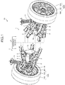
- FIG. 1 is a perspective view of suspensions of a suspension operation system in the embodiment.
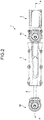
- FIG. 2 is a plan view of an extension-retraction link of the suspension operation system according to the embodiment.
- FIG. 3 is a cross-sectional view taken along A-A in FIG. 2 .
- FIG. 4 is a cross-sectional view of a second universal joint.
- a vehicle 10 in the embodiment includes wheels 102, hub units 101, vehicle body side members 18, hub carriers 19, suspensions 1, and a control device 9.
- the vehicle 10 includes four wheels 102, each of which includes the hub unit 101.
- the hub unit 101 has, for example, a hub bearing, two motors, and a speed changer, built-in.
- the hub unit 101 rotatably supports the wheel 102 and drives the wheel 102.
- the vehicle body side member 18 is fixed to the vehicle body.
- the hub carrier 19 is a member fixed to the hub unit 101.
- the hub carrier 19 is also called a knuckle.
- the suspension 1 is a device that connects the vehicle body (chassis) of the vehicle 10 and the hub unit 101.
- the suspension 1 is a multi-link suspension. As illustrated in FIG. 1 , the suspension 1 includes a shock absorber 11 and five extension-retraction links 2 for each wheel 102.
- the shock absorber 11 is a device that reduces shock transmitted to the vehicle body from a road surface during vehicle running. One end of the shock absorber 11 is fixed to the vehicle body. The other end of the shock absorber 11 is fixed to the hub carrier 19. The shock absorber 11 can extend and retract in an upper-lower direction.
- the extension-retraction link 2 connects the vehicle body side member 18 and the hub carrier 19. As illustrated in FIG. 1 , two extension-retraction links 2 are arranged on an upper side of the rotation axis of the wheel 102. Three extension-retraction links 2 are arranged on a lower side of the rotation axis of the wheel 102. As illustrated in FIG. 2 , the extension-retraction link 2 includes a stationary shaft 3, a movable shaft 4, a first universal joint 6a, a second universal joint 6b, and an actuator 5.
- the stationary shaft 3 is connected to the vehicle body side member 18 (refer to FIG. 1 ) with the first universal joint 6a interposed therebetween.
- the stationary shaft 3 has a tubular shape.
- the stationary shaft 3 includes a first member 31 and a second member 32.
- the first member 31 and the second member 32 are connected to each other with fastener members.
- the first universal joint 6a is attached to the first member 31.
- the movable shaft 4 is connected to the hub carrier 19 (refer to FIG. 1 ) with the second universal joint 6b interposed therebetween.
- the movable shaft 4 is a hollow member having an internal space 40. Part of the movable shaft 4 is located inside the stationary shaft 3.
- the movable shaft 4 can slide with respect to the stationary shaft 3.
- the slidable length of the movable shaft 4 is limited by a stopper 45 provided to the movable shaft 4.
- the stopper 45 is disposed in a groove 315 provided on an inner circumferential surface of the first member 31. When the stopper 45 reaches the end of the groove 315, the stopper 45 is in contact with the first member 31, thereby stopping the movable shaft 4. This prevents the movable shaft 4 from dropping off from the stationary shaft 3.
- the first universal joint 6a connects the stationary shaft 3 to the vehicle body side member 18 (refer to FIG. 1 ) such that the stationary shaft 3 can rotate and swing with respect to the vehicle body side member 18.
- the second universal joint 6b connects the movable shaft 4 to the hub carrier 19 (refer to FIG. 1 ) such that the movable shaft 4 can rotate and swing with respect to the hub carrier 19.
- the rotation means rotation around a straight line L1b (refer to FIG. 4 ) serving as the rotation center, while the swing means movement by which an angle ⁇ made between the straight line L1b and a straight line L2b changes.
- the straight line L1b is a straight line passing through the gravity center of each cross-sectional surface when an arm 61, which is described later, is cut with a plane orthogonal to the longitudinal direction of the arm 61.
- the straight line L2b is orthogonal to a circle formed by an outer shape of an external bush 63, which is described later, and passes through the center of the circle.
- An intersection Mb (refer to FIG. 14 ) of the straight lines L1b and L2b is the center of an arm convex surface 617p having a spherical surface shape, which is described later.
- the first universal joint 6a and the second universal joint 6b have the same structure.
- the second universal joint 6b is described as an example. The description of the second universal joint 6b can also be applied to that of the first universal joint 6a.
- the second universal joint 6b includes a housing 60, the arm 61, the external bush 63, an internal bush 65, elastic members 67, and a supporting member 69.
- the housing 60 is formed integrally with the end portion of the movable shaft 4.
- the housing 60 has a tubular shape.
- the housing 60 of the first universal joint 6a is formed integrally with the first member 31.
- the arm 61 is a member connected to the hub carrier 19 (refer to FIG. 1 ).
- the arm 61 is made of metal.
- the metal used for the arm 61 is steel, for example.
- Part of the arm 61 is located inside the housing 60.
- the arm 61 includes a fastening portion 611, a flange portion 613, an intermediate portion 615, and a sliding portion 617.
- the fastening portion 611 and the flange portion 613 are located outside the housing 60.
- the fastening portion 611 is a columnar member having a thread on its outer circumferential surface.
- the flange portion 613 is a member that is located on the housing 60 side of the fastening portion 611 and has a substantially conical shape in which the diameter of the flange portion 613 increases toward the housing 60.
- the intermediate portion 615 is a member that extends toward the housing 60 side from the flange portion 613 and has a substantially columnar shape.
- the intermediate portion 615 has two parallel flat surfaces on its outer circumferential surface.
- the sliding portion 617 is a member that is located on the housing 60 side of the intermediate portion 615 and has a substantially hemispherical shape.
- the sliding portion 617 includes the arm convex surface 617p, an arm concave surface 617q, and an arm end surface 617e.
- the arm convex surface 617p is the external surface of the sliding portion 617 and has a spherical surface shape.
- the arm concave surface 617q is the internal surface of the sliding portion 617 and has a spherical surface shape.
- the center of the arm concave surface 617q is the same as the center of the arm convex surface 617p.
- the arm end surface 617e is the end surface of the sliding portion 617 that connects the arm convex surface 617p and the arm concave surface 617q. Part of the arm end surface 617e is formed in a conical surface shape.
- the external bush 63 is an annular member located between the inner circumferential surface of the housing 60 and the arm 61.
- the external bush 63 is formed of metal.
- the metal used for the external bush 63 is brass, for example.
- the external bush 63 is press-fitted into the housing 60.
- the external bush 63 includes a bush concave surface 63q serving as its inner circumferential surface.
- the bush concave surface 63q has a spherical surface shape and is in contact with the arm convex surface 617p.
- the center and the radius of the bush concave surface 63q are the same as those of the arm convex surface 617p.
- the internal bush 65 is located inside the sliding portion 617 of the arm 61.
- the internal bush 65 is located on the opposite side of the external bush 63 with respect to the sliding portion 617.
- the internal bush 65 is formed of metal.
- the metal used for the internal bush 65 is brass, for example.
- the internal bush 65 includes a head portion 651 and a body portion 653.
- the head portion 651 has a substantially hemispherical shape and a bush convex surface 651p.
- the bush convex surface 651p is a spherical surface and in contact with the arm concave surface 617q.
- the sliding portion 617 is sandwiched between the bush convex surface 651p of the internal bush 65 and the bush concave surface 63q of the external bush 63.
- the center and the radius of the bush convex surface 651p are the same as those of the arm concave surface 617q.
- the body portion 653 is a substantially cylindrical member extending from the head portion 651 toward the opposite side of the bush convex surface 651p.
- the supporting member 69 supports the internal bush 65. As illustrated in FIG. 4 , the supporting member 69 is attached inside the housing 60.
- the supporting member 69 is formed of metal.
- the metal used for the supporting member 69 is steel, for example.
- the supporting member 69 includes a male screw 691, a first recess 693, and a second recess 695.
- the male screw 691 engages with a female screw 601 provided to the housing 60.
- the first recess 693 is a dent that opens toward the internal bush 65 and has a truncated cone shape.
- the bottom surface of the first recess 693 is a plane orthogonal to the extending direction of the body portion 653 of the internal bush 65.
- the second recess 695 is a dent that is provided on the bottom surface of the first recess 693 and has a columnar shape.
- the body portion 653 is fitted in the second recess 695 and guided by the inner circumferential surface of the second recess 695.
- the elastic members 67 are located between the internal bush 65 and the supporting member 69 and press the internal bush 65 toward the arm 61.
- the elastic member 67 is a disc spring, for example.
- Two elastic members 67 are arranged overlapping with each other between the body portion 653 and the bottom surface of the second recess 695.
- the inside of the housing 60 is filled with lubricant.
- the lubricant is grease, for example.
- the sliding portion 617 of the arm 61 can move along the external bush 63 and the internal bush 65. Accordingly, the arm 61 can rotate and swing relatively with respect to the external bush 63 and the internal bush 65. As illustrated in FIG. 4 , the arm end surface 617e is in contact with the bottom surface of the first recess 693. When the arm end surface 617e is in contact with the bottom surface of the first recess 693, a gap 60c is formed between the arm 61 and the housing 60.
- the materials used for the respective first universal joint 6a and second universal joint 6b are not limited to those described above.
- the number of elastic members 67 included in the first universal joint 6a and the second universal joint 6b is not limited to any specific number. The number may be one or three or more.
- the first universal joint 6a and the second universal joint 6b do not necessarily have the same structure.
- the actuator 5 includes a motor 51, a screw shaft 57, a bearing unit 55, a nut 59, a snap ring 58, and a clutch 7.
- the motor 51 is fixed to the end portion of the stationary shaft 3 on the opposite side of the movable shaft 4.
- the motor 51 includes an encoder that detects a rotation angle of a rotor.
- a shaft 511 that rotates together with the rotor of the motor 51 extends toward the inside of the stationary shaft 3.
- the screw shaft 57 is connected to the shaft 511 with the clutch 7 interposed therebetween.
- the screw shaft 57 rotates together with the shaft 511 around a rotation axis AX serving as the rotation center. Part of the screw shaft 57 is inserted into the movable shaft 4. The end of the screw shaft 57 is located in the internal space 40 of the movable shaft 4.
- the screw shaft 57 passes through the nut 59.
- the bearing unit 55 supports the screw shaft 57 such that the screw shaft 57 can rotate with respect to the stationary shaft 3.
- the bearing unit 55 is fixed to the stationary shaft 3 and has bearings 551 built-in.
- the bearings 551 are fitted in the outer circumferential surface of the screw shaft 57.
- the nut 59 is fixed to the movable shaft 4 with the snap ring 58 and moves together with the movable shaft 4.
- the nut 59 includes two protrusions 591 protruding in the radius direction.
- the protrusions 591 are fitted in a recess 49 provided on the end surface of the movable shaft 4. This restricts the rotation of the nut 59.
- the snap ring 58 is fitted in a substantially annular groove provided on the inner circumferential surface of the movable shaft 4 and positions the nut 59 in the axial direction.
- the control device 9 illustrated in FIG. 1 is a computer, which includes a central processing unit (CPU), a read only memory (ROM), and a random access memory (RAM), for example.
- the control device 9 is an electronic control unit (ECU) mounted on the vehicle 10, for example.
- the control device 9 is electrically connected to the motor 51 of each extension-retraction link 2.
- the control device 9 controls the motors 51 individually. As a result, the length of each extension-retraction link 2 (position of each movable shaft 4) changes.
- the length of the extension-retraction link 2 is described as an actuator length LA illustrated in FIG. 3 .
- the actuator length LA is a length between an intersection Ma of the first universal joint 6a and an intersection Mb of the second universal joint 6b.
- the first universal joint 6a can swing around the intersection Ma serving as the swing center.
- the second universal joint 6b can swing around the intersection Mb serving as the swing center.
- FIG. 5 is a block diagram illustrating a schematic structure of the suspension operation system according to the embodiment.
- the suspension operation system 200 illustrated in FIG. 5 has the suspension 1, tire wheel assemblies 104L and 104R, the control device 9, and an operation terminal 120.
- the suspension 1 has the structure illustrated in FIGS. 1 to 3 .
- the suspension 1 has a plurality of extension-retraction links, i.e., a first extension-retraction link 2a, a second extension-retraction link 2b, ..., and a fifth extension-retraction link 2e.
- the first extension-retraction link 2a, the second extension-retraction link 2b, ..., and the fifth extension-retraction link 2e are simply described as the extension-retraction link 2 when they do not need to be described individually.
- the first extension-retraction link 2a, the second extension-retraction link 2b, ..., and the fifth extension-retraction link 2e have a first actuator 5a, a second actuator 5b, ..., and a fifth actuator 5e, respectively.
- the first actuator 5a, the second actuator 5b, ..., and the fifth actuator 5e are simply described as the actuator 5 when they do not need to be described individually. Operation of each actuator 5 increases or decreases the length in the axial direction of the
- the control device 9 supplies a drive signal Sc to the actuator 5 to control the operation of the suspension 1. Accordingly, the control device 9 can control the postures of the tire wheel assemblies 104L and 104R.
- FIG. 5 illustrates a tire wheel assembly 104, which is one of the tire wheel assemblies, for easy explanation. As illustrated in FIG. 1 , the control device 9 is provided for the two tire wheel assemblies 104L and 104R. Accordingly, the control device 9 can control the postures of the two tire wheel assemblies 104L and 104R in conjunction with each other. The control is not limited to this example. The control device 9 may control the posture of the tire wheel assembly 104 individually. Alternatively, the control device 9 can be provided for three or more suspensions 1 and control the plurality of suspensions 1 and the tire wheel assemblies 104.
- the control device 9 includes a first communicator 92, a first calculator 93, a first drive circuit 94a, a second drive circuit 94b, ..., a fifth drive circuit 94e, and a first storage 95.
- the first communicator 92 which is a wireless communication module, wirelessly receives, via an antenna 92a, an operation command So transmitted from a second communicator 122 of the operation terminal 120.
- the first communicator 92 demodulates the operation command So, which is a high frequency signal, to produce a target posture signal Sa.
- the first communicator 92 supplies the target posture signal Sa to the first calculator 93.
- the target posture signal Sa is information about a target posture of the tire wheel assembly 104.
- the target posture signal Sa is information about a toe angle ⁇ t (refer to FIG. 8 ) and a camber angle ⁇ c (refer to FIG. 9 ), for example.
- the wireless communication between the control device 9 and the operation terminal 120 uses a communication standard such as Wi-Fi (trademark), 3G, and Bluetooth (trademark).
- the communication standard is not limited to any specific standard, and may be another standard.
- the first storage 95 includes a storage medium such as a ROM.
- the first storage 95 stores actuator information Sb, which is information about each actuator 5.
- the actuator information Sb is information about a maximum value of the actuator length LA, a minimum value of the actuator length LA, a relation between the actuator length LA and the posture of the tire wheel assembly 104, for example.
- the first storage 95 may store information such as an ID or a password of the operation terminal 120.
- the control device 9 collates the information such as the ID or the password stored in the first storage 95 with an ID or a password transmitted from the operation terminal 120 to determine whether the operation terminal 120 is an operable terminal.
- the first calculator 93 includes a CPU, for example.
- the first calculator 93 calculates length command signals SLa, SLb, ..., and SLe on the basis of the target posture signal Sa and the actuator information Sb.
- the length command signals SLa, SLb, ..., and SLe are information about the actuator lengths LA of the respective actuators 5, the actuator lengths LA causing the tire wheel assembly 104 to achieve the target posture (the toe angle ⁇ t and the camber angle ⁇ c).
- the first calculator 93 outputs the length command signals SLa, SLb, ..., and SLe to the first drive circuit 94a, the second drive circuit 94b, ..., and the fifth drive circuit 94e, respectively.
- the first drive circuit 94a, the second drive circuit 94b, ..., and the fifth drive circuit 94e produce the drive signals Sc on the basis of the length command signals SLa, SLb, ..., and SLe, respectively, output from the first calculator 93.
- the first drive circuit 94a, the second drive circuit 94b, ..., and the fifth drive circuit 94e output the drive signals Sc to the respective actuators 5.
- the first drive circuit 94a, the second drive circuit 94b, ..., and the fifth drive circuit 94e are provided for the first extension-retraction link 2a, the second extension-retraction link 2b, ..., and the fifth extension-retraction link 2e, respectively.
- the motor 51 of the actuator 5 operates on the basis of the drive signal Sc.
- the actuator length LA of each extension-retraction link 2 increases and decreases. In this way, the control device 9 can perform control on the tire wheel assembly 104 to achieve the target posture by changing the actuator length LA of each extension-retraction link 2 on the basis of the operation command So.
- the operation terminal 120 is a portable information terminal such as a smartphone or a tablet terminal, for example.
- the operation terminal 120 includes a controller 121, the second communicator 122, a second calculator 123, a display 124, a touch panel 125, a sensor 126, and a second storage 127.
- the controller 121 is a circuit that controls operation of each of the second communicator 122, the second calculator 123, the display 124, the touch panel 125, the sensor 126, and the second storage 127.
- the controller 121 includes a CPU, for example.
- the display 124 displays, on a display screen, information necessary to operate the operation terminal 120.
- the display 124 can employ a liquid crystal display panel or an organic light emitting diode (OLED) panel, for example.
- OLED organic light emitting diode
- the touch panel 125 and the sensor 126 are detectors that detect operation input information to the operation terminal 120.
- the touch panel 125 which is disposed overlapping with the display 124, detects a finger, a pen type input device, or the like that is in proximity to or in contact with a detection surface 120a (refer to FIG. 10 ).
- the touch panel 125 outputs the position of a finger that is in proximity to or in contact with the detection surface 120a to the controller 121 as the operation input information, for example.
- the touch panel 125 employs a capacitance detection method for detecting a finger or the like, on the basis of a change in capacitance.
- the touch panel 125 may employ another detection method.
- the sensor 126 which includes an acceleration sensor and a gyroscope sensor, for example, detects the posture, such as a rotation angle, of the operation terminal 120.
- the sensor 126 outputs detection signals from various sensors to the controller 121 as the operation input information.
- the controller 121 controls a display image of the display 124 on the basis of the operation input information from the touch panel 125 and the sensor 126. While the touch panel 125 and the sensor 126 are described as the detectors in the embodiment, the detectors may be mechanical buttons, for example.
- the second storage 127 stores in advance a relation between the operation input information to the operation terminal 120 and the posture of the tire wheel assembly 104.
- the second calculator 123 calculates the operation command So from the operation input information from the touch panel 125 and the sensor 126.
- the operation command So is information about the target posture based on the operation input information of the tire wheel assembly 104.
- the second calculator 123 outputs the operation command So to the controller 121.
- the second communicator 122 which is a wireless communication module, modulates the operation command So from the controller 121 to a high frequency signal, and wirelessly transmits the high frequency signal to the control device 9 via an antenna 122a. While the above describes the case where the second communicator 122 performs transmission and the first communicator 92 performs reception, the first communicator 92 may further include a transmission function and the second communicator 122 may further include a reception function.
- the structure described above allows an operator to control the posture of the tire wheel assembly 104 by operating the touch panel 125 of the operation terminal 120 or performing rotation operation on the operation terminal 120. Because the operation terminal 120 is wirelessly connected to the control device 9, the operation terminal 120 can be stored at a location where the operation terminal 120 does not interfere with occupants when the operation terminal 120 is not operated, such as a case where the vehicle is in an automatic drive mode.
- FIG. 6 is a diagram for explaining a relation between the actuator length and the posture of the tire wheel assembly.
- FIG. 6 schematically illustrates the extension-retraction links 2, the first universal joints 6a, and the second universal joints 6b and the like of each of the suspensions 1.
- Two extension-retraction links 2 are arranged on the upper side of the rotation axis of the wheel 102.
- the first extension-retraction link 2a, the second extension-retraction link 2b, and the fifth extension-retraction link 2e are arranged on the lower side of the rotation axis of the tire wheel assembly 104.
- the third extension-retraction link 2c and the fourth extension-retraction link 2d are arranged on the upper side of the rotation axis of the tire wheel assembly 104.
- An X direction illustrated in FIG. 6 is in parallel with a traveling direction of the vehicle.
- a Y direction which is orthogonal to the X direction, is in parallel with the rotation axis of the tire wheel assembly 104 at a reference posture P0.
- the Z direction is orthogonal to the X direction and the Y direction.
- the control device 9 outputs the drive signal Sc to each extension-retraction link 2 on the basis of the operation command So from the operation terminal 120. Accordingly, the actuator length LA of each extension-retraction link 2 increases and decreases.
- the actuator length LA of the tire wheel assembly 104L on the left side and that of the tire wheel assembly 104R on the right side are equal.
- FIG. 7 is a diagram for explaining a contact patch center.
- FIG. 7 is a perspective view of the tire wheel assembly 104 in the Z direction when viewed from a road surface side.
- a contact surface (contact patch) 133 at which a tire 103 of the tire wheel assembly 104 is in contact with a road surface 139, has a substantially rectangular shape.
- the area of the contact surface 133 changes depending on load in the Z direction such as a weight of the vehicle.
- a point located at the center in the X direction of the contact surface 133 and at the center in the Y direction of the contact surface 133 is referred to as a gravity center point (contact patch center) 135.
- the gravity center point 135 is the intersection of a first center line 135a and a second center line 135b.
- the first center line 135a is a virtual line connecting the middle points of two sides along the Y direction of the contact surface 133.
- the second center line 135b is a virtual line connecting the middle points of two sides along the X direction of the contact surface 133.
- FIG. 8 is a diagram for explaining the toe angle of the wheel.
- FIG. 8 schematically illustrates the tire wheel assemblies 104L and 104R when viewed from the Z direction.
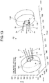
- FIG. 8 illustrates the tire wheel assemblies 104L and 104R at the reference posture P0 with two-dot chain lines, and illustrates the tire wheel assemblies 104L and 104R in a state of being tilted at the toe angle ⁇ t from the reference posture P0 with solid lines.
- the toe angle ⁇ t is an angle made between a reference surface B1 and a reference surface C1.
- the reference surface B1 is a surface that passes through the gravity center point 135 and is orthogonal to the rotation axis of each of the tire wheel assemblies 104L and 104R at the reference posture P0.
- the reference surface C1 is a surface that passes through the gravity center point 135 and is orthogonal to the rotation axis of each of the tire wheel assemblies 104L and 104R when the tire wheel assemblies 104L and 104R rotate around the Z direction serving as the rotation center in the state where the position of the gravity center point 135 is fixed.
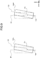
- FIG. 9 is a diagram for explaining the camber angle of the wheel.
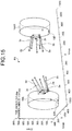
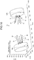
- FIG. 9 schematically illustrates the tire wheel assemblies 104L and 104R when viewed from the X direction, and illustrates the tire wheel assemblies 104L and 104R at the reference posture P0 with two-dot chain lines.
- FIG. 9 illustrates the tire wheel assemblies 104L and 104R in a state of being tilted at the camber angle ⁇ c from the reference posture P0 with solid lines.
- the camber angle ⁇ c is an angle made between the reference surface B1 and a reference surface C2.
- the reference surface C2 passes through the gravity center point 135 and is orthogonal to the rotation axis of each of the tire wheel assemblies 104L and 104R when the tire wheel assemblies 104L and 104R are tilted around the X direction serving as the rotation center in a state where the position of the gravity center point 135 is fixed.
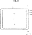
- FIG. 10 is a plan view illustrating the suspension operation terminal according to the embodiment.
- FIG. 11 is a diagram for explaining exemplary operation for operating the toe angle of the tire wheel assembly by the suspension operation terminal.
- FIG. 12 is a diagram for explaining a relation between the tire wheel assembly and the suspension when the toe angle is 20°.
- FIG. 13 is a diagram for explaining a relation between the tire wheel assembly and the suspension when the toe angle is -20°.
- the operation terminal 120 is provided such that the display 124 and the touch panel 125 overlap with each other.
- the operation terminal 120 is provided with the detection surface 120a of the touch panel 125.
- the touch panel 125 can detect a finger or the like that is in contact with or in proximity to the detection surface 120a.
- the detection surface 120a also serves as a display surface of the display 124 to display images.
- An indicator 120b which is an operation indication body operated by the operator, is displayed on the detection surface 120a by the operation of the display 124.
- the operator performs rotation operation on the operation terminal 120, thereby allowing the suspension operation system 200 to control the toe angle ⁇ t of the tire wheel assembly 104.
- the operator operates the indicator 120b displayed on the operation terminal 120, thereby allowing the suspension operation system 200 to control the camber angle ⁇ c of the tire wheel assembly 104.
- the posture of the operation terminal 120 at the reference posture P0 of each of the tire wheel assemblies 104L and 104R is referred to as a reference state Q0.
- a direction that is in parallel with the detection surface 120a and in parallel with a long side of the detection surface 120a is referred to as a first direction Dx.
- a direction that is in parallel with the detection surface 120a and orthogonal to the first direction Dx is referred to as a second direction Dy.
- a direction orthogonal to the first direction Dx and the second direction Dy is referred to as a third direction Dz.
- a virtual axis that passes through the central part of the detection surface 120a and is orthogonal to the detection surface 120a is referred to as a rotation axis B2.
- a virtual line that is orthogonal to the rotation axis B2 and in parallel with the second direction Dy is referred to as a reference line B3.
- the operator can control the toe angle ⁇ t of the tire wheel assembly 104 by performing the rotation operation on the operation terminal 120 around the rotation axis B2 serving as the rotation center.
- the reference line B3 is directed in parallel with the second direction Dy and the toe angle ⁇ t of the tire wheel assembly 104 is 0°.
- a first state Q1 illustrated in FIG. 11 the operation terminal 120 rotates in an arrow D1 direction, which is a clockwise direction, from the reference state Q0 around the rotation axis B2 serving as the rotation center.
- the sensor 126 detects a rotation angle ⁇ r.
- the rotation angle ⁇ r is an angle made between the reference line B3 in the reference state Q0 and a reference line B4 in the reference state Q1.
- the second calculator 123 calculates the operation command So by associating the rotation angle ⁇ r with the toe angle ⁇ t of the tire wheel assembly 104.
- the control device 9 receives the operation command So, and the first calculator 93 calculates the actuator length LA associated with the rotation angle ⁇ r.
- Each drive circuit 94 outputs the drive signal Sc to the corresponding actuator 5.
- the control device 9 controls the actuator length LA of each extension-retraction link 2 of the tire wheel assembly 104L on the basis of the operation command So from the operation terminal 120.
- the control device 9 performs control such that each of the actuator lengths LA of the second extension-retraction link 2b and the third extension-retraction link 2c is longer than the actuator length LA of the first extension-retraction link 2a.
- the control device 9 performs control such that each of the actuator lengths LA of the fourth extension-retraction link 2d and the fifth extension-retraction link 2e is shorter than the actuator length LA of the first extension-retraction link 2a.
- the toe angle ⁇ t of the tire wheel assembly 104L becomes +20°, for example.
- the control device 9 controls the actuator length LA of each extension-retraction link 2 of the tire wheel assembly 104R on the basis of the operation command So from the operation terminal 120. For example, the control device 9 performs control such that each of the actuator lengths LA of the second extension-retraction link 2b and the third extension-retraction link 2c is shorter than the actuator length LA of the first extension-retraction link 2a. The control device 9 performs control such that each of the actuator lengths LA of the fourth extension-retraction link 2d and the fifth extension-retraction link 2e is longer than the actuator length LA of the first extension-retraction link 2a. As a result, the toe angle ⁇ t of the tire wheel assembly 104R becomes +20°, for example.
- a second state Q2 illustrated in FIG. 11 the operation terminal 120 rotates in an arrow D2 direction, which is a counter clockwise direction, from the reference state Q0 around the rotation axis B2 serving as the rotation center.
- the sensor 126 detects the rotation angle ⁇ r.
- the second calculator 123 calculates the operation command So by associating the rotation angle ⁇ r with the toe angle ⁇ t of the tire wheel assembly 104.
- the control device 9 (refer to FIG. 5 ) outputs the drive signal Sc based on the operation command So to each actuator 5.
- the control device 9 controls the actuator length LA of each extension-retraction link 2 of the tire wheel assembly 104L on the basis of the operation command So from the operation terminal 120.
- the control device 9 performs control such that each of the actuator lengths LA of the second extension-retraction link 2b and the third extension-retraction link 2c is shorter than the actuator length LA of the first extension-retraction link 2a.
- the control device 9 performs control such that each of the actuator lengths LA of the fourth extension-retraction link 2d and the fifth extension-retraction link 2e is longer than the actuator length LA of the first extension-retraction link 2a.
- the toe angle ⁇ t of the tire wheel assembly 104L becomes -20°, for example.
- the control device 9 controls the actuator length LA of each extension-retraction link 2 of the tire wheel assembly 104R on the basis of the operation command So from the operation terminal 120.
- the control device 9 performs control such that each of the actuator lengths LA of the second extension-retraction link 2b and the third extension-retraction link 2c is longer than the actuator length LA of the first extension-retraction link 2a.
- the control device 9 performs control such that each of the actuator lengths LA of the fourth extension-retraction link 2d and the fifth extension-retraction link 2e is shorter than the actuator length LA of the first extension-retraction link 2a.
- the toe angle ⁇ t of the tire wheel assembly 104R becomes -20°, for example.
- the suspension operation system 200 can control the toe angle ⁇ t by performing the rotation operation on the operation terminal 120. Accordingly, the operator can control the toe angle ⁇ t by operating the operation terminal 120 with a similar sense to that when operating the conventional steering wheel.
- FIGS. 12 and 13 illustrate cases where the toe angle ⁇ t is +20° and the toe angle ⁇ t is -20°, respectively, which are mere examples.
- the control device 9 can control the toe angle ⁇ t continuously such that the toe angle ⁇ t is any angle between -20° and +20° inclusive.
- the control device 9 can control the toe angle ⁇ t continuously such that the toe angle ⁇ t is any angle equal to or larger than +20° or equal to or smaller than -20°.
- FIG. 14 is a diagram for explaining an exemplary operation for operating the camber angle of the wheel by the suspension operation terminal.
- FIG. 15 is a diagram for explaining a relation between the wheel and the suspension when the camber angle is -7.8°.
- FIG. 16 is a diagram for explaining a relation between the wheel and the suspension when the camber angle is +7.6°.
- the indicator 120b is located at the central portion in the first direction Dx on the detection surface 120a. At this time, the camber angle ⁇ c of the tire wheel assembly 104 is 0°.
- the indicator 120b is moved in the first direction Dx by the operator's operation. Specifically, the operator makes a finger in contact with the detection surface 120a at a position of the indicator 120b, and moves the indicator 120b in a slide manner in the first direction Dx with the contact state. That is, the operator performs so-called swipe operation.
- the touch panel 125 (refer to FIG. 5 ) detects the position and the movement of the finger that is in contact with or in proximity to the detection surface 120a.
- the display 124 moves the indicator 120b in the first direction Dx with the movement of the finger on the basis of the information from the touch panel 125.
- the second calculator 123 calculates the operation command So by associating the information about the position and the operation from the touch panel 125 with the camber angle ⁇ c of the tire wheel assembly 104.
- the control device 9 (refer to FIG. 5 ) receives the operation command So and the first calculator 93 calculates the actuator length LA associated with the information from the touch panel 125.
- Each drive circuit 94 outputs the drive signal Sc to the corresponding actuator 5.
- the control device 9 controls the actuator length LA of each extension-retraction link 2 of the tire wheel assembly 104L on the left side on the basis of the operation command So from the operation terminal 120.
- the control device 9 performs control such that each of the actuator lengths LA of the second extension-retraction link 2b and the fifth extension-retraction link 2e is shorter than the actuator length LA of the first extension-retraction link 2a.
- the control device 9 performs control such that each of the actuator lengths LA of the third extension-retraction link 2c and the fourth extension-retraction link 2d is shorter than each of the actuator lengths LA of the second extension-retraction link 2b and the fifth extension-retraction link 2e.
- the camber angle ⁇ c of the tire wheel assembly 104L becomes -7.8°, for example.
- the control device 9 controls the actuator length LA of each extension-retraction link 2 of the tire wheel assembly 104R on the right side on the basis of the operation command So from the operation terminal 120.
- the control device 9 performs control such that each of the actuator lengths LA of the third extension-retraction link 2c and the fourth extension-retraction link 2d is shorter than each of the actuator lengths LA of the first extension-retraction link 2a, the second extension-retraction link 2b, and the fifth extension-retraction link 2e.
- the camber angle ⁇ c of the tire wheel assembly 104R becomes -7.8°, for example.
- the indicator 120b is moved by the operator's operation in the opposite direction of the direction in the third state Q3 with respect to the position of the reference state Q0. Specifically, the operator makes the finger in contact with the indicator 120b and moves the indicator 120b in a slide manner in the opposite direction of the first direction Dx with the state of the finger being in contact with the detection surface 120a. Accordingly, the indicator 120b is moved in the opposite direction of the first direction Dx with the movement of the finger.
- the touch panel 125 (refer to FIG. 5 ) detects the position of the finger that is in contact with or in proximity to the detection surface 120a.
- the second calculator 123 calculates the operation command So by associating the information about the position and the operation from the touch panel 125 with the camber angle ⁇ c of the tire wheel assembly 104.
- the control device 9 (refer to FIG. 5 ) outputs the drive signal Sc on the basis of the operation command So to each actuator 5.
- the control device 9 controls the actuator length LA of each extension-retraction link 2 of the tire wheel assembly 104L on the basis of the operation command So from the operation terminal 120.
- the control device 9 performs control such that each of the actuator lengths LA of the third extension-retraction link 2c and the fourth extension-retraction link 2d is longer than each of the actuator lengths LA of the first extension-retraction link 2a, the second extension-retraction link 2b, and the fifth extension-retraction link 2e.
- the camber angle ⁇ c of the tire wheel assembly 104L becomes +7.6°, for example.
- the control device 9 controls the actuator length LA of each extension-retraction link 2 of the tire wheel assembly 104R on the basis of the operation command So from the operation terminal 120.
- the control device 9 performs control such that each of the actuator lengths LA of the third extension-retraction link 2c and the fourth extension-retraction link 2d is shorter than each of the actuator lengths LA of the first extension-retraction link 2a, the second extension-retraction link 2b, and the fifth extension-retraction link 2e.
- the camber angle ⁇ c of the tire wheel assembly 104R becomes +7.6°, for example.
- the operator can control the camber angle ⁇ c of the tire wheel assemblies 104L and 104R by operating the indicator 120b, which is the operation indication body displayed on the operation terminal 120. Accordingly, the operator can check the state of the camber angle ⁇ c by visually recognizing the position of the indicator 120b.
- the suspension operation system 200 allows a larger degree of freedom in operating the operation terminal 120 than that of the conventional steering wheels, thereby allowing easy control of the toe angle ⁇ t and the camber angle ⁇ c of the tire wheel assemblies 104L and 104R.
- the suspension operation system 200 can increase a degree of freedom in operating the postures of the tire wheel assemblies 104L and 104R.
- FIGS. 15 and 16 illustrate cases where the camber angle ⁇ c is +7.6° and -7.8°, respectively, which are mere examples.
- the control device 9 can control the camber angle ⁇ c continuously such that the camber angle ⁇ t is any angle between -7.8° and +7.6° inclusive.
- the control device 9 can control the camber angle ⁇ c continuously such that the camber angle ⁇ c is any angle equal to or larger than +7.6° or equal to or smaller than -7.8°.
- the tire wheel assemblies 104R and 104L are tilted in the same direction.
- the control may be performed such that the tire wheel assemblies 104R and 104L are tilted in mutually opposite directions.
- FIGS. 11 and 14 The operation methods of the operation terminal 120 illustrated in FIGS. 11 and 14 are mere examples, and may be changed as appropriate.
- FIG. 17 is a diagram for explaining another exemplary operation for operating the camber angle of the wheel by the suspension operation terminal.
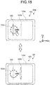
- FIG. 18 is a diagram for explaining still another exemplary operation for operating the camber angle of the wheel by the suspension operation terminal.
- the indicator 120b is moved in the first direction Dx by the operator's operation. Specifically, the operator makes a finger in contact with a region 120c on the right side of the indicator 120b on the detection surface 120a with the state of the indicator 120b being located at the center (in the reference state Q0).
- the touch panel 125 detects the contact of the finger with the region 120c.
- the display 124 moves the indicator 120b in the first direction Dx with the movement of the finger on the basis of the information from the touch panel 125.
- the second calculator 123 calculates the operation command So by associating the positional information from the touch panel 125 with the camber angle ⁇ c of the tire wheel assembly 104.
- the control device 9 (refer to FIG. 5 ) outputs the drive signal Sc on the basis of the operation command So to each actuator 5.
- the camber angle ⁇ c of the tire wheel assemblies 104L and that of 104R are controlled in the same manner as FIG. 15 .
- the state returns to the reference state Q0.
- the touch panel 125 detects that the finger is not in contact with the region 120c.
- the display 124 moves the indicator 120b to the center of the detection surface 120a on the basis of the information from the touch panel 125.
- the second calculator 123 calculates the operation command So by associating the positional information from the touch panel 125 with the camber angle ⁇ c of the tire wheel assembly 104.
- the control device 9 (refer to FIG. 5 ) outputs the drive signal Sc on the basis of the operation command So to each actuator 5.
- the camber angle ⁇ c of each of the tire wheel assemblies 104L and 104R is controlled to 0° in the same manner as FIG. 6 .
- a fourth state Q4a illustrated in FIG. 18 the indicator 120b is moved in the opposite direction of the first direction Dx by the operator's operation. Specifically, the operator makes a finger in contact with a region 120d on the left side of the indicator 120b on the detection surface 120a with the state of the indicator 120b being located at the center (in the reference state Q0).
- the touch panel 125 detects the contact of the finger with the region 120d.
- the display 124 moves the indicator 120b in the opposite direction of the first direction Dx with the movement of the finger on the basis of the information from the touch panel 125.
- the second calculator 123 calculates the operation command So by associating the positional information from the touch panel 125 with the camber angle ⁇ c of the tire wheel assembly 104.
- the control device 9 (refer to FIG. 5 ) outputs the drive signal Sc on the basis of the operation command So to each actuator 5.
- the camber angle ⁇ c of each of the tire wheel assemblies 104L and 104R is controlled in the same manner as FIG. 16 .
- the state returns to the reference state Q0.
- the touch panel 125 detects that the finger is not in contact with the region 120d.
- the display 124 moves the indicator 120b to the center of the detection surface 120a on the basis of the information from the touch panel 125.
- the second calculator 123 calculates the operation command So by associating the positional information from the touch panel 125 with the camber angle ⁇ c of the tire wheel assembly 104.
- the control device 9 (refer to FIG. 5 ) outputs the drive signal Sc on the basis of the operation command So to each actuator 5.
- the camber angle ⁇ c of each of the tire wheel assemblies 104L and 104R is controlled to 0° in the same manner as FIG. 6 .
- FIG. 19 is a diagram for explaining another exemplary operation for operating the posture of the wheel by the suspension operation terminal.
- the display 124 displays a first operation button 120e and a second operation button 120f.
- the first operation button 120e and the second operation button 120f are used for switching the control of the toe angle ⁇ t and the camber angle ⁇ c, respectively.
- the state proceeds to a fifth state Q5, in which the display 124 displays toe angle control buttons 120g and 120h.
- the toe angle control button 120g on the right side the toe angle ⁇ t of each of the tire wheel assemblies 104L and 104R is changed to that in the plus Y direction.
- the toe angle control button 120h on the left side the toe angle ⁇ t of each of the tire wheel assemblies 104L and 104R is changed to that in the minus Y direction.
- the state returns to the reference state Q0a.
- the state proceeds to a sixth state Q6, in which the display 124 displays camber angle control buttons 120j and 120k.
- the camber angle control button 120j When the operator operates the camber angle control button 120j on the right side, the camber angle ⁇ c of each of the tire wheel assemblies 104L and 104R is changed to that in the plus Y direction.
- the camber angle control button 120k on the left side When the operator operates the camber angle control button 120k on the left side, the camber angle ⁇ c of each of the tire wheel assemblies 104L and 104R is changed to that in the minus Y direction.
- the toe angle ⁇ t and the camber angle ⁇ c of the tire wheel assemblies 104L and 104R can be controlled by operating the various buttons. This can allow simple control of the operation terminal 120.
- the structures of the control device 9 and the operation terminal 120 illustrated in FIG. 5 and the like can be changed as appropriate.
- the operation terminal 120 may transmit, to the control device 9, the positional information and the operation information from the touch panel 125 or information about the rotation angle from the sensor 126.
- the detection surface 120a of the operation terminal 120 illustrated in FIG. 10 and the like can also be changed as appropriate.
- the shape and the size of the indicator 120b are not limited to those exemplarily illustrated in FIG. 10 and the like.
- the operation terminal 120 can wirelessly communicate with the control device 9.
- the operation terminal 120 may have a wired connection to the control device 9.
- the suspension operation system 200 can change a caster angle, a tread width, and a wheelbase, for example, besides the toe angle ⁇ t and the camber angle ⁇ c.
- the caster angle is, when the vehicle 10 is viewed from the horizontal direction, an angle made by a straight line parallel with the longitudinal direction of the shock absorber 11 with respect to the vertical line.
- the tread width is a distance between the centers of the left and right wheels 102.
- the wheelbase is a distance between the centers of the front and rear wheels 102.
- the suspension 1 is not necessarily applied to vehicles with the hub units 101 having motors and the like built-in.
- the suspension 1 may be connected to the hub bearing supporting the wheel 102.
- the suspension 1 does not necessarily include five extension-retraction links 2.
- the suspension 1 is only required to include a plurality of links, at least one of which should be the extension-retraction link 2.
- the suspension operation system 200 includes: the suspension 1 that includes a plurality of links (extension-retraction links 2) supporting the wheel (the tire wheel assembly 104), at least one or more of the links including the actuator 5 increasing and decreasing its length in the axial direction; the control device 9 that supplies the drive signal Sc to the actuator 5 to control the operation of the suspension 1; and the suspension operation terminal (operation terminal 120) that operates the suspension 1.
- the operation terminal 120 includes: the detector that detects the operation input information to the operation terminal 120; and the communicator (the second communicator 122) that transmits the information about the target posture of the wheel, the information being based on the operation input information, to the control device 9 as the operation command So.
- the control device 9 includes: the first calculator 93 that calculates the length of the actuator 5 on the basis of the operation command So; and the drive circuit 94 that produces the drive signal Sc on the basis of the information from the first calculator 93.
- the operator can control the suspension 1 including the plurality of extension-retraction links 2 by operating the operation terminal 120, thereby allowing a larger degree of freedom in operating the suspension 1 than the conventional steering wheels.
- the suspension operation system 200 can easily control the posture of the wheel by operating the suspension 1 including the plurality of extension-retraction links 2.
- the operation terminal 120 includes the second calculator 123 that calculates the operation command So on the basis of the operation input information.
- the operation command So includes the information about at least one of the toe angle ⁇ t and the camber angle ⁇ c of the wheel. This makes it possible to control the toe angle ⁇ t and the camber angle ⁇ c of the wheel by the operation of the operation terminal 120, thereby allowing an increased degree of freedom in operating the posture of the wheel.
- the operation terminal 120 further includes the display 124 that displays images.
- the detector includes the touch panel 125 that detects touch input to the detection surface 120a.
- the second calculator 123 calculates the operation command So by associating the operation input information from the touch panel 125 provided by the slide operation performed on the operation indication body (indicator 120b) displayed on the detection surface 120a with the camber angle ⁇ c of the wheel. Accordingly, the operator can control the camber angle ⁇ c of the wheel by operating the touch panel 125. The operator can determine whether the camber angle ⁇ c of the wheel is operated by performing the slide operation on the displayed indicator 120b. Consequently, the suspension operation system 200 can easily operate the camber angle ⁇ c of the wheel.
- the vehicle using the suspension operation system 200 can adjust the motion performance of the vehicle by controlling the camber angles of the wheels in accordance with running conditions and running environments.
- the detector includes the sensor 126 that detects the rotation around the direction orthogonal to the detection surface 120a of the operation terminal 120, the direction serving as the rotation center axis.
- the second calculator 123 calculates the toe angle ⁇ t of the wheel on the basis of the rotation angle of the operation terminal 120 from the sensor 126. Accordingly, the operator can control the toe angle ⁇ t of the wheel by performing the rotation operation on the operation terminal 120.
- the suspension operation system 200 associates the rotation operation of the operation terminal 120 with the toe angle ⁇ t of the wheel, in the same manner as the operation of the conventional steering wheel, thereby allowing easy control of the toe angle ⁇ t of the wheel.
- the communicator (the second communicator 122) wirelessly transmits the operation command So to the control device 9. Accordingly, the operation terminal 120 can wirelessly communicate with the control device 9. Consequently, the operation terminal 120 can be stored at a location where the operation terminal 120 does not interfere with occupants when the operation terminal 120 is not operated such as a case where the vehicle is in an automatic drive mode. This can lead to improved comfortableness.
- the operation terminal 120 includes: the detector that detects the operation input information for operating the suspension 1 including the plurality of extension-retraction links 2 supporting the wheel; and the communicator (the second communicator 122) that transmits the information about the target posture of the wheel, the information being calculated based on the operation input information, to the control device 9 as the operation command So.
- the operation terminal 120 operates the posture of the wheel by driving the actuator 5 included in at least one or more of the extension-retraction links 2 so as to increase or decrease the length in the axial direction of the actuator 5 on the basis of the operation command So.
- the operator can control the suspension 1 including the plurality of extension-retraction links 2 by operating the operation terminal 120, thereby allowing a larger degree of freedom in operating the suspension 1 than the conventional steering wheels.
- Operating the suspension including the plurality of links with the operation terminal 120 allows easy control of the posture of the wheel.
- the operation terminal 120 further includes: the calculator (the second calculator 123) that calculates the operation command So on the basis of the operation input information; and the display 124 that displays images.
- the detector includes the touch panel 125 that detects touch input to the detection surface 120a.
- the display 124 displays the indicator 120b associated with the camber angle ⁇ c of the wheel on the detection surface 120a.
- the second calculator 123 calculates the operation command So by associating the operation input information from the touch panel 125 provided by the slide operation performed on the indicator 120b with the camber angle ⁇ c of the wheel. Accordingly, the operator can control the camber angle ⁇ c of the wheel by operating the touch panel 125.
- the operator can determine whether the camber angle ⁇ c of the wheel is operated by performing the slide operation on the displayed indicator 120b. Consequently, the operation terminal 120 can easily operate the camber angle of the wheel.
Landscapes
- Engineering & Computer Science (AREA)
- Mechanical Engineering (AREA)
- General Engineering & Computer Science (AREA)
- Chemical & Material Sciences (AREA)
- Combustion & Propulsion (AREA)
- Transportation (AREA)
- Theoretical Computer Science (AREA)
- Physics & Mathematics (AREA)
- General Physics & Mathematics (AREA)
- Human Computer Interaction (AREA)
- Vehicle Body Suspensions (AREA)
- Telephone Function (AREA)
- User Interface Of Digital Computer (AREA)
- Selective Calling Equipment (AREA)
Abstract
Description
- The present invention relates to a suspension operation system and a suspension operation terminal. Background
- A vehicle has a suspension provided between its body and a wheel. The suspension is a device that makes vibrations due to fluctuation of a road surface less likely to be transmitted to the vehicle body, and that positions the wheel. A multi-link suspension is known as one of suspension types. Patent Literature 1, for example, describes an example of the multi-link suspension.
Patent Literature 2 describes a work vehicle operation system that performs remote control on a vehicle by using a portable information terminal such as a smartphone and a tablet terminal. -
- Patent Literature 1: Japanese Laid-open Patent Publication No.
2015-155255 - Patent Literature 2: Japanese Patent No.
5955254 - In some cases, a relative posture of the wheel with respect to the vehicle body is required to be changed in accordance with motion performance required for the vehicle. However, a conventional steering wheel has a small degree of freedom in operation, which leads to difficulty in operating a wheel posture with ease.
Patent Literature 2 does not describe suspension operation. - The present invention has been made in view of the above, and aims to provide a suspension operation system and a suspension operation terminal that can easily operate a relative posture of the wheel with respect to the vehicle body.
- To achieve the purpose described above, a suspension operation system according to an aspect of the present invention includes: a suspension that includes a plurality of links supporting a wheel, at least one or more of the links having an actuator increasing or decreasing a length of the actuator in an axial direction; a control device that supplies a drive signal to the actuator to control operation of the suspension; and a suspension operation terminal that operates the suspension. The suspension operation terminal includes: a detector that detects operation input information to the suspension operation terminal; and a communicator that transmits information about a target posture of the wheel, the information being based on the operation input information, to the control device as an operation command. The control device includes: a first calculator that calculates the length of the actuator on the basis of the operation command; and a drive circuit that produces the drive signal on the basis of information from the first calculator.
- Accordingly, an operator can control the suspension including the plurality of extension-retraction links by operating the suspension operation terminal. Consequently, the degree of freedom in operating the suspension can be more increased than the conventional steering wheels. The suspension operation system can easily control the posture of the wheel by operating the suspension including the plurality of extension-retraction links.
- As a preferred aspect of the suspension operation system, the suspension operation terminal includes a second calculator that calculates the operation command on the basis of the operation input information. The operation command includes information about at least one of a toe angle or a camber angle of the wheel. This makes it possible to control the toe angle and the camber angle of the wheel by the operation of the suspension operation terminal, thereby allowing an increased degree of freedom in operating the posture of the wheel.
- As a preferred aspect of the suspension operation system, the suspension operation terminal further includes a display that displays an image. The detector includes a touch panel that detects touch input to a detection surface. The second calculator calculates the operation command by associating operation input information from the touch panel provided by slide operation performed on an operation indication body displayed on the detection surface with the camber angle of the wheel. Accordingly, the operator can control the camber angle of the wheel by operating the touch panel. The operator can determine whether the camber angle of the wheel is operated by performing the slide operation on the displayed operation indication body. Consequently, the suspension operation system can easily operate the camber angle of the wheel. The vehicle using the suspension operation system can adjust the motion performance of the vehicle by controlling the camber angles of the wheels in accordance with running conditions and running environments.
- As a preferred aspect of the suspension operation system, the detector includes a sensor that detects rotation around a direction orthogonal to a detection surface of the suspension operation terminal, the direction serving as a rotation center axis. The second calculator calculates the operation command by associating a rotation angle of the suspension operation terminal, the rotation angle being obtained from the sensor, with the toe angle of the wheel. Accordingly, the operator can control the toe angle of the wheel by performing the rotation operation on the operation terminal. The suspension operation system associates the rotation operation of the suspension operation terminal with the toe angle of the wheel in the same manner as the operation of the conventional steering wheel, thereby making it possible to easily control the toe angle of the wheel.
- As a preferred aspect of the suspension operation system, the communicator wirelessly transmits the operation command to the control device. This makes it possible for the suspension operation terminal to wirelessly communicate with the control device. Accordingly, the suspension operation terminal can be stored at a location where the suspension operation terminal does not interfere with occupants when the suspension operation terminal is not operated, such as a case where the vehicle is in an automatic drive mode, which improves comfortableness.
- A suspension operation terminal according to another aspect of the present invention includes: a detector that detects operation input information for operating a suspension including a plurality of links supporting a wheel; and a communicator that wirelessly transmits information about a target posture of the wheel, the information being calculated on the basis of the operation input information, to a control device as an operation command. The suspension operation terminal operates a posture of the wheel by operating an actuator to increase or decrease a length of the actuator in an axial direction on the basis of the operation command, the actuator being included in at least one or more of the links.
- Accordingly, the operator can control the suspension including the plurality of extension-retraction links by operating the suspension operation terminal. Consequently, the degree of freedom in operating the suspension can be more increased than the conventional steering wheels. Operating the suspension including the plurality of links with the operation terminal makes it possible to easily control the posture of the wheel.
- As a preferred aspect of the suspension operation terminal, the suspension operation terminal further includes: a calculator that calculates the operation command on the basis of the operation input information; and a display that displays an image. The detector includes a touch panel that detects touch input to a detection surface. The display displays an operation indication body on the detection surface, the operation indication body being associated with a camber angle of the wheel. The calculator calculates the operation command by associating operation input information from the touch panel provided by slide operation performed on the operation indication body with the camber angle of the wheel. Accordingly, the operator can control the camber angle of the wheel by operating the touch panel. The operator can determine whether the camber angle of the wheel is operated by performing the slide operation on the displayed operation indication body. Consequently, the suspension operation terminal can easily operate the camber angle of the wheel.
- According to the present invention, it is possible to easily operate the relative posture of the wheel with respect to the vehicle body.
-
-
FIG. 1 is a perspective view of suspensions of a suspension operation system in an embodiment. -
FIG. 2 is a plan view of an extension-retraction link of the suspension operation system in the embodiment. -
FIG. 3 is a cross-sectional view taken along A-A inFIG. 2 . -
FIG. 4 is a cross-sectional view of a second universal joint. -
FIG. 5 is a block diagram illustrating a schematic structure of the suspension operation system in the embodiment. -
FIG. 6 is a diagram for explaining a relation between a length of an actuator and a posture of a tire wheel assembly. -
FIG. 7 is a diagram for explaining a contact patch center. -
FIG. 8 is a diagram for explaining a toe angle of a wheel. -
FIG. 9 is a diagram for explaining a camber angle of the wheel. -
FIG. 10 is a plan view illustrating a suspension operation terminal in the embodiment. -
FIG. 11 is a diagram for explaining exemplary operation for operating the toe angle of the tire wheel assembly by the suspension operation terminal. -
FIG. 12 is a diagram for explaining a relation between the tire wheel assembly and the suspension when the toe angle is 20°. -
FIG. 13 is a diagram for explaining a relation between the tire wheel assembly and the suspension when the toe angle is -20°. -
FIG. 14 is a diagram for explaining an exemplary operation for operating the camber angle of the wheel by the suspension operation terminal. -
FIG. 15 is a diagram for explaining a relation between the wheel and the suspension when the camber angle is -7.8°. -
FIG. 16 is a diagram for explaining a relation between the wheel and the suspension when the camber angle is +7.6°. -
FIG. 17 is a diagram for explaining another exemplary operation for operating the camber angle of the wheel by the suspension operation terminal. -
FIG. 18 is a diagram for explaining still another exemplary operation for operating the camber angle of the wheel by the suspension operation terminal. -
FIG. 19 is a diagram for explaining another exemplary operation for operating the posture of the wheel by the suspension operation terminal. - The following describes the present invention in detail with reference to the accompanying drawings. The following embodiment for carrying out the invention (hereinafter described as the embodiment) does not limit the invention. The constituent elements in the embodiment described below include elements that can be easily conceived of by a person skilled in the art, elements substantially equivalent thereto, and elements within a so-called range of equivalents. The constituent elements disclosed in the following embodiment can be combined as appropriate.
-
FIG. 1 is a perspective view of suspensions of a suspension operation system in the embodiment.FIG. 2 is a plan view of an extension-retraction link of the suspension operation system according to the embodiment.FIG. 3 is a cross-sectional view taken along A-A inFIG. 2 .FIG. 4 is a cross-sectional view of a second universal joint. Avehicle 10 in the embodiment includeswheels 102,hub units 101, vehiclebody side members 18,hub carriers 19, suspensions 1, and acontrol device 9. For example, thevehicle 10 includes fourwheels 102, each of which includes thehub unit 101. - The
hub unit 101 has, for example, a hub bearing, two motors, and a speed changer, built-in. Thehub unit 101 rotatably supports thewheel 102 and drives thewheel 102. The vehiclebody side member 18 is fixed to the vehicle body. Thehub carrier 19 is a member fixed to thehub unit 101. Thehub carrier 19 is also called a knuckle. - The suspension 1 is a device that connects the vehicle body (chassis) of the
vehicle 10 and thehub unit 101. The suspension 1 is a multi-link suspension. As illustrated inFIG. 1 , the suspension 1 includes ashock absorber 11 and five extension-retraction links 2 for eachwheel 102. - The
shock absorber 11 is a device that reduces shock transmitted to the vehicle body from a road surface during vehicle running. One end of theshock absorber 11 is fixed to the vehicle body. The other end of theshock absorber 11 is fixed to thehub carrier 19. Theshock absorber 11 can extend and retract in an upper-lower direction. - The extension-
retraction link 2 connects the vehiclebody side member 18 and thehub carrier 19. As illustrated inFIG. 1 , two extension-retraction links 2 are arranged on an upper side of the rotation axis of thewheel 102. Three extension-retraction links 2 are arranged on a lower side of the rotation axis of thewheel 102. As illustrated inFIG. 2 , the extension-retraction link 2 includes astationary shaft 3, amovable shaft 4, a first universal joint 6a, a second universal joint 6b, and anactuator 5. - The
stationary shaft 3 is connected to the vehicle body side member 18 (refer toFIG. 1 ) with the first universal joint 6a interposed therebetween. Thestationary shaft 3 has a tubular shape. As illustrated inFIG. 3 , thestationary shaft 3 includes afirst member 31 and asecond member 32. Thefirst member 31 and thesecond member 32 are connected to each other with fastener members. The first universal joint 6a is attached to thefirst member 31. - The
movable shaft 4 is connected to the hub carrier 19 (refer toFIG. 1 ) with the second universal joint 6b interposed therebetween. As illustrated inFIG. 3 , themovable shaft 4 is a hollow member having aninternal space 40. Part of themovable shaft 4 is located inside thestationary shaft 3. Themovable shaft 4 can slide with respect to thestationary shaft 3. The slidable length of themovable shaft 4 is limited by astopper 45 provided to themovable shaft 4. Thestopper 45 is disposed in agroove 315 provided on an inner circumferential surface of thefirst member 31. When thestopper 45 reaches the end of thegroove 315, thestopper 45 is in contact with thefirst member 31, thereby stopping themovable shaft 4. This prevents themovable shaft 4 from dropping off from thestationary shaft 3. - The first universal joint 6a connects the
stationary shaft 3 to the vehicle body side member 18 (refer toFIG. 1 ) such that thestationary shaft 3 can rotate and swing with respect to the vehiclebody side member 18. The second universal joint 6b connects themovable shaft 4 to the hub carrier 19 (refer toFIG. 1 ) such that themovable shaft 4 can rotate and swing with respect to thehub carrier 19. In the description about the capability of rotation and swing, the rotation means rotation around a straight line L1b (refer toFIG. 4 ) serving as the rotation center, while the swing means movement by which an angle θ made between the straight line L1b and a straight line L2b changes. The straight line L1b is a straight line passing through the gravity center of each cross-sectional surface when anarm 61, which is described later, is cut with a plane orthogonal to the longitudinal direction of thearm 61. The straight line L2b is orthogonal to a circle formed by an outer shape of anexternal bush 63, which is described later, and passes through the center of the circle. An intersection Mb (refer toFIG. 14 ) of the straight lines L1b and L2b is the center of an armconvex surface 617p having a spherical surface shape, which is described later. In the embodiment, the first universal joint 6a and the second universal joint 6b have the same structure. In the following detailed description, the second universal joint 6b is described as an example. The description of the seconduniversal joint 6b can also be applied to that of the first universal joint 6a. - As illustrated in
FIGS. 3 and4 , the second universal joint 6b includes ahousing 60, thearm 61, theexternal bush 63, aninternal bush 65,elastic members 67, and a supportingmember 69. Thehousing 60 is formed integrally with the end portion of themovable shaft 4. Thehousing 60 has a tubular shape. Thehousing 60 of the first universal joint 6a is formed integrally with thefirst member 31. - The
arm 61 is a member connected to the hub carrier 19 (refer toFIG. 1 ). Thearm 61 is made of metal. The metal used for thearm 61 is steel, for example. Part of thearm 61 is located inside thehousing 60. As illustrated inFIG. 4 , thearm 61 includes afastening portion 611, aflange portion 613, anintermediate portion 615, and a slidingportion 617. Thefastening portion 611 and theflange portion 613 are located outside thehousing 60. Thefastening portion 611 is a columnar member having a thread on its outer circumferential surface. Theflange portion 613 is a member that is located on thehousing 60 side of thefastening portion 611 and has a substantially conical shape in which the diameter of theflange portion 613 increases toward thehousing 60. Theintermediate portion 615 is a member that extends toward thehousing 60 side from theflange portion 613 and has a substantially columnar shape. Theintermediate portion 615 has two parallel flat surfaces on its outer circumferential surface. The slidingportion 617 is a member that is located on thehousing 60 side of theintermediate portion 615 and has a substantially hemispherical shape. The slidingportion 617 includes the armconvex surface 617p, an armconcave surface 617q, and anarm end surface 617e. The armconvex surface 617p is the external surface of the slidingportion 617 and has a spherical surface shape. The armconcave surface 617q is the internal surface of the slidingportion 617 and has a spherical surface shape. The center of the armconcave surface 617q is the same as the center of the armconvex surface 617p. Thearm end surface 617e is the end surface of the slidingportion 617 that connects the armconvex surface 617p and the armconcave surface 617q. Part of thearm end surface 617e is formed in a conical surface shape. - As illustrated in
FIG. 4 , theexternal bush 63 is an annular member located between the inner circumferential surface of thehousing 60 and thearm 61. Theexternal bush 63 is formed of metal. The metal used for theexternal bush 63 is brass, for example. Theexternal bush 63 is press-fitted into thehousing 60. Theexternal bush 63 includes a bush concave surface 63q serving as its inner circumferential surface. The bush concave surface 63q has a spherical surface shape and is in contact with the armconvex surface 617p. The center and the radius of the bush concave surface 63q are the same as those of the armconvex surface 617p. - As illustrated in
FIG. 4 , theinternal bush 65 is located inside the slidingportion 617 of thearm 61. Theinternal bush 65 is located on the opposite side of theexternal bush 63 with respect to the slidingportion 617. Theinternal bush 65 is formed of metal. The metal used for theinternal bush 65 is brass, for example. Theinternal bush 65 includes ahead portion 651 and abody portion 653. Thehead portion 651 has a substantially hemispherical shape and a bushconvex surface 651p. The bushconvex surface 651p is a spherical surface and in contact with the armconcave surface 617q. Accordingly, the slidingportion 617 is sandwiched between the bushconvex surface 651p of theinternal bush 65 and the bush concave surface 63q of theexternal bush 63. The center and the radius of the bushconvex surface 651p are the same as those of the armconcave surface 617q. Thebody portion 653 is a substantially cylindrical member extending from thehead portion 651 toward the opposite side of the bushconvex surface 651p. - The supporting
member 69 supports theinternal bush 65. As illustrated inFIG. 4 , the supportingmember 69 is attached inside thehousing 60. The supportingmember 69 is formed of metal. The metal used for the supportingmember 69 is steel, for example. The supportingmember 69 includes a male screw 691, afirst recess 693, and asecond recess 695. The male screw 691 engages with afemale screw 601 provided to thehousing 60. Thefirst recess 693 is a dent that opens toward theinternal bush 65 and has a truncated cone shape. The bottom surface of thefirst recess 693 is a plane orthogonal to the extending direction of thebody portion 653 of theinternal bush 65. Thesecond recess 695 is a dent that is provided on the bottom surface of thefirst recess 693 and has a columnar shape. Thebody portion 653 is fitted in thesecond recess 695 and guided by the inner circumferential surface of thesecond recess 695. - As illustrated in
FIG. 4 , theelastic members 67 are located between theinternal bush 65 and the supportingmember 69 and press theinternal bush 65 toward thearm 61. Theelastic member 67 is a disc spring, for example. Twoelastic members 67 are arranged overlapping with each other between thebody portion 653 and the bottom surface of thesecond recess 695. - The inside of the
housing 60 is filled with lubricant. The lubricant is grease, for example. The slidingportion 617 of thearm 61 can move along theexternal bush 63 and theinternal bush 65. Accordingly, thearm 61 can rotate and swing relatively with respect to theexternal bush 63 and theinternal bush 65. As illustrated inFIG. 4 , thearm end surface 617e is in contact with the bottom surface of thefirst recess 693. When thearm end surface 617e is in contact with the bottom surface of thefirst recess 693, agap 60c is formed between thearm 61 and thehousing 60. - The materials used for the respective first universal joint 6a and second universal joint 6b are not limited to those described above. The number of
elastic members 67 included in the first universal joint 6a and the second universal joint 6b is not limited to any specific number. The number may be one or three or more. The first universal joint 6a and the second universal joint 6b do not necessarily have the same structure. - As illustrated in
FIG. 3 , theactuator 5 includes amotor 51, ascrew shaft 57, a bearingunit 55, anut 59, asnap ring 58, and aclutch 7. - The
motor 51 is fixed to the end portion of thestationary shaft 3 on the opposite side of themovable shaft 4. Themotor 51 includes an encoder that detects a rotation angle of a rotor. Ashaft 511 that rotates together with the rotor of themotor 51 extends toward the inside of thestationary shaft 3. - The
screw shaft 57 is connected to theshaft 511 with the clutch 7 interposed therebetween. Thescrew shaft 57 rotates together with theshaft 511 around a rotation axis AX serving as the rotation center. Part of thescrew shaft 57 is inserted into themovable shaft 4. The end of thescrew shaft 57 is located in theinternal space 40 of themovable shaft 4. Thescrew shaft 57 passes through thenut 59. - The bearing
unit 55 supports thescrew shaft 57 such that thescrew shaft 57 can rotate with respect to thestationary shaft 3. The bearingunit 55 is fixed to thestationary shaft 3 and hasbearings 551 built-in. Thebearings 551 are fitted in the outer circumferential surface of thescrew shaft 57. - The
nut 59 is fixed to themovable shaft 4 with thesnap ring 58 and moves together with themovable shaft 4. Thenut 59 includes twoprotrusions 591 protruding in the radius direction. Theprotrusions 591 are fitted in arecess 49 provided on the end surface of themovable shaft 4. This restricts the rotation of thenut 59. Thesnap ring 58 is fitted in a substantially annular groove provided on the inner circumferential surface of themovable shaft 4 and positions thenut 59 in the axial direction. - The
control device 9 illustrated inFIG. 1 is a computer, which includes a central processing unit (CPU), a read only memory (ROM), and a random access memory (RAM), for example. Thecontrol device 9 is an electronic control unit (ECU) mounted on thevehicle 10, for example. Thecontrol device 9 is electrically connected to themotor 51 of each extension-retraction link 2. Thecontrol device 9 controls themotors 51 individually. As a result, the length of each extension-retraction link 2 (position of each movable shaft 4) changes. - In the embodiment, the length of the extension-
retraction link 2 is described as an actuator length LA illustrated inFIG. 3 . The actuator length LA is a length between an intersection Ma of the first universal joint 6a and an intersection Mb of the second universal joint 6b. The firstuniversal joint 6a can swing around the intersection Ma serving as the swing center. The seconduniversal joint 6b can swing around the intersection Mb serving as the swing center. - The following describes a
suspension operation system 200 that operates the suspension 1 including the plurality of extension-retraction links 2.FIG. 5 is a block diagram illustrating a schematic structure of the suspension operation system according to the embodiment. Thesuspension operation system 200 illustrated inFIG. 5 has the suspension 1,tire wheel assemblies control device 9, and anoperation terminal 120. - The suspension 1 has the structure illustrated in
FIGS. 1 to 3 . The suspension 1 has a plurality of extension-retraction links, i.e., a first extension-retraction link 2a, a second extension-retraction link 2b, ..., and a fifth extension-retraction link 2e. The first extension-retraction link 2a, the second extension-retraction link 2b, ..., and the fifth extension-retraction link 2e are simply described as the extension-retraction link 2 when they do not need to be described individually. The first extension-retraction link 2a, the second extension-retraction link 2b, ..., and the fifth extension-retraction link 2e have afirst actuator 5a, a second actuator 5b, ..., and afifth actuator 5e, respectively. Thefirst actuator 5a, the second actuator 5b, ..., and thefifth actuator 5e are simply described as theactuator 5 when they do not need to be described individually. Operation of eachactuator 5 increases or decreases the length in the axial direction of the extension-retraction link 2. - The
control device 9 supplies a drive signal Sc to theactuator 5 to control the operation of the suspension 1. Accordingly, thecontrol device 9 can control the postures of thetire wheel assemblies FIG. 5 illustrates atire wheel assembly 104, which is one of the tire wheel assemblies, for easy explanation. As illustrated inFIG. 1 , thecontrol device 9 is provided for the twotire wheel assemblies control device 9 can control the postures of the twotire wheel assemblies control device 9 may control the posture of thetire wheel assembly 104 individually. Alternatively, thecontrol device 9 can be provided for three or more suspensions 1 and control the plurality of suspensions 1 and thetire wheel assemblies 104. - The
control device 9 includes afirst communicator 92, a first calculator 93, afirst drive circuit 94a, asecond drive circuit 94b, ..., afifth drive circuit 94e, and afirst storage 95. - The
first communicator 92, which is a wireless communication module, wirelessly receives, via anantenna 92a, an operation command So transmitted from asecond communicator 122 of theoperation terminal 120. Thefirst communicator 92 demodulates the operation command So, which is a high frequency signal, to produce a target posture signal Sa. Thefirst communicator 92 supplies the target posture signal Sa to the first calculator 93. The target posture signal Sa is information about a target posture of thetire wheel assembly 104. The target posture signal Sa is information about a toe angle θt (refer toFIG. 8 ) and a camber angle θc (refer toFIG. 9 ), for example. The wireless communication between thecontrol device 9 and theoperation terminal 120 uses a communication standard such as Wi-Fi (trademark), 3G, and Bluetooth (trademark). The communication standard is not limited to any specific standard, and may be another standard. - The
first storage 95 includes a storage medium such as a ROM. Thefirst storage 95 stores actuator information Sb, which is information about eachactuator 5. The actuator information Sb is information about a maximum value of the actuator length LA, a minimum value of the actuator length LA, a relation between the actuator length LA and the posture of thetire wheel assembly 104, for example. Thefirst storage 95 may store information such as an ID or a password of theoperation terminal 120. In this case, thecontrol device 9 collates the information such as the ID or the password stored in thefirst storage 95 with an ID or a password transmitted from theoperation terminal 120 to determine whether theoperation terminal 120 is an operable terminal. - The first calculator 93 includes a CPU, for example. The first calculator 93 calculates length command signals SLa, SLb, ..., and SLe on the basis of the target posture signal Sa and the actuator information Sb. The length command signals SLa, SLb, ..., and SLe are information about the actuator lengths LA of the
respective actuators 5, the actuator lengths LA causing thetire wheel assembly 104 to achieve the target posture (the toe angle θt and the camber angle θc). The first calculator 93 outputs the length command signals SLa, SLb, ..., and SLe to thefirst drive circuit 94a, thesecond drive circuit 94b, ..., and thefifth drive circuit 94e, respectively. - The
first drive circuit 94a, thesecond drive circuit 94b, ..., and thefifth drive circuit 94e produce the drive signals Sc on the basis of the length command signals SLa, SLb, ..., and SLe, respectively, output from the first calculator 93. Thefirst drive circuit 94a, thesecond drive circuit 94b, ..., and thefifth drive circuit 94e output the drive signals Sc to therespective actuators 5. Thefirst drive circuit 94a, thesecond drive circuit 94b, ..., and thefifth drive circuit 94e are provided for the first extension-retraction link 2a, the second extension-retraction link 2b, ..., and the fifth extension-retraction link 2e, respectively. - The
motor 51 of theactuator 5 operates on the basis of the drive signal Sc. The actuator length LA of each extension-retraction link 2 increases and decreases. In this way, thecontrol device 9 can perform control on thetire wheel assembly 104 to achieve the target posture by changing the actuator length LA of each extension-retraction link 2 on the basis of the operation command So. - The
operation terminal 120 is a portable information terminal such as a smartphone or a tablet terminal, for example. Theoperation terminal 120 includes acontroller 121, thesecond communicator 122, asecond calculator 123, adisplay 124, atouch panel 125, asensor 126, and asecond storage 127. - The
controller 121 is a circuit that controls operation of each of thesecond communicator 122, thesecond calculator 123, thedisplay 124, thetouch panel 125, thesensor 126, and thesecond storage 127. Thecontroller 121 includes a CPU, for example. - The
display 124 displays, on a display screen, information necessary to operate theoperation terminal 120. Thedisplay 124 can employ a liquid crystal display panel or an organic light emitting diode (OLED) panel, for example. - The
touch panel 125 and thesensor 126 are detectors that detect operation input information to theoperation terminal 120. Thetouch panel 125, which is disposed overlapping with thedisplay 124, detects a finger, a pen type input device, or the like that is in proximity to or in contact with adetection surface 120a (refer toFIG. 10 ). Thetouch panel 125 outputs the position of a finger that is in proximity to or in contact with thedetection surface 120a to thecontroller 121 as the operation input information, for example. Thetouch panel 125 employs a capacitance detection method for detecting a finger or the like, on the basis of a change in capacitance. Thetouch panel 125 may employ another detection method. - The
sensor 126, which includes an acceleration sensor and a gyroscope sensor, for example, detects the posture, such as a rotation angle, of theoperation terminal 120. Thesensor 126 outputs detection signals from various sensors to thecontroller 121 as the operation input information. Thecontroller 121 controls a display image of thedisplay 124 on the basis of the operation input information from thetouch panel 125 and thesensor 126. While thetouch panel 125 and thesensor 126 are described as the detectors in the embodiment, the detectors may be mechanical buttons, for example. - The
second storage 127 stores in advance a relation between the operation input information to theoperation terminal 120 and the posture of thetire wheel assembly 104. Thesecond calculator 123 calculates the operation command So from the operation input information from thetouch panel 125 and thesensor 126. The operation command So is information about the target posture based on the operation input information of thetire wheel assembly 104. Thesecond calculator 123 outputs the operation command So to thecontroller 121. - The
second communicator 122, which is a wireless communication module, modulates the operation command So from thecontroller 121 to a high frequency signal, and wirelessly transmits the high frequency signal to thecontrol device 9 via anantenna 122a. While the above describes the case where thesecond communicator 122 performs transmission and thefirst communicator 92 performs reception, thefirst communicator 92 may further include a transmission function and thesecond communicator 122 may further include a reception function. - The structure described above allows an operator to control the posture of the
tire wheel assembly 104 by operating thetouch panel 125 of theoperation terminal 120 or performing rotation operation on theoperation terminal 120. Because theoperation terminal 120 is wirelessly connected to thecontrol device 9, theoperation terminal 120 can be stored at a location where theoperation terminal 120 does not interfere with occupants when theoperation terminal 120 is not operated, such as a case where the vehicle is in an automatic drive mode. - The following describes an exemplary relation between the operation of the
operation terminal 120 and the posture of thetire wheel assembly 104.FIG. 6 is a diagram for explaining a relation between the actuator length and the posture of the tire wheel assembly.FIG. 6 schematically illustrates the extension-retraction links 2, the firstuniversal joints 6a, and the seconduniversal joints 6b and the like of each of the suspensions 1. Two extension-retraction links 2 are arranged on the upper side of the rotation axis of thewheel 102. The first extension-retraction link 2a, the second extension-retraction link 2b, and the fifth extension-retraction link 2e are arranged on the lower side of the rotation axis of thetire wheel assembly 104. The third extension-retraction link 2c and the fourth extension-retraction link 2d are arranged on the upper side of the rotation axis of thetire wheel assembly 104. - An X direction illustrated in
FIG. 6 is in parallel with a traveling direction of the vehicle. A Y direction, which is orthogonal to the X direction, is in parallel with the rotation axis of thetire wheel assembly 104 at a reference posture P0. The Z direction is orthogonal to the X direction and the Y direction. - At the reference posture P0 illustrated in
FIG. 6 , the toe angle θt of each of thetire wheel assemblies tire wheel assemblies control device 9 outputs the drive signal Sc to each extension-retraction link 2 on the basis of the operation command So from theoperation terminal 120. Accordingly, the actuator length LA of each extension-retraction link 2 increases and decreases. At the reference posture P0, the actuator length LA of thetire wheel assembly 104L on the left side and that of thetire wheel assembly 104R on the right side are equal. - The following describes the toe angle θt and the camber angle θc of the
tire wheel assembly 104 with reference toFIGS. 7 to 9 .FIG. 7 is a diagram for explaining a contact patch center.FIG. 7 is a perspective view of thetire wheel assembly 104 in the Z direction when viewed from a road surface side. As illustrated inFIG. 7 , a contact surface (contact patch) 133, at which atire 103 of thetire wheel assembly 104 is in contact with aroad surface 139, has a substantially rectangular shape. The area of thecontact surface 133 changes depending on load in the Z direction such as a weight of the vehicle. - A point located at the center in the X direction of the
contact surface 133 and at the center in the Y direction of thecontact surface 133 is referred to as a gravity center point (contact patch center) 135. In other words, thegravity center point 135 is the intersection of afirst center line 135a and asecond center line 135b. Thefirst center line 135a is a virtual line connecting the middle points of two sides along the Y direction of thecontact surface 133. Thesecond center line 135b is a virtual line connecting the middle points of two sides along the X direction of thecontact surface 133. -
FIG. 8 is a diagram for explaining the toe angle of the wheel.FIG. 8 schematically illustrates thetire wheel assemblies FIG. 8 illustrates thetire wheel assemblies tire wheel assemblies FIG. 8 , the toe angle θt is an angle made between a reference surface B1 and a reference surface C1. The reference surface B1 is a surface that passes through thegravity center point 135 and is orthogonal to the rotation axis of each of thetire wheel assemblies gravity center point 135 and is orthogonal to the rotation axis of each of thetire wheel assemblies tire wheel assemblies gravity center point 135 is fixed. -
FIG. 9 is a diagram for explaining the camber angle of the wheel.FIG. 9 schematically illustrates thetire wheel assemblies tire wheel assemblies FIG. 9 illustrates thetire wheel assemblies FIG. 9 , the camber angle θc is an angle made between the reference surface B1 and a reference surface C2. The reference surface C2 passes through thegravity center point 135 and is orthogonal to the rotation axis of each of thetire wheel assemblies tire wheel assemblies gravity center point 135 is fixed. - The following describes a method for controlling the toe angle θt of the
tire wheel assembly 104 by operating theoperation terminal 120 with reference toFIG. 5 andFIGS. 10 to 13 .FIG. 10 is a plan view illustrating the suspension operation terminal according to the embodiment.FIG. 11 is a diagram for explaining exemplary operation for operating the toe angle of the tire wheel assembly by the suspension operation terminal.FIG. 12 is a diagram for explaining a relation between the tire wheel assembly and the suspension when the toe angle is 20°.FIG. 13 is a diagram for explaining a relation between the tire wheel assembly and the suspension when the toe angle is -20°. - As illustrated in
FIG. 10 , theoperation terminal 120 is provided such that thedisplay 124 and thetouch panel 125 overlap with each other. Theoperation terminal 120 is provided with thedetection surface 120a of thetouch panel 125. Thetouch panel 125 can detect a finger or the like that is in contact with or in proximity to thedetection surface 120a. Thedetection surface 120a also serves as a display surface of thedisplay 124 to display images. Anindicator 120b, which is an operation indication body operated by the operator, is displayed on thedetection surface 120a by the operation of thedisplay 124. The operator performs rotation operation on theoperation terminal 120, thereby allowing thesuspension operation system 200 to control the toe angle θt of thetire wheel assembly 104. The operator operates theindicator 120b displayed on theoperation terminal 120, thereby allowing thesuspension operation system 200 to control the camber angle θc of thetire wheel assembly 104. - Specifically, as illustrated in
FIG. 11 , the posture of theoperation terminal 120 at the reference posture P0 of each of thetire wheel assemblies detection surface 120a and in parallel with a long side of thedetection surface 120a is referred to as a first direction Dx. A direction that is in parallel with thedetection surface 120a and orthogonal to the first direction Dx is referred to as a second direction Dy. A direction orthogonal to the first direction Dx and the second direction Dy is referred to as a third direction Dz. - A virtual axis that passes through the central part of the
detection surface 120a and is orthogonal to thedetection surface 120a is referred to as a rotation axis B2. A virtual line that is orthogonal to the rotation axis B2 and in parallel with the second direction Dy is referred to as a reference line B3. The operator can control the toe angle θt of thetire wheel assembly 104 by performing the rotation operation on theoperation terminal 120 around the rotation axis B2 serving as the rotation center. In the reference state Q0, the reference line B3 is directed in parallel with the second direction Dy and the toe angle θt of thetire wheel assembly 104 is 0°. - In a first state Q1 illustrated in
FIG. 11 , theoperation terminal 120 rotates in an arrow D1 direction, which is a clockwise direction, from the reference state Q0 around the rotation axis B2 serving as the rotation center. In the first state Q1, the sensor 126 (refer toFIG. 5 ) detects a rotation angle θr. The rotation angle θr is an angle made between the reference line B3 in the reference state Q0 and a reference line B4 in the reference state Q1. Thesecond calculator 123 calculates the operation command So by associating the rotation angle θr with the toe angle θt of thetire wheel assembly 104. The control device 9 (refer toFIG. 5 ) receives the operation command So, and the first calculator 93 calculates the actuator length LA associated with the rotation angle θr. Each drive circuit 94 outputs the drive signal Sc to thecorresponding actuator 5. - Accordingly, at a first posture P1 as illustrated in
FIG. 12 , thecontrol device 9 controls the actuator length LA of each extension-retraction link 2 of thetire wheel assembly 104L on the basis of the operation command So from theoperation terminal 120. For example, thecontrol device 9 performs control such that each of the actuator lengths LA of the second extension-retraction link 2b and the third extension-retraction link 2c is longer than the actuator length LA of the first extension-retraction link 2a. Thecontrol device 9 performs control such that each of the actuator lengths LA of the fourth extension-retraction link 2d and the fifth extension-retraction link 2e is shorter than the actuator length LA of the first extension-retraction link 2a. As a result, the toe angle θt of thetire wheel assembly 104L becomes +20°, for example. - Likewise, at the first posture P1, the
control device 9 controls the actuator length LA of each extension-retraction link 2 of thetire wheel assembly 104R on the basis of the operation command So from theoperation terminal 120. For example, thecontrol device 9 performs control such that each of the actuator lengths LA of the second extension-retraction link 2b and the third extension-retraction link 2c is shorter than the actuator length LA of the first extension-retraction link 2a. Thecontrol device 9 performs control such that each of the actuator lengths LA of the fourth extension-retraction link 2d and the fifth extension-retraction link 2e is longer than the actuator length LA of the first extension-retraction link 2a. As a result, the toe angle θt of thetire wheel assembly 104R becomes +20°, for example. - In a second state Q2 illustrated in
FIG. 11 , theoperation terminal 120 rotates in an arrow D2 direction, which is a counter clockwise direction, from the reference state Q0 around the rotation axis B2 serving as the rotation center. In the second state Q2, the sensor 126 (refer toFIG. 5 ) detects the rotation angle θr. Thesecond calculator 123 calculates the operation command So by associating the rotation angle θr with the toe angle θt of thetire wheel assembly 104. In the same manner as in the first state Q1, the control device 9 (refer toFIG. 5 ) outputs the drive signal Sc based on the operation command So to eachactuator 5. - Accordingly, at a second posture P2 as illustrated in
FIG. 13 , thecontrol device 9 controls the actuator length LA of each extension-retraction link 2 of thetire wheel assembly 104L on the basis of the operation command So from theoperation terminal 120. For example, thecontrol device 9 performs control such that each of the actuator lengths LA of the second extension-retraction link 2b and the third extension-retraction link 2c is shorter than the actuator length LA of the first extension-retraction link 2a. Thecontrol device 9 performs control such that each of the actuator lengths LA of the fourth extension-retraction link 2d and the fifth extension-retraction link 2e is longer than the actuator length LA of the first extension-retraction link 2a. As a result, the toe angle θt of thetire wheel assembly 104L becomes -20°, for example. - Likewise, at the second posture P2, the
control device 9 controls the actuator length LA of each extension-retraction link 2 of thetire wheel assembly 104R on the basis of the operation command So from theoperation terminal 120. For example, thecontrol device 9 performs control such that each of the actuator lengths LA of the second extension-retraction link 2b and the third extension-retraction link 2c is longer than the actuator length LA of the first extension-retraction link 2a. Thecontrol device 9 performs control such that each of the actuator lengths LA of the fourth extension-retraction link 2d and the fifth extension-retraction link 2e is shorter than the actuator length LA of the first extension-retraction link 2a. As a result, the toe angle θt of thetire wheel assembly 104R becomes -20°, for example. - As described above, the
suspension operation system 200 can control the toe angle θt by performing the rotation operation on theoperation terminal 120. Accordingly, the operator can control the toe angle θt by operating theoperation terminal 120 with a similar sense to that when operating the conventional steering wheel. -
FIGS. 12 and13 illustrate cases where the toe angle θt is +20° and the toe angle θt is -20°, respectively, which are mere examples. Thecontrol device 9 can control the toe angle θt continuously such that the toe angle θt is any angle between -20° and +20° inclusive. Thecontrol device 9 can control the toe angle θt continuously such that the toe angle θt is any angle equal to or larger than +20° or equal to or smaller than -20°. - The following describes a method for controlling the camber angle θc of the
tire wheel assembly 104 by the operation of theoperation terminal 120 with reference toFIG. 5 andFIGS. 14 to 16 .FIG. 14 is a diagram for explaining an exemplary operation for operating the camber angle of the wheel by the suspension operation terminal.FIG. 15 is a diagram for explaining a relation between the wheel and the suspension when the camber angle is -7.8°.FIG. 16 is a diagram for explaining a relation between the wheel and the suspension when the camber angle is +7.6°. As illustrated inFIG. 14 , in the reference state Q0, theindicator 120b is located at the central portion in the first direction Dx on thedetection surface 120a. At this time, the camber angle θc of thetire wheel assembly 104 is 0°. - In a third state Q3 illustrated in
FIG. 14 , theindicator 120b is moved in the first direction Dx by the operator's operation. Specifically, the operator makes a finger in contact with thedetection surface 120a at a position of theindicator 120b, and moves theindicator 120b in a slide manner in the first direction Dx with the contact state. That is, the operator performs so-called swipe operation. The touch panel 125 (refer toFIG. 5 ) detects the position and the movement of the finger that is in contact with or in proximity to thedetection surface 120a. Thedisplay 124 moves theindicator 120b in the first direction Dx with the movement of the finger on the basis of the information from thetouch panel 125. Thesecond calculator 123 calculates the operation command So by associating the information about the position and the operation from thetouch panel 125 with the camber angle θc of thetire wheel assembly 104. The control device 9 (refer toFIG. 5 ) receives the operation command So and the first calculator 93 calculates the actuator length LA associated with the information from thetouch panel 125. Each drive circuit 94 outputs the drive signal Sc to thecorresponding actuator 5. - Accordingly, at a third posture P3 as illustrated in
FIG. 15 , thecontrol device 9 controls the actuator length LA of each extension-retraction link 2 of thetire wheel assembly 104L on the left side on the basis of the operation command So from theoperation terminal 120. For example, thecontrol device 9 performs control such that each of the actuator lengths LA of the second extension-retraction link 2b and the fifth extension-retraction link 2e is shorter than the actuator length LA of the first extension-retraction link 2a. Thecontrol device 9 performs control such that each of the actuator lengths LA of the third extension-retraction link 2c and the fourth extension-retraction link 2d is shorter than each of the actuator lengths LA of the second extension-retraction link 2b and the fifth extension-retraction link 2e. As a result, the camber angle θc of thetire wheel assembly 104L becomes -7.8°, for example. - Likewise, at the third posture P3, the
control device 9 controls the actuator length LA of each extension-retraction link 2 of thetire wheel assembly 104R on the right side on the basis of the operation command So from theoperation terminal 120. For example, thecontrol device 9 performs control such that each of the actuator lengths LA of the third extension-retraction link 2c and the fourth extension-retraction link 2d is shorter than each of the actuator lengths LA of the first extension-retraction link 2a, the second extension-retraction link 2b, and the fifth extension-retraction link 2e. As a result, the camber angle θc of thetire wheel assembly 104R becomes -7.8°, for example. - In a fourth state Q4 illustrated in
FIG. 14 , theindicator 120b is moved by the operator's operation in the opposite direction of the direction in the third state Q3 with respect to the position of the reference state Q0. Specifically, the operator makes the finger in contact with theindicator 120b and moves theindicator 120b in a slide manner in the opposite direction of the first direction Dx with the state of the finger being in contact with thedetection surface 120a. Accordingly, theindicator 120b is moved in the opposite direction of the first direction Dx with the movement of the finger. The touch panel 125 (refer toFIG. 5 ) detects the position of the finger that is in contact with or in proximity to thedetection surface 120a. Thesecond calculator 123 calculates the operation command So by associating the information about the position and the operation from thetouch panel 125 with the camber angle θc of thetire wheel assembly 104. The control device 9 (refer toFIG. 5 ) outputs the drive signal Sc on the basis of the operation command So to eachactuator 5. - Accordingly, at a fourth posture P4 as illustrated in
FIG. 16 , thecontrol device 9 controls the actuator length LA of each extension-retraction link 2 of thetire wheel assembly 104L on the basis of the operation command So from theoperation terminal 120. For example, thecontrol device 9 performs control such that each of the actuator lengths LA of the third extension-retraction link 2c and the fourth extension-retraction link 2d is longer than each of the actuator lengths LA of the first extension-retraction link 2a, the second extension-retraction link 2b, and the fifth extension-retraction link 2e. As a result, the camber angle θc of thetire wheel assembly 104L becomes +7.6°, for example. - Likewise, at the fourth posture P4, the
control device 9 controls the actuator length LA of each extension-retraction link 2 of thetire wheel assembly 104R on the basis of the operation command So from theoperation terminal 120. For example, thecontrol device 9 performs control such that each of the actuator lengths LA of the third extension-retraction link 2c and the fourth extension-retraction link 2d is shorter than each of the actuator lengths LA of the first extension-retraction link 2a, the second extension-retraction link 2b, and the fifth extension-retraction link 2e. As a result, the camber angle θc of thetire wheel assembly 104R becomes +7.6°, for example. - As described above, the operator can control the camber angle θc of the
tire wheel assemblies indicator 120b, which is the operation indication body displayed on theoperation terminal 120. Accordingly, the operator can check the state of the camber angle θc by visually recognizing the position of theindicator 120b. Thesuspension operation system 200 allows a larger degree of freedom in operating theoperation terminal 120 than that of the conventional steering wheels, thereby allowing easy control of the toe angle θt and the camber angle θc of thetire wheel assemblies suspension operation system 200 can increase a degree of freedom in operating the postures of thetire wheel assemblies -
FIGS. 15 and16 illustrate cases where the camber angle θc is +7.6° and -7.8°, respectively, which are mere examples. Thecontrol device 9 can control the camber angle θc continuously such that the camber angle θt is any angle between -7.8° and +7.6° inclusive. Thecontrol device 9 can control the camber angle θc continuously such that the camber angle θc is any angle equal to or larger than +7.6° or equal to or smaller than -7.8°. In the examples described above, thetire wheel assemblies tire wheel assemblies - The operation methods of the
operation terminal 120 illustrated inFIGS. 11 and14 are mere examples, and may be changed as appropriate.FIG. 17 is a diagram for explaining another exemplary operation for operating the camber angle of the wheel by the suspension operation terminal.FIG. 18 is a diagram for explaining still another exemplary operation for operating the camber angle of the wheel by the suspension operation terminal. - In a third state Q3a illustrated in
FIG. 17 , theindicator 120b is moved in the first direction Dx by the operator's operation. Specifically, the operator makes a finger in contact with aregion 120c on the right side of theindicator 120b on thedetection surface 120a with the state of theindicator 120b being located at the center (in the reference state Q0). Thetouch panel 125 detects the contact of the finger with theregion 120c. Thedisplay 124 moves theindicator 120b in the first direction Dx with the movement of the finger on the basis of the information from thetouch panel 125. Thesecond calculator 123 calculates the operation command So by associating the positional information from thetouch panel 125 with the camber angle θc of thetire wheel assembly 104. The control device 9 (refer toFIG. 5 ) outputs the drive signal Sc on the basis of the operation command So to eachactuator 5. As a result, the camber angle θc of thetire wheel assemblies 104L and that of 104R are controlled in the same manner asFIG. 15 . - As illustrated in
FIG. 17 , when the operator releases the finger from theregion 120c, the state returns to the reference state Q0. Specifically, thetouch panel 125 detects that the finger is not in contact with theregion 120c. Thedisplay 124 moves theindicator 120b to the center of thedetection surface 120a on the basis of the information from thetouch panel 125. Thesecond calculator 123 calculates the operation command So by associating the positional information from thetouch panel 125 with the camber angle θc of thetire wheel assembly 104. The control device 9 (refer toFIG. 5 ) outputs the drive signal Sc on the basis of the operation command So to eachactuator 5. As a result, the camber angle θc of each of thetire wheel assemblies FIG. 6 . - In a fourth state Q4a illustrated in
FIG. 18 , theindicator 120b is moved in the opposite direction of the first direction Dx by the operator's operation. Specifically, the operator makes a finger in contact with aregion 120d on the left side of theindicator 120b on thedetection surface 120a with the state of theindicator 120b being located at the center (in the reference state Q0). Thetouch panel 125 detects the contact of the finger with theregion 120d. Thedisplay 124 moves theindicator 120b in the opposite direction of the first direction Dx with the movement of the finger on the basis of the information from thetouch panel 125. Thesecond calculator 123 calculates the operation command So by associating the positional information from thetouch panel 125 with the camber angle θc of thetire wheel assembly 104. The control device 9 (refer toFIG. 5 ) outputs the drive signal Sc on the basis of the operation command So to eachactuator 5. As a result, the camber angle θc of each of thetire wheel assemblies FIG. 16 . - As illustrated in
FIG. 18 , when the operator releases the finger from theregion 120c, the state returns to the reference state Q0. Specifically, thetouch panel 125 detects that the finger is not in contact with theregion 120d. Thedisplay 124 moves theindicator 120b to the center of thedetection surface 120a on the basis of the information from thetouch panel 125. Thesecond calculator 123 calculates the operation command So by associating the positional information from thetouch panel 125 with the camber angle θc of thetire wheel assembly 104. The control device 9 (refer toFIG. 5 ) outputs the drive signal Sc on the basis of the operation command So to eachactuator 5. As a result, the camber angle θc of each of thetire wheel assemblies FIG. 6 . -
FIG. 19 is a diagram for explaining another exemplary operation for operating the posture of the wheel by the suspension operation terminal. As illustrated inFIG. 19 , in a reference state Q0a, thedisplay 124 displays afirst operation button 120e and asecond operation button 120f. Thefirst operation button 120e and thesecond operation button 120f are used for switching the control of the toe angle θt and the camber angle θc, respectively. - When the operator makes the finger in contact with the
first operation button 120e, the state proceeds to a fifth state Q5, in which thedisplay 124 displays toeangle control buttons angle control button 120g on the right side, the toe angle θt of each of thetire wheel assemblies angle control button 120h on the left side, the toe angle θt of each of thetire wheel assemblies end button 120i, the state returns to the reference state Q0a. - When the operator makes the finger in contact with the
second operation button 120f, the state proceeds to a sixth state Q6, in which thedisplay 124 displays camberangle control buttons angle control button 120j on the right side, the camber angle θc of each of thetire wheel assemblies angle control button 120k on the left side, the camber angle θc of each of thetire wheel assemblies - In this modification example, the toe angle θt and the camber angle θc of the
tire wheel assemblies operation terminal 120. - The structures of the
control device 9 and theoperation terminal 120 illustrated inFIG. 5 and the like can be changed as appropriate. For example, theoperation terminal 120 may transmit, to thecontrol device 9, the positional information and the operation information from thetouch panel 125 or information about the rotation angle from thesensor 126. Thedetection surface 120a of theoperation terminal 120 illustrated inFIG. 10 and the like can also be changed as appropriate. The shape and the size of theindicator 120b are not limited to those exemplarily illustrated inFIG. 10 and the like. Theoperation terminal 120 can wirelessly communicate with thecontrol device 9. Alternatively, theoperation terminal 120 may have a wired connection to thecontrol device 9. - The
suspension operation system 200 can change a caster angle, a tread width, and a wheelbase, for example, besides the toe angle θt and the camber angle θc. The caster angle is, when thevehicle 10 is viewed from the horizontal direction, an angle made by a straight line parallel with the longitudinal direction of theshock absorber 11 with respect to the vertical line. The tread width is a distance between the centers of the left andright wheels 102. The wheelbase is a distance between the centers of the front andrear wheels 102. - The suspension 1 is not necessarily applied to vehicles with the
hub units 101 having motors and the like built-in. The suspension 1 may be connected to the hub bearing supporting thewheel 102. - The suspension 1 does not necessarily include five extension-
retraction links 2. The suspension 1 is only required to include a plurality of links, at least one of which should be the extension-retraction link 2. - As described above, the
suspension operation system 200 includes: the suspension 1 that includes a plurality of links (extension-retraction links 2) supporting the wheel (the tire wheel assembly 104), at least one or more of the links including theactuator 5 increasing and decreasing its length in the axial direction; thecontrol device 9 that supplies the drive signal Sc to theactuator 5 to control the operation of the suspension 1; and the suspension operation terminal (operation terminal 120) that operates the suspension 1. Theoperation terminal 120 includes: the detector that detects the operation input information to theoperation terminal 120; and the communicator (the second communicator 122) that transmits the information about the target posture of the wheel, the information being based on the operation input information, to thecontrol device 9 as the operation command So. Thecontrol device 9 includes: the first calculator 93 that calculates the length of theactuator 5 on the basis of the operation command So; and the drive circuit 94 that produces the drive signal Sc on the basis of the information from the first calculator 93. - Accordingly, the operator can control the suspension 1 including the plurality of extension-
retraction links 2 by operating theoperation terminal 120, thereby allowing a larger degree of freedom in operating the suspension 1 than the conventional steering wheels. Thesuspension operation system 200 can easily control the posture of the wheel by operating the suspension 1 including the plurality of extension-retraction links 2. - The
operation terminal 120 includes thesecond calculator 123 that calculates the operation command So on the basis of the operation input information. The operation command So includes the information about at least one of the toe angle θt and the camber angle θc of the wheel. This makes it possible to control the toe angle θt and the camber angle θc of the wheel by the operation of theoperation terminal 120, thereby allowing an increased degree of freedom in operating the posture of the wheel. - The
operation terminal 120 further includes thedisplay 124 that displays images. The detector includes thetouch panel 125 that detects touch input to thedetection surface 120a. Thesecond calculator 123 calculates the operation command So by associating the operation input information from thetouch panel 125 provided by the slide operation performed on the operation indication body (indicator 120b) displayed on thedetection surface 120a with the camber angle θc of the wheel. Accordingly, the operator can control the camber angle θc of the wheel by operating thetouch panel 125. The operator can determine whether the camber angle θc of the wheel is operated by performing the slide operation on the displayedindicator 120b. Consequently, thesuspension operation system 200 can easily operate the camber angle θc of the wheel. The vehicle using thesuspension operation system 200 can adjust the motion performance of the vehicle by controlling the camber angles of the wheels in accordance with running conditions and running environments. - The detector includes the
sensor 126 that detects the rotation around the direction orthogonal to thedetection surface 120a of theoperation terminal 120, the direction serving as the rotation center axis. Thesecond calculator 123 calculates the toe angle θt of the wheel on the basis of the rotation angle of theoperation terminal 120 from thesensor 126. Accordingly, the operator can control the toe angle θt of the wheel by performing the rotation operation on theoperation terminal 120. Thesuspension operation system 200 associates the rotation operation of theoperation terminal 120 with the toe angle θt of the wheel, in the same manner as the operation of the conventional steering wheel, thereby allowing easy control of the toe angle θt of the wheel. - The communicator (the second communicator 122) wirelessly transmits the operation command So to the
control device 9. Accordingly, theoperation terminal 120 can wirelessly communicate with thecontrol device 9. Consequently, theoperation terminal 120 can be stored at a location where theoperation terminal 120 does not interfere with occupants when theoperation terminal 120 is not operated such as a case where the vehicle is in an automatic drive mode. This can lead to improved comfortableness. - The
operation terminal 120 includes: the detector that detects the operation input information for operating the suspension 1 including the plurality of extension-retraction links 2 supporting the wheel; and the communicator (the second communicator 122) that transmits the information about the target posture of the wheel, the information being calculated based on the operation input information, to thecontrol device 9 as the operation command So. Theoperation terminal 120 operates the posture of the wheel by driving theactuator 5 included in at least one or more of the extension-retraction links 2 so as to increase or decrease the length in the axial direction of theactuator 5 on the basis of the operation command So. - Accordingly, the operator can control the suspension 1 including the plurality of extension-
retraction links 2 by operating theoperation terminal 120, thereby allowing a larger degree of freedom in operating the suspension 1 than the conventional steering wheels. Operating the suspension including the plurality of links with theoperation terminal 120 allows easy control of the posture of the wheel. - The
operation terminal 120 further includes: the calculator (the second calculator 123) that calculates the operation command So on the basis of the operation input information; and thedisplay 124 that displays images. The detector includes thetouch panel 125 that detects touch input to thedetection surface 120a. Thedisplay 124 displays theindicator 120b associated with the camber angle θc of the wheel on thedetection surface 120a. Thesecond calculator 123 calculates the operation command So by associating the operation input information from thetouch panel 125 provided by the slide operation performed on theindicator 120b with the camber angle θc of the wheel. Accordingly, the operator can control the camber angle θc of the wheel by operating thetouch panel 125. The operator can determine whether the camber angle θc of the wheel is operated by performing the slide operation on the displayedindicator 120b. Consequently, theoperation terminal 120 can easily operate the camber angle of the wheel. -
- 1
- suspension
- 2
- extension-retraction link
- 3
- stationary shaft
- 4
- movable shaft
- 5
- actuator
- 9
- control device
- 92
- first communicator
- 93
- first calculator
- 94a
- first drive circuit
- 94b
- second drive circuit
- 94e
- fifth drive circuit
- 95
- first storage
- 104, 104L, 104R
- tire wheel assembly
- 120
- operation terminal
- 121
- controller
- 122
- second communicator
- 123
- second calculator
- 124
- display
- 125
- touch panel
- 126
- sensor
- 200
- suspension operation system
- LA
- actuator length
- Sa
- target posture signal
- SLa, SLb
- length command signal
- Sc
- drive signal
- So
- operation command
- θc
- camber angle
- θt
- toe angle
Claims (7)
- A suspension operation system, comprising:a suspension that includes a plurality of links supporting a wheel, at least one or more of the links having an actuator increasing or decreasing a length of the actuator in an axial direction;a control device that supplies a drive signal to the actuator to control operation of the suspension; anda suspension operation terminal that operates the suspension, whereinthe suspension operation terminal includes: a detector that detects operation input information to the suspension operation terminal; and a communicator that transmits information about a target posture of the wheel, the information being based on the operation input information, to the control device as an operation command, andthe control device includes: a first calculator that calculates the length of the actuator on the basis of the operation command; and a drive circuit that produces the drive signal on the basis of information from the first calculator.
- The suspension operation system according to claim 1, wherein
the suspension operation terminal includes a second calculator that calculates the operation command on the basis of the operation input information, and
the operation command includes information about at least one of a toe angle or a camber angle of the wheel. - The suspension operation system according to claim 2, wherein
the suspension operation terminal further includes a display that displays an image,
the detector includes a touch panel that detects touch input to a detection surface, and
the second calculator calculates the operation command by associating operation input information from the touch panel provided by slide operation performed on an operation indication body displayed on the detection surface with the camber angle of the wheel. - The suspension operation system according to claim 2 or 3, wherein
the detector includes a sensor that detects rotation around a direction orthogonal to a detection surface of the suspension operation terminal, the direction serving as a rotation center axis, and
the second calculator calculates the operation command by associating a rotation angle of the suspension operation terminal, the rotation angle being obtained from the sensor, with the toe angle of the wheel. - The suspension operation system according to any one of claims 1 to 4, wherein the communicator wirelessly transmits the operation command to the control device.
- A suspension operation terminal, comprising:a detector that detects operation input information for operating a suspension including a plurality of links supporting a wheel; anda communicator that wirelessly transmits information about a target posture of the wheel, the information being calculated on the basis of the operation input information, to a control device as an operation command, whereinthe suspension operation terminal operates a posture of the wheel by operating an actuator to increase or decrease a length of the actuator in an axial direction on the basis of the operation command, the actuator being included in at least one or more of the links.
- The suspension operation terminal according to claim 6, further comprising:a calculator that calculates the operation command on the basis of the operation input information; anda display that displays an image, whereinthe detector includes a touch panel that detects touch input to a detection surface,the display displays an operation indication body on the detection surface, the operation indication body being associated with a camber angle of the wheel, andthe calculator calculates the operation command by associating operation input information from the touch panel provided by slide operation performed on the operation indication body with the camber angle of the wheel.
Applications Claiming Priority (2)
| Application Number | Priority Date | Filing Date | Title |
|---|---|---|---|
| JP2017202530 | 2017-10-19 | ||
| PCT/JP2018/036255 WO2019077972A1 (en) | 2017-10-19 | 2018-09-28 | Suspension operating system and suspension operation terminal |
Publications (3)
| Publication Number | Publication Date |
|---|---|
| EP3699000A1 true EP3699000A1 (en) | 2020-08-26 |
| EP3699000A4 EP3699000A4 (en) | 2021-09-29 |
| EP3699000B1 EP3699000B1 (en) | 2023-03-29 |
Family
ID=66174339
Family Applications (1)
| Application Number | Title | Priority Date | Filing Date |
|---|---|---|---|
| EP18868809.7A Active EP3699000B1 (en) | 2017-10-19 | 2018-09-28 | Suspension operating system |
Country Status (4)
| Country | Link |
|---|---|
| US (1) | US10829155B2 (en) |
| EP (1) | EP3699000B1 (en) |
| JP (1) | JP6528923B1 (en) |
| WO (1) | WO2019077972A1 (en) |
Families Citing this family (7)
| Publication number | Priority date | Publication date | Assignee | Title |
|---|---|---|---|---|
| JP6512388B1 (en) | 2017-10-19 | 2019-05-15 | 日本精工株式会社 | Telescopic link and suspension |
| JP6528923B1 (en) | 2017-10-19 | 2019-06-12 | 日本精工株式会社 | Suspension operation system and suspension operation terminal |
| CN115812043A (en) | 2020-07-08 | 2023-03-17 | 日立安斯泰莫株式会社 | Vehicle control device and suspension system |
| CN113777996B (en) * | 2021-09-23 | 2024-10-29 | 东风汽车有限公司东风日产乘用车公司 | Remote control method, device and equipment based on mobile terminal |
| KR20230108181A (en) * | 2022-01-10 | 2023-07-18 | 현대모비스 주식회사 | Corner module apparatus for vehicle |
| KR102661668B1 (en) * | 2022-01-10 | 2024-04-29 | 현대모비스 주식회사 | Corner module apparatus for vehicle |
| CN114368428B (en) * | 2022-01-11 | 2023-07-28 | 湖北汽车工业学院 | An electronic chip circuit board control device with a wire-controlled chassis |
Family Cites Families (43)
| Publication number | Priority date | Publication date | Assignee | Title |
|---|---|---|---|---|
| US2642752A (en) | 1951-11-29 | 1953-06-23 | Gen Motors Corp | Actuator |
| JPS5544153A (en) | 1978-09-22 | 1980-03-28 | Rizumu Jidosha Buhin Seizo Kk | Stud for joint, etc. |
| JPS5586116U (en) | 1978-12-11 | 1980-06-13 | ||
| JPS56101218U (en) | 1979-12-29 | 1981-08-08 | ||
| JPS56101216U (en) | 1979-12-29 | 1981-08-08 | ||
| JPH01112138U (en) | 1988-01-26 | 1989-07-27 | ||
| US5141069A (en) | 1988-09-13 | 1992-08-25 | Aisin Seiki Kabushiki Kaisha | Steering mechanism with toe-in control |
| JPH06286447A (en) | 1993-03-31 | 1994-10-11 | Mazda Motor Corp | Car suspension equipment |
| JP2004122932A (en) | 2002-10-02 | 2004-04-22 | Nissan Motor Co Ltd | Vehicle suspension |
| JP2005145122A (en) | 2003-11-12 | 2005-06-09 | Ntn Corp | Motor driving system of automobile |
| JP2005289288A (en) | 2004-04-02 | 2005-10-20 | Ntn Corp | Motor driving system of automobile |
| JP4465524B2 (en) | 2004-08-30 | 2010-05-19 | Smc株式会社 | Electric actuator |
| JP4468834B2 (en) * | 2005-02-09 | 2010-05-26 | アイシン・エィ・ダブリュ株式会社 | Step learning system |
| JP2007210497A (en) * | 2006-02-10 | 2007-08-23 | Fujitsu Ten Ltd | Vehicle steering control device and steering device |
| GB0623802D0 (en) | 2006-11-29 | 2007-01-10 | Brown Duncan | An arrangement of interconnected devices or system to indicate loading state or overload of the axles on a vehicle |
| JP4464955B2 (en) | 2006-12-27 | 2010-05-19 | 本田技研工業株式会社 | Telescopic actuator |
| JP2008168744A (en) * | 2007-01-10 | 2008-07-24 | Fuji Heavy Ind Ltd | Left and right independent steering device |
| JP4810474B2 (en) | 2007-03-16 | 2011-11-09 | 本田技研工業株式会社 | Vehicle with actuator |
| JP3137802U (en) | 2007-05-24 | 2007-12-13 | 稔 中村 | Slider |
| JP2009133339A (en) | 2007-11-28 | 2009-06-18 | Honda Motor Co Ltd | Telescopic actuator |
| DE102008021861A1 (en) | 2008-05-02 | 2009-11-05 | Schaeffler Kg | Fahrwerksaktuator |
| DE102008024910A1 (en) | 2008-05-23 | 2009-11-26 | Schaeffler Kg | Actuator with a load torque lock |
| JP2010052583A (en) | 2008-08-28 | 2010-03-11 | Honda Motor Co Ltd | Rear suspension device |
| JP2010179691A (en) * | 2009-02-03 | 2010-08-19 | Toyota Motor Corp | Suspension system for vehicle |
| JP4977152B2 (en) * | 2009-02-10 | 2012-07-18 | 本田技研工業株式会社 | Rear wheel steering control device |
| DE112009001708B4 (en) * | 2009-06-03 | 2015-01-15 | Toyota Jidosha Kabushiki Kaisha | Vehicle steering device and adjustment device for the same |
| US8360449B2 (en) * | 2009-11-16 | 2013-01-29 | Great Lakes Sound & Vibration, Inc. | Suspension assemblies and systems for land vehicles |
| JP5738234B2 (en) | 2012-05-30 | 2015-06-17 | 本田技研工業株式会社 | Rear wheel toe angle variable vehicle |
| JP6022830B2 (en) * | 2012-07-04 | 2016-11-09 | 日野自動車株式会社 | Center of gravity position estimation apparatus, vehicle, center of gravity position estimation method, and program |
| JP5877811B2 (en) | 2013-03-27 | 2016-03-08 | 日本フルハーフ株式会社 | Electric actuator for vehicles |
| JP5955254B2 (en) | 2013-03-27 | 2016-07-20 | 株式会社クボタ | Work vehicle operation system and work vehicle operation program |
| KR101427940B1 (en) * | 2013-04-03 | 2014-08-11 | 현대자동차 주식회사 | Active geometry control suspension system of vehicle |
| JP2014234078A (en) | 2013-06-03 | 2014-12-15 | 本田技研工業株式会社 | Telescopic actuator |
| JP6137488B2 (en) | 2014-02-20 | 2017-05-31 | マツダ株式会社 | Rear subframe structure of automobile |
| JP2016142612A (en) | 2015-02-02 | 2016-08-08 | 日立オートモティブシステムズ株式会社 | Vehicle controller, distance calculation device and distance calculation method |
| EP3354497B1 (en) * | 2015-09-22 | 2020-04-22 | Beylin, Georgiy Volodimirovich | "afw" vehicle suspension (variants) |
| DE102016204081A1 (en) * | 2016-03-11 | 2017-09-14 | Zf Friedrichshafen Ag | Arm |
| JP6512388B1 (en) | 2017-10-19 | 2019-05-15 | 日本精工株式会社 | Telescopic link and suspension |
| JP6528923B1 (en) | 2017-10-19 | 2019-06-12 | 日本精工株式会社 | Suspension operation system and suspension operation terminal |
| JP6536771B1 (en) | 2017-10-19 | 2019-07-03 | 日本精工株式会社 | Universal joint, telescopic link and suspension |
| WO2019078121A1 (en) | 2017-10-19 | 2019-04-25 | 日本精工株式会社 | Extendible-contractible link and suspension |
| WO2019078120A1 (en) | 2017-10-19 | 2019-04-25 | 日本精工株式会社 | Suspension |
| CN111356599B (en) | 2017-12-04 | 2023-06-09 | 日本精工株式会社 | Telescoping Links and Suspensions |
-
2018
- 2018-09-28 JP JP2019512702A patent/JP6528923B1/en active Active
- 2018-09-28 WO PCT/JP2018/036255 patent/WO2019077972A1/en not_active Ceased
- 2018-09-28 US US16/610,317 patent/US10829155B2/en active Active
- 2018-09-28 EP EP18868809.7A patent/EP3699000B1/en active Active
Also Published As
| Publication number | Publication date |
|---|---|
| JPWO2019077972A1 (en) | 2019-11-14 |
| US10829155B2 (en) | 2020-11-10 |
| US20200070891A1 (en) | 2020-03-05 |
| EP3699000A4 (en) | 2021-09-29 |
| EP3699000B1 (en) | 2023-03-29 |
| JP6528923B1 (en) | 2019-06-12 |
| WO2019077972A1 (en) | 2019-04-25 |
Similar Documents
| Publication | Publication Date | Title |
|---|---|---|
| EP3699000B1 (en) | Suspension operating system | |
| EP3660619B1 (en) | Two wheel automatic guided vehicles used in combination | |
| US20200148264A1 (en) | Universal joint, extension-retraction link, and suspension | |
| US10940730B2 (en) | Extension-retraction link and suspension | |
| CN106864617B (en) | A self-balancing robot system | |
| CN112519920A (en) | Novel vehicle | |
| US20010008985A1 (en) | Omnidirectional vehicle and method of controlling the same | |
| US20190381847A1 (en) | Extension-retraction link and suspension | |
| EP1942046A2 (en) | Drive type of spherical roller | |
| KR102032859B1 (en) | Omni-directional mobile robot with differential drive wheels | |
| CN211893464U (en) | Moving chassis and automatic guide transport vehicle | |
| CN203171646U (en) | Universal joint and parallel rod robot with universal joint | |
| EP3904184A1 (en) | Pin | |
| CN110290885A (en) | Oscillating forging device, Oscillating forging method, Manufacturing method of hub unit bearing using the Oscillating forging method, and Manufacturing method of vehicle | |
| KR101845325B1 (en) | 6 dof ball-driven robot with a 3 dof parallel kinematic manipulator | |
| JP7716310B2 (en) | Undercarriage and running gear | |
| CN114700930B (en) | Robot head structure and robot | |
| KR101685339B1 (en) | Ball-driven robot | |
| US20150321715A1 (en) | Three Dimensional Flywheel Vehicle | |
| CN217918181U (en) | Prevent two-wheeled robot that topples and turn on one's side | |
| CN217170784U (en) | Connecting structure of intermediate shaft and steering column | |
| CN112046278A (en) | Differential driving device | |
| KR100493214B1 (en) | Omni-directional vehicle with continuous variable transmission | |
| EP3268625B1 (en) | Ball joint assembly with a rotation sensor device | |
| CN219115607U (en) | Omnidirectional mobile chassis and mobile robot manufactured by same |
Legal Events
| Date | Code | Title | Description |
|---|---|---|---|
| STAA | Information on the status of an ep patent application or granted ep patent |
Free format text: STATUS: THE INTERNATIONAL PUBLICATION HAS BEEN MADE |
|
| PUAI | Public reference made under article 153(3) epc to a published international application that has entered the european phase |
Free format text: ORIGINAL CODE: 0009012 |
|
| STAA | Information on the status of an ep patent application or granted ep patent |
Free format text: STATUS: REQUEST FOR EXAMINATION WAS MADE |
|
| 17P | Request for examination filed |
Effective date: 20200317 |
|
| AK | Designated contracting states |
Kind code of ref document: A1 Designated state(s): AL AT BE BG CH CY CZ DE DK EE ES FI FR GB GR HR HU IE IS IT LI LT LU LV MC MK MT NL NO PL PT RO RS SE SI SK SM TR |
|
| AX | Request for extension of the european patent |
Extension state: BA ME |
|
| DAV | Request for validation of the european patent (deleted) | ||
| DAX | Request for extension of the european patent (deleted) | ||
| A4 | Supplementary search report drawn up and despatched |
Effective date: 20210901 |
|
| RIC1 | Information provided on ipc code assigned before grant |
Ipc: G06F 3/0484 20130101ALI20210826BHEP Ipc: B60R 16/02 20060101ALI20210826BHEP Ipc: B60G 7/00 20060101ALI20210826BHEP Ipc: B60G 3/20 20060101ALI20210826BHEP Ipc: B60G 17/015 20060101AFI20210826BHEP |
|
| GRAP | Despatch of communication of intention to grant a patent |
Free format text: ORIGINAL CODE: EPIDOSNIGR1 |
|
| STAA | Information on the status of an ep patent application or granted ep patent |
Free format text: STATUS: GRANT OF PATENT IS INTENDED |
|
| INTG | Intention to grant announced |
Effective date: 20221027 |
|
| GRAS | Grant fee paid |
Free format text: ORIGINAL CODE: EPIDOSNIGR3 |
|
| GRAA | (expected) grant |
Free format text: ORIGINAL CODE: 0009210 |
|
| STAA | Information on the status of an ep patent application or granted ep patent |
Free format text: STATUS: THE PATENT HAS BEEN GRANTED |
|
| AK | Designated contracting states |
Kind code of ref document: B1 Designated state(s): AL AT BE BG CH CY CZ DE DK EE ES FI FR GB GR HR HU IE IS IT LI LT LU LV MC MK MT NL NO PL PT RO RS SE SI SK SM TR |
|
| REG | Reference to a national code |
Ref country code: CH Ref legal event code: EP |
|
| REG | Reference to a national code |
Ref country code: AT Ref legal event code: REF Ref document number: 1556435 Country of ref document: AT Kind code of ref document: T Effective date: 20230415 |
|
| REG | Reference to a national code |
Ref country code: DE Ref legal event code: R096 Ref document number: 602018047881 Country of ref document: DE |
|
| REG | Reference to a national code |
Ref country code: IE Ref legal event code: FG4D |
|
| REG | Reference to a national code |
Ref country code: LT Ref legal event code: MG9D |
|
| PG25 | Lapsed in a contracting state [announced via postgrant information from national office to epo] |
Ref country code: RS Free format text: LAPSE BECAUSE OF FAILURE TO SUBMIT A TRANSLATION OF THE DESCRIPTION OR TO PAY THE FEE WITHIN THE PRESCRIBED TIME-LIMIT Effective date: 20230329 Ref country code: NO Free format text: LAPSE BECAUSE OF FAILURE TO SUBMIT A TRANSLATION OF THE DESCRIPTION OR TO PAY THE FEE WITHIN THE PRESCRIBED TIME-LIMIT Effective date: 20230629 Ref country code: LV Free format text: LAPSE BECAUSE OF FAILURE TO SUBMIT A TRANSLATION OF THE DESCRIPTION OR TO PAY THE FEE WITHIN THE PRESCRIBED TIME-LIMIT Effective date: 20230329 Ref country code: LT Free format text: LAPSE BECAUSE OF FAILURE TO SUBMIT A TRANSLATION OF THE DESCRIPTION OR TO PAY THE FEE WITHIN THE PRESCRIBED TIME-LIMIT Effective date: 20230329 Ref country code: HR Free format text: LAPSE BECAUSE OF FAILURE TO SUBMIT A TRANSLATION OF THE DESCRIPTION OR TO PAY THE FEE WITHIN THE PRESCRIBED TIME-LIMIT Effective date: 20230329 |
|
| REG | Reference to a national code |
Ref country code: NL Ref legal event code: MP Effective date: 20230329 |
|
| REG | Reference to a national code |
Ref country code: AT Ref legal event code: MK05 Ref document number: 1556435 Country of ref document: AT Kind code of ref document: T Effective date: 20230329 |
|
| PG25 | Lapsed in a contracting state [announced via postgrant information from national office to epo] |
Ref country code: SE Free format text: LAPSE BECAUSE OF FAILURE TO SUBMIT A TRANSLATION OF THE DESCRIPTION OR TO PAY THE FEE WITHIN THE PRESCRIBED TIME-LIMIT Effective date: 20230329 Ref country code: NL Free format text: LAPSE BECAUSE OF FAILURE TO SUBMIT A TRANSLATION OF THE DESCRIPTION OR TO PAY THE FEE WITHIN THE PRESCRIBED TIME-LIMIT Effective date: 20230329 Ref country code: GR Free format text: LAPSE BECAUSE OF FAILURE TO SUBMIT A TRANSLATION OF THE DESCRIPTION OR TO PAY THE FEE WITHIN THE PRESCRIBED TIME-LIMIT Effective date: 20230630 Ref country code: FI Free format text: LAPSE BECAUSE OF FAILURE TO SUBMIT A TRANSLATION OF THE DESCRIPTION OR TO PAY THE FEE WITHIN THE PRESCRIBED TIME-LIMIT Effective date: 20230329 |
|
| PG25 | Lapsed in a contracting state [announced via postgrant information from national office to epo] |
Ref country code: SM Free format text: LAPSE BECAUSE OF FAILURE TO SUBMIT A TRANSLATION OF THE DESCRIPTION OR TO PAY THE FEE WITHIN THE PRESCRIBED TIME-LIMIT Effective date: 20230329 Ref country code: RO Free format text: LAPSE BECAUSE OF FAILURE TO SUBMIT A TRANSLATION OF THE DESCRIPTION OR TO PAY THE FEE WITHIN THE PRESCRIBED TIME-LIMIT Effective date: 20230329 Ref country code: PT Free format text: LAPSE BECAUSE OF FAILURE TO SUBMIT A TRANSLATION OF THE DESCRIPTION OR TO PAY THE FEE WITHIN THE PRESCRIBED TIME-LIMIT Effective date: 20230731 Ref country code: ES Free format text: LAPSE BECAUSE OF FAILURE TO SUBMIT A TRANSLATION OF THE DESCRIPTION OR TO PAY THE FEE WITHIN THE PRESCRIBED TIME-LIMIT Effective date: 20230329 Ref country code: EE Free format text: LAPSE BECAUSE OF FAILURE TO SUBMIT A TRANSLATION OF THE DESCRIPTION OR TO PAY THE FEE WITHIN THE PRESCRIBED TIME-LIMIT Effective date: 20230329 Ref country code: AT Free format text: LAPSE BECAUSE OF FAILURE TO SUBMIT A TRANSLATION OF THE DESCRIPTION OR TO PAY THE FEE WITHIN THE PRESCRIBED TIME-LIMIT Effective date: 20230329 |
|
| PG25 | Lapsed in a contracting state [announced via postgrant information from national office to epo] |
Ref country code: SK Free format text: LAPSE BECAUSE OF FAILURE TO SUBMIT A TRANSLATION OF THE DESCRIPTION OR TO PAY THE FEE WITHIN THE PRESCRIBED TIME-LIMIT Effective date: 20230329 Ref country code: PL Free format text: LAPSE BECAUSE OF FAILURE TO SUBMIT A TRANSLATION OF THE DESCRIPTION OR TO PAY THE FEE WITHIN THE PRESCRIBED TIME-LIMIT Effective date: 20230329 Ref country code: IS Free format text: LAPSE BECAUSE OF FAILURE TO SUBMIT A TRANSLATION OF THE DESCRIPTION OR TO PAY THE FEE WITHIN THE PRESCRIBED TIME-LIMIT Effective date: 20230729 |
|
| REG | Reference to a national code |
Ref country code: DE Ref legal event code: R097 Ref document number: 602018047881 Country of ref document: DE |
|
| PG25 | Lapsed in a contracting state [announced via postgrant information from national office to epo] |
Ref country code: DK Free format text: LAPSE BECAUSE OF FAILURE TO SUBMIT A TRANSLATION OF THE DESCRIPTION OR TO PAY THE FEE WITHIN THE PRESCRIBED TIME-LIMIT Effective date: 20230329 Ref country code: CZ Free format text: LAPSE BECAUSE OF FAILURE TO SUBMIT A TRANSLATION OF THE DESCRIPTION OR TO PAY THE FEE WITHIN THE PRESCRIBED TIME-LIMIT Effective date: 20230329 |
|
| PLBE | No opposition filed within time limit |
Free format text: ORIGINAL CODE: 0009261 |
|
| STAA | Information on the status of an ep patent application or granted ep patent |
Free format text: STATUS: NO OPPOSITION FILED WITHIN TIME LIMIT |
|
| 26N | No opposition filed |
Effective date: 20240103 |
|
| REG | Reference to a national code |
Ref country code: CH Ref legal event code: PL |
|
| PG25 | Lapsed in a contracting state [announced via postgrant information from national office to epo] |
Ref country code: SI Free format text: LAPSE BECAUSE OF FAILURE TO SUBMIT A TRANSLATION OF THE DESCRIPTION OR TO PAY THE FEE WITHIN THE PRESCRIBED TIME-LIMIT Effective date: 20230329 |
|
| PG25 | Lapsed in a contracting state [announced via postgrant information from national office to epo] |
Ref country code: LU Free format text: LAPSE BECAUSE OF NON-PAYMENT OF DUE FEES Effective date: 20230928 |
|
| REG | Reference to a national code |
Ref country code: BE Ref legal event code: MM Effective date: 20230930 |
|
| GBPC | Gb: european patent ceased through non-payment of renewal fee |
Effective date: 20230928 |
|
| PG25 | Lapsed in a contracting state [announced via postgrant information from national office to epo] |
Ref country code: SI Free format text: LAPSE BECAUSE OF FAILURE TO SUBMIT A TRANSLATION OF THE DESCRIPTION OR TO PAY THE FEE WITHIN THE PRESCRIBED TIME-LIMIT Effective date: 20230329 Ref country code: LU Free format text: LAPSE BECAUSE OF NON-PAYMENT OF DUE FEES Effective date: 20230928 Ref country code: IT Free format text: LAPSE BECAUSE OF FAILURE TO SUBMIT A TRANSLATION OF THE DESCRIPTION OR TO PAY THE FEE WITHIN THE PRESCRIBED TIME-LIMIT Effective date: 20230329 Ref country code: MC Free format text: LAPSE BECAUSE OF FAILURE TO SUBMIT A TRANSLATION OF THE DESCRIPTION OR TO PAY THE FEE WITHIN THE PRESCRIBED TIME-LIMIT Effective date: 20230329 |
|
| REG | Reference to a national code |
Ref country code: IE Ref legal event code: MM4A |
|
| PG25 | Lapsed in a contracting state [announced via postgrant information from national office to epo] |
Ref country code: IE Free format text: LAPSE BECAUSE OF NON-PAYMENT OF DUE FEES Effective date: 20230928 |
|
| PG25 | Lapsed in a contracting state [announced via postgrant information from national office to epo] |
Ref country code: GB Free format text: LAPSE BECAUSE OF NON-PAYMENT OF DUE FEES Effective date: 20230928 |
|
| PG25 | Lapsed in a contracting state [announced via postgrant information from national office to epo] |
Ref country code: CH Free format text: LAPSE BECAUSE OF NON-PAYMENT OF DUE FEES Effective date: 20230930 |
|
| PG25 | Lapsed in a contracting state [announced via postgrant information from national office to epo] |
Ref country code: IE Free format text: LAPSE BECAUSE OF NON-PAYMENT OF DUE FEES Effective date: 20230928 Ref country code: GB Free format text: LAPSE BECAUSE OF NON-PAYMENT OF DUE FEES Effective date: 20230928 Ref country code: FR Free format text: LAPSE BECAUSE OF NON-PAYMENT OF DUE FEES Effective date: 20230930 Ref country code: CH Free format text: LAPSE BECAUSE OF NON-PAYMENT OF DUE FEES Effective date: 20230930 |
|
| PG25 | Lapsed in a contracting state [announced via postgrant information from national office to epo] |
Ref country code: BE Free format text: LAPSE BECAUSE OF NON-PAYMENT OF DUE FEES Effective date: 20230930 |
|
| PG25 | Lapsed in a contracting state [announced via postgrant information from national office to epo] |
Ref country code: BG Free format text: LAPSE BECAUSE OF FAILURE TO SUBMIT A TRANSLATION OF THE DESCRIPTION OR TO PAY THE FEE WITHIN THE PRESCRIBED TIME-LIMIT Effective date: 20230329 |
|
| PG25 | Lapsed in a contracting state [announced via postgrant information from national office to epo] |
Ref country code: BG Free format text: LAPSE BECAUSE OF FAILURE TO SUBMIT A TRANSLATION OF THE DESCRIPTION OR TO PAY THE FEE WITHIN THE PRESCRIBED TIME-LIMIT Effective date: 20230329 |
|
| PG25 | Lapsed in a contracting state [announced via postgrant information from national office to epo] |
Ref country code: CY Free format text: LAPSE BECAUSE OF FAILURE TO SUBMIT A TRANSLATION OF THE DESCRIPTION OR TO PAY THE FEE WITHIN THE PRESCRIBED TIME-LIMIT; INVALID AB INITIO Effective date: 20180928 |
|
| PG25 | Lapsed in a contracting state [announced via postgrant information from national office to epo] |
Ref country code: HU Free format text: LAPSE BECAUSE OF FAILURE TO SUBMIT A TRANSLATION OF THE DESCRIPTION OR TO PAY THE FEE WITHIN THE PRESCRIBED TIME-LIMIT; INVALID AB INITIO Effective date: 20180928 |
|
| PGFP | Annual fee paid to national office [announced via postgrant information from national office to epo] |
Ref country code: DE Payment date: 20250805 Year of fee payment: 8 |
|
| PG25 | Lapsed in a contracting state [announced via postgrant information from national office to epo] |
Ref country code: TR Free format text: LAPSE BECAUSE OF FAILURE TO SUBMIT A TRANSLATION OF THE DESCRIPTION OR TO PAY THE FEE WITHIN THE PRESCRIBED TIME-LIMIT Effective date: 20230329 |