EP3698063B1 - Betätigungseinrichtung mit schmutzabschirmung - Google Patents
Betätigungseinrichtung mit schmutzabschirmung Download PDFInfo
- Publication number
- EP3698063B1 EP3698063B1 EP18778849.2A EP18778849A EP3698063B1 EP 3698063 B1 EP3698063 B1 EP 3698063B1 EP 18778849 A EP18778849 A EP 18778849A EP 3698063 B1 EP3698063 B1 EP 3698063B1
- Authority
- EP
- European Patent Office
- Prior art keywords
- piston
- actuating
- actuating device
- housing
- shielding element
- Prior art date
- Legal status (The legal status is an assumption and is not a legal conclusion. Google has not performed a legal analysis and makes no representation as to the accuracy of the status listed.)
- Active
Links
Images



Classifications
-
- F—MECHANICAL ENGINEERING; LIGHTING; HEATING; WEAPONS; BLASTING
- F16—ENGINEERING ELEMENTS AND UNITS; GENERAL MEASURES FOR PRODUCING AND MAINTAINING EFFECTIVE FUNCTIONING OF MACHINES OR INSTALLATIONS; THERMAL INSULATION IN GENERAL
- F16D—COUPLINGS FOR TRANSMITTING ROTATION; CLUTCHES; BRAKES
- F16D25/00—Fluid-actuated clutches
- F16D25/08—Fluid-actuated clutches with fluid-actuated member not rotating with a clutching member
- F16D25/082—Fluid-actuated clutches with fluid-actuated member not rotating with a clutching member the line of action of the fluid-actuated members co-inciding with the axis of rotation
- F16D25/083—Actuators therefor
-
- F—MECHANICAL ENGINEERING; LIGHTING; HEATING; WEAPONS; BLASTING
- F16—ENGINEERING ELEMENTS AND UNITS; GENERAL MEASURES FOR PRODUCING AND MAINTAINING EFFECTIVE FUNCTIONING OF MACHINES OR INSTALLATIONS; THERMAL INSULATION IN GENERAL
- F16D—COUPLINGS FOR TRANSMITTING ROTATION; CLUTCHES; BRAKES
- F16D13/00—Friction clutches
- F16D13/58—Details
- F16D13/75—Features relating to adjustment, e.g. slack adjusters
- F16D13/752—Features relating to adjustment, e.g. slack adjusters the adjusting device being located in the actuating mechanism arranged outside the clutch
-
- F—MECHANICAL ENGINEERING; LIGHTING; HEATING; WEAPONS; BLASTING
- F16—ENGINEERING ELEMENTS AND UNITS; GENERAL MEASURES FOR PRODUCING AND MAINTAINING EFFECTIVE FUNCTIONING OF MACHINES OR INSTALLATIONS; THERMAL INSULATION IN GENERAL
- F16D—COUPLINGS FOR TRANSMITTING ROTATION; CLUTCHES; BRAKES
- F16D25/00—Fluid-actuated clutches
- F16D25/08—Fluid-actuated clutches with fluid-actuated member not rotating with a clutching member
- F16D25/082—Fluid-actuated clutches with fluid-actuated member not rotating with a clutching member the line of action of the fluid-actuated members co-inciding with the axis of rotation
-
- F—MECHANICAL ENGINEERING; LIGHTING; HEATING; WEAPONS; BLASTING
- F16—ENGINEERING ELEMENTS AND UNITS; GENERAL MEASURES FOR PRODUCING AND MAINTAINING EFFECTIVE FUNCTIONING OF MACHINES OR INSTALLATIONS; THERMAL INSULATION IN GENERAL
- F16D—COUPLINGS FOR TRANSMITTING ROTATION; CLUTCHES; BRAKES
- F16D25/00—Fluid-actuated clutches
- F16D25/12—Details not specific to one of the before-mentioned types
-
- F—MECHANICAL ENGINEERING; LIGHTING; HEATING; WEAPONS; BLASTING
- F16—ENGINEERING ELEMENTS AND UNITS; GENERAL MEASURES FOR PRODUCING AND MAINTAINING EFFECTIVE FUNCTIONING OF MACHINES OR INSTALLATIONS; THERMAL INSULATION IN GENERAL
- F16D—COUPLINGS FOR TRANSMITTING ROTATION; CLUTCHES; BRAKES
- F16D25/00—Fluid-actuated clutches
- F16D25/12—Details not specific to one of the before-mentioned types
- F16D25/126—Details not specific to one of the before-mentioned types adjustment for wear or play
-
- F—MECHANICAL ENGINEERING; LIGHTING; HEATING; WEAPONS; BLASTING
- F16—ENGINEERING ELEMENTS AND UNITS; GENERAL MEASURES FOR PRODUCING AND MAINTAINING EFFECTIVE FUNCTIONING OF MACHINES OR INSTALLATIONS; THERMAL INSULATION IN GENERAL
- F16D—COUPLINGS FOR TRANSMITTING ROTATION; CLUTCHES; BRAKES
- F16D2300/00—Special features for couplings or clutches
- F16D2300/08—Details or arrangements of sealings not provided for in group F16D3/84
Definitions
- the invention relates to an actuating device with a dirt shield.
- Actuating devices are known from the prior art that have wear compensation.
- Such a wear compensation usually has a complex mechanism. To ensure the wear compensation function over the entire service life, this mechanism must be protected particularly well against the ingress of dirt.
- DE 299 14 060 U1 , DE 602 11 170 T2 and DE 693 06 098 T2 show actuating devices known from the prior art for a motor vehicle.
- the actuating device is suitable for a motor vehicle, in particular for a commercial vehicle.
- the actuating device is designed as a pneumatic actuating device.
- the actuating device comprises a housing which is designed in one piece or in several pieces, for example from a working cylinder and a guide tube which is firmly connected to it.
- a multi-part working piston is formed on the actuating device, which can be displaced axially with respect to the housing.
- the housing and the working piston enclose a pressure chamber that can be filled with a pressure medium in order to actuate a clutch by disengaging the working piston axially relative to the housing.
- this working space is advantageously designed with a very small working volume. This is due to the compressibility of the pneumatic pressure medium. Due to a low working volume, a quick and comfortable actuation of the clutch is accordingly made possible.
- a small working volume is made possible by using a multi-part working piston.
- Such a multi-part working piston has, among other things, a main piston and an actuating piston, which are designed to be axially movable relative to one another for a wear compensation function. Wear occurring on a friction clutch is noticeable on a friction clutch by a decreasing lining thickness.
- a diaphragm spring In the case of a friction clutch, a diaphragm spring is usually used, the diaphragm spring tongues of which move in the axial direction toward the pneumatic actuating device as the wear of the clutch increases. Due to the axial mobility of the actuating piston in relation to the main piston, the actuating piston can follow the movement of the diaphragm spring tongues and move into the main piston, thereby compensating for wear on the friction clutch. The correct effective length is set on the working piston by the diaphragm spring-guided relative movement between the actuating piston and the main piston.
- the actuating piston is prestressed in the axial direction relative to the diaphragm spring, for example by a spring element between the actuating piston and the main piston. There is so much space between the main piston and the adjusting piston that the adjusting piston can track the wear compensation movement over the entire wear path of the clutch.
- a clamping device is also formed on the actuating device, which prevents relative movement between the main piston and the actuating piston during an actuating process.
- This clamping device provides a clamping mechanism which causes a fixation between the main piston and the actuating piston during an actuation process, so that the axial position between the main piston and the actuating piston and thus also the effective length of the working piston remains unchanged during the actuation process. With the completion of the actuation process, the fixation is released again, so that the main piston and the actuating piston can again carry out a corresponding compensating movement in relation to one another.
- Such a clamping device is formed, for example, by a mechanism that is arranged between the main piston and the actuating piston. This is located not within the working space, which is shielded from an environment by seals.
- a shielding element for protecting the actuating device from dirt is formed on the actuating device.
- This shielding element is advantageously arranged, in particular fastened, on two components of the pneumatic actuating device.
- the shielding element correspondingly extends from the first to the second component and shields the enclosed area from penetrating dirt.
- the length of the shielding element is advantageously variable in order to be able to compensate for a relative movement of the components and still be able to ensure the dirt shielding function at all times.
- the shielding element is arranged between the housing and a partial piston of the working piston, ie the actuating piston or the main piston.
- a partial piston of the working piston ie the actuating piston or the main piston.
- the various design variants of the working piston differ, among other things, in the arrangement of the sliding surfaces, ie which part of the piston slides on the housing or which part of the piston slides on another part of the piston.
- the shielding element can be arranged in particular between the housing and the main piston. On the housing side, the shielding element is advantageously arranged on a guide tube. This arrangement covers in particular a radially inner area and in particular protects the sliding surfaces of the pistons from penetrating dirt. Alternatively or additionally, an arrangement between the housing and the working cylinder can shield a radially outer area of the actuating device from dirt, in particular the clamping device.
- the shielding element is arranged between the housing and the actuating piston.
- an arrangement on the housing side on a guide tube is advantageous.
- the shielding element can be arranged on two partial pistons, in particular the main piston and the actuating piston. In this way, in particular, a sliding surface between two partial pistons is protected against the ingress of dirt.
- the shielding element is arranged on the one hand on a partial piston, in particular the actuating piston, and on the other hand on an element of the clamping device.
- the radially outer area of the actuating device and in particular the clamping device can be optimally protected against dirt.
- the shielding element can be arranged on the components mentioned directly or also indirectly, ie via an intermediate component. Several of the variants explained can also be implemented simultaneously on the actuating device.
- the shielding element be designed as a bellows, as a roll bellows or as a telescopic sleeve.
- the bellows provides an elastic shielding element which adapts to the axial movement between two components through elastic deformation and provides a permanent shield against dirt due to its imperviousness to dirt.
- the rolling bellows works in a similar way to a bellows. Instead of the accordion effect, the elastic deformation is expressed by the rolling up and down of the bellows.
- the rolling bellows rolls up or down between the two components according to the specified axial movement.
- a rolling surface is advantageously formed, against which the rolling bellows can rest and roll.
- the telescopic sleeve can be formed, for example, by one or more sleeves, each of which is dimensionally stable.
- a telescopic sleeve correspondingly has one or more sleeves which can slide on an adjacent component or on an adjacent sleeve. The sleeves slide against each other to provide uninterrupted debris shielding through telescoping movement.
- the sleeves have corresponding stops which engage in one another with an adjacent sleeve or a component in a captive manner. So the sleeves cannot fall apart.
- two or more sleeves are used on a telescopic sleeve, the first and the last sleeve preferably being connected captively and firmly to a respective component of the actuating device.
- the shielding element engages in a fuse shape on the respective component.
- Such a form of securing can be, for example, a groove into which, for example, a telescopic sleeve, in particular a sleeve of the telescopic sleeve, snaps.
- This groove is introduced, for example, into a guide tube or into an actuating piston, preferably running all the way around. The sleeve is pushed onto the respective component with its stop until it snaps into the locking shape, in this case the groove.
- an end section of a rolling bellows or a bellows can also be arranged on or within such a securing form, for example also a circumferential groove.
- a support element is arranged on a component, on which the shielding element is arranged captively.
- a component can be any component of the actuating device, preferably a partial piston, the housing or also a component of the clamping device.
- the support element accordingly provides an indirect arrangement of the shielding element on the component. As a result, a simpler geometry or design variant of the shielding element can usually be selected and secure attachment to the desired component can still be achieved.
- the support element can engage, for example, in a securing form that has been explained in detail in the previous sections.
- the support element is preferably fastened to a circumferential groove of the component.
- the shielding element is captively attached to the respective component via a securing element.
- the securing element ensures permanent protection against dirt.
- a securing element can be designed, for example, as a clamping ring that comes into contact with a bellows and presses it against the component.
- the securing element can also be provided by a securing ring which engages in a circumferential groove and thereby prevents an axial movement of the shielding element beyond the securing ring.
- the telescopic sleeve is formed by a plurality of plastic sleeves.
- the plastic sleeves are cheap to produce and have sufficient dimensional stability and are also impermeable to dirt.
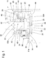
- the Figures 1 to 7 show several pneumatic actuators with different variants of shielding.
- a pneumatic actuator 10 is shown in the figure 1 .
- the pneumatic actuating device 10 is of essentially rotationally symmetrical design, as are a large part of the components formed on the actuating device 10 .
- the pneumatic actuating device 10 has a housing 12 and a working piston 14 .
- the housing 12 is also designed in several parts and includes a working cylinder 16 and a guide tube 18 firmly connected to the working cylinder 16.
- the guide tube 18 is pressed onto the working cylinder 16 and welded to it in an airtight manner.
- the working piston 14 is designed to be axially movable relative to the housing 12 , the working piston 14 and the housing 12 enclosing a pressure chamber 20 .
- the pressure chamber 20 can be filled with a pneumatic pressure medium, so that the working piston 14 moves axially relative to the housing 12 and actuates a friction clutch, not shown.
- the working piston 14 is designed in several parts. This includes a main piston 22 and an actuating piston 24, both of which are also referred to as partial pistons.
- the main piston 22 is designed in one piece and is guided relative to the actuating piston 24 and can be supported relative to it.
- the main piston 22 provides a guide in the form of a guide surface 22a for the actuating piston 24, against which the actuating piston 24 can also be supported.
- Sliding elements 26 are arranged on the main piston 22 within circumferential grooves, which enable low-friction axial mobility relative to the guide tube 18 .
- Sealing elements 28 are formed on the main piston 22 to seal off the pressure chamber 20 .
- the sealing elements 28 are arranged in circular circumferential grooves of the main piston 22 .
- One of the sealing elements is arranged radially on the outside of the main piston 22 and is in contact with the working cylinder 16 of the housing 12, the other sealing element 28 being arranged radially on the inside and being in connection with the guide tube 18 of the housing.
- the actuating piston 24 is designed in multiple parts and has, among other things, a flange 30 extending in the radial direction and a tubular guide element 32 .
- the guide element 32 and the flange are firmly connected to one another, in particular by a press connection, which is additionally welded airtight.
- the actuating piston 24 is guided by the guide element 32, which runs along a guide surface 22a of the main piston.
- sliding elements 34 are arranged on the guide element 32 within circular circumferential grooves.
- the actuating piston 24 is free to move axially relative to the main piston in the axial direction.
- a release bearing 36 is formed on the actuating piston 24, which interacts with a membrane spring, not shown, of the friction clutch.
- a position sensor system for detecting the axial position of the working piston is arranged on the pneumatic actuating device 10, for example. This position sensor system is well known. In the 1 only a position sensor is shown, the position of which can be determined by sensor electronics, not shown
- a clamping device 38 is formed on the working piston 14, in particular between the main piston 22 and the actuating piston 24, a clamping device 38 is formed. During an actuation process of the actuation device, this clamping device 38 ensures a fixation between the main piston 22 and the actuating piston 24. As a result, the working piston is fixed in its effective length during the actuation process. Upon completion of the actuation process, the fixation between the main piston 22 and the actuating piston 24 is released again by the clamping device, so that the partial pistons can again move freely in relation to one another. As a result, the working piston 14 adapts its effective length to the increasing wear of the friction clutch.
- the clamping device 38 includes, among other things, an actuating element 40, a plurality of clamping bodies 42 arranged in two rows in the circumferential direction, a clamping element 44 and a cage element 46.
- the actuating element 40 is firmly connected to the actuating piston 24 and engages in a clamping element 44 or, if necessary, through it.
- the clamping element is firmly connected to the main piston 22 .
- the clamping bodies 42 for example in the form of balls, cylindrical rollers or barrels, are arranged in two rows and distributed evenly along the circumference.
- the clamping device 38 can also be designed with a single row of clamping bodies. a single-row variant is also possible.
- the cage element 46 ensures that the free mobility of the clamping bodies 42 is limited to a space between the actuating element 40 and the clamping element 44 .
- the actuating element 40 and the clamping element 44 likewise carry out a relative movement.
- a conical clamping surface of the clamping element is moved towards the clamping body, with clamping body 42 being held in place due to an axial stop, so that clamping body 42 is clamped between actuating element 40 and clamping element 44 and the free axial mobility between partial pistons 22, 24 is thereby fixed.
- the cage element 46 Upon completion of the actuation process, the cage element 46 makes contact with the housing 12 and transmits this stop to the clamping body 42, so that it is released from the clamp and free mobility between the partial pistons 22, 24 is restored.
- the pneumatic actuating device 10 also has a spring element 48 which pretensions the actuating element 24 in relation to the friction clutch, in particular the diaphragm spring, and thereby ensures the correct effective length of the working piston 14 .
- a plurality of shielding elements 50, 51 are formed on the pneumatic actuating device 10.
- the shielding elements 50, 51 are each fixed to two components of the pneumatic actuating device 10.
- the radially outer shielding element 50 is fixed on the one hand to the clamping device 38, in particular to the cage element 46, and on the other hand to the flange 30 of the actuating piston 24.
- the shielding element 50 designed as a bellows surrounds the flange 38 radially on the outside and is fastened to the flange 30 by a section 50a pointing radially inwards and running around in the circumferential direction.
- the radially outer shielding element 50 is secured to the clamping device 38 by a securing element designed as a clamping ring 52 .
- the shielding element 51 located in a radially inner region of the pneumatic actuating device is fixed on the one hand indirectly via a support element 54 to the guide tube 18 of the housing 12 and on the other hand via a clamping ring 56 to the guide element 32 of the actuating piston 24.
- the support element 54 engages in a circular circumferential groove formed radially on the outside of the guide tube 18 .
- the support element 54 is captively attached to the housing 12 .
- a ramp which widens radially towards the groove is formed on the guide tube 18 .
- the support element 54 is simply pushed onto the guide tube.
- the support element 54 can be slotted for this purpose.
- the shielding element 50 has a U-shaped receptacle 51a, which encompasses the support element 54 over the entire circumference and is thereby captively attached to it.
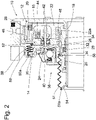
- the bellows 50 and 51 are elastic and can compensate for an axial movement of the components relative to one another by deformation. This is shown in figure 2 , which the pneumatic actuator 10 from figure 1 shows, but with a worn friction clutch. In addition, the bellows can also compensate for a relative movement during an actuation process in order to provide a permanent dirt shield.
- FIG 3 is essentially the same pneumatic actuator 10 as in FIG figure 1 and 2 shown. This differs only with regard to the shielding elements 50. Reference numbers for identical components have accordingly been adopted from the previous figures.
- the shielding element 51 is replaced by two shielding elements 58 and 60 .
- the shielding element 58 is arranged indirectly on the guide tube 18 on the one hand and is connected directly to the main piston 22 on the other hand.
- the design of the attachment is identical to that of the shielding element 51.
- the shielding element 58 is now attached to the main piston 22 and not to the actuating piston 24.
- the shielding element 58 is designed as a bellows.
- the further shielding element 60 is arranged on the one hand on the main piston 22 and on the other hand on the guide element 32 of the actuating piston 24 .
- This shielding element 60 is designed as a rolling bellows, which can roll up or down in the axial direction in order to permanently provide a dirt shield in the event of an axial relative movement between the partial pistons 22 , 24 .
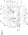
- the figure 4 shows a further modification of the pneumatic actuator 10 based on figure 3 .
- the shielding element 60 is replaced by the shielding element 64 .
- This shielding element 64 is formed by a bellows.
- the shielding element 64 is arranged on the actuating piston 22, in particular on the guide element 32, via a clamping ring.
- the shielding element 64 is directly on the housing 12, in particular on a further support element 66 which is firmly connected to the guide tube 18.
- a multi-stage shielding is provided, which makes it even more difficult for dirt to penetrate, in particular into the space between the guide tube and the main piston.
- the radially inner shielding element 68 is formed by a telescopic sleeve 68 .
- the telescopic sleeve consists of three plastic sleeves 74, 76 and 78 formed, which can move in the axial direction against each other. Stops 74a, 76a and 76b as well as 78a are formed on the plastic sleeves, which run around in the circumferential direction, undercut one another and thereby enable captive attachment to one another.
- a stop 74b is formed on the plastic sleeve 74, which engages in a circumferential groove on the housing 12, in particular the guide tube 18.
- the plastic sleeve 78 has a section 78b on the main piston side, which also engages in a circumferential groove of the main piston 22 .
- the plastic sleeve 78 is captively secured and can still perform a telescopic movement in relation to the main piston 22 .
- the groove 22b is made correspondingly longer in the axial direction than a width of the section.
- the radially outer shielding element 80 is formed by a plastic sleeve which is fastened to a groove of the actuating piston 24 via a snap connection. This shielding element 80 only has to be pushed on for attachment. A felt is formed on the housing side, which runs along the housing 12 in a dirt-repellent manner.
- the figure 7 shows a section of a pneumatic actuating device 10, specifically the radially outer shielding element 70.
- the rest of the structure is the same as in FIG figure 1 .
- the shielding element 70 is in the form of a bellows which is fixed on the one hand to the flange 30 and on the other hand to the working cylinder 16 of the housing 12 .
- the shielding element 70 is fixed on the housing side via a clamping ring 72 . With such a construction, the space of the clamping device 38 as well as the dirt shielding for the pressure chamber are taken over by a single shielding element 70 .
Landscapes
- Engineering & Computer Science (AREA)
- General Engineering & Computer Science (AREA)
- Mechanical Engineering (AREA)
- Actuator (AREA)
- Hydraulic Clutches, Magnetic Clutches, Fluid Clutches, And Fluid Joints (AREA)
Description
- Die Erfindung betrifft eine Betätigungseinrichtung mit einer Schmutzabschirmung. Aus dem Stand der Technik sind Betätigungseinrichtungen bekannt, die einen Verschleißausgleich aufweisen. Ein solcher Verschleißausgleich weist zumeist eine komplexe Mechanik auf. Diese Mechanik muss zur Gewährleistung der Verschleißausgleichsfunktion über die gesamte Lebensdauer besonders gut vor eindringendem Schmutz bewahrt werden.
-
DE 299 14 060 U1 ,DE 602 11 170 T2 undDE 693 06 098 T2 zeigen aus dem Stand der Technik bekannte Betätigungseinrichtungen für ein Kraftfahrzeug. - Es ist daher Aufgabe eine Betätigungseinrichtung bereitzustellen, die vor eindringendem Schmutz besonders gut geschützt ist.
- Die vorstehende Aufgabe wird gelöst durch eine Betätigungseinrichtung für ein Kraftfahrzeug gemäß dem Patentanspruch 1. In den abhängigen Patentansprüchen sind vorteilhafte Ausführungsvarianten der Betätigungseinrichtung dargestellt.
- Die Betätigungseinrichtung ist für ein Kraftfahrzeug geeignet, insbesondere für ein Nutzkraftfahrzeug. Zudem ist die Betätigungseinrichtung als pneumatische Betätigungseinrichtung ausgebildet. Die Betätigungseinrichtung umfasst ein Gehäuse, welches einteilig oder mehrteilig, beispielsweise aus einem Arbeitszylinder und einem fest mit diesem verbundenen Führungsrohr, ausgebildet ist. Des Weiteren ist an der Betätigungseinrichtung ein mehrteiliger Arbeitskolben ausgebildet, der sich axial gegenüber dem Gehäuse verschieben kann.
- Das Gehäuse und der Arbeitskolben umschließen einen Druckraum, der mit einem Druckmedium gefüllt werden kann, um eine Kupplung durch ein axiales Ausrücken des Arbeitskolbens gegenüber dem Gehäuse zu betätigen. Dieser Arbeitsraum ist bei einem pneumatischen System vorteilhafterweise mit einem sehr geringen Arbeitsvolumen ausgebildet. Dies ist begründet in der Kompressibilität des pneumatischen Druckmediums. Durch ein geringes Arbeitsvolumen wird dementsprechend ein schnelles und komfortables Betätigen der Kupplung ermöglicht. Ein kleines Arbeitsvolumen wird durch die Verwendung eines mehrteiligen Arbeitskolbens ermöglicht. Ein solcher mehrteiliger Arbeitskolben weist unter anderem einen Hauptkolben sowie einen Stellkolben aufweist, die für eine Verschleißausgleichfunktion axial beweglich zueinander ausgebildet sind. Ein an einer Reibungskupplung auftretender Verschleiß macht sich an eine Reibungskupplung durch eine abnehmende Belagdicke bemerkbar. Bei eine Reibungskupplung wird üblicherweise eine Membranfeder verwendet, deren Membranfederzungen sich mit ansteigendem Verschleiß der Kupplung in axialer Richtung auf die pneumatische Betätigungseinrichtung zu bewegen. Durch die axiale Beweglichkeit von Stellkolben zu Hauptkolben kann der Stellkolben der Bewegung der Membranfederzungen folgen und in den Hauptkolben einfahren und dadurch den Verschleiß der Reibungskupplung ausgleichen. Durch die membranfedergeführte Relativbewegung zwischen Stellkolben und Hauptkolben stellt sich an dem Arbeitskolben die korrekte Wirklänge ein. Zur Gewährleistung eines dauerhaften Anlagekontakts zwischen Stellkolben und Membranfeder, insbesondere über ein Ausrücklager, ist der Stellkolben gegenüber der Membranfeder in axialer Richtung vorgespannt, beispielsweise durch ein Federelement zwischen Stellkolben und Hauptkolben. Zwischen dem Hauptkolben und dem Stellkolben ist so viel Platz vorhanden, so dass der Stellkolben die Verschleißausgleichbewegung über dem gesamten Verschleißweg der Kupplung nachführen kann.
- An der Betätigungseinrichtung ist zudem eine Klemmeinrichtung ausgebildet, die die eine Relativbewegung zwischen Hauptkolben und Stellkolben während eines Betätigungsvorgangs verhindert. Diese Klemmeinrichtung stellt einen Klemmmechanismus bereit, der während eines Betätigungsvorgangs eine Fixierung zwischen Hauptkolben und Stellkolben bewirkt, so dass die axiale Position zwischen Hauptkolben und Stellkolben und damit auch die Wirklänge des Arbeitskolbens während des Betätigungsvorgangs unverändert bleibt. Mit Abschluss des Betätigungsvorgangs wird die Fixierung wieder freigegeben, sodass der Hauptkolben und der Stellkolben wieder eine entsprechende Ausgleichsbewegung zueinander durchführen können.
- Eine solche Klemmeinrichtung ist beispielsweise durch eine Mechanik ausgebildet, die zwischen dem Hauptkolben und dem Stellkolben angeordnet ist. Diese befindet sich nicht innerhalb des Arbeitsraums, der über Dichtungen von einer Umgebung abgeschirmt ist.
- Demnach ist an der Betätigungseinrichtung ein Abschirmelement zum Schutz der Betätigungseinrichtung vor Schmutz ausgebildet. Dieses Abschirmelement ist vorteilhafterweise an zwei Bauteilen der pneumatischen Betätigungseinrichtung angeordnet, insbesondere befestigt. Das Abschirmelement erstreckt sich entsprechend von dem ersten zu dem zweiten Bauteil und schirmt den umschlossenen Bereich von eindringendem Schmutz ab.
- Das Abschirmelement in seiner Länge vorteilhafterweise variabel ausgebildet, um eine Relativbewegung der Bauteile ausgleichen zu können und trotzdem jederzeit die Schmutzabschirmfunktion gewährleisten zu können.
- In einer allgemeineren Variante ist das Abschirmelement zwischen dem Gehäuse und einem Teilkolben des Arbeitskolbens, also dem Stellkolben oder dem Hauptkolben, angeordnet. Für den Aufbau des Arbeitskolbens durch einen Stellkolben und einen Hauptkolben gibt es verschiedene Ausführungsvarianten, die alle hierunter fallen. Die verschiedenen Ausgestaltungsvarianten des Arbeitskolbens unterscheiden sich unter anderem in der Anordnung der Gleitflächen, also welcher Teilkolben an dem Gehäuse gleitet oder welcher Teilkolben an einem anderen Teilkolben gleitet.
- Das Abschirmelement kann insbesondere zwischen dem Gehäuse und dem Hauptkolben angeordnet sein. Gehäuseseitig ist das Abschirmelement günstigerweise an einem Führungsrohr angeordnet. Diese Anordnung deckt insbesondere einen radial innenliegenden Bereich ab und schützt insbesondere Gleitflächen der Kolben vor eindringendem Schmutz. Alternativ oder zusätzlich kann eine Anordnung zwischen Gehäuse und Arbeitszylinder einen radial Außenliegenden Bereich der Betätigungseinrichtung vor Schmutz abschirmen, insbesondere die Klemmeinrichtung.
- In einer anderen Variante ist das Abschirmelement zwischen dem Gehäuse und dem Stellkolben angeordnet. Auch hier ist eine gehäuseseitige Anordnung an einem Führungsrohr vorteilhaft.
- In einer weiteren Grundsätzlichen Anordnungsvarianten kann das Abschirmelement an zwei Teilkolben, insbesondere dem Hauptkolben und dem Stellkolben, angeordnet sein. Hierdurch wird insbesondere eine Gleitfläche zwischen zwei Teilkolben vor eindringendem Schmutz geschützt.
- Es ist auch Vorteilhaft, wenn das Abschirmelement einerseits an einem Teilkolben, insbesondere dem Stellkolben und andererseits an einem Element der Klemmeinrichtung angeordnet ist. Dadurch lassen sich der radial äußere Bereich der Betätigungseinrichtung und insbesondere die Klemmeinrichtung optimal vor Verschmutzung schützen.
- Die Anordnung des Abschirmelements an den genannten Bauteilen kann unmittelbar oder auch mittelbar also über ein Zwischenbauteil erfolgen. An der Betätigungseinrichtung können auch mehrere der erläuterten Varianten gleichzeitig ausgeführt sein.
- Durch die Verwendung eines oder mehrerer Abschirmelemente an der Betätigungseinrichtung wird eine gute Schmutzabschirmung erreicht, die eine Lebensdauer des Verschleißmechanismus über die gesamte Lebensdauer der Reibungskupplung ermöglicht.
- Im Weiteren werden vorteilhafte Ausführungsvarianten der Betätigungseinrichtung erläutert.
- Es wird vorgeschlagen, dass das Abschirmelement als Faltenbalg, als Rollbalg oder als Teleskophülse ausgebildet ist.
- Der Faltenbalg stellt ein elastisches Abschirmelement bereit, welches sich der axialen Bewegung zwischen zwei Bauteilen durch elastische Verformung anpasst und durch seine Schmutzundurchlässigkeit eine dauerhafte Schmutzabschirmung bereitstellt.
- Der Rollbalg hat eine ähnliche Wirkungsweise wie ein Faltenbalg. Anstelle des Zieharmonikaeffekts drückt sich die elastisch Verformung durch Aufrollen und Abrollen des Faltenbalgs aus. Der Rollbalg rollt sich entsprechend der axialen vorgegebenen Bewegung zwischen den beiden Bauteilen auf oder ab. Günstigerweise ist eine Rollfläche ausgebildet, an er sich der Rollbalg anlegen und abrollen kann.
- Die Teleskophülse kann beispielsweise durch ein oder mehrere Hülsen ausgebildet sein, die jeweils für sich formstabil sind. Eine Teleskophülse weist entsprechend eine oder mehrere Hülsen auf, die auf einem benachbarten Bauteil oder auf einer benachbarten Hülse gleiten können. Die Hülsen verschieben sich gegeneinander um durch eine teleskopartige Bewegung eine ununterbrochene Schmutzabschirmung bereitzustellen. Die Hülsen weisen entsprechende Anschläge auf, die mit einer benachbarten Hülse oder einem Bauteil verliersicher in einander eingreifen. Die Hülsen können also nicht auseinanderfallen. Mit besonderem Vorteil sind an einer Teleskophülse zwei oder mehr Hülsen verwendet, wobei die erste und die letzte Hülse vorzugsweise verliersicher und fest mit einem jeweiligen Bauteil der Betätigungseinrichtung verbunden sind.
- In einer vorteilhaften Ausführungsvariante greift das Abschirmelement an dem jeweiligen Bauteil in eine Sicherungsform ein.
- Eine solche Sicherungsform kann beispielsweise eine Nut sein, in die beispielsweise eine Teleskophülse, insbesondere eine Hülse der Teleskophülse einschnappt. Diese Nut ist beispielhaft in ein Führungsrohr oder in einen Stellkolben eingebracht, vorzugsweise vollständig umlaufend. Die Hülse wird mit deren Anschlag auf das jeweilige Bauteil aufgeschoben, bis es in die Sicherungsform, in diesem Fall also die Nut, einschnappt. Dadurch ist eine verliersichere Befestigung des Abschirmelements gewährleistet. Es kann beispielsweise auch ein Endabschnitt eines Rollbalgs oder eines Faltenbalgs an oder innerhalb einer solchen Sicherungsform angeordnet sein, beispielsweise ebenfalls einer umlaufenden Nut.
- Günstiger Weise ist an einem Bauteil ein Stützelement angeordnet, an dem das Abschirmelement verliersicher angeordnet ist.
- Ein Bauteil kann jedes Bauteil der Betätigungseinrichtung sein, vorzugsweise ein Teilkolben, das Gehäuse oder auch ein Bauteil der Klemmeinrichtung. Das Stützelement stellt dementsprechend eine mittelbare Anordnung des Abschirmelements an dem Bauteil bereit. Hierdurch kann zumeist eine einfachere Geometrie oder Ausführungsvariante des Abschirmelements gewählt werden und dennoch eine sichere Befestigung an dem gewünschten Bauteil erreicht werden. Das Stützelement kann zur Befestigung an dem jeweiligen Bauteil beispielsweise in eine Sicherungsform eingreifen, die in den vorherigen Abschnitten ausführlich erläutert wurde. Vorzugsweise ist das Stützelement an einer umlaufenden Nut des Bauteils befestigt.
- In einer anderen Ausgestaltungsvariante ist das Abschirmelement über ein Sicherungselement verliersicher an dem jeweiligen Bauteil befestigt.
- Durch das Sicherungselement ist eine dauerhafte Schmutzabschirmung gewährleistet. Ein solches Sicherungselement kann beispielsweise als Spannring ausgebildet sein, der an einem Balg zur Anlage kommt und diesen gegenüber dem Bauteil festdrückt. Alternativ kann das Sicherungselement auch durch einen Sicherungsring bereitgestellt sein, der in eine umlaufende Nut eingreift und dadurch eine axiale Bewegung des Abschirmelements über den Sicherungsring hinaus verhindert.
- In einer besonders vorteilhaften Ausführungsvariante ist die Teleskophülse durch mehrere Kunststoffhülsen ausgebildet.
- Die Kunststoffhülsen sind diese günstig herzustellen und weisen eine ausreichende Formstabilität und sind zudem Schmutzundurchlässig.
- Die Betätigungseinrichtung mit Schmutzabschirmung wird im Weiteren beispielhaft und ausführlich anhand mehrerer Figuren erläutert.
- Die
Figuren 1 bis 7 zeigen mehrere pneumatische Betätigungseinrichtungen mit verschiedenen Varianten von Abschirmelementen. - In der
Figur 1 ist eine pneumatische Betätigungseinrichtung 10 dargestellt. Die pneumatische Betätigungseinrichtung 10 ist im Wesentlichen rotationssymmetrisch ausgebildet, so wie auch ein Großteil der an der Betätigungseinrichtung 10 ausgebildeten Bauteile. - Die pneumatische Betätigungseinrichtung 10 weist ein Gehäuse 12 sowie einen Arbeitskolben 14 auf. Auch das Gehäuse 12 ist mehrteilig ausgebildet und umfasst einen Arbeitszylinder 16 sowie ein fest mit dem Arbeitszylinder 16 verbundenes Führungsrohr 18. Das Führungsrohr 18 ist auf den Arbeitszylinder 16 aufgepresst und luftdicht mit diesen verschweißt.
- Der Arbeitskolben 14 ist axial beweglich gegenüber dem Gehäuse 12 ausgeführt, wobei der Arbeitskolben 14 und das Gehäuse 12 einen Druckraum 20 umschließen. Der Druckraum 20 kann mit einem pneumatischen Druckmedium gefüllt werden, sodass sich der Arbeitskolben 14 axial gegenüber dem Gehäuse 12 bewegt und eine nicht dargestellte Reibungskupplung betätigt.
- Zudem ist der Arbeitskolben 14 ist mehrteilig ausgeführt. Dieser umfasst einen Hauptkolben 22 sowie einen Stellkolben 24, die beide auch als Teilkolben bezeichnet werden. Der Hauptkolben 22 ist einteilig ausgeführt und ist gegenüber dem Stellkolben 24 geführt und kann sich gegenüber diesem abstützen. Außerdem stellt der Hauptkolben 22 eine Führung in Form einer Führungsfläche 22a für den Stellkolben 24 bereit, gegenüber der sich der Stellkolben 24 auch abstützen kann. An dem Hauptkolben 22 sind innerhalb von umlaufenden Nuten Gleitelement 26 angeordnet, die eine reibungsarme axiale Beweglichkeit gegenüber dem Führungsrohr 18 ermöglichen.
- Zur Abdichtung des Druckraums 20 sind an dem Hauptkolben 22 Dichtelemente 28 ausgebildet. Die Dichtelement 28 sind in kreisförmig umlaufenden Nuten des Hauptkolbens 22 angeordnet. Eines der Dichtelemente ist radial außen an dem Hauptkolben 22 angeordnet und steht mit dem Arbeitszylinder 16 des Gehäuses 12 in Anlagekontakt, wobei das andere Dichtelement 28 radial innen angeordnet ist und mit dem Führungsrohr 18 des Gehäuses in Verbindung steht.
- Der Stellkolben 24 ist mehrteilig ausgeführt und weist unter anderem einen sich in radialer Richtung erstreckenden Flansch 30 sowie ein rohrförmig ausgebildetes Führungselement 32 auf. Das Führungselement 32 und der Flansch sind fest miteinander verbunden, insbesondere durch eine Pressverbindung, die zusätzlich luftdicht verschweißt ist.
- Der Stellkolben 24 wird durch das Führungselement 32 geführt, welches läuft auf einer Führungsfläche 22a des Hauptkolbens entlangleiten kann. Hierfür sind an dem Führungselement 32 Gleitelemente 34 innerhalb von kreisförmig umlaufenden Nuten angeordnet. Der Stellkolben 24 kann sich axial frei gegenüber dem Hauptkolben in axialer Richtung bewegen.
- Zudem ist an dem Stellkolben 24 ein Ausrücklager 36 ausgebildet, welches mit einer nicht dargestellten Membranfeder der Reibungskupplung zusammenwirkt. Zudem ist an der pneumatischen Betätigungseinrichtung 10 beispielhaft eine Positionssensorik zur Erfassung der Axialposition des Arbeitskolbens angeordnet. Diese Positionssensorik ist hinreichend bekannt. In der
Fig. 1 ist lediglich ein Positionsgeber dargestellt, dessen Position durch eine nicht dargestellte Sensorelektronik ermittelt werden kann - An dem Arbeitskolben 14, insbesondere zwischen dem Hauptkolben 22 und dem Stellkolben 24, ist eine Klemmeinrichtung 38 ausgebildet. Diese Klemmeinrichtung 38 sorgt während eines Betätigungsvorgangs der Betätigungseinrichtung für eine Fixierung zwischen Hauptkolben 22 und Stellkolben 24. Dadurch ist der Arbeitskolben während des Betätigungsvorgangs in seiner Wirklänge festgelegt. Mit Abschluss des Betätigungsvorgangs wird die Fixierung zwischen Hauptkolben 22 und Stellkolben 24 durch die Klemmeinrichtung wieder aufgehoben, so dass sich die Teilkolben wieder frei gegeneinander bewegen können. Der Arbeitskolben 14 passt dadurch seine Wirklänge dem ansteigendem Verschleiß der Reibungskupplung an.
- Die Klemmeinrichtung 38 umfasst unter anderem ein Stellelement 40, mehrere zweireihig in Umfangsrichtung angeordnete Klemmkörper 42, ein Klemmelement 44 sowie ein Käfigelement 46.
- Das Stellelement 40 ist fest mit dem Stellkolben 24 verbunden und greift in ein Klemmelement 44 ein oder gegebenenfalls durch dieses hindurch. Das Klemmelement ist fest mit dem Hauptkolben 22 verbunden. Zwischen dem Stellelement 40 und dem Klemmelement sind die Klemmkörper 42, beispielsweise in Form von Kugeln, Zylinderrollen oder Tonnen, in zwei Reihen angeordnet und gleichmäßig am Umfang entlang verteilt. Die Klemmeinrichtung 38 kann auch mit einer einzigen Reihe von Klemmkörpern ausgeführt sein. ist auch eine einreihige Ausführungsvariante möglich. Das Käfigelement 46 sorgt dafür, dass die Klemmkörper 42 in derer freien Beweglichkeit auf einen Raum zwischen dem Stellelement 40 und dem Klemmelement 44 begrenzt sind.
- Bei einer axialen Bewegung zwischen Hauptkolben 22 und Stellkolben 24 führen das Stellelement 40 und das Klemmelement 44 ebenfalls eine Relativbewegung aus. Dadurch wird ein konische Klemmfläche des Klemmelements auf den Klemmkörper hinzubewegt, wobei der Klemmkörper 42 aufgrund eines axialen Anschlags festgehalten wird, sodass der Klemmkörper 42 zwischen Stellelement 40 und Klemmelement 44 eingeklemmt wird und dadurch die freie axiale Beweglichkeit zwischen den Teilkolben 22, 24 fixiert wird.
- Mit Abschluss des Betätigungsvorgangs stellt das Käfigelement 46 einen Anlagekontakt mit dem Gehäuse 12 her und gibt diesen Anschlag an den Klemmkörper 42 weiter, sodass dieser aus er Klemmung gelöst wird und die freie Beweglichkeit zwischen den Teilkolben 22, 24 wieder hergestellt ist.
- Die pneumatischen Betätigungseinrichtung 10 weist zudem ein Federelement 48 auf, welches das Stellelement 24 gegenüber der Reibungskupplung, insbesondere der Membranfeder, vorspannt und dadurch für die korrekte Wirklänge des Arbeitskolbens 14 sorgt.
- Des Weiteren sind an der pneumatischen Betätigungseinrichtung 10 mehrere Abschirmelemente 50, 51 ausgebildet. Die Abschirmelemente 50, 51 sind jeweils an zwei Bauteilen der pneumatischen Betätigungseinrichtung 10 festgelegt.
- Das radial äußere Abschirmelement 50 ist einerseits an der Klemmeinrichtung 38, insbesondere an dem Käfigelement 46, und andererseits an dem Flansch 30 des Stellkolbens 24 festgelegt. Das als Faltenbalg ausgebildete Abschirmelement 50 umgreift den Flansch 38 radial außen und ist durch einen radial nach innen weisenden und in Umfangsrichtung umlaufenden Abschnitt 50a an dem Flansch 30 befestigt. Klemmelementseitig ist das radial außen liegende Abschirmelement 50 durch einen als Spannring 52 ausgebildetes Sicherungselement an der Klemmeinrichtung 38 gesichert.
- Das in einem radial inneren Bereich der pneumatischen Betätigungseinrichtung liegende Abschirmelement 51 ist einerseits mittelbar über ein Stützelement 54 an dem Führungsrohr 18 des Gehäuses 12 und andererseits über einen Spannring 56 an dem Führungselement 32 des Stellkolbens 24 festgelegt.
- Das Stützelement 54 greift in eine radial außen an dem Führungsrohr 18 ausgeführte kreisförmig umlaufende Nut ein. Dadurch ist das Stützelement 54 verliersicher an dem Gehäuse 12 befestigt. Zur leichteren Montage ist an dem Führungsrohr 18 eine sich zur Nut hin radial aufweitende Rampe ausgebildet. Das Stützelement 54 wird einfach auf das Führungsrohr aufgeschoben. Optional kann das Stützelement 54 dafür geschlitzt ausgebildet sein.
- Das Abschirmelement 50 weist eine u-förmige Aufnahme 51a auf, die das Stützelement 54 über den gesamten Umfang umgreift und dadurch verliersicher an diesem befestigt ist.
- Die Faltenbalge 50 und 51 sind elastisch und können durch Verformung eine axiale Bewegung der Bauteile zueinander ausgleichen. Gezeigt ist dies in
Figur 2 , die die pneumatische Betätigungseinrichtung 10 ausFigur 1 darstellt, jedoch bei verschlissener Reibungskupplung. Die Faltenbalge können zudem auch eine Relativbewegung während eines Betätigungsvorgangs ausgleichen, um eine dauerhafte Schmutzabschirmung bereitzustellen. - In der
Figur 3 ist im Wesentlichen dieselbe pneumatische Betätigungseinrichtung 10 wie inFigur 1 und2 dargestellt. Diese unterscheidet sich lediglich bezüglich der Abschirmelemente 50. Bezugszeichen für identische Bauteile wurden dementsprechend aus den vorigen Figuren übernommen. - Das Abschirmelement 51 ist durch zwei Abschirmelemente 58 und 60 ersetzt. Das Abschirmelement 58 ist einerseits mittelbar an dem Führungsrohr 18 angeordnet und andererseits direkt mit dem Hauptkolben 22 verbunden. Die Ausführung der Befestigung ist identisch zu dem des Abschirmelements 51. Allerdings ist das Abschirmelement 58 nun an dem Hauptkolben 22 und nicht an dem Stellkolben 24 befestigt. Das Abschirmelement 58 ist wie auch das Abschirmelement 51 als Faltenbalg ausgebildet.
- Das weitere Abschirmelement 60 ist einerseits an dem Hauptkolben 22 und andererseits an dem Führungselement 32 des Stellkolbens 24 angeordnet. Dieses Abschirmelement 60 ist hierbei als Rollbalg ausgeführt, der sich entsprechend in axialer Richtung ab- oder aufrollen kann, um eine Schmutzabschirmung bei einer axialen Relativbewegung zwischen dem Teilkolben 22, 24 dauerhaft bereitzustellen.
- Die
Figur 4 zeigt eine weitere Abwandlung der pneumatischen Betätigungseinrichtung 10 ausgehend vonFigur 3 . Hierbei ist das Abschirmelement 60 durch das Abschirmelement 64 ersetzt. Dieses Abschirmelement 64 ist durch einen Faltenbalg ausgebildet. Einerseits ist das Abschirmelement 64 an dem Stellkolben 22, insbesondere an dem Führungselement 32 über einen Spannring angeordnet. Andererseits ist das Abschirmelement 64 mittelbar an dem Gehäuse 12, insbesondere an einem weiteren Stützelement 66, welches fest mit dem Führungsrohr 18 verbunden ist. Hierdurch wird eine mehrstufige Abschirmung bereitgestellt, die ein Eindringen von Schmutz, insbesondere in den Raum zwischen Führungsrohr und Hauptkolben nochmals wesentlich erschwert. - Eine weitere Ausführungsvariante ist in der
Figur 5 und in einer dazugehörigen vergrößerten Darstellung nachFigur 6 gezeigt. Das radial innere Abschirmelement 68 ist durch eine Teleskophülse 68 ausgebildet. Die Teleskophülse ist aus drei Kunststoffhülsen 74, 76 und 78 ausgebildet, die sich in axialer Richtung gegeneinander verschieben können. An den Kunststoffhülsen sind Anschläge 74a, 76a und 76b sowie 78a ausgebildet, die in Umfangsrichtung umlaufen, einander hinterschneiden und dadurch eine verliersichere Befestigung aneinander ermöglichen. Zudem ist an der Kunststoffhülse 74 ein Anschlag 74b ausgebildet, der an dem Gehäuse 12, insbesondere dem Führungsrohr 18, in eine umlaufende Nut eingreift. Die erste Kunststoffhülse 74 ist dadurch fest mit dem Gehäuse 12 verbunden. Die Kunststoffhülse 78 weist einen hauptkolbenseitigen Abschnitt 78b auf, der ebenfalls in eine umlaufende Nut des Hauptkolbens 22 eingreift. Hierdurch ist die Kunststoffhülse 78 verliersicher befestigt und kann trotzdem noch eine Teleskopbewegung gegenüber dem Hauptkolben 22 ausführen. Die Nut 22b ist in axialer Richtung entsprechend länger ausgeführt als eine Breite des Abschnitts. - Das radial äußere Abschirmelement 80 ist durch eine Kuststoffhülse ausgebildet, die über eine Schnappverbindung an einer Nut des Stellkolbens 24 befestigt ist. Dieses Abschirmelement 80 muss zur Befestigung lediglich aufgeschoben werden. Gehäuseseitig ist ein Filz ausgebildet, der an dem Gehäuse 12 schmutzabweisend entlangläuft.
- Die
Figur 7 zeigt einen Ausschnitt eine pneumatische Betätigungseinrichtung 10 und zwar das radial äußere Abschirmelement 70. Der restliche Aufbau gleich dem ausFigur 1 . Das Abschirmelement 70 ist in Form eines Faltenbalgs ausgebildet, der einerseits an dem Flansch 30 und andererseits an dem Arbeitszylinder 16 des Gehäuses 12 festgelegt ist. Das Abschirmelement 70 ist gehäuseseitig über einen Spannring 72 festgelegt. Durch einen derartigen Aufbau wird einerseits der Raum der Klemmeinrichtung 38 sowie auch die Schmutzabschirmung für den Druckraum durch ein einziges Abschirmelement 70 übernommen. -
- 10
- pneumatische Betätigungseinrichtung
- 12
- Gehäuse
- 14
- Arbeitskolben
- 16
- Arbeitszylinder
- 18
- Führungsrohr
- 20
- Druckraum
- 22
- Hauptkolben
- 22a
- Führungsfläche
- 22b
- Nut
- 24
- Stellkolben
- 26
- Gleitelement
- 28
- Dichtelement
- 30
- Flansch
- 32
- Führungselement
- 34
- Gleitelement
- 36
- Ausrücklager
- 38
- Klemmeinrichtung
- 40
- Stellelement
- 42
- Klemmkörper
- 44
- Klemmelement
- 46
- Käfigelement
- 48
- Federelement
- 50
- Abschirmelement
- 50a
- Abschnitt
- 51
- Abschirmelement
- 51a
- u-förmige Aufnahme
- 52
- Spannring
- 54
- Stützelement
- 56
- Spannring
- 58
- Abschirmelement
- 60
- Abschirmelement
- 64
- Abschirmelement
- 66
- Stützelement
- 68
- Teleskophülse
- 70
- Abschirmelement
- 72
- Spannring
- 74
- Kunststoffhülse
- 74a
- Anschlag
- 74b
- Anschlag
- 76
- Kunststoffhülse
- 76a
- Anschlag
- 76b
- Anschlag
- 78
- Kunststoffhülse
- 78a
- Anschlag
- 78b
- Anschlag
- 80
- Abschirmelement
Claims (6)
- Betätigungseinrichtung (10) für ein Kraftfahrzeug, wobei die Betätigungseinrichtung als pneumatische Betätigungseinrichtung ausgebildet ist, umfassend- ein Gehäuse (12) und- einen gegenüber dem Gehäuse (12) beweglichen mehrteiligen Arbeitskolben (14), wobei- das Gehäuse (12) und der Arbeitskolben (14) einen Druckraum (20) umschließen, der mit einem Druckmedium (20) gefüllt werden kann, um ein axiales Ausrücken des Arbeitskolbens (14) gegenüber dem Gehäuse (12) zur Betätigung einer Kupplung bereitzustellen, wobei- der mehrteilige Arbeitskolben (14) einen Hauptkolben (22) und einen Stellkolben (24) aufweist, die für einen Verschleißausgleich axial beweglich zueinander ausgebildet sind,- wobei eine Klemmeinrichtung (38) den Hauptkolben (22) und den Stellkolben (24) zur Fixierung einer Wirklänge des Arbeitskolbens (14) gegeneinander verklemmen kann, wobei- an dem Stellkolben (24) ein Ausrücklager (36) ausgebildet ist, wobei- Hauptkolben (22) und Stellkolben (24) als Teilkolben (22, 24) des Arbeitskolbens (14) bezeichnet werden,- wobei ein Abschirmelement (50, 51,58, 60, 64 70, 80) zum Schutz der Betätigungseinrichtung (10) vor Schmutz• an dem Gehäuse (12) und an einem Teilkolben (22, 24) oder• an einem ersten Teilkolben (22, 24) und einem zweiten Teilkolben (22, 24) oder• an dem Stellkolben (22, 24) und an der Klemmeinrichtung (38) angeordnet ist.
- Betätigungseinrichtung (10) nach Anspruch 1, dadurch gekennzeichnet, dass das Abschirmelement als Faltenbalg, als Rollbalg oder als Teleskophülse ausgebildet ist.
- Betätigungseinrichtung (10) nach Anspruch 1 oder 2, dadurch gekennzeichnet, dass das Abschirmelement an dem jeweiligen Bauteil in eine Sicherungsform eingreift.
- Betätigungseinrichtung (10) nach einem der Ansprüche 1 bis 3, dadurch gekennzeichnet, dass an einem Bauteil ein Stützelement angeordnet ist, an dem das Abschirmelement verliersicher angeordnet ist.
- Betätigungseinrichtung (10) nach einem der Ansprüche 1 bis 4, dadurch gekennzeichnet, dass das Abschirmelement über ein Sicherungselement verliersicher an dem jeweiligen Bauteil befestigt ist.
- Betätigungseinrichtung (10) nach einem der Ansprüche 2 bis 5, dadurch gekennzeichnet, dass die Teleskophülse durch mehrere Kunststoffhülsen ausgebildet ist.
Applications Claiming Priority (2)
| Application Number | Priority Date | Filing Date | Title |
|---|---|---|---|
| DE102017218512.0A DE102017218512A1 (de) | 2017-10-17 | 2017-10-17 | Betätigungseinrichtung mit Schmutzabschirmung |
| PCT/EP2018/075260 WO2019076563A1 (de) | 2017-10-17 | 2018-09-19 | Betätigungseinrichtung mit schmutzabschirmung |
Publications (2)
| Publication Number | Publication Date |
|---|---|
| EP3698063A1 EP3698063A1 (de) | 2020-08-26 |
| EP3698063B1 true EP3698063B1 (de) | 2022-06-15 |
Family
ID=63685956
Family Applications (1)
| Application Number | Title | Priority Date | Filing Date |
|---|---|---|---|
| EP18778849.2A Active EP3698063B1 (de) | 2017-10-17 | 2018-09-19 | Betätigungseinrichtung mit schmutzabschirmung |
Country Status (5)
| Country | Link |
|---|---|
| US (1) | US11473632B2 (de) |
| EP (1) | EP3698063B1 (de) |
| CN (1) | CN111212986B (de) |
| DE (1) | DE102017218512A1 (de) |
| WO (1) | WO2019076563A1 (de) |
Families Citing this family (3)
| Publication number | Priority date | Publication date | Assignee | Title |
|---|---|---|---|---|
| CN110333265B (zh) * | 2019-07-11 | 2020-11-06 | 中国中车股份有限公司 | 一种预测机车发动机排气波纹管剩余寿命的方法及系统 |
| CN114483812B (zh) * | 2020-11-11 | 2025-08-05 | 克诺尔制动系统(大连)有限公司 | 离合器致动装置 |
| CN114483813B (zh) * | 2020-11-13 | 2025-06-24 | 克诺尔制动系统(大连)有限公司 | 用于操作离合器的自调节机构、离合器总成以及车辆 |
Family Cites Families (17)
| Publication number | Priority date | Publication date | Assignee | Title |
|---|---|---|---|---|
| US2971399A (en) | 1959-05-27 | 1961-02-14 | Mc Graw Edison Co | Telescopic protector |
| US3430744A (en) | 1967-09-22 | 1969-03-04 | Aisin Seiki | Clutch release motor with automatic compensator for disc wear |
| US3828894A (en) * | 1972-12-27 | 1974-08-13 | Goodyear Tire & Rubber | Telescopic piston for added brake wear adjustment |
| DE3136548A1 (de) * | 1981-09-15 | 1983-03-31 | LuK Lamellen und Kupplungsbau GmbH, 7580 Bühl | Druckmittelbetaetigte ausrueckvorrichtung fuer kupplungen, insbesondere fuer kraftfahrzeugkupplungen |
| DE3206873A1 (de) * | 1982-02-26 | 1983-09-15 | Fichtel & Sachs Ag, 8720 Schweinfurt | Hydraulisch betaetigbarer waelzlagerausruecker |
| US4617855A (en) * | 1984-08-15 | 1986-10-21 | Automotive Products Plc | Hydraulic slave cylinder switch |
| DE4100950C2 (de) * | 1991-01-15 | 1998-10-15 | Fte Automotive Gmbh | Hydraulische Kupplungsbetätigungseinrichtung |
| GB9205661D0 (en) | 1992-03-14 | 1992-04-29 | Eaton Corp | Self adjust clutch actuator |
| FR2695686B1 (fr) | 1992-09-17 | 1994-10-28 | Automotive Prod France | Cylindre asservi actionné par un moyen élastique pour embrayage hydraulique. |
| DE29914060U1 (de) * | 1999-08-12 | 2000-09-21 | Siemens AG, 80333 München | Elektromechanische Kraftfahrzeug-Bremsvorrichtung |
| US6389956B1 (en) * | 2000-03-21 | 2002-05-21 | Automotive Products, Inc. | Concentrically mounted hydraulic clutch slave cylinder |
| FR2826419B1 (fr) * | 2001-06-21 | 2005-01-28 | Bosch Gmbh Robert | Frein a disque pour vehicule a compensation d'usure des garnitures |
| DE102007032488A1 (de) * | 2006-08-09 | 2008-02-14 | Luk Lamellen Und Kupplungsbau Beteiligungs Kg | Einrichtung zur pneumatischen Betätigung einer Fahrzeugkupplung |
| DE102006050802B4 (de) * | 2006-10-27 | 2011-07-07 | Knorr-Bremse Systeme für Nutzfahrzeuge GmbH, 80809 | Kupplungsbetätigungsvorrichtung |
| DE102010011725A1 (de) * | 2010-03-17 | 2011-09-22 | Haldex Brake Products Ab | Scheibenbremse und Herstellungsverfahren für eine Scheibenbremse |
| DE102012212539A1 (de) * | 2012-07-18 | 2014-01-23 | Schaeffler Technologies AG & Co. KG | Ausrücklageranordnung |
| DE112014005189A5 (de) * | 2013-11-13 | 2016-07-21 | Schaeffler Technologies AG & Co. KG | Kupplungsaggregat |
-
2017
- 2017-10-17 DE DE102017218512.0A patent/DE102017218512A1/de active Pending
-
2018
- 2018-09-19 US US16/755,782 patent/US11473632B2/en active Active
- 2018-09-19 WO PCT/EP2018/075260 patent/WO2019076563A1/de not_active Ceased
- 2018-09-19 CN CN201880067314.XA patent/CN111212986B/zh active Active
- 2018-09-19 EP EP18778849.2A patent/EP3698063B1/de active Active
Also Published As
| Publication number | Publication date |
|---|---|
| US11473632B2 (en) | 2022-10-18 |
| WO2019076563A1 (de) | 2019-04-25 |
| EP3698063A1 (de) | 2020-08-26 |
| CN111212986A (zh) | 2020-05-29 |
| CN111212986B (zh) | 2022-02-01 |
| US20210190152A1 (en) | 2021-06-24 |
| DE102017218512A1 (de) | 2019-04-18 |
Similar Documents
| Publication | Publication Date | Title |
|---|---|---|
| EP0074671B1 (de) | Druckmittelbetätigte Ausrückvorrichtung für Kupplungen, insbesondere für Kraftfahrzeugkupplungen | |
| EP2427359B1 (de) | Zahnstangenlenkung | |
| EP2831441B1 (de) | Nehmerzylinder | |
| DE102013113771A1 (de) | Fluiddruckzylinder | |
| EP3615831B1 (de) | Scheibenbremse für ein nutzfahrzeug | |
| EP2917603A1 (de) | Scheibenbremse für ein nutzfahrzeug | |
| EP3698063A1 (de) | Betätigungseinrichtung mit schmutzabschirmung | |
| DE102008010338A1 (de) | Radialwellendichtung für Kraftfahrzeug-Wasserpumpen | |
| DE3913263A1 (de) | Unterdruck-bremskraftverstaerker fuer kraftfahrzeuge | |
| DE102010010137B4 (de) | Nehmerzylinder | |
| DE102004059720B4 (de) | Hydraulikzylinder, insbesondere für eine Erdölförderpumpe | |
| DE102018104123B3 (de) | Dichtung, Dichtungsanordnung und deren Verwendung | |
| DE102009042822B4 (de) | Nehmerzylinder | |
| DE102013219842A1 (de) | Dichtungsanordnung, insbesondere für einen Zentralausrücker | |
| DE102017111773B3 (de) | Nehmerzylinder und Halteklammer | |
| DE102018214312A1 (de) | Kolbenzylinder-Aggregat | |
| EP2748042B1 (de) | Anordnung zur kolbenstangenseitigen abdichtung eines geberzylinders | |
| DE102021200707A1 (de) | Zentralausrücker zur pneumatischen Betätigung einer Reibungskupplung | |
| DE102016124133A1 (de) | Nehmerzylinder mit Schmutzschutz sowie Kupplung mit Nehmerzylinder | |
| DE102013109374B4 (de) | Bremszylinder mit Stangendichtungsanordnung | |
| DE102012209121A1 (de) | Dichtungseinheit und Montageverfahren | |
| WO2012163315A1 (de) | Nehmerzvlinder | |
| DE102015217554A1 (de) | Kolben mit optimierter Schnappgeometrie für das Kupplungsbetätigungslager, insbesondere ein Ausrücklager | |
| EP1736676A1 (de) | Wälzlager mit einem Dichtelement | |
| DE102022207065A1 (de) | Betätigungsvorrichtung für die Betätigung einer Getriebeeinrichtung eines Kraftfahrzeugs |
Legal Events
| Date | Code | Title | Description |
|---|---|---|---|
| STAA | Information on the status of an ep patent application or granted ep patent |
Free format text: STATUS: UNKNOWN |
|
| STAA | Information on the status of an ep patent application or granted ep patent |
Free format text: STATUS: THE INTERNATIONAL PUBLICATION HAS BEEN MADE |
|
| PUAI | Public reference made under article 153(3) epc to a published international application that has entered the european phase |
Free format text: ORIGINAL CODE: 0009012 |
|
| STAA | Information on the status of an ep patent application or granted ep patent |
Free format text: STATUS: REQUEST FOR EXAMINATION WAS MADE |
|
| 17P | Request for examination filed |
Effective date: 20200417 |
|
| AK | Designated contracting states |
Kind code of ref document: A1 Designated state(s): AL AT BE BG CH CY CZ DE DK EE ES FI FR GB GR HR HU IE IS IT LI LT LU LV MC MK MT NL NO PL PT RO RS SE SI SK SM TR |
|
| AX | Request for extension of the european patent |
Extension state: BA ME |
|
| DAV | Request for validation of the european patent (deleted) | ||
| DAX | Request for extension of the european patent (deleted) | ||
| GRAP | Despatch of communication of intention to grant a patent |
Free format text: ORIGINAL CODE: EPIDOSNIGR1 |
|
| STAA | Information on the status of an ep patent application or granted ep patent |
Free format text: STATUS: GRANT OF PATENT IS INTENDED |
|
| INTG | Intention to grant announced |
Effective date: 20220131 |
|
| GRAS | Grant fee paid |
Free format text: ORIGINAL CODE: EPIDOSNIGR3 |
|
| GRAA | (expected) grant |
Free format text: ORIGINAL CODE: 0009210 |
|
| STAA | Information on the status of an ep patent application or granted ep patent |
Free format text: STATUS: THE PATENT HAS BEEN GRANTED |
|
| AK | Designated contracting states |
Kind code of ref document: B1 Designated state(s): AL AT BE BG CH CY CZ DE DK EE ES FI FR GB GR HR HU IE IS IT LI LT LU LV MC MK MT NL NO PL PT RO RS SE SI SK SM TR |
|
| REG | Reference to a national code |
Ref country code: CH Ref legal event code: EP Ref country code: GB Ref legal event code: FG4D Free format text: NOT ENGLISH |
|
| REG | Reference to a national code |
Ref country code: IE Ref legal event code: FG4D Free format text: LANGUAGE OF EP DOCUMENT: GERMAN |
|
| REG | Reference to a national code |
Ref country code: DE Ref legal event code: R096 Ref document number: 502018009934 Country of ref document: DE |
|
| REG | Reference to a national code |
Ref country code: AT Ref legal event code: REF Ref document number: 1498564 Country of ref document: AT Kind code of ref document: T Effective date: 20220715 |
|
| REG | Reference to a national code |
Ref country code: LT Ref legal event code: MG9D |
|
| REG | Reference to a national code |
Ref country code: NL Ref legal event code: MP Effective date: 20220615 |
|
| PG25 | Lapsed in a contracting state [announced via postgrant information from national office to epo] |
Ref country code: SE Free format text: LAPSE BECAUSE OF FAILURE TO SUBMIT A TRANSLATION OF THE DESCRIPTION OR TO PAY THE FEE WITHIN THE PRESCRIBED TIME-LIMIT Effective date: 20220615 Ref country code: NO Free format text: LAPSE BECAUSE OF FAILURE TO SUBMIT A TRANSLATION OF THE DESCRIPTION OR TO PAY THE FEE WITHIN THE PRESCRIBED TIME-LIMIT Effective date: 20220915 Ref country code: LT Free format text: LAPSE BECAUSE OF FAILURE TO SUBMIT A TRANSLATION OF THE DESCRIPTION OR TO PAY THE FEE WITHIN THE PRESCRIBED TIME-LIMIT Effective date: 20220615 Ref country code: HR Free format text: LAPSE BECAUSE OF FAILURE TO SUBMIT A TRANSLATION OF THE DESCRIPTION OR TO PAY THE FEE WITHIN THE PRESCRIBED TIME-LIMIT Effective date: 20220615 Ref country code: GR Free format text: LAPSE BECAUSE OF FAILURE TO SUBMIT A TRANSLATION OF THE DESCRIPTION OR TO PAY THE FEE WITHIN THE PRESCRIBED TIME-LIMIT Effective date: 20220916 Ref country code: FI Free format text: LAPSE BECAUSE OF FAILURE TO SUBMIT A TRANSLATION OF THE DESCRIPTION OR TO PAY THE FEE WITHIN THE PRESCRIBED TIME-LIMIT Effective date: 20220615 Ref country code: BG Free format text: LAPSE BECAUSE OF FAILURE TO SUBMIT A TRANSLATION OF THE DESCRIPTION OR TO PAY THE FEE WITHIN THE PRESCRIBED TIME-LIMIT Effective date: 20220915 |
|
| PG25 | Lapsed in a contracting state [announced via postgrant information from national office to epo] |
Ref country code: RS Free format text: LAPSE BECAUSE OF FAILURE TO SUBMIT A TRANSLATION OF THE DESCRIPTION OR TO PAY THE FEE WITHIN THE PRESCRIBED TIME-LIMIT Effective date: 20220615 Ref country code: LV Free format text: LAPSE BECAUSE OF FAILURE TO SUBMIT A TRANSLATION OF THE DESCRIPTION OR TO PAY THE FEE WITHIN THE PRESCRIBED TIME-LIMIT Effective date: 20220615 |
|
| PG25 | Lapsed in a contracting state [announced via postgrant information from national office to epo] |
Ref country code: NL Free format text: LAPSE BECAUSE OF FAILURE TO SUBMIT A TRANSLATION OF THE DESCRIPTION OR TO PAY THE FEE WITHIN THE PRESCRIBED TIME-LIMIT Effective date: 20220615 |
|
| PG25 | Lapsed in a contracting state [announced via postgrant information from national office to epo] |
Ref country code: SM Free format text: LAPSE BECAUSE OF FAILURE TO SUBMIT A TRANSLATION OF THE DESCRIPTION OR TO PAY THE FEE WITHIN THE PRESCRIBED TIME-LIMIT Effective date: 20220615 Ref country code: SK Free format text: LAPSE BECAUSE OF FAILURE TO SUBMIT A TRANSLATION OF THE DESCRIPTION OR TO PAY THE FEE WITHIN THE PRESCRIBED TIME-LIMIT Effective date: 20220615 Ref country code: RO Free format text: LAPSE BECAUSE OF FAILURE TO SUBMIT A TRANSLATION OF THE DESCRIPTION OR TO PAY THE FEE WITHIN THE PRESCRIBED TIME-LIMIT Effective date: 20220615 Ref country code: PT Free format text: LAPSE BECAUSE OF FAILURE TO SUBMIT A TRANSLATION OF THE DESCRIPTION OR TO PAY THE FEE WITHIN THE PRESCRIBED TIME-LIMIT Effective date: 20221017 Ref country code: ES Free format text: LAPSE BECAUSE OF FAILURE TO SUBMIT A TRANSLATION OF THE DESCRIPTION OR TO PAY THE FEE WITHIN THE PRESCRIBED TIME-LIMIT Effective date: 20220615 Ref country code: EE Free format text: LAPSE BECAUSE OF FAILURE TO SUBMIT A TRANSLATION OF THE DESCRIPTION OR TO PAY THE FEE WITHIN THE PRESCRIBED TIME-LIMIT Effective date: 20220615 Ref country code: CZ Free format text: LAPSE BECAUSE OF FAILURE TO SUBMIT A TRANSLATION OF THE DESCRIPTION OR TO PAY THE FEE WITHIN THE PRESCRIBED TIME-LIMIT Effective date: 20220615 |
|
| PG25 | Lapsed in a contracting state [announced via postgrant information from national office to epo] |
Ref country code: PL Free format text: LAPSE BECAUSE OF FAILURE TO SUBMIT A TRANSLATION OF THE DESCRIPTION OR TO PAY THE FEE WITHIN THE PRESCRIBED TIME-LIMIT Effective date: 20220615 Ref country code: IS Free format text: LAPSE BECAUSE OF FAILURE TO SUBMIT A TRANSLATION OF THE DESCRIPTION OR TO PAY THE FEE WITHIN THE PRESCRIBED TIME-LIMIT Effective date: 20221015 |
|
| REG | Reference to a national code |
Ref country code: DE Ref legal event code: R097 Ref document number: 502018009934 Country of ref document: DE |
|
| PG25 | Lapsed in a contracting state [announced via postgrant information from national office to epo] |
Ref country code: AL Free format text: LAPSE BECAUSE OF FAILURE TO SUBMIT A TRANSLATION OF THE DESCRIPTION OR TO PAY THE FEE WITHIN THE PRESCRIBED TIME-LIMIT Effective date: 20220615 |
|
| PLBE | No opposition filed within time limit |
Free format text: ORIGINAL CODE: 0009261 |
|
| STAA | Information on the status of an ep patent application or granted ep patent |
Free format text: STATUS: NO OPPOSITION FILED WITHIN TIME LIMIT |
|
| PG25 | Lapsed in a contracting state [announced via postgrant information from national office to epo] |
Ref country code: MC Free format text: LAPSE BECAUSE OF FAILURE TO SUBMIT A TRANSLATION OF THE DESCRIPTION OR TO PAY THE FEE WITHIN THE PRESCRIBED TIME-LIMIT Effective date: 20220615 Ref country code: DK Free format text: LAPSE BECAUSE OF FAILURE TO SUBMIT A TRANSLATION OF THE DESCRIPTION OR TO PAY THE FEE WITHIN THE PRESCRIBED TIME-LIMIT Effective date: 20220615 |
|
| REG | Reference to a national code |
Ref country code: CH Ref legal event code: PL |
|
| 26N | No opposition filed |
Effective date: 20230316 |
|
| GBPC | Gb: european patent ceased through non-payment of renewal fee |
Effective date: 20220919 |
|
| REG | Reference to a national code |
Ref country code: BE Ref legal event code: MM Effective date: 20220930 |
|
| PG25 | Lapsed in a contracting state [announced via postgrant information from national office to epo] |
Ref country code: SI Free format text: LAPSE BECAUSE OF FAILURE TO SUBMIT A TRANSLATION OF THE DESCRIPTION OR TO PAY THE FEE WITHIN THE PRESCRIBED TIME-LIMIT Effective date: 20220615 |
|
| PG25 | Lapsed in a contracting state [announced via postgrant information from national office to epo] |
Ref country code: LU Free format text: LAPSE BECAUSE OF NON-PAYMENT OF DUE FEES Effective date: 20220919 |
|
| P01 | Opt-out of the competence of the unified patent court (upc) registered |
Effective date: 20230528 |
|
| PG25 | Lapsed in a contracting state [announced via postgrant information from national office to epo] |
Ref country code: LI Free format text: LAPSE BECAUSE OF NON-PAYMENT OF DUE FEES Effective date: 20220930 Ref country code: IE Free format text: LAPSE BECAUSE OF NON-PAYMENT OF DUE FEES Effective date: 20220919 Ref country code: CH Free format text: LAPSE BECAUSE OF NON-PAYMENT OF DUE FEES Effective date: 20220930 |
|
| PG25 | Lapsed in a contracting state [announced via postgrant information from national office to epo] |
Ref country code: BE Free format text: LAPSE BECAUSE OF NON-PAYMENT OF DUE FEES Effective date: 20220930 |
|
| PG25 | Lapsed in a contracting state [announced via postgrant information from national office to epo] |
Ref country code: GB Free format text: LAPSE BECAUSE OF NON-PAYMENT OF DUE FEES Effective date: 20220919 |
|
| PG25 | Lapsed in a contracting state [announced via postgrant information from national office to epo] |
Ref country code: IT Free format text: LAPSE BECAUSE OF FAILURE TO SUBMIT A TRANSLATION OF THE DESCRIPTION OR TO PAY THE FEE WITHIN THE PRESCRIBED TIME-LIMIT Effective date: 20220615 |
|
| PG25 | Lapsed in a contracting state [announced via postgrant information from national office to epo] |
Ref country code: CY Free format text: LAPSE BECAUSE OF FAILURE TO SUBMIT A TRANSLATION OF THE DESCRIPTION OR TO PAY THE FEE WITHIN THE PRESCRIBED TIME-LIMIT Effective date: 20220615 |
|
| PG25 | Lapsed in a contracting state [announced via postgrant information from national office to epo] |
Ref country code: MK Free format text: LAPSE BECAUSE OF FAILURE TO SUBMIT A TRANSLATION OF THE DESCRIPTION OR TO PAY THE FEE WITHIN THE PRESCRIBED TIME-LIMIT Effective date: 20220615 Ref country code: HU Free format text: LAPSE BECAUSE OF FAILURE TO SUBMIT A TRANSLATION OF THE DESCRIPTION OR TO PAY THE FEE WITHIN THE PRESCRIBED TIME-LIMIT; INVALID AB INITIO Effective date: 20180919 |
|
| PG25 | Lapsed in a contracting state [announced via postgrant information from national office to epo] |
Ref country code: MT Free format text: LAPSE BECAUSE OF FAILURE TO SUBMIT A TRANSLATION OF THE DESCRIPTION OR TO PAY THE FEE WITHIN THE PRESCRIBED TIME-LIMIT Effective date: 20220615 |
|
| PGFP | Annual fee paid to national office [announced via postgrant information from national office to epo] |
Ref country code: FR Payment date: 20240702 Year of fee payment: 7 |
|
| PG25 | Lapsed in a contracting state [announced via postgrant information from national office to epo] |
Ref country code: BG Free format text: LAPSE BECAUSE OF FAILURE TO SUBMIT A TRANSLATION OF THE DESCRIPTION OR TO PAY THE FEE WITHIN THE PRESCRIBED TIME-LIMIT Effective date: 20220615 |
|
| REG | Reference to a national code |
Ref country code: AT Ref legal event code: MM01 Ref document number: 1498564 Country of ref document: AT Kind code of ref document: T Effective date: 20230919 |
|
| PG25 | Lapsed in a contracting state [announced via postgrant information from national office to epo] |
Ref country code: BG Free format text: LAPSE BECAUSE OF FAILURE TO SUBMIT A TRANSLATION OF THE DESCRIPTION OR TO PAY THE FEE WITHIN THE PRESCRIBED TIME-LIMIT Effective date: 20220615 |
|
| PG25 | Lapsed in a contracting state [announced via postgrant information from national office to epo] |
Ref country code: AT Free format text: LAPSE BECAUSE OF NON-PAYMENT OF DUE FEES Effective date: 20230919 |
|
| PG25 | Lapsed in a contracting state [announced via postgrant information from national office to epo] |
Ref country code: AT Free format text: LAPSE BECAUSE OF NON-PAYMENT OF DUE FEES Effective date: 20230919 |
|
| PGFP | Annual fee paid to national office [announced via postgrant information from national office to epo] |
Ref country code: DE Payment date: 20250702 Year of fee payment: 8 |
|
| PG25 | Lapsed in a contracting state [announced via postgrant information from national office to epo] |
Ref country code: TR Free format text: LAPSE BECAUSE OF FAILURE TO SUBMIT A TRANSLATION OF THE DESCRIPTION OR TO PAY THE FEE WITHIN THE PRESCRIBED TIME-LIMIT Effective date: 20220615 |
|
| PGFP | Annual fee paid to national office [announced via postgrant information from national office to epo] |
Ref country code: AT Payment date: 20260410 Year of fee payment: 5 |