EP3697594B1 - Druckkopf für einen 3d-drucker - Google Patents
Druckkopf für einen 3d-drucker Download PDFInfo
- Publication number
- EP3697594B1 EP3697594B1 EP18789387.0A EP18789387A EP3697594B1 EP 3697594 B1 EP3697594 B1 EP 3697594B1 EP 18789387 A EP18789387 A EP 18789387A EP 3697594 B1 EP3697594 B1 EP 3697594B1
- Authority
- EP
- European Patent Office
- Prior art keywords
- piston
- print head
- section
- guide surface
- zone
- Prior art date
- Legal status (The legal status is an assumption and is not a legal conclusion. Google has not performed a legal analysis and makes no representation as to the accuracy of the status listed.)
- Active
Links
Images


Classifications
-
- B—PERFORMING OPERATIONS; TRANSPORTING
- B29—WORKING OF PLASTICS; WORKING OF SUBSTANCES IN A PLASTIC STATE IN GENERAL
- B29C—SHAPING OR JOINING OF PLASTICS; SHAPING OF MATERIAL IN A PLASTIC STATE, NOT OTHERWISE PROVIDED FOR; AFTER-TREATMENT OF THE SHAPED PRODUCTS, e.g. REPAIRING
- B29C64/00—Additive manufacturing, i.e. manufacturing of three-dimensional [3D] objects by additive deposition, additive agglomeration or additive layering, e.g. by 3D printing, stereolithography or selective laser sintering
- B29C64/20—Apparatus for additive manufacturing; Details thereof or accessories therefor
- B29C64/205—Means for applying layers
- B29C64/209—Heads; Nozzles
-
- B—PERFORMING OPERATIONS; TRANSPORTING
- B29—WORKING OF PLASTICS; WORKING OF SUBSTANCES IN A PLASTIC STATE IN GENERAL
- B29C—SHAPING OR JOINING OF PLASTICS; SHAPING OF MATERIAL IN A PLASTIC STATE, NOT OTHERWISE PROVIDED FOR; AFTER-TREATMENT OF THE SHAPED PRODUCTS, e.g. REPAIRING
- B29C48/00—Extrusion moulding, i.e. expressing the moulding material through a die or nozzle which imparts the desired form; Apparatus therefor
- B29C48/02—Small extruding apparatus, e.g. handheld, toy or laboratory extruders
-
- B—PERFORMING OPERATIONS; TRANSPORTING
- B29—WORKING OF PLASTICS; WORKING OF SUBSTANCES IN A PLASTIC STATE IN GENERAL
- B29C—SHAPING OR JOINING OF PLASTICS; SHAPING OF MATERIAL IN A PLASTIC STATE, NOT OTHERWISE PROVIDED FOR; AFTER-TREATMENT OF THE SHAPED PRODUCTS, e.g. REPAIRING
- B29C48/00—Extrusion moulding, i.e. expressing the moulding material through a die or nozzle which imparts the desired form; Apparatus therefor
- B29C48/25—Component parts, details or accessories; Auxiliary operations
- B29C48/266—Means for allowing relative movements between the apparatus parts, e.g. for twisting the extruded article or for moving the die along a surface to be coated
-
- B—PERFORMING OPERATIONS; TRANSPORTING
- B29—WORKING OF PLASTICS; WORKING OF SUBSTANCES IN A PLASTIC STATE IN GENERAL
- B29C—SHAPING OR JOINING OF PLASTICS; SHAPING OF MATERIAL IN A PLASTIC STATE, NOT OTHERWISE PROVIDED FOR; AFTER-TREATMENT OF THE SHAPED PRODUCTS, e.g. REPAIRING
- B29C48/00—Extrusion moulding, i.e. expressing the moulding material through a die or nozzle which imparts the desired form; Apparatus therefor
- B29C48/25—Component parts, details or accessories; Auxiliary operations
- B29C48/92—Measuring, controlling or regulating
-
- B—PERFORMING OPERATIONS; TRANSPORTING
- B29—WORKING OF PLASTICS; WORKING OF SUBSTANCES IN A PLASTIC STATE IN GENERAL
- B29C—SHAPING OR JOINING OF PLASTICS; SHAPING OF MATERIAL IN A PLASTIC STATE, NOT OTHERWISE PROVIDED FOR; AFTER-TREATMENT OF THE SHAPED PRODUCTS, e.g. REPAIRING
- B29C64/00—Additive manufacturing, i.e. manufacturing of three-dimensional [3D] objects by additive deposition, additive agglomeration or additive layering, e.g. by 3D printing, stereolithography or selective laser sintering
- B29C64/10—Processes of additive manufacturing
- B29C64/106—Processes of additive manufacturing using only liquids or viscous materials, e.g. depositing a continuous bead of viscous material
-
- B—PERFORMING OPERATIONS; TRANSPORTING
- B29—WORKING OF PLASTICS; WORKING OF SUBSTANCES IN A PLASTIC STATE IN GENERAL
- B29C—SHAPING OR JOINING OF PLASTICS; SHAPING OF MATERIAL IN A PLASTIC STATE, NOT OTHERWISE PROVIDED FOR; AFTER-TREATMENT OF THE SHAPED PRODUCTS, e.g. REPAIRING
- B29C64/00—Additive manufacturing, i.e. manufacturing of three-dimensional [3D] objects by additive deposition, additive agglomeration or additive layering, e.g. by 3D printing, stereolithography or selective laser sintering
- B29C64/10—Processes of additive manufacturing
- B29C64/106—Processes of additive manufacturing using only liquids or viscous materials, e.g. depositing a continuous bead of viscous material
- B29C64/118—Processes of additive manufacturing using only liquids or viscous materials, e.g. depositing a continuous bead of viscous material using filamentary material being melted, e.g. fused deposition modelling [FDM]
-
- B—PERFORMING OPERATIONS; TRANSPORTING
- B29—WORKING OF PLASTICS; WORKING OF SUBSTANCES IN A PLASTIC STATE IN GENERAL
- B29C—SHAPING OR JOINING OF PLASTICS; SHAPING OF MATERIAL IN A PLASTIC STATE, NOT OTHERWISE PROVIDED FOR; AFTER-TREATMENT OF THE SHAPED PRODUCTS, e.g. REPAIRING
- B29C64/00—Additive manufacturing, i.e. manufacturing of three-dimensional [3D] objects by additive deposition, additive agglomeration or additive layering, e.g. by 3D printing, stereolithography or selective laser sintering
- B29C64/20—Apparatus for additive manufacturing; Details thereof or accessories therefor
- B29C64/295—Heating elements
-
- B—PERFORMING OPERATIONS; TRANSPORTING
- B29—WORKING OF PLASTICS; WORKING OF SUBSTANCES IN A PLASTIC STATE IN GENERAL
- B29C—SHAPING OR JOINING OF PLASTICS; SHAPING OF MATERIAL IN A PLASTIC STATE, NOT OTHERWISE PROVIDED FOR; AFTER-TREATMENT OF THE SHAPED PRODUCTS, e.g. REPAIRING
- B29C64/00—Additive manufacturing, i.e. manufacturing of three-dimensional [3D] objects by additive deposition, additive agglomeration or additive layering, e.g. by 3D printing, stereolithography or selective laser sintering
- B29C64/30—Auxiliary operations or equipment
- B29C64/307—Handling of material to be used in additive manufacturing
- B29C64/321—Feeding
-
- B—PERFORMING OPERATIONS; TRANSPORTING
- B29—WORKING OF PLASTICS; WORKING OF SUBSTANCES IN A PLASTIC STATE IN GENERAL
- B29C—SHAPING OR JOINING OF PLASTICS; SHAPING OF MATERIAL IN A PLASTIC STATE, NOT OTHERWISE PROVIDED FOR; AFTER-TREATMENT OF THE SHAPED PRODUCTS, e.g. REPAIRING
- B29C64/00—Additive manufacturing, i.e. manufacturing of three-dimensional [3D] objects by additive deposition, additive agglomeration or additive layering, e.g. by 3D printing, stereolithography or selective laser sintering
- B29C64/30—Auxiliary operations or equipment
- B29C64/364—Conditioning of environment
-
- B—PERFORMING OPERATIONS; TRANSPORTING
- B29—WORKING OF PLASTICS; WORKING OF SUBSTANCES IN A PLASTIC STATE IN GENERAL
- B29C—SHAPING OR JOINING OF PLASTICS; SHAPING OF MATERIAL IN A PLASTIC STATE, NOT OTHERWISE PROVIDED FOR; AFTER-TREATMENT OF THE SHAPED PRODUCTS, e.g. REPAIRING
- B29C64/00—Additive manufacturing, i.e. manufacturing of three-dimensional [3D] objects by additive deposition, additive agglomeration or additive layering, e.g. by 3D printing, stereolithography or selective laser sintering
- B29C64/30—Auxiliary operations or equipment
- B29C64/386—Data acquisition or data processing for additive manufacturing
- B29C64/393—Data acquisition or data processing for additive manufacturing for controlling or regulating additive manufacturing processes
-
- B—PERFORMING OPERATIONS; TRANSPORTING
- B33—ADDITIVE MANUFACTURING TECHNOLOGY
- B33Y—ADDITIVE MANUFACTURING, i.e. MANUFACTURING OF THREE-DIMENSIONAL [3D] OBJECTS BY ADDITIVE DEPOSITION, ADDITIVE AGGLOMERATION OR ADDITIVE LAYERING, e.g. BY 3D PRINTING, STEREOLITHOGRAPHY OR SELECTIVE LASER SINTERING
- B33Y30/00—Apparatus for additive manufacturing; Details thereof or accessories therefor
-
- B—PERFORMING OPERATIONS; TRANSPORTING
- B29—WORKING OF PLASTICS; WORKING OF SUBSTANCES IN A PLASTIC STATE IN GENERAL
- B29C—SHAPING OR JOINING OF PLASTICS; SHAPING OF MATERIAL IN A PLASTIC STATE, NOT OTHERWISE PROVIDED FOR; AFTER-TREATMENT OF THE SHAPED PRODUCTS, e.g. REPAIRING
- B29C48/00—Extrusion moulding, i.e. expressing the moulding material through a die or nozzle which imparts the desired form; Apparatus therefor
- B29C48/03—Extrusion moulding, i.e. expressing the moulding material through a die or nozzle which imparts the desired form; Apparatus therefor characterised by the shape of the extruded material at extrusion
- B29C48/05—Filamentary, e.g. strands
-
- B—PERFORMING OPERATIONS; TRANSPORTING
- B29—WORKING OF PLASTICS; WORKING OF SUBSTANCES IN A PLASTIC STATE IN GENERAL
- B29C—SHAPING OR JOINING OF PLASTICS; SHAPING OF MATERIAL IN A PLASTIC STATE, NOT OTHERWISE PROVIDED FOR; AFTER-TREATMENT OF THE SHAPED PRODUCTS, e.g. REPAIRING
- B29C64/00—Additive manufacturing, i.e. manufacturing of three-dimensional [3D] objects by additive deposition, additive agglomeration or additive layering, e.g. by 3D printing, stereolithography or selective laser sintering
- B29C64/30—Auxiliary operations or equipment
- B29C64/35—Cleaning
-
- B—PERFORMING OPERATIONS; TRANSPORTING
- B33—ADDITIVE MANUFACTURING TECHNOLOGY
- B33Y—ADDITIVE MANUFACTURING, i.e. MANUFACTURING OF THREE-DIMENSIONAL [3D] OBJECTS BY ADDITIVE DEPOSITION, ADDITIVE AGGLOMERATION OR ADDITIVE LAYERING, e.g. BY 3D PRINTING, STEREOLITHOGRAPHY OR SELECTIVE LASER SINTERING
- B33Y50/00—Data acquisition or data processing for additive manufacturing
- B33Y50/02—Data acquisition or data processing for additive manufacturing for controlling or regulating additive manufacturing processes
Definitions
- the present invention relates to a print head for a 3D printer.
- a 3D printer for a material with variable viscosity receives a solid phase of this material as a starting material, creates a liquid phase from it and applies this liquid phase selectively to the points that belong to the object to be created.
- Such a 3D printer includes a print head in which the starting material is prepared for printing. Furthermore, means are provided for generating a relative movement between the print head and the work surface on which the object is to be created. Either only the print head, only the work surface or both the print head and the work surface can be moved.
- the printhead has a first operating state in which liquid material emerges from it and a second operating state in which no liquid material emerges from it.
- the second operating state is assumed, for example, when a different position on the work surface is approached and no material is to be deposited on the way there. It is possible, for example, to switch between the two operating states of the print head by switching the propulsion of the solid starting material on or off.
- FDM fused deposition modeling
- the font WO 90/02034 A1 discloses a device for shaping semi-finished products made of high molecular weight plastics, containing a pressure chamber with a piston oscillating in the pressure chamber.
- the invention is based on the object of providing a print head that can withstand the forces that occur and enables a stable printing process.
- a print head for a 3D printer comprises a feed zone with a feed for a starting material of variable viscosity, a plasticizing zone with a heater and an outlet opening for the liquid phase of the starting material and a conveying device for conveying the granulate from the feed zone into the plasticizing zone, the conveying device comprising a piston which can be introduced into the feed zone.
- a feed for a starting material in the form of granules can be provided.
- the starting material can in particular be a thermoplastic material.
- the print head according to the invention can be made more compact. This in turn has the consequence that the print head can be moved more easily and more simply. This is particularly advantageous when the print head is to be moved very quickly, in particular at speeds of 100 mm / s or more.
- the period of time for which the material remains above its melting temperature can be significantly reduced, so that it degenerates thermally to a lesser extent.
- Excessive thermal stress creates fission products, primarily gases, which accelerate further decomposition of the material due to the pressures prevailing in the system and also directly influence its quality. This manifests itself, for example, in fluctuations in the extruded volume or in discoloration, superficial burns or foaming of the extruded material.
- deposits form in the system, which loosen and clog the system or get into the object to be manufactured as loose particles.
- the pressure of gaseous fission products can also accidentally extrude material. If the outlet opening is closed by a valve, overpressure can even build up here and the print head explode.
- any small volumes can be plasticized, whereas when conveying with a screw conveyor, a certain minimum amount of material must always be plasticized.
- a screw conveyor requires such a minimum amount in order to build up the thrust forces that are absolutely necessary for the function of the screw conveyor.
- the piston has a first piston section facing the plasticizing zone and having a guide surface through which the piston is guided in a bore of the print head.
- Such an arrangement of the guide surface of the piston advantageously prevents jamming and tilting of the piston in the bore of the printhead, which enables the printhead to be operated with virtually no wear.
- the invention ensures that the piston is always optimally guided in the bore of the printhead and that the printhead does not evade when it hits the granulate. This enables continuous and permanent operation of the printhead.
- the axial extent of the guide surface is longer than a maximum axial extent of an opening surface of the feed to the bore.
- the size of the opening area of the feed to the bore is relevant for the amount of granulate fed from the feed into the bore of the printhead or into the feed zone of the printhead.
- the protrusion of the guide surface of the piston from the opening surface of the feed made possible by the invention, advantageously ensures stable guidance of the piston in the bore.
- the axial extension of the guide surface of the piston is 1.2 times the maximum axial extension of the opening surface, it is advantageously achieved that the piston is optimally guided and the service life of the print head is increased.
- the axial extent of the guide surface of the piston is between 1 and 2.5 times a piston diameter of the first piston section.
- This area advantageously enables optimal guidance of the piston in the bore, whereby the service life of the print head is increased.
- the axial extent of the guide surface of the piston is 1.25 times the piston diameter of the first piston section, it is advantageously achieved that the piston is optimally guided and the service life of the print head is increased.
- the piston has a second piston section, the piston diameter of which is smaller than the piston diameter of the first piston section, as a result of which the piston is advantageously not guided in this section.
- the piston has a recess which is arranged between the first piston section and a third piston section, the third piston section being arranged in a development between the first and the second piston section, the first piston section and the third piston section have the same piston diameter.
- the condition of the print head or the extruder can advantageously be assessed by checking the puncture for contamination during a maintenance interval. If the puncture is free of impurities or a deposit of the starting material, for example the temperature for heating the starting material and the guidance of the piston are correctly set.
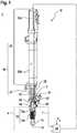
- Figure 1 shows a print head 10 in a perspective external view.
- the print head 10 has a housing 19 which has a funnel-shaped feed 12 for a starting material 21 in the form of granules 21.
- the housing 19 merges into an intermediate piece 38 at the top.
- This intermediate piece 38 comprises a cylinder 37 in which a piston 31 is guided.
- the piston 31 is in the in Figure 1 selected perspective covered by the cylinder 37 and therefore only indicated.
- the movement of the piston 31 is driven by an electric motor 32a, the rotary movement of which is translated into a linear movement by a mechanical spindle 32b.
- the piston 31 and the drive source 32 together form a conveying device 30 for conveying the granulate 21.
- the path s of the piston 31 is measured with a path measuring system 33.
- the force F with which the piston 31 presses on the granulate 21 is measured with a force sensor 34.
- the force F and the path s are fed to an active control 35, which also receives a setpoint Fs for the force F as input and controls the electric motor 32a to the effect that the actual force F is kept in accordance with the setpoint Fs.
- the measurement of the path s ensures compliance with the boundary condition that the piston 31 should only come into contact with the completely solid granulate 21 of the starting material 20, but not with an at least partially plasticized phase that sticks the piston 31.
- the housing 19 is formed by coolant 13, which includes active cooling 13a with a cooling medium and passive cooling 13b with cooling fins.
- the housing 16 is surrounded on its outer circumference by a heating band 15 which provides the heating energy for the plasticization of the starting material 21.
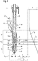
- FIG. 10 shows the interior of the printhead 10 at the portion of the duty cycle that is printing.
- the piston 31 conveys the granulate 21 from the feed zone 11 into the plasticizing zone 14, also known as the metering zone called because this is where the starting material 21 is measured in portions.
- the feed zone 11 adjoins the plasticization zone 14 via a compression zone 11a.
- Within the compression zone 11a there is the boundary layer 11b between highly compressed, but still firm and non-sticky granulate 21 on the one hand and material 22 that has started to liquefy on the other.
- the position shown is the front end of the piston 31 exactly in this boundary layer 11b.
- the interior of the housing 19 is designed as a straight circular cylinder in the upper region of the housing 19 up to and including the boundary layer 11b, in which the piston 31 can be guided. Further down, the interior merges into a melted geometry 51.
- This melting geometry 51 is distinguished, on the one hand, by the fact that its inner cross section tapers further and further downwards, so that the pressure of the liquid material 22 or the liquid phase 22 increases further and further.
- the inner wall of the melted geometry 51 has a structuring which effects a thorough mixing of the liquid phase 22 of the starting material 21. This structuring can be rib-shaped, for example, as shown in FIG Figure 2 is shown as an example.
- the heating band 15 is arranged on the outer circumference of the housing 19, the heating power of which is homogeneously distributed over the liquid phase 22 by a heat conducting structure 52 (heat conducting torpedo) arranged in the interior of the housing 19, i.e. within the liquid phase 22.
- a heat conducting structure 52 heat conducting torpedo
- Any other type of heating is also possible, as shown by the heating band 15 shown by way of example.
- the pressure p L of the liquid phase 22 is measured with a pressure sensor 17, and the temperature T L of the liquid phase 22 is measured with a temperature sensor 18.
- the area 16a is only a few cubic millimeters in size, so that no excess granulate 21 is melted.
- the heat conducting structure 52 ensures that the liquid phase 22 of the starting material 21 in the region 26a always has the highest possible viscosity without overheating.
- the measured values for p L and T L are forwarded to an evaluation unit 4, which also provides the temperature measured value T * a directly at the upper limit the plasticizing zone 14 arranged further temperature sensor 53 receives as input.
- a strand 23 is driven from the liquid phase 22 of the starting material 21 by the pressure p L generated by the piston 31 through the outlet opening 16 of the print head 10 and is deposited on an object 60 to be manufactured.
- the evaluation unit 4 calculates the amount ⁇ V + by which the volume of the strand 23 increases on the one hand due to the relaxation from the high pressure p L and by which amount ⁇ V - this volume decreases on the other hand due to the cooling from the high temperature T L.
- the energy input E into the object 60 by the deposited material 23 is also calculated.
- the piston 31 is guided in the housing 19 with a slight ventilation gap 54.
- the ambient air contained in the bed of granules 21, which is released when this bed is compressed, can be discharged through this gap 54.
- gases that arise during the plasticization or partial decomposition of the starting material 21 can also be discharged.
- the housing 19 is cooled between the boundary layer 11b and the feed 12 by coolant 13, which are formed from the active cooling 13a with a flowing cooling medium and from the passive cooling 13b by means of cooling fins.
- coolant 13 which are formed from the active cooling 13a with a flowing cooling medium and from the passive cooling 13b by means of cooling fins.
- the temperature profile along the longitudinal axis 10a of the print head 10 from cold (-) to warm (+) is drawn qualitatively to the right of the print head 10.
- FIG. 10 shows the same printhead 10 in the same view as in FIG Figure 2 with the difference that here the piston 31 has been withdrawn upwards behind the intake zone 11. On the one hand, this has the effect that the in Figure 3 In the state shown, no strand 23 of starting material 21 emerges from the outlet opening 16. On the other hand, the intake zone 11 is free for fresh granulate 21 to trickle down. When the piston 31 is lowered again, the fresh granulate 21, as in FIG Figure 2 shown, compressed and plasticized in the plasticizing zone 14 before it emerges as a strand 23 from the outlet opening 16.
- Figure 4 shows a first embodiment of the print head 10 according to the invention in a sectional drawing.
- the piston 31 has a first piston section 5, facing the plasticizing zone 14, with a guide surface 9 through which the piston 31 is guided in a bore 7 of the print head 10 or of the housing 19.
- the guide surface 9 is longer in its axial extent l 2 than a maximum axial extent l 1 of an opening surface 8 of the feed 12 to the bore 7.
- the opening surface 8 of the feed 12 to the bore 7 is designed so that the granules 21 fed optimally into the bore , or can be fed into the feed zone 11.
- the axial extension l 2 of the guide surface 9 of the piston 31 is 1.2 times the maximum axial extension l 1 of the opening surface 8 in this embodiment.
- the first piston section 5 has a piston diameter d 2 , the axial extent l 2 of the guide surface 9 of the piston 31 preferably being 1.25 times the piston diameter d 2 of the first piston section 5.
- the piston 31 shown with the correspondingly dimensioned guide surface 9 prevents the piston 31 from tilting in the bore 7 and reduces the penetration of the deformed granulate into the gap between the guide surface 9 and the bore 7.
- the piston 31 also has a second piston section 6, the piston diameter d 1 of which is smaller than the piston diameter d 2 of the first piston section 5.
- Figure 5 shows a second exemplary embodiment of the print head 10, the piston 31 having a recess 40 which is arranged between the first piston section and a third piston section 41.
- the third piston section 41 is arranged between the first 5 and the second 6 piston sections and it has the same piston diameter d 2 as the first piston section (5).
- the groove 40 is used to evaluate the quality of the print head settings by checking the groove 40 for deposits during the maintenance intervals.
- the axial extension l 2 of the guide surface 9 of the piston 31 is 1.2 times the maximum axial extension l 1 of the opening surface 8 and extends to the recess 40.
- the print head 10 can be integrated into any desired 3D printer.
Landscapes
- Engineering & Computer Science (AREA)
- Materials Engineering (AREA)
- Chemical & Material Sciences (AREA)
- Mechanical Engineering (AREA)
- Manufacturing & Machinery (AREA)
- Optics & Photonics (AREA)
- Physics & Mathematics (AREA)
- Health & Medical Sciences (AREA)
- Environmental & Geological Engineering (AREA)
- Toxicology (AREA)
- Clinical Laboratory Science (AREA)
- Processing And Handling Of Plastics And Other Materials For Molding In General (AREA)
- Ink Jet (AREA)
Description
- Die vorliegende Erfindung betrifft einen Druckkopf für einen 3D-Drucker.
- Ein 3D-Drucker für ein in seiner Viskosität veränderliches Material erhält eine feste Phase dieses Materials als Ausgangsmaterial, erzeugt daraus eine flüssige Phase und bringt diese flüssige Phase selektiv an den Stellen, die zu dem zu erzeugenden Objekt gehören, auf. Ein solcher 3D-Drucker umfasst einen Druckkopf, in dem das Ausgangsmaterial druckfertig aufbereitet wird. Weiterhin sind Mittel zur Erzeugung einer Relativbewegung zwischen dem Druckkopf und der Arbeitsfläche, auf der das Objekt entstehen soll, vorgesehen. Dabei können entweder nur der Druckkopf, nur die Arbeitsfläche oder aber sowohl der Druckkopf als auch die Arbeitsfläche bewegt werden.
- Der Druckkopf hat einen ersten Betriebszustand, in dem flüssiges Material aus ihm austritt, und einen zweiten Betriebszustand, in dem kein flüssiges Material aus ihm austritt. Der zweite Betriebszustand wird beispielsweise dann eingenommen, wenn eine andere Position auf der Arbeitsfläche angefahren werden und auf dem Weg dorthin kein Material deponiert werden soll. Zwischen den beiden Betriebszuständen des Druckkopfes kann beispielsweise umgeschaltet werden, indem der Vortrieb des festen Ausgangsmaterials ein- bzw. ausgeschaltet wird.
- Am verbreitetsten ist das "fused deposition modeling" (FDM), bei dem ein Filament aus dem Ausgangsmaterial in einer elektrisch beheizten Extruderdüse aufgeschmolzen und schichtweise auf eine Plattform aufgebracht wird. In Form eines derartigen Filaments ist das Ausgangsmaterial sehr teuer. In der
US 2016/082 627 A1 wird vorgeschlagen, das Ausgangsmaterial in Granulatform zuzuführen und mit einer Förderschnecke zu einer beheizten Zone zu fördern, aus der es in plastifizierter Form austritt. Zum einen ist Granulat deutlich günstiger, und zum anderen können Mischungen aus verschiedenen thermoplastischen Materialien auf diese Weise einfach hergestellt werden. - Ferner ist aus der zum Zeitpunkt dieser Anmeldung noch nicht veröffentlichten Anmeldung
DE102016222306 bekannt, ein Granulat über einen Kolben und eine beheizte Strecke zu plastifizieren. Wenn der Kolben auf das Granulat drückt, wird dieses verdichtet und zu einer Plastifizierungszone gefördert. Dabei treten Kräfte auf, die den Kolben und eine Zylinderwandung des Druckkopfes stark beanspruchen. - Die Schrift
WO 90/02034 A1 - In der
US 5 649 277 A ist eine Vorrichtung zur Erzeugung dreidimensionaler Objekte gezeigt, wobei erhitztes Material über eine Düse schichtweise aufgetragen wird. - Der Erfindung liegt die Aufgabe zugrunde, einen Druckkopf bereitzustellen, der den auftretenden Kräften Stand hält und einen stabilen Druckprozess ermöglicht.
- Im Rahmen der Erfindung wurde ein Druckkopf für einen 3D-Drucker entwickelt. Dieser Druckkopf umfasst eine Einzugszone mit einer Zuführung für ein in seiner Viskosität veränderliches Ausgangsmaterial, eine Plastifizierungszone mit einer Heizung und einer Austrittsöffnung für die flüssige Phase des Ausgangsmaterials sowie eine Fördervorrichtung zur Förderung des Granulats von der Einzugszone in die Plastifizierungszone, wobei die Fördervorrichtung einen in die Einzugszone einführbaren Kolben umfasst.
- Dabei kann insbesondere eine Zuführung für ein als Granulat vorliegendes Ausgangsmaterial vorgesehen sein. Das Ausgangsmaterial kann insbesondere ein thermoplastisches Material sein.
- Im Vergleich zu einem Druckkopf, der Granulat mit einer Förderschnecke transportiert, lässt sich der Druckkopf gemäß der Erfindung kompakter bauen. Dies wiederum hat zur Folge, dass der Druckkopf leichter und einfacher bewegbar ist. Dies ist insbesondere dann von Vorteil, wenn der Druckkopf sehr schnell, insbesondere mit Geschwindigkeiten von 100 mm/s oder mehr, bewegt werden soll.
- Weiterhin wurde überraschenderweise erkannt, dass die Förderung des Ausgangsmaterials mit dem Kolben die Qualität des Materials besser erhält als die Förderung mit einer Förderschnecke.
- Zum einen kann die Zeitdauer, für die das Material oberhalb seiner Schmelztemperatur verweilt, deutlich reduziert werden, so dass es in geringerem Maße thermisch degeneriert. Durch eine zu hohe thermische Belastung entstehen Spaltprodukte, in erster Linie Gase, welche durch die im System vorherrschenden Drücke eine weitere Zersetzung des Materials beschleunigen und auch direkt dessen Qualität beeinflussen. Dies äußert sich beispielsweise in Schwankungen des extrudierten Volumens oder auch durch eine Verfärbung, oberflächliche Verbrennung oder ein Schäumen des extrudierten Materials. Des Weiteren bilden sich Beläge im System, welche sich lösen und das System verstopfen oder als lose Partikel in das herzustellende Objekt gelangen. Durch den Druck gasförmiger Spaltprodukte kann weiterhin auch ungewollt Material extrudiert werden. Ist die Austrittsöffnung durch ein Ventil verschlossen, kann sich hier sogar ein Überdruck aufbauen und der Druckkopf explodieren. Ist die Austrittsöffnung durch feste Spaltprodukte verschlossen, kann sich ebenfalls ein Druck im Druckkopf aufbauen, der sich in einer explosionsartigen Extrusion heißen Materials entladen kann. Auf Grund der Nachwärme kann dies auch dann noch passieren, wenn durch ein Sicherheitssystem die Energiezufuhr zur Heizung des Druckkopfes bereits abgeschaltet wurde.
- Zum anderen werden auch keine Scherkräfte auf das Material ausgeübt, die Polymerketten des Materials zerteilen. Je länger diese Polymerketten sind, desto größer ist die mechanische Festigkeit des letztendlich erhaltenen Objekts gegenüber beispielsweise Zug- Druck- und Biegebeanspruchungen. Auch die Beständigkeit des Objekts gegen chemische Medien ist umso besser, je länger die Polymerketten sind.
- Weiterhin können beliebig kleine Volumina plastifiziert werden, wohingegen bei der Förderung mit einer Förderschnecke immer eine gewisse Mindestmenge an Material plastifiziert werden muss. Eine Förderschnecke benötigt eine derartige Mindestmenge, um die Schubkräfte aufzubauen, die für die Funktion der Förderschnecke zwingend erforderlich sind.
- Der Kolben weist einen der Plastifizierungszone zugewandten ersten Kolbenabschnitt mit einer Führungsfläche auf, durch die der Kolben in einer Bohrung des Druckkopfs geführt ist.
- Eine derartige Anordnung der Führungsfläche des Kolbens verhindert in vorteilhafter Weise ein Verklemmen und Verkanten des Kolbens in der Bohrung des Druckkopfs, wodurch ein quasi verschleißfreier Betrieb des Druckkopfes ermöglicht wird. Die Erfindung stellt sicher, dass der Kolben immer optimal in der Bohrung des Druckkopfs geführt wird und dieser beim Auftreffen auf das Granulat nicht ausweicht. Dadurch wird ein kontinuierlicher und dauerhafter Betrieb des Druckkopfs ermöglicht.
- Ferner ist die Führungsfläche in ihrer axialen Ausdehnung länger als eine maximale axiale Ausdehnung einer Öffnungsfläche der Zuführung zur Bohrung.
- Die Größe der Öffnungsfläche der Zuführung zur Bohrung ist relevant für die Menge des zugeführten Granulats aus der Zuführung in die Bohrung des Druckkopfs, bzw. in die Einzugszone des Druckkopfs.
- Der durch die Erfindung ermöglichte Überstand der Führungsfläche des Kolbens zur Öffnungsfläche der Zuführung sorgt in vorteilhafter Weise für eine stabile Führung des Kolbens in der Bohrung.
- Besonders vorteilhafte Weiterbildungen der Erfindung ergeben sich bei einer axialen Ausdehnung der Führungsfläche des Kolbens zwischen dem 1,1- und dem 1,3-fachen der maximalen axialen Ausdehnung der Öffnungsfläche. Wird die Führungsfläche länger gewählt, verringert sich die Standzeit des Kolbens, da dieser zu starr geführt wird und sich dadurch Toleranzen nicht mehr ausgleichen lassen.
- Speziell, wenn die axiale Ausdehnung der Führungsfläche des Kolbens das 1,2-fache der maximalen axialen Ausdehnung der Öffnungsfläche beträgt, wird in vorteilhafter Weise erreicht, dass der Kolben optimal geführt wird und sich die Standzeit des Druckkopfes erhöht.
- Erfindungsgemäß beträgt die axiale Ausdehnung der Führungsfläche des Kolbens zwischen dem 1- und dem 2,5-fachen eines Kolbendurchmessers des ersten Kolbenabschnitts.
- Dieser Bereich ermöglicht in vorteilhafter Weise eine optimale Führung des Kolbens in der Bohrung, wodurch die Standzeit des Druckkopfs erhöht wird.
- Bei einem kleineren Wert steigt die Wahrscheinlichkeit eines Versagens des Druckkopfs und bei größeren Werten sind sehr genau gefertigte und aufeinander abgestimmte Bauteile notwendig, die zum einen teuer sind und gegebenenfalls eine geringere Festigkeit aufweisen und dadurch störanfälliger sind.
- Speziell, wenn die axiale Ausdehnung der Führungsfläche des Kolbens das 1,25-fache des Kolbendurchmessers des ersten Kolbenabschnitts beträgt, wird in vorteilhafter Weise erreicht, dass der Kolben optimal geführt wird und sich die Standzeit des Druckkopfs erhöht.
- In einer Weiterbildung weist der Kolben einen zweiten Kolbenabschnitt auf, dessen Kolbendurchmesser kleiner ist als der Kolbendurchmesser des ersten Kolbenabschnitts, wodurch der Kolben in diesem Abschnitt in vorteilhafter Weise nicht geführt wird.
- In einer weiteren Ausführung der Erfindung weist der Kolben einen Einstich auf, der zwischen dem ersten Kolbenabschnitt und einem dritten Kolbenabschnitt angeordnet ist, wobei der dritte Kolbenabschnitt in einer Weiterbildung zwischen dem ersten und dem zweiten Kolbenabschnitt angeordnet ist, wobei der erste Kolbenabschnitt und der dritte Kolbenabschnitt den gleichen Kolbendurchmesser aufweisen.
- Durch die Anordnung des Einstichs zwischen dem ersten und dritten Kolbenabschnitt, die jeweils den gleichen Kolbendurchmesser aufweisen, kann in vorteilhafter Weise der Zustand des Druckkopfs, bzw. des Extruders bewertet werden, indem der Einstich während eines Wartungsintervalls auf Verunreinigungen überprüft wird. Ist der Einstich frei von Verunreinigungen, oder eines Belags des Ausgangsmaterials, sind beispielsweise die Temperatur zum Erhitzen des Ausgangsmaterials und die Führung des Kolbens korrekt eingestellt.
- Weitere, die Erfindung verbessernde Maßnahmen werden nachstehend gemeinsam mit der Beschreibung der bevorzugten Ausführungsbeispiele der Erfindung anhand von Figuren näher dargestellt.
- Es zeigen:
- Fig. 1
- einen Druckkopf gemäß der Erfindung;
- Fig. 2
- eine Schnittzeichnung des Druckkopfes im druckenden Zustand;
- Fig. 3
- eine Schnittzeichnung des Druckkopfes im nicht druckenden Zustand;
- Fig. 4
- ein erstes Ausführungsbeispiel für einen Druckkopf und
- Fig. 5
- ein zweites Ausführungsbeispiel für einen Druckkopf.
-
Figur 1 zeigt einen Druckkopf 10 in perspektivischer Außenansicht. Der Druckkopf 10 weist ein Gehäuse 19 auf, welches eine trichterförmige Zuführung 12 für ein Ausgangsmaterial 21 in Form von Granulat 21 aufweist. Das Gehäuse 19 geht nach oben hin in ein Zwischenstück 38 über. Dieses Zwischenstück 38 umfasst einen Zylinder 37, in der ein Kolben 31 geführt ist. Der Kolben 31 ist in der inFigur 1 gewählten Perspektive durch den Zylinder 37 verdeckt und daher nur angedeutet. Die Bewegung des Kolbens 31 wird über einen Elektromotor 32a, dessen Drehbewegung durch eine mechanische Spindel 32b in eine Linearbewegung übersetzt ist, angetrieben. Kolben 31 und Antriebsquelle 32 bilden gemeinsam eine Fördervorrichtung 30 zur Förderung des Granulats 21. - Der Weg s des Kolbens 31 wird mit einem Wegmesssystem 33 gemessen. Die Kraft F, mit der der Kolben 31 auf das Granulat 21 drückt, wird mit einem Kraftsensor 34 gemessen. Die Kraft F und der Weg s werden einer aktiven Regelung 35 zugeführt, die weiterhin einen Sollwert Fs für die Kraft F als Eingabe erhält und den Elektromotor 32a dahingehend ansteuert, dass die tatsächliche Kraft F in Übereinstimmung mit dem Sollwert Fs gehalten wird. Dabei wird durch die Messung des Weges s die Einhaltung der Randbedingung sichergestellt, dass der Kolben 31 nur mit dem vollständig festen Granulat 21 des Ausgangsmaterials 20 in Berührung kommen soll, nicht jedoch mit einer zumindest teilweise plastifizierten Phase, die den Kolben 31 verklebt.
- Im oberen Bereich, der der Zuführung 12 zugewandt ist, ist das Gehäuse 19 durch Kühlmittel 13 gebildet, die eine aktive Kühlung 13a mit einem Kühlmedium und eine passive Kühlung 13b mit Kühlrippen umfassen. Im unteren Bereich, der der Austrittsöffnung 16 zugewandt ist, ist das Gehäuse 16 hingegen an seinem Außenumfang von einem Heizband 15 umgeben, das die Heizenergie für die Plastifizierung des Ausgangsmaterials 21 bereitstellt.
-
Figur 2 zeigt das Innere des Druckkopfes 10 in dem Teil des Arbeitszyklus, in dem gedruckt wird. Im Gehäuse 19 des Druckkopfes 10 befindet sich eine Einzugszone 11, in die über die trichterförmige Zuführung 12 das Granulat 21, bzw. das Ausgangsmaterial 21 zuführbar ist. Der Kolben 31 fördert das Granulat 21 aus der Einzugszone 11 in die Plastifizierungszone 14, auch Meteringzone genannt, weil dort das portionsweise Abmessen des Ausgangsmaterials 21 stattfindet. Die Einzugszone 11 grenzt über eine Kompressionszone 11a an die Plastifizierungszone 14. Innerhalb der Kompressionszone 11a befindet sich die Grenzschicht 11b zwischen stark komprimiertem, aber immer noch festem und nicht klebrigem Granulat 21 einerseits und Material 22, dessen Verflüssigung begonnen hat, andererseits. In der inFigur 2 gezeigten Stellung befindet sich das vordere Ende des Kolbens 31 genau in dieser Grenzschicht 11b. - Der Innenraum des Gehäuses 19 ist im oberen Bereich des Gehäuses 19 bis einschließlich zur Grenzschicht 11b als gerader Kreiszylinder ausgebildet, in dem der Kolben 31 führbar ist. Weiter unten geht der Innenraum in eine Aufschmelzgeometrie 51 über. Diese Aufschmelzgeometrie 51 zeichnet sich zum einen dadurch aus, dass sich ihr Innenquerschnitt nach unten hin immer weiter verjüngt, so dass sich der Druck des flüssigen Materials 22, bzw. der flüssigen Phase 22 immer weiter erhöht. Zum anderen weist die Innenwand der Aufschmelzgeometrie 51 eine Strukturierung auf, die eine Durchmischung der flüssigen Phase 22 des Ausgangsmaterials 21 bewirkt. Diese Strukturierung kann beispielsweise rippenförmig sein, wie es in
Figur 2 beispielhaft eingezeichnet ist. In der Plastifizierungszone 14 ist am Außenumfang des Gehäuses 19 das Heizband 15 angeordnet, dessen Heizleistung durch eine im Innenraum des Gehäuses 19, also innerhalb der flüssigen Phase 22, angeordnete Wärmeleitstruktur 52 (Wärmeleittorpedo) homogen über die flüssige Phase 22 verteilt wird. An Stelle des in denFiguren 1 und2 beispielhaft eingezeichneten Heizbandes 15 ist auch jede andere Art der Heizung möglich. Im der Austrittsöffnung 16 am nächsten gelegenen vorderen Bereich 16a der Plastifizierungszone 14 wird der Druck pL der flüssigen Phase 22 mit einem Drucksensor 17 gemessen, und die Temperatur TL der flüssigen Phase 22 wird mit einem Temperatursensor 18 gemessen. Der Bereich 16a ist nur wenige Kubikmillimeter groß, so dass kein überschüssiges Granulat 21 aufgeschmolzen wird. Die Wärmeleitstruktur 52 sorgt dafür, dass die flüssige Phase 22 des Ausgangsmaterials 21 in dem Bereich 26a stets die höchstmögliche Viskosität aufweist, ohne sich zu überhitzen. - Die Messwerte für pL und TL werden an eine Auswerteeinheit 4 weitergeleitet, die zusätzlich den Temperaturmesswert T* eines unmittelbar an der oberen Grenze der Plastifizierungszone 14 angeordneten weiteren Temperatursensors 53 als Eingabe erhält.
- Aus der flüssigen Phase 22 des Ausgangsmaterials 21 wird durch den vom Kolben 31 erzeugten Druck pL ein Strang 23 durch die Austrittsöffnung 16 des Druckkopfes 10 getrieben und lagert sich auf einem zu fertigenden Objekt 60 ab. Die Auswerteeinheit 4 berechnet, um welchen Betrag ΔV+ das Volumen des Strangs 23 einerseits durch die Entspannung vom hohen Druck pL zunimmt und um welchen Betrag ΔV- dieses Volumen andererseits durch die Abkühlung von der hohen Temperatur TL abnimmt. Zugleich wird auch der Energieeintrag E in das Objekt 60 durch das angelagerte Material 23 berechnet.
- Der Kolben 31 ist im Gehäuse 19 mit einem geringfügigen Entlüftungsspalt 54 geführt. Durch diesen Spalt 54 kann die in der Schüttung des Granulats 21 enthaltene Umgebungsluft, die bei der Kompression dieser Schüttung frei wird, abgeführt werden. Auf dem gleichen Weg können auch Gase, die bei der Plastifizierung bzw. teilweisen Zersetzung des Ausgangsmaterials 21 entstehen, abgeführt werden.
- Wie bereits in
Figur 1 angedeutet, ist das Gehäuse 19 zwischen der Grenzschicht 11b und der Zuführung 12 durch Kühlmittel 13 gekühlt, die aus der aktiven Kühlung 13a mit einem strömenden Kühlmedium sowie aus der passiven Kühlung 13b mittels Kühlrippen gebildet werden. Dadurch wird die Temperatur Ts innerhalb der Einzugszone 11, die von oben nach unten stetig ansteigt, ständig unterhalb der Temperatur TP gehalten, ab der das Ausgangsmaterial 21 plastifiziert. TP wird gerade am unteren Ende der Grenzschicht 11b erreicht. Indem die Einzugszone 11 permanent auf eine geeignete Temperatur temperiert wird, werden ein zu frühes Aufschmelzen des Granulats 21, ein Verstopfen der Einzugszone 11 und ein Wassereintrag durch Kondensation vermieden. Auch regelt diese Temperierung die genaue Lage der Grenzschicht 11b und kann sie insbesondere in einer konstanten Position halten. - Der Temperaturverlauf entlang der Längsachse 10a des Druckkopfes 10 von kalt (―) zu warm (+) ist rechts neben dem Druckkopf 10 qualitativ eingezeichnet.
-
Figur 3 zeigt den gleichen Druckkopf 10 in der gleichen Ansicht wie inFigur 2 mit dem Unterschied, dass hier der Kolben 31 nach oben hinter die Einzugszone 11 zurückgezogen wurde. Dies hat zum einen den Effekt, dass in dem inFigur 3 gezeigten Zustand kein Strang 23 von Ausgangsmaterial 21 aus der Austrittsöffnung 16 austritt. Zum anderen ist die Einzugszone 11 frei für das Nachrieseln von frischem Granulat 21. Wenn der Kolben 31 wieder gesenkt wird, wird das frische Granulat 21, wie inFigur 2 gezeigt, komprimiert und in der Plastifizierungszone 14 plastifiziert, bevor es als Strang 23 aus der Austrittsöffnung 16 austritt. -
Figur 4 zeigt ein erstes Ausführungsbeispiel des erfindungsgemäßen Druckkopfes 10 in einer Schnittzeichnung. Der Kolben 31 weist einen, der Plastifizierungszone 14 zugewandten, ersten Kolbenabschnitt 5 mit einer Führungsfläche 9 auf, durch die der Kolben 31 in einer Bohrung 7 des Druckkopfs 10, bzw. des Gehäuses 19 geführt ist. - Die Führungsfläche 9 ist in ihrer axialen Ausdehnung l2 länger als eine maximale axiale Ausdehnung l1 einer Öffnungsfläche 8 der Zuführung 12 zur Bohrung 7. Die Öffnungsfläche 8 der Zuführung 12 zur Bohrung 7 ist derart ausgelegt, dass das zugeführte Granulat 21 optimal in die Bohrung, bzw. in die Einzugszone 11 zugeführt werden kann.
- Die axiale Ausdehnung l2 der Führungsfläche 9 des Kolbens 31 beträgt in dieser Ausführungsform das 1,2-fache der maximalen axialen Ausdehnung l1 der Öffnungsfläche 8.
- Ferner weist der erste Kolbenabschnitt 5 einen Kolbendurchmesser d2 auf, wobei die axiale Ausdehnung l2 der Führungsfläche 9 des Kolbens 31 bevorzugt das 1,25-fache des Kolbendurchmessers d2 des ersten Kolbenabschnitts 5 beträgt.
- Der dargestellte Kolben 31 mit der entsprechend dimensionierten Führungsfläche 9 vermeidet ein Verkanten des Kolbens 31 in der Bohrung 7 und verringert ein Eindringen des verformten Granulats in den Spalt zwischen der Führungsfläche 9 und der Bohrung 7.
- Der Kolben 31 weist ferner einen zweiten Kolbenabschnitt 6 auf, dessen Kolbendurchmesser d1 kleiner ist als der Kolbendurchmesser d2 des ersten Kolbenabschnitts 5.
-
Figur 5 zeigt ein zweites Ausführungsbeispiel des Druckkopfes 10, wobei der Kolben 31 einen Einstich 40 aufweist, der zwischen dem ersten Kolbenabschnitt und einem dritten Kolbenabschnitt 41 angeordnet ist. - Der dritte Kolbenabschnitt 41 ist zwischen dem ersten 5 und dem zweiten 6 Kolbenabschnitt angeordnet und er weist den gleichen Kolbendurchmesser d2 wie der erste Kolbenabschnitt (5) auf.
- Der Einstich 40 dient dazu die Qualität der Druckkopfeinstellungen zu bewerten, indem der Einstich 40 während der Wartungsintervalle auf Ablagerungen geprüft wird.
- Die axiale Ausdehnung l2 der Führungsfläche 9 des Kolbens 31 beträgt in dieser Ausführungsform das 1,2-fache der maximalen axialen Ausdehnung l1 der Öffnungsfläche 8 und reicht bis zum Einstich 40.
- Der Druckkopf 10 kann in beliebige 3D-Drucker integriert werden.
Claims (8)
- Druckkopf (10) für einen 3D-Drucker (1), umfassend eine Einzugszone (11) mit einer Zuführung (12) für ein in seiner Viskosität veränderliches Ausgangsmaterial (21), eine Plastifizierungszone (14) mit einer Heizung (15) und einer Austrittsöffnung (16) für die flüssige Phase (22) des Ausgangsmaterials (21) sowie eine Fördervorrichtung (30) zur Förderung des Ausgangsmaterials (21) von der Einzugszone (11) in die Plastifizierungszone (14), wobei die Fördervorrichtung (30) einen in die Einzugszone (11) einführbaren Kolben (31) umfasst, wobeider Kolben (31) einen der Plastifizierungszone (14) zugewandten ersten Kolbenabschnitt (5) mit einer Führungsfläche (9) aufweist, durch die der Kolben (31) in einer Bohrung (7) des Druckkopfs (10) geführt ist, dadurch gekennzeichnet, dassdie Führungsfläche (9) in ihrer axialen Ausdehnung (l2) länger ist, als eine maximale axiale Ausdehnung (l1) einer Öffnungsfläche (8) der Zuführung (12) zur Bohrung (7), und,die axiale Ausdehnung (l2) der Führungsfläche (9) des Kolbens (31) zwischen dem 1- und dem 2,5-fachen eines Kolbendurchmessers (d2) des ersten Kolbenabschnitts (5) beträgt.
- Druckkopf (10) nach Anspruch 1
dadurch gekennzeichnet, dass
die axiale Ausdehnung (l2) der Führungsfläche (9) des Kolbens (31) zwischen dem 1,1- und dem 1,3-fachen der maximalen axialen Ausdehnung (l1) der Öffnungsfläche (8) beträgt. - Druckkopf (10) nach einem der vorhergehenden Ansprüche, dadurch gekennzeichnet, dass
die axiale Ausdehnung (l2) der Führungsfläche (9) des Kolbens (31) das 1,2-fache der maximalen axialen Ausdehnung (l1) der Öffnungsfläche (8) beträgt. - Druckkopf (10) nach einem der vorhergehenden Ansprüche, dadurch gekennzeichnet, dass
die axiale Ausdehnung (l2) der Führungsfläche (9) des Kolbens (31) das 1,25-fache des Kolbendurchmessers (d2) des ersten Kolbenabschnitts (5) beträgt. - Druckkopf (10) nach einem der vorhergehenden Ansprüche, dadurch gekennzeichnet, dass
der Kolben (31) einen zweiten Kolbenabschnitt (6) aufweist, dessen Kolbendurchmesser (d1) kleiner ist als der Kolbendurchmesser (d2) des ersten Kolbenabschnitts (5). - Druckkopf (10) nach einem der vorhergehenden Ansprüche, dadurch gekennzeichnet, dass
der Kolben (31) einen Einstich (40) aufweist, der zwischen dem ersten Kolbenabschnitt (5) und einem dritten Kolbenabschnitt (41) angeordnet ist. - Druckkopf (10) nach Anspruch 6,
dadurch gekennzeichnet, dass
der dritte Kolbenabschnitt (41) zwischen dem ersten (5) und dem zweiten (6) Kolbenabschnitt angeordnet ist. - Druckkopf (10) nach Anspruch 7,
dadurch gekennzeichnet, dass
der erste Kolbenabschnitt (5) und der dritte Kolbenabschnitt (41) den gleichen Kolbendurchmesser (d2) aufweisen.
Applications Claiming Priority (2)
| Application Number | Priority Date | Filing Date | Title |
|---|---|---|---|
| DE102017218707.7A DE102017218707A1 (de) | 2017-10-19 | 2017-10-19 | Druckkopf für einen 3D-Drucker |
| PCT/EP2018/078403 WO2019076982A1 (de) | 2017-10-19 | 2018-10-17 | Druckkopf für einen 3d-drucker |
Publications (2)
| Publication Number | Publication Date |
|---|---|
| EP3697594A1 EP3697594A1 (de) | 2020-08-26 |
| EP3697594B1 true EP3697594B1 (de) | 2021-12-08 |
Family
ID=63915035
Family Applications (1)
| Application Number | Title | Priority Date | Filing Date |
|---|---|---|---|
| EP18789387.0A Active EP3697594B1 (de) | 2017-10-19 | 2018-10-17 | Druckkopf für einen 3d-drucker |
Country Status (5)
| Country | Link |
|---|---|
| US (1) | US11584072B2 (de) |
| EP (1) | EP3697594B1 (de) |
| CN (1) | CN111225782B (de) |
| DE (1) | DE102017218707A1 (de) |
| WO (1) | WO2019076982A1 (de) |
Cited By (1)
| Publication number | Priority date | Publication date | Assignee | Title |
|---|---|---|---|---|
| WO2024132363A1 (de) * | 2022-12-19 | 2024-06-27 | Robert Bosch Gmbh | Druckkopf für einen 3d-drucker |
Families Citing this family (3)
| Publication number | Priority date | Publication date | Assignee | Title |
|---|---|---|---|---|
| DE102016222306A1 (de) * | 2016-11-14 | 2018-05-17 | Robert Bosch Gmbh | Besser kontrollierbarer Druckkopf für 3D-Drucker |
| GB2620611A (en) * | 2022-07-13 | 2024-01-17 | Kraft Foods Schweiz Holding Gmbh | A method and apparatus for forming a steady stream of plasticised solid feed material |
| DE102022213850A1 (de) | 2022-12-19 | 2024-06-20 | Robert Bosch Gesellschaft mit beschränkter Haftung | Druckkopf für einen 3D-Drucker |
Family Cites Families (19)
| Publication number | Priority date | Publication date | Assignee | Title |
|---|---|---|---|---|
| DE3827772A1 (de) | 1988-08-16 | 1990-02-22 | Thomas Paul Engel | Vorrichtung und verfahren zur formgebung von halbzeug aus hochmolekularen kunststoffen |
| DE4319128C1 (de) * | 1993-06-09 | 1995-02-23 | Fraunhofer Ges Forschung | Verfahren und Einrichtung zur freiformenden Herstellung dreidimensionaler Bauteile einer vorgegebenen Form |
| JPH10235701A (ja) * | 1997-02-27 | 1998-09-08 | Mitsubishi Heavy Ind Ltd | 射出成形機の射出装置 |
| US6067480A (en) | 1997-04-02 | 2000-05-23 | Stratasys, Inc. | Method and apparatus for in-situ formation of three-dimensional solid objects by extrusion of polymeric materials |
| US6200127B1 (en) * | 1999-02-26 | 2001-03-13 | Milacron Inc. | Bi-directional check ring for a two-stage injection unit |
| DE102006035816B4 (de) * | 2006-08-01 | 2009-12-17 | Landshuter Werkzeugbau Alfred Steinl Gmbh & Co. Kg | Drossel für Spritzgießmaschine zum Spritzgießen von Kautschuk- bzw. Elastomermaterialien |
| US8323247B2 (en) * | 2009-05-08 | 2012-12-04 | The Alfred E. Mann Foundation For Scientific Research | Fluid transfer devices with fluid bypass and ambulatory infusion devices including same |
| KR101353564B1 (ko) * | 2012-11-15 | 2014-01-22 | 한국생산기술연구원 | 혼합성능이 개선된 믹싱헤드 및 그 토출장치 |
| US9186846B1 (en) * | 2013-03-22 | 2015-11-17 | Markforged, Inc. | Methods for composite filament threading in three dimensional printing |
| US9579851B2 (en) * | 2013-03-22 | 2017-02-28 | Markforged, Inc. | Apparatus for fiber reinforced additive manufacturing |
| GB2516002A (en) | 2013-05-15 | 2015-01-14 | Rafael Zvi Karl Kilim | Plastic moulding method |
| WO2015115106A1 (ja) * | 2014-01-31 | 2015-08-06 | 古河ロックドリル株式会社 | 液圧式打撃装置 |
| JP2015168135A (ja) * | 2014-03-06 | 2015-09-28 | 三井化学株式会社 | 三次元物体の製造装置および三次元物体の製造方法 |
| US10279541B2 (en) * | 2015-06-26 | 2019-05-07 | The Boeing Company | Systems and methods for additive manufacturing processes |
| GB201519730D0 (en) | 2015-11-09 | 2015-12-23 | Univ Dublin | A method, system and device for three dimensional additive manufacturing in a liquid phase |
| DE102016222315A1 (de) | 2016-11-14 | 2018-05-17 | Robert Bosch Gmbh | 3D-Druckkopf mit verbesserter Reproduzierbarkeit des Druckergebnisses |
| DE102016222306A1 (de) | 2016-11-14 | 2018-05-17 | Robert Bosch Gmbh | Besser kontrollierbarer Druckkopf für 3D-Drucker |
| NL2018720B1 (en) * | 2017-04-14 | 2018-10-24 | Bond High Performance 3D Tech B V | Three-dimensional modeling method and system |
| WO2018200596A1 (en) * | 2017-04-24 | 2018-11-01 | Desktop Metal, Inc. | Moving build material using a gripper in a 3d printing system |
-
2017
- 2017-10-19 DE DE102017218707.7A patent/DE102017218707A1/de not_active Withdrawn
-
2018
- 2018-10-17 CN CN201880067777.6A patent/CN111225782B/zh active Active
- 2018-10-17 EP EP18789387.0A patent/EP3697594B1/de active Active
- 2018-10-17 US US16/757,442 patent/US11584072B2/en active Active
- 2018-10-17 WO PCT/EP2018/078403 patent/WO2019076982A1/de not_active Ceased
Cited By (1)
| Publication number | Priority date | Publication date | Assignee | Title |
|---|---|---|---|---|
| WO2024132363A1 (de) * | 2022-12-19 | 2024-06-27 | Robert Bosch Gmbh | Druckkopf für einen 3d-drucker |
Also Published As
| Publication number | Publication date |
|---|---|
| WO2019076982A1 (de) | 2019-04-25 |
| US20210187842A1 (en) | 2021-06-24 |
| CN111225782B (zh) | 2022-03-25 |
| CN111225782A (zh) | 2020-06-02 |
| US11584072B2 (en) | 2023-02-21 |
| EP3697594A1 (de) | 2020-08-26 |
| DE102017218707A1 (de) | 2019-04-25 |
Similar Documents
| Publication | Publication Date | Title |
|---|---|---|
| EP3538366A1 (de) | Besser kontrollierbarer druckkopf für 3d-drucker | |
| EP4308383B1 (de) | Verfahren zum bereitstellen druckfähiger schmelze zum betreiben eines druckkopfes für einen 3d-drucker | |
| DE69903084T2 (de) | Verfahren und System zur Verminderung der Polymerdegradation von Produkten in zweistufigen Spritzgiessmaschinen | |
| DE69523651T2 (de) | Spritzgiessvorrichtung vom Vorplastifiziertyp | |
| WO2018015092A1 (de) | Extruder für 3d-drucker mit variablem materialdurchsatz | |
| DE3835250C1 (de) | ||
| WO2019076982A1 (de) | Druckkopf für einen 3d-drucker | |
| DE102007051923A1 (de) | Vorrichtung und Verfahren zur Verarbeitung polymerer Werkstoffe | |
| DE1554756B2 (de) | Schneckenstrangpresse zur verarbeitung thermoplastischer werkstoffe | |
| EP0846050B1 (de) | Spritzgiessmaschine mit integriertem heisskanalsystem | |
| WO2019109114A1 (de) | Druckkopf für das schichtweise aufbringen von material | |
| EP1884341A2 (de) | Vorrichtung zur Herstellung von strangförmigen Gütern | |
| DE2059496C3 (de) | Vorrichtung zum Plastifizieren von Kunststoffen | |
| EP0107778A2 (de) | Verfahren und Vorrichtung zur Verarbeitung einer plastifizierbaren Masse | |
| DE102006001171A1 (de) | Extruder mit Materialeintrag durch Gehäuse und Entgasung | |
| EP3524402B1 (de) | Nadelverschlussdüse mit separatem nadelkanal und schmelzekanal | |
| DE19904227A1 (de) | Schneckenmaschine und Verfahren zum Recycling von Thermoplast-Schaum-Materialien | |
| DE3917678C2 (de) | ||
| EP3569384A1 (de) | Vorrichtung zum extrudieren von faserverstärkten kunststoffen | |
| EP3554797A1 (de) | Druckkopf für das schichtweise aufbringen von material | |
| DE19801412C2 (de) | Plastifizier- und Einspritzeinheit für eine Spritzgießmaschine | |
| EP0663277B1 (de) | Extrudierschweissgerät zum Verschweissen von thermoplastischen Kunststoffmaterialien | |
| WO2022195062A1 (de) | Druckkopf für einen 3d-drucker und verfahren zum betreiben eines druckkopfes | |
| EP4045248A1 (de) | Mischteil für eine plastifiziereinheit einer schneckenmaschine | |
| DE102024000241B4 (de) | Spritzgießcompounder und Verfahren zu dessen Herstellung sowie Einsatz und dessen Verwendung |
Legal Events
| Date | Code | Title | Description |
|---|---|---|---|
| STAA | Information on the status of an ep patent application or granted ep patent |
Free format text: STATUS: UNKNOWN |
|
| STAA | Information on the status of an ep patent application or granted ep patent |
Free format text: STATUS: THE INTERNATIONAL PUBLICATION HAS BEEN MADE |
|
| PUAI | Public reference made under article 153(3) epc to a published international application that has entered the european phase |
Free format text: ORIGINAL CODE: 0009012 |
|
| STAA | Information on the status of an ep patent application or granted ep patent |
Free format text: STATUS: REQUEST FOR EXAMINATION WAS MADE |
|
| 17P | Request for examination filed |
Effective date: 20200519 |
|
| AK | Designated contracting states |
Kind code of ref document: A1 Designated state(s): AL AT BE BG CH CY CZ DE DK EE ES FI FR GB GR HR HU IE IS IT LI LT LU LV MC MK MT NL NO PL PT RO RS SE SI SK SM TR |
|
| AX | Request for extension of the european patent |
Extension state: BA ME |
|
| DAV | Request for validation of the european patent (deleted) | ||
| DAX | Request for extension of the european patent (deleted) | ||
| GRAP | Despatch of communication of intention to grant a patent |
Free format text: ORIGINAL CODE: EPIDOSNIGR1 |
|
| STAA | Information on the status of an ep patent application or granted ep patent |
Free format text: STATUS: GRANT OF PATENT IS INTENDED |
|
| RIC1 | Information provided on ipc code assigned before grant |
Ipc: B29C 64/106 20170101AFI20210527BHEP Ipc: B29C 64/209 20170101ALI20210527BHEP Ipc: B33Y 30/00 20150101ALI20210527BHEP Ipc: B29C 48/02 20190101ALI20210527BHEP Ipc: B29C 48/25 20190101ALI20210527BHEP Ipc: B29C 48/92 20190101ALI20210527BHEP Ipc: B29C 48/05 20190101ALN20210527BHEP |
|
| INTG | Intention to grant announced |
Effective date: 20210611 |
|
| GRAS | Grant fee paid |
Free format text: ORIGINAL CODE: EPIDOSNIGR3 |
|
| GRAA | (expected) grant |
Free format text: ORIGINAL CODE: 0009210 |
|
| STAA | Information on the status of an ep patent application or granted ep patent |
Free format text: STATUS: THE PATENT HAS BEEN GRANTED |
|
| AK | Designated contracting states |
Kind code of ref document: B1 Designated state(s): AL AT BE BG CH CY CZ DE DK EE ES FI FR GB GR HR HU IE IS IT LI LT LU LV MC MK MT NL NO PL PT RO RS SE SI SK SM TR |
|
| REG | Reference to a national code |
Ref country code: GB Ref legal event code: FG4D Free format text: NOT ENGLISH |
|
| REG | Reference to a national code |
Ref country code: AT Ref legal event code: REF Ref document number: 1453430 Country of ref document: AT Kind code of ref document: T Effective date: 20211215 Ref country code: CH Ref legal event code: EP |
|
| REG | Reference to a national code |
Ref country code: DE Ref legal event code: R096 Ref document number: 502018008166 Country of ref document: DE |
|
| REG | Reference to a national code |
Ref country code: IE Ref legal event code: FG4D Free format text: LANGUAGE OF EP DOCUMENT: GERMAN |
|
| REG | Reference to a national code |
Ref country code: LT Ref legal event code: MG9D |
|
| REG | Reference to a national code |
Ref country code: NL Ref legal event code: MP Effective date: 20211208 |
|
| PG25 | Lapsed in a contracting state [announced via postgrant information from national office to epo] |
Ref country code: RS Free format text: LAPSE BECAUSE OF FAILURE TO SUBMIT A TRANSLATION OF THE DESCRIPTION OR TO PAY THE FEE WITHIN THE PRESCRIBED TIME-LIMIT Effective date: 20211208 Ref country code: LT Free format text: LAPSE BECAUSE OF FAILURE TO SUBMIT A TRANSLATION OF THE DESCRIPTION OR TO PAY THE FEE WITHIN THE PRESCRIBED TIME-LIMIT Effective date: 20211208 Ref country code: FI Free format text: LAPSE BECAUSE OF FAILURE TO SUBMIT A TRANSLATION OF THE DESCRIPTION OR TO PAY THE FEE WITHIN THE PRESCRIBED TIME-LIMIT Effective date: 20211208 Ref country code: BG Free format text: LAPSE BECAUSE OF FAILURE TO SUBMIT A TRANSLATION OF THE DESCRIPTION OR TO PAY THE FEE WITHIN THE PRESCRIBED TIME-LIMIT Effective date: 20220308 |
|
| PG25 | Lapsed in a contracting state [announced via postgrant information from national office to epo] |
Ref country code: SE Free format text: LAPSE BECAUSE OF FAILURE TO SUBMIT A TRANSLATION OF THE DESCRIPTION OR TO PAY THE FEE WITHIN THE PRESCRIBED TIME-LIMIT Effective date: 20211208 Ref country code: NO Free format text: LAPSE BECAUSE OF FAILURE TO SUBMIT A TRANSLATION OF THE DESCRIPTION OR TO PAY THE FEE WITHIN THE PRESCRIBED TIME-LIMIT Effective date: 20220308 Ref country code: LV Free format text: LAPSE BECAUSE OF FAILURE TO SUBMIT A TRANSLATION OF THE DESCRIPTION OR TO PAY THE FEE WITHIN THE PRESCRIBED TIME-LIMIT Effective date: 20211208 Ref country code: HR Free format text: LAPSE BECAUSE OF FAILURE TO SUBMIT A TRANSLATION OF THE DESCRIPTION OR TO PAY THE FEE WITHIN THE PRESCRIBED TIME-LIMIT Effective date: 20211208 Ref country code: GR Free format text: LAPSE BECAUSE OF FAILURE TO SUBMIT A TRANSLATION OF THE DESCRIPTION OR TO PAY THE FEE WITHIN THE PRESCRIBED TIME-LIMIT Effective date: 20220309 |
|
| PG25 | Lapsed in a contracting state [announced via postgrant information from national office to epo] |
Ref country code: NL Free format text: LAPSE BECAUSE OF FAILURE TO SUBMIT A TRANSLATION OF THE DESCRIPTION OR TO PAY THE FEE WITHIN THE PRESCRIBED TIME-LIMIT Effective date: 20211208 |
|
| PG25 | Lapsed in a contracting state [announced via postgrant information from national office to epo] |
Ref country code: SM Free format text: LAPSE BECAUSE OF FAILURE TO SUBMIT A TRANSLATION OF THE DESCRIPTION OR TO PAY THE FEE WITHIN THE PRESCRIBED TIME-LIMIT Effective date: 20211208 Ref country code: SK Free format text: LAPSE BECAUSE OF FAILURE TO SUBMIT A TRANSLATION OF THE DESCRIPTION OR TO PAY THE FEE WITHIN THE PRESCRIBED TIME-LIMIT Effective date: 20211208 Ref country code: RO Free format text: LAPSE BECAUSE OF FAILURE TO SUBMIT A TRANSLATION OF THE DESCRIPTION OR TO PAY THE FEE WITHIN THE PRESCRIBED TIME-LIMIT Effective date: 20211208 Ref country code: PT Free format text: LAPSE BECAUSE OF FAILURE TO SUBMIT A TRANSLATION OF THE DESCRIPTION OR TO PAY THE FEE WITHIN THE PRESCRIBED TIME-LIMIT Effective date: 20220408 Ref country code: ES Free format text: LAPSE BECAUSE OF FAILURE TO SUBMIT A TRANSLATION OF THE DESCRIPTION OR TO PAY THE FEE WITHIN THE PRESCRIBED TIME-LIMIT Effective date: 20211208 Ref country code: EE Free format text: LAPSE BECAUSE OF FAILURE TO SUBMIT A TRANSLATION OF THE DESCRIPTION OR TO PAY THE FEE WITHIN THE PRESCRIBED TIME-LIMIT Effective date: 20211208 Ref country code: CZ Free format text: LAPSE BECAUSE OF FAILURE TO SUBMIT A TRANSLATION OF THE DESCRIPTION OR TO PAY THE FEE WITHIN THE PRESCRIBED TIME-LIMIT Effective date: 20211208 |
|
| PG25 | Lapsed in a contracting state [announced via postgrant information from national office to epo] |
Ref country code: PL Free format text: LAPSE BECAUSE OF FAILURE TO SUBMIT A TRANSLATION OF THE DESCRIPTION OR TO PAY THE FEE WITHIN THE PRESCRIBED TIME-LIMIT Effective date: 20211208 |
|
| REG | Reference to a national code |
Ref country code: DE Ref legal event code: R097 Ref document number: 502018008166 Country of ref document: DE |
|
| PG25 | Lapsed in a contracting state [announced via postgrant information from national office to epo] |
Ref country code: IS Free format text: LAPSE BECAUSE OF FAILURE TO SUBMIT A TRANSLATION OF THE DESCRIPTION OR TO PAY THE FEE WITHIN THE PRESCRIBED TIME-LIMIT Effective date: 20220408 |
|
| PLBE | No opposition filed within time limit |
Free format text: ORIGINAL CODE: 0009261 |
|
| STAA | Information on the status of an ep patent application or granted ep patent |
Free format text: STATUS: NO OPPOSITION FILED WITHIN TIME LIMIT |
|
| PG25 | Lapsed in a contracting state [announced via postgrant information from national office to epo] |
Ref country code: DK Free format text: LAPSE BECAUSE OF FAILURE TO SUBMIT A TRANSLATION OF THE DESCRIPTION OR TO PAY THE FEE WITHIN THE PRESCRIBED TIME-LIMIT Effective date: 20211208 Ref country code: AL Free format text: LAPSE BECAUSE OF FAILURE TO SUBMIT A TRANSLATION OF THE DESCRIPTION OR TO PAY THE FEE WITHIN THE PRESCRIBED TIME-LIMIT Effective date: 20211208 |
|
| 26N | No opposition filed |
Effective date: 20220909 |
|
| PG25 | Lapsed in a contracting state [announced via postgrant information from national office to epo] |
Ref country code: SI Free format text: LAPSE BECAUSE OF FAILURE TO SUBMIT A TRANSLATION OF THE DESCRIPTION OR TO PAY THE FEE WITHIN THE PRESCRIBED TIME-LIMIT Effective date: 20211208 |
|
| PG25 | Lapsed in a contracting state [announced via postgrant information from national office to epo] |
Ref country code: MC Free format text: LAPSE BECAUSE OF FAILURE TO SUBMIT A TRANSLATION OF THE DESCRIPTION OR TO PAY THE FEE WITHIN THE PRESCRIBED TIME-LIMIT Effective date: 20211208 |
|
| REG | Reference to a national code |
Ref country code: CH Ref legal event code: PL |
|
| P01 | Opt-out of the competence of the unified patent court (upc) registered |
Effective date: 20230509 |
|
| REG | Reference to a national code |
Ref country code: BE Ref legal event code: MM Effective date: 20221031 |
|
| PG25 | Lapsed in a contracting state [announced via postgrant information from national office to epo] |
Ref country code: LU Free format text: LAPSE BECAUSE OF NON-PAYMENT OF DUE FEES Effective date: 20221017 |
|
| PG25 | Lapsed in a contracting state [announced via postgrant information from national office to epo] |
Ref country code: LI Free format text: LAPSE BECAUSE OF NON-PAYMENT OF DUE FEES Effective date: 20221031 Ref country code: CH Free format text: LAPSE BECAUSE OF NON-PAYMENT OF DUE FEES Effective date: 20221031 |
|
| PG25 | Lapsed in a contracting state [announced via postgrant information from national office to epo] |
Ref country code: BE Free format text: LAPSE BECAUSE OF NON-PAYMENT OF DUE FEES Effective date: 20221031 |
|
| PG25 | Lapsed in a contracting state [announced via postgrant information from national office to epo] |
Ref country code: IE Free format text: LAPSE BECAUSE OF NON-PAYMENT OF DUE FEES Effective date: 20221017 |
|
| PG25 | Lapsed in a contracting state [announced via postgrant information from national office to epo] |
Ref country code: CY Free format text: LAPSE BECAUSE OF FAILURE TO SUBMIT A TRANSLATION OF THE DESCRIPTION OR TO PAY THE FEE WITHIN THE PRESCRIBED TIME-LIMIT Effective date: 20211208 |
|
| PG25 | Lapsed in a contracting state [announced via postgrant information from national office to epo] |
Ref country code: MK Free format text: LAPSE BECAUSE OF FAILURE TO SUBMIT A TRANSLATION OF THE DESCRIPTION OR TO PAY THE FEE WITHIN THE PRESCRIBED TIME-LIMIT Effective date: 20211208 Ref country code: HU Free format text: LAPSE BECAUSE OF FAILURE TO SUBMIT A TRANSLATION OF THE DESCRIPTION OR TO PAY THE FEE WITHIN THE PRESCRIBED TIME-LIMIT; INVALID AB INITIO Effective date: 20181017 |
|
| PG25 | Lapsed in a contracting state [announced via postgrant information from national office to epo] |
Ref country code: TR Free format text: LAPSE BECAUSE OF FAILURE TO SUBMIT A TRANSLATION OF THE DESCRIPTION OR TO PAY THE FEE WITHIN THE PRESCRIBED TIME-LIMIT Effective date: 20211208 |
|
| PG25 | Lapsed in a contracting state [announced via postgrant information from national office to epo] |
Ref country code: MT Free format text: LAPSE BECAUSE OF FAILURE TO SUBMIT A TRANSLATION OF THE DESCRIPTION OR TO PAY THE FEE WITHIN THE PRESCRIBED TIME-LIMIT Effective date: 20211208 |
|
| REG | Reference to a national code |
Ref country code: AT Ref legal event code: MM01 Ref document number: 1453430 Country of ref document: AT Kind code of ref document: T Effective date: 20231017 |
|
| PG25 | Lapsed in a contracting state [announced via postgrant information from national office to epo] |
Ref country code: AT Free format text: LAPSE BECAUSE OF NON-PAYMENT OF DUE FEES Effective date: 20231017 |
|
| PG25 | Lapsed in a contracting state [announced via postgrant information from national office to epo] |
Ref country code: AT Free format text: LAPSE BECAUSE OF NON-PAYMENT OF DUE FEES Effective date: 20231017 |
|
| PGFP | Annual fee paid to national office [announced via postgrant information from national office to epo] |
Ref country code: DE Payment date: 20251209 Year of fee payment: 8 |
|
| PGFP | Annual fee paid to national office [announced via postgrant information from national office to epo] |
Ref country code: GB Payment date: 20251024 Year of fee payment: 8 |
|
| PGFP | Annual fee paid to national office [announced via postgrant information from national office to epo] |
Ref country code: IT Payment date: 20251031 Year of fee payment: 8 |
|
| PGFP | Annual fee paid to national office [announced via postgrant information from national office to epo] |
Ref country code: FR Payment date: 20251022 Year of fee payment: 8 |
|
| PGFP | Annual fee paid to national office [announced via postgrant information from national office to epo] |
Ref country code: AT Payment date: 20260410 Year of fee payment: 5 |