EP3697504B1 - Articulating support assembly for a self-contained breathing apparatus - Google Patents
Articulating support assembly for a self-contained breathing apparatus Download PDFInfo
- Publication number
- EP3697504B1 EP3697504B1 EP18868120.9A EP18868120A EP3697504B1 EP 3697504 B1 EP3697504 B1 EP 3697504B1 EP 18868120 A EP18868120 A EP 18868120A EP 3697504 B1 EP3697504 B1 EP 3697504B1
- Authority
- EP
- European Patent Office
- Prior art keywords
- back frame
- support assembly
- securing member
- strap
- waist pad
- Prior art date
- Legal status (The legal status is an assumption and is not a legal conclusion. Google has not performed a legal analysis and makes no representation as to the accuracy of the status listed.)
- Active
Links
Images


Classifications
-
- A—HUMAN NECESSITIES
- A45—HAND OR TRAVELLING ARTICLES
- A45F—TRAVELLING OR CAMP EQUIPMENT: SACKS OR PACKS CARRIED ON THE BODY
- A45F3/00—Travelling or camp articles; Sacks or packs carried on the body
- A45F3/14—Carrying-straps; Pack-carrying harnesses
-
- A—HUMAN NECESSITIES
- A62—LIFE-SAVING; FIRE-FIGHTING
- A62B—DEVICES, APPARATUS OR METHODS FOR LIFE-SAVING
- A62B9/00—Component parts for respiratory or breathing apparatus
- A62B9/04—Couplings; Supporting frames
-
- A—HUMAN NECESSITIES
- A62—LIFE-SAVING; FIRE-FIGHTING
- A62B—DEVICES, APPARATUS OR METHODS FOR LIFE-SAVING
- A62B25/00—Devices for storing or holding or carrying respiratory or breathing apparatus
-
- A—HUMAN NECESSITIES
- A45—HAND OR TRAVELLING ARTICLES
- A45F—TRAVELLING OR CAMP EQUIPMENT: SACKS OR PACKS CARRIED ON THE BODY
- A45F3/00—Travelling or camp articles; Sacks or packs carried on the body
- A45F3/14—Carrying-straps; Pack-carrying harnesses
- A45F2003/146—Pack-carrying harnesses
-
- A—HUMAN NECESSITIES
- A62—LIFE-SAVING; FIRE-FIGHTING
- A62B—DEVICES, APPARATUS OR METHODS FOR LIFE-SAVING
- A62B18/00—Breathing masks or helmets, e.g. affording protection against chemical agents or for use at high altitudes or incorporating a pump or compressor for reducing the inhalation effort
- A62B18/02—Masks
-
- F—MECHANICAL ENGINEERING; LIGHTING; HEATING; WEAPONS; BLASTING
- F17—STORING OR DISTRIBUTING GASES OR LIQUIDS
- F17C—VESSELS FOR CONTAINING OR STORING COMPRESSED, LIQUEFIED OR SOLIDIFIED GASES; FIXED-CAPACITY GAS-HOLDERS; FILLING VESSELS WITH, OR DISCHARGING FROM VESSELS, COMPRESSED, LIQUEFIED, OR SOLIDIFIED GASES
- F17C2201/00—Vessel construction, in particular geometry, arrangement or size
- F17C2201/01—Shape
- F17C2201/0104—Shape cylindrical
- F17C2201/0109—Shape cylindrical with exteriorly curved end-piece
Definitions
- the present invention relates generally to self-contained breathing apparatus worn on the back of a user and, more particularly, to self-contained breathing apparatus having an articulating support assembly.
- SCBA Self-contained breathing apparatus
- CABA compressed air breathing apparatus
- An SCBA typically includes several primary components including a pressure air tank or cylinder, a pressure regulator, an inhalation connection, such as a mouthpiece or face mask, and a carrying frame or support assembly that is worn by the user.
- U.S. Patent 7,191,790 describes a quick connect pressure reducer and cylinder valve for use with an SCBA.
- U.S. Patent 9,004,068 (Phifer et. al. ) describes a self-contained breathing apparatus including an air cylinder pressurized to about 5500 psi.
- the SCBA includes first and second regulator valves, a mask, and a frame for supporting the air cylinder on the back of the operator.
- U.S. Patent 9,257,028 (Parkulo ), describes a portable device that can be used with a breathing apparatus such as an SCBA.
- Self-contained breathing apparatus continue to be an indispensable piece of equipment in a wide variety of situations and environments. As such, there continues to be a need to improve the performance and use of such equipment. In particular, there is an ongoing need to improve the comfort, use, durability, care (e.g. maintainability and cleanability), and repairability of the carrying frame or support assembly used to support an SCBA on the back of an operator.
- the present disclosure provides a breathing apparatus, such as a self-contained breathing apparatus (SCBA) including, for example, a pressure air tank or cylinder, a pressure regulator, an inhalation connection, such as a mouthpiece or face mask, and a carrying frame or support assembly that is worn by the user.
- SCBA self-contained breathing apparatus
- the present disclosure provides a support assembly for a self-contained breathing apparatus, comprising a back frame configured to be worn on a user's back, a waist pad removably attached to a lower region of the back frame, and a first elongate securing member arranged to removably secure the back frame to the waist pad, and a second elongate flexible securing member configured to removably secure the back frame to the waist pad; wherein the second elongate flexible securing member is arranged generally parallel to the back frame longitudinal axis and wherein the first elongate securing member is arranged generally perpendicularly to the back frame longitudinal axis, and wherein the first elongate securing member and the second elongate flexible securing member are configured to allow the waist pad to move within a predetermined range of motion with respect to the back frame.
- the support assembly allows for increased mobility and freedom of movement, thereby increasing the level of comfort for the wearer, that the SCBA can be readily assembled and disassembled without the use of tools, and that all of the fabric components of the support assembly including, for example, the waist pad, shoulder harness assembly and pouch for stowing the Emergency Breathing Support System (EBSS), can be easily removed and replaced for cleaning, maintenance and/or repair.
- EBSS Emergency Breathing Support System
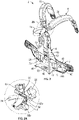
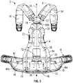
- FIGS. 1-4 show a support assembly 2 for supporting a self-contained breathing apparatus (SCBA) on a user's back.
- SCBA self-contained breathing apparatus
- the SCBA may include other components typically associated with an SCBA such as a pressure air tank or cylinder, at least one pressure regulator, and an inhalation connection, such as a mouthpiece or face mask.
- the pressure air tank, pressure regulator(s), and inhalation connection are not shown in the figures.
- the support assembly 2 generally includes a back frame 4, a waist pad 6, a shoulder harness assembly 8, and a pair of elongate securing members 10, 12.
- the back frame 4 is configured to be positioned adjacent a user's back when the support assembly 2 is worn by the user.
- the back frame 4 is generally rigid and has a unitary (i.e. one-piece) construction.
- the back frame 4 may be formed of sheet metal, such as steel or aluminum, but other light weight high strength materials, such as composites, may be used.
- the back frame 4 includes an upper edge 14, a lower edge 16, a pair of side edges 18, 20, and opposed first and second major surfaces 22, 24.
- the back frame 4 includes a backrest portion 4a and a shelf portion 4b extending outwardly generally perpendicularly from the lower edge 16 of the backrest portion 4a. Configured in this manner, the backrest portion 4a and shelf portion 4b combine to form a generally L-shaped back frame 4.
- the backrest portion 4a includes an upper region 26 for positioning adjacent the upper back of the user, and a lower region 28 for positioning adjacent the lower back of the user when the SCBA support assembly 2 is worn by a user.
- the upper and lower regions 26, 28 are offset (i.e. the backrest portion 4a is not planar). The offset is provided to match the curved profile of a user's back, thereby providing an ergonomic and more comfortable fit for the user.
- the first and second elongate securing members 10, 12 removably secure the waist pad 6 to the lower region 28 of the backrest portion 4b of the back frame 4.
- the first and second elongate securing members 10, 12 may be, for example, generally flat strips of material and/or flexible straps.
- the flexible straps may be formed from a variety of materials including, for example, synthetic plastic materials, natural materials such as leather, metals, and combinations thereof.
- the particular material selected for the straps 10, 12 is not significant to the invention hereof, so long as it provides the desired properties such as adequate strength, durability and heat resistance.
- the flexible straps may comprise woven fabric.
- the flexible straps comprise webbing formed of high strength synthetic aramid fibers, such as Kevlar, Nomex, Technora, and Twaron and combinations thereof.
- suitable materials include polyethylene, polypropylene or polyester, including Dyneema and Spectra, which may be blended or combined with any of the foregoing materials.
- the waist pad 6 may be, for example, a cushioned pad having a front face 38 for contacting the lower back region of the user, and a back face 40 opposite the front face 38.
- the back face 40 of the waist pad 6 includes a reinforced region 42 comprising webbing permanently affixed (e.g. by stitching or adhesively bonded) to the waist pad 6.
- the reinforced region 42 serves to strengthen the region of the waist pad where the first strap 10 is attached, and also serves to distribute the load imparted by the first strap 10 to the waist pad 6 over a larger area.
- the waist pad 6 also includes an adjustable belt 76 for securing the waist pad 6 around the waist of a user.
- the belt 76 may be integrated into, or be provided as part of, the waist pad 6, or it may be provided as one or more separate components that may be removably attached to the ends of the waist belt 6.
- each end of the first strap 10 is removably connected with the back frame 4 and/or waist pad 6.
- each end of the first strap 10 is removably connectable with the waist pad 6.
- each end of the first strap 10 includes a pair of snap fasteners 44a, 46a, 44b, 46b for removably attaching the first strap 10 to the reinforced region 42 of the waist pad 6, thereby allowing the waist pad 6 and back frame 4 to be manually connected and separated without the use of tools.
- Suitable snap fasteners include Pull-the-DOT locking snap fasteners available from Scovill Fasteners, Clarkesville, GA. While snap fasteners have been found to have particular utility for providing the removable connection between the first strap 10 and the waist strap 6, other fasteners, such as clips or slide plates, may also be used.
- the first strap 10 slidably engages the lower region 28 of the back frame 4, thereby permitting a limited degree of side-to-side movement between the waist pad 6 and the back frame 4. More specifically, as shown most clearly in FIG. 1 , the first strap 10 slidably engages a pair of spaced openings 30, 32 contained in the lower region 28 of the backrest portion 4a of the back frame 4. To provide a more secure connection between the first strap 10 and the waist pad 6, the first strap 10 is threaded through a pair of strap loops 80, 82 provided on the back face 40 of the waist pad 6.
- the ends of the strap loops 80, 82 are permanently secured to the back face 40 of the waist pad 6 by, for example, heavy duty box stitching, thereby forming openings through which the first strap 10 is slidably inserted. In this manner, the strap loops 80, 82 serve to removably slidably secure the first strap 10 to the waist pad 6.
- the length and width dimensions of the openings 30, 32 are greater than the width of the first strap 10. This allows freedom of movement between the strap 10 within the openings 30, 32, thereby minimizing the likelihood of pinching and binding, and also reducing wear of the strap 10.
- the back frame 4 includes a longitudinal axis 34, and when the first strap 10 is arranged in its securing position to connect the back frame 4 and the waist pad 6, the first strap 10 extends generally perpendicularly to the back frame longitudinal axis 34 and along the length of the waist pad 6. That is, the openings 30, 32 that slidably receive the first strap 10 are transversely spaced relative to the longitudinal axis 34 of the back frame 4.
- the first strap 10 when the first strap 10 is secured to the back frame 4 and fastened to the waist pad 6, the first strap 10 serves to maintain the waist pad 6 in close proximity to the lower region 28 of the backrest portion 4b of the back frame 4. By doing so, the first strap 10 reduces the likelihood of the second strap 12 inadvertently disconnecting from the back frame 4. In addition, in the unlikely event that the second strap 12 fails or inadvertently becomes disconnected from the back frame 4, the first strap 10 is designed to independently support the load carried by the support assembly 2, thereby providing redundancy for the connection between the back frame 4 and the waist pad 6.
- the second elongate securing member 12 also serves to removably connect the waist pad 6 and the back frame 4.
- the second elongate securing member 12 comprises a second flexible strap having a first end permanently affixed to the waist pad 6.
- the first end is affixed to the waist pad 6 in a region between the two areas where the first strap 10 attaches to the waist pad 6 and between the strap loops 80, 82.
- the second elongate securing member 12 also includes a second free end that extends outwardly away from the waist pad 6 for engagement with the back frame 4.
- the second strap 12 is arranged generally perpendicular to the first strap 10 (i.e. generally parallel to the back frame longitudinal axis 34).
- the first and second straps 10, 12 combine and cooperate to form a flexible connection that provides a joint or pivot point 36 ( FIG. 3 ) between the back frame 4 and waist pad 6 that allows the waist pad 6 to pivot up and down within a predetermined range of motion with respect to the pivot point 36 and the back frame 4. That is, the straps 10, 12 allow the waist pad 6 to pivot or rotate with respect to the back frame 4 as indicated by the arrows 78 shown in FIG. 4 .
- the pivot point 36 is located along the lower edge 16 of the back frame 4 where the second strap 12 contacts the bottom surface of the shelf portion 4b of the back frame 4.
- the free end of the second strap 12 includes a retaining element 48 configured to interlock with a mating slot 50 provided in the shelf portion 4b of the back frame 4.
- the retaining element 48 may be, for example, an I-bar that is manually insertable through the slot 50 and is removably retained therein.
- the back frame 4 further comprises a reinforcing member or bar 52 that extends from the shelf portion 4b to the upper region 26 of the backrest portion 4a. Arranged in this manner, the reinforcing bar 52 and back frame 4 combine to form a truss-like structure capable of safely and securely carrying significant loads.
- the shoulder harness assembly 8 enables the support assembly 2 to be removably secured around the shoulders of the user. Like the waist pad 6, the shoulder harness assembly 8 may be manually connected with and removed from the back frame 4.
- the shoulder harness assembly 8 includes a pair of shoulder pads 54, 56 that are removably connected with the back frame 4. More specifically, each shoulder pad includes an upper end removably connectable with the upper region 26 of the back frame 4 and a lower end removably connectable with the lower region 28 of the back frame 4.
- the upper ends of the shoulder pads 54, 56 include an attachment strap 74 that forms a loop.
- the loop serves as a handle that may be manually grasped by another individual to pull an immobile user wearing the SCBA support assembly 2 to safety.
- the attachment strap 74 includes a retaining device for removably securing the attachment strap 74 to the back frame 4. Suitable retaining devices include, for example, clips, snaps and buckles.
- the retaining device comprises a pair of slide plates 58a, 58b. Suitable slide plates include, for example, Tri-Slide slide plates available from AAA Technology & Specialties Co, Inc. Houston, TX.
- the upper region 26 of the back frame 4 contains a pair of slots 60, 62 for matingly receiving the slide plates 58a, 58b, respectively - best seen in FIG. 2A - thereby providing manually releasable engagement between the upper ends of the shoulder pads 54, 56 and the upper region 26 of the back frame 4.
- the shoulder pads 54, 56 are connected with the upper end of the back frame 4 by manually sliding the slide plates 58a, 58b through the slots 60, 62, respectively.
- the lower slide plate 58b serves as the primary load bearing support
- the upper slide plate 58a tends to bias the shoulder pads 54, 56 outwardly away from the back frame 4, thereby making it easier for the user to put on the backpack assembly 2. That is, when the SCBA support assembly is to be worn by a user, the upper slide plate 58a causes the shoulder pads to "present” to the user, thereby making it easier and faster for the user to don the SCBA support assembly 2.
- the lower ends of the shoulder pads 54, 56 are connected with the lower region 28 of the back frame 4 by an adjustable waist-to-shoulder pad extension strap 64 as partially shown in FIG. 1 .
- the lower ends of the shoulder pads include buckles 66, 68 for slidably and adjustably receiving opposed ends of the waist-to-shoulder pad extension strap 64.
- the waist-to-shoulder pad extension strap 64 slidably engages the angled slots 70, 72 provided in the lower region 28 of the backrest portion 4a along the lower edge 16 of the back frame 4. Arranged in this manner, the waist-to-shoulder pad extension strap 64 may be manually slidably released from the back frame 4.
- waist-to-shoulder pad extension straps may be provided to removably and adjustably secure the lower ends of the shoulder pads 54, 56 with the lower region 28 of the backrest portion 4a of the back frame 4.
- the ends of waist-to-shoulder pad extension straps may include retaining devices (not shown) configured to matingly engage slots 70, 72 provided in the lower region of the back frame, thereby providing manual releasable engagement between the waist-to-shoulder pad extension straps and the lower region of the back frame.
- the retaining devices may be, for example, slide plates similar to slides plates 58a, 58b, although other retaining devices such as clips or snap fasteners may be used.
- each shoulder pad 54, 56 includes a primary portion 54a, 56a and a flap portion 54b, 56b arranged to form a raceway for receiving one or more hoses, tubes, wires, cables, and the like.
- the flap portions 54b, 56b can be arranged in overlapping relation with the primary portion 54a, 54b and include at least one end removably coupled with the primary portion 54a, 56a, thereby providing easy access to the raceway. Configured in this manner allows the shoulder harness assembly 8 to be manually separated from the back frame 4 without tools and without disconnecting any electrical or pneumatic lines (i.e. hoses, tubes, wires or cables).
- the support assembly 2 may further include a pouch 88 for stowing an Emergency Breathing Support System (EBSS).
- the pouch includes a belt loop 90 for slidably receiving the belt 76, as well as a strap loop 92 for slidably receiving the waist-to-shoulder pad extension strap 64. Attaching the pouch to the belt 76 and waist-to-shoulder pad extension strap 64 in this manner provides a range of articulation that allows the pouch 88 to rotate during activities such as reaching overhead, crawling, bending, twisting and sitting. In addition, this attachment configuration allows the EBSS system to be removed from the pouch 88 and separated from both the waist pad 6 and shoulder harness assembly 8 without disconnecting any pneumatic connections.
- EBSS Emergency Breathing Support System
Landscapes
- Health & Medical Sciences (AREA)
- Pulmonology (AREA)
- General Health & Medical Sciences (AREA)
- Business, Economics & Management (AREA)
- Emergency Management (AREA)
- Portable Outdoor Equipment (AREA)
- Respiratory Apparatuses And Protective Means (AREA)
- Professional, Industrial, Or Sporting Protective Garments (AREA)
- Orthopedics, Nursing, And Contraception (AREA)
- Accommodation For Nursing Or Treatment Tables (AREA)
Applications Claiming Priority (2)
| Application Number | Priority Date | Filing Date | Title |
|---|---|---|---|
| US201762573922P | 2017-10-18 | 2017-10-18 | |
| PCT/IB2018/058103 WO2019077549A2 (en) | 2017-10-18 | 2018-10-18 | ARTICULATED SUPPORT ASSEMBLY FOR AUTONOMOUS RESPIRATORY APPARATUS |
Publications (3)
| Publication Number | Publication Date |
|---|---|
| EP3697504A2 EP3697504A2 (en) | 2020-08-26 |
| EP3697504A4 EP3697504A4 (en) | 2021-07-07 |
| EP3697504B1 true EP3697504B1 (en) | 2022-06-29 |
Family
ID=66174342
Family Applications (1)
| Application Number | Title | Priority Date | Filing Date |
|---|---|---|---|
| EP18868120.9A Active EP3697504B1 (en) | 2017-10-18 | 2018-10-18 | Articulating support assembly for a self-contained breathing apparatus |
Country Status (7)
| Country | Link |
|---|---|
| US (1) | US20200238110A1 (enExample) |
| EP (1) | EP3697504B1 (enExample) |
| JP (1) | JP7223751B2 (enExample) |
| CN (1) | CN111246921B (enExample) |
| AR (1) | AR113367A1 (enExample) |
| BR (1) | BR112020007715B1 (enExample) |
| WO (1) | WO2019077549A2 (enExample) |
Families Citing this family (6)
| Publication number | Priority date | Publication date | Assignee | Title |
|---|---|---|---|---|
| GB2563864B (en) * | 2017-06-27 | 2022-01-12 | Draeger Safety Uk Ltd | Harness for breathing apparatus |
| US12214232B1 (en) * | 2020-06-26 | 2025-02-04 | E.D. Bullard Company | Powered air-purifying respirator carriage and assembly |
| KR102506546B1 (ko) * | 2020-11-27 | 2023-03-07 | 변정조 | 공기호흡기 일체형 탈부착 소방용 비상탈출 안전벨트 |
| WO2022141155A1 (en) * | 2020-12-30 | 2022-07-07 | 3M Innovative Properties Company | Self-contained breathing apparatus |
| CN113546343A (zh) * | 2021-08-24 | 2021-10-26 | 泰克曼(南京)电子有限公司 | 防护设备及其便携式电动过滤送风机组件 |
| IL299813B2 (en) * | 2023-01-10 | 2025-05-01 | Caeli Tech Ltd | Quick release for closed-circuit rebreathing |
Family Cites Families (23)
| Publication number | Priority date | Publication date | Assignee | Title |
|---|---|---|---|---|
| US3563431A (en) * | 1968-11-06 | 1971-02-16 | Murray J Pletz | Self-adjusting |
| US5564612A (en) * | 1995-01-27 | 1996-10-15 | Bianchi International | Modular backpack |
| SE505529C2 (sv) * | 1996-02-21 | 1997-09-15 | Comasec International Sa | Bärsele för gasflaska |
| US5954253A (en) * | 1996-06-26 | 1999-09-21 | Johnson Worldwide Associates, Inc. | Flexible frame load carrying system |
| US6966316B2 (en) * | 2002-06-24 | 2005-11-22 | Survivair Respirators, Inc. | Clean gas purge for breathing gas regulator |
| FR2859886B1 (fr) * | 2003-09-22 | 2008-02-22 | Fenzy | Dispositif de fixation rapide pour fixer un dosseret a un porteur |
| KR100553345B1 (ko) * | 2003-11-19 | 2006-02-22 | 주식회사 산청 | 공기통 백마운트용 백팩 |
| US7454800B2 (en) * | 2003-12-30 | 2008-11-25 | 3M Innovative Properties Company | Anatomically fitted respiratory component belt |
| GB0623719D0 (en) * | 2006-11-28 | 2007-01-10 | Draeger Safety Uk Ltd | A harness for use with breathing apparatus |
| US8006877B2 (en) * | 2007-04-18 | 2011-08-30 | Sperian Respiratory Protection Usa, Llc | Backpack for self contained breathing apparatus |
| US8505171B2 (en) * | 2007-04-20 | 2013-08-13 | Fire Innovations Llc | Quick release apparatus for an SCBA frame |
| US8052209B2 (en) * | 2007-08-17 | 2011-11-08 | H.O. Bostrom Company, Inc. | Automatic locking SCBA mounting bracket assembly |
| GB0806359D0 (en) * | 2008-04-08 | 2008-05-14 | Scott Health & Safety Ltd | Carrying system for breathing apparatus |
| WO2012129737A1 (en) * | 2011-04-01 | 2012-10-04 | Shanghai Eagle Safety Equipment Ltd. | Improved rotational waist pad for self contained breathing apparatus harnesses |
| CN104039397A (zh) * | 2012-01-18 | 2014-09-10 | 霍尼韦尔国际公司 | 自给式呼吸装置的人体工程学背板 |
| US8356692B1 (en) * | 2012-03-16 | 2013-01-22 | Mine Safety Appliances Company | Release mechanism for harness system |
| GB201317249D0 (en) * | 2013-09-27 | 2013-11-13 | Scott Health & Safety Ltd | Carrying plate for breathing apparatus |
| US9220333B2 (en) * | 2013-11-27 | 2015-12-29 | Msa Technology, Llc | Adjustable lumbar support for mounting on a backpack and backpack having the same |
| CN204246702U (zh) * | 2014-10-23 | 2015-04-08 | 中国石油天然气股份有限公司 | 呼吸器支架 |
| CA2947977A1 (en) * | 2015-11-09 | 2017-05-09 | Richard L. Denike | Firefighter breathing apparatus pack with integrated rescue equipment |
| CN206103140U (zh) * | 2016-08-30 | 2017-04-19 | 宁波保众应急科技有限公司 | 一种可站立式背板及呼吸器设备 |
| CN107050691B (zh) * | 2017-04-28 | 2023-06-23 | 上海宝亚安全装备股份有限公司 | 一种新型呼吸器装备用具 |
| CN107158596A (zh) * | 2017-06-10 | 2017-09-15 | 上海依民安全装备有限公司 | 一种柔性背托 |
-
2018
- 2018-10-18 EP EP18868120.9A patent/EP3697504B1/en active Active
- 2018-10-18 CN CN201880067471.0A patent/CN111246921B/zh active Active
- 2018-10-18 US US16/639,019 patent/US20200238110A1/en active Pending
- 2018-10-18 AR ARP180103028A patent/AR113367A1/es unknown
- 2018-10-18 JP JP2020521959A patent/JP7223751B2/ja active Active
- 2018-10-18 BR BR112020007715-1A patent/BR112020007715B1/pt active IP Right Grant
- 2018-10-18 WO PCT/IB2018/058103 patent/WO2019077549A2/en not_active Ceased
Also Published As
| Publication number | Publication date |
|---|---|
| JP7223751B2 (ja) | 2023-02-16 |
| EP3697504A2 (en) | 2020-08-26 |
| BR112020007715A2 (pt) | 2020-10-06 |
| BR112020007715B1 (pt) | 2023-11-21 |
| EP3697504A4 (en) | 2021-07-07 |
| US20200238110A1 (en) | 2020-07-30 |
| WO2019077549A3 (en) | 2019-06-13 |
| WO2019077549A2 (en) | 2019-04-25 |
| CN111246921B (zh) | 2022-01-11 |
| CN111246921A (zh) | 2020-06-05 |
| JP2021500122A (ja) | 2021-01-07 |
| AR113367A1 (es) | 2020-04-22 |
Similar Documents
| Publication | Publication Date | Title |
|---|---|---|
| EP3697504B1 (en) | Articulating support assembly for a self-contained breathing apparatus | |
| AU2009235237B2 (en) | Carrying system for breathing apparatus | |
| US9486654B1 (en) | Reconfigurable, modular ergonomic sit harness or saddle | |
| US6398092B1 (en) | Carpenter's belt with lumbosacral support, looped interchangeable pouches, and snaps for suspenders | |
| US5484395A (en) | Fireman's back brace | |
| EP3911420B1 (en) | Safety harness with removable rigid dorsal force-transfer member | |
| US20060102423A1 (en) | Safety harnesses | |
| US8695171B2 (en) | Quick release apparatus for an SCBA frame | |
| US20020074185A1 (en) | Combination trucker's belt and extrication harness | |
| JPH11503050A (ja) | 安全装具 | |
| US20250375630A1 (en) | Web harness system with leg components | |
| AU2018256552A1 (en) | A Personal Lift Assist Apparatus | |
| JP2019162421A (ja) | 背支持フレーム | |
| US20060070799A1 (en) | Harness attached to air tank of self-contained breathing apparatus and provided with added hand loop | |
| US12257462B1 (en) | Victim extraction tool | |
| CA2424778A1 (en) | Improved harness for forest firefighter's equipment | |
| KR200186965Y1 (ko) | 81미리 박격포 짐판 | |
| IT202100025535A1 (it) | Capo indossabile ad uso militare |
Legal Events
| Date | Code | Title | Description |
|---|---|---|---|
| STAA | Information on the status of an ep patent application or granted ep patent |
Free format text: STATUS: THE INTERNATIONAL PUBLICATION HAS BEEN MADE |
|
| PUAI | Public reference made under article 153(3) epc to a published international application that has entered the european phase |
Free format text: ORIGINAL CODE: 0009012 |
|
| STAA | Information on the status of an ep patent application or granted ep patent |
Free format text: STATUS: REQUEST FOR EXAMINATION WAS MADE |
|
| 17P | Request for examination filed |
Effective date: 20200422 |
|
| AK | Designated contracting states |
Kind code of ref document: A2 Designated state(s): AL AT BE BG CH CY CZ DE DK EE ES FI FR GB GR HR HU IE IS IT LI LT LU LV MC MK MT NL NO PL PT RO RS SE SI SK SM TR |
|
| AX | Request for extension of the european patent |
Extension state: BA ME |
|
| DAV | Request for validation of the european patent (deleted) | ||
| DAX | Request for extension of the european patent (deleted) | ||
| A4 | Supplementary search report drawn up and despatched |
Effective date: 20210607 |
|
| RIC1 | Information provided on ipc code assigned before grant |
Ipc: A62B 9/04 20060101AFI20210531BHEP Ipc: A62B 9/02 20060101ALI20210531BHEP Ipc: A62B 25/00 20060101ALI20210531BHEP |
|
| RIC1 | Information provided on ipc code assigned before grant |
Ipc: A45F 3/14 20060101ALI20211202BHEP Ipc: A62B 25/00 20060101ALI20211202BHEP Ipc: A62B 9/02 20060101ALI20211202BHEP Ipc: A62B 9/04 20060101AFI20211202BHEP |
|
| GRAP | Despatch of communication of intention to grant a patent |
Free format text: ORIGINAL CODE: EPIDOSNIGR1 |
|
| STAA | Information on the status of an ep patent application or granted ep patent |
Free format text: STATUS: GRANT OF PATENT IS INTENDED |
|
| INTG | Intention to grant announced |
Effective date: 20220119 |
|
| GRAS | Grant fee paid |
Free format text: ORIGINAL CODE: EPIDOSNIGR3 |
|
| GRAA | (expected) grant |
Free format text: ORIGINAL CODE: 0009210 |
|
| STAA | Information on the status of an ep patent application or granted ep patent |
Free format text: STATUS: THE PATENT HAS BEEN GRANTED |
|
| AK | Designated contracting states |
Kind code of ref document: B1 Designated state(s): AL AT BE BG CH CY CZ DE DK EE ES FI FR GB GR HR HU IE IS IT LI LT LU LV MC MK MT NL NO PL PT RO RS SE SI SK SM TR |
|
| REG | Reference to a national code |
Ref country code: CH Ref legal event code: EP |
|
| REG | Reference to a national code |
Ref country code: AT Ref legal event code: REF Ref document number: 1500905 Country of ref document: AT Kind code of ref document: T Effective date: 20220715 |
|
| REG | Reference to a national code |
Ref country code: IE Ref legal event code: FG4D |
|
| REG | Reference to a national code |
Ref country code: DE Ref legal event code: R096 Ref document number: 602018037444 Country of ref document: DE |
|
| REG | Reference to a national code |
Ref country code: LT Ref legal event code: MG9D |
|
| PG25 | Lapsed in a contracting state [announced via postgrant information from national office to epo] |
Ref country code: SE Free format text: LAPSE BECAUSE OF FAILURE TO SUBMIT A TRANSLATION OF THE DESCRIPTION OR TO PAY THE FEE WITHIN THE PRESCRIBED TIME-LIMIT Effective date: 20220629 Ref country code: NO Free format text: LAPSE BECAUSE OF FAILURE TO SUBMIT A TRANSLATION OF THE DESCRIPTION OR TO PAY THE FEE WITHIN THE PRESCRIBED TIME-LIMIT Effective date: 20220929 Ref country code: LT Free format text: LAPSE BECAUSE OF FAILURE TO SUBMIT A TRANSLATION OF THE DESCRIPTION OR TO PAY THE FEE WITHIN THE PRESCRIBED TIME-LIMIT Effective date: 20220629 Ref country code: HR Free format text: LAPSE BECAUSE OF FAILURE TO SUBMIT A TRANSLATION OF THE DESCRIPTION OR TO PAY THE FEE WITHIN THE PRESCRIBED TIME-LIMIT Effective date: 20220629 Ref country code: GR Free format text: LAPSE BECAUSE OF FAILURE TO SUBMIT A TRANSLATION OF THE DESCRIPTION OR TO PAY THE FEE WITHIN THE PRESCRIBED TIME-LIMIT Effective date: 20220930 Ref country code: FI Free format text: LAPSE BECAUSE OF FAILURE TO SUBMIT A TRANSLATION OF THE DESCRIPTION OR TO PAY THE FEE WITHIN THE PRESCRIBED TIME-LIMIT Effective date: 20220629 Ref country code: BG Free format text: LAPSE BECAUSE OF FAILURE TO SUBMIT A TRANSLATION OF THE DESCRIPTION OR TO PAY THE FEE WITHIN THE PRESCRIBED TIME-LIMIT Effective date: 20220929 |
|
| REG | Reference to a national code |
Ref country code: NL Ref legal event code: MP Effective date: 20220629 |
|
| REG | Reference to a national code |
Ref country code: AT Ref legal event code: MK05 Ref document number: 1500905 Country of ref document: AT Kind code of ref document: T Effective date: 20220629 |
|
| PG25 | Lapsed in a contracting state [announced via postgrant information from national office to epo] |
Ref country code: RS Free format text: LAPSE BECAUSE OF FAILURE TO SUBMIT A TRANSLATION OF THE DESCRIPTION OR TO PAY THE FEE WITHIN THE PRESCRIBED TIME-LIMIT Effective date: 20220629 Ref country code: LV Free format text: LAPSE BECAUSE OF FAILURE TO SUBMIT A TRANSLATION OF THE DESCRIPTION OR TO PAY THE FEE WITHIN THE PRESCRIBED TIME-LIMIT Effective date: 20220629 |
|
| PG25 | Lapsed in a contracting state [announced via postgrant information from national office to epo] |
Ref country code: NL Free format text: LAPSE BECAUSE OF FAILURE TO SUBMIT A TRANSLATION OF THE DESCRIPTION OR TO PAY THE FEE WITHIN THE PRESCRIBED TIME-LIMIT Effective date: 20220629 |
|
| PG25 | Lapsed in a contracting state [announced via postgrant information from national office to epo] |
Ref country code: SM Free format text: LAPSE BECAUSE OF FAILURE TO SUBMIT A TRANSLATION OF THE DESCRIPTION OR TO PAY THE FEE WITHIN THE PRESCRIBED TIME-LIMIT Effective date: 20220629 Ref country code: SK Free format text: LAPSE BECAUSE OF FAILURE TO SUBMIT A TRANSLATION OF THE DESCRIPTION OR TO PAY THE FEE WITHIN THE PRESCRIBED TIME-LIMIT Effective date: 20220629 Ref country code: RO Free format text: LAPSE BECAUSE OF FAILURE TO SUBMIT A TRANSLATION OF THE DESCRIPTION OR TO PAY THE FEE WITHIN THE PRESCRIBED TIME-LIMIT Effective date: 20220629 Ref country code: PT Free format text: LAPSE BECAUSE OF FAILURE TO SUBMIT A TRANSLATION OF THE DESCRIPTION OR TO PAY THE FEE WITHIN THE PRESCRIBED TIME-LIMIT Effective date: 20221031 Ref country code: ES Free format text: LAPSE BECAUSE OF FAILURE TO SUBMIT A TRANSLATION OF THE DESCRIPTION OR TO PAY THE FEE WITHIN THE PRESCRIBED TIME-LIMIT Effective date: 20220629 Ref country code: EE Free format text: LAPSE BECAUSE OF FAILURE TO SUBMIT A TRANSLATION OF THE DESCRIPTION OR TO PAY THE FEE WITHIN THE PRESCRIBED TIME-LIMIT Effective date: 20220629 Ref country code: AT Free format text: LAPSE BECAUSE OF FAILURE TO SUBMIT A TRANSLATION OF THE DESCRIPTION OR TO PAY THE FEE WITHIN THE PRESCRIBED TIME-LIMIT Effective date: 20220629 |
|
| PG25 | Lapsed in a contracting state [announced via postgrant information from national office to epo] |
Ref country code: PL Free format text: LAPSE BECAUSE OF FAILURE TO SUBMIT A TRANSLATION OF THE DESCRIPTION OR TO PAY THE FEE WITHIN THE PRESCRIBED TIME-LIMIT Effective date: 20220629 Ref country code: IS Free format text: LAPSE BECAUSE OF FAILURE TO SUBMIT A TRANSLATION OF THE DESCRIPTION OR TO PAY THE FEE WITHIN THE PRESCRIBED TIME-LIMIT Effective date: 20221029 |
|
| REG | Reference to a national code |
Ref country code: DE Ref legal event code: R097 Ref document number: 602018037444 Country of ref document: DE |
|
| PG25 | Lapsed in a contracting state [announced via postgrant information from national office to epo] |
Ref country code: AL Free format text: LAPSE BECAUSE OF FAILURE TO SUBMIT A TRANSLATION OF THE DESCRIPTION OR TO PAY THE FEE WITHIN THE PRESCRIBED TIME-LIMIT Effective date: 20220629 |
|
| PG25 | Lapsed in a contracting state [announced via postgrant information from national office to epo] |
Ref country code: DK Free format text: LAPSE BECAUSE OF FAILURE TO SUBMIT A TRANSLATION OF THE DESCRIPTION OR TO PAY THE FEE WITHIN THE PRESCRIBED TIME-LIMIT Effective date: 20220629 Ref country code: CZ Free format text: LAPSE BECAUSE OF FAILURE TO SUBMIT A TRANSLATION OF THE DESCRIPTION OR TO PAY THE FEE WITHIN THE PRESCRIBED TIME-LIMIT Effective date: 20220629 |
|
| PLBE | No opposition filed within time limit |
Free format text: ORIGINAL CODE: 0009261 |
|
| STAA | Information on the status of an ep patent application or granted ep patent |
Free format text: STATUS: NO OPPOSITION FILED WITHIN TIME LIMIT |
|
| PG25 | Lapsed in a contracting state [announced via postgrant information from national office to epo] |
Ref country code: MC Free format text: LAPSE BECAUSE OF FAILURE TO SUBMIT A TRANSLATION OF THE DESCRIPTION OR TO PAY THE FEE WITHIN THE PRESCRIBED TIME-LIMIT Effective date: 20220629 |
|
| REG | Reference to a national code |
Ref country code: CH Ref legal event code: PL |
|
| 26N | No opposition filed |
Effective date: 20230330 |
|
| REG | Reference to a national code |
Ref country code: BE Ref legal event code: MM Effective date: 20221031 |
|
| PG25 | Lapsed in a contracting state [announced via postgrant information from national office to epo] |
Ref country code: LU Free format text: LAPSE BECAUSE OF NON-PAYMENT OF DUE FEES Effective date: 20221018 |
|
| P01 | Opt-out of the competence of the unified patent court (upc) registered |
Effective date: 20230530 |
|
| PG25 | Lapsed in a contracting state [announced via postgrant information from national office to epo] |
Ref country code: LI Free format text: LAPSE BECAUSE OF NON-PAYMENT OF DUE FEES Effective date: 20221031 Ref country code: FR Free format text: LAPSE BECAUSE OF NON-PAYMENT OF DUE FEES Effective date: 20221031 Ref country code: CH Free format text: LAPSE BECAUSE OF NON-PAYMENT OF DUE FEES Effective date: 20221031 |
|
| PG25 | Lapsed in a contracting state [announced via postgrant information from national office to epo] |
Ref country code: SI Free format text: LAPSE BECAUSE OF FAILURE TO SUBMIT A TRANSLATION OF THE DESCRIPTION OR TO PAY THE FEE WITHIN THE PRESCRIBED TIME-LIMIT Effective date: 20220629 |
|
| PG25 | Lapsed in a contracting state [announced via postgrant information from national office to epo] |
Ref country code: BE Free format text: LAPSE BECAUSE OF NON-PAYMENT OF DUE FEES Effective date: 20221031 |
|
| PG25 | Lapsed in a contracting state [announced via postgrant information from national office to epo] |
Ref country code: IE Free format text: LAPSE BECAUSE OF NON-PAYMENT OF DUE FEES Effective date: 20221018 |
|
| PG25 | Lapsed in a contracting state [announced via postgrant information from national office to epo] |
Ref country code: IT Free format text: LAPSE BECAUSE OF FAILURE TO SUBMIT A TRANSLATION OF THE DESCRIPTION OR TO PAY THE FEE WITHIN THE PRESCRIBED TIME-LIMIT Effective date: 20220629 |
|
| PG25 | Lapsed in a contracting state [announced via postgrant information from national office to epo] |
Ref country code: CY Free format text: LAPSE BECAUSE OF FAILURE TO SUBMIT A TRANSLATION OF THE DESCRIPTION OR TO PAY THE FEE WITHIN THE PRESCRIBED TIME-LIMIT Effective date: 20220629 |
|
| PG25 | Lapsed in a contracting state [announced via postgrant information from national office to epo] |
Ref country code: MK Free format text: LAPSE BECAUSE OF FAILURE TO SUBMIT A TRANSLATION OF THE DESCRIPTION OR TO PAY THE FEE WITHIN THE PRESCRIBED TIME-LIMIT Effective date: 20220629 Ref country code: HU Free format text: LAPSE BECAUSE OF FAILURE TO SUBMIT A TRANSLATION OF THE DESCRIPTION OR TO PAY THE FEE WITHIN THE PRESCRIBED TIME-LIMIT; INVALID AB INITIO Effective date: 20181018 |
|
| PG25 | Lapsed in a contracting state [announced via postgrant information from national office to epo] |
Ref country code: MT Free format text: LAPSE BECAUSE OF FAILURE TO SUBMIT A TRANSLATION OF THE DESCRIPTION OR TO PAY THE FEE WITHIN THE PRESCRIBED TIME-LIMIT Effective date: 20220629 |
|
| PG25 | Lapsed in a contracting state [announced via postgrant information from national office to epo] |
Ref country code: BG Free format text: LAPSE BECAUSE OF FAILURE TO SUBMIT A TRANSLATION OF THE DESCRIPTION OR TO PAY THE FEE WITHIN THE PRESCRIBED TIME-LIMIT Effective date: 20220629 |
|
| PG25 | Lapsed in a contracting state [announced via postgrant information from national office to epo] |
Ref country code: BG Free format text: LAPSE BECAUSE OF FAILURE TO SUBMIT A TRANSLATION OF THE DESCRIPTION OR TO PAY THE FEE WITHIN THE PRESCRIBED TIME-LIMIT Effective date: 20220629 |
|
| PGFP | Annual fee paid to national office [announced via postgrant information from national office to epo] |
Ref country code: DE Payment date: 20240919 Year of fee payment: 7 |
|
| PGFP | Annual fee paid to national office [announced via postgrant information from national office to epo] |
Ref country code: GB Payment date: 20250923 Year of fee payment: 8 |
|
| PG25 | Lapsed in a contracting state [announced via postgrant information from national office to epo] |
Ref country code: TR Free format text: LAPSE BECAUSE OF FAILURE TO SUBMIT A TRANSLATION OF THE DESCRIPTION OR TO PAY THE FEE WITHIN THE PRESCRIBED TIME-LIMIT Effective date: 20220629 |