EP3697356B1 - Customized ophthalmic surgical profiles - Google Patents
Customized ophthalmic surgical profiles Download PDFInfo
- Publication number
- EP3697356B1 EP3697356B1 EP18786051.5A EP18786051A EP3697356B1 EP 3697356 B1 EP3697356 B1 EP 3697356B1 EP 18786051 A EP18786051 A EP 18786051A EP 3697356 B1 EP3697356 B1 EP 3697356B1
- Authority
- EP
- European Patent Office
- Prior art keywords
- pattern
- surgical
- laser
- customized
- ophthalmic surgical
- Prior art date
- Legal status (The legal status is an assumption and is not a legal conclusion. Google has not performed a legal analysis and makes no representation as to the accuracy of the status listed.)
- Active
Links
- 238000010200 validation analysis Methods 0.000 claims description 79
- 238000000034 method Methods 0.000 claims description 55
- 238000004088 simulation Methods 0.000 claims description 29
- 238000004590 computer program Methods 0.000 claims description 19
- 238000012795 verification Methods 0.000 claims description 10
- 238000013467 fragmentation Methods 0.000 claims description 5
- 238000006062 fragmentation reaction Methods 0.000 claims description 5
- 238000013461 design Methods 0.000 description 63
- 238000012800 visualization Methods 0.000 description 20
- 230000008569 process Effects 0.000 description 18
- 238000012014 optical coherence tomography Methods 0.000 description 13
- 238000010586 diagram Methods 0.000 description 10
- 238000012545 processing Methods 0.000 description 8
- 238000002679 ablation Methods 0.000 description 7
- 238000007726 management method Methods 0.000 description 7
- 230000004048 modification Effects 0.000 description 6
- 238000012986 modification Methods 0.000 description 6
- 230000003287 optical effect Effects 0.000 description 6
- 238000001356 surgical procedure Methods 0.000 description 6
- 238000004891 communication Methods 0.000 description 5
- 238000003384 imaging method Methods 0.000 description 5
- 230000008901 benefit Effects 0.000 description 4
- 238000013515 script Methods 0.000 description 4
- 238000005457 optimization Methods 0.000 description 3
- 208000002177 Cataract Diseases 0.000 description 2
- 238000011161 development Methods 0.000 description 2
- 230000006870 function Effects 0.000 description 2
- 230000000644 propagated effect Effects 0.000 description 2
- 238000011282 treatment Methods 0.000 description 2
- 230000001133 acceleration Effects 0.000 description 1
- 230000004075 alteration Effects 0.000 description 1
- 210000002159 anterior chamber Anatomy 0.000 description 1
- 238000004422 calculation algorithm Methods 0.000 description 1
- 239000002775 capsule Substances 0.000 description 1
- 230000001413 cellular effect Effects 0.000 description 1
- 238000012790 confirmation Methods 0.000 description 1
- 210000004087 cornea Anatomy 0.000 description 1
- 238000005553 drilling Methods 0.000 description 1
- 238000010304 firing Methods 0.000 description 1
- 230000003993 interaction Effects 0.000 description 1
- 238000005305 interferometry Methods 0.000 description 1
- 238000013532 laser treatment Methods 0.000 description 1
- 230000006855 networking Effects 0.000 description 1
- 239000013307 optical fiber Substances 0.000 description 1
- 230000001737 promoting effect Effects 0.000 description 1
- 238000009877 rendering Methods 0.000 description 1
- 230000004044 response Effects 0.000 description 1
- 230000002207 retinal effect Effects 0.000 description 1
- 239000000758 substrate Substances 0.000 description 1
Images

Classifications
-
- A—HUMAN NECESSITIES
- A61—MEDICAL OR VETERINARY SCIENCE; HYGIENE
- A61F—FILTERS IMPLANTABLE INTO BLOOD VESSELS; PROSTHESES; DEVICES PROVIDING PATENCY TO, OR PREVENTING COLLAPSING OF, TUBULAR STRUCTURES OF THE BODY, e.g. STENTS; ORTHOPAEDIC, NURSING OR CONTRACEPTIVE DEVICES; FOMENTATION; TREATMENT OR PROTECTION OF EYES OR EARS; BANDAGES, DRESSINGS OR ABSORBENT PADS; FIRST-AID KITS
- A61F9/00—Methods or devices for treatment of the eyes; Devices for putting-in contact lenses; Devices to correct squinting; Apparatus to guide the blind; Protective devices for the eyes, carried on the body or in the hand
- A61F9/007—Methods or devices for eye surgery
- A61F9/008—Methods or devices for eye surgery using laser
-
- G—PHYSICS
- G16—INFORMATION AND COMMUNICATION TECHNOLOGY [ICT] SPECIALLY ADAPTED FOR SPECIFIC APPLICATION FIELDS
- G16H—HEALTHCARE INFORMATICS, i.e. INFORMATION AND COMMUNICATION TECHNOLOGY [ICT] SPECIALLY ADAPTED FOR THE HANDLING OR PROCESSING OF MEDICAL OR HEALTHCARE DATA
- G16H50/00—ICT specially adapted for medical diagnosis, medical simulation or medical data mining; ICT specially adapted for detecting, monitoring or modelling epidemics or pandemics
- G16H50/50—ICT specially adapted for medical diagnosis, medical simulation or medical data mining; ICT specially adapted for detecting, monitoring or modelling epidemics or pandemics for simulation or modelling of medical disorders
-
- A—HUMAN NECESSITIES
- A61—MEDICAL OR VETERINARY SCIENCE; HYGIENE
- A61B—DIAGNOSIS; SURGERY; IDENTIFICATION
- A61B34/00—Computer-aided surgery; Manipulators or robots specially adapted for use in surgery
- A61B34/10—Computer-aided planning, simulation or modelling of surgical operations
-
- A—HUMAN NECESSITIES
- A61—MEDICAL OR VETERINARY SCIENCE; HYGIENE
- A61F—FILTERS IMPLANTABLE INTO BLOOD VESSELS; PROSTHESES; DEVICES PROVIDING PATENCY TO, OR PREVENTING COLLAPSING OF, TUBULAR STRUCTURES OF THE BODY, e.g. STENTS; ORTHOPAEDIC, NURSING OR CONTRACEPTIVE DEVICES; FOMENTATION; TREATMENT OR PROTECTION OF EYES OR EARS; BANDAGES, DRESSINGS OR ABSORBENT PADS; FIRST-AID KITS
- A61F9/00—Methods or devices for treatment of the eyes; Devices for putting-in contact lenses; Devices to correct squinting; Apparatus to guide the blind; Protective devices for the eyes, carried on the body or in the hand
- A61F9/007—Methods or devices for eye surgery
- A61F9/008—Methods or devices for eye surgery using laser
- A61F9/00825—Methods or devices for eye surgery using laser for photodisruption
-
- G—PHYSICS
- G06—COMPUTING; CALCULATING OR COUNTING
- G06F—ELECTRIC DIGITAL DATA PROCESSING
- G06F9/00—Arrangements for program control, e.g. control units
- G06F9/06—Arrangements for program control, e.g. control units using stored programs, i.e. using an internal store of processing equipment to receive or retain programs
- G06F9/44—Arrangements for executing specific programs
- G06F9/455—Emulation; Interpretation; Software simulation, e.g. virtualisation or emulation of application or operating system execution engines
-
- A—HUMAN NECESSITIES
- A61—MEDICAL OR VETERINARY SCIENCE; HYGIENE
- A61B—DIAGNOSIS; SURGERY; IDENTIFICATION
- A61B34/00—Computer-aided surgery; Manipulators or robots specially adapted for use in surgery
- A61B34/10—Computer-aided planning, simulation or modelling of surgical operations
- A61B2034/101—Computer-aided simulation of surgical operations
- A61B2034/102—Modelling of surgical devices, implants or prosthesis
- A61B2034/104—Modelling the effect of the tool, e.g. the effect of an implanted prosthesis or for predicting the effect of ablation or burring
-
- A—HUMAN NECESSITIES
- A61—MEDICAL OR VETERINARY SCIENCE; HYGIENE
- A61F—FILTERS IMPLANTABLE INTO BLOOD VESSELS; PROSTHESES; DEVICES PROVIDING PATENCY TO, OR PREVENTING COLLAPSING OF, TUBULAR STRUCTURES OF THE BODY, e.g. STENTS; ORTHOPAEDIC, NURSING OR CONTRACEPTIVE DEVICES; FOMENTATION; TREATMENT OR PROTECTION OF EYES OR EARS; BANDAGES, DRESSINGS OR ABSORBENT PADS; FIRST-AID KITS
- A61F9/00—Methods or devices for treatment of the eyes; Devices for putting-in contact lenses; Devices to correct squinting; Apparatus to guide the blind; Protective devices for the eyes, carried on the body or in the hand
- A61F9/007—Methods or devices for eye surgery
- A61F9/008—Methods or devices for eye surgery using laser
- A61F2009/00861—Methods or devices for eye surgery using laser adapted for treatment at a particular location
- A61F2009/0087—Lens
-
- A—HUMAN NECESSITIES
- A61—MEDICAL OR VETERINARY SCIENCE; HYGIENE
- A61F—FILTERS IMPLANTABLE INTO BLOOD VESSELS; PROSTHESES; DEVICES PROVIDING PATENCY TO, OR PREVENTING COLLAPSING OF, TUBULAR STRUCTURES OF THE BODY, e.g. STENTS; ORTHOPAEDIC, NURSING OR CONTRACEPTIVE DEVICES; FOMENTATION; TREATMENT OR PROTECTION OF EYES OR EARS; BANDAGES, DRESSINGS OR ABSORBENT PADS; FIRST-AID KITS
- A61F9/00—Methods or devices for treatment of the eyes; Devices for putting-in contact lenses; Devices to correct squinting; Apparatus to guide the blind; Protective devices for the eyes, carried on the body or in the hand
- A61F9/007—Methods or devices for eye surgery
- A61F9/008—Methods or devices for eye surgery using laser
- A61F2009/00861—Methods or devices for eye surgery using laser adapted for treatment at a particular location
- A61F2009/00872—Cornea
-
- A—HUMAN NECESSITIES
- A61—MEDICAL OR VETERINARY SCIENCE; HYGIENE
- A61F—FILTERS IMPLANTABLE INTO BLOOD VESSELS; PROSTHESES; DEVICES PROVIDING PATENCY TO, OR PREVENTING COLLAPSING OF, TUBULAR STRUCTURES OF THE BODY, e.g. STENTS; ORTHOPAEDIC, NURSING OR CONTRACEPTIVE DEVICES; FOMENTATION; TREATMENT OR PROTECTION OF EYES OR EARS; BANDAGES, DRESSINGS OR ABSORBENT PADS; FIRST-AID KITS
- A61F9/00—Methods or devices for treatment of the eyes; Devices for putting-in contact lenses; Devices to correct squinting; Apparatus to guide the blind; Protective devices for the eyes, carried on the body or in the hand
- A61F9/007—Methods or devices for eye surgery
- A61F9/008—Methods or devices for eye surgery using laser
- A61F2009/00885—Methods or devices for eye surgery using laser for treating a particular disease
- A61F2009/00887—Cataract
-
- A—HUMAN NECESSITIES
- A61—MEDICAL OR VETERINARY SCIENCE; HYGIENE
- A61F—FILTERS IMPLANTABLE INTO BLOOD VESSELS; PROSTHESES; DEVICES PROVIDING PATENCY TO, OR PREVENTING COLLAPSING OF, TUBULAR STRUCTURES OF THE BODY, e.g. STENTS; ORTHOPAEDIC, NURSING OR CONTRACEPTIVE DEVICES; FOMENTATION; TREATMENT OR PROTECTION OF EYES OR EARS; BANDAGES, DRESSINGS OR ABSORBENT PADS; FIRST-AID KITS
- A61F9/00—Methods or devices for treatment of the eyes; Devices for putting-in contact lenses; Devices to correct squinting; Apparatus to guide the blind; Protective devices for the eyes, carried on the body or in the hand
- A61F9/007—Methods or devices for eye surgery
- A61F9/008—Methods or devices for eye surgery using laser
- A61F2009/00897—Scanning mechanisms or algorithms
Definitions
- the present disclosure relates to surgical devices, and in particular ophthalmic surgical laser systems.
- Laser-based surgical systems are used to perform numerous ophthalmic procedures.
- the LenSx ® Laser manufactured by Alcon ® is a femtosecond laser system capable of producing precise, image-guided incisions on every plane of the anterior chamber of the eye, including the cornea, capsule, and lens.
- Other examples include the WaveLight ® FS200 and EX500, both of which are manufactured by Alcon ® , as well as cataract and refractive surgical lasers manufactured by other companies.
- a system for defining cuts in eye tissue which is configured to store eye data which defines a three-dimensional model of the eye.
- the system further includes a cut surface editor for defining and positioning cut surfaces in the three-dimensional model of the eye based on user instructions and a cut pattern generator for, based on the positioned cut surfaces, generating and storing three-dimensional cut patterns for defining tissue cuts to be executed in a human eye by means of a femtosecond laser.
- a cut simulator is configured to simulate, based on the eye data and the stored three-dimensional cut patterns, execution of the tissue cuts defined by a three-dimensional cut pattern, and to visualize it on a display.
- a cut pattern editor is provided which is configured to adapt, based on user instructions, the stored three-dimensional cut pattern, e.g. by changing a cut surface and/or cut direction.
- WO 2015/070092 A1 discloses another system and method for determining a vision treatment for an eye of a patient where an original target profile for the eye of the patient is received, the original target profile is modified so as to generate a modified target profile, and the vision treatment is determined based on the modified target profile.
- EP 2 361 068 A1 relates to an apparatus, an algorithm and a method for providing a laser shot file for use in a laser. The shot file may be applied for performing a refractive laser treatment of an eye or for producing a customized contact lens or an intraocular lens.
- WO 2016/061511 A1 discloses another laser eye surgery system and a method for treating an object with a laser beam based on a generated laser fragmentation pattern.
- a method of validating a customized ophthalmic surgical profile, an ophthalmic surgical computer program stored on a non-transitory computer-readable medium and a system with the features of the independent claims are provided.
- a method includes obtaining a customized ophthalmic surgical profile.
- the customized ophthalmic surgical profile includes a surgical pattern and at least one parameter associated with the surgical pattern.
- the method also includes generating, based on the customized ophthalmic surgical profile, a pattern definition file executable by a laser-based ophthalmic surgical system, and simulating, based on the pattern definition file, execution of the customized ophthalmic surgical profile on the laser-based ophthalmic surgical system.
- the method further includes validating the pattern definition file based on an output of the simulation, and providing the validated pattern definition file for execution on the laser-based ophthalmic surgical system, wherein simulating execution of the customized surgical profile comprises: calculating laser scan coordinates for the customized laser surgical profile; and determining a laser pulse energy for each of the scan coordinates, and wherein validating the pattern definition file comprises: calculating a surgical volume, total energy, and procedure time of the simulate application of the customized surgical laser profile; and determining whether the surgical volume, total energy, and procedure time comply with predetermined thresholds.
- an ophthalmic surgical computer program is stored on a non-transitory computer-readable medium, and includes a pattern definition engine, a pattern simulation engine, a pattern validation engine and a pattern viewer engine.
- the pattern definition engine is configured to obtain a customized ophthalmic surgical profile that includes a surgical pattern and at least one parameter associated with the surgical pattern, and generate, based on the customized ophthalmic surgical profile, a pattern definition file executable by a laser-based ophthalmic surgical system.
- the pattern simulation engine is configured to simulate, based on the pattern definition file, execution of the customized ophthalmic surgical profile on the laser-based ophthalmic surgical system.
- the pattern validation engine is configured to validate the pattern definition file based on an output of the simulation.
- the pattern viewer engine configured to generate a representation of at least one of the customized ophthalmic surgical profile and results of simulated execution of the customized ophthalmic surgical profile to a user; wherein the pattern simulation engine is configured to: calculate laser scan coordinates for the surgical pattern; and determine a laser pulse energy for each of the scan coordinates; wherein the pattern validation engine is configured to: calculate a surgical volume, total energy, and procedure time of the simulated application of the customized surgical laser pattern; and determine whether the surgical volume, total energy, and procedure time comply with predetermined thresholds.
- a system includes one or more processors and a memory that includes instructions.
- the instructions are operable, when executed by the one or more processors, to obtain a customized ophthalmic surgical profile that includes a surgical pattern and at least one parameter associated with the surgical pattern, and generate, based on the customized ophthalmic surgical profile, a pattern definition file executable by a laser-based ophthalmic surgical system.
- the instructions are also operable to simulate, based on the pattern definition file, execution of the customized ophthalmic surgical profile on the laser-based ophthalmic surgical system, validate the pattern definition file based on an output of the simulation, and provide the validated pattern definition file for execution on the laser-based ophthalmic surgical system.
- a display may be operable to provide a representation of at least one of the customized ophthalmic surgical profile and results of simulated execution of the customized ophthalmic surgical profile to a user.
- the instructions for simulating execution of the customized ophthalmic surgical profile are operable to: calculate laser scan coordinates for the customized laser surgical pattern; and determine a laser pulse energy for each of the scan coordinates, characterized in that the instructions for validating the pattern definition file are operable to: calculate a surgical volume, total energy, and procedure time of the simulated application of the customized surgical laser pattern; and determine whether the surgical volume, total energy, and procedure time comply with predetermined thresholds.
- surgical patterns and parameters for a laser-based ophthalmic surgical system may be modified or otherwise customized.
- operators of the system e.g., surgeons
- the custom surgical patterns and parameters may be validated, such as by a third party (e.g., the manufacturer of the surgical system), to ensure the patterns and parameters may be safely and properly executed by a target surgical system.
- validated surgical patterns and parameters may be stored in a repository and shared with other surgical system operators.
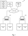
- FIG. 1 is a block diagram of an example surgical profile validation system 100.
- the example system 100 comprises multiple target surgical systems 102 that are communicatively coupled to pattern design systems 104.
- the target surgical systems 102 and the pattern design systems 104 are also communicatively coupled to a pattern validation system 108 and a pattern repository 110 through the network 106.
- the network 106 may include via any suitable combination of wired and/or wireless networks (e.g., Ethernet, optical fiber, IEEE 802.11, cellular, Internet, etc.).
- the target systems 102 and the pattern design systems 104 may be managed by a clinic, and may be co-located or distributed in different geographic locations.
- the target systems 102A, 102B and the pattern design system 104A may be associated with a first clinic, and the target systems 102C, 102D and the pattern design system 104B may be associated with a second clinic.
- the system 100 may include additional pattern design systems 104 and target systems 102 communicatively coupled to the pattern validation system 108 and the pattern repository 110, that are associated with one or more clinics.
- the target surgical systems 102 may include any suitable surgical system.
- each of the target surgical systems 102 is a laser-based ophthalmic surgical system that is suitable for performing refractive, cataract, vitro retinal, or other ophthalmic surgical procedures.
- the laser-based ophthalmic surgical system may include a laser system (e.g., a femtosecond, picosecond, or excimer laser system) along with other optical components (e.g., lenses, mirrors, or diffraction gratings) that direct pulses from the laser to pre-determined locations within a patient's eye.
- the target surgical systems 102 includes a laser system configured to generate a pulsed laser beam, scanning optical elements configured to scan the pulsed laser beam in three dimensions, and a laser controller configured to execute a pattern definition file to control the laser system and the scanning optical elements according to a customized surgical profile defined by the pattern definition file.
- each of the target systems 102 may be a LenSx ® system or a WaveLight ® FS200 or EX500 system.
- the pattern design systems 104 may include any suitable system for designing or customizing a surgical profile for execution on a target surgical system 102.
- a customized surgical profile may comprise a set of scan patterns, incisions, shapes, and laser energy parameters, pulse duration parameters, repetition rate parameters, and the like, which collectively define and control how a surgical laser and associated components perform a specific laser surgical procedure.
- a customized surgical profile may be embodied in a pattern definition file, as described herein.
- the pattern design systems 104 may be computer systems (e.g., a server, PC, laptop, tablet, or other computer or mobile device) that run an operating system (e.g., Windows, Linux, macOS, iOS, Android, etc.) and execute stored computer programs that allow a user to design a customized surgical profile (which may be embodied as a file or data stored on non-transitory computer readable medium) by, for example, selecting or modifying one or more surgical patterns, shapes, or parameters related to a surgical procedure to be performed on a target surgical system 102.
- the computer programs may include one or more software modules or engines encoded with logic to provide various functionalities related to designing a customized surgical profile.
- the computer program may include one or more of the software engines described below with respect to the pattern design system 210 of FIG. 2 .
- the pattern validation system 108 may include any suitable system for validating a customized surgical profile created using a pattern design system 104.
- the pattern validation system 108 may be a computer system (e.g., a server, PC, laptop, tablet, or other computer or mobile device) that runs an operating system (e.g., Windows, Linux, macOS, iOS, Android, etc.) and executes stored computer programs that simulate execution of the customized surgical profile, validate the safety and efficacy pattern based on the simulation, and provide a validated pattern definition file for execution on a target surgical system 102.
- the computer programs may include one or more software modules or engines that provide various functionalities related to the validation of a customized surgical profile created by a pattern design system 104.
- the computer program may include one or more of the software engines described below with respect to the pattern design system 210 of FIG. 2 .
- the pattern validation system 108 may also include a licensing module operable to verify licenses, permissions, or other information associated with the pattern design systems 104 during the validation (e.g., to ensure the pattern design system 104 is authorized to customize surgical profiles and submit the profiles for validation).
- target system 102 or pattern design system 104 may send a validation and license verification request that includes an identifier or credentials for the target system or the operator and a pattern definition file identifier to pattern validation system 108.
- a validation module of validation system 108 may execute a process to validate that the selected pattern definition file is safe and effective for use by the target system 102.
- the validation request may, in some examples, include patient-specific information (e.g., eye biometry data, OCT image data, risk factor data, etc.), and the validation module may run a validation process to confirm that the selected pattern definition file is safe and effective for use by the target system 102 based on patient-specific information.
- the licensing module of validation system 108 may authenticate (e.g., by comparing information in the validation and license verification request with information in a database storing operator license data) the requesting operator or target system, for example, by determining whether the operator or target system is currently licensed or otherwise has permission to execute the selected pattern definition file.
- the licensing module may send a confirmation to target system 102, allowing it to proceed with the selected pattern definition file. If the validation request or license check is not confirmed, the licensing module may send a denial to target system 102. In some embodiments, the denial may include an explanation of why the validation request or license check was not confirmed, and may initiate a process by which the operator of target system 102 may modify the pattern definition file to pass the validation check or obtain a license (e.g., by submitting a single-use, multi-use, or subscription license fee. Accordingly, in some implementations, the customized surgical profile may not be executable on a target surgical system 102 (e.g., on an actual patient) until the pattern validation system 108 has validated the pattern definition file and confirmed that the user has a license to use it.
- a target surgical system 102 e.g., on an actual patient
- Surgical profiles that have been validated by the pattern validation system 108 may be stored in the pattern repository 110.
- Target surgical systems 102 can access and execute validated surgical profiles stored in the pattern repository 110.
- a surgical profile may initially be designed by the pattern design system 104A for execution on the target surgical system 102A.
- the target surgical system 102A may access the pattern from the pattern repository 110 and execute the pattern on a patient.
- the target surgical system 102A may access and execute the same pattern stored in the pattern repository 110 on another patient.
- the target surgical systems 102B, 102C, 102D may access and execute the same pattern stored in the pattern repository 110 on another patient.
- pattern validation system 108 may re-validate a pattern definition file for individuals based on patient-specific data before allowing the pattern to be executed by a surgical system 102.
- the pattern validation system 108 includes a processor 112, a memory 114, and an interface 116.
- the example processor 112 executes instructions, for example, to generate output data based on data inputs.
- the instructions can include programs, codes, scripts, or other types of data stored in memory. Additionally or alternatively, the instructions can be encoded as pre-programmed or re-programmable logic circuits, logic gates, or other types of hardware or firmware components.
- the processor 112 may be or include a general purpose microprocessor, as well as a specialized co-processor or another type of data processing apparatus. In some cases, the processor 112 performs high level operation of the pattern validation system 108.
- the processor 112 may be configured to execute or interpret software, scripts, programs, functions, executables, or other instructions stored in the memory 114 to simulate execution of a customized pattern definition file and validate the pattern definition file based on the simulation (e.g., as described below in the process 400 of FIG. 4 ).
- the processor 112 includes multiple processors.
- the example memory 114 includes computer-readable media, for example, a volatile memory device, a non-volatile memory device, or both.
- the memory 114 can include one or more read-only memory devices, random-access memory devices, buffer memory devices, or a combination of these and other types of memory devices.
- the memory 114 may store instructions that are executable by the processor 112.
- the instructions may include instructions for simulating execution of a customized pattern definition file and validating the pattern definition file based on the simulation (e.g., as described below in the process 400 of FIG. 4 ).
- the example interface 116 provides communication between the pattern validation system 108 and one or more other devices.
- the interface 116 may include a network interface (e.g., a wireless interface or a wired interface) operable to communication with one or more of the pattern design systems 104 over the network 106.
- the interface 116 may also include interfaces allowing interaction with the pattern validation system 108 by a user, such as a keyboard, mouse, touchscreen, and the like.
- the example system 100 may include additional, fewer, or different components from those shown in FIG. 1 , in certain embodiments.
- the system 100 can include different types of target surgical systems 102 (e.g., different types or models of laser-based ophthalmic surgical systems).
- components of the system 100 may be portions of the same system, in certain embodiments.
- the pattern validation system 108 and the pattern repository 110 may comprise logical portions of the same computer system.
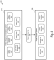
- FIG. 2 is a block diagram illustrating the architecture of an example surgical profile design system 200.
- the example surgical profile design system includes software engines that make up an ophthalmic surgical computer program designed for execution by one or more computers running an operating system.
- the example surgical profile design system 200 includes a pattern design and validation system 210 and a target surgical system 230.
- the pattern design and validation system 210 generates and validates a pattern definition file 220 that is provided for execution on the target surgical system 230.
- the pattern definition file 220 may be system-agnostic, in that it may be executed on one or more different types or models of target surgical systems 230.
- the pattern design and validation system 210 may generate and validate the pattern definition using one or more software engines.
- the pattern design and validation system 210 includes a pattern design engine 211, a parameter definition engine 212, a pattern simulation engine 213, a pattern validation engine 214, a laser energy management engine 215, a pattern viewer engine 216, and a pattern library 217.
- the target surgical system 230 includes an optical coherence tomography (OCT) scan engine 231, a parameter user interface 232, a pattern generation engine 233, and a pattern execution engine 234.
- OCT optical coherence tomography
- the example pattern design engine 211 performs one or more operations related to the design and configuration of a customized surgical profile.
- the pattern design engine 211 may allow the operator to create a customized surgical profile from a blank template, or modify one or more aspects of a surgical pattern stored in the pattern library 217 to produce a customized surgical profile.
- the pattern library 217 may include pre-defined surgical patterns (e.g., two- or three-dimensional patterns similar to those shown in FIGS. 3A-3B ) that the pattern design engine 211 may access and provide to an operator for use as a template.
- pattern design engine 211 may allow an operator to duplicate patterns, combine one or more patterns, modify (e.g., remove, rotate, tilt, scale, or otherwise modify) one or more incision lines, geometric shapes, or freeform shapes within a pattern, or create new patterns from a blank template.
- the pattern design engine 211 may allow the operator to define aspects of the customized surgical profile, such as surgical volume limitations, entry incision locations, incision profile characteristics, scanning pattern characteristics (e.g., spiral, circle, raster, etc.), or a sequence for the various incision lines in the pattern.
- the example parameter definition engine 212 performs one or more operations related to defining the parameters associated with the customized surgical profile designed with the pattern design engine 211.
- the parameter definition engine 212 may receive data from the pattern design engine 211, laser energy management engine 215, or a system operator via a user interface, and use the information to generate recommended or mandatory parameters such as laser repetition rate and pulse energy in the pattern definition file 220.
- Example parameters defined or generated by parameter definition engine 212 include a laser pulse repetition rate, laser pulse energy profile, laser pulse spot size, laser pulse duration, laser scan speed, and laser scan pattern (e.g., raster, spiral, etc.). Such parameters may be uniform or vary in different areas or stages of a customized surgical profile.
- the information generated by the parameter definition engine 212 may include one or more parameters relating to the execution of the customized surgical profile on a target surgical system 230.
- the parameter definition engine 212 may receive or access information identifying capabilities or limitations of a particular target surgical system 230 or components thereof (e.g., the laser engine, laser delivery system, laser scanner, OCT imaging system, microscope, visualization system, or subcomponents such as motors, actuators, lenses, optical elements, etc.) and, based on such information, generate parameters for components of the target surgical system during execution of the customized surgical profile.
- the parameter definition engine 212 may override user-selected parameters based on known system limitations or capabilities.
- the parameters generated may be used to control and operate the various components of the target surgical system 230 during execution of the customized surgical profile.
- the parameter definition engine 212 can also receive data from the laser energy management engine 215 that is used to generate one or more parameters used to generate the pattern definition file 220.
- the example laser energy management engine 215 performs one or more operations related to defining operation of the laser (or other components) in the target surgical system 230.
- the laser energy management engine 215 may generate recommended or mandatory laser energy, spot size, or repetition rate parameters at various points along incision lines in the pattern based on information received from the pattern design engine 211, parameter definition engine 212, or known capabilities and limitations of the target surgical system 230.
- parameters generated by the parameter definition engine 212 are included in the pattern definition file 220 generated by the pattern design and validation system 210.
- the example pattern simulation engine 213 performs one or more operations related to virtual execution of the parameters generated by the parameter definition engine 212.
- the pattern simulation engine 213 may generate a series of scan points associated with the incision lines of the surgical pattern along with laser pulse energy levels for each of the respective points, modeling how the target surgical system 230 would execute the parameters of the pattern definition file 220.
- the pattern simulation engine 213 calculates a plurality of x-y-z scan coordinates that correspond to the specified incision lines and parameters generated by the parameter definition engine 212 based on the customized surgical profile, and determines a pulse energy for each of the x-y-z scan coordinates.
- the parameter simulation engine 212 also simulates execution of the surgical pattern at a fixed or variable laser pulse repetition rate specified in the parameters generated by the pattern definition engine 212.
- the pattern simulation engine 213 also defines a layering pattern for the x-y-z scan coordinates.
- the example pattern validation engine 214 performs one or more operations related to validating the data in the pattern definition file 220.
- the pattern validation engine 214 receives data generated by the pattern simulation engine 213, and analyzes the data to determine whether the pattern may be executed properly or safely by the target surgical system 230.
- the pattern validation engine 214 may analyze distances between the x-y-z scan coordinates generated by the pattern execution and determine whether the target surgical system 230 can operate and scan its laser in such a way to safely and accurately generate pulses at each of the x-y-z scan coordinates. Such a determination may take into account known capabilities and limitations of aspects of target surgical system, such as laser scanner galvanometer speed and reach, maximum laser repetition rate, or whether the laser repetition rate is variable and, if so, how quickly.
- the pattern validation engine 214 may analyze the energy levels at various x-y-z scan coordinates or across a total customized surgical pattern to determine the energy levels that may be generated by the laser system of the target surgical system 230 and evaluate whether the energy levels are safe for use in a surgical procedure performed on a patient.
- validation engine 214 may override operator-selected design elements or parameters (e.g., shapes, volume, repetition rate, repetition variability, energy profile) to render the customized pattern safe and effective for use by the target surgical system 230.
- validation engine 214 may present the operator with suggestions for how to modify design elements or parameters to make the customized pattern safe and effective.
- Validation engine 214 may provide notifications or messages via the user interface to communicate the operations and results of the validation process.
- the example pattern viewer engine 216 performs one or more operations related to visualizing the customized surgical profile.
- the pattern viewer engine 216 may, during the design phase, generate a visualization of the surgical pattern of the customized surgical profile as the pattern is modified by an operator.
- the visualization may be a two-dimensional visualization with different views of the customized surgical profile (e.g., similar to the patterns 300 shown in FIGS. 3A-3B , or may be a three-dimensional rendering of the customized surgical profile.
- the two-dimensional or three-dimensional visualizations may, in some implementations, be manipulated by a user by, for example, rotation, zooming in or out, layering, drilling down, etc.
- pattern viewer engine 216 may generate a visualization of the pulse energy and total energy associated with the surgical scan pattern of the customized surgical profile. For example, pattern viewer engine 216 may generate an energy map (e.g., heat map of energy associated with regions of the surgical profile) illustrating the pulse energy at different locations in the surgical pattern. In certain implementations, pattern viewer engine 216 may generate a visualization representing laser engine or scanner characteristics, such galvanometer position. One or more such visualizations may be presented to an operator using a display, tablet, projector, 3D visualization system, or the like communicatively coupled to pattern design and validation system 210.
- an energy map e.g., heat map of energy associated with regions of the surgical profile
- pattern viewer engine 216 may generate a visualization representing laser engine or scanner characteristics, such galvanometer position.
- One or more such visualizations may be presented to an operator using a display, tablet, projector, 3D visualization system, or the like communicatively coupled to pattern design and validation system 210.
- Pattern design engine 211, parameter definition engine 212, pattern simulation engine 213, pattern validation engine 214, laser energy management engine 215, pattern viewer engine 216, and pattern library engine 217 may together provide an intuitive user interface (output to a display, tablet, projector, 3D visualization system, or the like) for the operator to build, view, and modify the customized surgical profile.
- the pattern design engine 211 and pattern viewer engine 216 may, together or independently, provide a two- or three-dimensional visualization of the pattern (e.g., similar to the diagrams shown in FIGS. 3A-3B ) to an operator during the customization process using display, tablet, projector, 3D visualization system, or the like.
- the user interface may allow the operator to position, scale, tilt, rotate or otherwise modify a view of the customized pattern, as well as definable aspects of the customized pattern such as incision position, shape, and size (as discussed above with respect to pattern design engine 211).
- parameter definition engine 212 and pattern viewer engine 216 may, together or independently, provide within the user interface selectable elements (e.g., icons, menus, text entry, etc.) which allow the operator to choose parameter values associated with the customized pattern (as discussed above with respect to parameter definition engine 212). Accordingly, multiple components of pattern design and validation system 210 may interact to provide a user interface for building, modifying, and viewing a customized scan pattern.
- the example OCT scan engine 231 performs one or more operations related to performing an OCT scan on a patient's eye.
- the OCT scan can control an OCT imaging system which uses interferometry to image surfaces and tissues on or in the eye, and generate a visualization of structures within the patient's actual eye.
- the OCT scan engine 231 may receive information (e.g., instructions) from the pattern definition file 220 that indicates how the OCT scan should be performed and controls scanning and operation of an OCT imaging system integrated with our coupled to target surgical system 230
- the example parameter user interface 232 performs one or more operations related to visualizing one or more aspects of the customized surgical profile defined by the pattern definition file 220.
- the parameter user interface 232 may generate and cause display of a visualization of the surgical pattern and parameters contained in the pattern definition file 220.
- the parameter user interface 232 generates and displays a two- or three-dimensional visualization of what the customized surgical profile may look like when executed.
- the visualization may be combined, juxtaposed, or overlaid on an image or video feed generated by the OCT imaging system, a surgical microscope, a 3D visualization system, or the like.
- data from a microscope and OCT imaging system of the target surgical system 230 may be combined with a generated visualization of the surgical pattern by parameter user interface 232 to generate (e.g., to a surgeon) a visualization of the customized surgical profile as applied to the patient's actual eye.
- the parameter user interface 232 may allow an operator (e.g., a surgeon) to make one or more modifications to the customized surgical profile using input commands received from a keyboard, mouse, touchscreen, and the like, in certain embodiments. The modifications may be made based on one or more modification limits contained in the pattern definition file 220.
- the example pattern generation engine 233 performs one or more operations related to generating executable instructions for the target surgical system 230 based on the pattern definition file 220.
- the pattern generation engine 233 calculates a plurality of x-y-z scan coordinates that correspond to incisions and parameters specified in the pattern definition file 220, and determines a pulse energy for each of the x-y-z scan coordinates.
- the pattern generation engine 233 can optimize one or more parameters in the pattern definition file based on one or more characteristics of the target surgical system 230 (e.g., based on the model of the target surgical system 230).
- the pattern generation engine 233 may optimize a velocity or acceleration, or a repetition rate of one or more surgical control elements (e.g., the laser engine, scanning optical elements of the laser delivery system, or other components of the target surgical system 230) based on the capabilities of the particular target surgical system 230 selected to execute the pattern definition file 220. For example, if a target surgical system is capable of laser pulse repetition rate changes "on the fly", then a laser pulse repetition rate may be optimized for various segments in the surgical pattern (e.g., based on depth of the incision).
- one or more surgical control elements e.g., the laser engine, scanning optical elements of the laser delivery system, or other components of the target surgical system 230
- a laser pulse repetition rate may be optimized for various segments in the surgical pattern (e.g., based on depth of the incision).
- a pulse-specific laser pulse energy may be optimized for various segments in the surgical pattern (e.g., based on depth of the incision).
- the pattern generation engine 233 may optimize a scan pattern to account for the physical characteristics and limitations of a particular laser scanner associated with target surgical system 230. For example, the pattern generation engine 233 may generate a specific scan pattern (e.g., spiral, raster, etc.) or layer pattern for the y-z scan coordinates, which may be tailored to the capabilities and limitations of the laser scanner to be utilized.
- optimization may minimize a total procedure time, such as, for example, by increasing the laser pulse repetition rate for portions of the scan pattern or accounting for the capabilities of the laser scanning elements (e.g., the surgical reach of galvanometer mirrors and the like). In some instances, such optimization may limit or reduce the total energy being applied to the patient's eye. In some embodiments, optimization may improve laser spot precision and accuracy or reduce mechanical strain on the laser scanning elements.
- the example pattern execution engine 234 performs one or more operations related to executing the customized surgical profile on the target surgical system.
- the pattern execution engine 234 may execute the instructions generated by the pattern generation engine 233.
- the pattern execution engine 234 may control one or more surgical control elements of the target surgical system.
- the pattern execution engine may control firing of the laser engine, movement of the scanning optical elements (e.g., mirrors, focusing lenses, etc.) in the laser scanner (which scan the laser pulse through the x-y-z scan coordinates), or other components of the target surgical system 230.
- the example system 200 may include additional, fewer, or different components from those shown in FIG. 2 , in certain embodiments.
- the pattern design and validation system 210 or the target surgical system 230 may each include additional software engines or modules than those shown.
- components of the system 200 may be portions of separate systems, in certain embodiments.
- certain engines shown in the pattern design and validation system may be stored or executed on different computer systems (e.g., some engines stored and executed on a pattern design system and others stored and executed on a pattern validation system).
- FIGS. 3A-3B are diagrams showing example ophthalmic surgical patterns 300.
- the patterns 300 are lens fragmentation patterns.
- the ophthalmic surgical patterns may include corneal incision patterns, capsulotomy incision patterns, ablation patterns, entry incisions, or other types of ophthalmic laser surgical patterns.
- the diagrams shown in FIGS. 3A-3B include a top view and side view of incision lines 304, 306 the respective patterns overlaid on a lens 302.
- the example ophthalmic surgical patterns 300 may be executed on a lens of a patient's eye by a laser-based ophthalmic surgical system.
- the patterns 300 may include one or more parameters associated with the incision lines 304 (e.g., a laser pulse energy at one or more points along the incision lines, a laser pulse repetition rate at various segments of the incision lines, or both).
- the pattern and parameters may be displayed by a graphical user interface to an operator that is customizing the pattern or about to execute the pattern on a target surgical system.
- the top view shows a pattern of concentric incision lines 304 that are centered on the lens 302, and the side view shows a pattern of incision lines 306 at different depths within the lens 302.
- the top view shows a pattern of rectangular-shaped incision lines 304 along the lens 302, and the side view shows a pattern of incision lines 306 at different depths within the lens 302.
- an operator of a pattern design system may define and modify one or more aspects of the patterns shown in FIGS. 3A-3B .
- the patterns 300 may be stored in the pattern repository 110 or locally at a pattern design system 104.
- the pattern design system 104 being used by an operator may access the patterns 300 and display the patterns and associated parameters to the operator via a user interface.
- the user interface may display the patterns 300 as shown in FIGS. 3A-3B .
- the patterns 300 may be displayed to the operator in another manner as well (e.g., a text-based interface, 3D visualization, etc.).
- the operator may define or modify one or more aspects of the patterns 300. For example, the operator may move certain incision lines 304, 306 in the pattern 300, remove certain of the incision lines 304, 306 from the pattern 300, or add additional incision lines 304, 306 to the pattern 300. Th operator may manipulate incisions lines 304, 306 or create new incision lines to define customized geometric or freeform shapes, volumes, or patterns. As another example, the operator may modify one or more energy levels for the incision lines 304, 306, such as to increase a laser pulse energy level at different depths within the lens 302 (to account for increased attenuation of the laser pulse as it moves through the lens toward a deeper depth).
- a laser pulse repetition rate may be modified (e.g., slowed or accelerated) at one or more segments within the surgical pattern.
- Other aspects of the patterns 300 may be modified as well. After the pattern 300 has been customized, it may be validated as described below with respect to process 400 of FIG. 4 .
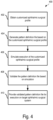
- FIG. 4 is a flow diagram showing an example process 400 of validating a customized ophthalmic surgical profile.
- Operations in the example process 400 may be performed by a data processing apparatus (e.g., the processor 112 of the example pattern validation system 108 of FIG. 1 ).
- Operations in the example process 400 may be performed by one or more multiple computer devices.
- one or more operations of the process 400 may be performed by a pattern design computer system (e.g., implemented similar to the pattern design systems 104 of FIG. 1 ), and other operations of the process 400 may be performed by a pattern validation computer system (e.g., implemented similar to the pattern validation system 108 of FIG. 1 ).
- the example process 400 may include additional or different operations, and the operations may be performed in the order shown or in another order.
- one or more of the operations shown in FIG. 4 are implemented as processes that include multiple operations, sub-processes, or other types of routines. In some cases, operations can be combined, performed in another order, performed in parallel, iterated, or otherwise repeated or performed another manner.
- the customized ophthalmic surgical profile may include an ophthalmic surgical pattern and one or more parameters associated with the ophthalmic surgical pattern.
- the ophthalmic surgical pattern may include a lens fragmentation pattern, a corneal incision pattern, a capsulotomy incision pattern, another type of ophthalmic surgical pattern, or a combination thereof.
- the parameters associated with the ophthalmic surgical pattern can include, for example, laser energy levels at various incision points within an eye (e.g., within a lens), geometric or freeform shapes defining incision lines, a distance between incision lines in the ophthalmic surgical pattern (e.g., radii of concentric circle incision lines as shown in FIG.
- the pattern validation system 108 may obtain a customized ophthalmic surgical profile intended to be executed on one or more of the target surgical systems 102.
- the customized ophthalmic surgical profile may be generated by a pattern design system 104 using a computer program implemented thereon.
- the customized ophthalmic surgical profile may be generated using one or more of the engines in the pattern design and validation tool 210, as described above.
- the customized ophthalmic surgical profile may include a validation and license verification request that requests verification of execution of the customized ophthalmic surgical profile and authentication of an operator providing the customized ophthalmic surgical profile, as described further below.
- a pattern definition file is generated.
- the pattern definition file may be generated in a format that is executable by a laser-based ophthalmic surgical system or a computer or server supporting a pattern design and validation system 210.
- the pattern definition file may be generated by any suitable system based on the customized ophthalmic surgical profile obtained at 402. For example, referring to the system 100 of FIG. 1 , either a pattern design system 104 or the pattern validation system 108 may generate the pattern definition file based on a customized ophthalmic surgical profile developed by one of the pattern design systems 104.
- the pattern definition file may be agnostic as to the type or model of the target surgical system.
- the pattern definition file may be formatted in such a way that it may be directly or indirectly executed on multiple different models of ophthalmic surgical systems.
- the pattern definition file may be compiled into an executable file for execution by different models of ophthalmic surgical systems.
- execution of the customized ophthalmic surgical profile obtained at 402 is simulated.
- the simulation may be based on the pattern definition file generated at 404.
- the simulation models one or more surgical control elements in the laser-based ophthalmic surgical system during execution of the customized ophthalmic surgical profile.
- simulating the customized ophthalmic surgical profile includes calculating laser scan coordinates for the customized surgical pattern, laser pulse energy parameters for each of the scan coordinates, galvanometer positioning for each of the scan coordinates and sequences, and a procedure time.
- a plurality of x-y-z scan coordinates that correspond to the parameters in the pattern definition file may be generated based on the ophthalmic surgical pattern in the customized surgical profile, pulse energies for each of the x-y-z scan coordinates may be determined based on the parameters in the customized surgical profile.
- a layering pattern for the x-y-z scan coordinates may also be determined.
- the x-y-z scan coordinates may be executed by a simulation engine that simulates operation of the target laser-based ophthalmic surgical system. In some instances, the simulation engine may be implemented similar to the pattern simulation engine 213 of FIG. 2 .
- simulating execution of the customized ophthalmic surgical profile includes optimizing laser pulse parameters (e.g., pulse frequency, duration, energy), scanning patterns, and galvanometer mirror positioning for the laser scan coordinates based on a characteristic of the laser-based ophthalmic surgical system. For example, a duration or energy of laser pulses called for by the customized surgical profile may be modified based on the capabilities of the target laser-based ophthalmic surgical system on which the profile will be executed. As another example, laser pulse repetition rates and scan patterns may be modified based on the capabilities of the target laser-based ophthalmic surgical system. Other aspects of the execution may be simulated as well, such as an overall time that the surgical pattern will take to execute on the target surgical system.
- the pattern definition file is validated based on the simulation at 406.
- the validation process may include verification of each aspect of the simulated execution of the customized surgical profile.
- validation includes calculating a surgical volume, local and total energy, and procedure time of the simulated application of the customized surgical laser pattern, and determining whether the surgical volume, total energy, and procedure time comply with predetermined thresholds for the target surgical system.
- the validation process may verify that a surgical volume dictated by the pattern definition file does not exceed predetermined volume parameters, that a laser energy level does not exceed a predetermined total energy or damage threshold, that a laser energy level is appropriate for the surgical procedure (e.g., safe and effective for the intended procedure), or that a laser pulse repetition rate and scan pattern does not exceed limits of the target surgical system (imposed, e.g., by the surgical reach of galvanometer mirrors in the laser scanner).
- validating the pattern definition file includes modifying the pattern definition file to allow the file to be executed on the laser-based ophthalmic surgical system.
- the pattern definition file as generated prior to validation may not be in a format that is executable by a target surgical system.
- the pattern definition file may be modified such that is may be executable by a target surgical system.
- validation may be performed by a software engine that analyzes the simulated operation of the target laser-based ophthalmic surgical system based on the pattern definition file.
- the validation engine may be implemented similar to the pattern validation engine 214 of FIG. 2 .
- the validation process also includes an authentication process.
- the authentication process may include a credential verification, license verification, or other type of verification that ensures the target surgical system or operator thereof has permission (e.g., from a manufacturer of the target surgical system or software provider for the target surgical system) to execute the pattern definition file.
- the customized ophthalmic surgical profile may include a license verification request that includes credentials for an operator of the target surgical system (e.g., a username/password combination) or license credentials (e.g., identifying a type of license the operator owns), and the authentication process may compare the credentials with information in a database (e.g., operator license data) to determine whether the operator is authorized to execute the pattern definition file on target system.
- a database e.g., operator license data
- a message may be generated to the operator.
- the message may include an explanation of why the operator was not authorized.
- the message may also initiate a process by which the operator of the target surgical system can obtain a license (e.g., by submitting a single-use, multi-use, or subscription license fee).
- a validated pattern definition file is provided for execution on a target ophthalmic surgical system.
- the pattern validation system 108 may provide a validated version of a pattern definition file directly to a target surgical system 102, or to a pattern design system 104 that loads the pattern definition file on the target surgical system 102 for execution.
- an error message or other notification may be sent.
- the pattern validation system 108 may generate and send a message indicating the validation failure to the pattern design system 104 that uploaded the pattern definition file for validation.
- the pattern definition file may be stored in a pattern repository.
- the pattern validation system 108 may validate a pattern definition file, provide the validated pattern definition file to one or more of the pattern design systems 104 or target surgical systems 102, and then store the validated pattern definition file in the pattern repository 110 so that the pattern may be accessed at a later time (e.g., for further modification, or for another execution by another target surgical system).
- Some of the subject matter and operations described in this specification can be implemented in digital electronic circuitry, or in computer software, firmware, or hardware, including the structures disclosed in this specification and their structural equivalents, or in combinations of one or more of them.
- Some of the subject matter described in this specification can be implemented as one or more computer programs, i.e., one or more modules of computer program instructions, encoded on a computer-readable storage medium for execution by, or to control the operation of, data-processing apparatus.
- a computer-readable storage medium can be, or can be included in, a computer-readable storage device, a computer-readable storage substrate, a random or serial access memory array or device, or a combination of one or more of them.
- a computer-readable storage medium is not a propagated signal
- a computer-readable storage medium can be a source or destination of computer program instructions encoded in an artificially generated propagated signal.
- the computer-readable storage medium can also be, or be included in, one or more separate physical components or media (e.g., multiple CDs, disks, or other storage devices).
- data processing apparatus encompasses all kinds of apparatus, devices, and machines for processing data, including by way of example a programmable processor, a computer, a system on a chip, or multiple ones, or combinations, of the foregoing.
- the apparatus can include special purpose logic circuitry, e.g., an FPGA (field programmable gate array) or an ASIC (application specific integrated circuit).
- the apparatus can also include, in addition to hardware, code that creates an execution environment for the computer program in question, e.g., code that constitutes processor firmware, a protocol stack, a database management system, an operating system, a cross-platform runtime environment, a virtual machine, or a combination of one or more of them.
- code that creates an execution environment for the computer program in question e.g., code that constitutes processor firmware, a protocol stack, a database management system, an operating system, a cross-platform runtime environment, a virtual machine, or a combination of one or more of them.
- a computer system may include a single computing device, or multiple computers that operate in proximity or generally remote from each other and typically interact through a communication network.
- Examples of communication networks include a local area network ("LAN”) and a wide area network (“WAN”), an inter-network (e.g., the Internet), a network comprising a satellite link, and peer-to-peer networks (e.g., ad hoc peer-to-peer networks).
- the computer system may include one or more data processing apparatuses coupled to computer-readable media storing one or more computer programs that may be executed by the one or more data processing apparatuses, and one or more interfaces for communicating with other computer systems.
- a computer program (also known as a program, software, software application, script, or code) can be written in any form of programming language, including compiled or interpreted languages, declarative or procedural languages, and it can be deployed in any form, including as a stand-alone program or as a module, component, subroutine, object, or other unit suitable for use in a computing environment.
- a computer program may, but need not, correspond to a file in a file system.
- a program can be stored in a portion of a file that holds other programs or data (e.g., one or more scripts stored in a markup language document), in a single file dedicated to the program, or in multiple coordinated files (e.g., files that store one or more modules, sub programs, or portions of code).
- a computer program can be deployed to be executed on one computer or on multiple computers that are located at one site or distributed across multiple sites and interconnected by a communication network.
- Embodiments of the present disclosure provide methods and systems for creating, validating, and re-using customized surgical profiles which may overcome limitations of conventional systems and methods. It will be appreciated that above-disclosed and other features and functions, or alternatives thereof, may be desirably combined into many other different systems or applications in accordance with the disclosure. It will also be appreciated that various presently unforeseen or unanticipated alternatives, modifications, variations, or improvements therein may be subsequently made by those skilled in the art which alternatives, variations and improvements are also intended to be encompassed by the following claims.
Landscapes
- Health & Medical Sciences (AREA)
- Engineering & Computer Science (AREA)
- Ophthalmology & Optometry (AREA)
- Public Health (AREA)
- Life Sciences & Earth Sciences (AREA)
- General Health & Medical Sciences (AREA)
- Surgery (AREA)
- Biomedical Technology (AREA)
- Veterinary Medicine (AREA)
- Heart & Thoracic Surgery (AREA)
- Animal Behavior & Ethology (AREA)
- Nuclear Medicine, Radiotherapy & Molecular Imaging (AREA)
- Physics & Mathematics (AREA)
- Vascular Medicine (AREA)
- Optics & Photonics (AREA)
- Medical Informatics (AREA)
- Software Systems (AREA)
- Theoretical Computer Science (AREA)
- Databases & Information Systems (AREA)
- Data Mining & Analysis (AREA)
- Pathology (AREA)
- Epidemiology (AREA)
- Primary Health Care (AREA)
- Robotics (AREA)
- Molecular Biology (AREA)
- General Engineering & Computer Science (AREA)
- General Physics & Mathematics (AREA)
- Laser Surgery Devices (AREA)
Applications Claiming Priority (2)
| Application Number | Priority Date | Filing Date | Title |
|---|---|---|---|
| US201762573209P | 2017-10-17 | 2017-10-17 | |
| PCT/IB2018/057740 WO2019077434A1 (en) | 2017-10-17 | 2018-10-04 | CUSTOM OPHTHALMIC SURGICAL PROFILES |
Publications (2)
| Publication Number | Publication Date |
|---|---|
| EP3697356A1 EP3697356A1 (en) | 2020-08-26 |
| EP3697356B1 true EP3697356B1 (en) | 2023-02-15 |
Family
ID=63840892
Family Applications (1)
| Application Number | Title | Priority Date | Filing Date |
|---|---|---|---|
| EP18786051.5A Active EP3697356B1 (en) | 2017-10-17 | 2018-10-04 | Customized ophthalmic surgical profiles |
Country Status (8)
| Country | Link |
|---|---|
| US (1) | US11127504B2 (zh) |
| EP (1) | EP3697356B1 (zh) |
| JP (1) | JP7385558B2 (zh) |
| CN (1) | CN111225639B (zh) |
| AU (1) | AU2018352182B2 (zh) |
| CA (1) | CA3073009A1 (zh) |
| ES (1) | ES2941994T3 (zh) |
| WO (1) | WO2019077434A1 (zh) |
Families Citing this family (106)
| Publication number | Priority date | Publication date | Assignee | Title |
|---|---|---|---|---|
| US11871901B2 (en) | 2012-05-20 | 2024-01-16 | Cilag Gmbh International | Method for situational awareness for surgical network or surgical network connected device capable of adjusting function based on a sensed situation or usage |
| US11504192B2 (en) | 2014-10-30 | 2022-11-22 | Cilag Gmbh International | Method of hub communication with surgical instrument systems |
| US11510741B2 (en) | 2017-10-30 | 2022-11-29 | Cilag Gmbh International | Method for producing a surgical instrument comprising a smart electrical system |
| US11311342B2 (en) | 2017-10-30 | 2022-04-26 | Cilag Gmbh International | Method for communicating with surgical instrument systems |
| US11229436B2 (en) | 2017-10-30 | 2022-01-25 | Cilag Gmbh International | Surgical system comprising a surgical tool and a surgical hub |
| US11759224B2 (en) | 2017-10-30 | 2023-09-19 | Cilag Gmbh International | Surgical instrument systems comprising handle arrangements |
| US11564756B2 (en) | 2017-10-30 | 2023-01-31 | Cilag Gmbh International | Method of hub communication with surgical instrument systems |
| US11317919B2 (en) | 2017-10-30 | 2022-05-03 | Cilag Gmbh International | Clip applier comprising a clip crimping system |
| US11801098B2 (en) | 2017-10-30 | 2023-10-31 | Cilag Gmbh International | Method of hub communication with surgical instrument systems |
| US11291510B2 (en) | 2017-10-30 | 2022-04-05 | Cilag Gmbh International | Method of hub communication with surgical instrument systems |
| US11911045B2 (en) | 2017-10-30 | 2024-02-27 | Cllag GmbH International | Method for operating a powered articulating multi-clip applier |
| US11413042B2 (en) | 2017-10-30 | 2022-08-16 | Cilag Gmbh International | Clip applier comprising a reciprocating clip advancing member |
| US11896443B2 (en) | 2017-12-28 | 2024-02-13 | Cilag Gmbh International | Control of a surgical system through a surgical barrier |
| US11576677B2 (en) | 2017-12-28 | 2023-02-14 | Cilag Gmbh International | Method of hub communication, processing, display, and cloud analytics |
| US11589888B2 (en) | 2017-12-28 | 2023-02-28 | Cilag Gmbh International | Method for controlling smart energy devices |
| US11786245B2 (en) | 2017-12-28 | 2023-10-17 | Cilag Gmbh International | Surgical systems with prioritized data transmission capabilities |
| US11998193B2 (en) | 2017-12-28 | 2024-06-04 | Cilag Gmbh International | Method for usage of the shroud as an aspect of sensing or controlling a powered surgical device, and a control algorithm to adjust its default operation |
| US11559308B2 (en) | 2017-12-28 | 2023-01-24 | Cilag Gmbh International | Method for smart energy device infrastructure |
| US11324557B2 (en) | 2017-12-28 | 2022-05-10 | Cilag Gmbh International | Surgical instrument with a sensing array |
| US11132462B2 (en) | 2017-12-28 | 2021-09-28 | Cilag Gmbh International | Data stripping method to interrogate patient records and create anonymized record |
| US11529187B2 (en) | 2017-12-28 | 2022-12-20 | Cilag Gmbh International | Surgical evacuation sensor arrangements |
| US11464535B2 (en) | 2017-12-28 | 2022-10-11 | Cilag Gmbh International | Detection of end effector emersion in liquid |
| US11166772B2 (en) | 2017-12-28 | 2021-11-09 | Cilag Gmbh International | Surgical hub coordination of control and communication of operating room devices |
| US11284936B2 (en) | 2017-12-28 | 2022-03-29 | Cilag Gmbh International | Surgical instrument having a flexible electrode |
| US11818052B2 (en) | 2017-12-28 | 2023-11-14 | Cilag Gmbh International | Surgical network determination of prioritization of communication, interaction, or processing based on system or device needs |
| US11896322B2 (en) | 2017-12-28 | 2024-02-13 | Cilag Gmbh International | Sensing the patient position and contact utilizing the mono-polar return pad electrode to provide situational awareness to the hub |
| US11311306B2 (en) | 2017-12-28 | 2022-04-26 | Cilag Gmbh International | Surgical systems for detecting end effector tissue distribution irregularities |
| US11291495B2 (en) | 2017-12-28 | 2022-04-05 | Cilag Gmbh International | Interruption of energy due to inadvertent capacitive coupling |
| US11410259B2 (en) | 2017-12-28 | 2022-08-09 | Cilag Gmbh International | Adaptive control program updates for surgical devices |
| US11304699B2 (en) * | 2017-12-28 | 2022-04-19 | Cilag Gmbh International | Method for adaptive control schemes for surgical network control and interaction |
| US11234756B2 (en) | 2017-12-28 | 2022-02-01 | Cilag Gmbh International | Powered surgical tool with predefined adjustable control algorithm for controlling end effector parameter |
| US11937769B2 (en) | 2017-12-28 | 2024-03-26 | Cilag Gmbh International | Method of hub communication, processing, storage and display |
| US11540855B2 (en) | 2017-12-28 | 2023-01-03 | Cilag Gmbh International | Controlling activation of an ultrasonic surgical instrument according to the presence of tissue |
| US11257589B2 (en) | 2017-12-28 | 2022-02-22 | Cilag Gmbh International | Real-time analysis of comprehensive cost of all instrumentation used in surgery utilizing data fluidity to track instruments through stocking and in-house processes |
| US11304720B2 (en) | 2017-12-28 | 2022-04-19 | Cilag Gmbh International | Activation of energy devices |
| US11832840B2 (en) | 2017-12-28 | 2023-12-05 | Cilag Gmbh International | Surgical instrument having a flexible circuit |
| US11844579B2 (en) | 2017-12-28 | 2023-12-19 | Cilag Gmbh International | Adjustments based on airborne particle properties |
| US11179175B2 (en) | 2017-12-28 | 2021-11-23 | Cilag Gmbh International | Controlling an ultrasonic surgical instrument according to tissue location |
| US11571234B2 (en) | 2017-12-28 | 2023-02-07 | Cilag Gmbh International | Temperature control of ultrasonic end effector and control system therefor |
| US11109866B2 (en) | 2017-12-28 | 2021-09-07 | Cilag Gmbh International | Method for circular stapler control algorithm adjustment based on situational awareness |
| US11864728B2 (en) | 2017-12-28 | 2024-01-09 | Cilag Gmbh International | Characterization of tissue irregularities through the use of mono-chromatic light refractivity |
| US11304763B2 (en) | 2017-12-28 | 2022-04-19 | Cilag Gmbh International | Image capturing of the areas outside the abdomen to improve placement and control of a surgical device in use |
| US11424027B2 (en) | 2017-12-28 | 2022-08-23 | Cilag Gmbh International | Method for operating surgical instrument systems |
| US11179208B2 (en) | 2017-12-28 | 2021-11-23 | Cilag Gmbh International | Cloud-based medical analytics for security and authentication trends and reactive measures |
| US11672605B2 (en) | 2017-12-28 | 2023-06-13 | Cilag Gmbh International | Sterile field interactive control displays |
| US11559307B2 (en) | 2017-12-28 | 2023-01-24 | Cilag Gmbh International | Method of robotic hub communication, detection, and control |
| US10892995B2 (en) | 2017-12-28 | 2021-01-12 | Ethicon Llc | Surgical network determination of prioritization of communication, interaction, or processing based on system or device needs |
| US11446052B2 (en) | 2017-12-28 | 2022-09-20 | Cilag Gmbh International | Variation of radio frequency and ultrasonic power level in cooperation with varying clamp arm pressure to achieve predefined heat flux or power applied to tissue |
| US11602393B2 (en) | 2017-12-28 | 2023-03-14 | Cilag Gmbh International | Surgical evacuation sensing and generator control |
| US11696760B2 (en) | 2017-12-28 | 2023-07-11 | Cilag Gmbh International | Safety systems for smart powered surgical stapling |
| US11376002B2 (en) | 2017-12-28 | 2022-07-05 | Cilag Gmbh International | Surgical instrument cartridge sensor assemblies |
| US11666331B2 (en) | 2017-12-28 | 2023-06-06 | Cilag Gmbh International | Systems for detecting proximity of surgical end effector to cancerous tissue |
| US11202570B2 (en) | 2017-12-28 | 2021-12-21 | Cilag Gmbh International | Communication hub and storage device for storing parameters and status of a surgical device to be shared with cloud based analytics systems |
| US11832899B2 (en) | 2017-12-28 | 2023-12-05 | Cilag Gmbh International | Surgical systems with autonomously adjustable control programs |
| US12035890B2 (en) | 2017-12-28 | 2024-07-16 | Cilag Gmbh International | Method of sensing particulate from smoke evacuated from a patient, adjusting the pump speed based on the sensed information, and communicating the functional parameters of the system to the hub |
| US11771487B2 (en) | 2017-12-28 | 2023-10-03 | Cilag Gmbh International | Mechanisms for controlling different electromechanical systems of an electrosurgical instrument |
| US20190201139A1 (en) | 2017-12-28 | 2019-07-04 | Ethicon Llc | Communication arrangements for robot-assisted surgical platforms |
| US11389164B2 (en) | 2017-12-28 | 2022-07-19 | Cilag Gmbh International | Method of using reinforced flexible circuits with multiple sensors to optimize performance of radio frequency devices |
| US11317937B2 (en) | 2018-03-08 | 2022-05-03 | Cilag Gmbh International | Determining the state of an ultrasonic end effector |
| US11786251B2 (en) | 2017-12-28 | 2023-10-17 | Cilag Gmbh International | Method for adaptive control schemes for surgical network control and interaction |
| US11857152B2 (en) | 2017-12-28 | 2024-01-02 | Cilag Gmbh International | Surgical hub spatial awareness to determine devices in operating theater |
| US11659023B2 (en) | 2017-12-28 | 2023-05-23 | Cilag Gmbh International | Method of hub communication |
| US11903601B2 (en) | 2017-12-28 | 2024-02-20 | Cilag Gmbh International | Surgical instrument comprising a plurality of drive systems |
| US11423007B2 (en) | 2017-12-28 | 2022-08-23 | Cilag Gmbh International | Adjustment of device control programs based on stratified contextual data in addition to the data |
| US11160605B2 (en) | 2017-12-28 | 2021-11-02 | Cilag Gmbh International | Surgical evacuation sensing and motor control |
| US11266468B2 (en) | 2017-12-28 | 2022-03-08 | Cilag Gmbh International | Cooperative utilization of data derived from secondary sources by intelligent surgical hubs |
| US11308075B2 (en) | 2017-12-28 | 2022-04-19 | Cilag Gmbh International | Surgical network, instrument, and cloud responses based on validation of received dataset and authentication of its source and integrity |
| US11304745B2 (en) | 2017-12-28 | 2022-04-19 | Cilag Gmbh International | Surgical evacuation sensing and display |
| US11419630B2 (en) | 2017-12-28 | 2022-08-23 | Cilag Gmbh International | Surgical system distributed processing |
| US11364075B2 (en) | 2017-12-28 | 2022-06-21 | Cilag Gmbh International | Radio frequency energy device for delivering combined electrical signals |
| US11744604B2 (en) | 2017-12-28 | 2023-09-05 | Cilag Gmbh International | Surgical instrument with a hardware-only control circuit |
| US11464559B2 (en) | 2017-12-28 | 2022-10-11 | Cilag Gmbh International | Estimating state of ultrasonic end effector and control system therefor |
| US11419667B2 (en) | 2017-12-28 | 2022-08-23 | Cilag Gmbh International | Ultrasonic energy device which varies pressure applied by clamp arm to provide threshold control pressure at a cut progression location |
| US11633237B2 (en) | 2017-12-28 | 2023-04-25 | Cilag Gmbh International | Usage and technique analysis of surgeon / staff performance against a baseline to optimize device utilization and performance for both current and future procedures |
| US11273001B2 (en) | 2017-12-28 | 2022-03-15 | Cilag Gmbh International | Surgical hub and modular device response adjustment based on situational awareness |
| US12062442B2 (en) | 2017-12-28 | 2024-08-13 | Cilag Gmbh International | Method for operating surgical instrument systems |
| US11278281B2 (en) | 2017-12-28 | 2022-03-22 | Cilag Gmbh International | Interactive surgical system |
| US11253315B2 (en) | 2017-12-28 | 2022-02-22 | Cilag Gmbh International | Increasing radio frequency to create pad-less monopolar loop |
| US11678881B2 (en) | 2017-12-28 | 2023-06-20 | Cilag Gmbh International | Spatial awareness of surgical hubs in operating rooms |
| US20190206569A1 (en) | 2017-12-28 | 2019-07-04 | Ethicon Llc | Method of cloud based data analytics for use with the hub |
| US11969216B2 (en) | 2017-12-28 | 2024-04-30 | Cilag Gmbh International | Surgical network recommendations from real time analysis of procedure variables against a baseline highlighting differences from the optimal solution |
| US11969142B2 (en) | 2017-12-28 | 2024-04-30 | Cilag Gmbh International | Method of compressing tissue within a stapling device and simultaneously displaying the location of the tissue within the jaws |
| US11213359B2 (en) | 2017-12-28 | 2022-01-04 | Cilag Gmbh International | Controllers for robot-assisted surgical platforms |
| US11076921B2 (en) | 2017-12-28 | 2021-08-03 | Cilag Gmbh International | Adaptive control program updates for surgical hubs |
| US10758310B2 (en) | 2017-12-28 | 2020-09-01 | Ethicon Llc | Wireless pairing of a surgical device with another device within a sterile surgical field based on the usage and situational awareness of devices |
| US11432885B2 (en) | 2017-12-28 | 2022-09-06 | Cilag Gmbh International | Sensing arrangements for robot-assisted surgical platforms |
| US11259830B2 (en) | 2018-03-08 | 2022-03-01 | Cilag Gmbh International | Methods for controlling temperature in ultrasonic device |
| US11701162B2 (en) | 2018-03-08 | 2023-07-18 | Cilag Gmbh International | Smart blade application for reusable and disposable devices |
| US11389188B2 (en) | 2018-03-08 | 2022-07-19 | Cilag Gmbh International | Start temperature of blade |
| US11278280B2 (en) | 2018-03-28 | 2022-03-22 | Cilag Gmbh International | Surgical instrument comprising a jaw closure lockout |
| US11259806B2 (en) | 2018-03-28 | 2022-03-01 | Cilag Gmbh International | Surgical stapling devices with features for blocking advancement of a camming assembly of an incompatible cartridge installed therein |
| US11471156B2 (en) | 2018-03-28 | 2022-10-18 | Cilag Gmbh International | Surgical stapling devices with improved rotary driven closure systems |
| US11090047B2 (en) | 2018-03-28 | 2021-08-17 | Cilag Gmbh International | Surgical instrument comprising an adaptive control system |
| US11406382B2 (en) | 2018-03-28 | 2022-08-09 | Cilag Gmbh International | Staple cartridge comprising a lockout key configured to lift a firing member |
| US11219453B2 (en) | 2018-03-28 | 2022-01-11 | Cilag Gmbh International | Surgical stapling devices with cartridge compatible closure and firing lockout arrangements |
| US11207067B2 (en) | 2018-03-28 | 2021-12-28 | Cilag Gmbh International | Surgical stapling device with separate rotary driven closure and firing systems and firing member that engages both jaws while firing |
| US11291445B2 (en) | 2019-02-19 | 2022-04-05 | Cilag Gmbh International | Surgical staple cartridges with integral authentication keys |
| US11751872B2 (en) | 2019-02-19 | 2023-09-12 | Cilag Gmbh International | Insertable deactivator element for surgical stapler lockouts |
| US11317915B2 (en) | 2019-02-19 | 2022-05-03 | Cilag Gmbh International | Universal cartridge based key feature that unlocks multiple lockout arrangements in different surgical staplers |
| US11369377B2 (en) | 2019-02-19 | 2022-06-28 | Cilag Gmbh International | Surgical stapling assembly with cartridge based retainer configured to unlock a firing lockout |
| US11357503B2 (en) | 2019-02-19 | 2022-06-14 | Cilag Gmbh International | Staple cartridge retainers with frangible retention features and methods of using same |
| EP3744285A1 (en) * | 2019-05-27 | 2020-12-02 | Leica Instruments (Singapore) Pte. Ltd. | Microscope system and method for controlling a surgical microcope |
| USD950728S1 (en) | 2019-06-25 | 2022-05-03 | Cilag Gmbh International | Surgical staple cartridge |
| USD952144S1 (en) | 2019-06-25 | 2022-05-17 | Cilag Gmbh International | Surgical staple cartridge retainer with firing system authentication key |
| USD964564S1 (en) | 2019-06-25 | 2022-09-20 | Cilag Gmbh International | Surgical staple cartridge retainer with a closure system authentication key |
| CN114153313B (zh) * | 2021-11-29 | 2022-10-04 | 苏州密尔光子科技有限公司 | 激光手术器械控制方法、装置及电子设备 |
Family Cites Families (29)
| Publication number | Priority date | Publication date | Assignee | Title |
|---|---|---|---|---|
| US6099522A (en) | 1989-02-06 | 2000-08-08 | Visx Inc. | Automated laser workstation for high precision surgical and industrial interventions |
| US6325792B1 (en) * | 1991-11-06 | 2001-12-04 | Casimir A. Swinger | Ophthalmic surgical laser and method |
| US5984916A (en) * | 1993-04-20 | 1999-11-16 | Lai; Shui T. | Ophthalmic surgical laser and method |
| EP1516156B1 (en) * | 2002-05-30 | 2019-10-23 | AMO Manufacturing USA, LLC | Tracking torsional eye orientation and position |
| US6814729B2 (en) | 2002-06-27 | 2004-11-09 | Technovision Gmbh | Laser vision correction apparatus and control method |
| US9456925B2 (en) * | 2007-09-06 | 2016-10-04 | Alcon Lensx, Inc. | Photodisruptive laser treatment of the crystalline lens |
| US20100324543A1 (en) * | 2007-09-18 | 2010-12-23 | Kurtz Ronald M | Method And Apparatus For Integrating Cataract Surgery With Glaucoma Or Astigmatism Surgery |
| PT3363415T (pt) | 2008-01-09 | 2019-11-05 | Alcon Lensx Inc | Fragmentação curva de tecido por laser fotodisruptivo |
| EP2271250B1 (en) * | 2008-04-22 | 2021-09-01 | AMO Development LLC | High-order optical correction during corneal laser surgery |
| US8005947B2 (en) * | 2008-09-22 | 2011-08-23 | Abbott Medical Optics Inc. | Systems and methods for providing remote diagnostics and support for surgical systems |
| DE102008053827A1 (de) * | 2008-10-30 | 2010-05-12 | Technolas Perfect Vision Gmbh | Vorrichtung und Verfahren zum Bereitstellen einer Laserschussdatei |
| EP2236109B1 (de) * | 2009-04-02 | 2014-10-22 | SIE AG, Surgical Instrument Engineering | System zum Definieren von Schnitten in Augengewebe |
| US9411938B2 (en) | 2009-04-02 | 2016-08-09 | Sie Ag, Surgical Instrument Engineering | System for defining cuts in eye tissue |
| US20100256964A1 (en) | 2009-04-07 | 2010-10-07 | Schlumberger Technology Corporation | System and technique to quantify a fracture system |
| CN103892959B (zh) * | 2009-05-26 | 2016-04-06 | 视乐有限公司 | 用于眼科激光手术的系统 |
| US9492322B2 (en) * | 2009-11-16 | 2016-11-15 | Alcon Lensx, Inc. | Imaging surgical target tissue by nonlinear scanning |
| WO2012135073A2 (en) * | 2011-03-25 | 2012-10-04 | Board Of Trustees Of Michigan State University | Adaptive laser system for ophthalmic use |
| US9622913B2 (en) * | 2011-05-18 | 2017-04-18 | Alcon Lensx, Inc. | Imaging-controlled laser surgical system |
| US9066784B2 (en) * | 2011-12-19 | 2015-06-30 | Alcon Lensx, Inc. | Intra-surgical optical coherence tomographic imaging of cataract procedures |
| US10182943B2 (en) * | 2012-03-09 | 2019-01-22 | Alcon Lensx, Inc. | Adjustable pupil system for surgical laser systems |
| KR101444757B1 (ko) * | 2013-02-19 | 2014-09-30 | 주식회사 루트로닉 | 안과용 수술장치 |
| JP6434015B2 (ja) * | 2013-07-25 | 2018-12-05 | オプティメディカ コーポレイション | 物体の屈折率のインサイチュー算定 |
| CA2916058A1 (en) * | 2013-11-07 | 2015-05-14 | Amo Development Llc | Treatment validation systems and methods |
| ES2749380T3 (es) * | 2014-02-28 | 2020-03-20 | Excel Lens Inc | Cirugía de cataratas asistida por láser |
| US9814619B2 (en) * | 2014-09-18 | 2017-11-14 | Excelsius Medical, Inc. | Ophthalmological laser method |
| WO2016061511A1 (en) * | 2014-10-17 | 2016-04-21 | Optimedica Corporation | Laser eye surgery lens fragmentation |
| US9770362B2 (en) * | 2014-12-23 | 2017-09-26 | Novartis Ag | Wavefront correction for ophthalmic surgical lasers |
| CN107920919B (zh) * | 2015-03-18 | 2020-10-27 | 光学医疗公司 | 激光眼科手术期间的真空损失检测 |
| US10485705B2 (en) * | 2015-07-01 | 2019-11-26 | Optimedica Corporation | Sub-nanosecond laser cataract surgery system |
-
2018
- 2018-10-04 JP JP2020516706A patent/JP7385558B2/ja active Active
- 2018-10-04 US US16/152,313 patent/US11127504B2/en active Active
- 2018-10-04 AU AU2018352182A patent/AU2018352182B2/en active Active
- 2018-10-04 EP EP18786051.5A patent/EP3697356B1/en active Active
- 2018-10-04 ES ES18786051T patent/ES2941994T3/es active Active
- 2018-10-04 CA CA3073009A patent/CA3073009A1/en active Pending
- 2018-10-04 CN CN201880067755.XA patent/CN111225639B/zh active Active
- 2018-10-04 WO PCT/IB2018/057740 patent/WO2019077434A1/en unknown
Also Published As
| Publication number | Publication date |
|---|---|
| EP3697356A1 (en) | 2020-08-26 |
| AU2018352182A1 (en) | 2020-03-05 |
| AU2018352182B2 (en) | 2024-06-06 |
| JP2020537554A (ja) | 2020-12-24 |
| US20190115108A1 (en) | 2019-04-18 |
| US11127504B2 (en) | 2021-09-21 |
| JP7385558B2 (ja) | 2023-11-22 |
| CN111225639B (zh) | 2022-10-18 |
| CA3073009A1 (en) | 2019-04-25 |
| WO2019077434A1 (en) | 2019-04-25 |
| ES2941994T3 (es) | 2023-05-29 |
| CN111225639A (zh) | 2020-06-02 |
Similar Documents
| Publication | Publication Date | Title |
|---|---|---|
| EP3697356B1 (en) | Customized ophthalmic surgical profiles | |
| US9411938B2 (en) | System for defining cuts in eye tissue | |
| JP6602299B2 (ja) | 効率的治療計画トレードオフ分析 | |
| US12076912B2 (en) | Systems and methods of cellular-hull infill structure generation for additive manufacturing | |
| JP2013502965A (ja) | 放射線治療計画に使用される補償器のための対話型のコンピュータを利用したエディタ | |
| US20180079138A1 (en) | Three-dimensional object-manufacturing apparatus, three-dimensional object-manufacturing method, and program | |
| EP3340100A1 (en) | Additive manufacturing system and method for validating additively manufactured components | |
| EP3232351B1 (en) | System and process for evaluating and validating additive manufacturing operations | |
| US20210325849A1 (en) | Transfer learning/dictionary generation and usage for tailored part parameter generation from coupon builds | |
| WO2012135196A1 (en) | Defining the volumetric dimensions and surface of a compensator | |
| Mann et al. | Development and clinical implementation of eclipse scripting‐based automated patient‐specific collision avoidance software | |
| JP6823299B2 (ja) | 放射線治療計画装置および放射線治療システム | |
| EP3232352A1 (en) | System and process for evaluating and validating additive manufacturing operations | |
| JP2023548950A (ja) | 放射線治療計画のための線量マップを予測する方法及びコンピュータプログラム | |
| CN115697482A (zh) | 放射疗法治疗中使用的静态设备和用于该设备的设计方法 | |
| KR102412652B1 (ko) | 인공지능 학습용 데이터 생성 시스템 | |
| JP2014102243A (ja) | 形状測定装置、構造物製造システム、形状測定方法、構造物製造方法、及びそのプログラム | |
| US20230277871A1 (en) | Method and planning device for planning a locally selective irradiation of a working area, computer program, method and manufacturing device for additively manufacturing an object from a powder material | |
| JP4079544B2 (ja) | 光造形法及びその装置 | |
| CN111712182B (zh) | 用于激光扫描系统的系统反相控制器 | |
| JP2018134208A (ja) | 放射線治療計画装置 | |
| CN118203470A (zh) | 用于为治疗设备的激光器提供变形校正控制数据的方法 | |
| WO2024072455A1 (en) | Additive manufacturing using a build process with lazy local slicing | |
| CN118265555A (zh) | 用于生成虚拟组织等效物属性的机器学习建模 |
Legal Events
| Date | Code | Title | Description |
|---|---|---|---|
| STAA | Information on the status of an ep patent application or granted ep patent |
Free format text: STATUS: UNKNOWN |
|
| STAA | Information on the status of an ep patent application or granted ep patent |
Free format text: STATUS: THE INTERNATIONAL PUBLICATION HAS BEEN MADE |
|
| PUAI | Public reference made under article 153(3) epc to a published international application that has entered the european phase |
Free format text: ORIGINAL CODE: 0009012 |
|
| STAA | Information on the status of an ep patent application or granted ep patent |
Free format text: STATUS: REQUEST FOR EXAMINATION WAS MADE |
|
| 17P | Request for examination filed |
Effective date: 20200429 |
|
| AK | Designated contracting states |
Kind code of ref document: A1 Designated state(s): AL AT BE BG CH CY CZ DE DK EE ES FI FR GB GR HR HU IE IS IT LI LT LU LV MC MK MT NL NO PL PT RO RS SE SI SK SM TR |
|
| AX | Request for extension of the european patent |
Extension state: BA ME |
|
| DAV | Request for validation of the european patent (deleted) | ||
| DAX | Request for extension of the european patent (deleted) | ||
| GRAP | Despatch of communication of intention to grant a patent |
Free format text: ORIGINAL CODE: EPIDOSNIGR1 |
|
| STAA | Information on the status of an ep patent application or granted ep patent |
Free format text: STATUS: GRANT OF PATENT IS INTENDED |
|
| INTG | Intention to grant announced |
Effective date: 20220920 |
|
| RIN1 | Information on inventor provided before grant (corrected) |
Inventor name: SRASS, HADI Inventor name: HEGEDUS, IMRE |
|
| GRAS | Grant fee paid |
Free format text: ORIGINAL CODE: EPIDOSNIGR3 |
|
| GRAA | (expected) grant |
Free format text: ORIGINAL CODE: 0009210 |
|
| STAA | Information on the status of an ep patent application or granted ep patent |
Free format text: STATUS: THE PATENT HAS BEEN GRANTED |
|
| AK | Designated contracting states |
Kind code of ref document: B1 Designated state(s): AL AT BE BG CH CY CZ DE DK EE ES FI FR GB GR HR HU IE IS IT LI LT LU LV MC MK MT NL NO PL PT RO RS SE SI SK SM TR |
|
| REG | Reference to a national code |
Ref country code: CH Ref legal event code: EP Ref country code: GB Ref legal event code: FG4D |
|
| REG | Reference to a national code |
Ref country code: DE Ref legal event code: R096 Ref document number: 602018046182 Country of ref document: DE |
|
| REG | Reference to a national code |
Ref country code: AT Ref legal event code: REF Ref document number: 1547874 Country of ref document: AT Kind code of ref document: T Effective date: 20230315 Ref country code: IE Ref legal event code: FG4D |
|
| REG | Reference to a national code |
Ref country code: ES Ref legal event code: FG2A Ref document number: 2941994 Country of ref document: ES Kind code of ref document: T3 Effective date: 20230529 |
|
| REG | Reference to a national code |
Ref country code: LT Ref legal event code: MG9D |
|
| P01 | Opt-out of the competence of the unified patent court (upc) registered |
Effective date: 20230505 |
|
| REG | Reference to a national code |
Ref country code: NL Ref legal event code: MP Effective date: 20230215 |
|
| REG | Reference to a national code |
Ref country code: AT Ref legal event code: MK05 Ref document number: 1547874 Country of ref document: AT Kind code of ref document: T Effective date: 20230215 |
|
| PG25 | Lapsed in a contracting state [announced via postgrant information from national office to epo] |
Ref country code: RS Free format text: LAPSE BECAUSE OF FAILURE TO SUBMIT A TRANSLATION OF THE DESCRIPTION OR TO PAY THE FEE WITHIN THE PRESCRIBED TIME-LIMIT Effective date: 20230215 Ref country code: PT Free format text: LAPSE BECAUSE OF FAILURE TO SUBMIT A TRANSLATION OF THE DESCRIPTION OR TO PAY THE FEE WITHIN THE PRESCRIBED TIME-LIMIT Effective date: 20230615 Ref country code: NO Free format text: LAPSE BECAUSE OF FAILURE TO SUBMIT A TRANSLATION OF THE DESCRIPTION OR TO PAY THE FEE WITHIN THE PRESCRIBED TIME-LIMIT Effective date: 20230515 Ref country code: NL Free format text: LAPSE BECAUSE OF FAILURE TO SUBMIT A TRANSLATION OF THE DESCRIPTION OR TO PAY THE FEE WITHIN THE PRESCRIBED TIME-LIMIT Effective date: 20230215 Ref country code: LV Free format text: LAPSE BECAUSE OF FAILURE TO SUBMIT A TRANSLATION OF THE DESCRIPTION OR TO PAY THE FEE WITHIN THE PRESCRIBED TIME-LIMIT Effective date: 20230215 Ref country code: LT Free format text: LAPSE BECAUSE OF FAILURE TO SUBMIT A TRANSLATION OF THE DESCRIPTION OR TO PAY THE FEE WITHIN THE PRESCRIBED TIME-LIMIT Effective date: 20230215 Ref country code: HR Free format text: LAPSE BECAUSE OF FAILURE TO SUBMIT A TRANSLATION OF THE DESCRIPTION OR TO PAY THE FEE WITHIN THE PRESCRIBED TIME-LIMIT Effective date: 20230215 Ref country code: AT Free format text: LAPSE BECAUSE OF FAILURE TO SUBMIT A TRANSLATION OF THE DESCRIPTION OR TO PAY THE FEE WITHIN THE PRESCRIBED TIME-LIMIT Effective date: 20230215 |
|
| PG25 | Lapsed in a contracting state [announced via postgrant information from national office to epo] |
Ref country code: SE Free format text: LAPSE BECAUSE OF FAILURE TO SUBMIT A TRANSLATION OF THE DESCRIPTION OR TO PAY THE FEE WITHIN THE PRESCRIBED TIME-LIMIT Effective date: 20230215 Ref country code: PL Free format text: LAPSE BECAUSE OF FAILURE TO SUBMIT A TRANSLATION OF THE DESCRIPTION OR TO PAY THE FEE WITHIN THE PRESCRIBED TIME-LIMIT Effective date: 20230215 Ref country code: IS Free format text: LAPSE BECAUSE OF FAILURE TO SUBMIT A TRANSLATION OF THE DESCRIPTION OR TO PAY THE FEE WITHIN THE PRESCRIBED TIME-LIMIT Effective date: 20230615 Ref country code: GR Free format text: LAPSE BECAUSE OF FAILURE TO SUBMIT A TRANSLATION OF THE DESCRIPTION OR TO PAY THE FEE WITHIN THE PRESCRIBED TIME-LIMIT Effective date: 20230516 Ref country code: FI Free format text: LAPSE BECAUSE OF FAILURE TO SUBMIT A TRANSLATION OF THE DESCRIPTION OR TO PAY THE FEE WITHIN THE PRESCRIBED TIME-LIMIT Effective date: 20230215 |
|
| PG25 | Lapsed in a contracting state [announced via postgrant information from national office to epo] |
Ref country code: SM Free format text: LAPSE BECAUSE OF FAILURE TO SUBMIT A TRANSLATION OF THE DESCRIPTION OR TO PAY THE FEE WITHIN THE PRESCRIBED TIME-LIMIT Effective date: 20230215 Ref country code: RO Free format text: LAPSE BECAUSE OF FAILURE TO SUBMIT A TRANSLATION OF THE DESCRIPTION OR TO PAY THE FEE WITHIN THE PRESCRIBED TIME-LIMIT Effective date: 20230215 Ref country code: EE Free format text: LAPSE BECAUSE OF FAILURE TO SUBMIT A TRANSLATION OF THE DESCRIPTION OR TO PAY THE FEE WITHIN THE PRESCRIBED TIME-LIMIT Effective date: 20230215 Ref country code: DK Free format text: LAPSE BECAUSE OF FAILURE TO SUBMIT A TRANSLATION OF THE DESCRIPTION OR TO PAY THE FEE WITHIN THE PRESCRIBED TIME-LIMIT Effective date: 20230215 Ref country code: CZ Free format text: LAPSE BECAUSE OF FAILURE TO SUBMIT A TRANSLATION OF THE DESCRIPTION OR TO PAY THE FEE WITHIN THE PRESCRIBED TIME-LIMIT Effective date: 20230215 |
|
| PGFP | Annual fee paid to national office [announced via postgrant information from national office to epo] |
Ref country code: GB Payment date: 20230921 Year of fee payment: 6 |
|
| REG | Reference to a national code |
Ref country code: DE Ref legal event code: R097 Ref document number: 602018046182 Country of ref document: DE |
|
| PG25 | Lapsed in a contracting state [announced via postgrant information from national office to epo] |
Ref country code: SK Free format text: LAPSE BECAUSE OF FAILURE TO SUBMIT A TRANSLATION OF THE DESCRIPTION OR TO PAY THE FEE WITHIN THE PRESCRIBED TIME-LIMIT Effective date: 20230215 |
|
| PGFP | Annual fee paid to national office [announced via postgrant information from national office to epo] |
Ref country code: FR Payment date: 20230921 Year of fee payment: 6 |
|
| PLBE | No opposition filed within time limit |
Free format text: ORIGINAL CODE: 0009261 |
|
| STAA | Information on the status of an ep patent application or granted ep patent |
Free format text: STATUS: NO OPPOSITION FILED WITHIN TIME LIMIT |
|
| PGFP | Annual fee paid to national office [announced via postgrant information from national office to epo] |
Ref country code: ES Payment date: 20231106 Year of fee payment: 6 |
|
| 26N | No opposition filed |
Effective date: 20231116 |
|
| PG25 | Lapsed in a contracting state [announced via postgrant information from national office to epo] |
Ref country code: SI Free format text: LAPSE BECAUSE OF FAILURE TO SUBMIT A TRANSLATION OF THE DESCRIPTION OR TO PAY THE FEE WITHIN THE PRESCRIBED TIME-LIMIT Effective date: 20230215 |
|
| PGFP | Annual fee paid to national office [announced via postgrant information from national office to epo] |
Ref country code: IT Payment date: 20230926 Year of fee payment: 6 Ref country code: DE Payment date: 20230919 Year of fee payment: 6 |
|
| PG25 | Lapsed in a contracting state [announced via postgrant information from national office to epo] |
Ref country code: MC Free format text: LAPSE BECAUSE OF FAILURE TO SUBMIT A TRANSLATION OF THE DESCRIPTION OR TO PAY THE FEE WITHIN THE PRESCRIBED TIME-LIMIT Effective date: 20230215 |
|
| REG | Reference to a national code |
Ref country code: CH Ref legal event code: PL |
|
| REG | Reference to a national code |
Ref country code: BE Ref legal event code: MM Effective date: 20231031 |
|
| PG25 | Lapsed in a contracting state [announced via postgrant information from national office to epo] |
Ref country code: LU Free format text: LAPSE BECAUSE OF NON-PAYMENT OF DUE FEES Effective date: 20231004 |
|
| PG25 | Lapsed in a contracting state [announced via postgrant information from national office to epo] |
Ref country code: LU Free format text: LAPSE BECAUSE OF NON-PAYMENT OF DUE FEES Effective date: 20231004 |
|
| PG25 | Lapsed in a contracting state [announced via postgrant information from national office to epo] |
Ref country code: CH Free format text: LAPSE BECAUSE OF NON-PAYMENT OF DUE FEES Effective date: 20231031 |
|
| PG25 | Lapsed in a contracting state [announced via postgrant information from national office to epo] |
Ref country code: CH Free format text: LAPSE BECAUSE OF NON-PAYMENT OF DUE FEES Effective date: 20231031 |
|
| PG25 | Lapsed in a contracting state [announced via postgrant information from national office to epo] |
Ref country code: BE Free format text: LAPSE BECAUSE OF NON-PAYMENT OF DUE FEES Effective date: 20231031 |