EP3697187A1 - Method for roll bending of electrical pins of components - Google Patents
Method for roll bending of electrical pins of components Download PDFInfo
- Publication number
- EP3697187A1 EP3697187A1 EP20157059.5A EP20157059A EP3697187A1 EP 3697187 A1 EP3697187 A1 EP 3697187A1 EP 20157059 A EP20157059 A EP 20157059A EP 3697187 A1 EP3697187 A1 EP 3697187A1
- Authority
- EP
- European Patent Office
- Prior art keywords
- pins
- bending
- clamp
- base
- bending station
- Prior art date
- Legal status (The legal status is an assumption and is not a legal conclusion. Google has not performed a legal analysis and makes no representation as to the accuracy of the status listed.)
- Withdrawn
Links
Images


Classifications
-
- H—ELECTRICITY
- H05—ELECTRIC TECHNIQUES NOT OTHERWISE PROVIDED FOR
- H05K—PRINTED CIRCUITS; CASINGS OR CONSTRUCTIONAL DETAILS OF ELECTRIC APPARATUS; MANUFACTURE OF ASSEMBLAGES OF ELECTRICAL COMPONENTS
- H05K13/00—Apparatus or processes specially adapted for manufacturing or adjusting assemblages of electric components
- H05K13/02—Feeding of components
- H05K13/023—Feeding of components with bending or straightening of the terminal leads
- H05K13/024—Straightening or aligning terminal leads
- H05K13/026—Straightening or aligning terminal leads of components having terminal leads in side by side relationship, e.g. using combing elements
Definitions
- the present invention relates to a method of bending the electrical contact pins of components, as well as to a bending station implementing such a method.
- Motor vehicles include an increasing number of electronic systems, in particular for improving the control of combustion of heat engines or for controlling electric traction machines of hybrid or electric vehicles, in order to reduce energy consumption and emissions. polluting gases, to help driving, to automate it, or for many other functions to improve comfort and safety.
- hall effect sensors are used in mechatronic systems, to measure or control movements or positions.
- These components can be mass produced with pins arranged in the same plane, forming a manufacturing standard. It is then necessary, depending on the applications, to make a specific bending and cutting of the ends of the pins, in order to obtain the best positioning of these pins and their points of contact on an assembly, allowing the size and weight of the system to be optimized. realized, as well as the costs of this system.
- the bending process must be able to adapt easily to different types of components, or to different forms of bending of pins of the same type of component, making it possible to use a flexible production station that can be configured for uses. varied in order to reduce costs.
- the object of the present invention is in particular to avoid these drawbacks of the prior art.
- An advantage of this bending process is that the prior tightening of the base of the pins between the lower support and the upper clamp makes it possible to maintain this base of the pins in position, then to apply stresses on the rest of the pins to bend them, without transmitting these stresses to the component body.
- the bending method according to the invention can also include one or more of the following characteristics, which can be combined with one another.
- the method applies the tightening of the base of the pins by the clamp, via a spring.
- the method carries out the movements of positioning the lower die, of lowering the clamp and lowering the upper die, with the same cam moved by an actuator.
- the subject of the invention is also a station for bending the electrical pins of a component, implementing a method comprising any one of the preceding characteristics, remarkable in that it comprises vertical guides of the lower die, of the greenhouse. -flank and upper die.
- the station comprises an elastic connection between a vertically sliding support, actuated by a motor, and the side clamp.
- the elastic connection advantageously comprises helical springs surrounding guide rods.
- the station comprises cams carrying out the movements for positioning the lower die, lowering the clamp and lowering the upper die.
- the station advantageously comprises a single cam carrying out the various movements.
- the cam can be is disposed horizontally at the top of the bending station.
- the station comprises a turntable along a vertical axis, comprising component supports regularly spaced on its outer contour.
- the bending method according to the invention can be applied to all types of components, comprising a body and at least one pin to be bent.
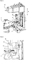
- the figures 1, 2 and 3 present a bending station arranged in front of a plate 2 rotating along a vertical axis, comprising six positions 4 distributed regularly on its outer contour.
- Each fitting 4 forms a horizontal plane receiving the body of a component 6, which is wedged in the direction of the center of the plate 2 on a lateral referencing support, in order to present a defined position.
- Each component 6 has three parallel pins 8, arranged in the same horizontal plane, turned radially outwards. The ends of the pins 8 are interconnected by a plastic overmolding, in order to keep them in position.
- the inner and outer sides of the bending station are defined radially with respect to the center of the turntable 2.
- the bending station comprises several vertical guides along a Z axis, which vertically guide elements moved by an actuator 16 arranged in the upper part, comprising a lower die 8 coming under the pins 6, a support 28 connected to a clamp 12 coming from above the pins close to the body, and an upper die 14 coming above the pins, outside this clamp.
- rotating the plate 2 by a sixth of a turn removes a component 6 after the forming of its pins 8, then presents a new component in the bending station.
- the pins 8 of component 6 must be bent so as to form successively starting from the body, a base remaining in their main plane, then in a perpendicular plane passing through the axis of these pins, profiles of the pins which may be identical or different between these pins.
- the identical bends of the three pins 8 successively form a downward bend along approximately 80 °, then an outward bend leaving the ends of these horizontal pins.
- the lower die 10 comprises successively, starting from the body of the component 6, a horizontal part forming a lower support 20 corresponding to the base of the pins remaining in their main plane, then a lower profile comprising a part inclined downwards at an angle of about 80 °, and then a horizontal part 22.
- the sidewall clamp 12 has a horizontal base forming an upper support 24, fitting above the lower support 20.
- the sidewall clamp 12 is connected to its motorized support 28 along the vertical axis Z, by a guide vertical comprising helical springs 26 surrounding guide rods, applying a downward pressure, giving a small elasticity between these two parts.
- the upper die 14 comprises an upper profile comprising successively, starting from the interior side, a part inclined downwards at an angle of approximately 80 °, then a horizontal part 30, this upper profile corresponding to the lower profile of the lower die 10.
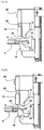
- the figure 4 presents a next step, comprising the raising of the lower die 10 which adjusts its lower support 20 under the base of the pins 8.
- the figures 5 and 6 present the descent of the support 28 which descends the clamp 12, its base 24 applying a clamping force on the pins 8, adjusted within certain limits thanks to the elastic connection given by the springs 26, making it possible to limit this force independently of the tolerances the thickness of the pins. Effective maintenance of the pins 8 is obtained by avoiding transmitting excessive forces to its body, which preserves the integrity of component 6.
- the lower support 20 of the lower die 20 and the base 24 of the clamp 12 comprise an adherent surface treatment making it possible, with moderate pressure, to guarantee the absence of movement of the clamped part of the pins 8 during the operations of camber. In this way we avoids transmitting forces to the housing, traction on pins 8 in particular, which could damage the component.
- the actuator 16 disposed at the top of the bending station comprises a cam 32 sliding horizontally outwards, comprising different profiles which actuate the vertical movements of the lower die 10, of the blank holder 12 and of the upper die 14. On obtains, by a single rapid movement of the cam 32, coordinated actions of the various elements which can be carried out at a very high rate.
- the figures 7 and 8 present the descent of the upper die 14, its upper profile deforming the pins 8 by applying them to the lower profile of the lower die 10, these pins being clamped between these two profiles.
- a force of deformation of the metal pins 8 is obtained, which is transmitted little to the body of the component 6 thanks to the tightening of the base of these pins keeping these bases in position.
- the figure 9 shows the descent of the lower die 10 and the rise of the clamp 10 as well as of the upper die 14, which frees the component 6.
- the turntable 2 can turn in one step to present a new component 6.
- the shapes of the lower and upper profiles of the dies 10, 14, in particular their slopes, are calculated to take account of the plastic and elastic deformations of the pins 8, these latter elastic deformations causing a certain return to the rear of the bends after the opening of these matrices.
- the lower and upper profiles of the dies 10, 14 comprise surface coatings adapted to the characteristics of the metals of the pins 8, in order to obtain the best sliding avoiding metal tearing.
- the bending station is flexible, it can easily perform different types of bending, or receive different types of components, by adapting the shapes of the profiles of the lower 10 and upper 14 dies, as well as the different vertical strokes of these elements.
Abstract
Procédé de cambrage des broches de contact électrique (8) d'un composant (6) fixées à un corps, disposées dans un plan principal, pour obtenir en partant de ce corps une base des broches (8) restant dans le plan principal, puis des cambrages des extrémités formés dans des plans transversaux, ce procédé comportant successivement une étape de positionnement d'une matrice inférieure (10) sous les broches (8), comprenant un appui inférieur ajusté sous la base des broches (8), et un profil inférieur adapté aux cambrages des extrémités à réaliser, puis la descente d'un serre-flanc (12) venant serrer la base des broches (8) au-dessus de l'appui inférieur, et enfin la descente d'une matrice supérieure (14) comprenant un profil supérieur venant sur le profil inférieur en serrant les extrémités des broches (8).Method of bending the electrical contact pins (8) of a component (6) fixed to a body, arranged in a main plane, to obtain, starting from this body, a base of the pins (8) remaining in the main plane, then end bends formed in transverse planes, this method successively comprising a step of positioning a lower die (10) under the pins (8), comprising a lower support fitted under the base of the pins (8), and a profile lower adapted to the bending of the ends to be achieved, then the descent of a clamp (12) which clamps the base of the pins (8) above the lower support, and finally the descent of an upper die (14 ) comprising an upper profile coming on the lower profile by tightening the ends of the pins (8).
Description
La présente invention concerne un procédé de cambrage des broches de contact électrique de composants, ainsi qu'un poste de cambrage mettant en œuvre un tel procédé.The present invention relates to a method of bending the electrical contact pins of components, as well as to a bending station implementing such a method.
Les composants électroniques comprenant un corps équipé de broches pour assurer les contacts électriques, sont de plus en plus utilisés. En particulier les véhicules automobiles comportent un nombre croissant de systèmes électroniques, notamment pour améliorer le contrôle de la combustion des moteurs thermiques ou pour commander des machines électriques de traction de véhicules hybrides ou électriques, afin de réduire la consommation d'énergie et les émissions de gaz polluants, pour aider à la conduite, pour l'automatiser, ou pour de nombreuses autres fonctions afin d'améliorer le confort et la sécurité.Electronic components comprising a body equipped with pins to provide electrical contacts are increasingly used. In particular, motor vehicles include an increasing number of electronic systems, in particular for improving the control of combustion of heat engines or for controlling electric traction machines of hybrid or electric vehicles, in order to reduce energy consumption and emissions. polluting gases, to help driving, to automate it, or for many other functions to improve comfort and safety.
En particulier les capteurs à effet hall sont utilisés dans des systèmes mécatroniques, pour mesurer ou contrôler des déplacements ou des positions. Ces composants peuvent être produits en grande série avec des broches disposées dans un même plan, formant un standard de fabrication. Il faut ensuite suivant les applications réaliser un cambrage et une coupe spécifiques des extrémités des broches, afin d'obtenir le meilleur positionnement de ces broches et de leurs points de contact sur un ensemble, permettant d'optimiser l'encombrement et la masse du système réalisé, ainsi que les coûts de ce système.In particular, hall effect sensors are used in mechatronic systems, to measure or control movements or positions. These components can be mass produced with pins arranged in the same plane, forming a manufacturing standard. It is then necessary, depending on the applications, to make a specific bending and cutting of the ends of the pins, in order to obtain the best positioning of these pins and their points of contact on an assembly, allowing the size and weight of the system to be optimized. realized, as well as the costs of this system.
Toutefois des contraintes mécaniques trop élevées sur le composant, en particulier lors d'actions sur les broches, peuvent l'endommager en entraînant des rebuts qui seront détectés avant ou après le montage sur son ensemble, ce qui augmente les coûts. La mise en oeuvre d'un procédé de cambrage en grande série avec des cadences élevées, sans entraîner de risque de défaillance des composants, pose des problèmes de répétitivité et de fiabilité des opérations.However, too high mechanical stresses on the component, in particular during actions on the pins, can damage it by causing scrap which will be detected before or after assembly as a whole, which increases costs. The implementation of a bending process in large series at high rates, without causing any risk of component failure, poses problems of repeatability and reliability of operations.
De plus le procédé de cambrage doit pouvoir s'adapter facilement à différents types de composants, ou à différentes formes de cambrage des broches d'un même type de composant, en permettant d'utiliser un poste de production flexible pouvant se configurer pour des utilisations variées afin de réduire les coûts.In addition, the bending process must be able to adapt easily to different types of components, or to different forms of bending of pins of the same type of component, making it possible to use a flexible production station that can be configured for uses. varied in order to reduce costs.
La présente invention a notamment pour but d'éviter ces inconvénients de la technique antérieure.The object of the present invention is in particular to avoid these drawbacks of the prior art.
Elle propose à cet effet un procédé de cambrage des broches de contact électrique d'un composant fixées à un corps, disposées dans un plan principal, pour obtenir en partant de ce corps une base des broches restant dans le plan principal, puis des cambrages des extrémités formés dans des plans transversaux, ce procédé étant remarquable en ce qu'il comporte successivement une étape de positionnement d'une matrice inférieure sous les broches, comprenant un appui inférieur ajusté sous la base des broches, et un profil inférieur adapté aux cambrages des extrémités à réaliser, puis la descente d'un serre-flanc venant serrer la base des broches au-dessus de l'appui inférieur, et enfin la descente d'une matrice supérieure comprenant un profil supérieur venant sur le profil inférieur en serrant les extrémités des broches.For this purpose, it proposes a method of bending the electrical contact pins of a component fixed to a body, arranged in a main plane, to obtain, starting from this body, a base of the pins remaining in the main plane, then bending of the pins. ends formed in transverse planes, this method being remarkable in that it successively comprises a step of positioning a lower die under the pins, comprising a lower support adjusted under the base of the pins, and a lower profile adapted to the bends of the pins. ends to be produced, then the descent of a clamp that clamps the base of the pins above the lower support, and finally the descent of an upper die comprising an upper profile coming on the lower profile by tightening the ends some pins.
Un avantage de ce procédé de cambrage est que le serrage préalable de la base des broches entre l'appui inférieur et le serre-flanc supérieur permet de maintenir en position cette base des broches, puis d'appliquer des contraintes sur le reste des broches pour réaliser leur cambrage, sans transmettre ces contraintes au corps du composant.An advantage of this bending process is that the prior tightening of the base of the pins between the lower support and the upper clamp makes it possible to maintain this base of the pins in position, then to apply stresses on the rest of the pins to bend them, without transmitting these stresses to the component body.
On peut de cette manière réaliser en grande série avec une cadence élevée un cambrage particulier de chaque broche des composants. En adaptant les supports du corps pour différents types de composants, ainsi que les deux matrices inférieure et supérieure, on réalise une machine standard pouvant passer différents types de composants, ce qui réduit les coûts.In this way, it is possible to produce in large series with a high rate a particular bending of each component spindle. By adapting the body supports for different types of components, as well as the two lower and upper dies, a standard machine is achieved which can pass different types of components, which reduces costs.
Le procédé de cambrage selon l'invention, ainsi qu'un poste de cambrage mettant en œuvre ce procédé, peuvent comporter de plus une ou plusieurs des caractéristiques suivantes, qui peuvent être combinées entre elles.The bending method according to the invention, as well as a bending station implementing this method, can also include one or more of the following characteristics, which can be combined with one another.
Avantageusement, le procédé applique le serrage de la base des broches par le serre-flanc, par l'intermédiaire d'un ressort.Advantageously, the method applies the tightening of the base of the pins by the clamp, via a spring.
Avantageusement, le procédé réalise les mouvements de positionnement de la matrice inférieure, de descente du serre-flanc et de descente de la matrice supérieure, avec une même came déplacée par un actionneur.Advantageously, the method carries out the movements of positioning the lower die, of lowering the clamp and lowering the upper die, with the same cam moved by an actuator.
L'invention a aussi pour objet un poste de cambrage des broches électriques d'un composant, mettant en œuvre un procédé comprenant l'une quelconque des caractéristiques précédentes, remarquable en ce qu'il comporte des guidages verticaux de la matrice inférieure, du serre-flanc et de la matrice supérieure.The subject of the invention is also a station for bending the electrical pins of a component, implementing a method comprising any one of the preceding characteristics, remarkable in that it comprises vertical guides of the lower die, of the greenhouse. -flank and upper die.
Avantageusement, le poste comporte une liaison élastique entre un support coulissant verticalement, actionné par une motorisation, et le serre-flanc.Advantageously, the station comprises an elastic connection between a vertically sliding support, actuated by a motor, and the side clamp.
Dans ce cas, avantageusement la liaison élastique comporte des ressorts hélicoïdaux entourant des tiges de guidage.In this case, the elastic connection advantageously comprises helical springs surrounding guide rods.
Avantageusement, le poste comporte des cames réalisant les mouvements de positionnement de la matrice inférieure, de descente du serre-flanc et de descente de la matrice supérieure.Advantageously, the station comprises cams carrying out the movements for positioning the lower die, lowering the clamp and lowering the upper die.
Dans ce cas, avantageusement le poste comporte une unique came réalisant les différents mouvements.In this case, the station advantageously comprises a single cam carrying out the various movements.
En particulier, la came peut être est disposée horizontalement en haut du poste de cambrage.In particular, the cam can be is disposed horizontally at the top of the bending station.
Avantageusement, le poste comporte un plateau tournant suivant un axe vertical, comprenant des supports de composants régulièrement espacés sur son contour extérieur.Advantageously, the station comprises a turntable along a vertical axis, comprising component supports regularly spaced on its outer contour.
L'invention sera mieux comprise et d'autres caractéristiques et avantages apparaîtront plus clairement à la lecture de la description ci-après donnée à titre d'exemple, en référence aux dessins annexés dans lesquels :
- [
Fig. 1 ] présente un poste de cambrage mettant en œuvre un procédé selon l'invention pour des composants disposés sur un plateau tournant ; - [
Fig. 2 ] est une vue de détail de ce poste ; - [
Fig. 3 ] est une vue de côté de ce poste ; - [
Fig. 4 ] est une vue de côté présentant l'ajustement de la matrice inférieure sous les broches du composant ; - [
Fig. 5 ] présente en perspective la descente du serre-flanc sur la base des broches ; - [
Fig. 6 ] présente en vue de côté la descente du serre-flanc sur la base des broches ; - [
Fig. 7 ] présente en perspective la descente de la matrice supérieure ; - [
Fig. 8 ] présente en vue de côté, la descente de la matrice supérieure ; et - [
Fig. 9 ] présente le dégagement des broches.
- [
Fig. 1 ] presents a bending station implementing a method according to the invention for components arranged on a turntable; - [
Fig. 2 ] is a detail view of this post; - [
Fig. 3 ] is a side view of this post; - [
Fig. 4 ] is a side view showing the fit of the lower die below the component pins; - [
Fig. 5 ] shows in perspective the descent of the clamp on the base of the pins; - [
Fig. 6 ] shows in side view the descent of the clamp on the base of the pins; - [
Fig. 7 ] presents in perspective the descent of the upper die; - [
Fig. 8 ] shows in side view, the descent of the upper die; and - [
Fig. 9 ] shows the pin clearance.
D'une manière générale le procédé de cambrage selon l'invention peut s'appliquer à tous types de composants, comprenant un corps et au moins une broche à cambrer.In general, the bending method according to the invention can be applied to all types of components, comprising a body and at least one pin to be bent.
Les
Chaque posage 4 forme un plan horizontal recevant le corps d'un composant 6, qui est calé en direction du centre du plateau 2 sur un appui latéral de mise en référence, afin de présenter une position définie. Chaque composant 6 présente trois broches parallèles 8, disposées dans un même plan horizontal, tournées radialement vers l'extérieur. Les extrémités des broches 8 sont reliées entre elles par un surmoulage en matière plastique, afin de les maintenir en position.Each
Par convention les côtés intérieur et extérieur du poste de cambrage, sont définis radialement par rapport au centre du plateau tournant 2.By convention, the inner and outer sides of the bending station are defined radially with respect to the center of the
Le poste de cambrage comporte plusieurs guidages verticaux suivant un axe Z, qui guident verticalement des éléments déplacés par un actionneur 16 disposé en partie supérieure, comprenant une matrice inférieure 8 venant sous les broches 6, un support 28 relié à un serre-flanc 12 venant au-dessus des broches près du corps, et une matrice supérieure 14 venant au-dessus des broches, à l'extérieur de ce serre-flanc.The bending station comprises several vertical guides along a Z axis, which vertically guide elements moved by an
Dans une première étape une rotation du plateau 2 d'un sixième de tour évacue un composant 6 après le formage de ses broches 8, puis présente un nouveau composant dans le poste de cambrage.In a first step, rotating the
Les broches 8 du composant 6 doivent être cambrées de manière à former successivement en partant du corps, une base restant dans leur plan principal, puis dans un plan perpendiculaire passant par l'axe de ces broches, des profils des broches qui peuvent être identiques ou différents entre ces broches.The
Dans cet exemple les cambrages identiques des trois broches 8 forment successivement un pli vers le bas suivant environ 80°, puis un pli vers l'extérieur laissant les extrémités de ces broches horizontales.In this example, the identical bends of the three
La matrice inférieure 10 comporte successivement en partant du corps du composant 6, une partie horizontale formant un appui inférieur 20 correspondant à la base des broches restant dans leur plan principal, puis un profil inférieur comprenant une partie inclinée vers le bas suivant un angle d'environ 80°, et ensuite une partie horizontale 22.The
Le serre-flanc 12 comporte une base horizontale formant un appui supérieur 24, s'ajustant au-dessus de l'appui inférieur 20. Le serre-flanc 12 est relié à son support motorisé 28 suivant l'axe vertical Z, par un guidage vertical comprenant des ressorts hélicoïdaux 26 entourant des tiges de guidage, appliquant une pression vers le bas, donnant une petite élasticité entre ces deux parties.The
La matrice supérieure 14 comporte un profil supérieur comprenant successivement en partant du côté intérieur, une partie inclinée vers le bas suivant un angle d'environ 80°, puis une partie horizontale 30, ce profil supérieur correspondant au profil inférieur de la matrice inférieure 10.The
La
Les
Avantageusement l'appui inférieur 20 de la matrice inférieure 20 et la base 24 du serre-flanc 12 comportent un traitement de surface adhérent permettant avec une pression modérée, de garantir l'absence de mouvement de la partie serrée des broches 8 lors des opérations de cambrage. De cette manière on évite des transmettre des efforts au boîtier, de traction sur les broches 8 notamment, qui pourraient endommager le composant.Advantageously the
L'actionneur 16 disposé en haut du poste de cambrage, comporte une came 32 coulissant horizontalement vers l'extérieur, comprenant différents profils qui actionnent les mouvements verticaux de la matrice inférieure 10, du serre-flanc 12 et de la matrice supérieure 14. On obtient par un seul mouvement rapide de la came 32, des actions coordonnées des différents éléments qui peuvent se faire à une cadence très élevée.The
Les
On obtient un effort de déformation des broches métalliques 8, qui se transmet peu au corps du composant 6 grâce au serrage de la base de ces broches maintenant en position ces bases.A force of deformation of the metal pins 8 is obtained, which is transmitted little to the body of the
La
Avantageusement les formes des profils inférieur et supérieur des matrices 10, 14, notamment leurs pentes, sont calculées pour tenir compte des déformations plastiques et élastiques des broches 8, ces dernières déformations élastiques entraînant un certain rappel en arrière des pliages après l'ouverture de ces matrices.Advantageously, the shapes of the lower and upper profiles of the dies 10, 14, in particular their slopes, are calculated to take account of the plastic and elastic deformations of the
Avantageusement les profils inférieur et supérieur des matrices 10, 14 comportent des revêtements de surface adaptés aux caractéristiques des métaux des broches 8, afin d'obtenir le meilleur glissement évitant des arrachements de métal.Advantageously, the lower and upper profiles of the dies 10, 14 comprise surface coatings adapted to the characteristics of the metals of the
Le poste de cambrage est flexible, il peut effectuer facilement différents types de cambrage, ou recevoir différents types de composants, en adaptant les formes des profils des matrices inférieure 10 et supérieure 14, ainsi que les différentes courses verticales de ces éléments.The bending station is flexible, it can easily perform different types of bending, or receive different types of components, by adapting the shapes of the profiles of the lower 10 and upper 14 dies, as well as the different vertical strokes of these elements.
Claims (9)
Applications Claiming Priority (1)
| Application Number | Priority Date | Filing Date | Title |
|---|---|---|---|
| FR1901493A FR3092956B1 (en) | 2019-02-14 | 2019-02-14 | PROCESS FOR BENDING THE ELECTRICAL SPINDLES OF COMPONENTS |
Publications (1)
| Publication Number | Publication Date |
|---|---|
| EP3697187A1 true EP3697187A1 (en) | 2020-08-19 |
Family
ID=67107770
Family Applications (1)
| Application Number | Title | Priority Date | Filing Date |
|---|---|---|---|
| EP20157059.5A Withdrawn EP3697187A1 (en) | 2019-02-14 | 2020-02-13 | Method for roll bending of electrical pins of components |
Country Status (2)
| Country | Link |
|---|---|
| EP (1) | EP3697187A1 (en) |
| FR (1) | FR3092956B1 (en) |
Cited By (1)
| Publication number | Priority date | Publication date | Assignee | Title |
|---|---|---|---|---|
| CN112547926A (en) * | 2020-11-26 | 2021-03-26 | 童丹桂 | Local forming device of C shaped steel |
Citations (5)
| Publication number | Priority date | Publication date | Assignee | Title |
|---|---|---|---|---|
| US4103718A (en) * | 1977-10-06 | 1978-08-01 | Honeywell Information Systems Inc. | Apparatus for cutting and forming flexible beam leads of an integrated circuit chip |
| GB1580284A (en) * | 1977-05-17 | 1980-12-03 | Weresch T | Apparatus for processing the connecting wires of electrical components |
| JPS5739563A (en) * | 1980-08-21 | 1982-03-04 | Matsushita Electric Ind Co Ltd | Punching and shaping device for carrier film |
| US4957146A (en) * | 1989-03-06 | 1990-09-18 | Harris Corporation | Flatpack preparation machine |
| US5078186A (en) * | 1989-09-28 | 1992-01-07 | Kabushiki Kaisha Toshiba | Lead forming for electronic parts having gull wing type outer leads |
-
2019
- 2019-02-14 FR FR1901493A patent/FR3092956B1/en active Active
-
2020
- 2020-02-13 EP EP20157059.5A patent/EP3697187A1/en not_active Withdrawn
Patent Citations (5)
| Publication number | Priority date | Publication date | Assignee | Title |
|---|---|---|---|---|
| GB1580284A (en) * | 1977-05-17 | 1980-12-03 | Weresch T | Apparatus for processing the connecting wires of electrical components |
| US4103718A (en) * | 1977-10-06 | 1978-08-01 | Honeywell Information Systems Inc. | Apparatus for cutting and forming flexible beam leads of an integrated circuit chip |
| JPS5739563A (en) * | 1980-08-21 | 1982-03-04 | Matsushita Electric Ind Co Ltd | Punching and shaping device for carrier film |
| US4957146A (en) * | 1989-03-06 | 1990-09-18 | Harris Corporation | Flatpack preparation machine |
| US5078186A (en) * | 1989-09-28 | 1992-01-07 | Kabushiki Kaisha Toshiba | Lead forming for electronic parts having gull wing type outer leads |
Cited By (1)
| Publication number | Priority date | Publication date | Assignee | Title |
|---|---|---|---|---|
| CN112547926A (en) * | 2020-11-26 | 2021-03-26 | 童丹桂 | Local forming device of C shaped steel |
Also Published As
| Publication number | Publication date |
|---|---|
| FR3092956B1 (en) | 2022-07-29 |
| FR3092956A1 (en) | 2020-08-21 |
Similar Documents
| Publication | Publication Date | Title |
|---|---|---|
| FR2695586A1 (en) | Welding device and apparatus. | |
| EP3697187A1 (en) | Method for roll bending of electrical pins of components | |
| FR2873945A1 (en) | METHOD AND DEVICE FOR TRANSPORTING A WORKPIECE | |
| EP1968758B1 (en) | Device and method for assembling parts by hemming | |
| EP1611062A2 (en) | Method and device for crowning glass sheets | |
| EP3487646A1 (en) | Shaped-box crimper with electronic cam | |
| FR3020771A1 (en) | GUIDING A FLAN OF TOLE ON A CUTTING MATRIX | |
| FR3076230A1 (en) | CRIMPING DEVICE. | |
| FR2651457A1 (en) | Automated method for the refurbishing and the changing of welding electrodes and device suitable for such a method | |
| EP3445511B1 (en) | Bending tool for motor vehicle crossmember | |
| CN107932065A (en) | The automatic assembly line of automobile B-column | |
| FR3072893B1 (en) | PUNCHING TOOL OF A TIN FLAN AND PUNCHING METHOD USING SUCH A TOOL | |
| EP3538292B1 (en) | Press tooling for sheet metal of relatively large dimensions, notably for motor vehicles | |
| FR3005880A1 (en) | PROCESS FOR PADLING A WORKPIECE, IN PARTICULAR BODY OF A MOTOR VEHICLE, WITH IMPROVED CLAMP SOCKET | |
| FR3046735A1 (en) | MODULAR PADDING TOOLS FOR OPENING OF A MOTOR VEHICLE | |
| EP3130412B1 (en) | Stamping tool with loose guidance | |
| EP2448691A1 (en) | Machine for stamping curved blanks | |
| EP4005696B1 (en) | Device and method for forging a gear tooth on a semi-finished product | |
| FR3032939A1 (en) | METHOD OF MOUNTING A HOOD ON A BODY OF A MOTOR VEHICLE USING A TEMPLATE | |
| FR3092957A1 (en) | MACHINE FOR PREPARING ELECTRICAL SPINDLES OF COMPONENTS | |
| FR3070883B1 (en) | BAKING INSTALLATION FOR PROCESSING PARTS TO SUCCESSIVE POSTS | |
| FR3052693A1 (en) | EVACUATION CONTROL OF MAGNETIC VENTOUSE CUTTING FALLS | |
| EP3548198B1 (en) | Press equipment for forming a collar by trimming | |
| FR2508356A1 (en) | Method of shaping metal articles - uses axially reciprocating punch to push metal in blank between rollers on normal axes | |
| FR3092782A1 (en) | PROCESS FOR PREHENSIONING ELECTRONIC COMPONENTS INCLUDING PINS |
Legal Events
| Date | Code | Title | Description |
|---|---|---|---|
| PUAI | Public reference made under article 153(3) epc to a published international application that has entered the european phase |
Free format text: ORIGINAL CODE: 0009012 |
|
| STAA | Information on the status of an ep patent application or granted ep patent |
Free format text: STATUS: THE APPLICATION HAS BEEN PUBLISHED |
|
| AK | Designated contracting states |
Kind code of ref document: A1 Designated state(s): AL AT BE BG CH CY CZ DE DK EE ES FI FR GB GR HR HU IE IS IT LI LT LU LV MC MK MT NL NO PL PT RO RS SE SI SK SM TR |
|
| AX | Request for extension of the european patent |
Extension state: BA ME |
|
| STAA | Information on the status of an ep patent application or granted ep patent |
Free format text: STATUS: REQUEST FOR EXAMINATION WAS MADE |
|
| 17P | Request for examination filed |
Effective date: 20210219 |
|
| RBV | Designated contracting states (corrected) |
Designated state(s): AL AT BE BG CH CY CZ DE DK EE ES FI FR GB GR HR HU IE IS IT LI LT LU LV MC MK MT NL NO PL PT RO RS SE SI SK SM TR |
|
| STAA | Information on the status of an ep patent application or granted ep patent |
Free format text: STATUS: EXAMINATION IS IN PROGRESS |
|
| 17Q | First examination report despatched |
Effective date: 20220701 |
|
| STAA | Information on the status of an ep patent application or granted ep patent |
Free format text: STATUS: THE APPLICATION HAS BEEN WITHDRAWN |
|
| 18W | Application withdrawn |
Effective date: 20221031 |