EP3697187A1 - Biegeverfahren von elektrischen stiften von komponenten - Google Patents
Biegeverfahren von elektrischen stiften von komponenten Download PDFInfo
- Publication number
- EP3697187A1 EP3697187A1 EP20157059.5A EP20157059A EP3697187A1 EP 3697187 A1 EP3697187 A1 EP 3697187A1 EP 20157059 A EP20157059 A EP 20157059A EP 3697187 A1 EP3697187 A1 EP 3697187A1
- Authority
- EP
- European Patent Office
- Prior art keywords
- pins
- bending
- clamp
- base
- bending station
- Prior art date
- Legal status (The legal status is an assumption and is not a legal conclusion. Google has not performed a legal analysis and makes no representation as to the accuracy of the status listed.)
- Withdrawn
Links
Images


Classifications
-
- H—ELECTRICITY
- H05—ELECTRIC TECHNIQUES NOT OTHERWISE PROVIDED FOR
- H05K—PRINTED CIRCUITS; CASINGS OR CONSTRUCTIONAL DETAILS OF ELECTRIC APPARATUS; MANUFACTURE OF ASSEMBLAGES OF ELECTRICAL COMPONENTS
- H05K13/00—Apparatus or processes specially adapted for manufacturing or adjusting assemblages of electric components
- H05K13/02—Feeding of components
- H05K13/023—Feeding of components with bending or straightening of the terminal leads
- H05K13/024—Straightening or aligning terminal leads
- H05K13/026—Straightening or aligning terminal leads of components having terminal leads in side by side relationship, e.g. using combing elements
Definitions
- the present invention relates to a method of bending the electrical contact pins of components, as well as to a bending station implementing such a method.
- Motor vehicles include an increasing number of electronic systems, in particular for improving the control of combustion of heat engines or for controlling electric traction machines of hybrid or electric vehicles, in order to reduce energy consumption and emissions. polluting gases, to help driving, to automate it, or for many other functions to improve comfort and safety.
- hall effect sensors are used in mechatronic systems, to measure or control movements or positions.
- These components can be mass produced with pins arranged in the same plane, forming a manufacturing standard. It is then necessary, depending on the applications, to make a specific bending and cutting of the ends of the pins, in order to obtain the best positioning of these pins and their points of contact on an assembly, allowing the size and weight of the system to be optimized. realized, as well as the costs of this system.
- the bending process must be able to adapt easily to different types of components, or to different forms of bending of pins of the same type of component, making it possible to use a flexible production station that can be configured for uses. varied in order to reduce costs.
- the object of the present invention is in particular to avoid these drawbacks of the prior art.
- An advantage of this bending process is that the prior tightening of the base of the pins between the lower support and the upper clamp makes it possible to maintain this base of the pins in position, then to apply stresses on the rest of the pins to bend them, without transmitting these stresses to the component body.
- the bending method according to the invention can also include one or more of the following characteristics, which can be combined with one another.
- the method applies the tightening of the base of the pins by the clamp, via a spring.
- the method carries out the movements of positioning the lower die, of lowering the clamp and lowering the upper die, with the same cam moved by an actuator.
- the subject of the invention is also a station for bending the electrical pins of a component, implementing a method comprising any one of the preceding characteristics, remarkable in that it comprises vertical guides of the lower die, of the greenhouse. -flank and upper die.
- the station comprises an elastic connection between a vertically sliding support, actuated by a motor, and the side clamp.
- the elastic connection advantageously comprises helical springs surrounding guide rods.
- the station comprises cams carrying out the movements for positioning the lower die, lowering the clamp and lowering the upper die.
- the station advantageously comprises a single cam carrying out the various movements.
- the cam can be is disposed horizontally at the top of the bending station.
- the station comprises a turntable along a vertical axis, comprising component supports regularly spaced on its outer contour.
- the bending method according to the invention can be applied to all types of components, comprising a body and at least one pin to be bent.
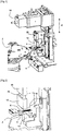
- the figures 1, 2 and 3 present a bending station arranged in front of a plate 2 rotating along a vertical axis, comprising six positions 4 distributed regularly on its outer contour.
- Each fitting 4 forms a horizontal plane receiving the body of a component 6, which is wedged in the direction of the center of the plate 2 on a lateral referencing support, in order to present a defined position.
- Each component 6 has three parallel pins 8, arranged in the same horizontal plane, turned radially outwards. The ends of the pins 8 are interconnected by a plastic overmolding, in order to keep them in position.
- the inner and outer sides of the bending station are defined radially with respect to the center of the turntable 2.
- the bending station comprises several vertical guides along a Z axis, which vertically guide elements moved by an actuator 16 arranged in the upper part, comprising a lower die 8 coming under the pins 6, a support 28 connected to a clamp 12 coming from above the pins close to the body, and an upper die 14 coming above the pins, outside this clamp.
- rotating the plate 2 by a sixth of a turn removes a component 6 after the forming of its pins 8, then presents a new component in the bending station.
- the pins 8 of component 6 must be bent so as to form successively starting from the body, a base remaining in their main plane, then in a perpendicular plane passing through the axis of these pins, profiles of the pins which may be identical or different between these pins.
- the identical bends of the three pins 8 successively form a downward bend along approximately 80 °, then an outward bend leaving the ends of these horizontal pins.
- the lower die 10 comprises successively, starting from the body of the component 6, a horizontal part forming a lower support 20 corresponding to the base of the pins remaining in their main plane, then a lower profile comprising a part inclined downwards at an angle of about 80 °, and then a horizontal part 22.
- the sidewall clamp 12 has a horizontal base forming an upper support 24, fitting above the lower support 20.
- the sidewall clamp 12 is connected to its motorized support 28 along the vertical axis Z, by a guide vertical comprising helical springs 26 surrounding guide rods, applying a downward pressure, giving a small elasticity between these two parts.
- the upper die 14 comprises an upper profile comprising successively, starting from the interior side, a part inclined downwards at an angle of approximately 80 °, then a horizontal part 30, this upper profile corresponding to the lower profile of the lower die 10.
- the figure 4 presents a next step, comprising the raising of the lower die 10 which adjusts its lower support 20 under the base of the pins 8.
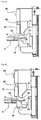
- the figures 5 and 6 present the descent of the support 28 which descends the clamp 12, its base 24 applying a clamping force on the pins 8, adjusted within certain limits thanks to the elastic connection given by the springs 26, making it possible to limit this force independently of the tolerances the thickness of the pins. Effective maintenance of the pins 8 is obtained by avoiding transmitting excessive forces to its body, which preserves the integrity of component 6.
- the lower support 20 of the lower die 20 and the base 24 of the clamp 12 comprise an adherent surface treatment making it possible, with moderate pressure, to guarantee the absence of movement of the clamped part of the pins 8 during the operations of camber. In this way we avoids transmitting forces to the housing, traction on pins 8 in particular, which could damage the component.
- the actuator 16 disposed at the top of the bending station comprises a cam 32 sliding horizontally outwards, comprising different profiles which actuate the vertical movements of the lower die 10, of the blank holder 12 and of the upper die 14. On obtains, by a single rapid movement of the cam 32, coordinated actions of the various elements which can be carried out at a very high rate.
- the figures 7 and 8 present the descent of the upper die 14, its upper profile deforming the pins 8 by applying them to the lower profile of the lower die 10, these pins being clamped between these two profiles.
- a force of deformation of the metal pins 8 is obtained, which is transmitted little to the body of the component 6 thanks to the tightening of the base of these pins keeping these bases in position.
- the figure 9 shows the descent of the lower die 10 and the rise of the clamp 10 as well as of the upper die 14, which frees the component 6.
- the turntable 2 can turn in one step to present a new component 6.
- the shapes of the lower and upper profiles of the dies 10, 14, in particular their slopes, are calculated to take account of the plastic and elastic deformations of the pins 8, these latter elastic deformations causing a certain return to the rear of the bends after the opening of these matrices.
- the lower and upper profiles of the dies 10, 14 comprise surface coatings adapted to the characteristics of the metals of the pins 8, in order to obtain the best sliding avoiding metal tearing.
- the bending station is flexible, it can easily perform different types of bending, or receive different types of components, by adapting the shapes of the profiles of the lower 10 and upper 14 dies, as well as the different vertical strokes of these elements.
Landscapes
- Engineering & Computer Science (AREA)
- Manufacturing & Machinery (AREA)
- Microelectronics & Electronic Packaging (AREA)
- Bending Of Plates, Rods, And Pipes (AREA)
- Manufacture Of Motors, Generators (AREA)
- Manufacturing Of Electrical Connectors (AREA)
Applications Claiming Priority (1)
| Application Number | Priority Date | Filing Date | Title |
|---|---|---|---|
| FR1901493A FR3092956B1 (fr) | 2019-02-14 | 2019-02-14 | Procede de cambrage des broches electriques de composants |
Publications (1)
| Publication Number | Publication Date |
|---|---|
| EP3697187A1 true EP3697187A1 (de) | 2020-08-19 |
Family
ID=67107770
Family Applications (1)
| Application Number | Title | Priority Date | Filing Date |
|---|---|---|---|
| EP20157059.5A Withdrawn EP3697187A1 (de) | 2019-02-14 | 2020-02-13 | Biegeverfahren von elektrischen stiften von komponenten |
Country Status (2)
| Country | Link |
|---|---|
| EP (1) | EP3697187A1 (de) |
| FR (1) | FR3092956B1 (de) |
Cited By (1)
| Publication number | Priority date | Publication date | Assignee | Title |
|---|---|---|---|---|
| CN112547926A (zh) * | 2020-11-26 | 2021-03-26 | 童丹桂 | 一种c型钢局部成型装置 |
Citations (5)
| Publication number | Priority date | Publication date | Assignee | Title |
|---|---|---|---|---|
| US4103718A (en) * | 1977-10-06 | 1978-08-01 | Honeywell Information Systems Inc. | Apparatus for cutting and forming flexible beam leads of an integrated circuit chip |
| GB1580284A (en) * | 1977-05-17 | 1980-12-03 | Weresch T | Apparatus for processing the connecting wires of electrical components |
| JPS5739563A (en) * | 1980-08-21 | 1982-03-04 | Matsushita Electric Ind Co Ltd | Punching and shaping device for carrier film |
| US4957146A (en) * | 1989-03-06 | 1990-09-18 | Harris Corporation | Flatpack preparation machine |
| US5078186A (en) * | 1989-09-28 | 1992-01-07 | Kabushiki Kaisha Toshiba | Lead forming for electronic parts having gull wing type outer leads |
-
2019
- 2019-02-14 FR FR1901493A patent/FR3092956B1/fr active Active
-
2020
- 2020-02-13 EP EP20157059.5A patent/EP3697187A1/de not_active Withdrawn
Patent Citations (5)
| Publication number | Priority date | Publication date | Assignee | Title |
|---|---|---|---|---|
| GB1580284A (en) * | 1977-05-17 | 1980-12-03 | Weresch T | Apparatus for processing the connecting wires of electrical components |
| US4103718A (en) * | 1977-10-06 | 1978-08-01 | Honeywell Information Systems Inc. | Apparatus for cutting and forming flexible beam leads of an integrated circuit chip |
| JPS5739563A (en) * | 1980-08-21 | 1982-03-04 | Matsushita Electric Ind Co Ltd | Punching and shaping device for carrier film |
| US4957146A (en) * | 1989-03-06 | 1990-09-18 | Harris Corporation | Flatpack preparation machine |
| US5078186A (en) * | 1989-09-28 | 1992-01-07 | Kabushiki Kaisha Toshiba | Lead forming for electronic parts having gull wing type outer leads |
Cited By (1)
| Publication number | Priority date | Publication date | Assignee | Title |
|---|---|---|---|---|
| CN112547926A (zh) * | 2020-11-26 | 2021-03-26 | 童丹桂 | 一种c型钢局部成型装置 |
Also Published As
| Publication number | Publication date |
|---|---|
| FR3092956B1 (fr) | 2022-07-29 |
| FR3092956A1 (fr) | 2020-08-21 |
Similar Documents
| Publication | Publication Date | Title |
|---|---|---|
| FR2695586A1 (fr) | Dispositif et appareil de soudage. | |
| EP3697187A1 (de) | Biegeverfahren von elektrischen stiften von komponenten | |
| FR2873945A1 (fr) | Procede et dispositif pour le transport d'une piece | |
| EP1968758B1 (de) | Vorrichtung und Verfahren zur Verbindung von Bauteilen durch Falzen | |
| EP1611062A2 (de) | Verfahren und vorrichtung zum biegen von glasscheiben | |
| EP3487646A1 (de) | Formkastenkrimpzange mit elektronischem nocken | |
| FR3076230A1 (fr) | Dispositif de sertissage. | |
| FR2651457A1 (fr) | Procede automatise pour l'entretien et le changement d'electrodes de soudage et dispositif adapte a un tel procede. | |
| EP3445511B1 (de) | Biegewerkzeug für kraftfahrzeugquerträger | |
| CN107932065A (zh) | 汽车b柱自动组装生产线 | |
| FR3072893B1 (fr) | Outil de poinconnage d’un flan de tole et procede de poinconnage utilisant un tel outil | |
| FR3005880A1 (fr) | Procede d'emboutissage d'une piece, notamment de carrosserie de vehicule automobile, a prise de pince amelioree | |
| FR3046735A1 (fr) | Outillage d’emboutissage modulaire pour ouvant de vehicule automobile | |
| EP3130412B1 (de) | Werkzeug zum tiefziehen mit spannungsloser führung | |
| WO2011001053A1 (fr) | Machine a emboutir les flans galbes | |
| EP4005696B1 (de) | Ausrüstung und verfahren zum schmieden einer zahnradverzahnung auf ein halbfertigprodukt | |
| FR3032939A1 (fr) | Procede de montage d'un capot sur une caisse d'un vehicule automobile a l'aide d'un gabarit | |
| FR3076472A1 (fr) | Triple contre-forme | |
| FR3092957A1 (fr) | Machine de preparation des broches electriques de composants | |
| FR3070883B1 (fr) | Installation d’emboutissage pour transformation de pieces sur des postes successifs | |
| FR3070884A1 (fr) | Reglage de prehenseur d’embouti avec module simulateur. | |
| EP3548198B1 (de) | Presseneinrichtung zur herstellung eines kragens durch beschneiden | |
| FR2508356A1 (fr) | Procede de formage de pieces metalliques et dispositif pour la mise en oeuvre de ce procede | |
| FR3092782A1 (fr) | Procede de prehension de composants electroniques comportant des broches | |
| FR3068627A1 (fr) | Procede d’emboutissage de flan de tole avec ajourage |
Legal Events
| Date | Code | Title | Description |
|---|---|---|---|
| PUAI | Public reference made under article 153(3) epc to a published international application that has entered the european phase |
Free format text: ORIGINAL CODE: 0009012 |
|
| STAA | Information on the status of an ep patent application or granted ep patent |
Free format text: STATUS: THE APPLICATION HAS BEEN PUBLISHED |
|
| AK | Designated contracting states |
Kind code of ref document: A1 Designated state(s): AL AT BE BG CH CY CZ DE DK EE ES FI FR GB GR HR HU IE IS IT LI LT LU LV MC MK MT NL NO PL PT RO RS SE SI SK SM TR |
|
| AX | Request for extension of the european patent |
Extension state: BA ME |
|
| STAA | Information on the status of an ep patent application or granted ep patent |
Free format text: STATUS: REQUEST FOR EXAMINATION WAS MADE |
|
| 17P | Request for examination filed |
Effective date: 20210219 |
|
| RBV | Designated contracting states (corrected) |
Designated state(s): AL AT BE BG CH CY CZ DE DK EE ES FI FR GB GR HR HU IE IS IT LI LT LU LV MC MK MT NL NO PL PT RO RS SE SI SK SM TR |
|
| STAA | Information on the status of an ep patent application or granted ep patent |
Free format text: STATUS: EXAMINATION IS IN PROGRESS |
|
| 17Q | First examination report despatched |
Effective date: 20220701 |
|
| STAA | Information on the status of an ep patent application or granted ep patent |
Free format text: STATUS: THE APPLICATION HAS BEEN WITHDRAWN |
|
| 18W | Application withdrawn |
Effective date: 20221031 |