EP3696923A1 - Steckeranordnung zur herstellung einer lösbaren energie und/ oder datenübertragungsverbindung - Google Patents
Steckeranordnung zur herstellung einer lösbaren energie und/ oder datenübertragungsverbindung Download PDFInfo
- Publication number
- EP3696923A1 EP3696923A1 EP20157602.2A EP20157602A EP3696923A1 EP 3696923 A1 EP3696923 A1 EP 3696923A1 EP 20157602 A EP20157602 A EP 20157602A EP 3696923 A1 EP3696923 A1 EP 3696923A1
- Authority
- EP
- European Patent Office
- Prior art keywords
- contact element
- plug
- socket
- arrangement according
- coupling
- Prior art date
- Legal status (The legal status is an assumption and is not a legal conclusion. Google has not performed a legal analysis and makes no representation as to the accuracy of the status listed.)
- Granted
Links
Images

Classifications
-
- H—ELECTRICITY
- H01—ELECTRIC ELEMENTS
- H01R—ELECTRICALLY-CONDUCTIVE CONNECTIONS; STRUCTURAL ASSOCIATIONS OF A PLURALITY OF MUTUALLY-INSULATED ELECTRICAL CONNECTING ELEMENTS; COUPLING DEVICES; CURRENT COLLECTORS
- H01R24/00—Two-part coupling devices, or either of their cooperating parts, characterised by their overall structure
- H01R24/58—Contacts spaced along longitudinal axis of engagement
-
- G—PHYSICS
- G02—OPTICS
- G02B—OPTICAL ELEMENTS, SYSTEMS OR APPARATUS
- G02B6/00—Light guides; Structural details of arrangements comprising light guides and other optical elements, e.g. couplings
- G02B6/24—Coupling light guides
- G02B6/36—Mechanical coupling means
- G02B6/38—Mechanical coupling means having fibre to fibre mating means
- G02B6/3807—Dismountable connectors, i.e. comprising plugs
- G02B6/3895—Dismountable connectors, i.e. comprising plugs identification of connection, e.g. right plug to the right socket or full engagement of the mating parts
-
- G—PHYSICS
- G06—COMPUTING OR CALCULATING; COUNTING
- G06K—GRAPHICAL DATA READING; PRESENTATION OF DATA; RECORD CARRIERS; HANDLING RECORD CARRIERS
- G06K7/00—Methods or arrangements for sensing record carriers, e.g. for reading patterns
- G06K7/10—Methods or arrangements for sensing record carriers, e.g. for reading patterns by electromagnetic radiation, e.g. optical sensing; by corpuscular radiation
- G06K7/14—Methods or arrangements for sensing record carriers, e.g. for reading patterns by electromagnetic radiation, e.g. optical sensing; by corpuscular radiation using light without selection of wavelength, e.g. sensing reflected white light
- G06K7/1404—Methods for optical code recognition
- G06K7/1408—Methods for optical code recognition the method being specifically adapted for the type of code
- G06K7/1413—1D bar codes
-
- H—ELECTRICITY
- H01—ELECTRIC ELEMENTS
- H01R—ELECTRICALLY-CONDUCTIVE CONNECTIONS; STRUCTURAL ASSOCIATIONS OF A PLURALITY OF MUTUALLY-INSULATED ELECTRICAL CONNECTING ELEMENTS; COUPLING DEVICES; CURRENT COLLECTORS
- H01R13/00—Details of coupling devices of the kinds covered by groups H01R12/70 or H01R24/00 - H01R33/00
- H01R13/46—Bases; Cases
- H01R13/52—Dustproof, splashproof, drip-proof, waterproof, or flameproof cases
- H01R13/5219—Sealing means between coupling parts, e.g. interfacial seal
-
- H—ELECTRICITY
- H01—ELECTRIC ELEMENTS
- H01R—ELECTRICALLY-CONDUCTIVE CONNECTIONS; STRUCTURAL ASSOCIATIONS OF A PLURALITY OF MUTUALLY-INSULATED ELECTRICAL CONNECTING ELEMENTS; COUPLING DEVICES; CURRENT COLLECTORS
- H01R13/00—Details of coupling devices of the kinds covered by groups H01R12/70 or H01R24/00 - H01R33/00
- H01R13/66—Structural association with built-in electrical component
- H01R13/665—Structural association with built-in electrical component with built-in electronic circuit
- H01R13/6683—Structural association with built-in electrical component with built-in electronic circuit with built-in sensor
-
- G—PHYSICS
- G01—MEASURING; TESTING
- G01D—MEASURING NOT SPECIALLY ADAPTED FOR A SPECIFIC VARIABLE; ARRANGEMENTS FOR MEASURING TWO OR MORE VARIABLES NOT COVERED IN A SINGLE OTHER SUBCLASS; TARIFF METERING APPARATUS; MEASURING OR TESTING NOT OTHERWISE PROVIDED FOR
- G01D5/00—Mechanical means for transferring the output of a sensing member; Means for converting the output of a sensing member to another variable where the form or nature of the sensing member does not constrain the means for converting; Transducers not specially adapted for a specific variable
- G01D5/12—Mechanical means for transferring the output of a sensing member; Means for converting the output of a sensing member to another variable where the form or nature of the sensing member does not constrain the means for converting; Transducers not specially adapted for a specific variable using electric or magnetic means
- G01D5/244—Mechanical means for transferring the output of a sensing member; Means for converting the output of a sensing member to another variable where the form or nature of the sensing member does not constrain the means for converting; Transducers not specially adapted for a specific variable using electric or magnetic means influencing characteristics of pulses or pulse trains; generating pulses or pulse trains
-
- H—ELECTRICITY
- H01—ELECTRIC ELEMENTS
- H01R—ELECTRICALLY-CONDUCTIVE CONNECTIONS; STRUCTURAL ASSOCIATIONS OF A PLURALITY OF MUTUALLY-INSULATED ELECTRICAL CONNECTING ELEMENTS; COUPLING DEVICES; CURRENT COLLECTORS
- H01R13/00—Details of coupling devices of the kinds covered by groups H01R12/70 or H01R24/00 - H01R33/00
- H01R13/44—Means for preventing access to live contacts
- H01R13/447—Shutter or cover plate
-
- H—ELECTRICITY
- H01—ELECTRIC ELEMENTS
- H01R—ELECTRICALLY-CONDUCTIVE CONNECTIONS; STRUCTURAL ASSOCIATIONS OF A PLURALITY OF MUTUALLY-INSULATED ELECTRICAL CONNECTING ELEMENTS; COUPLING DEVICES; CURRENT COLLECTORS
- H01R13/00—Details of coupling devices of the kinds covered by groups H01R12/70 or H01R24/00 - H01R33/00
- H01R13/64—Means for preventing incorrect coupling
-
- H—ELECTRICITY
- H01—ELECTRIC ELEMENTS
- H01R—ELECTRICALLY-CONDUCTIVE CONNECTIONS; STRUCTURAL ASSOCIATIONS OF A PLURALITY OF MUTUALLY-INSULATED ELECTRICAL CONNECTING ELEMENTS; COUPLING DEVICES; CURRENT COLLECTORS
- H01R2105/00—Three poles
-
- H—ELECTRICITY
- H01—ELECTRIC ELEMENTS
- H01R—ELECTRICALLY-CONDUCTIVE CONNECTIONS; STRUCTURAL ASSOCIATIONS OF A PLURALITY OF MUTUALLY-INSULATED ELECTRICAL CONNECTING ELEMENTS; COUPLING DEVICES; CURRENT COLLECTORS
- H01R2201/00—Connectors or connections adapted for particular applications
- H01R2201/26—Connectors or connections adapted for particular applications for vehicles
Definitions
- the invention relates to a connector arrangement for establishing a detachable energy and / or data transmission connection, with a housing body and a contact element connected to the housing body, the contact element being rotationally symmetrical with respect to a predetermined insertion direction and having annular contact zones arranged along the predetermined insertion direction.
- Such a connector arrangement is known as a so-called jack connector from, among other things, stage or studio technology and is used there for the transmission of audio signals or supply voltages of comparatively low amperage.
- the construction of the jack plug allows it to rotate freely in an associated coupling socket, so that a cable connected to it is protected from undesired twisting. Due to this property, the use of a jack plug connection is also ideal for establishing a wired energy and / or data transmission connection with an electrically operated agricultural machine, since an associated cable can follow possible changes in the orientation of the agricultural machine due to the free rotation of the plug connection.
- the DE 10 2017 201 544 A1 a wired agricultural machine with a cable drum emerged.
- its course is sensed detected.
- the detection takes place by means of a swiveling measuring sensor, the structure of which is comparatively complex and susceptible to contamination or damage from the outside.
- the connector arrangement according to the invention for establishing a detachable energy and / or data transmission connection comprises a housing body and a contact element connected to the housing body, the contact element being rotationally symmetrical with respect to a predetermined insertion direction and having annular contact zones arranged along the predetermined insertion direction.
- at least one coding means is provided on the contact element which forms an angle code that clearly varies with a rotational position of the contact element.
- the invention makes use of the fact that in the case of a wired, therefore electrically operated agricultural machine, the associated cable is usually detachably attached to one of its two ends by means of a detachable plug connection on a power supply station or another electrically operated agricultural machine. Due to the rotational symmetry of the contact element, this can rotate freely within an associated plug coupling, so that the respective rotational position of the contact element or the angle code resulting therefrom directly indicates the course of the cable attached to it. This information can be used, for example, to control or steer the agricultural machine operated via the cable.
- the connector arrangement is attached to the agricultural machine in such a way that the axis of rotation of the contact element defined by the predetermined plug-in direction coincides with the vertical axis of the agricultural machine. Due to the internal positioning of the at least one coding means when plugged in and its structural integration into the contact element, the arrangement created in this way enables a particularly robust course recording of the energy and / or data transmission cable provided for the electrical operation of the agricultural machine.
- the ring-shaped contact zones can be used for both energy and data transmission.
- These are conductive section rings made of copper of the appropriate width, and these are electrically isolated from one another.
- the conductive section rings can also be hard-coated using a noble metal such as gold or rhodium.
- the connector arrangement can either be designed as an angled connector in which a power and / or data transmission cable entering the housing body runs at right angles to the specified plugging direction, or as a straight plug with a cable entering the housing body in the specified plugging direction.
- the agricultural machine is, for example, an agricultural tractor, a harvesting machine, a forage harvester, a self-propelled sprayer or the like, with several agricultural machines being able to form a fleet that communicates via associated energy and / or data transmission cables.
- An example of such a fleet association can be found in DE 10 2017 217 481 A1 .
- use in connection with construction machines is also conceivable, which, for example, interact with one another in a road construction team or the like.
- the at least one coding means is preferably designed as a bar code arranged in a ring on the contact element.
- the barcode can be arranged in the form of an associated section ring between the annular contact zones of the contact element and have a plurality of coding bars running in the predetermined insertion direction.
- the at least one coding means can be read out without wear by means of contactless sensor detection of the coding bars.
- coding line is to be understood abstractly here. In addition to visually perceptible markings, these can also be correspondingly magnetized areas. The latter are embedded in the section ring encompassed by the at least one coding means and are characterized by particular insensitivity to external soiling and damage. Accordingly, the barcode can be read either optically or magnetically.
- the at least one coding means has at least two bar codes arranged one behind the other in the predetermined insertion direction.
- the bar codes are either redundant or are rotated or offset from one another in such a way that the direction of rotation of the contact element can be determined at the same time.
- the at least one coding means is designed as a sensor ring arranged in a ring on the contact element with magnetization varying continuously along its circumference.
- the course of the magnetization allows direct conclusions to be drawn about the respective direction of rotation of the contact element, whereas the magnetization strength forms a clear measure for its respective rotational position.
- the contact element In order to prevent unintentional loosening of a plug connection made with the plug arrangement, it is possible that there is a circumferential constriction on the contact element for engaging a locking means when making a plug connection with a plug coupling.
- the constriction can in particular be located in the end region of the contact element.
- a sealing means provided on the housing body for producing a dust-tight and / or liquid-tight seat when producing a plug connection with a plug coupling can be present.
- the sealant is In the simplest case, it is a circumferential rubber lip which is pressed tightly against a coupling housing encompassed by the plug coupling.
- a fastening element for attaching a tether can be formed on the housing body of the connector arrangement.
- the tether is stored on a cable drum, for example, and is used to guide or relieve the cable provided for operating the agricultural machine.
- the respective unwinding state of the cable drum allows direct conclusions to be drawn about the current distance between the agricultural machine and the point of origin of the tether and thus ultimately also of the cable. Together with the directional position of the agricultural machine resulting from the rotational position of the contact element, an unambiguous position determination relative to the fixed point of origin is possible.
- a pure distance measuring rope can also be designed to implement a pull-wire sensor.
- the fastening element is in particular formed in one piece as a fastening eye on an upper side of the housing body of the plug arrangement, a snap hook or the like connected to the retaining rope being able to be hooked into the fastening eye.
- a light guide provided on the contact element for broadband or interference-free optical transmission of digital data.
- the at least one coding means additionally comprises a typing code characterizing a function assignment of the contact element.
- the typing code can be stored in an additional RFID identification means which is accommodated as part of the at least one coding means in the housing body of the connector arrangement.
- a plug coupling for receiving the plug arrangement comprises a socket designed complementary to the contact element, spring contacts which can be brought into abutment with the annular contact zones and detection means for reading out the at least one coding means are provided within the socket.
- the detection means are, for example, a reflection light sensor for scanning an optically readable barcode or a Hall sensor for detecting a magnetic field influenced or caused by a magnetically readable barcode or a magnetized sensor ring.
- a protective cover can also be attached to a coupling housing, which cover can be moved from a position that closes the socket towards the outside into a position that releases the socket against a restoring force.
- the protective cover can be attached to the clutch housing in a pivotable or displaceable manner.
- the plug coupling can have a manually operable locking means with a ball coupling, which for releasable engagement in a constriction surrounding the contact element is formed, wherein the locking means is biased in particular in the direction of a locking position.
- the locking means has, in particular, an unlocking piece which can be actuated by hand and which can be brought into an unlocking position that releases the ball coupling.
- a spring element arranged at the front inside the socket can be provided for exerting an ejection force on a contact element located in the socket.
- a sealing means arranged within the socket to be present for producing a dust-tight and / or liquid-tight seat opposite a contact element located in the socket.
- the sealing means is a circumferential rubber ring, which is pressed tightly against the contact element encompassed by the connector assembly when the plug connection is established.
- Fig. 1 shows an embodiment of the connector arrangement according to the invention for establishing a detachable energy and / or data transmission connection with an electrically operated agricultural machine, not shown.
- the connector arrangement 10 designed in the manner of a jack plug, comprises a housing body 12 made of glass fiber reinforced plastic or die-cast metal and a contact element 14 connected to the housing body 12 18, 20 on.
- the annular contact zones 18, 20 are first, second and third conductive section rings 22, 24, 26 for energy transmission and fourth, fifth and sixth conductive section rings 28, 30, 32 for data transmission, these being electrically isolated from one another.
- the conductive section rings 22 to 32 are made of copper and have a width corresponding to the current strength to be transmitted. To protect against oxidation, the conductive section rings 22 to 32 are hard-coated by means of a noble metal such as gold or rhodium.
- a light guide 34 provided on the contact element 14 is also provided for broadband or interference-free optical transmission of digital data available. In the present case, this is located at a front end of the contact element 14.
- the connector arrangement 10 is in the present case designed as an angled connector, i.e. a power and / or data transmission cable 36 entering the housing body 12 runs at right angles to the predetermined insertion direction 16.
- a kink protection 38 made of elastic plastic is used to relieve the mechanical stress on the cable 36.
- At least one coding means 40 is provided on the contact element 14, which forms an angle code that clearly varies with a rotational position 42 of the contact element 14.
- the plug arrangement 10 can rotate freely within an associated plug coupling, so that the respective rotational position 42 of the contact element 14 or the resulting angle code indicates the course of the cable 36 attached to it.
- This information can be used, for example, to control or steer the agricultural machine operated via the cable 36.
- the connector arrangement 10 is attached to the agricultural machine in such a way that the axis of rotation of the contact element 14 defined by the predetermined plug-in direction 16 coincides with the vertical axis of the agricultural machine.
- the at least one coding means 40 is ring-shaped on the contact element 14 arranged first and second bar code 44, 46 formed.
- Each of the two barcodes 44, 46 is arranged in the form of an associated section ring 48, 50 between the annular contact zones 18, 20 of the contact element 14 and has a plurality of coding lines 52, 54 running in the predetermined insertion direction 16.
- coding line is to be understood abstractly here. These are either visually perceptible markings or appropriately magnetized areas. The latter are embedded in the section rings 48, 50 comprised by the at least one coding means 40. Accordingly, the first or second bar code 44, 46 can be read out either optically or magnetically.
- the two bar codes 44, 46 are arranged one behind the other rotated or offset in relation to one another in the predetermined insertion direction 16 in such a way that at the same time a determination of the direction of rotation of the contact element 14 is made possible.
- the at least one coding means 40 comprises a typing code characterizing a function assignment of the contact element 14. This serves to configure the control or drive systems of the agricultural machine operated via the cable 36.
- the typing code is stored in an additional RFID identification means 56, which is accommodated as part of the at least one coding means 40 in the housing body 12 of the plug arrangement 10.
- the at least one coding means 40 instead of the Use of a section ring 48, 50 provided with a bar code 44, 46, a sensor ring arranged in a ring on the contact element 14 with magnetization continuously varying along its circumference. The course of the magnetization allows a direct conclusion about the respective direction of rotation of the contact element 14, whereas the magnetization strength forms a clear measure for its respective rotational position 42.
- the constriction 58 is located in the end region of the contact element 14.
- a sealing means 60 provided on the housing body 12 is used to produce a dust-tight and / or liquid-tight seat when the plug connection is made with the plug coupling 80.
- the sealing means 60 is a circumferential rubber lip 62 that rests against a coupling housing enclosed by the plug coupling 80 is pressed tightly.
- a fastening element 64 for attaching a tether 66 is formed on the housing body 12 of the plug arrangement 10.
- the holding rope 66 is stored, for example, on a rope drum (not shown) and serves to guide or relieve the cable 36 provided for operating the agricultural machine.
- the fastening element 64 is a fastening eye 68 formed in one piece on an upper side of the housing body 12 of the plug arrangement 10, a snap hook 70 or the like connected to the retaining rope 66 being suspended in the fastening eye 68.
- Fig. 2 shows an exemplary embodiment, shown in section, of the plug coupling according to the invention for use with the in Fig. 1 connector assembly 10 shown.
- the plug coupling 80 comprises a socket 82 designed complementary to the contact element 14 for receiving the plug arrangement 10, spring contacts 84, 86 which can be brought into contact with the annular contact zones 18, 20 and detection means 88 for reading out the at least one coding means 40 are provided within the socket 82 .
- the detection means 88 is a reflection light sensor for scanning an optically readable barcode 44, 46 or a Hall sensor for detecting a magnetic field influenced or caused by a magnetically readable barcode 44, 46 or a magnetized sensor ring.
- a protective cover 92 is attached to a coupling housing 90, which can be moved from a position closing the socket 82 to the outside into a position releasing the socket 82 against a restoring force.
- the protective cover 92 is pivotably attached to the clutch housing 90.
- the restoring force is applied by means of a torsion spring 94.
- the plug coupling 80 has a manually operable locking means 96 with a ball coupling 100 which is designed for releasable engagement in the circumferential constriction 58 on the contact element 14, the locking means 96 being a compression spring 98 is biased towards a locking position.
- the locking means 96 has an unlocking piece 102 which can be actuated by hand and which can be brought into an unlocking position that releases the ball coupling 100.
- a spring element 104 arranged at the front inside socket 82 is provided for exerting an ejection force in the event that contact element 14 is located in socket 82.
- a sealing means 106 arranged inside the bushing 82 for producing a dust-tight and / or liquid-tight seat with respect to the contact element 14 is present.
- the sealing means 106 is a circumferential rubber ring 108, which is pressed tightly against the contact element 14 encompassed by the connector assembly 10 when the plug connection is established.
- An RFID reading unit 110 for reading out the typing code stored in the RFID identification means 56 is optionally available.
- the agricultural machine operated via the cable 36 is an agricultural machine Tractor, a harvesting machine, a forage harvester, a self-propelled sprayer or the like can act, whereby several agricultural machines can form a fleet group communicating via associated energy and / or data transmission cables.
- An example of such a fleet association can be found in DE 10 2017 217 481 A1 .
Landscapes
- Physics & Mathematics (AREA)
- Engineering & Computer Science (AREA)
- General Physics & Mathematics (AREA)
- Toxicology (AREA)
- Electromagnetism (AREA)
- General Health & Medical Sciences (AREA)
- Health & Medical Sciences (AREA)
- Artificial Intelligence (AREA)
- Computer Vision & Pattern Recognition (AREA)
- Theoretical Computer Science (AREA)
- Microelectronics & Electronic Packaging (AREA)
- Optics & Photonics (AREA)
- Details Of Connecting Devices For Male And Female Coupling (AREA)
- Connector Housings Or Holding Contact Members (AREA)
Abstract
Description
- Die Erfindung bezieht sich auf eine Steckeranordnung zur Herstellung einer lösbaren Energie- und/oder Datenübertragungsverbindung, mit einem Gehäusekörper und einem mit dem Gehäusekörper verbundenen Kontaktelement, wobei das Kontaktelement bezüglich einer vorgegebenen Steckrichtung rotationssymmetrisch ausgebildet ist und entlang der vorgegebenen Steckrichtung angeordnete ringförmige Kontaktzonen aufweist.
- Eine derartige Steckeranordnung ist als sogenannter Klinkenstecker unter anderem aus der Bühnen- oder Studiotechnik bekannt und dient dort der Übertragung von Audiosignalen oder Versorgungsspannungen vergleichsweise geringer Stromstärke. Die Bauweise des Klinkensteckers erlaubt es diesem, sich in einer zugehörigen Kupplungsdose frei zu drehen, sodass ein mit diesem verbundenes Kabel vor unerwünschtem Verdrillen geschützt ist. Aufgrund dieser Eigenschaft bietet sich die Verwendung einer Klinkensteckerverbindung gerade auch zur Herstellung einer kabelgebundenen Energie- und/oder Datenübertragungsverbindung mit einer elektrisch betriebenen Landmaschine an, da ein zugehöriges Kabel aufgrund der freien Drehbarkeit der Steckverbindung möglichen Orientierungsänderungen der Landmaschine zu folgen vermag.
- In diesem Zusammenhang geht aus der
DE 10 2017 201 544 A1 eine kabelgebunden betriebene Landmaschine mit einer Kabeltrommel hervor. Um ein Überfahren eines von der Kabeltrommel abgespulten Kabelabschnitts zu unterbinden, wird dessen Verlauf sensorisch erfasst. Die Erfassung erfolgt mittels eines schwenkbaren Messfühlers, dessen Aufbau vergleichsweise komplex und für Verschmutzungen bzw. Beschädigungen von außen anfällig ist. - Es ist daher Aufgabe der vorliegenden Erfindung, eine robuste Anordnung zur Erfassung des Verlaufs eines zum elektrischen Betrieb einer Landmaschine vorgesehenen Energie- und/oder Datenübertragungskabels anzugeben.
- Diese Aufgabe wird durch eine Steckeranordnung bzw. eine Steckerkupplung mit den Merkmalen des Patentanspruchs 1 bzw. 11 gelöst.
- Die erfindungsgemäße Steckeranordnung zur Herstellung einer lösbaren Energie- und/oder Datenübertragungsverbindung umfasst einen Gehäusekörper und ein mit dem Gehäusekörper verbundenes Kontaktelement, wobei das Kontaktelement bezüglich einer vorgegebenen Steckrichtung rotationssymmetrisch ausgebildet ist und entlang der vorgegebenen Steckrichtung angeordnete ringförmige Kontaktzonen aufweist. Hierbei ist an dem Kontaktelement wenigstens ein Codierungsmittel vorgesehen, das einen mit einer Rotationsstellung des Kontaktelements eindeutig variierenden Winkelcode bildet.
- Die Erfindung macht sich den Umstand zunutze, dass im Falle einer kabelgebunden, mithin elektrisch betriebenen Landmaschine das zugehörige Kabel üblicherweise an einem seiner beiden Enden mittels einer lösbaren Steckverbindung an einer Energieversorgungsstation oder einer weiteren elektrisch betriebenen Landmaschine lösbar angebracht ist. Aufgrund der Rotationssymmetrie des Kontaktelements kann sich dieses frei innerhalb einer zugehörigen Steckerkupplung drehen, sodass die jeweilige Rotationsstellung des Kontaktelements bzw. der sich hieraus ergebende Winkelcode unmittelbar auf den Verlauf des daran angebrachten Kabels hinweist. Diese Information lässt sich beispielsweise zur Steuerung bzw. Lenkung der über das Kabel betriebenen Landmaschine nutzen. Zu diesem Zweck wird die Steckeranordnung derart an der Landmaschine angebracht, dass die durch die vorgegebene Steckrichtung definierte Drehachse des Kontaktelements mit der Vertikalachse der Landmaschine zusammenfällt. Aufgrund der in gestecktem Zustand innenliegenden Positionierung des wenigstens einen Codierungsmittels sowie seiner baulichen Integration in das Kontaktelement ermöglicht die so geschaffene Anordnung eine besonders robuste Verlaufserfassung des zum elektrischen Betrieb der Landmaschine vorgesehenen Energie- und/oder Datenübertragungskabels.
- Die ringförmigen Kontaktzonen können hierbei gleichermaßen der Energie- wie Datenübertragung dienen. Bei diesen handelt es sich um aus Kupfer bestehende leitende Sektionsringe entsprechender Breite, wobei diese elektrisch voneinander isoliert sind. Zum Schutz vor Oxidation können die leitenden Sektionsringe zusätzlich mittels eines Edelmetalls, wie beispielsweise Gold oder Rhodium, hartbeschichtet sein.
- Die Steckeranordnung kann entweder als Winkelstecker, bei dem ein in den Gehäusekörper eintretendes Energie- und/oder Datenübertragungskabel rechtwinklig gegenüber der vorgegebenen Steckrichtung verläuft, oder aber als gerader Stecker mit einem in Richtung der vorgegebenen Steckrichtung in den Gehäusekörper eintretenden Kabel ausgebildet sein.
- Bei der Landmaschine handelt es sich beispielsweise um einen landwirtschaftlichen Traktor, eine Erntemaschine, einen Feldhäcksler, eine selbstfahrende Spritze oder dergleichen, wobei mehrere Landmaschinen einen über zugehörige Energie- und/oder Datenübertragungskabel kommunizierenden Flottenverband bilden können. Ein Beispiel für einen solchen Flottenverband findet sich in der
DE 10 2017 217 481 A1 . Daneben ist auch eine Verwendung im Zusammenhang mit Baumaschinen denkbar, die beispielsweise in einer Straßenbaukolonne oder dergleichen miteinander agieren. - Vorteilhafte Weiterbildungen der erfindungsgemäßen Steckeranordnung ergeben sich aus den Unteransprüchen.
- Vorzugsweise ist das wenigstens eine Codierungsmittel als an dem Kontaktelement ringförmig angeordneter Strichcode ausgebildet. Der Strichcode kann in Gestalt eines zugehörigen Sektionsrings zwischen den ringförmigen Kontaktzonen des Kontaktelements angeordnet sein und eine Vielzahl von in der vorgegebenen Steckrichtung verlaufende Codierstriche aufweisen. Das Auslesen des wenigstens einen Codierungsmittels kann in diesem Fall verschleißfrei durch kontaktlose sensorische Erfassung der Codierstriche erfolgen.
- Die Bezeichnung "Codierstrich" ist hierbei abstrakt zu verstehen. So kann es sich neben optisch wahrnehmbaren Markierungen auch um entsprechend magnetisierte Bereiche handeln. Letztere sind in den von dem wenigstens einen Codierungsmittel umfassten Sektionsring eingebettet und zeichnen sich durch besondere Unempfindlichkeit gegenüber äußeren Verschmutzungen und Beschädigungen aus. Dementsprechend ist der Strichcode entweder optisch oder magnetisch auslesbar.
- Des Weiteren besteht die Möglichkeit, dass das wenigstens eine Codierungsmittel zumindest zwei in der vorgegebenen Steckrichtung hintereinander angeordnete Strichcodes aufweist. Die Strichcodes sind dabei entweder redundant oder aber derart gegeneinander verdreht bzw. versetzt angeordnet, dass zugleich eine Drehrichtungsbestimmung des Kontaktelements ermöglicht wird.
- Anstelle der Verwendung eines mit einem Strichcode versehenen Sektionsrings ist es auch denkbar, dass das wenigstens eine Codierungsmittel als an dem Kontaktelement ringförmig angeordneter Sensorring mit entlang seines Umfangs kontinuierlich variierender Magnetisierung ausgebildet ist. Der Verlauf der Magnetisierung lässt dabei einen unmittelbaren Rückschluss auf die jeweilige Drehrichtung des Kontaktelements zu, wohingegen die Magnetisierungsstärke ein eindeutiges Maß für dessen jeweilige Rotationsstellung bildet.
- Um ein ungewolltes Lösen einer mit der Steckeranordnung hergestellten Steckverbindung zu unterbinden, ist es möglich, dass eine an dem Kontaktelement umlaufende Einschnürung zur Ineingriffnahme eines Verriegelungsmittels beim Herstellen einer Steckverbindung mit einer Steckerkupplung vorhanden ist. Die Einschnürung kann sich insbesondere im Endbereich des Kontaktelements befinden.
- Daneben kann ein an dem Gehäusekörper vorgesehenes Dichtungsmittel zur Herstellung eines staub- und/oder flüssigkeitsdichten Sitzes beim Herstellen einer Steckverbindung mit einer Steckerkupplung vorhanden sein. Bei dem Dichtungsmittel handelt es sich im einfachsten Fall um eine umlaufende Gummilippe, die gegen ein von der Steckerkupplung umfasstes Kupplungsgehäuse sitzdicht gepresst wird.
- Zusätzlich kann an dem Gehäusekörper der Steckeranordnung ein Befestigungselement zur Anbringung eines Halteseils ausgebildet sein. Das Halteseil ist beispielsweise auf einer Seiltrommel bevorratet und dient der Führung bzw. Entlastung des zum Betrieb der Landmaschine vorgesehenen Kabels. Der jeweilige Abspulzustand der Seiltrommel erlaubt einen unmittelbaren Rückschluss auf den aktuellen Abstand zwischen der Landmaschine und dem Ursprungspunkt des Halteseils und damit letztlich auch des Kabels. Gemeinsam mit der sich aus der Rotationsstellung des Kontaktelements ergebenden Richtungslage der Landmaschine ist eine eindeutige Positionsbestimmung relativ zu dem festen Ursprungspunkt möglich. Alternativ kann anstelle eines Halteseils auch ein reines Abstandsmessseil zur Verwirklichung eines Seilzugsensors ausgebildet sein. Das Befestigungselement ist insbesondere als Befestigungsauge einstückig an einer Oberseite des Gehäusekörpers der Steckeranordnung ausgeformt, wobei sich in das Befestigungsauge ein mit dem Halteseil verbundener Karabinerhaken oder dergleichen einhängen lässt.
- Neben den ringförmigen Kontaktzonen kann auch ein an dem Kontaktelement vorgesehener Lichtleiter zur breitbandigen bzw. störungssicheren optischen Übertragung digitaler Daten vorhanden sein.
- Optional besteht die Möglichkeit, dass das wenigstens eine Codierungsmittel zusätzlich einen eine Funktionsbelegung des Kontaktelements charakterisierenden Typisierungscode umfasst.
- Dieser kann insbesondere zur Konfiguration von über das Kabel kommunizierenden Steuerungs- bzw. Antriebssystemen der Landmaschine dienen. Der Typisierungscode kann in einem zusätzlichen RFID-Identifikationsmittel hinterlegt sein, das als Bestandteil des wenigstens einen Codierungsmittels im Gehäusekörper der Steckeranordnung untergebracht ist.
- Weiterhin umfasst eine Steckerkupplung zur Aufnahme der erfindungsgemäßen Steckeranordnung eine mit dem Kontaktelement komplementär ausgebildete Buchse, wobei innerhalb der Buchse mit den ringförmigen Kontaktzonen in Anlage bringbare Federkontakte sowie Erfassungsmittel zum Auslesen des wenigstens einen Codierungsmittels vorgesehen sind. Bei den Erfassungsmitteln handelt es sich beispielsweise um einen Reflexions-Lichtsensor zum Abtasten eines optisch auslesbaren Strichcodes oder um einen Hallsensor zur Erfassung eines von einem magnetisch auslesbaren Strichcode bzw. einem magnetisierten Sensorring beeinflussten bzw. hervorgerufenen Magnetfelds.
- Zum Schutz der Buchse vor eindringenden Verschmutzungen kann an einem Kupplungsgehäuse des Weiteren ein Schutzdeckel angebracht sein, der sich entgegen einer rückstellenden Kraft aus einer die Buchse nach außen hin verschließenden Position in eine die Buchse freigebende Position verbringen lässt. Der Schutzdeckel kann zu diesem Zweck an dem Kupplungsgehäuse verschwenkbar oder verschiebbar angebracht sein.
- Um die Steckeranordnung innerhalb der Buchse zu sichern, kann die Steckerkupplung ein manuell betätigbares Verriegelungsmittel mit einer Kugelkupplung aufweisen, die zur lösbaren Ineingriffnahme in eine an dem Kontaktelement umlaufende Einschnürung ausgebildet ist, wobei das Verriegelungsmittel insbesondere in Richtung einer Verriegelungsposition vorgespannt ist. Das Verriegelungsmittel weist insbesondere ein mit der Hand betätigbares Entriegelungsstück auf, das sich in eine die Kugelkupplung freigebende Entriegelungsposition verbringen lässt.
- Um ein Lösen einer zwischen Steckeranordnung und Steckerkupplung hergestellten Steckverbindung zu erleichtern bzw. zu unterstützen, kann ein stirnseitig innerhalb der Buchse angeordnetes Federelement zur Ausübung einer Auswurfkraft auf ein in der Buchse befindliches Kontaktelement vorgesehen sein.
- Zusätzlich ist es möglich, dass ein innerhalb der Buchse angeordnetes Dichtungsmittel zur Herstellung eines staub- und/oder flüssigkeitsdichten Sitzes gegenüber einem in der Buchse befindlichen Kontaktelement vorhanden ist. Bei dem Dichtungsmittel handelt es sich im einfachsten Fall um einen umlaufenden Gummiring, der beim Herstellen der Steckverbindung mit der Steckeranordnung gegen das von dieser umfasste Kontaktelement sitzdicht gepresst wird.
- Die erfindungsgemäße Steckeranordnung bzw. Steckerkupplung wird im Folgenden anhand der beigefügten Zeichnungen näher erläutert. Hierbei bezeichnen übereinstimmende Bezugszeichen baulich identische oder bezüglich ihrer Funktion vergleichbare Komponenten. Es zeigen:
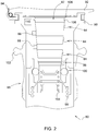
- Fig. 1
- ein Ausführungsbeispiel der erfindungsgemäßen Steckeranordnung zur Herstellung einer lösbaren Energie- und/oder Datenübertragungsverbindung, und
- Fig. 2
- ein im Schnitt wiedergegebenes Ausführungsbeispiel der erfindungsgemäßen Steckerkupplung zum Gebrauch mit der in
Fig. 1 dargestellten Steckeranordnung. -
Fig. 1 zeigt ein Ausführungsbeispiel der erfindungsgemäßen Steckeranordnung zur Herstellung einer lösbaren Energie- und/oder Datenübertragungsverbindung mit einer nicht dargestellten elektrisch betriebenen Landmaschine. - Die nach Art eines Klinkensteckers ausgebildete Steckeranordnung 10 umfasst einen aus glasfaserverstärkten Kunststoff oder Metalldruckguss bestehenden Gehäusekörper 12 und ein mit dem Gehäusekörper 12 verbundenes Kontaktelement 14. Das Kontaktelement 14 ist bezüglich einer vorgegebenen Steckrichtung 16 rotationssymmetrisch ausgebildet und weist mehrere entlang der vorgegebenen Steckrichtung 16 angeordnete ringförmige Kontaktzonen 18, 20 auf.
- Beispielsgemäß handelt es sich bei den ringförmigen Kontaktzonen 18, 20 um erste zweite und dritte leitende Sektionsringe 22, 24, 26 zur Energieübertragung sowie um vierte, fünfte und sechste leitende Sektionsringe 28, 30, 32 zur Datenübertragung, wobei diese elektrisch voneinander isoliert sind. Die leitenden Sektionsringe 22 bis 32 bestehen aus Kupfer und weisen eine der jeweils zu übertragenden Stromstärke entsprechende Breite auf. Zum Schutz vor Oxidation sind die leitenden Sektionsringe 22 bis 32 mittels eines Edelmetalls, wie beispielsweise Gold oder Rhodium, hartbeschichtet.
- Neben den ringförmigen Kontaktzonen 18, 20 ist zusätzlich ein an dem Kontaktelement 14 vorgesehener Lichtleiter 34 zur breitbandigen bzw. störungssicheren optischen Übertragung digitaler Daten vorhanden. Im vorliegenden Fall befindet sich dieser an einem stirnseitigen Ende des Kontaktelements 14.
- Die Steckeranordnung 10 ist vorliegend als Winkelstecker ausgebildet, d.h. ein in den Gehäusekörper 12 eintretendes Energie- und/oder Datenübertragungskabel 36 verläuft rechtwinklig gegenüber der vorgegebenen Steckrichtung 16. Ein aus elastischem Kunststoff bestehender Knickschutz 38 dient dabei der mechanischen Entlastung des Kabels 36.
- Des Weiteren ist an dem Kontaktelement 14 wenigstens ein Codierungsmittel 40 vorgesehen, das einen mit einer Rotationsstellung 42 des Kontaktelements 14 eindeutig variierenden Winkelcode bildet.
- Aufgrund der Rotationssymmetrie des Kontaktelements 14 kann sich die Steckeranordnung 10 frei innerhalb einer zugehörigen Steckerkupplung drehen, sodass die jeweilige Rotationsstellung 42 des Kontaktelements 14 bzw. der sich hieraus ergebende Winkelcode unmittelbar auf den Verlauf des daran angebrachten Kabels 36 hinweist. Diese Information lässt sich beispielsweise zur Steuerung bzw. Lenkung der über das Kabel 36 betriebenen Landmaschine nutzen. Zu diesem Zweck wird die Steckeranordnung 10 derart an der Landmaschine angebracht, dass die durch die vorgegebene Steckrichtung 16 definierte Drehachse des Kontaktelements 14 mit der Vertikalachse der Landmaschine zusammenfällt.
- Entsprechend der Darstellung in
Fig. 1 ist das wenigstens eine Codierungsmittel 40 als an dem Kontaktelement 14 ringförmig angeordneter erster bzw. zweiter Strichcode 44, 46 ausgebildet. Jeder der beiden Strichcodes 44, 46 ist in Gestalt eines zugehörigen Sektionsrings 48, 50 zwischen den ringförmigen Kontaktzonen 18, 20 des Kontaktelements 14 angeordnet und weist eine Vielzahl von in der vorgegebenen Steckrichtung 16 verlaufende Codierstriche 52, 54 auf. - Die Bezeichnung "Codierstrich" ist hierbei abstrakt zu verstehen. So handelt es sich entweder um optisch wahrnehmbare Markierungen oder aber um entsprechend magnetisierte Bereiche. Letztere sind in die von dem wenigstens einen Codierungsmittel 40 umfassten Sektionsringe 48, 50 eingebettet. Dementsprechend ist der erste bzw. zweite Strichcode 44, 46 entweder optisch oder magnetisch auslesbar.
- Die beiden Strichcodes 44, 46 sind in der vorgegebenen Steckrichtung 16 hintereinander derart gegeneinander verdreht bzw. versetzt angeordnet, dass zugleich eine Drehrichtungsbestimmung des Kontaktelements 14 ermöglicht wird.
- Optional umfasst das wenigstens eine Codierungsmittel 40 einen eine Funktionsbelegung des Kontaktelements 14 charakterisierenden Typisierungscode. Dieser dient zur Konfiguration von über das Kabel 36 betriebenen Steuerungs- bzw. Antriebssystemen der Landmaschine. Der Typisierungscode ist in einem zusätzlichen RFID-Identifikationsmittel 56 hinterlegt, das als Bestandteil des wenigstens einen Codierungsmittels 40 im Gehäusekörper 12 der Steckeranordnung 10 untergebracht ist.
- Im Falle einer (nicht dargestellten) alternativen Ausbildung des wenigstens einen Codierungsmittels 40 ist anstelle der Verwendung eines mit einem Strichcode 44, 46 versehenen Sektionsrings 48, 50 ein an dem Kontaktelement 14 ringförmig angeordneter Sensorring mit entlang seines Umfangs kontinuierlich variierender Magnetisierung vorgesehen. Der Verlauf der Magnetisierung lässt dabei einen unmittelbaren Rückschluss auf die jeweilige Drehrichtung des Kontaktelements 14 zu, wohingegen die Magnetisierungsstärke ein eindeutiges Maß für dessen jeweilige Rotationsstellung 42 bildet.
- Um ein ungewolltes Lösen einer mit der Steckeranordnung 10 hergestellten Steckverbindung zu unterbinden, ist eine an dem Kontaktelement 14 umlaufende Einschnürung 58 zur Ineingriffnahme eines Verriegelungsmittels beim Herstellen einer Steckverbindung mit einer in
Fig. 2 wiedergegebenen Steckerkupplung 80 vorhanden. Die Einschnürung 58 befindet sich im Endbereich des Kontaktelements 14. - Ein an dem Gehäusekörper 12 vorgesehenes Dichtungsmittel 60 dient der Herstellung eines staub- und/oder flüssigkeitsdichten Sitzes beim Herstellen der Steckverbindung mit der Steckerkupplung 80. Bei dem Dichtungsmittel 60 handelt es sich um eine umlaufende Gummilippe 62, die gegen ein von der Steckerkupplung 80 umfasstes Kupplungsgehäuse sitzdicht gepresst wird.
- Zusätzlich ist an dem Gehäusekörper 12 der Steckeranordnung 10 ein Befestigungselement 64 zur Anbringung eines Halteseils 66 ausgebildet. Das Halteseil 66 ist beispielsweise auf einer (nicht dargestellten) Seiltrommel bevorratet und dient der Führung bzw. Entlastung des zum Betrieb der Landmaschine vorgesehenen Kabels 36. Das Befestigungselement 64 ist als Befestigungsauge 68 einstückig an einer Oberseite des Gehäusekörpers 12 der Steckeranordnung 10 ausgeformt, wobei in das Befestigungsauge 68 ein mit dem Halteseil 66 verbundener Karabinerhaken 70 oder dergleichen eingehängt ist.
-
Fig. 2 zeigt ein im Schnitt wiedergegebenes Ausführungsbeispiel der erfindungsgemäßen Steckerkupplung zum Gebrauch mit der inFig. 1 dargestellten Steckeranordnung 10. - Die Steckerkupplung 80 umfasst eine mit dem Kontaktelement 14 komplementär ausgebildete Buchse 82 zur Aufnahme der Steckeranordnung 10, wobei innerhalb der Buchse 82 mit den ringförmigen Kontaktzonen 18, 20 in Anlage bringbare Federkontakte 84, 86 sowie Erfassungsmittel 88 zum Auslesen des wenigstens einen Codierungsmittels 40 vorgesehen sind. Bei den Erfassungsmitteln 88 handelt es sich um einen Reflexions-Lichtsensor zum Abtasten eines optisch auslesbaren Strichcodes 44, 46 oder um einen Hallsensor zur Erfassung eines von einem magnetisch auslesbaren Strichcode 44, 46 bzw. einem magnetisierten Sensorring beeinflussten bzw. hervorgerufenen Magnetfelds.
- Zum Schutz der Buchse 82 vor eindringenden Verschmutzungen ist an einem Kupplungsgehäuse 90 ein Schutzdeckel 92 angebracht, der sich entgegen einer rückstellenden Kraft aus einer die Buchse 82 nach außen hin verschließenden Position in eine die Buchse 82 freigebende Position verbringen lässt. Der Schutzdeckel 92 ist zu diesem Zweck an dem Kupplungsgehäuse 90 verschwenkbar angebracht. Die rückstellende Kraft wird mittels einer Torsionsfeder 94 aufgebracht.
- Um die Steckeranordnung 10 innerhalb der Buchse 82 zu sichern, weist die Steckerkupplung 80 ein manuell betätigbares Verriegelungsmittel 96 mit einer Kugelkupplung 100 auf, die zur lösbaren Ineingriffnahme in die an dem Kontaktelement 14 umlaufende Einschnürung 58 ausgebildet ist, wobei das Verriegelungsmittel 96 seitens einer Druckfeder 98 in Richtung einer Verriegelungsposition vorgespannt ist. Das Verriegelungsmittel 96 weist ein mit der Hand betätigbares Entriegelungsstück 102 auf, das sich in eine die Kugelkupplung 100 freigebende Entriegelungsposition verbringen lässt.
- Um ein Lösen einer zwischen Steckeranordnung 10 und Steckerkupplung 80 hergestellten Steckverbindung zu erleichtern bzw. zu unterstützen, ist ein stirnseitig innerhalb der Buchse 82 angeordnetes Federelement 104 zur Ausübung einer Auswurfkraft für den Fall vorgesehen, dass sich das Kontaktelement 14 in der Buchse 82 befindet.
- Zusätzlich ist ein innerhalb der Buchse 82 angeordnetes Dichtungsmittel 106 zur Herstellung eines staub- und/oder flüssigkeitsdichten Sitzes gegenüber dem Kontaktelement 14 vorhanden. Bei dem Dichtungsmittel 106 handelt es sich um einen umlaufenden Gummiring 108, der beim Herstellen der Steckverbindung mit der Steckeranordnung 10 gegen das von dieser umfasste Kontaktelement 14 sitzdicht gepresst wird.
- Optional ist eine RFID-Leseeinheit 110 zum Auslesen des im RFID-Identifikationsmittel 56 hinterlegten Typisierungscodes vorhanden.
- Abschließend sei angemerkt, dass es sich bei der über das Kabel 36 betriebenen Landmaschine um eine landwirtschaftlichen Traktor, eine Erntemaschine, einen Feldhäcksler, eine selbstfahrende Spritze oder dergleichen handeln kann, wobei mehrere Landmaschinen einen über zugehörige Energie- und/oder Datenübertragungskabel kommunizierenden Flottenverband bilden können. Ein Beispiel für einen solchen Flottenverband findet sich in der
DE 10 2017 217 481 A1 .
Claims (15)
- Steckeranordnung zur Herstellung einer lösbaren Energie- und/oder Datenübertragungsverbindung, mit einem Gehäusekörper (12) und einem mit dem Gehäusekörper (12) verbundenen Kontaktelement (14), wobei das Kontaktelement (14) bezüglich einer vorgegebenen Steckrichtung (16) rotationssymmetrisch ausgebildet ist und entlang der vorgegebenen Steckrichtung (16) angeordnete ringförmige Kontaktzonen (18, 20) aufweist, dadurch gekennzeichnet, dass an dem Kontaktelement (14) wenigstens ein Codierungsmittel (40) vorgesehen ist, das einen mit einer Rotationsstellung (42) des Kontaktelements (14) eindeutig variierenden Winkelcode bildet.
- Steckeranordnung nach Anspruch 1, dadurch gekennzeichnet, dass das wenigstens eine Codierungsmittel (40) als an dem Kontaktelement (14) ringförmig angeordneter Strichcode (44, 46) ausgebildet ist.
- Steckeranordnung nach Anspruch 2, dadurch gekennzeichnet, dass der Strichcode (44, 46) entweder optisch oder magnetisch auslesbar ist.
- Steckeranordnung nach wenigstens einem der Ansprüche 1 bis 3, dadurch gekennzeichnet, dass das wenigstens eine Codierungsmittel (40) zumindest zwei in der vorgegebenen Steckrichtung (16) hintereinander angeordnete Strichcodes (44, 46) aufweist.
- Steckeranordnung nach wenigstens einem der Ansprüche 1 bis 4, dadurch gekennzeichnet, dass das wenigstens eine Codierungsmittel (40) als an dem Kontaktelement (14) ringförmig angeordneter Sensorring mit entlang seines Umfangs kontinuierlich variierender Magnetisierung ausgebildet ist.
- Steckeranordnung nach wenigstens einem der Ansprüche 1 bis 5, dadurch gekennzeichnet, dass eine an dem Kontaktelement (14) umlaufende Einschnürung (58) zur Ineingriffnahme eines Verriegelungsmittels (96) beim Herstellen einer Steckverbindung mit einer Steckerkupplung (80) vorhanden ist.
- Steckeranordnung nach wenigstens einem der Ansprüche 1 bis 6, dadurch gekennzeichnet, dass ein an dem Gehäusekörper (12) vorgesehenes Dichtungsmittel (60) zur Herstellung eines staub- und/oder flüssigkeitsdichten Sitzes beim Herstellen einer Steckverbindung mit einer Steckerkupplung (80) vorhanden ist.
- Steckeranordnung nach wenigstens einem der Ansprüche 1 bis 7, dadurch gekennzeichnet, dass an dem Gehäusekörper (12) ein Befestigungselement (64) zur Anbringung eines Halteseils (66) ausgebildet ist.
- Steckeranordnung nach wenigstens einem der Ansprüche 1 bis 8, dadurch gekennzeichnet, dass ein an dem Kontaktelement (14) vorgesehener Lichtleiter (34) zur optischen Übertragung digitaler Daten vorhanden ist.
- Steckeranordnung nach wenigstens einem der Ansprüche 1 bis 9, dadurch gekennzeichnet, dass das wenigstens eine Codierungsmittel (40) zusätzlich einen eine Funktionsbelegung des Kontaktelements (14) charakterisierenden Typisierungscode umfasst.
- Steckerkupplung zur Aufnahme einer Steckeranordnung (10) nach wenigstens einem der Ansprüche 1 bis 10, umfassend eine mit dem Kontaktelement (14) komplementär ausgebildete Buchse (82), wobei innerhalb der Buchse (82) mit den ringförmigen Kontaktzonen (18, 20) in Anlage bringbare Federkontakte (84, 86) sowie Erfassungsmittel (88) zum Auslesen des wenigstens einen Codierungsmittels (40) vorgesehen sind.
- Steckerkupplung nach Anspruch 11, dadurch gekennzeichnet, dass an einem Kupplungsgehäuse (90) ein Schutzdeckel (92) angebracht ist, der sich entgegen einer rückstellenden Kraft aus einer die Buchse (82) nach außen hin verschließenden Position in eine die Buchse (82) freigebende Position verbringen lässt.
- Steckerkupplung nach Anspruch 11 oder 12, gekennzeichnet durch ein manuell betätigbares Verriegelungsmittel (96) mit einer Kugelkupplung (100), die zur lösbaren Ineingriffnahme in eine an dem Kontaktelement (14) umlaufende Einschnürung (58) ausgebildet ist, wobei das Verriegelungsmittel (96) insbesondere in Richtung einer Verriegelungsposition vorgespannt ist.
- Steckerkupplung nach wenigstens einem der Ansprüche 11 bis 13, dadurch gekennzeichnet, dass ein stirnseitig innerhalb der Buchse (82) angeordnetes Federelement (104) zur Ausübung einer Auswurfkraft auf ein in der Buchse (82) befindliches Kontaktelement (14) vorgesehen ist.
- Steckerkupplung nach wenigstens einem der Ansprüche 11 bis 15, dadurch gekennzeichnet, dass ein innerhalb der Buchse (82) angeordnetes Dichtungsmittel (106) zur Herstellung eines staub- und/oder flüssigkeitsdichten Sitzes gegenüber einem in der Buchse (82) befindlichen Kontaktelement (14) vorhanden ist.
Applications Claiming Priority (1)
| Application Number | Priority Date | Filing Date | Title |
|---|---|---|---|
| DE102019202151.4A DE102019202151A1 (de) | 2019-02-18 | 2019-02-18 | Steckeranordnung zur Herstellung einer lösbaren Energie- und/oder Datenübertragungsverbindung |
Publications (2)
| Publication Number | Publication Date |
|---|---|
| EP3696923A1 true EP3696923A1 (de) | 2020-08-19 |
| EP3696923B1 EP3696923B1 (de) | 2025-10-08 |
Family
ID=69631409
Family Applications (1)
| Application Number | Title | Priority Date | Filing Date |
|---|---|---|---|
| EP20157602.2A Active EP3696923B1 (de) | 2019-02-18 | 2020-02-17 | Steckeranordnung zur herstellung einer lösbaren energie und/ oder datenübertragungsverbindung |
Country Status (3)
| Country | Link |
|---|---|
| US (1) | US11374371B2 (de) |
| EP (1) | EP3696923B1 (de) |
| DE (1) | DE102019202151A1 (de) |
Families Citing this family (1)
| Publication number | Priority date | Publication date | Assignee | Title |
|---|---|---|---|---|
| DE102021110150B3 (de) | 2021-04-21 | 2022-09-08 | Ifm Electronic Gmbh | Rundstecker mit Einstellelement |
Citations (7)
| Publication number | Priority date | Publication date | Assignee | Title |
|---|---|---|---|---|
| US6554490B1 (en) * | 1999-05-26 | 2003-04-29 | Sharp Kabushiki Kaisha | Electronic apparatus having communication function using detachable communication cable, capable of reducing power consumption and stable operation |
| US20090110404A1 (en) * | 2007-10-30 | 2009-04-30 | Sony Ericsson Mobile Communications Ab | Connector system with electrical connection and infrared coupling and method |
| US20090286427A1 (en) * | 2008-05-16 | 2009-11-19 | Sony Ericsson Mobile Communications Ab | Connector arrangement having multiple independent connectors |
| US20110116747A1 (en) * | 2009-11-19 | 2011-05-19 | Terlizzi Jeffrey J | Audio plugs with optical and electrical paths |
| US20150318640A1 (en) * | 2014-04-30 | 2015-11-05 | Ford Global Technologies, Llc | High Voltage Connector Assembly |
| DE102017201544A1 (de) | 2017-01-31 | 2018-08-02 | Deere & Company | Anordnung zur Ermittlung einer räumlichen Orientierung eines von einer Kabeltrommel abgespulten Leitungsabschnitts |
| DE102017217481A1 (de) | 2017-09-29 | 2019-04-04 | Deere & Company | Stromversorgungssystem für eine Fahrzeugflotte |
Family Cites Families (8)
| Publication number | Priority date | Publication date | Assignee | Title |
|---|---|---|---|---|
| US2562544A (en) * | 1948-01-31 | 1951-07-31 | Stromberg Carlson Co | Watertight plug and jack |
| US6790070B1 (en) * | 2003-09-10 | 2004-09-14 | The United States Of America As Represented By The Secretary Of The Navy | Apparatus for locking a plug |
| US7570254B2 (en) * | 2004-11-09 | 2009-08-04 | Takahiko Suzuki | Haptic feedback controller, method of controlling the same, and method of transmitting messages that uses a haptic feedback controller |
| US8192234B2 (en) * | 2010-06-03 | 2012-06-05 | Apple Inc. | Audio connector control system |
| CN104425986B (zh) * | 2013-09-11 | 2018-09-07 | 深圳富泰宏精密工业有限公司 | 电子装置 |
| US9484664B1 (en) * | 2015-04-13 | 2016-11-01 | Sprint Communications Company L.P. | Water and ingress resistant audio port |
| KR102482656B1 (ko) * | 2016-07-14 | 2022-12-29 | 삼성전자주식회사 | 이어폰을 이용한 전자 장치의 제어 방법 및 이를 위한 전자 장치 |
| US9948020B1 (en) * | 2017-07-12 | 2018-04-17 | Chia-Hua Lin | Lid-equipped power socket structure |
-
2019
- 2019-02-18 DE DE102019202151.4A patent/DE102019202151A1/de not_active Withdrawn
-
2020
- 2020-02-17 EP EP20157602.2A patent/EP3696923B1/de active Active
- 2020-02-18 US US16/794,186 patent/US11374371B2/en active Active
Patent Citations (7)
| Publication number | Priority date | Publication date | Assignee | Title |
|---|---|---|---|---|
| US6554490B1 (en) * | 1999-05-26 | 2003-04-29 | Sharp Kabushiki Kaisha | Electronic apparatus having communication function using detachable communication cable, capable of reducing power consumption and stable operation |
| US20090110404A1 (en) * | 2007-10-30 | 2009-04-30 | Sony Ericsson Mobile Communications Ab | Connector system with electrical connection and infrared coupling and method |
| US20090286427A1 (en) * | 2008-05-16 | 2009-11-19 | Sony Ericsson Mobile Communications Ab | Connector arrangement having multiple independent connectors |
| US20110116747A1 (en) * | 2009-11-19 | 2011-05-19 | Terlizzi Jeffrey J | Audio plugs with optical and electrical paths |
| US20150318640A1 (en) * | 2014-04-30 | 2015-11-05 | Ford Global Technologies, Llc | High Voltage Connector Assembly |
| DE102017201544A1 (de) | 2017-01-31 | 2018-08-02 | Deere & Company | Anordnung zur Ermittlung einer räumlichen Orientierung eines von einer Kabeltrommel abgespulten Leitungsabschnitts |
| DE102017217481A1 (de) | 2017-09-29 | 2019-04-04 | Deere & Company | Stromversorgungssystem für eine Fahrzeugflotte |
Also Published As
| Publication number | Publication date |
|---|---|
| DE102019202151A1 (de) | 2020-08-20 |
| US20200266590A1 (en) | 2020-08-20 |
| US11374371B2 (en) | 2022-06-28 |
| EP3696923B1 (de) | 2025-10-08 |
Similar Documents
| Publication | Publication Date | Title |
|---|---|---|
| DE102011078329B4 (de) | Anhängevorrichtung für ein Zugfahrzeug | |
| EP0616236B1 (de) | Steckverbindung für einen Lichtwellenleiter | |
| EP1753652B1 (de) | Steckverbindungen | |
| DE19832086B4 (de) | Schalthebeleinheit | |
| DE69409882T2 (de) | Verfahren und Einrichtung zur Visualanzeige der vollständigen Kupplung eines Steckverbinders | |
| WO2011003693A1 (de) | Steckervorrichtung für optisches kabel | |
| DE4227383A1 (de) | Drehbare elektrische verbindungsanordnung | |
| EP1128487A2 (de) | Codierbarer Knickschutz und Codierungsmittel | |
| EP1535765A1 (de) | Anhängerkupplung | |
| EP3696923B1 (de) | Steckeranordnung zur herstellung einer lösbaren energie und/ oder datenübertragungsverbindung | |
| DE2909595A1 (de) | Verbindungsstecker | |
| WO2010055069A1 (de) | Elektrisches gerät | |
| EP2094535B1 (de) | Wickelfederkassette | |
| DE102005045195B4 (de) | Winkelmesser zum Messen des Knickwinkels zwischen einem Zugfahrzeug und einem Anhänger | |
| EP3331102B1 (de) | Steckverbinder mit einer kontaktlosen positionserfassung | |
| DE10143266A1 (de) | Steckeraufnehmer, Steckverbindung, Stecker sowie Gehäuse für eine elektrische Baugruppe mit einem solchen Steckeraufnehmer | |
| EP2508056B1 (de) | Ablage- und Haltevorrichtung für abgekoppelte Leitungen für mobile Arbeitsmaschinen und auswechselbare Ausrüstungen | |
| EP0822622A2 (de) | Elektrische Steckdose mit Kindersicherung | |
| DE102005039081A1 (de) | Modular aufgebautes Drehgeberbaukastensystem | |
| DE9005667U1 (de) | Schalter mit Umhüllung | |
| WO2005040644A1 (de) | Schaltvorrichtung zur übertragung von schaltbefehlen an ein kraftfahrzeuggetriebe | |
| DE202011005089U1 (de) | Ablage- und Haltevorrichtung für abgekoppelte Fluidleitungen für mobile Arbeitsmaschinen und auswechselbare Ausrüstungen | |
| EP4591405A1 (de) | Steckverbindersystem | |
| DE3529718C2 (de) | ||
| DE102024109282A1 (de) | Elektrische Übertragungsvorrichtung zur konduktiven Ladung eines Elektrofahrzeugs, Elektrofahrzeug und Ladestation |
Legal Events
| Date | Code | Title | Description |
|---|---|---|---|
| PUAI | Public reference made under article 153(3) epc to a published international application that has entered the european phase |
Free format text: ORIGINAL CODE: 0009012 |
|
| STAA | Information on the status of an ep patent application or granted ep patent |
Free format text: STATUS: THE APPLICATION HAS BEEN PUBLISHED |
|
| AK | Designated contracting states |
Kind code of ref document: A1 Designated state(s): AL AT BE BG CH CY CZ DE DK EE ES FI FR GB GR HR HU IE IS IT LI LT LU LV MC MK MT NL NO PL PT RO RS SE SI SK SM TR |
|
| AX | Request for extension of the european patent |
Extension state: BA ME |
|
| STAA | Information on the status of an ep patent application or granted ep patent |
Free format text: STATUS: REQUEST FOR EXAMINATION WAS MADE |
|
| 17P | Request for examination filed |
Effective date: 20210219 |
|
| RBV | Designated contracting states (corrected) |
Designated state(s): AL AT BE BG CH CY CZ DE DK EE ES FI FR GB GR HR HU IE IS IT LI LT LU LV MC MK MT NL NO PL PT RO RS SE SI SK SM TR |
|
| STAA | Information on the status of an ep patent application or granted ep patent |
Free format text: STATUS: EXAMINATION IS IN PROGRESS |
|
| 17Q | First examination report despatched |
Effective date: 20210824 |
|
| GRAP | Despatch of communication of intention to grant a patent |
Free format text: ORIGINAL CODE: EPIDOSNIGR1 |
|
| STAA | Information on the status of an ep patent application or granted ep patent |
Free format text: STATUS: GRANT OF PATENT IS INTENDED |
|
| RIC1 | Information provided on ipc code assigned before grant |
Ipc: G01D 5/244 20060101ALN20250516BHEP Ipc: H01R 13/52 20060101ALI20250516BHEP Ipc: G02B 6/38 20060101ALI20250516BHEP Ipc: H01R 13/64 20060101ALI20250516BHEP Ipc: H01R 24/58 20110101AFI20250516BHEP |
|
| INTG | Intention to grant announced |
Effective date: 20250603 |
|
| GRAS | Grant fee paid |
Free format text: ORIGINAL CODE: EPIDOSNIGR3 |
|
| GRAA | (expected) grant |
Free format text: ORIGINAL CODE: 0009210 |
|
| STAA | Information on the status of an ep patent application or granted ep patent |
Free format text: STATUS: THE PATENT HAS BEEN GRANTED |
|
| AK | Designated contracting states |
Kind code of ref document: B1 Designated state(s): AL AT BE BG CH CY CZ DE DK EE ES FI FR GB GR HR HU IE IS IT LI LT LU LV MC MK MT NL NO PL PT RO RS SE SI SK SM TR |
|
| REG | Reference to a national code |
Ref country code: GB Ref legal event code: FG4D Free format text: NOT ENGLISH Ref country code: CH Ref legal event code: F10 Free format text: ST27 STATUS EVENT CODE: U-0-0-F10-F00 (AS PROVIDED BY THE NATIONAL OFFICE) Effective date: 20251008 |
|
| REG | Reference to a national code |
Ref country code: DE Ref legal event code: R096 Ref document number: 502020012030 Country of ref document: DE |
|
| REG | Reference to a national code |
Ref country code: IE Ref legal event code: FG4D Free format text: LANGUAGE OF EP DOCUMENT: GERMAN |
|
| REG | Reference to a national code |
Ref country code: NL Ref legal event code: MP Effective date: 20251008 |
|
| PG25 | Lapsed in a contracting state [announced via postgrant information from national office to epo] |
Ref country code: NL Free format text: LAPSE BECAUSE OF FAILURE TO SUBMIT A TRANSLATION OF THE DESCRIPTION OR TO PAY THE FEE WITHIN THE PRESCRIBED TIME-LIMIT Effective date: 20251008 |
|
| PGFP | Annual fee paid to national office [announced via postgrant information from national office to epo] |
Ref country code: GB Payment date: 20260227 Year of fee payment: 7 |
|
| PG25 | Lapsed in a contracting state [announced via postgrant information from national office to epo] |
Ref country code: ES Free format text: LAPSE BECAUSE OF FAILURE TO SUBMIT A TRANSLATION OF THE DESCRIPTION OR TO PAY THE FEE WITHIN THE PRESCRIBED TIME-LIMIT Effective date: 20251008 |
|
| REG | Reference to a national code |
Ref country code: LT Ref legal event code: MG9D |
|
| PG25 | Lapsed in a contracting state [announced via postgrant information from national office to epo] |
Ref country code: NO Free format text: LAPSE BECAUSE OF FAILURE TO SUBMIT A TRANSLATION OF THE DESCRIPTION OR TO PAY THE FEE WITHIN THE PRESCRIBED TIME-LIMIT Effective date: 20260108 |
|
| PGFP | Annual fee paid to national office [announced via postgrant information from national office to epo] |
Ref country code: DE Payment date: 20260121 Year of fee payment: 7 |
|
| PG25 | Lapsed in a contracting state [announced via postgrant information from national office to epo] |
Ref country code: HR Free format text: LAPSE BECAUSE OF FAILURE TO SUBMIT A TRANSLATION OF THE DESCRIPTION OR TO PAY THE FEE WITHIN THE PRESCRIBED TIME-LIMIT Effective date: 20251008 Ref country code: FI Free format text: LAPSE BECAUSE OF FAILURE TO SUBMIT A TRANSLATION OF THE DESCRIPTION OR TO PAY THE FEE WITHIN THE PRESCRIBED TIME-LIMIT Effective date: 20251008 |
|
| PGFP | Annual fee paid to national office [announced via postgrant information from national office to epo] |
Ref country code: IT Payment date: 20260219 Year of fee payment: 7 |
|
| PG25 | Lapsed in a contracting state [announced via postgrant information from national office to epo] |
Ref country code: RS Free format text: LAPSE BECAUSE OF FAILURE TO SUBMIT A TRANSLATION OF THE DESCRIPTION OR TO PAY THE FEE WITHIN THE PRESCRIBED TIME-LIMIT Effective date: 20260108 |
|
| PG25 | Lapsed in a contracting state [announced via postgrant information from national office to epo] |
Ref country code: IS Free format text: LAPSE BECAUSE OF FAILURE TO SUBMIT A TRANSLATION OF THE DESCRIPTION OR TO PAY THE FEE WITHIN THE PRESCRIBED TIME-LIMIT Effective date: 20260208 |
|
| PGFP | Annual fee paid to national office [announced via postgrant information from national office to epo] |
Ref country code: FR Payment date: 20260225 Year of fee payment: 7 |
|
| PG25 | Lapsed in a contracting state [announced via postgrant information from national office to epo] |
Ref country code: PT Free format text: LAPSE BECAUSE OF FAILURE TO SUBMIT A TRANSLATION OF THE DESCRIPTION OR TO PAY THE FEE WITHIN THE PRESCRIBED TIME-LIMIT Effective date: 20260209 |
|
| PG25 | Lapsed in a contracting state [announced via postgrant information from national office to epo] |
Ref country code: PL Free format text: LAPSE BECAUSE OF FAILURE TO SUBMIT A TRANSLATION OF THE DESCRIPTION OR TO PAY THE FEE WITHIN THE PRESCRIBED TIME-LIMIT Effective date: 20251008 |
|
| PG25 | Lapsed in a contracting state [announced via postgrant information from national office to epo] |
Ref country code: LV Free format text: LAPSE BECAUSE OF FAILURE TO SUBMIT A TRANSLATION OF THE DESCRIPTION OR TO PAY THE FEE WITHIN THE PRESCRIBED TIME-LIMIT Effective date: 20251008 |
|
| PG25 | Lapsed in a contracting state [announced via postgrant information from national office to epo] |
Ref country code: BG Free format text: LAPSE BECAUSE OF FAILURE TO SUBMIT A TRANSLATION OF THE DESCRIPTION OR TO PAY THE FEE WITHIN THE PRESCRIBED TIME-LIMIT Effective date: 20251008 |