EP3696902A1 - Apparatus and method for collecting gas - Google Patents
Apparatus and method for collecting gas Download PDFInfo
- Publication number
- EP3696902A1 EP3696902A1 EP19830675.5A EP19830675A EP3696902A1 EP 3696902 A1 EP3696902 A1 EP 3696902A1 EP 19830675 A EP19830675 A EP 19830675A EP 3696902 A1 EP3696902 A1 EP 3696902A1
- Authority
- EP
- European Patent Office
- Prior art keywords
- secondary battery
- battery
- unit
- gas generated
- collecting
- Prior art date
- Legal status (The legal status is an assumption and is not a legal conclusion. Google has not performed a legal analysis and makes no representation as to the accuracy of the status listed.)
- Granted
Links
Images



Classifications
-
- H—ELECTRICITY
- H01—ELECTRIC ELEMENTS
- H01M—PROCESSES OR MEANS, e.g. BATTERIES, FOR THE DIRECT CONVERSION OF CHEMICAL ENERGY INTO ELECTRICAL ENERGY
- H01M10/00—Secondary cells; Manufacture thereof
- H01M10/42—Methods or arrangements for servicing or maintenance of secondary cells or secondary half-cells
- H01M10/4285—Testing apparatus
-
- G—PHYSICS
- G01—MEASURING; TESTING
- G01N—INVESTIGATING OR ANALYSING MATERIALS BY DETERMINING THEIR CHEMICAL OR PHYSICAL PROPERTIES
- G01N1/00—Sampling; Preparing specimens for investigation
- G01N1/02—Devices for withdrawing samples
- G01N1/22—Devices for withdrawing samples in the gaseous state
-
- G—PHYSICS
- G01—MEASURING; TESTING
- G01N—INVESTIGATING OR ANALYSING MATERIALS BY DETERMINING THEIR CHEMICAL OR PHYSICAL PROPERTIES
- G01N1/00—Sampling; Preparing specimens for investigation
- G01N1/02—Devices for withdrawing samples
- G01N1/22—Devices for withdrawing samples in the gaseous state
- G01N1/2226—Sampling from a closed space, e.g. food package, head space
-
- H—ELECTRICITY
- H01—ELECTRIC ELEMENTS
- H01M—PROCESSES OR MEANS, e.g. BATTERIES, FOR THE DIRECT CONVERSION OF CHEMICAL ENERGY INTO ELECTRICAL ENERGY
- H01M10/00—Secondary cells; Manufacture thereof
- H01M10/42—Methods or arrangements for servicing or maintenance of secondary cells or secondary half-cells
- H01M10/48—Accumulators combined with arrangements for measuring, testing or indicating the condition of cells, e.g. the level or density of the electrolyte
-
- G—PHYSICS
- G01—MEASURING; TESTING
- G01N—INVESTIGATING OR ANALYSING MATERIALS BY DETERMINING THEIR CHEMICAL OR PHYSICAL PROPERTIES
- G01N1/00—Sampling; Preparing specimens for investigation
- G01N1/02—Devices for withdrawing samples
- G01N1/22—Devices for withdrawing samples in the gaseous state
- G01N1/2226—Sampling from a closed space, e.g. food package, head space
- G01N2001/2241—Sampling from a closed space, e.g. food package, head space purpose-built sampling enclosure for emissions
-
- G—PHYSICS
- G01—MEASURING; TESTING
- G01N—INVESTIGATING OR ANALYSING MATERIALS BY DETERMINING THEIR CHEMICAL OR PHYSICAL PROPERTIES
- G01N1/00—Sampling; Preparing specimens for investigation
- G01N1/02—Devices for withdrawing samples
- G01N1/22—Devices for withdrawing samples in the gaseous state
- G01N2001/2244—Exhaled gas, e.g. alcohol detecting
-
- Y—GENERAL TAGGING OF NEW TECHNOLOGICAL DEVELOPMENTS; GENERAL TAGGING OF CROSS-SECTIONAL TECHNOLOGIES SPANNING OVER SEVERAL SECTIONS OF THE IPC; TECHNICAL SUBJECTS COVERED BY FORMER USPC CROSS-REFERENCE ART COLLECTIONS [XRACs] AND DIGESTS
- Y02—TECHNOLOGIES OR APPLICATIONS FOR MITIGATION OR ADAPTATION AGAINST CLIMATE CHANGE
- Y02E—REDUCTION OF GREENHOUSE GAS [GHG] EMISSIONS, RELATED TO ENERGY GENERATION, TRANSMISSION OR DISTRIBUTION
- Y02E60/00—Enabling technologies; Technologies with a potential or indirect contribution to GHG emissions mitigation
- Y02E60/10—Energy storage using batteries
Definitions
- the present invention relates to a gas collecting device and method, and more particularly, to a gas collecting and analyzing device and method of inner gas generated from a plurality of secondary batteries by using an automated collecting device of inner gas generated in a secondary battery.
- a secondary battery is a battery that can be repeatedly used through a discharge process of converting chemical energy into electrical energy and a charging process in the reverse direction thereof.
- the types thereof include nickel-cadmium (Ni-Cd) batteries and nickel-hydrogen (Ni-MH) batteries, lithium-metal batteries, lithium-ion (Li-ion) batteries, and lithium-ion polymer batteries (Li-ion Polymer Battery).
- Ni-Cd nickel-cadmium
- Ni-MH nickel-hydrogen
- lithium-metal batteries lithium-ion (Li-ion) batteries
- lithium-ion polymer batteries Li-ion Polymer Battery
- Lithium secondary batteries include polymer type batteries, circular type batteries, square type batteries, and pouch type batteries.
- the conventional lithium secondary battery has a risk of ignition/explosion when exposed to high temperatures.
- a large current flows within a short time due to overcharge, external short circuit, nail penetration, local crush, or the like, there is a risk of ignition/explosion while the battery is heated by IR heating.
- gas is generated to increase internal pressure of the battery, and the lithium secondary battery may explode or vent the gas at a pressure equal to or greater than a predetermined pressure.
- gases such as carbon dioxide
- the battery having a swelling phenomenon is too thick to be mounted on an electric and electronic device that is designed to be mounted, or it is judged to be defective because of a bulging appearance and loses its value as a product.
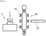
- Fig. 1 shows a conventional collecting device 1 of gas generated in the secondary battery which is connected to a manifold part 10.
- the conventional collecting device 1 of gas generated in the secondary battery collects gas by only one secondary battery mounted in a jig of the collecting device 1 of gas generated in the secondary battery 1 for analysis of inner gas of the secondary battery.
- the gas is analyzed through a gas analyzer 13 connected to the manifold part 10.
- a vacuum pump 11 of the manifold part 10 is connected to a predetermined position of the collecting device 100 of gas generated in the secondary battery, to adjust the collecting device of inner gas generated in the secondary battery equipped with the secondary battery to a vacuum state. Subsequently, the secondary battery is punched through a punching unit to collect gas and then the gas is analyzed through the gas analyzer 13.
- the gas analyzer 13 uses a mass spectrometer or chromatography, but is not limited thereto, and other analyzers or methods may be used to increase the accuracy or precision of gas analysis.
- the conventional method for collecting the generated gas in the battery uses a method in which one type of battery is placed in a sealed jig and punched manually to collect gas. Therefore, there is a need for a device that can more efficiently and quickly collect the gas generated from a larger number of batteries.
- the present invention is devised to solve the above problems of the prior art.
- the present invention is to provide a device for automatically collecting gas generated in the secondary battery that has been developed as an energy source of automotive battery mobile devices and power tools, for example, wherein the device automatically collects the gas generated in a plurality of secondary batteries and automatically injects it into an analysis device for analyzing.
- the automated collecting device of gas generated in a secondary battery of the present invention comprises a plurality of battery holders, each of which is mounted with each of a plurality of secondary batteries; a battery holder tray in which the plurality of battery holders are placed; a collecting unit for coupling to and decoupling from one surface of the secondary battery to be analyzed by moving in a direction perpendicular to the one surface of the secondary battery to be analyzed among the plurality of secondary batteries; and a punching unit for punching the one surface of the secondary battery fixed to the collecting unit by moving in a direction perpendicular to the one surface of the secondary battery to be analyzed in the collecting unit, wherein the battery holder tray may rotate to allow the one surface of the secondary battery to face the collecting unit.
- the automated collecting method of gas generated in a secondary battery of the present invention may be performed in the automated collecting device of gas generated in a secondary battery of the present invention.
- the automated collecting method of gas generated in a secondary battery of the present invention may comprise the steps of rotating the battery holder tray to move a secondary battery to be analyzed to a position facing the collecting unit; approaching the collecting unit to the one surface of the secondary battery to couple; adjusting an interior of the collecting unit to a vacuum state; punching the one surface of the secondary battery with the punching unit; collecting the gas generated in the secondary battery; separating the secondary battery from the collecting unit by injecting nitrogen gas; and spacing the collecting unit apart from the secondary battery and moving a secondary battery to be analyzed next to the position facing the collecting unit.
- the automated collecting method of gas generated in a secondary battery of the present invention may comprise the steps of rotating the battery holder tray by a rotor connected to a first cylinder to move the secondary battery to be analyzed to a position facing the collecting unit, with rotational power of the first cylinder; approaching the collecting unit to the one surface of the secondary battery to couple, with linear power of a second cylinder; adjusting an interior of the collecting unit to a vacuum state; punching the one surface of the secondary battery with the punching unit by linearly moving the punching unit by a crank connected to a third cylinder, with rotational power of the third cylinder; collecting inner gas generated in the secondary battery; separating the secondary battery from the collecting unit by injecting nitrogen gas; and spacing the collecting unit apart from the secondary battery with linear power of the second cylinder and rotating the battery holder tray by the rotor to allow a secondary battery to be analyzed next to face the collecting unit.
- the present invention even with one automated collecting device of gas generated in a secondary battery, it is possible to collect and analyze more efficiently, simply and quickly, in collecting gas generated from a plurality of secondary batteries and analyzing the gas in real time.
- the automated collecting device of gas generated in a secondary battery comprises a plurality of battery holders, each of which is mounted with each of a plurality of secondary batteries; a battery holder tray in which the plurality of battery holders are placed; a collecting unit for coupling to and decoupling from one surface of the secondary battery to be analyzed by moving in a direction perpendicular to the one surface of the secondary battery to be analyzed among the plurality of secondary batteries; and a punching unit for punching the one surface of the secondary battery fixed to the collecting unit by moving in a direction perpendicular to the one surface of the secondary battery to be analyzed in the collecting unit, wherein the battery holder tray may rotate to allow the one surface of the secondary battery to face the collecting unit.
- the automated collecting device of gas generated in a secondary battery of the present invention further comprises a second cylinder connected to the collecting unit and providing power for linear movement; a rotor connected to the battery holder tray to rotate the battery holder tray; a first cylinder connected to the rotor and providing rotational power; a crank connected to the punching unit; and a third cylinder connected to the crank and providing rotational power, wherein the crank converts the rotational power of the third cylinder into power for linear movement of the punching unit.
- the collecting unit may be positioned above the battery holder tray, and the secondary battery or the battery holder may be positioned between the collecting unit and the battery holder tray.
- the collecting unit may comprise a battery holder accommodating unit positioned at a lower end of the collecting unit, the battery holder accommodating unit for accommodating battery holder in its inner space; an accommodating unit of gas generated in the battery which is integrally formed with the battery holder accommodating unit over the battery holder accommodating unit and has a columnar shape, the accommodating unit of gas generated in the battery for accommodating the gas generated in the secondary battery in its inner space; a sealing member provided at a portion where the battery holder accommodating unit and the one surface of the secondary battery contact each other, the sealing member for sealing a space formed by the accommodating unit of gas generated in the battery and the one surface of the secondary battery; an outlet of gas generated in the battery provided at a lateral side of the accommodating unit of gas generated in the battery, wherein the outlet of gas generated in the battery is adjusted to move the inner gas generated in the secondary battery which is released through the accommodating unit of gas generated in the battery from the one surface of the secondary battery to a manifold part or a gas analyzer
- the punching unit may comprise a punching unit rod connected to the crank; and a punching needle connected to a lower end of the punching unit rod, wherein the punching needle moves through the accommodating unit of gas generated in the battery by movement of the punching unit rod due to rotation of the crank, and the punching needle punches the one surface of the secondary battery.
- the punching unit may further comprise a spring connected to an upper end of the punching unit rod, wherein when the crank rotates to move the punching needle downward, the one surface of the secondary battery is punched by moving the punching needle at a high speed with a restoring force of the contracted spring.
- the secondary battery may be any one of a cylinder type battery, a square type battery, a coin cell battery and a pouch type battery.
- the collecting unit may further comprise a nitrogen gas connecting part provided at a lateral side of the accommodating unit of gas generated in the battery and adjusted to connect a nitrogen gas supplying part.
- the collecting unit when the collection of the inner gas generated in the secondary battery to be analyzed is completed, the collecting unit is spaced apart from the one surface of the secondary battery to decouple from the one surface of the secondary battery and the battery holder tray rotates to allow one surface of the secondary battery to be analyzed next to face the collecting unit.
- the automated collecting method of the gas generated in the secondary battery of the present invention may be performed in the automated collecting device of gas generated in the secondary battery of the present invention.
- the automated collecting method of gas generated in a secondary battery of the present invention may comprise the steps of rotating the battery holder tray to move a secondary battery to be analyzed to a position facing the collecting unit; approaching the collecting unit to the one surface of the secondary battery to couple; adjusting an interior of the collecting unit to a vacuum state; punching the one surface of the secondary battery with the punching unit; collecting the gas generated in the secondary battery; separating the secondary battery from the collecting unit by injecting nitrogen gas; and spacing the collecting unit apart from the secondary battery and moving a secondary battery to be analyzed next to the position facing the collecting unit.
- the automated collecting method of gas generated in a secondary battery of the present invention may comprise the steps of rotating the battery holder tray by a rotor connected to a first cylinder to move the secondary battery to be analyzed to a position facing the collecting unit, with rotational power of the first cylinder; approaching the collecting unit to the one surface of the secondary battery to couple, with linear power of a second cylinder; adjusting an interior of the collecting unit to a vacuum state; punching the one surface of the secondary battery with the punching unit by linearly moving the punching unit by a crank connected to a third cylinder, with rotational power of the third cylinder; collecting inner gas generated in the secondary battery; separating the secondary battery from the collecting unit by injecting nitrogen gas; and spacing the collecting unit apart from the secondary battery with linear power of the second cylinder and rotating the battery holder tray by the rotor to allow a secondary battery to be analyzed next to face the collecting unit.
- Fig. 2 is a front view of an automated collecting device of gas generated in the secondary battery according to an embodiment of the present invention.
- Fig. 3 is a front view showing a holder tray.
- Fig. 4 is a front view of an automated collecting device of gas generated in the secondary battery according to another embodiment of the present invention.
- Fig. 5 is a front view showing a punching unit.
- Fig. 6 is a front view showing a punching unit and a crank.
- Figs. 7(a) to (c) illustrate a method of operating the automated collecting device of gas generated in the secondary battery according to Fig. 2 , respectively.
- the automated collecting device 100 of gas generated in the secondary battery according to an embodiment of the present invention may be connected to a manifold part 10 of Fig. 1 and analyzed through a gas analysis device 13.
- the automated collecting device 100 of gas generated in the secondary battery according to one embodiment of the present invention may be directly connected to the gas analysis device without connecting to the manifold part 10.
- the device can be directly connected to the gas analysis device to analyze the gas generated from the plurality of batteries in real time, respectively, without collecting the gas in the manifold part 10. Therefore, there is an advantage that it is possible to analyze immediately without dilution of a sample.
- the automated collecting device of the gas generated in the secondary battery comprises a plurality of battery holders, each of which is mounted with each of a plurality of secondary batteries 20; a battery holder tray 130 in which the plurality of battery holders are placed; a collecting unit 170 for coupling to and decoupling from one surface of the secondary battery 20 to be analyzed by moving in a direction perpendicular to the one surface of the secondary battery 20 to be analyzed among the plurality of secondary batteries 20; and a punching unit 190 for punching the one surface of the secondary battery 20 fixed to the collecting unit 170 by moving in a direction perpendicular to the one surface of the secondary battery 20 to be analyzed in the collecting unit 170.
- the housing has a multi-layered structure, in which each layer may be equipped with components.
- the housing may be formed of, for example, a multilayer structure of a first layer portion 111 and a second layer portion 112, and may include an upper surface portion (not shown) and a lower surface portion (not shown).
- the first layer portion 111 may be positioned below the upper surface portion of the housing and the second layer portion 112 may be positioned below the first layer portion 111, and the lower surface portion may be provided on the bottom of the housing.
- Configuration of the multilayer structure of the housing of the present invention is not limited to the above-described, and various modifications and changes may be made depending on the change of arrangement of the each component of the automated collecting device 100 of gas generated in the secondary battery of the present invention to be described later.
- the upper surface of the battery holder 120 may be provided with a recess (not shown) so that the battery 20 can be mounted and the shape of the recess may correspond to the shape of the battery 20 so that the mounted battery 20 is not separated.
- a rotor 140 is connected to the center of a lower surface of the battery holder tray 130 and a first cylinder 160 is connected to a lower end of the rotor 140.
- the rotor 140 may rotate with rotational power of the first cylinder 160, and thus the battery holder tray 130 may rotate accordingly.
- the lower end of the first cylinder 160 may be fixed to the housing.
- At least one roller 150 is positioned on a lower surface of the battery holder tray 130.
- the lower surface of the battery holder tray 130 may contact the upper surface of the roller 150. Accordingly, when the battery holder tray 130 is rotated by the rotor 140, the battery holder tray 130 may be more smoothly rotated by the roller 150.
- the lower surface of the roller 150 may be fixed to the housing, for example, to the second layer portion 112. Accordingly, the roller 150 also serves to support the battery holder tray 130 and to keep the battery holder tray 130 horizontal.
- the collecting unit 170 to be described later punches the battery 20 the alignment of the tray 130 may be distorted or the tray 130 may be inclined.
- At least one roller 150 should be positioned in a straight line in the vertical direction with the collecting unit 170, and thus it is possible to hold the overall alignment including the tray 130 when punching the battery.
- the roller 150 may be provided in one, but more preferably provided in plural.
- three rollers 150 may be provided, and the surface of the battery holder tray 130 may be stably supported by three-point support.
- the collecting unit 170 for collecting the inner gas generated in the secondary battery may be positioned over the battery holder tray 130.
- the collecting unit 170 according to the present invention does not accommodate the battery 20 therein, but is coupled to the upper surface of the battery 20 to seal the upper surface of the battery 20 and collect the gas generated in the battery 20.
- the battery 20 may be, for example, cylinder type battery, a square type battery, a coin cell battery or a pouch type battery.
- the collecting unit 170 may be moved up and down by a second cylinder 180, and thus may be coupled to and decoupled from the upper surface of the battery 20 accordingly.
- the collecting unit 170 may be moved left and right by the second cylinder 180 and thus may be coupled to and decoupled from the lateral side of the battery 20 accordingly.
- the second cylinder 180 is to provide linear power to the collecting unit 170 so that the collecting unit 170 can be moved linearly.
- the collecting unit 170 may be mounted on the lower surface of the first layer portion 111 of the housing and the second cylinder 180 may be connected to the upper surface of the first layer portion 111.
- the collecting unit 170 mounted on the lower surface of the first layer portion 111 may be moved up and down.
- An upper surface of the battery 20 may refer to one surface of the battery 20 that faces the collecting unit 170 among the surfaces of the battery 20.
- the collecting unit 170 may be positioned over the battery holder tray 130, and the battery 20 or the battery holder 120 may be positioned between the collecting unit 170 and the battery holder tray 130.
- the collecting unit 170 may approach or be spaced apart from the battery 20 by receiving power for linear movement from the second cylinder 180 provided over the collecting unit.
- the battery holder tray 130 may be rotated with a longitudinal axis extending from the upper portion to the lower portion by receiving rotational power from the first cylinder 160 provided below the battery holder tray 130.
- the plurality of battery holders 120 equipped with the secondary batteries 20 may be disposed at the same distance from the rotation center of the battery holder tray 130.
- the battery holder 120 may be disposed along the circumference of the virtual circle whose center is the rotation center of the battery holder tray 130.
- the battery holder 120 may be spaced apart at equal intervals on the circumference of the virtual circle. Therefore, the amount of rotation of the first cylinder 160 may be 360° divided by the number of battery holders 120 provided on the battery holder tray 130.
- the battery holder 120 may be radially symmetrically disposed on the battery holder tray 130 at a constant interval. Each time the first cylinder 160 rotates once, each of batteries may be sequentially positioned below the collecting unit 170.
- the collecting unit 170 includes a battery holder accommodating unit 171 at a lower end of the collecting unit 170.
- the inner space of the battery holder accommodating unit 171 may have a shape that matches the shape of the battery holder 120 to accommodate the battery holder 120.
- the collecting unit 170 includes an accommodating unit 172 of gas generated in the battery 20 for accommodating battery holder in its inner space.
- the accommodating unit 172 of gas generated in the battery is positioned over the battery holder accommodating unit 171 and has a columnar shape and an empty inner space, in which a punching unit rod 192 and a punching needle 193 of the punching unit 190 to be described later can be moved up and down.
- the battery holder accommodating unit 171 and the accommodating unit 172 of gas generated in the battery are integrally formed.
- the battery holder 120 may be accommodated in the battery holder accommodating unit 171 and the upper surface of the battery 20 may be coupled to the lower end of the accommodating unit 172 of gas generated in the battery.
- a sealing member 173 is provided on the circumference of the lower end of the accommodating unit 172 of gas generated in the battery (where the battery holder accommodating unit 171 is contact with the upper surface of the battery 20) to seal the accommodating unit 172 of gas generated in the battery and the upper surface of the battery 20.
- the sealing member 173 may be, for example, an O-ring.
- An outlet 174 of gas generated in the battery is provided at a lateral side of the accommodating unit 172 of gas generated in the battery and adjusted to move the inner gas generated in the battery which is released through the accommodating unit 172 of gas generated in the battery from the upper surface of the battery 20 to a manifold 10.
- the outlet 174 of gas generated in the battery may be equipped with an on-off valve (not shown).
- a lateral side of the accommodating unit 172 of gas generated in the battery is provided with a vacuum pump connecting part 175 to which a vacuum pump 11 is connected to adjust an interior of the accommodating unit 172 of gas generated in the battery to a vacuum state, and a nitrogen gas connecting part 176 for supplying nitrogen gas into the accommodating unit 172 of gas generated in the battery.
- the drawings of the present invention shows a case in which the vacuum pump connecting part 175 and the nitrogen gas connecting part 176 are used in common.
- an on-off valve is provided on the lateral side of the accommodating unit 172 of gas generated in the battery, so that a vacuum pump (not shown) is connected to one opening (175, 176) to adjust an interior of the accommodating unit 172 of gas generated in the battery to a vacuum state and a nitrogen gas supplying part (not shown) is connected to the one opening (175, 176) to supply nitrogen gas to the accommodating unit 172 of gas generated in the battery.
- a T-type connector (not shown) is connected to one opening (175, 176) on the lateral side of the accommodating unit 172 of gas generated in the battery so that the vacuum pump and the nitrogen gas supplying part are connected to the T-type connector, respectively.
- the lateral side of the accommodating unit 172 of gas generated in the battery may be provided with a vacuum pump connecting part 175 and a nitrogen gas connecting part 176, respectively as two openings.
- Each of the vacuum pump connecting part 175 and the nitrogen gas connecting part 176 may be equipped with an on-off valve (not shown).
- the collecting unit 170 is also provided with a punching unit 190 for punching the upper surface of the battery 20.
- the punching unit 190 may move up and down by a crank 200.
- the third cylinder 210 rotates to allow the crank 200 connected to the third cylinder 210 to be rotated.
- the punching unit 190 connected to the crank through the connecting rod 201 is moved vertically (up and down). That is, the rotational power of the third cylinder 210 by the crank 200 may be converted into the linear power for reciprocating the punching unit 190 up and down.
- the connecting rod 201 may be roughly composed of a first portion 201 a connected to the crank 200 and a second portion 201b connected to the punching unit 190.
- the first portion 201a may be an elliptic or circular disk.
- the rotation axis of the crank 200 may be connected to be perpendicular to the surface of the first portion 201a, and may be connected to be spaced apart from the center of the first portion 201a.
- One end of the second portion 201b is fixed to the punching unit 190, and the other end of the second portion 201b may slide in contact with the circumference of the first portion 201a.
- the first portion 201a of the connecting rod 201 fixed to the crank 200 rotates, the second portion 201b of the connecting rod 201 is pushed out so that the punching unit 190 moves linearly to punch a hole in the battery 20.
- first portion 201a and the second portion 201b of the connecting rod 201 may be integrally formed.
- Figs. 7(a) and 7(c) show a case where the punching unit 190 is raised, and Fig. 7(b) shows a case where the punching unit 190 is lowered.
- the third cylinder 210 may be supported on the lower surface of the first layer portion 111 through the third cylinder fixing member 211.
- the punching unit rod 192 of the punching unit 190 is connected to the connecting rod 201 of the crank 200.
- the punching needle 193 is connected to the lower end of the punching unit rod 192, so that the punching needle 193 is moved up and down by the up and down movement of the punching unit rod 192 due to the rotation of the crank 200.
- the punching unit rod 192 and the punching needle 193 may be moved through the inside of the accommodating unit 172 of gas generated in the battery so that the punching needle 193 can be moved to the upper surface of the battery 20.
- the punching unit 190 moves downward to the upper surface of the battery 20 and the upper surface of the battery 20 is punched with the punching needle 193 and then the punching unit 190 moves upward, the inner gas generated in the battery 20 moves from the hole on the upper surface of the battery 20 into the accommodating unit 172 of gas generated in the battery.
- the circumstance of the punching unit rod 192 is provided with a sealing member 195, such as an O-ring so that the inner gas generated in the battery 20 does not move to the spring 194 connected to the punching unit rod 192.
- the sealing member 195 of the punching unit rod 192 may be provided in plural.
- the plurality of sealing members 195 of the punching rods 192 may be disposed to be spaced apart from each other by a certain distance along the longitudinal direction of the punching unit rod 195.
- the accommodating unit 172 of gas generated in the battery may have a closed space that is blocked by the sealing member 195 around the punching unit rod 192 and the sealing member 173 contacting the upper surface of the battery 20 from the outside. That is, the sealing members 173 and 195 at two positions may prevent the gas from leaking to the outside and allow the gas to be collected in the accommodating unit 172 of gas generated in the battery.
- a spring 194 is connected to the upper end of the punching unit rod 192, so that the punching needle 193 can be rapidly moved downward by a restoring force of the spring 194 which is contracted when the crank 200 rotates to move the punching needle 193 downward. Accordingly, the upper surface of the battery 20 can be punched by the punching needle 193 instantaneously. In addition, it is possible to limit vertical movement distance of the punching needle (193) by the spring 194.
- a step of rotating the battery holder tray 130 to place the battery 20 to be analyzed below the collecting unit 170 is performed. That is, the battery 20 to be analyzed is properly positioned below the collecting unit 170 by rotating the battery holder tray 130.
- a step of coupling the collecting unit 170 to the upper surface of the battery 20 by moving downward by the second cylinder 180 is performed. That is, the collecting unit 170 is moved downward by the second cylinder 180 to be accurately fixed to the upper surface of the battery 20, and the upper surface of the battery 20 is sealed by the sealing member 173.
- a step of adjusting an interior of the accommodating unit 172 of gas generated in the battery to a vacuum state is performed. That is, the on-off valve of the vacuum pump connecting part 175 to which the vacuum pump 11 is connected is opened to adjust an interior of the accommodating unit 172 of gas generated in the battery to a vacuum state.
- the punching unit 190 may be elevated.
- a step of punching the upper surface of the battery 20 by moving the punching needle 193 downward by rotating the crank 200 is performed. That is, as the crank 200 rotates by the third cylinder 210, the punching needle 193 is rapidly moved downward to punch the upper surface of the battery 20 strongly together with a force of the spring 194. At this time, the restoring force of the spring 194 which is contracted with the rotation of the crank 200 is added, so that the punching needle 193 can be moved downward rapidly.
- all of the valves of outlet 174 of gas generated in the battery, the vacuum pump connecting part 175, and the nitrogen gas connecting part 176 may be closed.
- a step of collecting the inner gas generated gas in the battery 20 ( Fig. 7(c) ) is performed. That is, as the crank 200 rotates, the punching needle 193 moves upward and returns to its original state. At this time, since the spring 194 is contracted, the speed at which the punching needle 193 moves upward is slower than the speed at which punching needle 193 moves downward. When the punching needle 193 moves upward, the inner gas generated in the battery 20 is moved from the punched hole on the upper surface of the battery 20 into the accommodating unit 172 of gas generated in the battery and collected through the outlet 174 of gas generated in the battery.
- a step of separating the battery 20 from the collecting unit 170 by injecting nitrogen gas is performed. That is, when the collection of the inner gas generated in the battery 20 is completed, the on-off valve of the nitrogen gas connecting part 176 is opened to inject nitrogen gas into the accommodating unit 172 of gas generated in the battery. As a result, the battery 20 that is in close contact with the sealing member 173 is separated.
- a step of moving the collecting unit 170 upward by the second cylinder 180 and positioning a secondary battery 20 to be analyzed next below the collecting unit 170 is performed. That is, after the collecting unit 170 is moved upward by the second cylinder 180, the battery holder tray 130 is rotated so that the battery 20 to be analyzed next is positioned right below the collecting unit 170. The same process is performed as described above with respect to the battery 20 to be analyzed next.
Landscapes
- Chemical & Material Sciences (AREA)
- Engineering & Computer Science (AREA)
- Life Sciences & Earth Sciences (AREA)
- Health & Medical Sciences (AREA)
- General Chemical & Material Sciences (AREA)
- Electrochemistry (AREA)
- Chemical Kinetics & Catalysis (AREA)
- Manufacturing & Machinery (AREA)
- Physics & Mathematics (AREA)
- General Health & Medical Sciences (AREA)
- General Physics & Mathematics (AREA)
- Immunology (AREA)
- Pathology (AREA)
- Biochemistry (AREA)
- Analytical Chemistry (AREA)
- Molecular Biology (AREA)
- Biomedical Technology (AREA)
- Sampling And Sample Adjustment (AREA)
- Secondary Cells (AREA)
- Battery Mounting, Suspending (AREA)
Abstract
Description
- This application claims the benefit of priorities to Korean Patent Application Nos.
10-2018-0077665, filed on July 4, 2018 10-2019-0056805, filed on April 30, 2019 10-2019-0075688, filed on June 25, 2019 - The present invention relates to a gas collecting device and method, and more particularly, to a gas collecting and analyzing device and method of inner gas generated from a plurality of secondary batteries by using an automated collecting device of inner gas generated in a secondary battery.
- In general, a secondary battery is a battery that can be repeatedly used through a discharge process of converting chemical energy into electrical energy and a charging process in the reverse direction thereof. The types thereof include nickel-cadmium (Ni-Cd) batteries and nickel-hydrogen (Ni-MH) batteries, lithium-metal batteries, lithium-ion (Li-ion) batteries, and lithium-ion polymer batteries (Li-ion Polymer Battery). Among these secondary batteries, lithium secondary batteries having high energy density and voltage, long cycle life, and low self discharge rate are commercially used and widely used. Lithium secondary batteries include polymer type batteries, circular type batteries, square type batteries, and pouch type batteries.
- However, the conventional lithium secondary battery has a risk of ignition/explosion when exposed to high temperatures. In addition, when a large current flows within a short time due to overcharge, external short circuit, nail penetration, local crush, or the like, there is a risk of ignition/explosion while the battery is heated by IR heating. As an example, as a result of the reaction between electrolyte and electrodes, gas is generated to increase internal pressure of the battery, and the lithium secondary battery may explode or vent the gas at a pressure equal to or greater than a predetermined pressure.
- Various kinds of gases, such as hydrogen, oxygen, nitrogen, carbon monoxide, carbon dioxide, hydrocarbon such as CnH2n-2 (n = 2 ∼ 5), CnH2n (n = 2 ∼ 5) and CnH2n+2 (n = 1 ∼ 5) and other organic gas species may be generated depending on the reaction in a lithium secondary battery. Internally generated gases, such as carbon dioxide, are reversible depending on the conditions, returning back to their original material upon charging, but usually remain in a gaseous phase in the battery to increase internal pressure and cause a swelling phenomenon that causes the battery to swell. The battery having a swelling phenomenon is too thick to be mounted on an electric and electronic device that is designed to be mounted, or it is judged to be defective because of a bulging appearance and loses its value as a product.
- Therefore, it is very important to collect and accurately analyze the gas generated in the secondary battery. Various gases are generated during the operation of lithium ion batteries, and information on the composition and content of the generated gases is useful for developing battery materials, optimizing battery manufacturing processes, and identifying causes of battery failure.
- First,
Fig. 1 shows a conventional collecting device 1 of gas generated in the secondary battery which is connected to amanifold part 10. Referring toFig. 1 , the conventional collecting device 1 of gas generated in the secondary battery collects gas by only one secondary battery mounted in a jig of the collecting device 1 of gas generated in the secondary battery 1 for analysis of inner gas of the secondary battery. As a result, the gas is analyzed through agas analyzer 13 connected to themanifold part 10. - That is, a
vacuum pump 11 of themanifold part 10 is connected to a predetermined position of thecollecting device 100 of gas generated in the secondary battery, to adjust the collecting device of inner gas generated in the secondary battery equipped with the secondary battery to a vacuum state. Subsequently, the secondary battery is punched through a punching unit to collect gas and then the gas is analyzed through thegas analyzer 13. - The
gas analyzer 13 uses a mass spectrometer or chromatography, but is not limited thereto, and other analyzers or methods may be used to increase the accuracy or precision of gas analysis. - However, the conventional method for collecting the generated gas in the battery uses a method in which one type of battery is placed in a sealed jig and punched manually to collect gas. Therefore, there is a need for a device that can more efficiently and quickly collect the gas generated from a larger number of batteries.
- The present invention is devised to solve the above problems of the prior art. The present invention is to provide a device for automatically collecting gas generated in the secondary battery that has been developed as an energy source of automotive battery mobile devices and power tools, for example, wherein the device automatically collects the gas generated in a plurality of secondary batteries and automatically injects it into an analysis device for analyzing.
- The automated collecting device of gas generated in a secondary battery of the present invention comprises a plurality of battery holders, each of which is mounted with each of a plurality of secondary batteries; a battery holder tray in which the plurality of battery holders are placed; a collecting unit for coupling to and decoupling from one surface of the secondary battery to be analyzed by moving in a direction perpendicular to the one surface of the secondary battery to be analyzed among the plurality of secondary batteries; and a punching unit for punching the one surface of the secondary battery fixed to the collecting unit by moving in a direction perpendicular to the one surface of the secondary battery to be analyzed in the collecting unit, wherein the battery holder tray may rotate to allow the one surface of the secondary battery to face the collecting unit.
- The automated collecting method of gas generated in a secondary battery of the present invention may be performed in the automated collecting device of gas generated in a secondary battery of the present invention.
- The automated collecting method of gas generated in a secondary battery of the present invention may comprise the steps of rotating the battery holder tray to move a secondary battery to be analyzed to a position facing the collecting unit; approaching the collecting unit to the one surface of the secondary battery to couple; adjusting an interior of the collecting unit to a vacuum state; punching the one surface of the secondary battery with the punching unit; collecting the gas generated in the secondary battery; separating the secondary battery from the collecting unit by injecting nitrogen gas; and spacing the collecting unit apart from the secondary battery and moving a secondary battery to be analyzed next to the position facing the collecting unit.
- The automated collecting method of gas generated in a secondary battery of the present invention may comprise the steps of rotating the battery holder tray by a rotor connected to a first cylinder to move the secondary battery to be analyzed to a position facing the collecting unit, with rotational power of the first cylinder; approaching the collecting unit to the one surface of the secondary battery to couple, with linear power of a second cylinder; adjusting an interior of the collecting unit to a vacuum state; punching the one surface of the secondary battery with the punching unit by linearly moving the punching unit by a crank connected to a third cylinder, with rotational power of the third cylinder; collecting inner gas generated in the secondary battery; separating the secondary battery from the collecting unit by injecting nitrogen gas; and spacing the collecting unit apart from the secondary battery with linear power of the second cylinder and rotating the battery holder tray by the rotor to allow a secondary battery to be analyzed next to face the collecting unit.
- According to the present invention, even with one automated collecting device of gas generated in a secondary battery, it is possible to collect and analyze more efficiently, simply and quickly, in collecting gas generated from a plurality of secondary batteries and analyzing the gas in real time.
-
-
Fig. 1 is a schematic diagram of a conventional collecting device of gas generated in the secondary battery. -
Fig. 2 is a front view of an automated collecting device of gas generated in the secondary battery according to an embodiment of the present invention. -
Fig. 3 is a front view showing a holder tray. -
Fig. 4 is a front view of an automated collecting device of gas generated in the secondary battery according to another embodiment of the present invention. -
Fig. 5 is a front view showing a punching unit. -
Fig. 6 is a front view showing a punching unit and a crank. -
Figs. 7(a) to (c) illustrate a method of operating the automated collecting device of gas generated in the secondary battery according toFig. 2 , respectively. - The automated collecting device of gas generated in a secondary battery comprises a plurality of battery holders, each of which is mounted with each of a plurality of secondary batteries; a battery holder tray in which the plurality of battery holders are placed; a collecting unit for coupling to and decoupling from one surface of the secondary battery to be analyzed by moving in a direction perpendicular to the one surface of the secondary battery to be analyzed among the plurality of secondary batteries; and a punching unit for punching the one surface of the secondary battery fixed to the collecting unit by moving in a direction perpendicular to the one surface of the secondary battery to be analyzed in the collecting unit, wherein the battery holder tray may rotate to allow the one surface of the secondary battery to face the collecting unit.
- The automated collecting device of gas generated in a secondary battery of the present invention further comprises a second cylinder connected to the collecting unit and providing power for linear movement; a rotor connected to the battery holder tray to rotate the battery holder tray; a first cylinder connected to the rotor and providing rotational power; a crank connected to the punching unit; and a third cylinder connected to the crank and providing rotational power, wherein the crank converts the rotational power of the third cylinder into power for linear movement of the punching unit.
- In the automated collecting device of gas generated in a secondary battery of the present invention, the collecting unit may be positioned above the battery holder tray, and the secondary battery or the battery holder may be positioned between the collecting unit and the battery holder tray.
- In the automated collecting device of gas generated in a secondary battery of the present invention, the collecting unit may comprise a battery holder accommodating unit positioned at a lower end of the collecting unit, the battery holder accommodating unit for accommodating battery holder in its inner space; an accommodating unit of gas generated in the battery which is integrally formed with the battery holder accommodating unit over the battery holder accommodating unit and has a columnar shape, the accommodating unit of gas generated in the battery for accommodating the gas generated in the secondary battery in its inner space; a sealing member provided at a portion where the battery holder accommodating unit and the one surface of the secondary battery contact each other, the sealing member for sealing a space formed by the accommodating unit of gas generated in the battery and the one surface of the secondary battery; an outlet of gas generated in the battery provided at a lateral side of the accommodating unit of gas generated in the battery, wherein the outlet of gas generated in the battery is adjusted to move the inner gas generated in the secondary battery which is released through the accommodating unit of gas generated in the battery from the one surface of the secondary battery to a manifold part or a gas analyzer; and a vacuum pump connecting part provided at a lateral side of the accommodating unit of gas generated in the battery and adjusted to connect to a vacuum pump.
- In the automated collecting device of gas generated in a secondary battery of the present invention, the punching unit may comprise a punching unit rod connected to the crank; and a punching needle connected to a lower end of the punching unit rod, wherein the punching needle moves through the accommodating unit of gas generated in the battery by movement of the punching unit rod due to rotation of the crank, and the punching needle punches the one surface of the secondary battery.
- In the automated collecting device of gas generated in a secondary battery of the present invention, the punching unit may further comprise a spring connected to an upper end of the punching unit rod, wherein when the crank rotates to move the punching needle downward, the one surface of the secondary battery is punched by moving the punching needle at a high speed with a restoring force of the contracted spring.
- In the automated collecting device of gas generated in a secondary battery of the present invention, the secondary battery may be any one of a cylinder type battery, a square type battery, a coin cell battery and a pouch type battery.
- In the automated collecting device of gas generated in a secondary battery of the present invention, the collecting unit may further comprise a nitrogen gas connecting part provided at a lateral side of the accommodating unit of gas generated in the battery and adjusted to connect a nitrogen gas supplying part.
- In the automated collecting device of gas generated in a secondary battery of the present invention, when the collection of the inner gas generated in the secondary battery to be analyzed is completed, the collecting unit is spaced apart from the one surface of the secondary battery to decouple from the one surface of the secondary battery and the battery holder tray rotates to allow one surface of the secondary battery to be analyzed next to face the collecting unit.
- The automated collecting method of the gas generated in the secondary battery of the present invention may be performed in the automated collecting device of gas generated in the secondary battery of the present invention.
- The automated collecting method of gas generated in a secondary battery of the present invention may comprise the steps of rotating the battery holder tray to move a secondary battery to be analyzed to a position facing the collecting unit; approaching the collecting unit to the one surface of the secondary battery to couple; adjusting an interior of the collecting unit to a vacuum state; punching the one surface of the secondary battery with the punching unit; collecting the gas generated in the secondary battery; separating the secondary battery from the collecting unit by injecting nitrogen gas; and spacing the collecting unit apart from the secondary battery and moving a secondary battery to be analyzed next to the position facing the collecting unit.
- The automated collecting method of gas generated in a secondary battery of the present invention may comprise the steps of rotating the battery holder tray by a rotor connected to a first cylinder to move the secondary battery to be analyzed to a position facing the collecting unit, with rotational power of the first cylinder; approaching the collecting unit to the one surface of the secondary battery to couple, with linear power of a second cylinder; adjusting an interior of the collecting unit to a vacuum state; punching the one surface of the secondary battery with the punching unit by linearly moving the punching unit by a crank connected to a third cylinder, with rotational power of the third cylinder; collecting inner gas generated in the secondary battery; separating the secondary battery from the collecting unit by injecting nitrogen gas; and spacing the collecting unit apart from the secondary battery with linear power of the second cylinder and rotating the battery holder tray by the rotor to allow a secondary battery to be analyzed next to face the collecting unit.
- The terms or words used in this specification and claims are not to be limited to the ordinary or dictionary meanings, and should be interpreted as meanings and concepts corresponding to the technical spirit of the present invention based on the principle that the inventor can appropriately define the concepts of the terms to best describe his own invention. Therefore, since the embodiments described in the specification and the drawings shown in the drawings are only the most preferred embodiments of the present invention and do not represent all of the technical idea of the present invention, it should be understood that there may be equivalents and variations that may be substituted for them at the time of the present application. In addition, detailed descriptions of well-known functions and configurations that may unnecessarily obscure the subject matter of the present invention will be omitted. Hereinafter, exemplary embodiments of the present invention will be described in detail with reference to the accompanying drawings.
-
Fig. 2 is a front view of an automated collecting device of gas generated in the secondary battery according to an embodiment of the present invention.Fig. 3 is a front view showing a holder tray.Fig. 4 is a front view of an automated collecting device of gas generated in the secondary battery according to another embodiment of the present invention.Fig. 5 is a front view showing a punching unit.Fig. 6 is a front view showing a punching unit and a crank.Figs. 7(a) to (c) illustrate a method of operating the automated collecting device of gas generated in the secondary battery according toFig. 2 , respectively. - First, the
automated collecting device 100 of gas generated in the secondary battery according to an embodiment of the present invention may be connected to amanifold part 10 ofFig. 1 and analyzed through agas analysis device 13. Alternatively, theautomated collecting device 100 of gas generated in the secondary battery according to one embodiment of the present invention may be directly connected to the gas analysis device without connecting to themanifold part 10. According to thisautomated collecting device 100 of gas generated in the secondary battery according to one embodiment of the present invention, the device can be directly connected to the gas analysis device to analyze the gas generated from the plurality of batteries in real time, respectively, without collecting the gas in themanifold part 10. Therefore, there is an advantage that it is possible to analyze immediately without dilution of a sample. - The automated collecting device of the gas generated in the secondary battery comprises a plurality of battery holders, each of which is mounted with each of a plurality of
secondary batteries 20; abattery holder tray 130 in which the plurality of battery holders are placed; acollecting unit 170 for coupling to and decoupling from one surface of thesecondary battery 20 to be analyzed by moving in a direction perpendicular to the one surface of thesecondary battery 20 to be analyzed among the plurality ofsecondary batteries 20; and apunching unit 190 for punching the one surface of thesecondary battery 20 fixed to thecollecting unit 170 by moving in a direction perpendicular to the one surface of thesecondary battery 20 to be analyzed in thecollecting unit 170. - Referring to
Fig. 2 , components in theautomated collecting device 100 of gas generated in the secondary battery according to the present invention are mounted in a housing (not shown). The housing has a multi-layered structure, in which each layer may be equipped with components. The housing may be formed of, for example, a multilayer structure of afirst layer portion 111 and asecond layer portion 112, and may include an upper surface portion (not shown) and a lower surface portion (not shown). Thefirst layer portion 111 may be positioned below the upper surface portion of the housing and thesecond layer portion 112 may be positioned below thefirst layer portion 111, and the lower surface portion may be provided on the bottom of the housing. - Configuration of the multilayer structure of the housing of the present invention is not limited to the above-described, and various modifications and changes may be made depending on the change of arrangement of the each component of the
automated collecting device 100 of gas generated in the secondary battery of the present invention to be described later. - A plurality of
battery holders 120 in which a plurality ofbatteries 20 are placed and abattery holder tray 130 on which the plurality ofbattery holders 120 is mounted, are provided at center of the housing, for example, between thefirst layer portion 111 and asecond layer portion 112. The upper surface of thebattery holder 120 may be provided with a recess (not shown) so that thebattery 20 can be mounted and the shape of the recess may correspond to the shape of thebattery 20 so that the mountedbattery 20 is not separated. - As shown in
Fig. 3 , arotor 140 is connected to the center of a lower surface of thebattery holder tray 130 and afirst cylinder 160 is connected to a lower end of therotor 140. Therotor 140 may rotate with rotational power of thefirst cylinder 160, and thus thebattery holder tray 130 may rotate accordingly. In addition, the lower end of thefirst cylinder 160 may be fixed to the housing. - As shown in
Fig. 4 , at least oneroller 150 is positioned on a lower surface of thebattery holder tray 130. The lower surface of thebattery holder tray 130 may contact the upper surface of theroller 150. Accordingly, when thebattery holder tray 130 is rotated by therotor 140, thebattery holder tray 130 may be more smoothly rotated by theroller 150. In addition, the lower surface of theroller 150 may be fixed to the housing, for example, to thesecond layer portion 112. Accordingly, theroller 150 also serves to support thebattery holder tray 130 and to keep thebattery holder tray 130 horizontal. In addition, when the collectingunit 170 to be described later punches thebattery 20, the alignment of thetray 130 may be distorted or thetray 130 may be inclined. Therefore, at least oneroller 150 should be positioned in a straight line in the vertical direction with the collectingunit 170, and thus it is possible to hold the overall alignment including thetray 130 when punching the battery. Theroller 150 may be provided in one, but more preferably provided in plural. For example, threerollers 150 may be provided, and the surface of thebattery holder tray 130 may be stably supported by three-point support. - The collecting
unit 170 for collecting the inner gas generated in the secondary battery may be positioned over thebattery holder tray 130. The collectingunit 170 according to the present invention does not accommodate thebattery 20 therein, but is coupled to the upper surface of thebattery 20 to seal the upper surface of thebattery 20 and collect the gas generated in thebattery 20. Thebattery 20 may be, for example, cylinder type battery, a square type battery, a coin cell battery or a pouch type battery. - The collecting
unit 170 may be moved up and down by asecond cylinder 180, and thus may be coupled to and decoupled from the upper surface of thebattery 20 accordingly. Alternatively, in another embodiment, the collectingunit 170 may be moved left and right by thesecond cylinder 180 and thus may be coupled to and decoupled from the lateral side of thebattery 20 accordingly. Thesecond cylinder 180 is to provide linear power to thecollecting unit 170 so that the collectingunit 170 can be moved linearly. More specifically, for example, the collectingunit 170 may be mounted on the lower surface of thefirst layer portion 111 of the housing and thesecond cylinder 180 may be connected to the upper surface of thefirst layer portion 111. Accordingly, when thefirst layer portion 111 is moved up and down by a power of vertical movement of thesecond cylinder 180, the collectingunit 170 mounted on the lower surface of thefirst layer portion 111 may be moved up and down. An upper surface of thebattery 20 may refer to one surface of thebattery 20 that faces the collectingunit 170 among the surfaces of thebattery 20. - That is, the collecting
unit 170 may be positioned over thebattery holder tray 130, and thebattery 20 or thebattery holder 120 may be positioned between the collectingunit 170 and thebattery holder tray 130. The collectingunit 170 may approach or be spaced apart from thebattery 20 by receiving power for linear movement from thesecond cylinder 180 provided over the collecting unit. Thebattery holder tray 130 may be rotated with a longitudinal axis extending from the upper portion to the lower portion by receiving rotational power from thefirst cylinder 160 provided below thebattery holder tray 130. The plurality ofbattery holders 120 equipped with thesecondary batteries 20 may be disposed at the same distance from the rotation center of thebattery holder tray 130. That is, thebattery holder 120 may be disposed along the circumference of the virtual circle whose center is the rotation center of thebattery holder tray 130. Thebattery holder 120 may be spaced apart at equal intervals on the circumference of the virtual circle. Therefore, the amount of rotation of thefirst cylinder 160 may be 360° divided by the number ofbattery holders 120 provided on thebattery holder tray 130. Thebattery holder 120 may be radially symmetrically disposed on thebattery holder tray 130 at a constant interval. Each time thefirst cylinder 160 rotates once, each of batteries may be sequentially positioned below the collectingunit 170. - As shown in
Fig. 5 , the collectingunit 170 includes a batteryholder accommodating unit 171 at a lower end of the collectingunit 170. The inner space of the batteryholder accommodating unit 171 may have a shape that matches the shape of thebattery holder 120 to accommodate thebattery holder 120. - In addition, the collecting
unit 170 includes anaccommodating unit 172 of gas generated in thebattery 20 for accommodating battery holder in its inner space. Theaccommodating unit 172 of gas generated in the battery is positioned over the batteryholder accommodating unit 171 and has a columnar shape and an empty inner space, in which apunching unit rod 192 and a punchingneedle 193 of thepunching unit 190 to be described later can be moved up and down. The batteryholder accommodating unit 171 and theaccommodating unit 172 of gas generated in the battery are integrally formed. As described above, when the collectingunit 170 moves downward by thesecond cylinder 180, thebattery holder 120 may be accommodated in the batteryholder accommodating unit 171 and the upper surface of thebattery 20 may be coupled to the lower end of theaccommodating unit 172 of gas generated in the battery. A sealingmember 173 is provided on the circumference of the lower end of theaccommodating unit 172 of gas generated in the battery (where the batteryholder accommodating unit 171 is contact with the upper surface of the battery 20) to seal theaccommodating unit 172 of gas generated in the battery and the upper surface of thebattery 20. The sealingmember 173 may be, for example, an O-ring. - An
outlet 174 of gas generated in the battery is provided at a lateral side of theaccommodating unit 172 of gas generated in the battery and adjusted to move the inner gas generated in the battery which is released through theaccommodating unit 172 of gas generated in the battery from the upper surface of thebattery 20 to amanifold 10. Theoutlet 174 of gas generated in the battery may be equipped with an on-off valve (not shown). - In addition, a lateral side of the
accommodating unit 172 of gas generated in the battery is provided with a vacuumpump connecting part 175 to which avacuum pump 11 is connected to adjust an interior of theaccommodating unit 172 of gas generated in the battery to a vacuum state, and a nitrogengas connecting part 176 for supplying nitrogen gas into theaccommodating unit 172 of gas generated in the battery. The drawings of the present invention shows a case in which the vacuumpump connecting part 175 and the nitrogengas connecting part 176 are used in common. In other words, an on-off valve is provided on the lateral side of theaccommodating unit 172 of gas generated in the battery, so that a vacuum pump (not shown) is connected to one opening (175, 176) to adjust an interior of theaccommodating unit 172 of gas generated in the battery to a vacuum state and a nitrogen gas supplying part (not shown) is connected to the one opening (175, 176) to supply nitrogen gas to theaccommodating unit 172 of gas generated in the battery. Alternatively, a T-type connector (not shown) is connected to one opening (175, 176) on the lateral side of theaccommodating unit 172 of gas generated in the battery so that the vacuum pump and the nitrogen gas supplying part are connected to the T-type connector, respectively. Alternatively, unlike the drawings, various modifications and changes are possible, such as the lateral side of theaccommodating unit 172 of gas generated in the battery may be provided with a vacuumpump connecting part 175 and a nitrogengas connecting part 176, respectively as two openings. Each of the vacuumpump connecting part 175 and the nitrogengas connecting part 176 may be equipped with an on-off valve (not shown). - The collecting
unit 170 is also provided with apunching unit 190 for punching the upper surface of thebattery 20. As shown inFig. 6 , thepunching unit 190 may move up and down by acrank 200. Thethird cylinder 210 rotates to allow the crank 200 connected to thethird cylinder 210 to be rotated. By rotation of thecrank 200, thepunching unit 190 connected to the crank through the connectingrod 201 is moved vertically (up and down). That is, the rotational power of thethird cylinder 210 by thecrank 200 may be converted into the linear power for reciprocating thepunching unit 190 up and down. More specifically, the connectingrod 201 may be roughly composed of afirst portion 201 a connected to the crank 200 and asecond portion 201b connected to thepunching unit 190. Thefirst portion 201a may be an elliptic or circular disk. The rotation axis of thecrank 200 may be connected to be perpendicular to the surface of thefirst portion 201a, and may be connected to be spaced apart from the center of thefirst portion 201a. One end of thesecond portion 201b is fixed to thepunching unit 190, and the other end of thesecond portion 201b may slide in contact with the circumference of thefirst portion 201a. As thefirst portion 201a of the connectingrod 201 fixed to thecrank 200 rotates, thesecond portion 201b of the connectingrod 201 is pushed out so that thepunching unit 190 moves linearly to punch a hole in thebattery 20. In some cases, thefirst portion 201a and thesecond portion 201b of the connectingrod 201 may be integrally formed.Figs. 7(a) and 7(c) show a case where thepunching unit 190 is raised, andFig. 7(b) shows a case where thepunching unit 190 is lowered. - For example, the
third cylinder 210 may be supported on the lower surface of thefirst layer portion 111 through the thirdcylinder fixing member 211. - More specifically, as shown in
Fig. 7 , the punchingunit rod 192 of thepunching unit 190 is connected to the connectingrod 201 of thecrank 200. The punchingneedle 193 is connected to the lower end of the punchingunit rod 192, so that the punchingneedle 193 is moved up and down by the up and down movement of the punchingunit rod 192 due to the rotation of thecrank 200. In addition, the punchingunit rod 192 and the punchingneedle 193 may be moved through the inside of theaccommodating unit 172 of gas generated in the battery so that the punchingneedle 193 can be moved to the upper surface of thebattery 20. Accordingly, when thepunching unit 190 moves downward to the upper surface of thebattery 20 and the upper surface of thebattery 20 is punched with the punchingneedle 193 and then thepunching unit 190 moves upward, the inner gas generated in thebattery 20 moves from the hole on the upper surface of thebattery 20 into theaccommodating unit 172 of gas generated in the battery. The circumstance of the punchingunit rod 192 is provided with a sealingmember 195, such as an O-ring so that the inner gas generated in thebattery 20 does not move to thespring 194 connected to thepunching unit rod 192. The sealingmember 195 of the punchingunit rod 192 may be provided in plural. The plurality of sealingmembers 195 of the punchingrods 192 may be disposed to be spaced apart from each other by a certain distance along the longitudinal direction of the punchingunit rod 195. Theaccommodating unit 172 of gas generated in the battery may have a closed space that is blocked by the sealingmember 195 around the punchingunit rod 192 and the sealingmember 173 contacting the upper surface of thebattery 20 from the outside. That is, the sealingmembers accommodating unit 172 of gas generated in the battery. - A
spring 194 is connected to the upper end of the punchingunit rod 192, so that the punchingneedle 193 can be rapidly moved downward by a restoring force of thespring 194 which is contracted when thecrank 200 rotates to move the punchingneedle 193 downward. Accordingly, the upper surface of thebattery 20 can be punched by the punchingneedle 193 instantaneously. In addition, it is possible to limit vertical movement distance of the punching needle (193) by thespring 194. - Next, referring to
Fig. 7 , a method of operating theautomated collecting device 100 of gas generated in the secondary battery ofFig. 2 will be described. - First, a step of rotating the
battery holder tray 130 to place thebattery 20 to be analyzed below the collectingunit 170 is performed. That is, thebattery 20 to be analyzed is properly positioned below the collectingunit 170 by rotating thebattery holder tray 130. - Next, a step of coupling the
collecting unit 170 to the upper surface of thebattery 20 by moving downward by thesecond cylinder 180 is performed. That is, the collectingunit 170 is moved downward by thesecond cylinder 180 to be accurately fixed to the upper surface of thebattery 20, and the upper surface of thebattery 20 is sealed by the sealingmember 173. - Next, a step of adjusting an interior of the
accommodating unit 172 of gas generated in the battery to a vacuum state (Fig. 7(a) ) is performed. That is, the on-off valve of the vacuumpump connecting part 175 to which thevacuum pump 11 is connected is opened to adjust an interior of theaccommodating unit 172 of gas generated in the battery to a vacuum state. In this case, thepunching unit 190 may be elevated. - Next, a step of punching the upper surface of the
battery 20 by moving the punchingneedle 193 downward by rotating the crank 200 (Fig. 7(b) ) is performed. That is, as thecrank 200 rotates by thethird cylinder 210, the punchingneedle 193 is rapidly moved downward to punch the upper surface of thebattery 20 strongly together with a force of thespring 194. At this time, the restoring force of thespring 194 which is contracted with the rotation of thecrank 200 is added, so that the punchingneedle 193 can be moved downward rapidly. In the punching step, all of the valves ofoutlet 174 of gas generated in the battery, the vacuumpump connecting part 175, and the nitrogengas connecting part 176 may be closed. - Next, a step of collecting the inner gas generated gas in the battery 20 (
Fig. 7(c) ) is performed. That is, as thecrank 200 rotates, the punchingneedle 193 moves upward and returns to its original state. At this time, since thespring 194 is contracted, the speed at which the punchingneedle 193 moves upward is slower than the speed at which punchingneedle 193 moves downward. When the punchingneedle 193 moves upward, the inner gas generated in thebattery 20 is moved from the punched hole on the upper surface of thebattery 20 into theaccommodating unit 172 of gas generated in the battery and collected through theoutlet 174 of gas generated in the battery. - Next, a step of separating the
battery 20 from the collectingunit 170 by injecting nitrogen gas is performed. That is, when the collection of the inner gas generated in thebattery 20 is completed, the on-off valve of the nitrogengas connecting part 176 is opened to inject nitrogen gas into theaccommodating unit 172 of gas generated in the battery. As a result, thebattery 20 that is in close contact with the sealingmember 173 is separated. - Next, a step of moving the collecting
unit 170 upward by thesecond cylinder 180 and positioning asecondary battery 20 to be analyzed next below the collectingunit 170 is performed. That is, after thecollecting unit 170 is moved upward by thesecond cylinder 180, thebattery holder tray 130 is rotated so that thebattery 20 to be analyzed next is positioned right below the collectingunit 170. The same process is performed as described above with respect to thebattery 20 to be analyzed next. - The above-described embodiment is just a preferred embodiment to enable those skilled in the art to which the present invention pertains (hereinafter, referred to as a person skilled in the art) to easily carry out the present invention. Since the present invention is not limited to the above-described embodiment and the accompanying drawings, the scope of the present invention is not limited thereto. Therefore, it will be apparent to those skilled in the art that various substitutions, modifications, and changes can be made without departing from the spirit of the present invention, and it is obvious that parts easily changed by those skilled in the art are included in the scope of the present invention.
- According to the present invention, even with one automated collecting device of gas generated in a secondary battery, there is an advantage that it is possible to collect and analyze more efficiently, simply and quickly, in collecting the gas generated from the plurality of secondary batteries and analyzing the gas in real time.
Claims (11)
- An automated collecting device of gas generated in a secondary battery, comprising:a plurality of battery holders, each of which is mounted with each of a plurality of secondary batteries;a battery holder tray in which the plurality of battery holders are placed;a collecting unit for coupling to and decoupling from one surface of the secondary battery to be analyzed by moving in a direction perpendicular to the one surface of the secondary battery to be analyzed among the plurality of secondary batteries; anda punching unit for punching the one surface of the secondary battery fixed to the collecting unit by moving in a direction perpendicular to the one surface of the secondary battery to be analyzed in the collecting unit,wherein the battery holder tray rotates to allow the one surface of the secondary battery to face the collecting unit.
- The automated collecting device of gas generated in a secondary battery according to claim 1, further comprising:a second cylinder connected to the collecting unit and providing power for linear movement;a rotor connected to the battery holder tray to rotate the battery holder tray;a first cylinder connected to the rotor and providing rotational power;a crank connected to the punching unit; anda third cylinder connected to the crank and providing rotational power,wherein the crank converts the rotational power of the third cylinder into power for linear movement of the punching unit.
- The automated collecting device of gas generated in a secondary battery according to claim 2, wherein the collecting unit is positioned over the battery holder tray, and the secondary battery or the battery holder is positioned between the collecting unit and the battery holder tray.
- The automated collecting device of gas generated in a secondary battery according to claim 3, wherein the collecting unit comprises:a battery holder accommodating unit positioned at a lower end of the collecting unit, the battery holder accommodating unit for accommodating battery holder in its inner space;an accommodating unit of gas generated in the secondary battery which is integrally formed with the battery holder accommodating unit over the battery holder accommodating unit and has a columnar shape, the accommodating unit of gas generated in the secondary battery for accommodating the gas generated in the secondary battery in its inner space;a sealing member provided at a portion where the battery holder accommodating unit and the one surface of the secondary battery contact each other, the sealing member for sealing a space formed by the accommodating unit of gas generated in the secondary battery and the one surface of the secondary battery;an outlet of gas generated in the secondary battery provided at a lateral side of the accommodating unit of gas generated in the secondary battery, wherein the outlet of gas generated in the secondary battery is adjusted to move inner gas generated in the secondary battery which is released through the accommodating unit of gas generated in the secondary battery from the one surface of the secondary battery to a manifold part or a gas analyzer; anda vacuum pump connecting part provided at a lateral side of the accommodating unit of gas generated in the secondary battery and adjusted to connect to a vacuum pump.
- The automated collecting device of gas generated in a secondary battery according to claim 4, wherein the punching unit comprises:a punching unit rod connected to the crank; anda punching needle connected to a lower end of the punching unit rod,wherein the punching needle moves through the accommodating unit of gas generated in the secondary battery by movement of the punching unit rod due to rotation of the crank, and the punching needle punches the one surface of the secondary battery.
- The automated collecting device of gas generated in a secondary battery according to claim 5, wherein the punching unit further comprises a spring connected to an upper end of the punching unit rod, wherein when the crank rotates to move the punching needle downward, the one surface of the secondary battery is punched by moving the punching needle with a restoring force of the contracted spring.
- The automated collecting device of gas generated in a secondary battery according to claim 1, wherein the secondary battery is any one of a cylinder type battery, a square type battery, a coin cell battery and a pouch type battery.
- The automated collecting device of gas generated in a secondary battery according to claim 4, wherein the collecting unit further comprises a nitrogen gas connecting part provided at a lateral side of the accommodating unit of gas generated in the secondary battery and adjusted to connect to a nitrogen gas supplying part.
- The automated collecting device of gas generated in a secondary battery according to claim 1, wherein when the collection of inner gas generated in the secondary battery to be analyzed is completed, the collecting unit is spaced apart from the one surface of the secondary battery to decouple from the one surface of the secondary battery and the battery holder tray rotates to allow the one surface of the secondary battery to be analyzed next to face the collecting unit.
- An automated collecting method of gas generated in a secondary battery performed in the automated collecting device of gas generated in the secondary battery according to any one of claims 1 to 9, comprising the steps of:rotating the battery holder tray to move a secondary battery to be analyzed to a position facing the collecting unit;approaching the collecting unit to the one surface of the secondary battery to couple thereto;adjusting an interior of the collecting unit to a vacuum state;punching the one surface of the secondary battery with the punching unit;collecting the gas generated in the secondary battery;separating the secondary battery from the collecting unit by injecting nitrogen gas; andspacing the collecting unit apart from the secondary battery and moving a secondary battery to be analyzed next to the position facing the collecting unit.
- An automated collecting method of gas generated in a secondary battery performed in the automated collecting device of gas generated in the secondary battery according to any one of claims 2 to 9, comprising the steps of:rotating the battery holder tray by a rotor connected to a first cylinder to move the secondary battery to be analyzed to a position facing the collecting unit, with rotational power of the first cylinder;approaching the collecting unit to the one surface of the secondary battery to couple thereto, with linear power of a second cylinder;adjusting an interior of the collecting unit to a vacuum state;punching the one surface of the secondary battery with the punching unit by linearly moving the punching unit by a crank connected to a third cylinder, with rotational power of the third cylinder;collecting inner gas generated in the secondary battery;separating the secondary battery from the collecting unit by injecting nitrogen gas; andspacing the collecting unit apart from the secondary battery with linear power of the second cylinder and rotating the battery holder tray by the rotor to allow a secondary battery to be analyzed next to face the collecting unit.
Applications Claiming Priority (4)
| Application Number | Priority Date | Filing Date | Title |
|---|---|---|---|
| KR20180077665 | 2018-07-04 | ||
| KR1020190056805A KR20200004745A (en) | 2018-07-04 | 2019-05-15 | An automated apparatus for collecting gas generated inside secondary battery and a method thereof |
| KR1020190075688A KR102403865B1 (en) | 2018-07-04 | 2019-06-25 | An apparatus for collecting gas and a method thereof |
| PCT/KR2019/008091 WO2020009451A1 (en) | 2018-07-04 | 2019-07-03 | Apparatus and method for collecting gas |
Publications (3)
| Publication Number | Publication Date |
|---|---|
| EP3696902A1 true EP3696902A1 (en) | 2020-08-19 |
| EP3696902A4 EP3696902A4 (en) | 2021-02-24 |
| EP3696902B1 EP3696902B1 (en) | 2024-04-10 |
Family
ID=69153031
Family Applications (1)
| Application Number | Title | Priority Date | Filing Date |
|---|---|---|---|
| EP19830675.5A Active EP3696902B1 (en) | 2018-07-04 | 2019-07-03 | Apparatus and method for collecting gas |
Country Status (7)
| Country | Link |
|---|---|
| US (1) | US11196100B2 (en) |
| EP (1) | EP3696902B1 (en) |
| JP (1) | JP7006787B2 (en) |
| KR (2) | KR20200004745A (en) |
| CN (1) | CN111406342B (en) |
| ES (1) | ES2985264T3 (en) |
| HU (1) | HUE067247T2 (en) |
Cited By (4)
| Publication number | Priority date | Publication date | Assignee | Title |
|---|---|---|---|---|
| EP3809512A4 (en) * | 2019-04-26 | 2021-10-06 | Lg Chem, Ltd. | SECONDARY BATTERY INTERNAL GAS COLLECTION DEVICE |
| EP4317965A1 (en) * | 2022-08-02 | 2024-02-07 | Karlsruher Institut für Technologie | Assembly and method for supplying a gas stream |
| EP4478474A1 (en) * | 2023-06-16 | 2024-12-18 | Siemens Aktiengesellschaft | Method for detecting and recycling defective batteries |
| WO2025132885A1 (en) * | 2023-12-19 | 2025-06-26 | Northvolt Ab | Method and arrangement for inline gas analysis measurements in a formation process for secondary cells |
Families Citing this family (16)
| Publication number | Priority date | Publication date | Assignee | Title |
|---|---|---|---|---|
| KR102332132B1 (en) * | 2020-01-31 | 2021-11-30 | (주)에이프로 | Pressure activation apparatus with degassing unit |
| KR102823069B1 (en) * | 2020-02-14 | 2025-06-23 | 주식회사 엘지에너지솔루션 | Apparatus for collecting cell internal gas |
| KR102284678B1 (en) | 2020-05-22 | 2021-08-03 | 주식회사 알에스오토 | Degassing apparatus for pouch secondary battery and degassing method using the same |
| CN112098152B (en) * | 2020-09-08 | 2024-05-24 | 亿恩科天润新能源材料(山东)有限公司 | Lead-acid battery electrolyte extracting device |
| KR102496786B1 (en) * | 2020-10-07 | 2023-02-07 | 주식회사 원익피앤이 | Gas removal device for secondary battery cell |
| KR102526980B1 (en) | 2020-12-11 | 2023-05-03 | (주) 에이프로 | Cylindrical secondary battery degassing device |
| KR102732786B1 (en) * | 2021-12-24 | 2024-11-21 | 주식회사 엘지에너지솔루션 | Apparatus for collecting gas |
| KR20240013382A (en) * | 2022-07-22 | 2024-01-30 | 주식회사 엘지에너지솔루션 | Apparatus for collecting gas |
| CN115000551B (en) * | 2022-08-03 | 2022-11-04 | 深圳市铂纳特斯自动化科技有限公司 | A kind of battery formation method and device |
| KR20240042749A (en) * | 2022-09-26 | 2024-04-02 | 주식회사 엘지에너지솔루션 | Apparatus for gas collecting |
| KR20240097167A (en) * | 2022-12-20 | 2024-06-27 | 주식회사 엘지에너지솔루션 | Apparatus for analyzing gas |
| CN116735288A (en) * | 2023-05-09 | 2023-09-12 | 中国科学院广州地球化学研究所 | A device for in-situ collection of seabed leakage gas |
| CN120826597A (en) * | 2023-11-16 | 2025-10-21 | 株式会社 Lg新能源 | Gas capture equipment and gas analysis equipment using the same |
| KR102823083B1 (en) * | 2023-11-16 | 2025-06-23 | 주식회사 엘지에너지솔루션 | Apparatus for analyzing gas |
| KR102835646B1 (en) * | 2023-12-15 | 2025-07-18 | 주식회사 엘지에너지솔루션 | Apparatus for gas collecting |
| CN118688093A (en) * | 2024-08-19 | 2024-09-24 | 宁德时代新能源科技股份有限公司 | A puncture device and a puncture system |
Family Cites Families (21)
| Publication number | Priority date | Publication date | Assignee | Title |
|---|---|---|---|---|
| JP2000090958A (en) | 1998-09-14 | 2000-03-31 | Fuji Photo Film Co Ltd | Battery inspection device and method thereof |
| JP3963340B2 (en) * | 2000-05-19 | 2007-08-22 | 財団法人電力中央研究所 | Gas measuring method and apparatus using the same |
| US7930947B2 (en) | 2005-12-07 | 2011-04-26 | Savannah River Nuclear Solutions, Llc | Drum plug piercing and sampling device and method |
| JP2008026187A (en) | 2006-07-21 | 2008-02-07 | National Institute Of Advanced Industrial & Technology | Gas sampling device |
| JP2010102928A (en) * | 2008-10-23 | 2010-05-06 | Toyota Motor Corp | Method and device for determining quality of secondary battery |
| JP2010231963A (en) | 2009-03-26 | 2010-10-14 | Keihin Rika Kogyo:Kk | Connector for measuring power storage battery, power storage battery for measurement using the same, and method for measuring the power storage battery |
| JP2011003513A (en) | 2009-06-22 | 2011-01-06 | Kobelco Kaken:Kk | Safety evaluation testing method and testing device for the same |
| JP2011192523A (en) | 2010-03-15 | 2011-09-29 | Toyota Motor Corp | Manufacturing method and degassing device of secondary battery |
| JP5900618B2 (en) * | 2012-06-12 | 2016-04-06 | 日産自動車株式会社 | Battery cover gas discharge structure |
| JP5669231B2 (en) | 2013-07-26 | 2015-02-12 | レーザーテック株式会社 | Observation cell and gas sampling method |
| JP6245468B2 (en) | 2013-09-12 | 2017-12-13 | 住友金属鉱山株式会社 | Nonaqueous electrolyte secondary battery laminate cell and laminate cell holder for evolved gas evaluation |
| KR101831004B1 (en) * | 2013-11-29 | 2018-02-21 | 주식회사 엘지화학 | Exhaust device for gas in cylindrical secondary battery and exhaust method for gas using the same |
| KR101730575B1 (en) * | 2014-10-17 | 2017-04-26 | 주식회사 엘지화학 | Apparatus for testing safety of battery |
| KR101590395B1 (en) * | 2015-05-26 | 2016-02-18 | 이현철 | Gas extraction system of medium and large secondary battery |
| KR101634310B1 (en) | 2015-05-26 | 2016-07-08 | 이현철 | Gas extraction system of small secondary battery |
| KR102130724B1 (en) | 2016-01-08 | 2020-07-06 | 주식회사 엘지화학 | Apparatus for Measuring Generation Amount of Inner Gas Using Coin Cell |
| JP6730056B2 (en) | 2016-03-29 | 2020-07-29 | 株式会社コベルコ科研 | Method and apparatus for analyzing generated gas of power storage device |
| KR102160703B1 (en) * | 2016-10-31 | 2020-09-28 | 주식회사 엘지화학 | Apparatus for collecting inner gas in secondary electric cell and method thereof |
| KR102140123B1 (en) * | 2016-10-31 | 2020-07-31 | 주식회사 엘지화학 | Apparatus for collecting inner gas in secondary electric cell and method thereof |
| HUE070351T2 (en) * | 2017-10-26 | 2025-06-28 | Lg Energy Solution Ltd | Apparatus, system, and method for collecting gas generated in secondary battery |
| JP6409940B2 (en) | 2017-10-31 | 2018-10-24 | 住友金属鉱山株式会社 | Evaluating gas generated from non-aqueous electrolyte secondary batteries |
-
2019
- 2019-05-15 KR KR1020190056805A patent/KR20200004745A/en active Pending
- 2019-06-25 KR KR1020190075688A patent/KR102403865B1/en active Active
- 2019-07-03 JP JP2020526588A patent/JP7006787B2/en active Active
- 2019-07-03 US US16/766,782 patent/US11196100B2/en active Active
- 2019-07-03 ES ES19830675T patent/ES2985264T3/en active Active
- 2019-07-03 EP EP19830675.5A patent/EP3696902B1/en active Active
- 2019-07-03 HU HUE19830675A patent/HUE067247T2/en unknown
- 2019-07-03 CN CN201980005999.XA patent/CN111406342B/en active Active
Cited By (6)
| Publication number | Priority date | Publication date | Assignee | Title |
|---|---|---|---|---|
| EP3809512A4 (en) * | 2019-04-26 | 2021-10-06 | Lg Chem, Ltd. | SECONDARY BATTERY INTERNAL GAS COLLECTION DEVICE |
| US11362396B2 (en) | 2019-04-26 | 2022-06-14 | Lg Chem, Ltd. | Apparatus for collecting gas in secondary battery |
| EP4317965A1 (en) * | 2022-08-02 | 2024-02-07 | Karlsruher Institut für Technologie | Assembly and method for supplying a gas stream |
| WO2024028312A1 (en) | 2022-08-02 | 2024-02-08 | Karlsruher Institut für Technologie | Assembly and method for supplying a gas stream |
| EP4478474A1 (en) * | 2023-06-16 | 2024-12-18 | Siemens Aktiengesellschaft | Method for detecting and recycling defective batteries |
| WO2025132885A1 (en) * | 2023-12-19 | 2025-06-26 | Northvolt Ab | Method and arrangement for inline gas analysis measurements in a formation process for secondary cells |
Also Published As
| Publication number | Publication date |
|---|---|
| CN111406342A (en) | 2020-07-10 |
| CN111406342B (en) | 2023-07-28 |
| HUE067247T2 (en) | 2024-10-28 |
| KR20200004750A (en) | 2020-01-14 |
| EP3696902B1 (en) | 2024-04-10 |
| JP7006787B2 (en) | 2022-01-24 |
| US20200303786A1 (en) | 2020-09-24 |
| EP3696902A4 (en) | 2021-02-24 |
| JP2021504880A (en) | 2021-02-15 |
| KR20200004745A (en) | 2020-01-14 |
| US11196100B2 (en) | 2021-12-07 |
| ES2985264T3 (en) | 2024-11-04 |
| KR102403865B1 (en) | 2022-05-31 |
Similar Documents
| Publication | Publication Date | Title |
|---|---|---|
| EP3696902B1 (en) | Apparatus and method for collecting gas | |
| EP3809512B1 (en) | Secondary-battery internal gas collecting apparatus | |
| KR102160703B1 (en) | Apparatus for collecting inner gas in secondary electric cell and method thereof | |
| KR101971158B1 (en) | In situ coin cell supporting device for transmission mode x-ray diffractometry with capable of controlling temperature | |
| KR102154900B1 (en) | Apparatus for collecting inner gas in secondary electric cell and method thereof | |
| KR102133646B1 (en) | Apparatus for collecting inner gas in secondary electric cell and method thereof for charging and discharging | |
| KR102140123B1 (en) | Apparatus for collecting inner gas in secondary electric cell and method thereof | |
| KR102397315B1 (en) | Apparatus for collecting secondary cell internal gas | |
| EP4297168B1 (en) | Gas collection device | |
| EP4397953B1 (en) | Gas collection device | |
| KR102145107B1 (en) | Apparatus for collecting inner gas in secondary electric cell and method thereof | |
| EP4414683B1 (en) | Gas collection device | |
| EP4502616A1 (en) | Gas analysis device | |
| WO2020009451A1 (en) | Apparatus and method for collecting gas | |
| JP2026513398A (en) | Gas collection device | |
| KR20240157889A (en) | System for analyzing gas of battery cell | |
| EP4432421A1 (en) | Gas collection device | |
| CN121039481A (en) | Gas collection equipment |
Legal Events
| Date | Code | Title | Description |
|---|---|---|---|
| STAA | Information on the status of an ep patent application or granted ep patent |
Free format text: STATUS: THE INTERNATIONAL PUBLICATION HAS BEEN MADE |
|
| PUAI | Public reference made under article 153(3) epc to a published international application that has entered the european phase |
Free format text: ORIGINAL CODE: 0009012 |
|
| STAA | Information on the status of an ep patent application or granted ep patent |
Free format text: STATUS: REQUEST FOR EXAMINATION WAS MADE |
|
| 17P | Request for examination filed |
Effective date: 20200512 |
|
| AK | Designated contracting states |
Kind code of ref document: A1 Designated state(s): AL AT BE BG CH CY CZ DE DK EE ES FI FR GB GR HR HU IE IS IT LI LT LU LV MC MK MT NL NO PL PT RO RS SE SI SK SM TR |
|
| AX | Request for extension of the european patent |
Extension state: BA ME |
|
| A4 | Supplementary search report drawn up and despatched |
Effective date: 20210126 |
|
| RIC1 | Information provided on ipc code assigned before grant |
Ipc: H01M 10/42 20060101AFI20210120BHEP Ipc: G01N 1/22 20060101ALI20210120BHEP |
|
| STAA | Information on the status of an ep patent application or granted ep patent |
Free format text: STATUS: EXAMINATION IS IN PROGRESS |
|
| 17Q | First examination report despatched |
Effective date: 20210906 |
|
| DAV | Request for validation of the european patent (deleted) | ||
| DAX | Request for extension of the european patent (deleted) | ||
| RAP1 | Party data changed (applicant data changed or rights of an application transferred) |
Owner name: LG ENERGY SOLUTION LTD. |
|
| RAP3 | Party data changed (applicant data changed or rights of an application transferred) |
Owner name: LG ENERGY SOLUTION, LTD. |
|
| GRAP | Despatch of communication of intention to grant a patent |
Free format text: ORIGINAL CODE: EPIDOSNIGR1 |
|
| STAA | Information on the status of an ep patent application or granted ep patent |
Free format text: STATUS: GRANT OF PATENT IS INTENDED |
|
| INTG | Intention to grant announced |
Effective date: 20240102 |
|
| GRAS | Grant fee paid |
Free format text: ORIGINAL CODE: EPIDOSNIGR3 |
|
| GRAA | (expected) grant |
Free format text: ORIGINAL CODE: 0009210 |
|
| STAA | Information on the status of an ep patent application or granted ep patent |
Free format text: STATUS: THE PATENT HAS BEEN GRANTED |
|
| P01 | Opt-out of the competence of the unified patent court (upc) registered |
Effective date: 20240222 |
|
| AK | Designated contracting states |
Kind code of ref document: B1 Designated state(s): AL AT BE BG CH CY CZ DE DK EE ES FI FR GB GR HR HU IE IS IT LI LT LU LV MC MK MT NL NO PL PT RO RS SE SI SK SM TR |
|
| REG | Reference to a national code |
Ref country code: GB Ref legal event code: FG4D |
|
| REG | Reference to a national code |
Ref country code: CH Ref legal event code: EP |
|
| REG | Reference to a national code |
Ref country code: DE Ref legal event code: R096 Ref document number: 602019050155 Country of ref document: DE |
|
| REG | Reference to a national code |
Ref country code: IE Ref legal event code: FG4D |
|
| REG | Reference to a national code |
Ref country code: LT Ref legal event code: MG9D |
|
| REG | Reference to a national code |
Ref country code: NL Ref legal event code: MP Effective date: 20240410 |
|
| REG | Reference to a national code |
Ref country code: AT Ref legal event code: MK05 Ref document number: 1675865 Country of ref document: AT Kind code of ref document: T Effective date: 20240410 |
|
| PG25 | Lapsed in a contracting state [announced via postgrant information from national office to epo] |
Ref country code: NL Free format text: LAPSE BECAUSE OF FAILURE TO SUBMIT A TRANSLATION OF THE DESCRIPTION OR TO PAY THE FEE WITHIN THE PRESCRIBED TIME-LIMIT Effective date: 20240410 |
|
| PG25 | Lapsed in a contracting state [announced via postgrant information from national office to epo] |
Ref country code: NL Free format text: LAPSE BECAUSE OF FAILURE TO SUBMIT A TRANSLATION OF THE DESCRIPTION OR TO PAY THE FEE WITHIN THE PRESCRIBED TIME-LIMIT Effective date: 20240410 |
|
| PG25 | Lapsed in a contracting state [announced via postgrant information from national office to epo] |
Ref country code: IS Free format text: LAPSE BECAUSE OF FAILURE TO SUBMIT A TRANSLATION OF THE DESCRIPTION OR TO PAY THE FEE WITHIN THE PRESCRIBED TIME-LIMIT Effective date: 20240810 |
|
| PG25 | Lapsed in a contracting state [announced via postgrant information from national office to epo] |
Ref country code: BG Free format text: LAPSE BECAUSE OF FAILURE TO SUBMIT A TRANSLATION OF THE DESCRIPTION OR TO PAY THE FEE WITHIN THE PRESCRIBED TIME-LIMIT Effective date: 20240410 |
|
| PG25 | Lapsed in a contracting state [announced via postgrant information from national office to epo] |
Ref country code: HR Free format text: LAPSE BECAUSE OF FAILURE TO SUBMIT A TRANSLATION OF THE DESCRIPTION OR TO PAY THE FEE WITHIN THE PRESCRIBED TIME-LIMIT Effective date: 20240410 Ref country code: FI Free format text: LAPSE BECAUSE OF FAILURE TO SUBMIT A TRANSLATION OF THE DESCRIPTION OR TO PAY THE FEE WITHIN THE PRESCRIBED TIME-LIMIT Effective date: 20240410 |
|
| PG25 | Lapsed in a contracting state [announced via postgrant information from national office to epo] |
Ref country code: GR Free format text: LAPSE BECAUSE OF FAILURE TO SUBMIT A TRANSLATION OF THE DESCRIPTION OR TO PAY THE FEE WITHIN THE PRESCRIBED TIME-LIMIT Effective date: 20240711 |
|
| PG25 | Lapsed in a contracting state [announced via postgrant information from national office to epo] |
Ref country code: PT Free format text: LAPSE BECAUSE OF FAILURE TO SUBMIT A TRANSLATION OF THE DESCRIPTION OR TO PAY THE FEE WITHIN THE PRESCRIBED TIME-LIMIT Effective date: 20240812 |
|
| PG25 | Lapsed in a contracting state [announced via postgrant information from national office to epo] |
Ref country code: AT Free format text: LAPSE BECAUSE OF FAILURE TO SUBMIT A TRANSLATION OF THE DESCRIPTION OR TO PAY THE FEE WITHIN THE PRESCRIBED TIME-LIMIT Effective date: 20240410 |
|
| PG25 | Lapsed in a contracting state [announced via postgrant information from national office to epo] |
Ref country code: PL Free format text: LAPSE BECAUSE OF FAILURE TO SUBMIT A TRANSLATION OF THE DESCRIPTION OR TO PAY THE FEE WITHIN THE PRESCRIBED TIME-LIMIT Effective date: 20240410 |
|
| REG | Reference to a national code |
Ref country code: HU Ref legal event code: AG4A Ref document number: E067247 Country of ref document: HU |
|
| PG25 | Lapsed in a contracting state [announced via postgrant information from national office to epo] |
Ref country code: LV Free format text: LAPSE BECAUSE OF FAILURE TO SUBMIT A TRANSLATION OF THE DESCRIPTION OR TO PAY THE FEE WITHIN THE PRESCRIBED TIME-LIMIT Effective date: 20240410 |
|
| PG25 | Lapsed in a contracting state [announced via postgrant information from national office to epo] |
Ref country code: PT Free format text: LAPSE BECAUSE OF FAILURE TO SUBMIT A TRANSLATION OF THE DESCRIPTION OR TO PAY THE FEE WITHIN THE PRESCRIBED TIME-LIMIT Effective date: 20240812 Ref country code: PL Free format text: LAPSE BECAUSE OF FAILURE TO SUBMIT A TRANSLATION OF THE DESCRIPTION OR TO PAY THE FEE WITHIN THE PRESCRIBED TIME-LIMIT Effective date: 20240410 Ref country code: NO Free format text: LAPSE BECAUSE OF FAILURE TO SUBMIT A TRANSLATION OF THE DESCRIPTION OR TO PAY THE FEE WITHIN THE PRESCRIBED TIME-LIMIT Effective date: 20240710 Ref country code: LV Free format text: LAPSE BECAUSE OF FAILURE TO SUBMIT A TRANSLATION OF THE DESCRIPTION OR TO PAY THE FEE WITHIN THE PRESCRIBED TIME-LIMIT Effective date: 20240410 Ref country code: IS Free format text: LAPSE BECAUSE OF FAILURE TO SUBMIT A TRANSLATION OF THE DESCRIPTION OR TO PAY THE FEE WITHIN THE PRESCRIBED TIME-LIMIT Effective date: 20240810 Ref country code: HR Free format text: LAPSE BECAUSE OF FAILURE TO SUBMIT A TRANSLATION OF THE DESCRIPTION OR TO PAY THE FEE WITHIN THE PRESCRIBED TIME-LIMIT Effective date: 20240410 Ref country code: GR Free format text: LAPSE BECAUSE OF FAILURE TO SUBMIT A TRANSLATION OF THE DESCRIPTION OR TO PAY THE FEE WITHIN THE PRESCRIBED TIME-LIMIT Effective date: 20240711 Ref country code: FI Free format text: LAPSE BECAUSE OF FAILURE TO SUBMIT A TRANSLATION OF THE DESCRIPTION OR TO PAY THE FEE WITHIN THE PRESCRIBED TIME-LIMIT Effective date: 20240410 Ref country code: BG Free format text: LAPSE BECAUSE OF FAILURE TO SUBMIT A TRANSLATION OF THE DESCRIPTION OR TO PAY THE FEE WITHIN THE PRESCRIBED TIME-LIMIT Effective date: 20240410 Ref country code: AT Free format text: LAPSE BECAUSE OF FAILURE TO SUBMIT A TRANSLATION OF THE DESCRIPTION OR TO PAY THE FEE WITHIN THE PRESCRIBED TIME-LIMIT Effective date: 20240410 Ref country code: RS Free format text: LAPSE BECAUSE OF FAILURE TO SUBMIT A TRANSLATION OF THE DESCRIPTION OR TO PAY THE FEE WITHIN THE PRESCRIBED TIME-LIMIT Effective date: 20240710 |
|
| REG | Reference to a national code |
Ref country code: ES Ref legal event code: FG2A Ref document number: 2985264 Country of ref document: ES Kind code of ref document: T3 Effective date: 20241104 |
|
| REG | Reference to a national code |
Ref country code: DE Ref legal event code: R097 Ref document number: 602019050155 Country of ref document: DE |
|
| PG25 | Lapsed in a contracting state [announced via postgrant information from national office to epo] |
Ref country code: DK Free format text: LAPSE BECAUSE OF FAILURE TO SUBMIT A TRANSLATION OF THE DESCRIPTION OR TO PAY THE FEE WITHIN THE PRESCRIBED TIME-LIMIT Effective date: 20240410 |
|
| PG25 | Lapsed in a contracting state [announced via postgrant information from national office to epo] |
Ref country code: EE Free format text: LAPSE BECAUSE OF FAILURE TO SUBMIT A TRANSLATION OF THE DESCRIPTION OR TO PAY THE FEE WITHIN THE PRESCRIBED TIME-LIMIT Effective date: 20240410 |
|
| PG25 | Lapsed in a contracting state [announced via postgrant information from national office to epo] |
Ref country code: CZ Free format text: LAPSE BECAUSE OF FAILURE TO SUBMIT A TRANSLATION OF THE DESCRIPTION OR TO PAY THE FEE WITHIN THE PRESCRIBED TIME-LIMIT Effective date: 20240410 |
|
| PG25 | Lapsed in a contracting state [announced via postgrant information from national office to epo] |
Ref country code: RO Free format text: LAPSE BECAUSE OF FAILURE TO SUBMIT A TRANSLATION OF THE DESCRIPTION OR TO PAY THE FEE WITHIN THE PRESCRIBED TIME-LIMIT Effective date: 20240410 Ref country code: SK Free format text: LAPSE BECAUSE OF FAILURE TO SUBMIT A TRANSLATION OF THE DESCRIPTION OR TO PAY THE FEE WITHIN THE PRESCRIBED TIME-LIMIT Effective date: 20240410 |
|
| PG25 | Lapsed in a contracting state [announced via postgrant information from national office to epo] |
Ref country code: SM Free format text: LAPSE BECAUSE OF FAILURE TO SUBMIT A TRANSLATION OF THE DESCRIPTION OR TO PAY THE FEE WITHIN THE PRESCRIBED TIME-LIMIT Effective date: 20240410 |
|
| PG25 | Lapsed in a contracting state [announced via postgrant information from national office to epo] |
Ref country code: SM Free format text: LAPSE BECAUSE OF FAILURE TO SUBMIT A TRANSLATION OF THE DESCRIPTION OR TO PAY THE FEE WITHIN THE PRESCRIBED TIME-LIMIT Effective date: 20240410 Ref country code: SK Free format text: LAPSE BECAUSE OF FAILURE TO SUBMIT A TRANSLATION OF THE DESCRIPTION OR TO PAY THE FEE WITHIN THE PRESCRIBED TIME-LIMIT Effective date: 20240410 Ref country code: RO Free format text: LAPSE BECAUSE OF FAILURE TO SUBMIT A TRANSLATION OF THE DESCRIPTION OR TO PAY THE FEE WITHIN THE PRESCRIBED TIME-LIMIT Effective date: 20240410 Ref country code: EE Free format text: LAPSE BECAUSE OF FAILURE TO SUBMIT A TRANSLATION OF THE DESCRIPTION OR TO PAY THE FEE WITHIN THE PRESCRIBED TIME-LIMIT Effective date: 20240410 Ref country code: DK Free format text: LAPSE BECAUSE OF FAILURE TO SUBMIT A TRANSLATION OF THE DESCRIPTION OR TO PAY THE FEE WITHIN THE PRESCRIBED TIME-LIMIT Effective date: 20240410 Ref country code: CZ Free format text: LAPSE BECAUSE OF FAILURE TO SUBMIT A TRANSLATION OF THE DESCRIPTION OR TO PAY THE FEE WITHIN THE PRESCRIBED TIME-LIMIT Effective date: 20240410 |
|
| PG25 | Lapsed in a contracting state [announced via postgrant information from national office to epo] |
Ref country code: IT Free format text: LAPSE BECAUSE OF FAILURE TO SUBMIT A TRANSLATION OF THE DESCRIPTION OR TO PAY THE FEE WITHIN THE PRESCRIBED TIME-LIMIT Effective date: 20240410 Ref country code: MC Free format text: LAPSE BECAUSE OF FAILURE TO SUBMIT A TRANSLATION OF THE DESCRIPTION OR TO PAY THE FEE WITHIN THE PRESCRIBED TIME-LIMIT Effective date: 20240410 |
|
| PLBE | No opposition filed within time limit |
Free format text: ORIGINAL CODE: 0009261 |
|
| STAA | Information on the status of an ep patent application or granted ep patent |
Free format text: STATUS: NO OPPOSITION FILED WITHIN TIME LIMIT |
|
| REG | Reference to a national code |
Ref country code: CH Ref legal event code: PL |
|
| PG25 | Lapsed in a contracting state [announced via postgrant information from national office to epo] |
Ref country code: LU Free format text: LAPSE BECAUSE OF NON-PAYMENT OF DUE FEES Effective date: 20240703 |
|
| 26N | No opposition filed |
Effective date: 20250113 |
|
| PG25 | Lapsed in a contracting state [announced via postgrant information from national office to epo] |
Ref country code: LU Free format text: LAPSE BECAUSE OF NON-PAYMENT OF DUE FEES Effective date: 20240703 |
|
| PG25 | Lapsed in a contracting state [announced via postgrant information from national office to epo] |
Ref country code: SI Free format text: LAPSE BECAUSE OF FAILURE TO SUBMIT A TRANSLATION OF THE DESCRIPTION OR TO PAY THE FEE WITHIN THE PRESCRIBED TIME-LIMIT Effective date: 20240410 Ref country code: CH Free format text: LAPSE BECAUSE OF NON-PAYMENT OF DUE FEES Effective date: 20240731 Ref country code: BE Free format text: LAPSE BECAUSE OF NON-PAYMENT OF DUE FEES Effective date: 20240731 |
|
| REG | Reference to a national code |
Ref country code: BE Ref legal event code: MM Effective date: 20240731 |
|
| PGFP | Annual fee paid to national office [announced via postgrant information from national office to epo] |
Ref country code: GB Payment date: 20250624 Year of fee payment: 7 |
|
| PGFP | Annual fee paid to national office [announced via postgrant information from national office to epo] |
Ref country code: FR Payment date: 20250624 Year of fee payment: 7 |
|
| PG25 | Lapsed in a contracting state [announced via postgrant information from national office to epo] |
Ref country code: IE Free format text: LAPSE BECAUSE OF NON-PAYMENT OF DUE FEES Effective date: 20240703 |
|
| PGFP | Annual fee paid to national office [announced via postgrant information from national office to epo] |
Ref country code: HU Payment date: 20250721 Year of fee payment: 7 |
|
| PG25 | Lapsed in a contracting state [announced via postgrant information from national office to epo] |
Ref country code: SE Free format text: LAPSE BECAUSE OF FAILURE TO SUBMIT A TRANSLATION OF THE DESCRIPTION OR TO PAY THE FEE WITHIN THE PRESCRIBED TIME-LIMIT Effective date: 20240410 |
|
| PGFP | Annual fee paid to national office [announced via postgrant information from national office to epo] |
Ref country code: ES Payment date: 20250822 Year of fee payment: 7 |
|
| PGFP | Annual fee paid to national office [announced via postgrant information from national office to epo] |
Ref country code: DE Payment date: 20250624 Year of fee payment: 7 |
|
| PG25 | Lapsed in a contracting state [announced via postgrant information from national office to epo] |
Ref country code: CY Free format text: LAPSE BECAUSE OF FAILURE TO SUBMIT A TRANSLATION OF THE DESCRIPTION OR TO PAY THE FEE WITHIN THE PRESCRIBED TIME-LIMIT; INVALID AB INITIO Effective date: 20190703 |