EP3696458A1 - Verbindungsmechanismus - Google Patents
Verbindungsmechanismus Download PDFInfo
- Publication number
- EP3696458A1 EP3696458A1 EP20156077.8A EP20156077A EP3696458A1 EP 3696458 A1 EP3696458 A1 EP 3696458A1 EP 20156077 A EP20156077 A EP 20156077A EP 3696458 A1 EP3696458 A1 EP 3696458A1
- Authority
- EP
- European Patent Office
- Prior art keywords
- connection
- connecting element
- wedge
- circular
- seal
- Prior art date
- Legal status (The legal status is an assumption and is not a legal conclusion. Google has not performed a legal analysis and makes no representation as to the accuracy of the status listed.)
- Granted
Links
Images


Classifications
-
- F—MECHANICAL ENGINEERING; LIGHTING; HEATING; WEAPONS; BLASTING
- F16—ENGINEERING ELEMENTS AND UNITS; GENERAL MEASURES FOR PRODUCING AND MAINTAINING EFFECTIVE FUNCTIONING OF MACHINES OR INSTALLATIONS; THERMAL INSULATION IN GENERAL
- F16L—PIPES; JOINTS OR FITTINGS FOR PIPES; SUPPORTS FOR PIPES, CABLES OR PROTECTIVE TUBING; MEANS FOR THERMAL INSULATION IN GENERAL
- F16L37/00—Couplings of the quick-acting type
- F16L37/26—Couplings of the quick-acting type in which the connection is made by transversely moving the parts together, with or without their subsequent rotation
-
- F—MECHANICAL ENGINEERING; LIGHTING; HEATING; WEAPONS; BLASTING
- F16—ENGINEERING ELEMENTS AND UNITS; GENERAL MEASURES FOR PRODUCING AND MAINTAINING EFFECTIVE FUNCTIONING OF MACHINES OR INSTALLATIONS; THERMAL INSULATION IN GENERAL
- F16L—PIPES; JOINTS OR FITTINGS FOR PIPES; SUPPORTS FOR PIPES, CABLES OR PROTECTIVE TUBING; MEANS FOR THERMAL INSULATION IN GENERAL
- F16L23/00—Flanged joints
- F16L23/04—Flanged joints the flanges being connected by members tensioned in the radial plane
-
- F—MECHANICAL ENGINEERING; LIGHTING; HEATING; WEAPONS; BLASTING
- F16—ENGINEERING ELEMENTS AND UNITS; GENERAL MEASURES FOR PRODUCING AND MAINTAINING EFFECTIVE FUNCTIONING OF MACHINES OR INSTALLATIONS; THERMAL INSULATION IN GENERAL
- F16L—PIPES; JOINTS OR FITTINGS FOR PIPES; SUPPORTS FOR PIPES, CABLES OR PROTECTIVE TUBING; MEANS FOR THERMAL INSULATION IN GENERAL
- F16L25/00—Construction or details of pipe joints not provided for in, or of interest apart from, groups F16L13/00 - F16L23/00
- F16L25/06—Construction or details of pipe joints not provided for in, or of interest apart from, groups F16L13/00 - F16L23/00 comprising radial locking means
- F16L25/08—Construction or details of pipe joints not provided for in, or of interest apart from, groups F16L13/00 - F16L23/00 comprising radial locking means in the form of screws, nails or the like
-
- F—MECHANICAL ENGINEERING; LIGHTING; HEATING; WEAPONS; BLASTING
- F16—ENGINEERING ELEMENTS AND UNITS; GENERAL MEASURES FOR PRODUCING AND MAINTAINING EFFECTIVE FUNCTIONING OF MACHINES OR INSTALLATIONS; THERMAL INSULATION IN GENERAL
- F16L—PIPES; JOINTS OR FITTINGS FOR PIPES; SUPPORTS FOR PIPES, CABLES OR PROTECTIVE TUBING; MEANS FOR THERMAL INSULATION IN GENERAL
- F16L37/00—Couplings of the quick-acting type
- F16L37/08—Couplings of the quick-acting type in which the connection between abutting or axially overlapping ends is maintained by locking members
- F16L37/12—Couplings of the quick-acting type in which the connection between abutting or axially overlapping ends is maintained by locking members using hooks, pawls, or other movable or insertable locking members
- F16L37/14—Joints secured by inserting between mating surfaces an element, e.g. a piece of wire, a pin, a chain
- F16L37/15—Joints secured by inserting between mating surfaces an element, e.g. a piece of wire, a pin, a chain the element being a wedge
-
- H—ELECTRICITY
- H01—ELECTRIC ELEMENTS
- H01F—MAGNETS; INDUCTANCES; TRANSFORMERS; SELECTION OF MATERIALS FOR THEIR MAGNETIC PROPERTIES
- H01F27/00—Details of transformers or inductances, in general
- H01F27/28—Coils; Windings; Conductive connections
- H01F27/2847—Sheets; Strips
-
- H—ELECTRICITY
- H01—ELECTRIC ELEMENTS
- H01F—MAGNETS; INDUCTANCES; TRANSFORMERS; SELECTION OF MATERIALS FOR THEIR MAGNETIC PROPERTIES
- H01F27/00—Details of transformers or inductances, in general
- H01F27/28—Coils; Windings; Conductive connections
- H01F27/2895—Windings disposed upon ring cores
-
- H—ELECTRICITY
- H01—ELECTRIC ELEMENTS
- H01F—MAGNETS; INDUCTANCES; TRANSFORMERS; SELECTION OF MATERIALS FOR THEIR MAGNETIC PROPERTIES
- H01F38/00—Adaptations of transformers or inductances for specific applications or functions
-
- E—FIXED CONSTRUCTIONS
- E21—EARTH OR ROCK DRILLING; MINING
- E21B—EARTH OR ROCK DRILLING; OBTAINING OIL, GAS, WATER, SOLUBLE OR MELTABLE MATERIALS OR A SLURRY OF MINERALS FROM WELLS
- E21B7/00—Special methods or apparatus for drilling
- E21B7/14—Drilling by use of heat, e.g. flame drilling
- E21B7/15—Drilling by use of heat, e.g. flame drilling of electrically generated heat
Definitions
- the invention relates to a connection mechanism for forming a watertight, demountable connection between two tubular components through which liquid e.g. flows in a hydraulic module of a water heater.
- the hydraulic modules in water heating systems usually contain a large number of lines with connection sockets to which other components (e.g. circulation pump, valves, filters, etc.) can be connected.
- the connections should be reliably watertight and at the same time detachable in the event of service.
- connection mechanisms are known in the prior art for both quick assembly and disassembly of fluid lines without the aid of tools and additional fasteners.
- a bayonet connection is used which is formed by axially inserting the first component, which is arranged at the end of the first composite tube, into the second component, which is arranged at the end of the second composite tube, and then rotating it.
- Other connections are made by simultaneous transverse movement of the fasteners perpendicular to the connection axis with or without subsequent rotation.
- connection quality is mainly influenced by the connection design and the seal used, with one of the main problems of the seals being their durability and reliability.
- the purpose of the seals in the connections, which are located in the hydraulic modules of the water heaters, is to prevent the leakage of liquid as the liquid flows through the connection area.
- the C-seal is preferably used in addition to the O-rings which are inserted between the end sections of the pipe or the flanges or in the recesses at the end of the pipe or the flange.
- the C-seals are more resilient than the O-rings, and the C-seals are able to achieve an excellent level of sealing as the pressure of the liquid flowing through them increases.
- An important feature of the C-seal is that the flowing liquid fills the inner cavity of the seal during operation of the device and creates a sealing force through its own pressure. It is a static seal and because it seals the parts that are relatively static to one another, there is no mechanical wear on the seal during operation.
- the resilient sealing material has the strength to maintain the C-shape of the seal and has radial forces acting on the coupling portion of the coupling mechanism, e.g. Vibrations, to absorb.
- the document US3260539 A discloses a coupling connector for fluid lines, which in combination comprises a pair of complementary coupling halves with longitudinally extending axial openings, which are each arranged to be connected to a supply line, each of the coupling halves having a planar surface which is substantially perpendicular extending to the axis of the openings, a radially extending arcuate flange of substantially 180 degrees and an opposing, radially and axially extending portion of im Has substantially 180 degrees with an internal recess.
- the coupling halves are interconnected by a relative sliding movement substantially perpendicular to the axis of the openings of the coupling halves, the flange of each coupling half being received in the recess of the other coupling half with the surfaces in the overlapping position.
- the elastic sealing materials such as an O-ring, are arranged in the end face of one of the coupling halves in such a way that they are gripped by an essentially flat surface which is located on the end face of the other coupling half.
- the O-ring located in the groove normally protrudes outward from said grooved surface.
- US295151 A discloses a two-part hose coupling consisting of a first dovetail slot part and a sealing ring housed in a slot recess, in combination with a second dovetail part which is positioned so that it fully engages the dovetail slot and presses the sealing ring.
- the document EP3139078 A1 discloses an invention of a coupling mechanism consisting of two identical components consisting of receiving and engaging elements.
- the coupling mechanism of the present invention requires a relative displacement, in particular a translational movement, of the coupling parts to one another in a substantially radial direction.
- the connection is secured against displacement in the axial direction.
- Accidental shifts in the radial direction with which the elements are connected can also be prevented, e.g. by screwing.
- the semicircular geometry of the receiving and engaging elements enables a space-saving and generally efficient construction that facilitates sliding engagement of the elements.
- sealing forms such as coating, adhesive material or special sealing elements are used.
- the C-seal seems to be the preferred solution. The shape of the C-seal ensures that the seal does not accidentally become detached from the mechanism once the connection is made. Such a seal is very reliable in the long run.
- the connecting mechanism for forming a watertight detachable connection consists of two different connecting parts, the first connecting part being provided with a receiving space for the second connecting part and the second connecting part being able to engage in the receiving space of the first connecting part, both connecting parts having a corresponding complementary outlet to have.
- the connection mechanism consists of a resilient seal which is attached to the second connection component and extends axially from this second connection component.
- the link mechanism also consists of a key connection part.
- the watertight detachable connection can advantageously be secured by a suitable safety element (for example by screw, rivet or clamp).
- the first and second connection components are attached to the ends of the pipeline to be connected or to the ends of the hydraulic module components in any known manner (e.g. by welding, gluing, screwing or bayonet locking) or the first and second connection components can be cast together with the hydraulic module components from a tool (e.g. as part of a plastic cover for a circulation pump).
- the first and second connection components each have a circular outlet, these outlets must not have the same diameter, and these outlets are coaxial after the formation of the watertight, demountable connection.
- a watertight detachable connection in the context of this invention is to be understood as the connection of a pipe and a hydraulic module component or two pipes or the connection of two components of a hydraulic module by means of the described coupling mechanism or also a connection formed by a coupling mechanism.
- connection mechanism for forming the watertight detachable connection 100 comprises a first connection part 10, which is provided with a receiving space, a second connection part 20, which has a flange 21 for engaging in the receiving space of the first connection part 10 and a recess in the flange 21 for the elastic seal 30 and the key connection part 40 is provided.
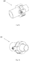
- the coupling mechanism consists of a suitable safety component - in the example of Fig. 1a and Fig. 1b the component is a safety screw 50.
- Each of the connecting elements 10, 20 each has a circular outlet 16, 23 with different diameters. In Fig. 6 and Fig. 7 in the version shown, the diameters differ by about 10%.
- the circular outlets 16, 23 do not have to have the same diameter, since the sealing surfaces surrounding the outlets on both components, together with the elastic seal, ensure the tightness of the connection and the circular outlets 16, 23 are coaxial with the formation of the waterproof, removable connection 100 A-axis lie.
- the first connecting part 10 has at its circular outlet 16 a radially protruding circular edge 11, followed by an axial extension 12 with a base with the length d, the extension 12 having a substantially semicircular cross section and ending in a U-shaped end edge 13 .
- the edge 13 has an inclined wall 17 on the side facing the outlet 16.
- the circular edge 11, the adjoining extension 12 with the lower length d and the end edge 13 together form a receiving space for the insertion and locking of the second connecting part 20.
- a projection 14 is provided with an opening 15 for the safety component 50.
- the second connecting part 20 is provided at its circular opening 23 with a circular, radially outwardly extending flange 21, the thickness h of which is less than the length of the bottom length d of the extension 12.
- the second connecting part 20 is for engagement in the receiving space of the first connecting part 10 suitable.
- the flange 21 of the second connecting part 20 is provided with a recess in which a elastic seal 30 is provided to form a watertight connection.
- the elastic seal 30 extends axially from the flange 21 of the second connection part 20.
- the connecting parts 10, 20 are connected by a transverse displacement between the two parts 10, 20, the second connecting part 20 being moved relative to the first connecting part 10 in the transverse direction F until the second connecting part 20 with its flange 21 touches the extension base 12. This connection is leaking.
- the end edge 13 of the first connecting part 10 enables the second connecting part 20 to be inserted through its U-shaped opening and prevents the second connecting part 20 from being released from the receiving space in the axial direction.
- the wedge connection component 40 is inserted into the space defined by the inclined wall 17 of the end edge 13 and the wall 22 of the flange 21 arranged on the component 20.
- the wall 41 of the key connection part 40 is beveled at the same angle as the inclined wall 17 at the end edge 13.
- connection is sealed in that the wedge connection part 40 is pushed with its wall 41 along the inclined wall 17 arranged on the end edge 13 and the entire wedge connection part 40 is moved in the transverse direction F.
- Fig. 6 the direction of movement F (transverse) and the direction of movement P (axial) in relation to the axis A are shown.
- the opening 15 provided on the projection 14 on the first connecting part 10 for the safety component 50 is below the opening 44 arranged on the extension 43 of the wedge connection part 40 and both openings are coaxial with the axis B.
- the wedge connection part 40 and the First connecting parts 10 can be connected through the openings 14 and 43 through the safety component 50 (in the exemplary embodiment a screw is used as a safety component) in order to prevent the watertight detachable connection 100 from being inadvertently loosened.
- the wedge connection part 40 and the first connection part 10 can also be connected by a further safety component (e.g. two screws, threads, clamp), whereby several holes 15 can be provided on part 10 and the corresponding alignment holes 44 on the wedge connection part 40 .
- a further safety component e.g. two screws, threads, clamp
- the watertight detachable connection 100 is formed by a tight detachable connection of the first connection part 10, the second connection part 20, the elastic seal 30 and the wedge connection part 40.
- the watertight detachable connection 100 can be secured against unintentional loosening by the safety component 50.
- connection mechanism for forming a waterproof detachable connection has wide application, particularly where assembly and disassembly are required in narrow spaces without using installation tools.
- the described invention prevents damage to the elastic seal during assembly or dismantling of the watertight connection and also enables the watertight detachable connection to be additionally secured by a safety component (e.g. clamp, screw, thread) without tools or by means of a suitable tool.
- a safety component e.g. clamp, screw, thread
Landscapes
- Engineering & Computer Science (AREA)
- General Engineering & Computer Science (AREA)
- Power Engineering (AREA)
- Mechanical Engineering (AREA)
- Quick-Acting Or Multi-Walled Pipe Joints (AREA)
- Connector Housings Or Holding Contact Members (AREA)
- Steering Control In Accordance With Driving Conditions (AREA)
- Coupling Device And Connection With Printed Circuit (AREA)
- Seal Device For Vehicle (AREA)
Abstract
Description
- Die Erfindung bezieht sich auf einen Verbindungsmechanismus zur Bildung einer wasserdichten, demontierbaren Verbindung zweier rohrförmiger Komponenten, durch die Flüssigkeit z.B. in einem Hydraulikmodul einer Wasserheizvorrichtung fließt.
- Die Hydraulikmodule in Wasserheizungen enthalten in der Regel eine größere Anzahl von Leitungen mit Anschlussbuchsen, an die weitere Komponenten (z.B. Umwälzpumpe, Ventile, Filter usw.) angeschlossen werden. Die Verbindungen sollen zuverlässig wasserdicht und gleichzeitig im Servicefall lösbar sein.
- Darüber hinaus sollte die Montage und Demontage solcher Verbindungen schnell und selbst bei beengten Platzverhältnissen möglich sein, d.h. in einem Raum, der Monteuren nur eine begrenzte Sicht und einen begrenzten Zugang sowie eine begrenzte Verwendung geeigneter Installationswerkzeuge bietet.
- Verbindungsmechanismen sind nach dem Stand der Technik sowohl für die schnelle Montage als auch für die Demontage von Flüssigkeitsleitungen ohne die Hilfe von Werkzeugen und zusätzlichen Befestigungsmitteln bekannt. Es wird eine Bajonettverbindung verwendet, die durch axiales Einführen der ersten Komponente, die am Ende des ersten Verbundrohrs angeordnet ist, in die zweite Komponente, die am Ende des zweiten Verbundrohrs angeordnet ist, und anschließendes Drehen gebildet wird. Andere Verbindungen werden durch gleichzeitige transversale Bewegung der Befestigungsteile senkrecht zur Verbindungsachse mit oder ohne anschließende Drehung hergestellt.
- Die resultierende Verbindungsqualität wird hauptsächlich durch das Anschlussdesign und die verwendete Dichtung beeinflusst, wobei eines der Hauptprobleme der Dichtungen ihre Haltbarkeit und Zuverlässigkeit ist.
- Der Zweck der Dichtungen in den Anschlüssen, die sich in den Hydraulikmodulen der Wasserheizgeräte befinden, ist es, das Austreten von Flüssigkeit zu verhindern, wenn die Flüssigkeit durch den Anschlussbereich fließt. In den Hydraulikmodulen wird zusätzlich zu den O-Ringen, die zwischen den Endabschnitten des Rohres oder der Flansche oder in die Aussparungen am Ende des Rohres oder des Flansches eingesetzt werden, vorzugsweise die C-Dichtung verwendet.
- Die C-Dichtungen sind elastischer als die O-Ringe, und die C-Dichtungen sind in der Lage, ein ausgezeichnetes Abdichtungsniveau zu erreichen, wenn der Druck der durch sie fließenden Flüssigkeit zunimmt. Ein wichtiges Merkmal der C-Dichtung ist, dass die strömende Flüssigkeit während des Betriebs des Geräts den inneren Hohlraum der Dichtung ausfüllt und durch ihren eigenen Druck eine Dichtkraft erzeugt. Es handelt sich um eine statische Dichtung, und da sie die Teile, die relativ statisch zueinander sind, abdichtet, gibt es während des Betriebs keinen mechanischen Verschleiß der Dichtung. Das elastische Dichtungsmaterial hat die Festigkeit, die C-Form der Dichtung beizubehalten und Radialkräfte, die auf den Kupplungsbereich des Kupplungsmechanismus wirken, wie z.B. Vibrationen, zu absorbieren.
- Das Dokument
US3260539 A offenbart einen Kupplungsverbinder für Flüssigkeitsleitungen, der in Kombination ein Paar komplementärer Kupplungshälften mit sich in Längsrichtung erstreckenden axialen Öffnungen umfasst, die jeweils so angeordnet sind, dass sie mit einer Zufuhrleitung verbunden werden können, wobei jede der Kupplungshälften eine ebene Oberfläche, die sich im Wesentlichen senkrecht zur Achse der Öffnungen erstreckt, einen sich radial erstreckenden bogenförmigen Flansch von im Wesentlichen 180 Grad und einen gegenüberliegenden, sich radial und axial erstreckenden Abschnitt von im Wesentlichen 180 Grad mit einer inneren Aussparung aufweist. Die Kupplungshälften werden durch eine relative Gleitbewegung im wesentlichen senkrecht zur Achse der Öffnungen der Kupplungshälften miteinander verbunden, wobei der Flansch jeder Kupplungshälfte in der Aussparung der anderen Kupplungshälfte aufgenommen wird, wobei sich die Flächen in der Überlappungsposition befinden. Die elastischen Dichtungsmaterialien, wie z.B. ein O-Ring, sind in der Stirnseite einer der Kupplungshälften so angeordnet, dass sie von einer im wesentlichen ebenen Fläche, die sich auf der Stirnseite der anderen Kupplungshälfte befindet, erfasst werden. Der in der Nut befindliche O-Ring ragt normalerweise von der genannten gerillten Oberfläche nach außen. Wenn die Kupplungshälften mit den Oberflächen in einer überlappenden Position zusammengefügt werden, wird der O-Ring durch die ebene Oberfläche zusammengedrückt, um eine undurchlässige Dichtung zwischen den umgebenden Oberflächen der zusammengefügten Kupplungshälften zu bilden. Die montierte Verbindung kann mit einer Schraube gesichert werden. - Das Dokument
US295151 A offenbart eine zweiteilige Schlauchkupplung, die aus einem ersten schwalbenschwanzförmigen Schlitzteil und einem in einer Schlitzaussparung untergebrachten Dichtungsring besteht, in Kombination mit einem zweiten schwalbenschwanzförmigen Teil, der so positioniert ist, dass er vollständig in den Schwalbenschwanzschlitz eingreift und den Dichtungsring drückt. - Das Dokument
EP3139078 A1 offenbart eine Erfindung eines Kopplungsmechanismus, der aus zwei identischen Komponenten besteht, die aus Aufnahme- und Eingriffselementen bestehen. Um die Kupplungselemente miteinander zu verbinden, erfordert der Kupplungsmechanismus der vorliegenden Erfindung eine relative Verschiebung, insbesondere eine translatorische Bewegung, der Kupplungsteile zueinander in einer im wesentlichen radialen Richtung. Sobald ein Bauteil in das andere Bauteil eingesetzt wird, ist die Verbindung gegen Verschiebung in axialer Richtung gesichert. Versehentliche Verschiebungen in der radialen Richtung, mit der die Elemente miteinander verbunden wurden, können zusätzlich verhindert werden, z.B. durch Verschraubung. Die halbkreisförmige Geometrie der Aufnahme- und Eingriffselemente ermöglicht eine platzsparende und allgemein effiziente Konstruktion, die ein gleitendes Eingreifen der Elemente erleichtert. In den exemplarischen Ausführungsformen werden Dichtungsformen wie Beschichtung, Klebematerial oder spezielle Dichtungselemente verwendet. Die C-Dichtung scheint die bevorzugte Lösung zu sein. Die Form der C-Dichtung stellt sicher, dass sich die Dichtung nach dem Herstellen der Verbindung nicht versehentlich aus dem Mechanismus löst. Eine solche Dichtung ist auf lange Sicht sehr zuverlässig. - Alle oben genannten Lösungen sind dadurch gekennzeichnet, dass die translatorische Bewegung der Kupplungskomponenten relativ zueinander in einer im Wesentlichen radialen Richtung erforderlich ist, um die Kupplungskomponenten miteinander zu verbinden. Gleichzeitig ist nach der translatorischen Kopplung der Komponenten keine weitere Befestigung der Verbindung in axialer Richtung erforderlich. Der Nachteil dieser Lösungen ist die höhere Wahrscheinlichkeit, dass die elastische Dichtung beschädigt wird, insbesondere wenn sie vorsteht und den Weg einer solchen Translationsbewegung stört. Tests ähnlicher Lösungen haben gezeigt, dass sich insbesondere die C-Dichtung aus weichem, elastischem Material verformt, was unerwünscht ist. Dieser Nachteil wird durch die offengelegte Erfindung beseitigt.
- Der Verbindungsmechanismus zur Bildung einer wasserdichten lösbaren Verbindung nach dieser Erfindung besteht aus zwei verschiedenen Verbindungsteilen, wobei das erste Verbindungsteil mit einem Aufnahmeraum für das zweite Verbindungsteil versehen ist und das zweite Verbindungsteil in den Aufnahmeraum des ersten Verbindungsteils eingreifen kann, wobei beide Verbindungsteile einen entsprechenden komplementären Auslass haben. Außerdem besteht der Verbindungsmechanismus aus einer elastischen Dichtung, die an der zweiten Verbindungskomponente angebracht ist und sich axial von dieser zweiten Verbindungskomponente aus erstreckt. Der Verbindungsmechanismus besteht ferner aus einem Keilverbindungsteil. Beim Einsetzen des Keilverbindungsbauteils in den vorgesehenen Raum wird eine wasserdichte Verbindung gebildet, so dass die die Auslässe beider Bauteile umgebenden Dichtflächen und die elastische Dichtung in engen Kontakt kommen. Die wasserdichte demontierbare Verbindung kann vorteilhaft durch ein geeignetes Sicherheitselement (z.B. durch Schraube, Niete oder Klammer) gesichert werden. Die erste und zweite Verbindungskomponente werden an den Enden der zu verbindenden Rohrleitung oder an den Enden der Hydraulikmodulkomponenten auf jede bekannte Weise befestigt (z.B. durch Schweißen, Kleben, Schrauben oder Bajonettverschluss) oder die erste und zweite Verbindungskomponente können zusammen mit der Hydraulikmodulkomponente aus einem Werkzeug gegossen werden (z.B. als Teil einer Kunststoffabdeckung einer Umwälzpumpe). Die erste und die zweite Verbindungskomponente haben jeweils einen kreisförmigen Auslass, diese Auslässe dürfen nicht den gleichen Durchmesser haben, und diese Auslässe sind nach der Bildung der wasserdichten, demontierbaren Verbindung koaxial.
- Unter einer wasserdichten demontierbaren Verbindung im Sinne dieser Erfindung ist die Verbindung eines Rohres und eines Hydraulikmodulbauteils oder zweier Rohre oder die Verbindung zweier Bauteile eines Hydraulikmoduls mittels des beschriebenen Kupplungsmechanismus oder auch eine durch einen Kupplungsmechanismus gebildete Verbindung zu verstehen.
- Die Erfindung wird in Zeichnungen näher erläutert, ist aber nicht auf diese beschränkt.
-
Abb. 1a und Abb. 1b zeigen eine wasserdichte, demontierbare Verbindung, die durch einen mit einem Sicherheitsbauteil versehenen Verbindungsmechanismus gebildet wird, in zwei unterschiedlich gedrehten Perspektivansichten -
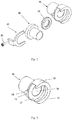
Abb. 2 zeigt die einzelnen Komponenten des Verbindungsmechanismus - erstes Verbindungselement, zweites Verbindungselement, elastische Dichtung, Keilverbindungselement und ein optionales Sicherheitselement. -
Abb. 3 zeigt eine räumliche Darstellung eines ersten Verbindungsteils, das mit einem Aufnahmeraum für ein zweites Verbindungsteil versehen ist -
Abb. 4 zeigt eine räumliche Darstellung eines zweiten Verbindungsteils, das sich mit seinem Flansch in den Aufnahmeraum des ersten Verbindungsteils einführen und einrasten lässt -
Abb. 5 zeigt einen Querschnitt eines ersten Verbindungsbauteils mit Angaben zum Aufnahmeraum -
Abb. 6 zeigt schematisch einen Querschnitt einer undichten Verbindung des ersten und zweiten Verbindungsteils und einen Querschnitt eines Keilverbindungsteils -
Abb. 7 zeigt schematisch den Querschnitt einer wasserdichten lösbaren Verbindung, die aus Komponenten eines Verbindungsmechanismus ohne Sicherheitsbauteil gebildet wird. - Der Verbindungsmechanismus zur Bildung der wasserdichten demontierbaren Verbindung 100 umfasst ein erstes Verbindungsteil 10, das mit einem Aufnahmeraum versehen ist, ein zweites Verbindungsteil 20, das mit einem Flansch 21 zum Eingriff in den Aufnahmeraum des ersten Verbindungsteils 10 und mit einer Aussparung im Flansch 21 für die elastische Dichtung 30 und dem Keilverbindungsteil 40 versehen ist. In einer bevorzugten Ausführung besteht der Kupplungsmechanismus aus einem geeigneten Sicherheitsbauteil - im Beispiel von
Abb. 1a und Abb. 1b ist das Bauteil eine Sicherheitsschraube 50. - Jedes der Verbindungselemente 10, 20 hat jeweils einen kreisförmigen Auslass 16, 23 mit unterschiedlichen Durchmessern. In
Abb. 6 undAbb. 7 in der abgebildeten Ausführung unterscheiden sich die Durchmesser um etwa 10%. Die kreisförmigen Auslässe 16, 23 müssen nicht den gleichen Durchmesser haben, da die die Auslässe an beiden Bauteilen umgebenden Dichtflächen zusammen mit der elastischen Dichtung für die Dichtheit der Verbindung sorgen und die kreisförmigen Auslässe 16, 23 bei der Bildung des wasserdichten demontierbaren Anschlusses 100 koaxial zur A-Achse liegen. - Das erste Verbindungsteil 10 hat an seinem kreisförmigen Auslass 16 einen radial vorstehenden kreisförmigen Rand 11, gefolgt von einem axialen Fortsatz 12 mit einem Boden mit der Länge d, wobei der Fortsatz 12 einen im Wesentlichen halbkreisförmigen Querschnitt hat und in einem U-förmigen Endrand 13 endet. Der Rand 13 hat auf der dem Auslass 16 zugewandten Seite eine schräge Wand 17.
- Der kreisrunde Rand 11, der angrenzende Fortsatz 12 mit der unteren Länge d und der Endrand 13 bilden zusammen einen Aufnahmeraum für das Einsetzen und Einrasten des zweiten Verbindungsteils 20.
- Auf der Seite des Randes 11, die vom Boden der Verlängerung 12 und gleichzeitig von der den Auslass 16 des Bauteils 10 umgebenden Dichtfläche abgewandt ist, ist ein Vorsprung 14 mit einer Öffnung 15 für das Sicherheitsbauteil 50 versehen.
- Das zweite Verbindungsteil 20 ist an seiner kreisförmigen Öffnung 23 mit einem kreisförmigen, sich radial nach außen erstreckenden Flansch 21 versehen, dessen Dicke h geringer ist als die Länge der Bodenlänge d der Verlängerung 12. Das zweite Verbindungsteil 20 ist für den Eingriff in den Aufnahmeraum des ersten Verbindungsteils 10 geeignet. Der Flansch 21 des zweiten Verbindungsteils 20 ist mit einer Aussparung versehen, in der eine elastische Dichtung 30 zur Bildung einer wasserdichten Verbindung vorgesehen ist. Die elastische Dichtung 30 erstreckt sich axial vom Flansch 21 des zweiten Anschlussteils 20.
- Die Verbindung der Verbindungsteile 10, 20 erfolgt durch eine Querverschiebung zwischen den beiden Teilen 10, 20, wobei das zweite Verbindungsteil 20 relativ zum ersten Verbindungsteil 10 in Querrichtung F bewegt wird, bis das zweite Verbindungsteil 20 mit seinem Flansch 21 den Verlängerungsboden 12 berührt. Diese Verbindung ist undicht.
- Der Endrand 13 des ersten Verbindungsteils 10 ermöglicht das Einführen des zweiten Verbindungsteils 20 durch seine U-förmige Öffnung und verhindert das Lösen des zweiten Verbindungsteils 20 aus dem Aufnahmeraum in axialer Richtung.
- Nach der undichten Verbindung der Bauteile 10, 20 wird das Keilverbindungsbauteil 40 in den durch die schräge Wand 17 des Endrandes 13 und die Wand 22 des auf dem Bauteil 20 angeordneten Flansches 21 definierten Raum eingesetzt. Die Wand 41 des Keilverbindungsteils 40 ist im gleichen Winkel wie die schräge Wand 17 am Endrand 13 abgeschrägt.
- Die Abdichtung der Verbindung wird erreicht, indem das Keilverbindungsteil 40 mit seiner Wand 41 entlang der schrägen, am Stirnrand 13 angeordneten Wand 17 geschoben wird und das gesamte Keilverbindungsteil 40 in Querrichtung F bewegt wird.
- Bei der Schiebebewegung des Keilverbindungsbauteils 40 in Querrichtung F wird die am Keilverbindungsbauteil 40 angeordnete gerade Wand 42 gegen die am Flansch 21 des zweiten Verbindungsbauteils 20 angeordnete Wand 22 gedrückt. Durch die beschriebene Bewegung des Keilverbindungsteils 40 wird das zweite Verbindungsteil 20 gegen das erste Verbindungsteil 10 in axialer Richtung P gedrückt. Gleichzeitig kommt die elastische Dichtung 30 ohne Verformungsreibung in engen Kontakt mit den Ausgängen 16, 23 der beiden Teile 10, 20.
- In
Abb. 6 ist die Bewegungsrichtung F (transversal) und die Bewegungsrichtung P (axial) in Bezug auf die Achse A dargestellt. - Nach Bildung der wasserdichten lösbaren Verbindung 100 befindet sich die am Vorsprung 14 am ersten Verbindungsteil 10 vorgesehene Öffnung 15 für das Sicherheitsbauteil 50 unterhalb der auf der Verlängerung 43 des Keilverbindungsteils 40 angeordneten Öffnung 44 und beide Öffnungen sind koaxial zur Achse B. Das Keilverbindungsteil 40 und das erste Verbindungsteil 10 können durch die Öffnungen 14 und 43 durch das Sicherheitsbauteil 50 verbunden werden (in der Beispielausführung wird eine Schraube als Sicherheitsbauteil verwendet), um ein unbeabsichtigtes Lösen der wasserdichten lösbaren Verbindung 100 zu verhindern.
- Es wird davon ausgegangen, dass das Keilverbindungsteil 40 und das erste Verbindungsteil 10 auch durch ein weiteres Sicherheitsbauteil (z.B. zwei Schrauben, Gewinde, Schelle) verbunden werden können, wobei mehrere Löcher 15 am Teil 10 und die entsprechenden Ausrichtungslöcher 44 am Keilverbindungsteil 40 vorgesehen werden können.
- Die wasserdichte demontierbare Verbindung 100 wird durch eine dichte lösbare Verbindung des ersten Verbindungsteils 10, des zweiten Verbindungsteils 20, der elastischen Dichtung 30 und des Keilverbindungsteils 40 gebildet. Die wasserdichte demontierbare Verbindung 100 kann durch das Sicherheitsbauteil 50 gegen unbeabsichtigtes Lösen gesichert werden.
- Der Verbindungsmechanismus zur Bildung einer wasserdichten, demontierbaren Verbindung nach der vorliegenden Erfindung hat eine breite Anwendung, insbesondere dort, wo die Montage und Demontage in engen Räumen ohne Verwendung von Installationswerkzeugen erforderlich ist. Die beschriebene Erfindung verhindert eine Beschädigung der elastischen Dichtung bei der Montage oder Demontage der wasserdichten Verbindung und ermöglicht darüber hinaus eine zusätzliche Sicherung der wasserdichten demontierbaren Verbindung durch ein Sicherheitsbauteil (z.B. Schelle, Schraube, Gewinde) ohne Werkzeug oder mittels eines geeigneten Werkzeugs.
-
- 100
- wasserdichte, demontierbare Verbindung
- 10
- erstes Verbindungselement
- 20
- Sekunden Anschlusskomponente
- 30
- elastische Dichtung
- 40
- Keilverbindungselement
- 50
- Sicherheitskomponente
- 11
- kreisförmiger Rand
- 12
- Verlängerung
- 13
- Endrand
- 14
- Projektion
- 15
- Öffnung
- 16
- runde Auslassöffnungen
- 17
- schräge Wand
- 21
- Flansch
- 22
- Wand
- 23
- runder Auslass
- 41
- Schräge Wand
- 42
- gerade Wand
- 43
- Verlängerung
- 44
- Öffnung
- A
- B-Axt
- d
- Bodenlänge
- h
- Flanschdicke
- P
- axiale Richtung
- F
- Querrichtung
Claims (6)
- Verbindungsmechanismus zur Bildung einer wasserdichten, demontierbaren Verbindung, umfassend ein erstes Verbindungselement, das mit einem Aufnahmeraum versehen ist, ein zweites Verbindungselement zum Eingriff in den Aufnahmeraum des ersten Verbindungselements, eine elastische Dichtung und ein Keilverbindungselement, dadurch gekennzeichnet, dass das erste Verbindungselement (10) an seinem kreisförmigen Auslass (16) mit einem radial vorstehenden kreisförmigen Rand (11) mit einer anschließenden axialen Verlängerung (12) von im wesentlichen halbkreisförmigem Querschnitt versehen ist, dessen Boden mit der Länge von (d) durch einen Endrand (13) mit U-förmigem Querschnitt begrenzt ist und an dem Endrand (13) zum Auslass (16) hin eine schräge Wand (17) angeordnet ist, das zweite Verbindungsteil (20) an seinem kreisförmigen Auslass (23) mit einem kreisförmigen, radial nach außen vorstehenden Flansch (21) versehen ist und seine Dicke (h) geringer ist als die Länge (d) des Bodens der Verlängerung (12), der Flansch (21) mit einer elastischen Dichtung (30) versehen ist und das Keilverbindungsteil (40) mit einer schrägen Wand (41) versehen ist, die in einem Winkel abgewinkelt ist, der mit dem Neigungswinkel der am Endrand (13) angeordneten Wand (17) übereinstimmt.
- Verbindungsmechanismus von Anspruch 1, dadurch gekennzeichnet, dass die elastische Dichtung (30) ein O-Ring ist.
- Verbindungsmechanismus von Anspruch 1, dadurch gekennzeichnet, dass die elastische Dichtung (30) eine C-Dichtung ist.
- Verbindungsmechanismus gemäß einem der vorhergehenden Ansprüche,dadurch gekennzeichnet, dass am ersten Verbindungselement (10) auf der vom Boden der Verlängerung (12) abgewandten Seite des kreisförmigen Randes (11) und gleichzeitig von der seinen kreisförmigen Auslass (16) umgebenden Dichtfläche abgewandt, ist der Vorsprung (14) mit mindestens einer Öffnung (15) für das Sicherheitselement (50) versehen und an dem Keilbeschlag (40) ist eine mit mindestens einer Öffnung (44) für das Sicherheitsbauteil (50) versehene Verlängerung (43) angeordnet.
- Verbindungsmechanismus von Anspruch 4, gekennzeichnet, dass das erste Verbindungselement (10), das zweite Verbindungselement (20), die elastische Dichtung (30) und das Keilverbindungselement (40) mit der demontierbaren wasserdichten Verbindung (100) verbunden sind und die Öffnungen (15, 44) für das Sicherheitselement durch das Sicherheitselement (50) miteinander verbunden sind.
- Der Verbindungsmechanismus von Anspruch 5, dadurch gekennzeichnet, dass das Sicherheitsbauteil (50) eines der Elemente Schraube, Niet, Klemme ist.
Applications Claiming Priority (1)
| Application Number | Priority Date | Filing Date | Title |
|---|---|---|---|
| SK122019U SK8633Y1 (sk) | 2019-02-14 | 2019-02-14 | Spojovací mechanizmus |
Publications (2)
| Publication Number | Publication Date |
|---|---|
| EP3696458A1 true EP3696458A1 (de) | 2020-08-19 |
| EP3696458B1 EP3696458B1 (de) | 2022-11-23 |
Family
ID=66999498
Family Applications (1)
| Application Number | Title | Priority Date | Filing Date |
|---|---|---|---|
| EP20156077.8A Active EP3696458B1 (de) | 2019-02-14 | 2020-02-07 | Verbindungsmechanismus |
Country Status (3)
| Country | Link |
|---|---|
| EP (1) | EP3696458B1 (de) |
| ES (1) | ES2937393T3 (de) |
| SK (1) | SK8633Y1 (de) |
Cited By (1)
| Publication number | Priority date | Publication date | Assignee | Title |
|---|---|---|---|---|
| EP4283175A1 (de) * | 2022-05-24 | 2023-11-29 | Funke Kunststoffe GmbH | Rohrleitungskupplung |
Citations (4)
| Publication number | Priority date | Publication date | Assignee | Title |
|---|---|---|---|---|
| US295151A (en) | 1883-07-27 | 1884-03-18 | James cummin s | |
| US760424A (en) * | 1903-05-20 | 1904-05-24 | Edward Jewell | Pipe-coupling. |
| US3260539A (en) | 1965-02-10 | 1966-07-12 | Donald E Herron | Coupling for fluid conduits |
| EP3139078A1 (de) | 2015-09-01 | 2017-03-08 | Gealan Formteile GmbH | Verbindungsmechanismus für hydrauliksysteme |
-
2019
- 2019-02-14 SK SK122019U patent/SK8633Y1/sk unknown
-
2020
- 2020-02-07 EP EP20156077.8A patent/EP3696458B1/de active Active
- 2020-02-07 ES ES20156077T patent/ES2937393T3/es active Active
Patent Citations (4)
| Publication number | Priority date | Publication date | Assignee | Title |
|---|---|---|---|---|
| US295151A (en) | 1883-07-27 | 1884-03-18 | James cummin s | |
| US760424A (en) * | 1903-05-20 | 1904-05-24 | Edward Jewell | Pipe-coupling. |
| US3260539A (en) | 1965-02-10 | 1966-07-12 | Donald E Herron | Coupling for fluid conduits |
| EP3139078A1 (de) | 2015-09-01 | 2017-03-08 | Gealan Formteile GmbH | Verbindungsmechanismus für hydrauliksysteme |
Cited By (1)
| Publication number | Priority date | Publication date | Assignee | Title |
|---|---|---|---|---|
| EP4283175A1 (de) * | 2022-05-24 | 2023-11-29 | Funke Kunststoffe GmbH | Rohrleitungskupplung |
Also Published As
| Publication number | Publication date |
|---|---|
| SK8633Y1 (sk) | 2019-12-02 |
| ES2937393T3 (es) | 2023-03-28 |
| EP3696458B1 (de) | 2022-11-23 |
| SK122019U1 (sk) | 2019-07-02 |
Similar Documents
| Publication | Publication Date | Title |
|---|---|---|
| DE68903722T2 (de) | Aus segmenten aufgebaute rohrverbinder. | |
| DE69708480T2 (de) | Rohrverbindung | |
| DE69713447T2 (de) | Rohrverbindungsvorrichtung mit Zapfen- und Muffen-Teilen die entsprechende kegelstumpfförmige Flächen aufweisen | |
| DE102010013412B4 (de) | Abgasleitung für ein Kraftfahrzeug und Abgasanlage | |
| DE69101596T2 (de) | Rohrkupplung. | |
| DE2058203C2 (de) | Rohrverbinder | |
| DE4001275A1 (de) | Zwischen einer metallrohrleitung geringen durchmessers und einem flexiblen schlauch eingebrachter konnektor | |
| DE2701873B2 (de) | Schnellkupplung für Kunstharzrohre | |
| DE2135481A1 (de) | Kompressionskupplung fur Rohrleitungen | |
| DE4205539A1 (de) | Zentralheizungsanlage und rohrkupplung hierfuer | |
| DE3340899A1 (de) | Vorrichtung zum verbinden zweier rohrenden | |
| DE69407777T2 (de) | Kuppelstück | |
| WO2015135812A1 (de) | Kupplung für rohrelemente | |
| DE102009036463A1 (de) | Kopplungsbaugruppe für eine Fahrzeug-Klimaanlage | |
| DE1525454C3 (de) | Rohr- oder schlauchkupplung | |
| EP3696458B1 (de) | Verbindungsmechanismus | |
| EP3746692B1 (de) | Wasserleitung mit rohrfitting | |
| DE2610878A1 (de) | Rohrverbindung mit einer schraubmuffe | |
| DE202010011501U1 (de) | Dichtsystem, Dichtkörper sowie Klemmkörper für selbiges | |
| DE10152975C1 (de) | Pressfitting für den Anschluss mindestens eines Rohres | |
| DE102006005259A1 (de) | Verbesserte Druckverbindung für Rohre | |
| DE3104518A1 (de) | Anschlussarmatur | |
| EP3230648B1 (de) | Vorgefertigte ventil-baueinheit, montageverfahren zur montage der ventil-baueinheit, aufnahmeteil einer mit der ventil-baueinheit ausgestatteten fluid-trockenkupplung sowie das aufnahmeteil aufweisende fluid-trockenkupplung | |
| WO2020119966A1 (de) | Dichtungsanordnung für ein geteiltes gehäuse | |
| DE29901351U1 (de) | Verstellbarer Keilring |
Legal Events
| Date | Code | Title | Description |
|---|---|---|---|
| PUAI | Public reference made under article 153(3) epc to a published international application that has entered the european phase |
Free format text: ORIGINAL CODE: 0009012 |
|
| STAA | Information on the status of an ep patent application or granted ep patent |
Free format text: STATUS: THE APPLICATION HAS BEEN PUBLISHED |
|
| AK | Designated contracting states |
Kind code of ref document: A1 Designated state(s): AL AT BE BG CH CY CZ DE DK EE ES FI FR GB GR HR HU IE IS IT LI LT LU LV MC MK MT NL NO PL PT RO RS SE SI SK SM TR |
|
| AX | Request for extension of the european patent |
Extension state: BA ME |
|
| STAA | Information on the status of an ep patent application or granted ep patent |
Free format text: STATUS: REQUEST FOR EXAMINATION WAS MADE |
|
| 17P | Request for examination filed |
Effective date: 20210216 |
|
| RBV | Designated contracting states (corrected) |
Designated state(s): AL AT BE BG CH CY CZ DE DK EE ES FI FR GB GR HR HU IE IS IT LI LT LU LV MC MK MT NL NO PL PT RO RS SE SI SK SM TR |
|
| GRAP | Despatch of communication of intention to grant a patent |
Free format text: ORIGINAL CODE: EPIDOSNIGR1 |
|
| STAA | Information on the status of an ep patent application or granted ep patent |
Free format text: STATUS: GRANT OF PATENT IS INTENDED |
|
| INTG | Intention to grant announced |
Effective date: 20220615 |
|
| GRAS | Grant fee paid |
Free format text: ORIGINAL CODE: EPIDOSNIGR3 |
|
| GRAA | (expected) grant |
Free format text: ORIGINAL CODE: 0009210 |
|
| STAA | Information on the status of an ep patent application or granted ep patent |
Free format text: STATUS: THE PATENT HAS BEEN GRANTED |
|
| AK | Designated contracting states |
Kind code of ref document: B1 Designated state(s): AL AT BE BG CH CY CZ DE DK EE ES FI FR GB GR HR HU IE IS IT LI LT LU LV MC MK MT NL NO PL PT RO RS SE SI SK SM TR |
|
| REG | Reference to a national code |
Ref country code: GB Ref legal event code: FG4D Free format text: NOT ENGLISH |
|
| REG | Reference to a national code |
Ref country code: CH Ref legal event code: EP |
|
| REG | Reference to a national code |
Ref country code: AT Ref legal event code: REF Ref document number: 1533321 Country of ref document: AT Kind code of ref document: T Effective date: 20221215 Ref country code: DE Ref legal event code: R096 Ref document number: 502020002028 Country of ref document: DE |
|
| REG | Reference to a national code |
Ref country code: IE Ref legal event code: FG4D Free format text: LANGUAGE OF EP DOCUMENT: GERMAN |
|
| REG | Reference to a national code |
Ref country code: LT Ref legal event code: MG9D |
|
| REG | Reference to a national code |
Ref country code: ES Ref legal event code: FG2A Ref document number: 2937393 Country of ref document: ES Kind code of ref document: T3 Effective date: 20230328 |
|
| REG | Reference to a national code |
Ref country code: NL Ref legal event code: MP Effective date: 20221123 |
|
| PG25 | Lapsed in a contracting state [announced via postgrant information from national office to epo] |
Ref country code: SE Free format text: LAPSE BECAUSE OF FAILURE TO SUBMIT A TRANSLATION OF THE DESCRIPTION OR TO PAY THE FEE WITHIN THE PRESCRIBED TIME-LIMIT Effective date: 20221123 Ref country code: PT Free format text: LAPSE BECAUSE OF FAILURE TO SUBMIT A TRANSLATION OF THE DESCRIPTION OR TO PAY THE FEE WITHIN THE PRESCRIBED TIME-LIMIT Effective date: 20230323 Ref country code: NO Free format text: LAPSE BECAUSE OF FAILURE TO SUBMIT A TRANSLATION OF THE DESCRIPTION OR TO PAY THE FEE WITHIN THE PRESCRIBED TIME-LIMIT Effective date: 20230223 Ref country code: LT Free format text: LAPSE BECAUSE OF FAILURE TO SUBMIT A TRANSLATION OF THE DESCRIPTION OR TO PAY THE FEE WITHIN THE PRESCRIBED TIME-LIMIT Effective date: 20221123 Ref country code: FI Free format text: LAPSE BECAUSE OF FAILURE TO SUBMIT A TRANSLATION OF THE DESCRIPTION OR TO PAY THE FEE WITHIN THE PRESCRIBED TIME-LIMIT Effective date: 20221123 |
|
| PG25 | Lapsed in a contracting state [announced via postgrant information from national office to epo] |
Ref country code: RS Free format text: LAPSE BECAUSE OF FAILURE TO SUBMIT A TRANSLATION OF THE DESCRIPTION OR TO PAY THE FEE WITHIN THE PRESCRIBED TIME-LIMIT Effective date: 20221123 Ref country code: PL Free format text: LAPSE BECAUSE OF FAILURE TO SUBMIT A TRANSLATION OF THE DESCRIPTION OR TO PAY THE FEE WITHIN THE PRESCRIBED TIME-LIMIT Effective date: 20221123 Ref country code: LV Free format text: LAPSE BECAUSE OF FAILURE TO SUBMIT A TRANSLATION OF THE DESCRIPTION OR TO PAY THE FEE WITHIN THE PRESCRIBED TIME-LIMIT Effective date: 20221123 Ref country code: IS Free format text: LAPSE BECAUSE OF FAILURE TO SUBMIT A TRANSLATION OF THE DESCRIPTION OR TO PAY THE FEE WITHIN THE PRESCRIBED TIME-LIMIT Effective date: 20230323 Ref country code: HR Free format text: LAPSE BECAUSE OF FAILURE TO SUBMIT A TRANSLATION OF THE DESCRIPTION OR TO PAY THE FEE WITHIN THE PRESCRIBED TIME-LIMIT Effective date: 20221123 Ref country code: GR Free format text: LAPSE BECAUSE OF FAILURE TO SUBMIT A TRANSLATION OF THE DESCRIPTION OR TO PAY THE FEE WITHIN THE PRESCRIBED TIME-LIMIT Effective date: 20230224 |
|
| PG25 | Lapsed in a contracting state [announced via postgrant information from national office to epo] |
Ref country code: NL Free format text: LAPSE BECAUSE OF FAILURE TO SUBMIT A TRANSLATION OF THE DESCRIPTION OR TO PAY THE FEE WITHIN THE PRESCRIBED TIME-LIMIT Effective date: 20221123 |
|
| PG25 | Lapsed in a contracting state [announced via postgrant information from national office to epo] |
Ref country code: SM Free format text: LAPSE BECAUSE OF FAILURE TO SUBMIT A TRANSLATION OF THE DESCRIPTION OR TO PAY THE FEE WITHIN THE PRESCRIBED TIME-LIMIT Effective date: 20221123 Ref country code: RO Free format text: LAPSE BECAUSE OF FAILURE TO SUBMIT A TRANSLATION OF THE DESCRIPTION OR TO PAY THE FEE WITHIN THE PRESCRIBED TIME-LIMIT Effective date: 20221123 Ref country code: EE Free format text: LAPSE BECAUSE OF FAILURE TO SUBMIT A TRANSLATION OF THE DESCRIPTION OR TO PAY THE FEE WITHIN THE PRESCRIBED TIME-LIMIT Effective date: 20221123 Ref country code: DK Free format text: LAPSE BECAUSE OF FAILURE TO SUBMIT A TRANSLATION OF THE DESCRIPTION OR TO PAY THE FEE WITHIN THE PRESCRIBED TIME-LIMIT Effective date: 20221123 Ref country code: CZ Free format text: LAPSE BECAUSE OF FAILURE TO SUBMIT A TRANSLATION OF THE DESCRIPTION OR TO PAY THE FEE WITHIN THE PRESCRIBED TIME-LIMIT Effective date: 20221123 |
|
| REG | Reference to a national code |
Ref country code: DE Ref legal event code: R097 Ref document number: 502020002028 Country of ref document: DE |
|
| PG25 | Lapsed in a contracting state [announced via postgrant information from national office to epo] |
Ref country code: SK Free format text: LAPSE BECAUSE OF FAILURE TO SUBMIT A TRANSLATION OF THE DESCRIPTION OR TO PAY THE FEE WITHIN THE PRESCRIBED TIME-LIMIT Effective date: 20221123 Ref country code: AL Free format text: LAPSE BECAUSE OF FAILURE TO SUBMIT A TRANSLATION OF THE DESCRIPTION OR TO PAY THE FEE WITHIN THE PRESCRIBED TIME-LIMIT Effective date: 20221123 |
|
| PG25 | Lapsed in a contracting state [announced via postgrant information from national office to epo] |
Ref country code: MC Free format text: LAPSE BECAUSE OF FAILURE TO SUBMIT A TRANSLATION OF THE DESCRIPTION OR TO PAY THE FEE WITHIN THE PRESCRIBED TIME-LIMIT Effective date: 20221123 |
|
| PLBE | No opposition filed within time limit |
Free format text: ORIGINAL CODE: 0009261 |
|
| REG | Reference to a national code |
Ref country code: CH Ref legal event code: PL |
|
| STAA | Information on the status of an ep patent application or granted ep patent |
Free format text: STATUS: NO OPPOSITION FILED WITHIN TIME LIMIT |
|
| REG | Reference to a national code |
Ref country code: BE Ref legal event code: MM Effective date: 20230228 |
|
| PG25 | Lapsed in a contracting state [announced via postgrant information from national office to epo] |
Ref country code: LU Free format text: LAPSE BECAUSE OF NON-PAYMENT OF DUE FEES Effective date: 20230207 Ref country code: LI Free format text: LAPSE BECAUSE OF NON-PAYMENT OF DUE FEES Effective date: 20230228 Ref country code: CH Free format text: LAPSE BECAUSE OF NON-PAYMENT OF DUE FEES Effective date: 20230228 |
|
| 26N | No opposition filed |
Effective date: 20230824 |
|
| PG25 | Lapsed in a contracting state [announced via postgrant information from national office to epo] |
Ref country code: SI Free format text: LAPSE BECAUSE OF FAILURE TO SUBMIT A TRANSLATION OF THE DESCRIPTION OR TO PAY THE FEE WITHIN THE PRESCRIBED TIME-LIMIT Effective date: 20221123 |
|
| REG | Reference to a national code |
Ref country code: IE Ref legal event code: MM4A |
|
| PG25 | Lapsed in a contracting state [announced via postgrant information from national office to epo] |
Ref country code: IE Free format text: LAPSE BECAUSE OF NON-PAYMENT OF DUE FEES Effective date: 20230207 |
|
| PG25 | Lapsed in a contracting state [announced via postgrant information from national office to epo] |
Ref country code: BE Free format text: LAPSE BECAUSE OF NON-PAYMENT OF DUE FEES Effective date: 20230228 |
|
| PGFP | Annual fee paid to national office [announced via postgrant information from national office to epo] |
Ref country code: ES Payment date: 20240301 Year of fee payment: 5 |
|
| PGFP | Annual fee paid to national office [announced via postgrant information from national office to epo] |
Ref country code: DE Payment date: 20240201 Year of fee payment: 5 Ref country code: GB Payment date: 20240129 Year of fee payment: 5 |
|
| PGFP | Annual fee paid to national office [announced via postgrant information from national office to epo] |
Ref country code: IT Payment date: 20240227 Year of fee payment: 5 Ref country code: FR Payment date: 20240227 Year of fee payment: 5 |
|
| PG25 | Lapsed in a contracting state [announced via postgrant information from national office to epo] |
Ref country code: BG Free format text: LAPSE BECAUSE OF FAILURE TO SUBMIT A TRANSLATION OF THE DESCRIPTION OR TO PAY THE FEE WITHIN THE PRESCRIBED TIME-LIMIT Effective date: 20221123 |
|
| PG25 | Lapsed in a contracting state [announced via postgrant information from national office to epo] |
Ref country code: BG Free format text: LAPSE BECAUSE OF FAILURE TO SUBMIT A TRANSLATION OF THE DESCRIPTION OR TO PAY THE FEE WITHIN THE PRESCRIBED TIME-LIMIT Effective date: 20221123 |
|
| PGFP | Annual fee paid to national office [announced via postgrant information from national office to epo] |
Ref country code: AT Payment date: 20250417 Year of fee payment: 5 |
|
| PG25 | Lapsed in a contracting state [announced via postgrant information from national office to epo] |
Ref country code: CY Free format text: LAPSE BECAUSE OF FAILURE TO SUBMIT A TRANSLATION OF THE DESCRIPTION OR TO PAY THE FEE WITHIN THE PRESCRIBED TIME-LIMIT; INVALID AB INITIO Effective date: 20200207 |
|
| PG25 | Lapsed in a contracting state [announced via postgrant information from national office to epo] |
Ref country code: HU Free format text: LAPSE BECAUSE OF FAILURE TO SUBMIT A TRANSLATION OF THE DESCRIPTION OR TO PAY THE FEE WITHIN THE PRESCRIBED TIME-LIMIT; INVALID AB INITIO Effective date: 20200207 |
|
| REG | Reference to a national code |
Ref country code: DE Ref legal event code: R119 Ref document number: 502020002028 Country of ref document: DE |
|
| GBPC | Gb: european patent ceased through non-payment of renewal fee |
Effective date: 20250207 |
|
| PG25 | Lapsed in a contracting state [announced via postgrant information from national office to epo] |
Ref country code: TR Free format text: LAPSE BECAUSE OF FAILURE TO SUBMIT A TRANSLATION OF THE DESCRIPTION OR TO PAY THE FEE WITHIN THE PRESCRIBED TIME-LIMIT Effective date: 20221123 |
|
| PG25 | Lapsed in a contracting state [announced via postgrant information from national office to epo] |
Ref country code: DE Free format text: LAPSE BECAUSE OF NON-PAYMENT OF DUE FEES Effective date: 20250902 |
|
| PG25 | Lapsed in a contracting state [announced via postgrant information from national office to epo] |
Ref country code: GB Free format text: LAPSE BECAUSE OF NON-PAYMENT OF DUE FEES Effective date: 20250207 |
|
| PG25 | Lapsed in a contracting state [announced via postgrant information from national office to epo] |
Ref country code: FR Free format text: LAPSE BECAUSE OF NON-PAYMENT OF DUE FEES Effective date: 20250228 Ref country code: IT Free format text: LAPSE BECAUSE OF NON-PAYMENT OF DUE FEES Effective date: 20250207 |
|
| REG | Reference to a national code |
Ref country code: ES Ref legal event code: FD2A Effective date: 20260326 |
|
| PG25 | Lapsed in a contracting state [announced via postgrant information from national office to epo] |
Ref country code: ES Free format text: LAPSE BECAUSE OF NON-PAYMENT OF DUE FEES Effective date: 20250208 |
|
| PG25 | Lapsed in a contracting state [announced via postgrant information from national office to epo] |
Ref country code: AT Free format text: LAPSE BECAUSE OF NON-PAYMENT OF DUE FEES Effective date: 20250207 |
|
| REG | Reference to a national code |
Ref country code: AT Ref legal event code: MM01 Ref document number: 1533321 Country of ref document: AT Kind code of ref document: T Effective date: 20250207 |