EP3696097A1 - Lid forming device - Google Patents
Lid forming device Download PDFInfo
- Publication number
- EP3696097A1 EP3696097A1 EP20156379.8A EP20156379A EP3696097A1 EP 3696097 A1 EP3696097 A1 EP 3696097A1 EP 20156379 A EP20156379 A EP 20156379A EP 3696097 A1 EP3696097 A1 EP 3696097A1
- Authority
- EP
- European Patent Office
- Prior art keywords
- flap
- face
- forming device
- unit
- folding mechanism
- Prior art date
- Legal status (The legal status is an assumption and is not a legal conclusion. Google has not performed a legal analysis and makes no representation as to the accuracy of the status listed.)
- Granted
Links
Images







Classifications
-
- B—PERFORMING OPERATIONS; TRANSPORTING
- B31—MAKING ARTICLES OF PAPER, CARDBOARD OR MATERIAL WORKED IN A MANNER ANALOGOUS TO PAPER; WORKING PAPER, CARDBOARD OR MATERIAL WORKED IN A MANNER ANALOGOUS TO PAPER
- B31B—MAKING CONTAINERS OF PAPER, CARDBOARD OR MATERIAL WORKED IN A MANNER ANALOGOUS TO PAPER
- B31B50/00—Making rigid or semi-rigid containers, e.g. boxes or cartons
- B31B50/26—Folding sheets, blanks or webs
- B31B50/262—Folding sheets, blanks or webs involving folding, leading, or trailing flaps of blanks
-
- B—PERFORMING OPERATIONS; TRANSPORTING
- B31—MAKING ARTICLES OF PAPER, CARDBOARD OR MATERIAL WORKED IN A MANNER ANALOGOUS TO PAPER; WORKING PAPER, CARDBOARD OR MATERIAL WORKED IN A MANNER ANALOGOUS TO PAPER
- B31B—MAKING CONTAINERS OF PAPER, CARDBOARD OR MATERIAL WORKED IN A MANNER ANALOGOUS TO PAPER
- B31B50/00—Making rigid or semi-rigid containers, e.g. boxes or cartons
- B31B50/004—Closing boxes
-
- B—PERFORMING OPERATIONS; TRANSPORTING
- B65—CONVEYING; PACKING; STORING; HANDLING THIN OR FILAMENTARY MATERIAL
- B65D—CONTAINERS FOR STORAGE OR TRANSPORT OF ARTICLES OR MATERIALS, e.g. BAGS, BARRELS, BOTTLES, BOXES, CANS, CARTONS, CRATES, DRUMS, JARS, TANKS, HOPPERS, FORWARDING CONTAINERS; ACCESSORIES, CLOSURES, OR FITTINGS THEREFOR; PACKAGING ELEMENTS; PACKAGES
- B65D5/00—Rigid or semi-rigid containers of polygonal cross-section, e.g. boxes, cartons or trays, formed by folding or erecting one or more blanks made of paper
- B65D5/02—Rigid or semi-rigid containers of polygonal cross-section, e.g. boxes, cartons or trays, formed by folding or erecting one or more blanks made of paper by folding or erecting a single blank to form a tubular body with or without subsequent folding operations, or the addition of separate elements, to close the ends of the body
-
- B—PERFORMING OPERATIONS; TRANSPORTING
- B31—MAKING ARTICLES OF PAPER, CARDBOARD OR MATERIAL WORKED IN A MANNER ANALOGOUS TO PAPER; WORKING PAPER, CARDBOARD OR MATERIAL WORKED IN A MANNER ANALOGOUS TO PAPER
- B31B—MAKING CONTAINERS OF PAPER, CARDBOARD OR MATERIAL WORKED IN A MANNER ANALOGOUS TO PAPER
- B31B50/00—Making rigid or semi-rigid containers, e.g. boxes or cartons
- B31B50/006—Controlling; Regulating; Measuring; Improving safety
-
- B—PERFORMING OPERATIONS; TRANSPORTING
- B65—CONVEYING; PACKING; STORING; HANDLING THIN OR FILAMENTARY MATERIAL
- B65B—MACHINES, APPARATUS OR DEVICES FOR, OR METHODS OF, PACKAGING ARTICLES OR MATERIALS; UNPACKING
- B65B35/00—Supplying, feeding, arranging or orientating articles to be packaged
- B65B35/10—Feeding, e.g. conveying, single articles
- B65B35/20—Feeding, e.g. conveying, single articles by reciprocating or oscillatory pushers
- B65B35/205—Feeding, e.g. conveying, single articles by reciprocating or oscillatory pushers linked to endless conveyors
-
- B—PERFORMING OPERATIONS; TRANSPORTING
- B65—CONVEYING; PACKING; STORING; HANDLING THIN OR FILAMENTARY MATERIAL
- B65B—MACHINES, APPARATUS OR DEVICES FOR, OR METHODS OF, PACKAGING ARTICLES OR MATERIALS; UNPACKING
- B65B35/00—Supplying, feeding, arranging or orientating articles to be packaged
- B65B35/30—Arranging and feeding articles in groups
- B65B35/40—Arranging and feeding articles in groups by reciprocating or oscillatory pushers
- B65B35/405—Arranging and feeding articles in groups by reciprocating or oscillatory pushers linked to endless conveyors
-
- B—PERFORMING OPERATIONS; TRANSPORTING
- B65—CONVEYING; PACKING; STORING; HANDLING THIN OR FILAMENTARY MATERIAL
- B65B—MACHINES, APPARATUS OR DEVICES FOR, OR METHODS OF, PACKAGING ARTICLES OR MATERIALS; UNPACKING
- B65B43/00—Forming, feeding, opening or setting-up containers or receptacles in association with packaging
- B65B43/26—Opening or distending bags; Opening, erecting, or setting-up boxes, cartons, or carton blanks
- B65B43/265—Opening, erecting or setting-up boxes, cartons or carton blanks
-
- B—PERFORMING OPERATIONS; TRANSPORTING
- B65—CONVEYING; PACKING; STORING; HANDLING THIN OR FILAMENTARY MATERIAL
- B65B—MACHINES, APPARATUS OR DEVICES FOR, OR METHODS OF, PACKAGING ARTICLES OR MATERIALS; UNPACKING
- B65B43/00—Forming, feeding, opening or setting-up containers or receptacles in association with packaging
- B65B43/26—Opening or distending bags; Opening, erecting, or setting-up boxes, cartons, or carton blanks
- B65B43/30—Opening or distending bags; Opening, erecting, or setting-up boxes, cartons, or carton blanks by grippers engaging opposed walls, e.g. suction-operated
- B65B43/305—Opening or distending bags; Opening, erecting, or setting-up boxes, cartons, or carton blanks by grippers engaging opposed walls, e.g. suction-operated specially adapted for boxes, cartons or carton blanks
-
- B—PERFORMING OPERATIONS; TRANSPORTING
- B65—CONVEYING; PACKING; STORING; HANDLING THIN OR FILAMENTARY MATERIAL
- B65B—MACHINES, APPARATUS OR DEVICES FOR, OR METHODS OF, PACKAGING ARTICLES OR MATERIALS; UNPACKING
- B65B43/00—Forming, feeding, opening or setting-up containers or receptacles in association with packaging
- B65B43/42—Feeding or positioning bags, boxes, or cartons in the distended, opened, or set-up state; Feeding preformed rigid containers, e.g. tins, capsules, glass tubes, glasses, to the packaging position; Locating containers or receptacles at the filling position; Supporting containers or receptacles during the filling operation
- B65B43/44—Feeding or positioning bags, boxes, or cartons in the distended, opened, or set-up state; Feeding preformed rigid containers, e.g. tins, capsules, glass tubes, glasses, to the packaging position; Locating containers or receptacles at the filling position; Supporting containers or receptacles during the filling operation from supply magazines
-
- B—PERFORMING OPERATIONS; TRANSPORTING
- B65—CONVEYING; PACKING; STORING; HANDLING THIN OR FILAMENTARY MATERIAL
- B65B—MACHINES, APPARATUS OR DEVICES FOR, OR METHODS OF, PACKAGING ARTICLES OR MATERIALS; UNPACKING
- B65B43/00—Forming, feeding, opening or setting-up containers or receptacles in association with packaging
- B65B43/42—Feeding or positioning bags, boxes, or cartons in the distended, opened, or set-up state; Feeding preformed rigid containers, e.g. tins, capsules, glass tubes, glasses, to the packaging position; Locating containers or receptacles at the filling position; Supporting containers or receptacles during the filling operation
- B65B43/46—Feeding or positioning bags, boxes, or cartons in the distended, opened, or set-up state; Feeding preformed rigid containers, e.g. tins, capsules, glass tubes, glasses, to the packaging position; Locating containers or receptacles at the filling position; Supporting containers or receptacles during the filling operation using grippers
-
- B—PERFORMING OPERATIONS; TRANSPORTING
- B65—CONVEYING; PACKING; STORING; HANDLING THIN OR FILAMENTARY MATERIAL
- B65B—MACHINES, APPARATUS OR DEVICES FOR, OR METHODS OF, PACKAGING ARTICLES OR MATERIALS; UNPACKING
- B65B43/00—Forming, feeding, opening or setting-up containers or receptacles in association with packaging
- B65B43/42—Feeding or positioning bags, boxes, or cartons in the distended, opened, or set-up state; Feeding preformed rigid containers, e.g. tins, capsules, glass tubes, glasses, to the packaging position; Locating containers or receptacles at the filling position; Supporting containers or receptacles during the filling operation
- B65B43/54—Means for supporting containers or receptacles during the filling operation
- B65B43/60—Means for supporting containers or receptacles during the filling operation rotatable
-
- B—PERFORMING OPERATIONS; TRANSPORTING
- B65—CONVEYING; PACKING; STORING; HANDLING THIN OR FILAMENTARY MATERIAL
- B65B—MACHINES, APPARATUS OR DEVICES FOR, OR METHODS OF, PACKAGING ARTICLES OR MATERIALS; UNPACKING
- B65B5/00—Packaging individual articles in containers or receptacles, e.g. bags, sacks, boxes, cartons, cans, jars
- B65B5/02—Machines characterised by incorporation of means for making the containers or receptacles
- B65B5/024—Machines characterised by incorporation of means for making the containers or receptacles for making containers from preformed blanks
-
- B—PERFORMING OPERATIONS; TRANSPORTING
- B65—CONVEYING; PACKING; STORING; HANDLING THIN OR FILAMENTARY MATERIAL
- B65B—MACHINES, APPARATUS OR DEVICES FOR, OR METHODS OF, PACKAGING ARTICLES OR MATERIALS; UNPACKING
- B65B5/00—Packaging individual articles in containers or receptacles, e.g. bags, sacks, boxes, cartons, cans, jars
- B65B5/10—Filling containers or receptacles progressively or in stages by introducing successive articles, or layers of articles
- B65B5/106—Filling containers or receptacles progressively or in stages by introducing successive articles, or layers of articles by pushers
-
- B—PERFORMING OPERATIONS; TRANSPORTING
- B65—CONVEYING; PACKING; STORING; HANDLING THIN OR FILAMENTARY MATERIAL
- B65B—MACHINES, APPARATUS OR DEVICES FOR, OR METHODS OF, PACKAGING ARTICLES OR MATERIALS; UNPACKING
- B65B7/00—Closing containers or receptacles after filling
- B65B7/16—Closing semi-rigid or rigid containers or receptacles not deformed by, or not taking-up shape of, contents, e.g. boxes or cartons
- B65B7/20—Closing semi-rigid or rigid containers or receptacles not deformed by, or not taking-up shape of, contents, e.g. boxes or cartons by folding-down preformed flaps
- B65B7/24—Closing semi-rigid or rigid containers or receptacles not deformed by, or not taking-up shape of, contents, e.g. boxes or cartons by folding-down preformed flaps and interengaging tongue and slot closures
-
- B—PERFORMING OPERATIONS; TRANSPORTING
- B65—CONVEYING; PACKING; STORING; HANDLING THIN OR FILAMENTARY MATERIAL
- B65D—CONTAINERS FOR STORAGE OR TRANSPORT OF ARTICLES OR MATERIALS, e.g. BAGS, BARRELS, BOTTLES, BOXES, CANS, CARTONS, CRATES, DRUMS, JARS, TANKS, HOPPERS, FORWARDING CONTAINERS; ACCESSORIES, CLOSURES, OR FITTINGS THEREFOR; PACKAGING ELEMENTS; PACKAGES
- B65D5/00—Rigid or semi-rigid containers of polygonal cross-section, e.g. boxes, cartons or trays, formed by folding or erecting one or more blanks made of paper
- B65D5/42—Details of containers or of foldable or erectable container blanks
- B65D5/64—Lids
- B65D5/66—Hinged lids
-
- B—PERFORMING OPERATIONS; TRANSPORTING
- B65—CONVEYING; PACKING; STORING; HANDLING THIN OR FILAMENTARY MATERIAL
- B65B—MACHINES, APPARATUS OR DEVICES FOR, OR METHODS OF, PACKAGING ARTICLES OR MATERIALS; UNPACKING
- B65B2220/00—Specific aspects of the packaging operation
- B65B2220/16—Packaging contents into primary and secondary packaging
- B65B2220/18—Packaging contents into primary and secondary packaging the primary packaging being bags the subsequent secondary packaging being rigid containers, e.g. cardboard box
Definitions
- the present invention relates to a lid forming device, and particularly relates to a device that forms lids of cardboard boxes.
- Japanese Examined Patent Publication No. S58-3881 discloses an automatic case closer that forms long holes beforehand in first flaps folded first, bends second flaps folded later, then places distal ends of the second flaps along upper surfaces of the first flaps, and pushes in the bent portions so that the distal ends of the second flaps are inserted into the long holes.
- a lid forming device pertaining to a first aspect of the invention forms a lid of a cardboard box using, out of a group of flaps provided like cantilevers on edges of an opening of the cardboard box, a first flap in which slit is formed and a second flap that becomes extended after being bent into a mountain shape.
- the lid forming device has a first folding mechanism and a second folding mechanism.
- the first folding mechanism folds the first flap in directions in which the first flap closes the opening.
- the second folding mechanism bends into a mountain shape and then extends the second flap and, in the process of extending the second flap, inserts part of the second flap into the slit in the first flap.
- the second folding mechanism includes first retaining unit and second retaining unit.
- the first retaining unit retains a first face between a free end of the second flap and a bend line set beforehand in the second flap.
- the second retaining unit retains a second face between an anchored end of the second flap and the bend line.
- the bent portion of the second flap is extended, whereby the distal end of the second flap enters the slit in the first flap, so an unnecessary load is not applied to the second flap, there is also no buckling of the second flap, and the distal end thereof becomes easily inserted into the slit.
- a lid forming device pertaining to a second aspect of the invention is the lid forming device pertaining to the first aspect, wherein the second folding mechanism retains the second flap by using the first retaining unit and the second retaining unit to bend the second flap and individually moving the first retaining unit and the second retaining unit until the relative angle between the first face and the second face of the second flap decreases to a predetermined angle.
- the first face and the second face of the second flap are individually moved, so loads can be applied equally to both faces, and bending defects are reduced.
- a lid forming device pertaining to a third aspect of the invention is the lid forming device pertaining to the first aspect or the second aspect, wherein the second folding mechanism places, along upper surfaces of the first flap, a distal end of the second flap that has been bent, at the same time individually moves the first retaining unit and the second retaining unit in directions in which the relative angle between the first face and the second face of the second flap increases, and guides the free end of the second flap to the slit in the first flap.
- the second folding mechanism places the distal end of the second flap along the upper surfaces of the first flap and at the same time extends the second flap in directions in which the relative angle between the first face and the second face of the second flap increases, so an unnecessary load is not applied to the second flap, and the distal end of the second flap is smoothly inserted into the slit in the first flap without becoming deformed.
- a lid forming device pertaining to a fourth aspect of the invention is the lid forming device pertaining to any one of the first aspect to the third aspect, wherein the first retaining unit has a first suction device that sucks hold of the first face. Furthermore, the second retaining unit has a second suction device that sucks hold of the second face.
- the first retaining unit and the second retaining unit are a suction type, so compared to a case where the second major flap is mechanically caught, concentration of stress in the flap is mitigated, and deformation and the like can be inhibited.
- a lid forming device pertaining to a fifth aspect of the invention is the lid forming device pertaining to the fourth aspect, wherein the first retaining unit further has a first cover that surrounds a part of the peripheries of the first suction device. Furthermore, the second retaining unit further has a second cover that surrounds a part of the peripheries of the second suction device.
- the first suction device when bending the second flap, the first suction device simply sucks hold of the first face and the second suction device simply sucks hold of the second face, and the first cover fulfills the role of transmitting force to the first face during the bending and the second cover fulfills the role of transmitting force to the second face, so the first suction device and the second suction device are inhibited from sustaining damage due to friction.
- a lid forming device pertaining to a sixth aspect of the invention is the lid forming device pertaining to the fourth aspect, wherein the first suction device selectively switches the timing when it releases the first face after it has sucked hold of the first face. Furthermore, the second suction device selectively switches the timing when it releases the second face after it has sucked hold of the second face.
- a lid forming device pertaining to a seventh aspect of the invention is the lid forming device pertaining to the first aspect, wherein the second folding mechanism performs a first operation and a second operation.
- the first operation is an operation in which it inserts into the slit a predetermined portion of the first face of the second flap that has been bent into a mountain shape.
- the second operation is an operation in which it extends the second flap after the first operation and further inserts toward far sides of the slits the predetermined portion that has been inserted into the slit.
- the predetermined portion of the first face is reliably inserted further toward the deep sides of the slit as a result of the second flap extending from a state in which the predetermined portion of the first face of the second flap is inserted into the slit.
- a lid forming device pertaining to an eighth aspect of the invention is the lid forming device pertaining to the seventh aspect, wherein in the first operation the second folding mechanism forms a first insertion state and thereafter forms a second insertion state.
- the first insertion state is a state in which a first range of the predetermined portion that is a first dimension away from the free end of the first face is inserted into the slit.
- the second insertion state is a state in which a second range of the predetermined portion that is a second dimension smaller than the first dimension away from the free end of the first face is inserted into the slit.
- a lid forming device pertaining to a ninth aspect of the invention is the lid forming device pertaining to the first aspect, wherein the second folding mechanism further has a drive unit.
- the drive unit drive the first retaining unit and the second retaining unit until the relative angle between the first face and the second face of the second flap becomes a predetermined angle.
- the second flap when bending the second flap into a mountain shape, the second flap can be bent to an angle suited for inserting the second flap into the slit.
- a lid forming device pertaining to a tenth aspect of the invention is the lid forming device pertaining to the ninth aspect, wherein the predetermined angle is set in the range of 90 to 120 degrees.
- a lid forming device pertaining to an eleventh aspect of the invention is the lid forming device pertaining to the first aspect, and further has a control unit that controls the second folding mechanism.
- the second folding mechanism further includes a first drive unit, a second drive unit, a third drive unit, and a measuring unit.
- the first drive unit causes the second flap to pivot about the anchored end of the second face.
- the second drive unit performs retention and releases of the first face and the second face of the second flap by means of the first retaining unit and the second retaining unit.
- the third drive unit drives the first retaining unit and the second retaining unit until the relative angle between the first face and the second face of the second flap becomes a predetermined angle.
- the measuring unit measures, and outputs to the control unit, at least the operating time of the third drive unit.
- the control unit adjusts the operation of the first drive unit and/or the operation of the second drive unit on the basis of the operating time of the third drive unit.
- a lid forming device pertaining to a twelfth aspect of the invention is the lid forming device pertaining to the eleventh aspect, wherein the first drive unit is a servo motor and the third drive unit is an air cylinders.
- a lid forming device pertaining to a thirteenth aspect of the invention is the lid forming device pertaining to the first aspect, and further has a control unit and a detection unit.
- the control unit controls the second folding mechanism.
- the detection unit detects, and outputs to the control unit, the height position, from a predetermined reference surface, of the second flap that has been folded by the second folding mechanism.
- the control unit causes the second folding mechanism to refold the second flap when it has judged that the height position is not in a predetermined range.
- the second folding mechanism automatically retries folding the second flap, so it is not necessary for the operator to stop the device, and a reduction in the operating rate of the device can be inhibited.
- the bent portion of the second flap is extended, whereby the distal end of the second flap enters the slit in the first flap, so an unnecessary load is not applied to the second flap, there is also no buckling of the second flap, and the distal end thereof becomes easily inserted into the slit.
- FIG. 1 is a block diagram of a box packing system 1 equipped with a cardboard box erector pertaining to a first embodiment of the invention. Furthermore, FIG. 2A is a perspective view showing the configuration of the box packing system 1, and FIG. 2B is a perspective view showing a flow of cardboard boxes B and products G in the box packing system 1.
- the box packing system 1 packs a fixed number of bagged products (products G), such as snack foods for example, in an aligned state and in multiple layers into cardboard boxes B.
- the box packing system 1 comprises a cardboard box handling area DHA and a product handling area GHA that are interconnected in a state in which they are mutually independently separable.
- the cardboard box handling area DHA includes two processes, a case forming process P1 and a box packing process P3.
- the product handling area GHA includes a product aligning process P2.
- the three processes of the case forming process P1, the product aligning process P2, and the box packing process P3 work together as a result of the cardboard box handling area DHA and the product handling area GHA being interconnected.
- the case forming process P1 is a process of erecting sheet-like cardboard box precursors Z into cardboard boxes B and conveying the cardboard boxes B to a box packing position.
- the case forming process P1 is configured by a box precursor accommodating unit 11, a case forming unit 12, a first posture converting unit 13, and a box downward conveying unit 14.
- the product aligning process P2 is a process of feeding to a predetermined position the products G that are supplied from an upstream process, aligning a fixed number of the products G so that adjacent products partially lie on top of each other, and conveying the fixed number of products G to the box packing position.
- the product aligning process P2 is configured by a product feeding unit 21, a product aligning unit 22, and a product inserting unit 23.
- the box packing process P3 is a process of packing, into the cardboard boxes B that have been conveyed thereto from the case forming process P1, the fixed quantity of the products G that have finished being aligned in the product aligning process P2, closing the boxes, and conveying the boxes to a box discharge position.
- the box packing process P3 is configured by a product receiving unit 31, a second posture converting unit 32, and a case closing unit 33.
- the box packing system 1 performs multilayer packing of the products G into the cardboard boxes B, and the posture of the products G inside the cardboard boxes B is a "standing posture.” That is, the standing posture is a posture where, when the openings of the cardboard boxes B face up, the front sides and the back sides of the products G face sideways, the upper and lower end portions of the products G face up and down, and the left and right side portions of the products G face sideways.
- the cardboard box handling area DHA has a two-level structure, and the case forming process P1 and the box packing process P3 are supported by a common frame 10.
- the case forming process P1 occupies the second-level portion, and the box packing process P3 occupies the first-level portion.
- the conveyance direction of the cardboard boxes B from the erection of the cardboard boxes B by the case forming unit 12 to the box downward conveying unit 14 and the conveyance direction of the cardboard boxes B up to when the openings of the cardboard boxes B that have been packed with the products G are closed by the case closing unit 33 are mutually opposite directions.
- the case forming process P1 is configured by the box precursor accommodating unit 11 that introduces the cardboard box precursors Z to the box packing system 1, the case forming unit 12 that erects the cardboard boxes B, the first posture converting unit 13 that rotates the cardboard boxes B 90° about a horizontal axis orthogonal to the conveyance direction, and the box downward conveying unit 14 that conveys downward the cardboard boxes B that have been converted to a first posture.
- the box precursor accommodating unit 11 takes hold of one at a time and transports upward the cardboard box precursor Z at the very front of the cardboard box precursors Z stacked in a supply position and rotates the transported cardboard box precursor Z 90° about a vertical axis to thereby open it into a tubular shape.
- the cardboard box precursors Z are placed in the supply position by a worker.
- the cardboard box precursors Z are collapsed with their flaps Zf open and are stacked in a horizontal direction in a posture in which the flaps Zf are positioned in the vertical direction.
- the flaps Zf on the top surface side will be called top flaps Zfa and the flaps Zf on the bottom surface side will be called bottom flaps Zfb.
- the upward transport of the cardboard box precursors Z is performed by a lift mechanism 111.
- a detection sensor (not shown in the drawings) sends a detection signal to a controller 40 (see FIG. 1 ).
- the rotation of the cardboard box precursors Z about the vertical axis is realized by sucking and holding, with suction cups, the side surfaces of the cardboard box precursors Z with a sucking and rotating mechanism 112 and rotating the sucking and rotating mechanism 112 90° about the vertical axis.
- the case forming unit 12 conveys in a horizontal direction the cardboard box precursors Z that have been opened into a tubular shape and at the same time folds the bottom flaps Zfb of the cardboard box precursors Z to form bottoms, thereby erecting the cardboard boxes B which are in a state in which their top flaps Zfa are open.
- the first posture converting unit 13 rotates the cardboard boxes B 90° in the conveyance direction. More specifically, the first posture converting unit 13 rotates the cardboard boxes B 90° about a horizontal axis orthogonal to the conveyance direction to thereby convert the posture of the cardboard boxes B to a posture (hereinafter called a first posture) in which the openings and the top flaps Zfa of the cardboard boxes B lie in the same vertical plane.
- a posture hereinafter called a first posture
- the box downward conveying unit 14 conveys downward the cardboard boxes B that have been converted to the first posture. That is, the box downward conveying unit 14 moves the cardboard boxes B downward while keeping the openings of the cardboard boxes B facing the product handling area GHA.
- a weigher and a bag-making and packaging machine Disposed upstream of the product aligning process P2 in the flow of the products G in the box packing system 1 are a weigher and a bag-making and packaging machine not shown in the drawings. Only products G that have passed weight, seal, and contamination inspections in the upstream process are supplied to the product aligning process P2 in the box packing system 1.
- the product aligning process P2 is configured by the product feeding unit 21 that accepts the products G and conveys them to a predetermined position, the product aligning unit 22 that aligns the products G that are supplied from the product feeding unit 21, and the product inserting unit 23 that accumulates and pushes the aligned products G.
- the product feeding unit 21 has a product introducing conveyor 211 and a feeding conveyor 212.
- the product introducing conveyor 211 receives, downstream of the process that performs the weight, seal, and contamination inspections, the supply of the products G that have passed the inspections and leads those products G to the feeding conveyor 212.
- the feeding conveyor 212 conveys to the product aligning unit 22 the products G conveyed thereto from the product introducing conveyor 211.
- the product aligning unit 22 has a first aligning conveyor 221, a second aligning conveyor 222, and a third aligning conveyor 223.
- the product aligning unit 22 conveys the products G to a predetermined position while performing an accumulating operation with respect to the products G.
- the product aligning unit 22 is particularly suited for accumulating bag-like packages, so it can also be used independently as a package accumulating device.
- the product inserting unit 23 sandwiches the front and rear of the group of products G that have been aligned in a line by the third aligning conveyor 223 and inserts the whole group of products G into the cardboard boxes B. As shown in FIG. 2B , the product inserting unit 23 has a stand-up conveyor 231, a push plate 233, and an insertion plate 235 in order to sandwich the aligned group of products G.
- the box packing process P3 has the product receiving unit 31 that receives the products G into the cardboard boxes B, the second posture converting unit 32 that converts the posture of the cardboard boxes B so that the openings of the cardboard boxes B face up, and the case closing unit 33 that conveys the cardboard boxes B that have finished being packed with the products G and at the same time closes the openings of the cardboard boxes B.
- the product receiving unit 31 maintains the cardboard boxes B in the first posture and has the cardboard boxes B stand by with their openings opposing the insertion plate 235 of the product inserting unit 23.
- An N-number of the products G that have been converted to the standing state in the product inserting unit 23 are pushed by the insertion plate 235 toward the open surfaces of the cardboard boxes B, so the product receiving unit 31 stands by in that position until the N-number of the products G are completely inserted through the openings to the bottoms of the cardboard boxes B.
- the product receiving unit 31 descends a predetermined distance. Then, in order to receive a second layer of the N-number of the products G, the product receiving unit 31 has the cardboard box B stand by in such a way that the portion of the opening of the cardboard box B that leads to the space above the first layer opposes the insertion plate 235.
- the product receiving unit 31 repeats the above operations so that an i-th layer of the N-number of the products G is inserted into the cardboard box B, and then the receiving of the products G into the cardboard box B is finished.
- the second posture converting unit 32 has a posture converting mechanism 321 that converts the posture of the cardboard boxes B packed with the products G to a posture in which the openings face up.
- the posture converting mechanism 321 rotates the cardboard boxes B so that the open surfaces that had been vertical until then become horizontal, namely, so that the open surfaces face up.
- the posture converting mechanism 321 retains the cardboard boxes B with an L-shaped member having suction cups that simultaneously suck hold of the side surfaces and the bottom surfaces of the cardboard boxes B, and when the L-shaped member rotates 90°, the cardboard boxes B rotate.
- the case closing unit 33 has a discharge conveyor 330 that conveys the cardboard boxes B and a lid forming device 340 that closes the flaps surrounding the openings of the cardboard boxes B to thereby form lids.
- FIG. 3A is a perspective view of the cardboard box B before the top flaps Zfa are folded.
- FIG. 3B is a perspective view showing, in three stages, a process of folding the top flaps Zfa in FIG. 3A .
- the top flaps Zfa include a first major flap Zfa1 and a second major flap Zfa2, which are a pair of major flaps that are opposite each other, and a first minor flap Zfa3 and a second minor flap Zfa4, which are a pair of minor flaps that are opposite each other.
- the second major flap Zfa2 is provided beforehand with a bend line BL in a portion which, when the second major flap Zfa2 has been folded into a mountain shape, becomes the top of the mountain.
- the face of the second major flap Zfa2 on the free end side of the bend line BL will be called a first face F1
- the face on the anchored end side of the bend line BL will be called a second face F2.
- first minor flap Zfa3 and the second minor flap Zfa4 are formed slits into which the second major flap Zfa2 is inserted.
- the slit in the first minor flap Zfa3 is a slit Slt3
- the slit in the second minor flap Zfa4 is a slit Zlt4.
- the slits Slt3 and Slt4 are L-shaped and each have first slit portions, which face free end sides of the flaps and are parallel to those free ends, and second slit portions, which face the side ends of the flaps on the second major flap Zfa2 side and are parallel to those side ends.
- FIG. 3B shows the folding order of the top flaps Zfa. First, the first major flap Zfa1 is folded, then the first minor flap Zfa3 and the second minor flap Zfa4 are folded, and lastly the second major flap Zfb2 is folded.
- the second major flap Zfa2 When folding the second major flap Zfa2, the second major flap Zfa2 is bent into a mountain shape so that the bend line BL forms the top, the distal end of the second major flap Zfa2 is inserted into the second slit portions of the slits Slt3 and Slt4, and then the second major flap Zfa2 is extended, whereby the second major flap Zfa2 slides through the slits Slt3 and Slt4 and under the first major flap Zfa1, and the lid is finished. Because of this, the four top flaps Zfa interfere with each other and become locked.
- the lid forming device 340 performs the folding of the top flaps Zfa automatically. Below, the operation of folding the top flaps Zfa will be described.
- FIG. 4 is a perspective view of main portions of the lid forming device 340.
- the lid forming device 340 includes a first major flap folding mechanism 71, a first minor flap folding mechanism 72, a second minor flap folding mechanism 73, and a second major flap folding mechanism 74.
- the mechanisms are arranged in such a way that, heading in the conveyance direction of the cardboard boxes B, the first major flap folding mechanism 71 is disposed on the left side of the discharge conveyor 330 and the second major flap folding mechanism 74 is disposed on the right side of the discharge conveyor 330. Furthermore, the first minor flap folding mechanism 72 is disposed upstream in the conveyance direction of the cardboard boxes B, and the second minor flap folding mechanism 73 is disposed downstream in the conveyance direction of the cardboard boxes B.
- the first major flap folding mechanism 71 is a mechanism that folds the first major flap Zfa1 and includes a first folding plate 711, a first coupling member 713, and a first air cylinder 715.
- the first folding plate 711 is a plate metal member that has a restraining surface 711a that is a flat rectangular surface.
- the first folding plate 711 is a plate for folding the first major flap Zfa1.
- the first coupling member 713 is a member that transmits displacement of a piston of the first air cylinder 715 to the first folding plate 711.
- the first coupling member 713 is coupled to one end of the first folding plate 711.
- the first coupling member 713 has a rotational shaft 713a.
- the rotational shaft 713a is provided in the neighborhood of the portion coupled to the first folding plate 711.
- the other end of the first coupling member 713 is connected to a distal end of a piston 715a of the first air cylinder 715.
- the first coupling member 713 pivots about the rotational shaft 713a, so the first folding plate 711 swings in accompaniment therewith.
- the first folding plate 711 shown in FIG. 4 is in a standby state before it folds the first major flap Zfa1.
- the first air cylinder 715 retracts the piston 715a
- the first coupling member 713 pivots in the direction of arrow D1 together with the first folding plate 711, and the first folding plate 711 folds the first major flap Zfa1.
- the first minor flap folding mechanism 72 includes a second folding plate 721, a second coupling member 723, and a second air cylinder 725.
- the second folding plate 721 is a plate metal member that has a quarter arc 721a.
- the portion of the second folding plate 721 connected to the second coupling member 723 is provided in a position a predetermined distance away from the quarter arc 721a.
- the second folding plate 721 is a plate for folding the first minor flap Zfa3.
- the second coupling member 723 is a member that transmits displacement of a piston of the second air cylinder 725 to the second folding plate 721.
- the second coupling member 723 is coupled to a connecting portion provided on one end side of the second folding plate 721.
- the second coupling member 723 has a rotational shaft 723a.
- the rotational shaft 723a is provided in the neighborhood of the middle portion of the second coupling member 723.
- the other end of the second coupling member 723 is connected to a distal end of a piston 725a of the second air cylinder 725.
- the second coupling member 723 pivots about the rotational shaft 723a, so the second folding plate 721 swings in accompaniment therewith.
- the second folding plate 721 stands by in a position in which its distal end faces the horizontal direction.
- the second folding plate 721 shown in FIG. 4 is depicted in a position to which it has pivoted in the direction of arrow D2 so that the quarter arc 721a has folded the first minor flap Zfa3.
- the second minor flap folding mechanism 73 includes a third folding plate 731, a third coupling member 733, and a third air cylinder 735.
- the third folding plate 731 is a strip-like plate metal member.
- the third folding plate 731 is a plate for folding the second minor flap Zfa4.
- the third coupling member 733 is a member that transmits displacement of a piston of the third air cylinder 735.
- the third coupling member 733 is a plate-shaped plate metal member, and one end face thereof is welded to the back face of the third folding plate 731. Therefore, the principal plane of the third coupling member 733 and the principal plane of the third folding plate 731 are perpendicular to each other. It will be noted that what is meant by “the back face of the third folding plate 731" is the face on the opposite side when the face that comes into contact with the second minor flap Zfa4 is taken to be the outer surface.
- the third coupling member 733 has a rotational shaft 733a.
- the rotational shaft 733a is provided in the end portion of the third coupling member 733.
- a connecting member 733b for connecting a piston 735a of the third air cylinder 735 is coupled to the third coupling member 733 in the neighborhood of the rotational shaft 733a.
- the third folding plate 731 shown in FIG. 4 is in a standby state before it folds the second minor flap Zfa4.
- the third air cylinder 735 extends the piston 735a
- the third coupling member 733 pivots in the direction of arrow D3 together with the third folding plate 731, and the third folding plate 731 folds the second minor flap Zfa4.
- FIG. 5 is a perspective view of the second major flap folding mechanism 74.
- the second major flap folding mechanism 74 is a mechanism that folds the second major flap Zfa2 and includes first face retaining units 741, second face retaining units 742, parallel cranks 743, crank air cylinders 744 (see FIG. 6 ), and a drive motor 745.
- the first face retaining units 741 retain the first face F1 of the second major flap Zfa2 (see FIG. 3A ). As shown in FIG. 3A , the first face F1 is the face of the second major flap Zfa2 on the free end side of the bend line BL.
- the first face retaining units 741 each include a first suction cup 741a and a first cover 741b.
- the first suction cup 741a has a circular suction surface in the middle of which is formed a hole 741c for suction.
- the hole 741c is connected to a suction tube (not shown in the drawings).
- the first cover 741b is a member that surrounds the periphery of the first suction cup 741a.
- the second face retaining units 742 retain the second face F2 of the second major flap Zfa2 (see FIG. 3 ). As shown in FIG. 3A , the second face F2 is the face of the second major flap Zfa2 on the anchored end side of the bend line BL.
- the second face retaining units 742 each include a second suction cup 742a and a second cover 742b.
- the second suction cup 742a has a circular suction surface in the middle of which is formed a hole 742c for suction.
- the hole 742c is connected to a suction tube (not shown in the drawings).
- the second cover 742b is a member that surrounds the periphery of the second suction cup 742a.
- first face retaining unit 741 and the second face retaining unit 742 is disposed upstream and downstream along the conveyance direction.
- the first face retaining units 741 and the second face retaining units 742 in a standby state are lined up so that the second face retaining units 742 are positioned under the first face retaining units 741, and the suction surfaces of the first suction cups 741a and the second suction cups 742a are positioned in the same vertical plane.
- the first suction cups 741a simply suck the first face F1 and the second suction cups 742a simply suck the second face F2, whereby the first covers 741b fulfill the role of transmitting force to the first face F1 during bending and the second covers 742b fulfill the role of transmitting force to the second face F2.
- FIG. 6 is a perspective view of the first face retaining units 741 and the second face retaining units 742 when they are seen from their back sides.
- the parallel cranks 743 are disposed on the back sides of the first face retaining units 741.
- the parallel cranks 743 cause, by means of the reciprocating operation of pistons 744a of the crank air cylinders 744, the first face retaining units 741 to pivot so that the first face retaining units 741 incline a predetermined angle with respect to the second face retaining units 742.
- the parallel cranks 743 cause the first face retaining units 741 to pivot so that the first face retaining units 741 form a 90° angle with respect to the second face retaining units 742.
- first face retaining units 741 located upstream and downstream in the conveyance direction pivot synchronously, but in FIG. 5 and FIG. 6 the first face retaining unit 741 located downstream is depicted in a posture before pivoting and the first face retaining unit 741 located upstream is depicted in a posture after pivoting in order to express the difference in posture before and after pivoting.
- the drive motor 745 is disposed on the downstream upper side of the lid forming device 340.
- the drive motor 745 is connected by a link mechanism 74b (see FIG. 7D ) to a frame 74a that supports the first face retaining units 741 and the second face retaining units 742, and when the drive motor 745 rotates, the frame 74a pivots, so the first face retaining units 741 and the second face retaining units 742 integrally pivot.
- the second major flap folding mechanism 74 folds the second major flap Zfa2 after the first major flap Zfa1 has been folded by the first major flap folding mechanism 71, the first minor flap Zfa3 has been folded by the first minor flap folding mechanism 72, and the second minor flap Zfa4 has been folded by the second minor flap folding mechanism 73.
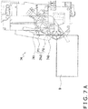
- FIG. 7A to FIG. 7D are views showing operations by which the second major flap Zfa2 is folded by the first face retaining units 741 and the second face retaining units 742. Below, the operations performed by the second major flap folding mechanism 74 will be described with reference to these drawings.
- FIG. 7A is a side view of the second major flap folding mechanism 74 when the first face retaining units 741 and the second face retaining units 742 have sucked hold of the second major flap Zfa2 before folding it.
- the first face retaining units 741 and the second face retaining units 742 are lined up so that the second face retaining units 742 are positioned under the first face retaining units 741, and the suction surfaces of the first suction cups 741a and the second suction cups 742a are positioned in the same vertical plane.
- the relative angle between the first face retaining units 741 and the second face retaining units 742 at this time is 180°.
- the second major flap Zfa2 of the cardboard box B that has reached the front of the first face retaining units 741 and the second face retaining units 742 is pulled close to the first face retaining units 741 and the second face retaining units 742 by another mechanism not shown in the drawings.
- the first suction cups 741a and the second suction cups 742a suck hold of the outer surface of the second major flap Zfa2 that has come in front of them because they are sucking. At this time, the first suction cups 741a suck hold of the first face F1, and the second suction cups 742a suck hold of the second face F2.
- FIG. 7B is a side view of the second major flap folding mechanism 74 when the first face retaining units 741 and the second face retaining units 742 are sucking hold of the second major flap Zfa2 and have started folding it.
- the first face retaining units 741 and the second face retaining units 742 incline in the direction of the inside of the cardboard box B while continuing to suck hold of the outer surface of the second major flap Zfa2.
- the frame 74a that anchors the first face retaining units 741 and the second face retaining units 742 is pivoted a predetermined angle ⁇ a by the drive motor 745, whereby the first face retaining units 741 and the second face retaining units 742 integrally incline the predetermined angle ⁇ a in the direction of the inside of the cardboard box B.
- FIG. 9 is a table showing the relationship between a length A of the first face F1, a length X of the second face F2, and the predetermined angle ⁇ a.
- the illustration above the table shows the side faces of the first face F1 and the second face F2 after the second major flap Zfa2 has been mountain-folded at the bend line BL.
- the predetermined angle ⁇ a also changes in accompaniment therewith.
- a bend angle ⁇ b is calculated from the length A of the first face F1, the length X of the second face F2, the predetermined angle ⁇ a, and the distance D.
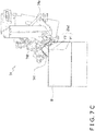
- FIG. 7C is a side view of the second major flap folding mechanism 74 when the first face retaining units 741 and the second face retaining units 742 have bent the second major flap Zfa2 into a mountain shape.
- the first face retaining units 741 pivot so that the relative angle they form with the second face retaining units 742 becomes the calculated bend angle ⁇ b.
- the extension of the pistons 744a of the crank air cylinders 744 turns the parallel cranks 743 coupled to the back sides of the first face retaining units 741, whereby the first face retaining units 741 pivot so that the distal end of the first face F1 lands on, or in front of, the slit portions-of the slit Slt3 in the first minor flap Zfa3 and the slit Slt4 in the second minor flap Zfa4 that were folded before-that are parallel to the distal end of the first face F1.
- the first suction cups 741a continue to suck hold of the first face F1 and the second suction cups 742a continue to suck hold of the second face F2, and the distal end of the first face F1 lands on or in front of the slit portions as a result of the first face retaining units 741 pivoting.
- the mountain-folding operation at the bend angle ⁇ b is performed after the second major flap Zfa2 has been inclined the predetermined angle ⁇ a with respect to the vertical plane
- the mountain-folding operation is not limited to this.
- the mountain-folding operation can also be configured in such a way that the second major flap Zfa2 is first folded until its inner surface touches the outer surfaces of the first minor flap Zfa3 and the second minor flap Zfa4 and thereafter, while pivoting the second major flap Zfa2 in the opposite direction, the first face retaining units 741 are pivoted so that the relative angle between the first face retaining units 741 and the second face retaining units 742 becomes the bend angle ⁇ b.
- the distal end of the first face F1 moves backward, and the distal end of the first face F1 reaches the top of, or the front of, the slit portions.
- FIG. 7D is a perspective view of the second major flap folding mechanism 74 when the first face retaining units 741 and the second face retaining units 742 have extended the second major flap Zfa2.
- the first face retaining units 741 and the second face retaining units 742 extend, into a flat planar shape, the second major flap Zfa2 that had been bent into a mountain shape.
- the first face retaining units 741 pivot so that the relative angle between the first face retaining units 741 and the second face retaining units 742 becomes 180°.
- the first suction cups 741a continue to suck hold of the first face F1 and the second suction cups 742a continue to suck hold of the second face F2, and the first face retaining units 741 pivot so that the relative angle they form with the second face retaining units 742 becomes 180°.
- the first suction cups 741a spread open the first face F1 in a direction away from the second face F2.
- the distal end of the first face F1 goes under the first minor flap Zfa3 and the second minor flap Zfa4 through the slit portions-of the slit Slt3 in the first minor flap Zfa3 and the slit Slt4 in the second minor flap Zfa4-that are parallel to the distal end of the first face F1.
- release operations can be performed at an arbitrary pivot angle of the second major flap Zfa2.
- the second major flap Zfa2 is released in an arbitrary position and enters the slit Slt3 in the first minor flap Zfa3 and the slit Slt4 in the second minor flap Zfa4, the second major flap Zfa2 naturally transitions to a horizontal state.
- the second major flap Zfa2 that has been bent is extended, whereby the distal end of the second major flap Zfa2 enters the slit Slt3 in the first minor flap Zfa3 and the slit Slt4 in the second minor flap Zfa4, so an unnecessary load is not applied to the second major flap Zfa2, there is also no buckling of the second major flap Zfa2, and the distal end thereof becomes easily inserted into the slit Slt3 in the first minor flap Zfa3 and the slit Slt4 in the second minor flap Zfa4.
- the second major flap folding mechanism 74 of the lid forming device 340 bends the second major flap Zfa2 by retaining the second major flap Zfa2 with the first face retaining units 741 and the second face retaining units 742 and individually moving the first face retaining units 741 and the second face retaining units 742 until the relative angle between the first face F1 and the second face F2 of the second major flap Zfa2 decreases to the predetermined angle (90°). Therefore, loads can be applied equally to the first face F1 and the second face F2, and bending defects are reduced.
- the second major flap folding mechanism 74 of the lid forming device 340 places the distal end of the second major flap Zfa2 that has been bent into a mountain shape along the top of, or the upper surface in front of, the slit portions-of the slit Slt3 in the first minor flap Zfa3 and the slit Slt4 in the second minor flap Zfa4-that are parallel to the distal end of the first face F1 and at the same time individually moves the first face retaining units 741 and the second face retaining units 742 in directions in which the relative angle between the first face F1 and the second face F2 of the second major flap Zfa2 increases, and guides the distal end of the second major flap Zfa2 to the slit Slt3 in the first minor flap Zfa3 and the slit Slt4 in the second minor flap Zfa4.
- the first face retaining units 741 have the first suction cups 741a that suck hold of the first face F1
- the second face retaining units 742 have the second suction cups 742a that suck hold of the second face F2, so compared to a case where the second major flap Zfa2 is mechanically caught, concentration of stress in the second major flap Zfa2 is mitigated, and deformation and the like can be inhibited.
- the first face retaining units 741 have the first covers 741b that surround parts of the peripheries of the first suction cups 741a, and the second face retaining units 742 have the second covers 742b that surround parts of the peripheries of the second suction cups 742a.
- the first suction cups 741a simply suck hold of the first face F1 and the second suction cups 742a simply suck hold of the second face F2
- the first covers 741b fulfill the role of transmitting force to the first face F1 during bending
- the second covers 742b fulfill the role of transmitting force to the second face F2 so the first suction cups 741a and the second suction cups 742a are inhibited from sustaining damage due to friction.
- the second major flap Zfa2 is released, the distal end of the first face F1 enters the slit Slt3 in the first minor flap Zfa3 and the slit Slt4 in the second minor flap Zfa4, and the second major flap Zfa2 naturally transitions to a horizontal state. Therefore, the timing when the distal end of the second major flap Zfa2 enters the slit Slt3 in the first minor flap Zfa3 and the slit Slt4 in the second minor flap Zfa4 becomes unstrict.
- the case closing method resulting from the lid forming device pertaining to the above embodiment is usually called a slide lock, and the four top flaps Zfa must be folded inward in a prescribed order.
- a hook-shaped member is rotated by a simple rotating mechanism to catch and outwardly pull up the inwardly collapsed flap, when the length of the box is short, the hook hits the opposing flap and conversely ends up collapsing the flap inward.
- a rotary air cylinder has been attached to the distal end of a linear air cylinder, and the hook-shaped member has been attached to the rotary air cylinder.
- the rotary air cylinder rotates as the linear air cylinder extends from above toward the distal end of the flap, and the linear cylinder retracts after catching the inwardly collapsed flap, whereby the flap is outwardly pulled up and retained.
- a freely rotating pinion gear is attached to the distal end of one linear air cylinder anchored in the horizontal direction.
- the pinion gear meshes with a rack gear anchored in the horizontal direction to form a rack and pinion mechanism.
- FIG. 8 is a perspective view of a hook-shaped member 751 that is operated by a rack and pinion mechanism 753.
- the hook-shaped member 751 is attached to a shaft 751a to which a pinion gear 753a is anchored, and a piston 755a of a hook air cylinder 755 linearly moves, whereby the hook-shaped member 751 pivots while moving in the horizontal direction along a rack 753b.
- the circular path traced by the distal end of the hook-shaped member 751 is defined, and the hook-shaped member 751 moves on a path in which it pulls up the inwardly collapsed flap (the second minor flap Zfa4) without hitting the opposing flap (the first minor flap Zfa3).
- the hook-shaped member 751 is operated by the one hook air cylinder 755, so the air tube is not cumbersome. Furthermore, the circular path traced by the hook-shaped member 751 is always fixed regardless of the operating speed, so the flap (the second minor flap Zfa4) can be stably pulled up regardless of the air flow rate.
- the first suction cups 741a, the second suction cups 742a, the crank air cylinders 744, and the drive motor 745 are combined to perform the operation of folding the second major flap Zfa2.
- crank air cylinders 744 simply have sensors that detect the starting point and the ending point of the operation of the pistons 744a, and cannot measure in real time the operating time of the pistons 744a.
- the controller 40 stores, as the operating time of the pistons 744a, the time interval between the starting point and the ending point of the most recent operation of the pistons 744a and, in accordance with that operating time, changes to an optimal state the operating pattern (speed, acceleration, deceleration) of the drive motor 745 and the cancellation timing of the first suction cups 741a and the second suction cups 742a.
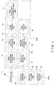
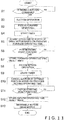
- FIG. 10 is a block diagram showing electrical connections between the controller 40, the first suction cups 741a, the second suction cups 742a, the pistons 744a of the crank air cylinders 744, and the drive motor 745. Furthermore, FIG. 11 is a flowchart of operations of folding the second major flap Zfa2.
- first suction valves 741v connected to the controller 40 are first suction valves 741v, second suction valves 742v, direction switching valves 744v, a first position sensor 744ss, a second position sensor 744sf, and the drive motor 745.
- the first suction valves 741v are valves that cause the first suction cups 741a to suck or cancel the suction.
- the first suction valves 741v When the first suction valves 741v are open, the first suction cups 741a perform the suction operation, and when the first suction valves 741v are closed, the first suction cups 741a cancel the suction.
- the second suction valves 742v are valves that cause the second suction cups 742a to suck or cancel the suction.
- the second suction valves 742v When the second suction valves 742v are open, the second suction cups 742a perform the suction operation, and when the second suction valves 742v are closed, the second suction cups 742a cancel the suction.
- the direction switching valves 744v are valves that cause the pistons 744a of the crank air cylinders 744 to reciprocally operate. When the direction switching valves 744v are in forward mode, the pistons 744a move on a forward path, and when the direction switching valves 744v are in return mode, the pistons 744a move on a return path.
- the first position sensor 744ss is a sensor that detects that the pistons 744a are in a starting point position. Furthermore, the second position sensor 744sf is a sensor that detects that the pistons 744a are positioned in an ending point of the forward path.
- the drive motor 745 is a servo motor. When the drive motor 745 rotates, the frame 74a pivots, so the first face retaining units 741 and the second face retaining units 742 integrally pivot.
- step S1 the controller 40 determines whether or not there is a suction command. When the controller 40 determines that there is a suction command, it proceeds to step S2. When the controller 40 does not determine that there is a suction command, it continues the determination operation.
- step S2 the controller 40 opens the first suction valves 741v and the second suction valves 742v to cause the first suction cups 741a to suck hold of the first face F1 and cause the second suction cups 742a to suck hold of the second face F2.
- step S3 the controller 40 switches the direction switching valves 744v to the forward mode in which the pistons 744a move in the forward direction. Because of this, the pistons 744a operate and the operation of mountain-folding the second major flap Zfa2 is started.
- step S4 the controller 40 starts a timer 405 and counts an amount of elapsed time t since the point in time when it was detected via the first position sensor 744a that the pistons 744a left the starting point position.
- step S5 the controller 40 operates the drive motor 745 to incline the second major flap Zfa2 the angle ⁇ a with respect to the vertical plane.
- the drive motor 745 operates later than the operation of the pistons 744a.
- controller 40 estimates the position of the pistons 744a on the basis of the forward operating time that it stored the previous time and adjusts the acceleration, speed, and deceleration of the drive motor 745 on the basis of the estimated position.
- step S6 the controller 40 determines via the second position sensor 744sf whether or not the pistons 744a have reached the ending point position in the forward direction. When the controller 40 determines that the pistons 744a have reached the ending point position, it proceeds to step S7, and when the controller 40 does not determine that the pistons 744a have reached the ending point position, it continues the determination.
- step S7 the controller 40 stores, in a memory 403 as a forward operating time tA (n) of the pistons 744a, the amount of elapsed time t from the point in time when it was detected that the pistons 744a left the starting point position to the point in time when it was detected that the pistons 744a reached the ending point position and resets the timer 405.
- controller 40 estimates the position of the pistons 744a on the basis of the forward operating time tA (n - 1) that it stored the previous time and adjusts the acceleration, speed, and deceleration of the drive motor 745 on the basis of the estimated position.
- the forward operating time tA (n) that has been stored here is utilized for position estimation in the subsequent (n + 1) forward operation of the pistons 744a.
- step S8 the controller 40 switches the direction switching valves 744v to the return mode in which the pistons 744a move in the return direction.
- step S9 the controller 40 starts the timer 405 and counts the amount of elapsed time t since the point in time when it was detected via the second position sensor 744sf that the pistons 744a left the ending point position.
- step S10 the controller 40 estimates the position of the pistons 744a on the basis of the return operating time that it stored the previous time and, on the basis of the estimated position, cancels the suction of the first face F1 by the first suction cups 741a and the suction of the second face F2 by the second suction cups 742a. Specifically, the controller 40 closes the first suction valves 741v and the second suction valves 742v to thereby cancel the suction of the first face F1 by the first suction cups 741a and the suction of the second face F2 by the second suction cups 742a.
- step S11 the controller 40 determines via the first position sensor 744ss whether or not the pistons 744a have reached the starting point position. When the controller 40 determines that the pistons 744a have reached the starting point position, it proceeds to step S12. When the controller 40 does not determine that the pistons 744a have reached the starting point position, it continues the determination.
- step S12 the controller 40 stores, in the memory 403 as a return operating time tB (n) of the pistons 744a, the amount of elapsed time t from the point in time when it was detected that the pistons 744a left the ending point position to the point in time when it was detected that the pistons 744a reached the starting point position and resets the timer 405.
- the controller 40 estimates the position of the pistons 744a on the basis of the return operating time tB (n - 1) that it stored the previous time and adjusts, on the basis of the estimated position, the timing when it cancels the suction of the first face F1 by the first suction cups 741a and the timing when it cancels the suction of the second face F2 by the second suction cups 742a.
- step S13 the controller 40 reversely rotates the drive motor 745 to thereby cause the first suction cups 741a and the second suction cups 742a to pivot the angle ⁇ a so that they become parallel to the vertical plane.
- the controller 40 adjusts the acceleration, speed, and deceleration of the drive motor 745, the timing when it cancels the suction of the first face F1 by the first suction cups 741a, and the timing when it cancels the suction of the second face F2 by the second suction cups 742a on the basis of the previous forward operating time and return operating time of the pistons 744a.
- the controller 40 adjusts the acceleration, speed, and deceleration of the drive motor 745 on the basis of the previous forward operating time of the pistons 744a, the distal end portion of the first face F1 of the second major flap Zfa2 can reach the intended position of the slit Slt3 and the slit Slt4.
- the controller 40 adjusts the timing when it cancels the suction of the first face F1 by the first suction cups 741a and the suction of the second face F2 by the second suction cups 742a on the basis of the previous return operating time of the pistons 744a, the suction of the first face F1 by the first suction cups 741a and the suction of the second face F2 by the second suction cups 742a is cancelled after the first face retaining units 741 and the second face retaining units 742 finish extending the second major flap Zfa2.
- the structure of a third embodiment is the same as that of the first embodiment and the second embodiment, but the operation of inserting the second major flap Zfa2 into the slit Slt3 and the slit Slt4 differs from that of the first embodiment and the second embodiment.
- FIG. 12A is a schematic view showing a normal operation of inserting the second major flap Zfa2.
- FIG. 12B is a schematic view showing an operation of inserting the second major flap Zfa2 in a case where the fill rate of the bags (products G) in the cardboard box B is high.
- the second major flap folding mechanism 74 inserts the corner of the distal end portion of the first face F1 of the second major flap Zfa2 deep inside through the slit Slt3 and the slit Slt4, thereafter lifts up the second major flap Zfa2 to an extent that the corner of the distal end portion of the first face F1 does not come out of the slit Slt3 and the slit Slt4, and then reinserts the distal end portion of the first face F1.
- FIG. 12C is a schematic view showing an operation of inserting the second major flap Zfa2 in the third embodiment.
- the second major flap folding mechanism 74 inserts the corner of the distal end portion of the first face F1 of the second major flap Zfa2 that has been bent into a mountain shape into the slit Slt3 and the slit Slt4.
- a first range of the corner of the distal end portion that is a first dimension L1 from the free end of the first face F1 is inserted into the slit Slt3 and the slit Slt4. This state will be called a first insertion state.
- a second range of the corner of the distal end portion that is a second dimension L2 smaller than the first dimension L1 from the free end of the first face F1 is inserted into the slit Slt3 and the slit Slt4. This state will be called a second insertion state.
- the second major flap folding mechanism 74 extends the second major flap Zfa2 and inserts the corner of the distal end portion that has been inserted into the slit Slt3 and the slit Slt4 further toward the far sides of the slit Slt3 and the slit Slt4 as a second operation.
- the covers can be opened by the first insertion state, so failure to insert the second major flap Zfa2 due to the presence of covers is avoided.
- a sensor can also be used to determine whether or not the insertion operation has been completed normally.
- FIG. 13 is a schematic view showing a series of operations performed by the second major flap folding mechanism 74 when the operation of inserting the second major flap Zfa3 has not been completed normally.
- a sensor 746 is a photoelectric sensor.
- the sensor 746 has a light transmitter 746a and a light receiver 746b.
- the light transmitter 746a and the light receiver 746b are disposed a predetermined interval apart from each other at a predetermined height position, and light (e.g., infrared) is projected from the light transmitter 746a.
- the controller 40 judges that there is no object detected between the light transmitter 746a and the light receiver 746b if the light is not blocked and is detected by the light receiver 746b.
- the predetermined height position is set to a position a predetermined distance higher than the upper end of the cardboard box B.
- the controller 40 judges that the operation of inserting the second major flap Zfa2 was not completed normally. Then, as shown in FIG. 13 , the controller 40 tilts the first face retaining units 741 and the second face retaining units 742 in the direction of the cardboard box B to thereby push in the second major flap Za2.
- the controller 40 can also suck hold of the second major flap Zfa2 via the first face retaining units 741 and the second face retaining units 742 and perform the folding operation again.
- the structure of a fourth embodiment differs from that of the first embodiment in that the mountain-folding operation of bending the second major flap Zfa2 along the bend line BL is performed by servo motors 747 instead of the crank air cylinders 744.
- the second major flap Zfa2 is bent along the bend line BL by the mountain-folding operation, so if the position of the bend line BL changes, the combination of the length A of the first face F1 and the length X of the second face F2 becomes different, and the predetermined angle ⁇ a is also changed to make an adjustment so that the distal end of the first face F1 after being bent reaches an appropriate landing point.
- the bend angle ⁇ b is calculated from the length A of the first face F1, the length X of the second face F2, the predetermined angle ⁇ a, and the distance D, and in the first embodiment the bend angle ⁇ b is fixed at 90°.
- the first face retaining units 741 are pivoted by the servo motors 747 in order to make it easier to set the relative angle between the first face retaining units 741 and the second face retaining units 742 to the desired bend angle ⁇ b.
- the bend angle ⁇ b is set in the range of 90 to 120 degrees.
Landscapes
- Engineering & Computer Science (AREA)
- Mechanical Engineering (AREA)
- Closing Of Containers (AREA)
Abstract
Description
- This application claims priority to Japanese Applications No.
2019-023644, filed on February 13, 2019 2019-200477, filed on November 5, 2019 - The present invention relates to a lid forming device, and particularly relates to a device that forms lids of cardboard boxes.
- Conventionally, as devices that form lids of cardboard boxes, devices that form slits or the like beforehand in flaps folded first out of a group of flaps provided on edges of an opening of cardboard and thereafter insert into those slits a distal end of a flap folded last are known. For example, Japanese Examined Patent Publication No.
S58-3881 - However, among cardboard boxes, there are also cardboard boxes that are reutilized, and there are cases where the flaps themselves do not retain their initial hardness and strength. When the second flaps in this state are bent and the bent portions are pushed in, there is the concern that the second flaps will buckle at their distal ends, whose strength is weak, and that the distal ends of the second flaps will not be inserted into the long holes in the first flaps.
- It is a problem of the present invention to provide a lid forming device having a configuration with which part of a flap is easily inserted into slits in other flaps of a cardboard box.
- A lid forming device pertaining to a first aspect of the invention forms a lid of a cardboard box using, out of a group of flaps provided like cantilevers on edges of an opening of the cardboard box, a first flap in which slit is formed and a second flap that becomes extended after being bent into a mountain shape. The lid forming device has a first folding mechanism and a second folding mechanism. The first folding mechanism folds the first flap in directions in which the first flap closes the opening. The second folding mechanism bends into a mountain shape and then extends the second flap and, in the process of extending the second flap, inserts part of the second flap into the slit in the first flap. The second folding mechanism includes first retaining unit and second retaining unit. The first retaining unit retains a first face between a free end of the second flap and a bend line set beforehand in the second flap. The second retaining unit retains a second face between an anchored end of the second flap and the bend line.
- In this lid forming device, the bent portion of the second flap is extended, whereby the distal end of the second flap enters the slit in the first flap, so an unnecessary load is not applied to the second flap, there is also no buckling of the second flap, and the distal end thereof becomes easily inserted into the slit.
- A lid forming device pertaining to a second aspect of the invention is the lid forming device pertaining to the first aspect, wherein the second folding mechanism retains the second flap by using the first retaining unit and the second retaining unit to bend the second flap and individually moving the first retaining unit and the second retaining unit until the relative angle between the first face and the second face of the second flap decreases to a predetermined angle.
- In this lid forming device, the first face and the second face of the second flap are individually moved, so loads can be applied equally to both faces, and bending defects are reduced.
- A lid forming device pertaining to a third aspect of the invention is the lid forming device pertaining to the first aspect or the second aspect, wherein the second folding mechanism places, along upper surfaces of the first flap, a distal end of the second flap that has been bent, at the same time individually moves the first retaining unit and the second retaining unit in directions in which the relative angle between the first face and the second face of the second flap increases, and guides the free end of the second flap to the slit in the first flap.
- In this lid forming device, the second folding mechanism places the distal end of the second flap along the upper surfaces of the first flap and at the same time extends the second flap in directions in which the relative angle between the first face and the second face of the second flap increases, so an unnecessary load is not applied to the second flap, and the distal end of the second flap is smoothly inserted into the slit in the first flap without becoming deformed.
- A lid forming device pertaining to a fourth aspect of the invention is the lid forming device pertaining to any one of the first aspect to the third aspect, wherein the first retaining unit has a first suction device that sucks hold of the first face. Furthermore, the second retaining unit has a second suction device that sucks hold of the second face.
- In this lid forming device, the first retaining unit and the second retaining unit are a suction type, so compared to a case where the second major flap is mechanically caught, concentration of stress in the flap is mitigated, and deformation and the like can be inhibited.
- A lid forming device pertaining to a fifth aspect of the invention is the lid forming device pertaining to the fourth aspect, wherein the first retaining unit further has a first cover that surrounds a part of the peripheries of the first suction device. Furthermore, the second retaining unit further has a second cover that surrounds a part of the peripheries of the second suction device.
- In this lid forming device, when bending the second flap, the first suction device simply sucks hold of the first face and the second suction device simply sucks hold of the second face, and the first cover fulfills the role of transmitting force to the first face during the bending and the second cover fulfills the role of transmitting force to the second face, so the first suction device and the second suction device are inhibited from sustaining damage due to friction.
- A lid forming device pertaining to a sixth aspect of the invention is the lid forming device pertaining to the fourth aspect, wherein the first suction device selectively switches the timing when it releases the first face after it has sucked hold of the first face. Furthermore, the second suction device selectively switches the timing when it releases the second face after it has sucked hold of the second face.
- A lid forming device pertaining to a seventh aspect of the invention is the lid forming device pertaining to the first aspect, wherein the second folding mechanism performs a first operation and a second operation. The first operation is an operation in which it inserts into the slit a predetermined portion of the first face of the second flap that has been bent into a mountain shape. The second operation is an operation in which it extends the second flap after the first operation and further inserts toward far sides of the slits the predetermined portion that has been inserted into the slit.
- In this lid forming device, even if strain arises in the slit in the first flap due, for example, to reutilization of the cardboard box, the predetermined portion of the first face is reliably inserted further toward the deep sides of the slit as a result of the second flap extending from a state in which the predetermined portion of the first face of the second flap is inserted into the slit.
- A lid forming device pertaining to an eighth aspect of the invention is the lid forming device pertaining to the seventh aspect, wherein in the first operation the second folding mechanism forms a first insertion state and thereafter forms a second insertion state. The first insertion state is a state in which a first range of the predetermined portion that is a first dimension away from the free end of the first face is inserted into the slit. The second insertion state is a state in which a second range of the predetermined portion that is a second dimension smaller than the first dimension away from the free end of the first face is inserted into the slit.
- In this lid forming device, even in a case where the fill rate of the bags in the cardboard box is high, a space for the second flap to slide into can be ensured by forming the first insertion state in which the second flap is inserted deep into the slit.
- A lid forming device pertaining to a ninth aspect of the invention is the lid forming device pertaining to the first aspect, wherein the second folding mechanism further has a drive unit. The drive unit drive the first retaining unit and the second retaining unit until the relative angle between the first face and the second face of the second flap becomes a predetermined angle.
- In this lid forming device, when bending the second flap into a mountain shape, the second flap can be bent to an angle suited for inserting the second flap into the slit.
- A lid forming device pertaining to a tenth aspect of the invention is the lid forming device pertaining to the ninth aspect, wherein the predetermined angle is set in the range of 90 to 120 degrees.
- A lid forming device pertaining to an eleventh aspect of the invention is the lid forming device pertaining to the first aspect, and further has a control unit that controls the second folding mechanism. The second folding mechanism further includes a first drive unit, a second drive unit, a third drive unit, and a measuring unit. The first drive unit causes the second flap to pivot about the anchored end of the second face. The second drive unit performs retention and releases of the first face and the second face of the second flap by means of the first retaining unit and the second retaining unit. The third drive unit drives the first retaining unit and the second retaining unit until the relative angle between the first face and the second face of the second flap becomes a predetermined angle. The measuring unit measures, and outputs to the control unit, at least the operating time of the third drive unit. The control unit adjusts the operation of the first drive unit and/or the operation of the second drive unit on the basis of the operating time of the third drive unit.
- In this lid forming device, even when the operation of the third drive unit is unstable and the time until the relative angle between the first face and the second face of the second flap becomes the predetermined angle is not stable, the series of operations of the second folding mechanism becomes stable as a result of the first drive unit and the second drive unit performing operations suited to the operating time of the third drive unit.
- A lid forming device pertaining to a twelfth aspect of the invention is the lid forming device pertaining to the eleventh aspect, wherein the first drive unit is a servo motor and the third drive unit is an air cylinders.
- A lid forming device pertaining to a thirteenth aspect of the invention is the lid forming device pertaining to the first aspect, and further has a control unit and a detection unit. The control unit controls the second folding mechanism. The detection unit detects, and outputs to the control unit, the height position, from a predetermined reference surface, of the second flap that has been folded by the second folding mechanism. The control unit causes the second folding mechanism to refold the second flap when it has judged that the height position is not in a predetermined range.
- In this lid forming device, even if a folding defect occurs, the second folding mechanism automatically retries folding the second flap, so it is not necessary for the operator to stop the device, and a reduction in the operating rate of the device can be inhibited.
- In the lid forming device pertaining to the invention, the bent portion of the second flap is extended, whereby the distal end of the second flap enters the slit in the first flap, so an unnecessary load is not applied to the second flap, there is also no buckling of the second flap, and the distal end thereof becomes easily inserted into the slit.
-
-
FIG. 1 is a block diagram of a box packing system equipped with a lid forming device pertaining to a first embodiment of the invention. -
FIG. 2A is a perspective view showing the configuration of the box packing system. -
FIG. 2B is a perspective view showing a flow of cardboard boxes and products in the box packing system. -
FIG. 3A is perspective view of a cardboard box before top flaps are folded. -
FIG. 3B is a perspective view showing, in three stages, a process of folding the top flaps inFIG. 3A . -
FIG. 4 is a perspective view of main portions of the lid forming device. -
FIG. 5 is a perspective view of a second major flap folding mechanism. -
FIG. 6 is a perspective view of first face retaining units and second face retaining units when they are seen from their back sides. -
FIG. 7A is a side view of the second major flap folding mechanism when the first face retaining units and the second face retaining units have sucked hold of a second major flap before folding it. -
FIG. 7B is a side view of the second major flap folding mechanism when the first face retaining units and the second face retaining units are sucking hold of the second major flap and have started folding it. -
FIG. 7C is a side view of the second major flap folding mechanism when the first face retaining units and the second face retentions unit have bent the second major flap into a mountain shape. -
FIG. 7D is a perspective view of the second major flap folding mechanism when the first face retaining units and the second face retaining units have extended the second major flap. -
FIG. 8 is a perspective view of a hook-shaped member that is operated by a rack and pinion mechanism. -
FIG. 9 is a table showing the relationship between the length of a first face, the length of a second face, and a predetermined angle. -
FIG. 10 is a block diagram showing electrical connections between a controller, first suction cups, second suction cups, pistons of crank air cylinders, and a drive motor. -
FIG. 11 is a flowchart of operations of folding the second major flap. -
FIG. 12A is a schematic view showing a normal operation of inserting the second major flap. -
FIG. 12B is a schematic view showing an operation of inserting the second major flap in a case where the fill rate of bags (products) in a cardboard box is high. -
FIG. 12C is a schematic view showing an operation of inserting the second major flap in a third embodiment. -
FIG. 13 is a schematic view showing a series of operations performed by the second flap folding mechanism when the operation of inserting the second major flap has not been completed normally. -
FIG. 14 is a schematic side view of the second major flap folding mechanism in a fourth embodiment. - Embodiments of the invention will be described below with reference to the drawings. It will be noted that the following embodiments are specific examples of the invention and are not intended to limit the technical scope of the invention.
-
FIG. 1 is a block diagram of abox packing system 1 equipped with a cardboard box erector pertaining to a first embodiment of the invention. Furthermore,FIG. 2A is a perspective view showing the configuration of thebox packing system 1, andFIG. 2B is a perspective view showing a flow of cardboard boxes B and products G in thebox packing system 1. - In
FIG. 1 andFIG. 2A , thebox packing system 1 packs a fixed number of bagged products (products G), such as snack foods for example, in an aligned state and in multiple layers into cardboard boxes B. - As shown in
FIG. 1 andFIG. 2A , thebox packing system 1 comprises a cardboard box handling area DHA and a product handling area GHA that are interconnected in a state in which they are mutually independently separable. The cardboard box handling area DHA includes two processes, a case forming process P1 and a box packing process P3. The product handling area GHA includes a product aligning process P2. - That is, in the
box packing system 1, the three processes of the case forming process P1, the product aligning process P2, and the box packing process P3 work together as a result of the cardboard box handling area DHA and the product handling area GHA being interconnected. - The case forming process P1 is a process of erecting sheet-like cardboard box precursors Z into cardboard boxes B and conveying the cardboard boxes B to a box packing position. The case forming process P1 is configured by a box
precursor accommodating unit 11, acase forming unit 12, a firstposture converting unit 13, and a box downward conveyingunit 14. - The product aligning process P2 is a process of feeding to a predetermined position the products G that are supplied from an upstream process, aligning a fixed number of the products G so that adjacent products partially lie on top of each other, and conveying the fixed number of products G to the box packing position. The product aligning process P2 is configured by a
product feeding unit 21, aproduct aligning unit 22, and aproduct inserting unit 23. - The box packing process P3 is a process of packing, into the cardboard boxes B that have been conveyed thereto from the case forming process P1, the fixed quantity of the products G that have finished being aligned in the product aligning process P2, closing the boxes, and conveying the boxes to a box discharge position. The box packing process P3 is configured by a
product receiving unit 31, a secondposture converting unit 32, and acase closing unit 33. - The
box packing system 1 performs multilayer packing of the products G into the cardboard boxes B, and the posture of the products G inside the cardboard boxes B is a "standing posture." That is, the standing posture is a posture where, when the openings of the cardboard boxes B face up, the front sides and the back sides of the products G face sideways, the upper and lower end portions of the products G face up and down, and the left and right side portions of the products G face sideways. - Furthermore, as shown in
FIG. 2A andFIG. 2B , the cardboard box handling area DHA has a two-level structure, and the case forming process P1 and the box packing process P3 are supported by acommon frame 10. The case forming process P1 occupies the second-level portion, and the box packing process P3 occupies the first-level portion. - In order to realize this two-level structure, the conveyance direction of the cardboard boxes B from the erection of the cardboard boxes B by the
case forming unit 12 to the box downward conveyingunit 14 and the conveyance direction of the cardboard boxes B up to when the openings of the cardboard boxes B that have been packed with the products G are closed by thecase closing unit 33 are mutually opposite directions. - As shown in
FIG. 2B , the case forming process P1 is configured by the boxprecursor accommodating unit 11 that introduces the cardboard box precursors Z to thebox packing system 1, thecase forming unit 12 that erects the cardboard boxes B, the firstposture converting unit 13 that rotates thecardboard boxes B 90° about a horizontal axis orthogonal to the conveyance direction, and the box downward conveyingunit 14 that conveys downward the cardboard boxes B that have been converted to a first posture. - As shown in
FIG. 2B , the boxprecursor accommodating unit 11 takes hold of one at a time and transports upward the cardboard box precursor Z at the very front of the cardboard box precursors Z stacked in a supply position and rotates the transported cardboardbox precursor Z 90° about a vertical axis to thereby open it into a tubular shape. - The cardboard box precursors Z are placed in the supply position by a worker. The cardboard box precursors Z are collapsed with their flaps Zf open and are stacked in a horizontal direction in a posture in which the flaps Zf are positioned in the vertical direction. It will be noted that for convenience of description the flaps Zf on the top surface side will be called top flaps Zfa and the flaps Zf on the bottom surface side will be called bottom flaps Zfb.
- The upward transport of the cardboard box precursors Z is performed by a
lift mechanism 111. When all the cardboard box precursors Z in the supply position run out, a detection sensor (not shown in the drawings) sends a detection signal to a controller 40 (seeFIG. 1 ). - Furthermore, the rotation of the cardboard box precursors Z about the vertical axis is realized by sucking and holding, with suction cups, the side surfaces of the cardboard box precursors Z with a sucking and
rotating mechanism 112 and rotating the sucking androtating mechanism 112 90° about the vertical axis. - The
case forming unit 12 conveys in a horizontal direction the cardboard box precursors Z that have been opened into a tubular shape and at the same time folds the bottom flaps Zfb of the cardboard box precursors Z to form bottoms, thereby erecting the cardboard boxes B which are in a state in which their top flaps Zfa are open. - The first
posture converting unit 13 rotates thecardboard boxes B 90° in the conveyance direction. More specifically, the firstposture converting unit 13 rotates thecardboard boxes B 90° about a horizontal axis orthogonal to the conveyance direction to thereby convert the posture of the cardboard boxes B to a posture (hereinafter called a first posture) in which the openings and the top flaps Zfa of the cardboard boxes B lie in the same vertical plane. When the cardboard boxes B are in the first posture, their openings face the product handling area GHA. - The box downward conveying
unit 14 conveys downward the cardboard boxes B that have been converted to the first posture. That is, the box downward conveyingunit 14 moves the cardboard boxes B downward while keeping the openings of the cardboard boxes B facing the product handling area GHA. - Disposed upstream of the product aligning process P2 in the flow of the products G in the
box packing system 1 are a weigher and a bag-making and packaging machine not shown in the drawings. Only products G that have passed weight, seal, and contamination inspections in the upstream process are supplied to the product aligning process P2 in thebox packing system 1. - The product aligning process P2 is configured by the
product feeding unit 21 that accepts the products G and conveys them to a predetermined position, theproduct aligning unit 22 that aligns the products G that are supplied from theproduct feeding unit 21, and theproduct inserting unit 23 that accumulates and pushes the aligned products G. - The
product feeding unit 21 has aproduct introducing conveyor 211 and afeeding conveyor 212. Theproduct introducing conveyor 211 receives, downstream of the process that performs the weight, seal, and contamination inspections, the supply of the products G that have passed the inspections and leads those products G to thefeeding conveyor 212. - The feeding
conveyor 212 conveys to theproduct aligning unit 22 the products G conveyed thereto from theproduct introducing conveyor 211. - The
product aligning unit 22 has a first aligningconveyor 221, a second aligningconveyor 222, and a third aligningconveyor 223. Theproduct aligning unit 22 conveys the products G to a predetermined position while performing an accumulating operation with respect to the products G. Theproduct aligning unit 22 is particularly suited for accumulating bag-like packages, so it can also be used independently as a package accumulating device. - The
product inserting unit 23 sandwiches the front and rear of the group of products G that have been aligned in a line by the third aligningconveyor 223 and inserts the whole group of products G into the cardboard boxes B. As shown inFIG. 2B , theproduct inserting unit 23 has a stand-upconveyor 231, apush plate 233, and aninsertion plate 235 in order to sandwich the aligned group of products G. - The box packing process P3 has the
product receiving unit 31 that receives the products G into the cardboard boxes B, the secondposture converting unit 32 that converts the posture of the cardboard boxes B so that the openings of the cardboard boxes B face up, and thecase closing unit 33 that conveys the cardboard boxes B that have finished being packed with the products G and at the same time closes the openings of the cardboard boxes B. - The
product receiving unit 31 maintains the cardboard boxes B in the first posture and has the cardboard boxes B stand by with their openings opposing theinsertion plate 235 of theproduct inserting unit 23. An N-number of the products G that have been converted to the standing state in theproduct inserting unit 23 are pushed by theinsertion plate 235 toward the open surfaces of the cardboard boxes B, so theproduct receiving unit 31 stands by in that position until the N-number of the products G are completely inserted through the openings to the bottoms of the cardboard boxes B. - When a first layer of the N-number of the products G is inserted into a cardboard box B, the
product receiving unit 31 descends a predetermined distance. Then, in order to receive a second layer of the N-number of the products G, theproduct receiving unit 31 has the cardboard box B stand by in such a way that the portion of the opening of the cardboard box B that leads to the space above the first layer opposes theinsertion plate 235. - The
product receiving unit 31 repeats the above operations so that an i-th layer of the N-number of the products G is inserted into the cardboard box B, and then the receiving of the products G into the cardboard box B is finished. - As shown in
FIG. 2B , the secondposture converting unit 32 has aposture converting mechanism 321 that converts the posture of the cardboard boxes B packed with the products G to a posture in which the openings face up. - The
posture converting mechanism 321 rotates the cardboard boxes B so that the open surfaces that had been vertical until then become horizontal, namely, so that the open surfaces face up. Theposture converting mechanism 321 retains the cardboard boxes B with an L-shaped member having suction cups that simultaneously suck hold of the side surfaces and the bottom surfaces of the cardboard boxes B, and when the L-shaped member rotates 90°, the cardboard boxes B rotate. - As shown in
FIG. 2B , thecase closing unit 33 has adischarge conveyor 330 that conveys the cardboard boxes B and alid forming device 340 that closes the flaps surrounding the openings of the cardboard boxes B to thereby form lids. - Below, details regarding the
lid forming device 340 will be described. - Here, the operation of folding the top flaps Zfa of the cardboard box B will be mainly described.
- First, before the operation is described, the cardboard box B handled by the
box packing system 1 will be described.FIG. 3A is a perspective view of the cardboard box B before the top flaps Zfa are folded. Furthermore,FIG. 3B is a perspective view showing, in three stages, a process of folding the top flaps Zfa inFIG. 3A . - In
FIG. 3A and FIG. 3B , the top flaps Zfa include a first major flap Zfa1 and a second major flap Zfa2, which are a pair of major flaps that are opposite each other, and a first minor flap Zfa3 and a second minor flap Zfa4, which are a pair of minor flaps that are opposite each other. - The second major flap Zfa2 is provided beforehand with a bend line BL in a portion which, when the second major flap Zfa2 has been folded into a mountain shape, becomes the top of the mountain. The face of the second major flap Zfa2 on the free end side of the bend line BL will be called a first face F1, and the face on the anchored end side of the bend line BL will be called a second face F2.
- In the first minor flap Zfa3 and the second minor flap Zfa4 are formed slits into which the second major flap Zfa2 is inserted. The slit in the first minor flap Zfa3 is a slit Slt3, and the slit in the second minor flap Zfa4 is a slit Zlt4.
- The slits Slt3 and Slt4 are L-shaped and each have first slit portions, which face free end sides of the flaps and are parallel to those free ends, and second slit portions, which face the side ends of the flaps on the second major flap Zfa2 side and are parallel to those side ends.
-
FIG. 3B shows the folding order of the top flaps Zfa. First, the first major flap Zfa1 is folded, then the first minor flap Zfa3 and the second minor flap Zfa4 are folded, and lastly the second major flap Zfb2 is folded. - When folding the second major flap Zfa2, the second major flap Zfa2 is bent into a mountain shape so that the bend line BL forms the top, the distal end of the second major flap Zfa2 is inserted into the second slit portions of the slits Slt3 and Slt4, and then the second major flap Zfa2 is extended, whereby the second major flap Zfa2 slides through the slits Slt3 and Slt4 and under the first major flap Zfa1, and the lid is finished. Because of this, the four top flaps Zfa interfere with each other and become locked.
- The
lid forming device 340 performs the folding of the top flaps Zfa automatically. Below, the operation of folding the top flaps Zfa will be described. -
FIG. 4 is a perspective view of main portions of thelid forming device 340. InFIG. 4 , thelid forming device 340 includes a first major flap folding mechanism 71, a first minorflap folding mechanism 72, a second minorflap folding mechanism 73, and a second majorflap folding mechanism 74. - The mechanisms are arranged in such a way that, heading in the conveyance direction of the cardboard boxes B, the first major flap folding mechanism 71 is disposed on the left side of the
discharge conveyor 330 and the second majorflap folding mechanism 74 is disposed on the right side of thedischarge conveyor 330. Furthermore, the first minorflap folding mechanism 72 is disposed upstream in the conveyance direction of the cardboard boxes B, and the second minorflap folding mechanism 73 is disposed downstream in the conveyance direction of the cardboard boxes B. - Below, these mechanisms will be described in the order in which they operate.
- The first major flap folding mechanism 71 is a mechanism that folds the first major flap Zfa1 and includes a
first folding plate 711, afirst coupling member 713, and afirst air cylinder 715. - The
first folding plate 711 is a plate metal member that has a restraining surface 711a that is a flat rectangular surface. Thefirst folding plate 711 is a plate for folding the first major flap Zfa1. - The
first coupling member 713 is a member that transmits displacement of a piston of thefirst air cylinder 715 to thefirst folding plate 711. - One end of the
first coupling member 713 is coupled to one end of thefirst folding plate 711. Thefirst coupling member 713 has arotational shaft 713a. Therotational shaft 713a is provided in the neighborhood of the portion coupled to thefirst folding plate 711. - The other end of the
first coupling member 713 is connected to a distal end of apiston 715a of thefirst air cylinder 715. When thepiston 715a reciprocates, thefirst coupling member 713 pivots about therotational shaft 713a, so thefirst folding plate 711 swings in accompaniment therewith. - The
first folding plate 711 shown inFIG. 4 is in a standby state before it folds the first major flap Zfa1. When thefirst air cylinder 715 retracts thepiston 715a, thefirst coupling member 713 pivots in the direction of arrow D1 together with thefirst folding plate 711, and thefirst folding plate 711 folds the first major flap Zfa1. - The first minor
flap folding mechanism 72 includes asecond folding plate 721, asecond coupling member 723, and asecond air cylinder 725. - The
second folding plate 721 is a plate metal member that has aquarter arc 721a. The portion of thesecond folding plate 721 connected to thesecond coupling member 723 is provided in a position a predetermined distance away from thequarter arc 721a. Thesecond folding plate 721 is a plate for folding the first minor flap Zfa3. - The
second coupling member 723 is a member that transmits displacement of a piston of thesecond air cylinder 725 to thesecond folding plate 721. - One end of the
second coupling member 723 is coupled to a connecting portion provided on one end side of thesecond folding plate 721. Thesecond coupling member 723 has arotational shaft 723a. Therotational shaft 723a is provided in the neighborhood of the middle portion of thesecond coupling member 723. - The other end of the
second coupling member 723 is connected to a distal end of apiston 725a of thesecond air cylinder 725. When thepiston 725a reciprocates, thesecond coupling member 723 pivots about therotational shaft 723a, so thesecond folding plate 721 swings in accompaniment therewith. - Before the folding operation, the
second folding plate 721 stands by in a position in which its distal end faces the horizontal direction. Thesecond folding plate 721 shown inFIG. 4 is depicted in a position to which it has pivoted in the direction of arrow D2 so that thequarter arc 721a has folded the first minor flap Zfa3. - The second minor
flap folding mechanism 73 includes athird folding plate 731, athird coupling member 733, and athird air cylinder 735. - The
third folding plate 731 is a strip-like plate metal member. Thethird folding plate 731 is a plate for folding the second minor flap Zfa4. - The
third coupling member 733 is a member that transmits displacement of a piston of thethird air cylinder 735. Thethird coupling member 733 is a plate-shaped plate metal member, and one end face thereof is welded to the back face of thethird folding plate 731. Therefore, the principal plane of thethird coupling member 733 and the principal plane of thethird folding plate 731 are perpendicular to each other. It will be noted that what is meant by "the back face of thethird folding plate 731" is the face on the opposite side when the face that comes into contact with the second minor flap Zfa4 is taken to be the outer surface. - The
third coupling member 733 has arotational shaft 733a. Therotational shaft 733a is provided in the end portion of thethird coupling member 733. A connectingmember 733b for connecting apiston 735a of thethird air cylinder 735 is coupled to thethird coupling member 733 in the neighborhood of therotational shaft 733a. - When the
piston 735a reciprocates, thethird coupling member 733 pivots about therotational shaft 733a, so thethird folding plate 731 swings in accompaniment therewith. - The
third folding plate 731 shown inFIG. 4 is in a standby state before it folds the second minor flap Zfa4. When thethird air cylinder 735 extends thepiston 735a, thethird coupling member 733 pivots in the direction of arrow D3 together with thethird folding plate 731, and thethird folding plate 731 folds the second minor flap Zfa4. -
FIG. 5 is a perspective view of the second majorflap folding mechanism 74. InFIG. 5 , the second majorflap folding mechanism 74 is a mechanism that folds the second major flap Zfa2 and includes firstface retaining units 741, secondface retaining units 742,parallel cranks 743, crank air cylinders 744 (seeFIG. 6 ), and adrive motor 745. - The first
face retaining units 741 retain the first face F1 of the second major flap Zfa2 (seeFIG. 3A ). As shown inFIG. 3A , the first face F1 is the face of the second major flap Zfa2 on the free end side of the bend line BL. - The first
face retaining units 741 each include afirst suction cup 741a and afirst cover 741b. Thefirst suction cup 741a has a circular suction surface in the middle of which is formed ahole 741c for suction. Thehole 741c is connected to a suction tube (not shown in the drawings). Thefirst cover 741b is a member that surrounds the periphery of thefirst suction cup 741a. - The second
face retaining units 742 retain the second face F2 of the second major flap Zfa2 (seeFIG. 3 ). As shown inFIG. 3A , the second face F2 is the face of the second major flap Zfa2 on the anchored end side of the bend line BL. - The second
face retaining units 742 each include asecond suction cup 742a and asecond cover 742b. Thesecond suction cup 742a has a circular suction surface in the middle of which is formed ahole 742c for suction. Thehole 742c is connected to a suction tube (not shown in the drawings). Thesecond cover 742b is a member that surrounds the periphery of thesecond suction cup 742a. - It will be noted that, as shown in
FIG. 4 andFIG. 5 , one set each of the firstface retaining unit 741 and the secondface retaining unit 742 is disposed upstream and downstream along the conveyance direction. The firstface retaining units 741 and the secondface retaining units 742 in a standby state are lined up so that the secondface retaining units 742 are positioned under the firstface retaining units 741, and the suction surfaces of thefirst suction cups 741a and thesecond suction cups 742a are positioned in the same vertical plane. - It will be noted that when bending the second major flap Zfa2, the
first suction cups 741a simply suck the first face F1 and thesecond suction cups 742a simply suck the second face F2, whereby thefirst covers 741b fulfill the role of transmitting force to the first face F1 during bending and thesecond covers 742b fulfill the role of transmitting force to the second face F2. -
FIG. 6 is a perspective view of the firstface retaining units 741 and the secondface retaining units 742 when they are seen from their back sides. InFIG. 6 , theparallel cranks 743 are disposed on the back sides of the firstface retaining units 741. The parallel cranks 743 cause, by means of the reciprocating operation ofpistons 744a of thecrank air cylinders 744, the firstface retaining units 741 to pivot so that the firstface retaining units 741 incline a predetermined angle with respect to the secondface retaining units 742. - In the present embodiment, by extending the
pistons 744a, theparallel cranks 743 cause the firstface retaining units 741 to pivot so that the firstface retaining units 741 form a 90° angle with respect to the secondface retaining units 742. - It will be noted that during actual operation the first
face retaining units 741 located upstream and downstream in the conveyance direction pivot synchronously, but inFIG. 5 andFIG. 6 the firstface retaining unit 741 located downstream is depicted in a posture before pivoting and the firstface retaining unit 741 located upstream is depicted in a posture after pivoting in order to express the difference in posture before and after pivoting. - As shown in
FIG. 5 , thedrive motor 745 is disposed on the downstream upper side of thelid forming device 340. Thedrive motor 745 is connected by alink mechanism 74b (seeFIG. 7D ) to aframe 74a that supports the firstface retaining units 741 and the secondface retaining units 742, and when thedrive motor 745 rotates, theframe 74a pivots, so the firstface retaining units 741 and the secondface retaining units 742 integrally pivot. - The second major
flap folding mechanism 74 folds the second major flap Zfa2 after the first major flap Zfa1 has been folded by the first major flap folding mechanism 71, the first minor flap Zfa3 has been folded by the first minorflap folding mechanism 72, and the second minor flap Zfa4 has been folded by the second minorflap folding mechanism 73. -
FIG. 7A to FIG. 7D are views showing operations by which the second major flap Zfa2 is folded by the firstface retaining units 741 and the secondface retaining units 742. Below, the operations performed by the second majorflap folding mechanism 74 will be described with reference to these drawings. - First,
FIG. 7A is a side view of the second majorflap folding mechanism 74 when the firstface retaining units 741 and the secondface retaining units 742 have sucked hold of the second major flap Zfa2 before folding it. InFIG. 7A , the firstface retaining units 741 and the secondface retaining units 742 are lined up so that the secondface retaining units 742 are positioned under the firstface retaining units 741, and the suction surfaces of thefirst suction cups 741a and thesecond suction cups 742a are positioned in the same vertical plane. The relative angle between the firstface retaining units 741 and the secondface retaining units 742 at this time is 180°. - The second major flap Zfa2 of the cardboard box B that has reached the front of the first
face retaining units 741 and the secondface retaining units 742 is pulled close to the firstface retaining units 741 and the secondface retaining units 742 by another mechanism not shown in the drawings. - The
first suction cups 741a and thesecond suction cups 742a suck hold of the outer surface of the second major flap Zfa2 that has come in front of them because they are sucking. At this time, thefirst suction cups 741a suck hold of the first face F1, and thesecond suction cups 742a suck hold of the second face F2. - Next,
FIG. 7B is a side view of the second majorflap folding mechanism 74 when the firstface retaining units 741 and the secondface retaining units 742 are sucking hold of the second major flap Zfa2 and have started folding it. - In
FIG. 7B , the firstface retaining units 741 and the secondface retaining units 742 incline in the direction of the inside of the cardboard box B while continuing to suck hold of the outer surface of the second major flap Zfa2. Specifically, theframe 74a that anchors the firstface retaining units 741 and the secondface retaining units 742 is pivoted a predetermined angle θa by thedrive motor 745, whereby the firstface retaining units 741 and the secondface retaining units 742 integrally incline the predetermined angle θa in the direction of the inside of the cardboard box B. - It will be noted that the predetermined angle θa differs depending on the box specifications of the cardboard box B. For example,
FIG. 9 is a table showing the relationship between a length A of the first face F1, a length X of the second face F2, and the predetermined angle θa. InFIG. 9 , the illustration above the table shows the side faces of the first face F1 and the second face F2 after the second major flap Zfa2 has been mountain-folded at the bend line BL. - Furthermore, also regarding the box specifications of the cardboard box B, those shown in
FIG. 9 are by no means exhaustive, and 190 mm is shown only as an example of the length of the second major flap Zfa2. - As shown in
FIG. 9 , when the combination of the length A of the first face F1 and the length X of the second face F2 differs, the predetermined angle θa also changes in accompaniment therewith. - This is because the second major flap Zfa2 becomes bent along the bend line BL by a mountain-folding operation described next, so when the position of the bend line BL changes, the combination of the length A of the first face F1 and the length X of the second face F2 becomes different, so it is necessary to also change the predetermined angle θa to make an adjustment so that the distal end of the first face F1 after being bent reaches an appropriate landing point.
- In order for the landing point of the distal end of the first face F1 after being bent to be in a position a distance D from the base of the second major flap Zfa2, a bend angle θb is calculated from the length A of the first face F1, the length X of the second face F2, the predetermined angle θa, and the distance D.
- Next,
FIG. 7C is a side view of the second majorflap folding mechanism 74 when the firstface retaining units 741 and the secondface retaining units 742 have bent the second major flap Zfa2 into a mountain shape. InFIG. 7C , the firstface retaining units 741 pivot so that the relative angle they form with the secondface retaining units 742 becomes the calculated bend angle θb. - Specifically, the extension of the
pistons 744a of thecrank air cylinders 744 turns theparallel cranks 743 coupled to the back sides of the firstface retaining units 741, whereby the firstface retaining units 741 pivot so that the distal end of the first face F1 lands on, or in front of, the slit portions-of the slit Slt3 in the first minor flap Zfa3 and the slit Slt4 in the second minor flap Zfa4 that were folded before-that are parallel to the distal end of the first face F1. - At this time, the
first suction cups 741a continue to suck hold of the first face F1 and thesecond suction cups 742a continue to suck hold of the second face F2, and the distal end of the first face F1 lands on or in front of the slit portions as a result of the firstface retaining units 741 pivoting. - It will be noted that although in the present embodiment the mountain-folding operation at the bend angle θb is performed after the second major flap Zfa2 has been inclined the predetermined angle θa with respect to the vertical plane, the mountain-folding operation is not limited to this. For example, the mountain-folding operation can also be configured in such a way that the second major flap Zfa2 is first folded until its inner surface touches the outer surfaces of the first minor flap Zfa3 and the second minor flap Zfa4 and thereafter, while pivoting the second major flap Zfa2 in the opposite direction, the first
face retaining units 741 are pivoted so that the relative angle between the firstface retaining units 741 and the secondface retaining units 742 becomes the bend angle θb. - Because of this, the distal end of the first face F1 moves backward, and the distal end of the first face F1 reaches the top of, or the front of, the slit portions.
-
FIG. 7D is a perspective view of the second majorflap folding mechanism 74 when the firstface retaining units 741 and the secondface retaining units 742 have extended the second major flap Zfa2. The firstface retaining units 741 and the secondface retaining units 742 extend, into a flat planar shape, the second major flap Zfa2 that had been bent into a mountain shape. Specifically, the firstface retaining units 741 pivot so that the relative angle between the firstface retaining units 741 and the secondface retaining units 742 becomes 180°. This is because the retraction of thepistons 744a of thecrank air cylinders 744 turns theparallel cranks 743 coupled to the back sides of the firstface retaining units 741, whereby the firstface retaining units 741pivot 90° in the opposite direction of the direction in which they pivoted during the mountain-folding operation. - At this time, the
first suction cups 741a continue to suck hold of the first face F1 and thesecond suction cups 742a continue to suck hold of the second face F2, and the firstface retaining units 741 pivot so that the relative angle they form with the secondface retaining units 742 becomes 180°. As a result, thefirst suction cups 741a spread open the first face F1 in a direction away from the second face F2. - At this time, the distal end of the first face F1 goes under the first minor flap Zfa3 and the second minor flap Zfa4 through the slit portions-of the slit Slt3 in the first minor flap Zfa3 and the slit Slt4 in the second minor flap Zfa4-that are parallel to the distal end of the first face F1.
- When the distal end of the first face F1 enters the slit Slt3 in the first minor flap Zfa3 and the slit Slt4 in the second minor flap Zfa4, at least one of a first face release operation, in which the
first suction cups 741a release the first face F1 of the second major flap Zfa2 that they had been sucking hold of, and a second face release operation, in which thesecond suction cups 742a release the second face F2 of the second major flap Zfa2 that they had been sucking hold of, is performed. - It will be noted that these release operations can be performed at an arbitrary pivot angle of the second major flap Zfa2. When the second major flap Zfa2 is released in an arbitrary position and enters the slit Slt3 in the first minor flap Zfa3 and the slit Slt4 in the second minor flap Zfa4, the second major flap Zfa2 naturally transitions to a horizontal state.
- Therefore, the timing when the distal end of the second major flap Zfa2 enters the slit Slt3 in the first minor flap Zfa3 and the slit Slt4 in the second minor flap Zfa4 becomes unstrict.
- As a result of the distal end of the first face F1 having gone under the first minor flap Zfa3 and the second minor flap Zfa4, a locked state is finished in which the first major flap Zfa1 is held down from both sides by the first minor flap Zfa3 and the second minor flap Zfa4, the first minor flap Zfa3 and the second minor flap Zfa4 are held down from above by the second major flap Zfa2, and the second major flap Zfa2 is held down from above by the first minor flap Zfa3 and the second minor flap Zfa4. Because of this, the stability of the case closure is improved.
- In the
lid forming device 340, the second major flap Zfa2 that has been bent is extended, whereby the distal end of the second major flap Zfa2 enters the slit Slt3 in the first minor flap Zfa3 and the slit Slt4 in the second minor flap Zfa4, so an unnecessary load is not applied to the second major flap Zfa2, there is also no buckling of the second major flap Zfa2, and the distal end thereof becomes easily inserted into the slit Slt3 in the first minor flap Zfa3 and the slit Slt4 in the second minor flap Zfa4. - The second major
flap folding mechanism 74 of thelid forming device 340 bends the second major flap Zfa2 by retaining the second major flap Zfa2 with the firstface retaining units 741 and the secondface retaining units 742 and individually moving the firstface retaining units 741 and the secondface retaining units 742 until the relative angle between the first face F1 and the second face F2 of the second major flap Zfa2 decreases to the predetermined angle (90°). Therefore, loads can be applied equally to the first face F1 and the second face F2, and bending defects are reduced. - The second major
flap folding mechanism 74 of thelid forming device 340 places the distal end of the second major flap Zfa2 that has been bent into a mountain shape along the top of, or the upper surface in front of, the slit portions-of the slit Slt3 in the first minor flap Zfa3 and the slit Slt4 in the second minor flap Zfa4-that are parallel to the distal end of the first face F1 and at the same time individually moves the firstface retaining units 741 and the secondface retaining units 742 in directions in which the relative angle between the first face F1 and the second face F2 of the second major flap Zfa2 increases, and guides the distal end of the second major flap Zfa2 to the slit Slt3 in the first minor flap Zfa3 and the slit Slt4 in the second minor flap Zfa4. Therefore, an unnecessary load is not applied to the second major flap Zfa2, and the distal end of the second major flap Zfa2 is smoothly inserted into the slit Slt3 in the first minor flap Zfa3 and the slit Slt4 in the second minor flap Zfa4 without becoming deformed. - The first
face retaining units 741 have thefirst suction cups 741a that suck hold of the first face F1, and the secondface retaining units 742 have thesecond suction cups 742a that suck hold of the second face F2, so compared to a case where the second major flap Zfa2 is mechanically caught, concentration of stress in the second major flap Zfa2 is mitigated, and deformation and the like can be inhibited. - The first
face retaining units 741 have thefirst covers 741b that surround parts of the peripheries of thefirst suction cups 741a, and the secondface retaining units 742 have thesecond covers 742b that surround parts of the peripheries of thesecond suction cups 742a. As a result, when bending the second major flap Zfa2, thefirst suction cups 741a simply suck hold of the first face F1 and thesecond suction cups 742a simply suck hold of the second face F2, and thefirst covers 741b fulfill the role of transmitting force to the first face F1 during bending and thesecond covers 742b fulfill the role of transmitting force to the second face F2, so thefirst suction cups 741a and thesecond suction cups 742a are inhibited from sustaining damage due to friction. - When the distal end of the first face F1 enters the slit Slt3 in the first minor flap Zfa3 and the slit Slt4 in the second minor flap Zfa4, at least one of the first face release operation, in which the
first suction cups 741a release the first face F1 of the second major flap Zfa2 that they had been sucking hold of, and the second face release operation, in which thesecond suction cups 742a release the second face F2 of the second major flap Zfa2 that they had been sucking hold of, is performed. - As a result, the second major flap Zfa2 is released, the distal end of the first face F1 enters the slit Slt3 in the first minor flap Zfa3 and the slit Slt4 in the second minor flap Zfa4, and the second major flap Zfa2 naturally transitions to a horizontal state. Therefore, the timing when the distal end of the second major flap Zfa2 enters the slit Slt3 in the first minor flap Zfa3 and the slit Slt4 in the second minor flap Zfa4 becomes unstrict.
- The case closing method resulting from the lid forming device pertaining to the above embodiment is usually called a slide lock, and the four top flaps Zfa must be folded inward in a prescribed order.
- However, when a cardboard box is repeatedly reutilized, sometimes the fold lines of the flaps become weak, and a flap other than the first major flap Zfa1 that is the first to be folded inward collapses inward before the first major flap Zfa1. In such a case, a mechanism that outwardly pulls up and retains the flap is needed.
- If a hook-shaped member is rotated by a simple rotating mechanism to catch and outwardly pull up the inwardly collapsed flap, when the length of the box is short, the hook hits the opposing flap and conversely ends up collapsing the flap inward.
- In order to solve this, conventionally a rotary air cylinder has been attached to the distal end of a linear air cylinder, and the hook-shaped member has been attached to the rotary air cylinder. The rotary air cylinder rotates as the linear air cylinder extends from above toward the distal end of the flap, and the linear cylinder retracts after catching the inwardly collapsed flap, whereby the flap is outwardly pulled up and retained.
- This allows the inwardly collapsed flap to be outwardly pulled up without the hook hitting the opposing flap.
- However, this mechanism requires two air cylinders, and it becomes cumbersome to route air tubes during assembly. Furthermore, in order to optimize the circular path traced by the hook, the operating speeds of the two air cylinders must be fine-tuned, and the operating speeds of the air cylinders change depending on the fine tuning of the air flow rate, so it is difficult to ensure stability.
- In order to solve the above problem, a freely rotating pinion gear is attached to the distal end of one linear air cylinder anchored in the horizontal direction. The pinion gear meshes with a rack gear anchored in the horizontal direction to form a rack and pinion mechanism.
-
FIG. 8 is a perspective view of a hook-shapedmember 751 that is operated by a rack andpinion mechanism 753. InFIG. 8 , the hook-shapedmember 751 is attached to a shaft 751a to which apinion gear 753a is anchored, and apiston 755a of ahook air cylinder 755 linearly moves, whereby the hook-shapedmember 751 pivots while moving in the horizontal direction along arack 753b. - By optimizing the stroke of the
hook air cylinder 755 and the diameter of thepinion gear 753a, the circular path traced by the distal end of the hook-shapedmember 751 is defined, and the hook-shapedmember 751 moves on a path in which it pulls up the inwardly collapsed flap (the second minor flap Zfa4) without hitting the opposing flap (the first minor flap Zfa3). - As described above, the hook-shaped
member 751 is operated by the onehook air cylinder 755, so the air tube is not cumbersome. Furthermore, the circular path traced by the hook-shapedmember 751 is always fixed regardless of the operating speed, so the flap (the second minor flap Zfa4) can be stably pulled up regardless of the air flow rate. - In the first embodiment, the
first suction cups 741a, thesecond suction cups 742a, thecrank air cylinders 744, and the drive motor 745 (servo motor) are combined to perform the operation of folding the second major flap Zfa2. - However, there is the concern that the air cylinders will not realize their intended operations due to factors such as degradation over time and insufficient adjustment. Therefore, it is necessary to control the
first suction cups 741a, thesecond suction cups 742a, and thedrive motor 745 while checking the status (e.g., operating time) of thecrank air cylinders 744. - The
crank air cylinders 744 simply have sensors that detect the starting point and the ending point of the operation of thepistons 744a, and cannot measure in real time the operating time of thepistons 744a. - Thus, in a second embodiment, the
controller 40 stores, as the operating time of thepistons 744a, the time interval between the starting point and the ending point of the most recent operation of thepistons 744a and, in accordance with that operating time, changes to an optimal state the operating pattern (speed, acceleration, deceleration) of thedrive motor 745 and the cancellation timing of thefirst suction cups 741a and thesecond suction cups 742a. -
FIG. 10 is a block diagram showing electrical connections between thecontroller 40, thefirst suction cups 741a, thesecond suction cups 742a, thepistons 744a of thecrank air cylinders 744, and thedrive motor 745. Furthermore,FIG. 11 is a flowchart of operations of folding the second major flap Zfa2. - Referring first to
FIG. 10 , connected to thecontroller 40 arefirst suction valves 741v,second suction valves 742v, direction switching valves 744v, a first position sensor 744ss, a second position sensor 744sf, and thedrive motor 745. - The
first suction valves 741v are valves that cause thefirst suction cups 741a to suck or cancel the suction. When thefirst suction valves 741v are open, thefirst suction cups 741a perform the suction operation, and when thefirst suction valves 741v are closed, thefirst suction cups 741a cancel the suction. - The
second suction valves 742v are valves that cause thesecond suction cups 742a to suck or cancel the suction. When thesecond suction valves 742v are open, thesecond suction cups 742a perform the suction operation, and when thesecond suction valves 742v are closed, thesecond suction cups 742a cancel the suction. - The direction switching valves 744v are valves that cause the
pistons 744a of thecrank air cylinders 744 to reciprocally operate. When the direction switching valves 744v are in forward mode, thepistons 744a move on a forward path, and when the direction switching valves 744v are in return mode, thepistons 744a move on a return path. - The first position sensor 744ss is a sensor that detects that the
pistons 744a are in a starting point position. Furthermore, the second position sensor 744sf is a sensor that detects that thepistons 744a are positioned in an ending point of the forward path. - The
drive motor 745 is a servo motor. When thedrive motor 745 rotates, theframe 74a pivots, so the firstface retaining units 741 and the secondface retaining units 742 integrally pivot. - Below, the coordinated operations of the
first suction cups 741a, thesecond suction cups 742a, thecrank air cylinders 744, and thedrive motor 745 will be described with reference to the flowchart (FIG. 11 ) of the operation of folding the second major flap Zfa2. - In step S1, the
controller 40 determines whether or not there is a suction command. When thecontroller 40 determines that there is a suction command, it proceeds to step S2. When thecontroller 40 does not determine that there is a suction command, it continues the determination operation. - Next, in step S2, the
controller 40 opens thefirst suction valves 741v and thesecond suction valves 742v to cause thefirst suction cups 741a to suck hold of the first face F1 and cause thesecond suction cups 742a to suck hold of the second face F2. - Next, in step S3, the
controller 40 switches the direction switching valves 744v to the forward mode in which thepistons 744a move in the forward direction.
Because of this, thepistons 744a operate and the operation of mountain-folding the second major flap Zfa2 is started. - Next, in step S4, the
controller 40 starts atimer 405 and counts an amount of elapsed time t since the point in time when it was detected via thefirst position sensor 744a that thepistons 744a left the starting point position. - Next, in step S5, the
controller 40 operates thedrive motor 745 to incline the second major flap Zfa2 the angle θa with respect to the vertical plane. In the second embodiment, thedrive motor 745 operates later than the operation of thepistons 744a. - Furthermore, the
controller 40 estimates the position of thepistons 744a on the basis of the forward operating time that it stored the previous time and adjusts the acceleration, speed, and deceleration of thedrive motor 745 on the basis of the estimated position. - Next, in step S6, the
controller 40 determines via the second position sensor 744sf whether or not thepistons 744a have reached the ending point position in the forward direction. When thecontroller 40 determines that thepistons 744a have reached the ending point position, it proceeds to step S7, and when thecontroller 40 does not determine that thepistons 744a have reached the ending point position, it continues the determination. - Next, in step S7, the
controller 40 stores, in amemory 403 as a forward operating time tA (n) of thepistons 744a, the amount of elapsed time t from the point in time when it was detected that thepistons 744a left the starting point position to the point in time when it was detected that thepistons 744a reached the ending point position and resets thetimer 405. - It will be noted that the
controller 40 estimates the position of thepistons 744a on the basis of the forward operating time tA (n - 1) that it stored the previous time and adjusts the acceleration, speed, and deceleration of thedrive motor 745 on the basis of the estimated position. - Therefore, the forward operating time tA (n) that has been stored here is utilized for position estimation in the subsequent (n + 1) forward operation of the
pistons 744a. - Next, in step S8, the
controller 40 switches the direction switching valves 744v to the return mode in which thepistons 744a move in the return direction. - Next, in step S9, the
controller 40 starts thetimer 405 and counts the amount of elapsed time t since the point in time when it was detected via the second position sensor 744sf that thepistons 744a left the ending point position. - Next, in step S10, the
controller 40 estimates the position of thepistons 744a on the basis of the return operating time that it stored the previous time and, on the basis of the estimated position, cancels the suction of the first face F1 by thefirst suction cups 741a and the suction of the second face F2 by thesecond suction cups 742a. Specifically, thecontroller 40 closes thefirst suction valves 741v and thesecond suction valves 742v to thereby cancel the suction of the first face F1 by thefirst suction cups 741a and the suction of the second face F2 by thesecond suction cups 742a. - Next, in step S11, the
controller 40 determines via the first position sensor 744ss whether or not thepistons 744a have reached the starting point position. When thecontroller 40 determines that thepistons 744a have reached the starting point position, it proceeds to step S12. When thecontroller 40 does not determine that thepistons 744a have reached the starting point position, it continues the determination. - Next, in step S12, the
controller 40 stores, in thememory 403 as a return operating time tB (n) of thepistons 744a, the amount of elapsed time t from the point in time when it was detected that thepistons 744a left the ending point position to the point in time when it was detected that thepistons 744a reached the starting point position and resets thetimer 405. - It will be noted that the
controller 40 estimates the position of thepistons 744a on the basis of the return operating time tB (n - 1) that it stored the previous time and adjusts, on the basis of the estimated position, the timing when it cancels the suction of the first face F1 by thefirst suction cups 741a and the timing when it cancels the suction of the second face F2 by thesecond suction cups 742a. - Therefore, the return operating time tB (n) that has been stored here is utilized for position estimation in the subsequent (n + 1) return operation of the
pistons 744a. - Then, in step S13, the
controller 40 reversely rotates thedrive motor 745 to thereby cause thefirst suction cups 741a and thesecond suction cups 742a to pivot the angle θa so that they become parallel to the vertical plane. - As described above, the
controller 40 adjusts the acceleration, speed, and deceleration of thedrive motor 745, the timing when it cancels the suction of the first face F1 by thefirst suction cups 741a, and the timing when it cancels the suction of the second face F2 by thesecond suction cups 742a on the basis of the previous forward operating time and return operating time of thepistons 744a. - For example, if the forward operating time of the
pistons 744a has become long due to degradation over time, there is the concern that the mountain-folding operation will not be completed even though thedrive motor 745 has caused the second major flap Zfa2 to pivot the angle θa and that the distal end portion of the first face F1 of the second major flap Zfa2 will not reach the intended position of the slit Slt3 and the slit Slt4. - However, because the
controller 40 adjusts the acceleration, speed, and deceleration of thedrive motor 745 on the basis of the previous forward operating time of thepistons 744a, the distal end portion of the first face F1 of the second major flap Zfa2 can reach the intended position of the slit Slt3 and the slit Slt4. - Furthermore, if the return operating time of the
pistons 744a has become long due degradation over time, there is the concern that the suction of the first face F1 by thefirst suction cups 741a and the suction of the second face F2 by thesecond suction cups 742a will be cancelled at a time when the firstface retaining units 741 and the secondface retaining units 742 have not finished extending the second major flap Zfa2. - However, because the
controller 40 adjusts the timing when it cancels the suction of the first face F1 by thefirst suction cups 741a and the suction of the second face F2 by thesecond suction cups 742a on the basis of the previous return operating time of thepistons 744a, the suction of the first face F1 by thefirst suction cups 741a and the suction of the second face F2 by thesecond suction cups 742a is cancelled after the firstface retaining units 741 and the secondface retaining units 742 finish extending the second major flap Zfa2. - Consequently, even if the operation of the
pistons 744a of thecrank air cylinders 744 is unstable, thefirst suction cups 741a, thesecond suction cups 742a, and thedrive motor 745 perform operations suited to the operating time of thepistons 744a, so the series of operations of the second majorflap folding mechanism 74 is stable. - The structure of a third embodiment is the same as that of the first embodiment and the second embodiment, but the operation of inserting the second major flap Zfa2 into the slit Slt3 and the slit Slt4 differs from that of the first embodiment and the second embodiment.
-
FIG. 12A is a schematic view showing a normal operation of inserting the second major flap Zfa2.FIG. 12B is a schematic view showing an operation of inserting the second major flap Zfa2 in a case where the fill rate of the bags (products G) in the cardboard box B is high. - As shown in
FIG. 12A , normally the corner of the distal end portion of the first face F1 of the second major flap Zfa2 that had been bent into a mountain shape enters the slit Slt3 and the slit Slt4, thereafter the second major flap Zfa2 is extended into a flat planar shape, and the corner of the distal end portion of the first face F1 goes under the first minor flap Zfa3 and the second minor flap Zfa4 through the slit Slt3 and the slit Slt4. - However, as shown in
FIG. 12B , in a case where the fill rate of the bags in the cardboard box B is high, there are cases where the bags interfere with the distal end portion of the first face F1 that is inserted, so that the flap cannot be inserted well. - Furthermore, in the case of a cardboard box where slits have covers, a situation arises where the covers get in the way and the first face F1 cannot be inserted well into the slits.
- Thus, in the third embodiment, the second major
flap folding mechanism 74 inserts the corner of the distal end portion of the first face F1 of the second major flap Zfa2 deep inside through the slit Slt3 and the slit Slt4, thereafter lifts up the second major flap Zfa2 to an extent that the corner of the distal end portion of the first face F1 does not come out of the slit Slt3 and the slit Slt4, and then reinserts the distal end portion of the first face F1. -
FIG. 12C is a schematic view showing an operation of inserting the second major flap Zfa2 in the third embodiment. InFIG. 12C , as a first operation, the second majorflap folding mechanism 74 inserts the corner of the distal end portion of the first face F1 of the second major flap Zfa2 that has been bent into a mountain shape into the slit Slt3 and the slit Slt4. At that time, a first range of the corner of the distal end portion that is a first dimension L1 from the free end of the first face F1 is inserted into the slit Slt3 and the slit Slt4. This state will be called a first insertion state. - After the first insertion state has been formed, a second range of the corner of the distal end portion that is a second dimension L2 smaller than the first dimension L1 from the free end of the first face F1 is inserted into the slit Slt3 and the slit Slt4. This state will be called a second insertion state.
- After forming the second insertion state, the second major
flap folding mechanism 74 extends the second major flap Zfa2 and inserts the corner of the distal end portion that has been inserted into the slit Slt3 and the slit Slt4 further toward the far sides of the slit Slt3 and the slit Slt4 as a second operation. - As described above, even in a case where the fill rate of the bags in the cardboard box B is high, the bags are pushed in by the second major flap Zaf2 by the formation of the first insertion state in the first operation, so at the time of the second operation that is performed thereafter, interference between the second major flap Zfa2 and the bags can be inhibited.
- Furthermore, even in a case where the slits have covers, the covers can be opened by the first insertion state, so failure to insert the second major flap Zfa2 due to the presence of covers is avoided.
- It will be noted that the operation of inserting the second major flap Zfa2 into the slit Slt3 and the slit Slt4 in the third embodiment is also applicable to the first embodiment.
- At the timing when the operation of inserting the second major flap Zfa2 is completed, a sensor can also be used to determine whether or not the insertion operation has been completed normally.
-
FIG. 13 is a schematic view showing a series of operations performed by the second majorflap folding mechanism 74 when the operation of inserting the second major flap Zfa3 has not been completed normally. - In
FIG. 13 , asensor 746 is a photoelectric sensor. Thesensor 746 has alight transmitter 746a and alight receiver 746b. Thelight transmitter 746a and thelight receiver 746b are disposed a predetermined interval apart from each other at a predetermined height position, and light (e.g., infrared) is projected from thelight transmitter 746a. Thecontroller 40 judges that there is no object detected between thelight transmitter 746a and thelight receiver 746b if the light is not blocked and is detected by thelight receiver 746b. - The predetermined height position is set to a position a predetermined distance higher than the upper end of the cardboard box B.
- As shown in
FIG. 13 , in a case where the bend line BL portion is not flat but is sticking up because the operation of inserting the second major flap Zfa2 was not completed normally, the light projected from thelight transmitter 746a is blocked by the bend line BL portion sticking up and is not detected by thelight receiver 746b. - In this case, the
controller 40 judges that the operation of inserting the second major flap Zfa2 was not completed normally. Then, as shown inFIG. 13 , thecontroller 40 tilts the firstface retaining units 741 and the secondface retaining units 742 in the direction of the cardboard box B to thereby push in the second major flap Za2. - Alternatively, the
controller 40 can also suck hold of the second major flap Zfa2 via the firstface retaining units 741 and the secondface retaining units 742 and perform the folding operation again. - In this example modification, even if a folding defect occurs, it is not necessary for the operator to stop the device, and a reduction in the operating rate of the device can be inhibited.
- It will be noted that this example modification is not limited to the third embodiment and is also applicable to the first embodiment and the second embodiment.
- The structure of a fourth embodiment differs from that of the first embodiment in that the mountain-folding operation of bending the second major flap Zfa2 along the bend line BL is performed by
servo motors 747 instead of thecrank air cylinders 744. - In the first embodiment, as shown in
FIG. 9 , the second major flap Zfa2 is bent along the bend line BL by the mountain-folding operation, so if the position of the bend line BL changes, the combination of the length A of the first face F1 and the length X of the second face F2 becomes different, and the predetermined angle θa is also changed to make an adjustment so that the distal end of the first face F1 after being bent reaches an appropriate landing point. - In order for the landing point of the distal end of the first face F1 after being bent to be in a position the distance D from the base of the second major flap Zfa2, the bend angle θb is calculated from the length A of the first face F1, the length X of the second face F2, the predetermined angle θa, and the distance D, and in the first embodiment the bend angle θb is fixed at 90°.
- This is due to the fact that the pivoting of the first
face retaining units 741 uses as a drive source thepistons 744a provided in theparallel cranks 743, and it is not easy to change and adjust the pivot angle. - Thus, in the fourth embodiment, as shown in
FIG. 14 (a schematic side view of the second major flap folding mechanism), the firstface retaining units 741 are pivoted by theservo motors 747 in order to make it easier to set the relative angle between the firstface retaining units 741 and the secondface retaining units 742 to the desired bend angle θb. In the fourth embodiment, the bend angle θb is set in the range of 90 to 120 degrees. -
- 40
- Controller (Control Unit)
- 72
- First Minor Flap Folding Mechanism (First Folding Mechanism)
- 73
- Second Minor Flap Folding Mechanism (First Folding Mechanism)
- 74
- Second Major Flap Folding Mechanism (Second Folding Mechanism)
- 405
- Timer (Measuring Unit)
- 741
- First Face Retaining Units (Second Drive Units)
- 741a
- First Suction Cups
- 741b
- First Covers
- 741v
- First Suction Valves
- 742
- Second Face Retaining Units (Second Drive Units)
- 742a
- Second Suction Cups
- 742b
- Second Covers
- 742v
- Second Suction Valves
- 744
- Crank Air Cylinders (Third Drive Units)
- 744a
- Pistons
- 744v
- Direction Switching Valves
- 744ss
- First Position Sensor
- 744sf
- Second Position Sensor
- 745
- Drive Motor (First Drive Unit)
- 746
- Photoelectric Sensor (Detection Unit)
- 747
- Servo Motors
- 340
- Lid Forming Device
- B
- Cardboard Box
- BL
- Bend Line
- F1
- First Face
- F2
- Second Face
- Slt3
- Slit
- Slt4
- Slit
- Zfb2
- Second Major Flap (Second Flap)
- Zfb3
- First Minor Flap (First Flap)
- Zfb4
- Second Minor Flap (First Flap)
Claims (13)
- A lid forming device that forms a lid of a cardboard box using, out of a group of flaps having a cantilever structure and provided on edges of an opening of the cardboard box, a first flap in which a slit is formed and a second flap to be extended after being bent into a mountain shape, the lid forming device comprising:a first folding mechanism configured to fold the first flap in a direction in which the first flap closes the opening; anda second folding mechanism configured to bend the second flap into a mountain shape and insert part of the second flap into the slit of the first flap while extending the second flap,wherein the second folding mechanism includesa first retaining unit configured to retain a first face of the second flap located between a free end of the second flap and a bend line set beforehand in the second flap anda second retaining unit configured to retain a second face of the second flap located between an anchored end of the second flap and the bend line.
- The lid forming device according to claim 1, wherein the second folding mechanism is further configured to retain the second flap using the first retaining unit and the second retaining unit and bend the second flap by individually moving the first retaining unit and the second retaining unit until a relative angle between the first face and the second face of the second flap decreases to a predetermined angle.
- The lid forming device according to claim 1 or claim 2, wherein the second folding mechanism is further configured to individually move the first retaining unit and the second retaining unit in a direction in which the relative angle between the first face and the second face of the second flap increases while placing a distal end of the second flap that has been bent along an upper surface of the first flap, and guide the free end of the second flap to the slit in the first flap.
- The lid forming device according to any one of claim 1 to claim 3, wherein
the first retaining unit has a first suction device configured to suck the first face, and
the second retaining unit has second suction device configured to suck the second face. - The lid forming device according to claim 4, wherein
the first retaining units further has a first cover that surrounds a part of a periphery of the first suction device, and
the second retaining unit further has a second cover that surrounds a part of a periphery of the second suction device. - The lid forming device according to claim 4, wherein
the first suction device is configured to selectively switch a timing for releasing the first face after sucking the first face, and
the second suction device is configured to selectively switch a timing for releasing the second face after sucking the second face. - The lid forming device according to claim 1, wherein the second folding mechanism is configured to perform
a first operation to insert into the slit a predetermined portion of the first face of the second flap that has been bent into a mountain shape and
a second operation to extend the second flap after the first operation and further insert the predetermined portion that has been inserted into the slit toward a far side of the slit. - The lid forming device according to claim 7, wherein in the first operation the second folding mechanism
forms a first insertion state in which a first range of the predetermined portion away from the free end of the first face by a first dimension is inserted into the slit and thereafter
forms a second insertion state in which a second range of the predetermined portion away from the free end of the first face by a second dimension is inserted into the slit, with the second dimension being smaller than the first dimension. - The lid forming device according to claim 1, wherein the second folding mechanism further has a drive unit configured to drive the first retaining unit and the second retaining unit until the relative angle between the first face and the second face of the second flap becomes a predetermined angle.
- The lid forming device according to claim 9, wherein the predetermined angle is set in a range of 90 to 120 degrees.
- The lid forming device according to claim 1, further comprising a control unit configured to control the second folding mechanism, wherein
the second folding mechanism further includesa first drive unit configured to cause the second flap to pivot about the anchored end of the second face,a second drive unit configured to retain and release the first face and the second face of the second flap using the first retaining unit and the second retaining unit,a third drive unit configured to drive the first retaining unit and the second retaining unit until the relative angle between the first face and the second face of the second flap becomes a predetermined angle, anda measuring unit configured to measure, and output to the control unit, at least an operating time of the third drive unit, andthe control unit is further configured to adjust an operation of the first drive unit and/or an operation of the second drive unit based on the operating time of the third drive unit. - The lid forming device according to claim 11, wherein the first drive unit is a servo motor and the third drive unit is an air cylinder.
- The lid forming device according to claim 1, further comprising:a control unit configured to control the second folding mechanism; anda detection unit configured to detect, and output to the control unit, a height position of the second flap that has been folded by the second folding mechanism from a predetermined reference surface,wherein the control unit is further configured to cause the second folding mechanism to refold the second flap in a case where it is determined that the height position is not in a predetermined range.
Applications Claiming Priority (2)
| Application Number | Priority Date | Filing Date | Title |
|---|---|---|---|
| JP2019023644 | 2019-02-13 | ||
| JP2019200477A JP7628271B2 (en) | 2019-02-13 | 2019-11-05 | Lid forming device |
Publications (2)
| Publication Number | Publication Date |
|---|---|
| EP3696097A1 true EP3696097A1 (en) | 2020-08-19 |
| EP3696097B1 EP3696097B1 (en) | 2024-01-03 |
Family
ID=69570532
Family Applications (1)
| Application Number | Title | Priority Date | Filing Date |
|---|---|---|---|
| EP20156379.8A Active EP3696097B1 (en) | 2019-02-13 | 2020-02-10 | Lid forming device |
Country Status (4)
| Country | Link |
|---|---|
| US (1) | US11298908B2 (en) |
| EP (1) | EP3696097B1 (en) |
| CN (1) | CN111559554B (en) |
| CA (1) | CA3072256A1 (en) |
Families Citing this family (3)
| Publication number | Priority date | Publication date | Assignee | Title |
|---|---|---|---|---|
| JP7058442B2 (en) * | 2018-02-27 | 2022-04-22 | 株式会社イシダ | Sealing device |
| NL2025970B1 (en) * | 2020-07-01 | 2022-04-05 | Otium Packaging Tech Bv | Cardboard container |
| IT202200002921A1 (en) * | 2022-02-17 | 2023-08-17 | Plusline S R L | Case packing machine. |
Citations (3)
| Publication number | Priority date | Publication date | Assignee | Title |
|---|---|---|---|---|
| GB324830A (en) * | 1929-02-20 | 1930-02-06 | Muller J C & Co | Apparatus for closing boxes |
| JPS583881B2 (en) | 1977-12-17 | 1983-01-24 | 福田 信義 | automatic box sealing device |
| US4656810A (en) * | 1986-07-01 | 1987-04-14 | Frito-Lay, Inc. | Apparatus for automatically locking L-slide lock cartons |
Family Cites Families (21)
| Publication number | Priority date | Publication date | Assignee | Title |
|---|---|---|---|---|
| JPS51111194A (en) * | 1975-03-22 | 1976-10-01 | Intaapack:Kk | Automatic packaging device |
| US4279377A (en) * | 1979-11-15 | 1981-07-21 | Champion International Corporation | Carton with self-locking top and bottom closure flaps and blank therefor |
| JPS5864904A (en) * | 1981-10-02 | 1983-04-18 | 東京コンテナ工業株式会社 | Guide mechanism of insertion projection of opening and closing cover of box vessel |
| US4441303A (en) * | 1982-02-03 | 1984-04-10 | H. J. Langen & Sons Limited | Carton-closing machine |
| US4627217A (en) * | 1985-08-20 | 1986-12-09 | Frito-Lay, Inc. | Apparatus for automatically closing L-slide lock cases |
| US4584818A (en) * | 1985-08-20 | 1986-04-29 | Frito-Lay, Inc. | Apparatus for automatically closing L-slide lock cartons |
| US5102382A (en) * | 1989-08-25 | 1992-04-07 | Recot, Inc. | Method and apparatus for closing bottom end flaps of a carton |
| US5066269A (en) * | 1989-08-25 | 1991-11-19 | Frito-Lay, Inc. | Method and apparatus for closing bottom end flaps of a carton |
| GB9020121D0 (en) * | 1990-09-14 | 1990-10-24 | Bishopbarn Ltd | Erection mechanism for packing cases |
| US5104035A (en) * | 1990-10-02 | 1992-04-14 | Inland Container Corporation | Carton with hinge lock construction |
| IT1257844B (en) * | 1992-06-24 | 1996-02-13 | Amrp Handels Ag | MECHANISM FOR NERVE, FOLD AND INTRODUCE THE CLOSING FLAP OF A BOX IN THE CORRESPONDING OPENING OF SUCH BOX |
| US5440852A (en) * | 1993-07-21 | 1995-08-15 | Belcor Industries Inc. | Flap folder |
| US8297029B2 (en) * | 2009-01-05 | 2012-10-30 | Ishida Co., Ltd. | Apparatus for folding cardboard boxes |
| CN201604817U (en) * | 2009-12-04 | 2010-10-13 | 凯迈(洛阳)机电有限公司 | Automatic cartoning machine |
| CN106167107B (en) * | 2016-08-24 | 2018-05-18 | 常州节卡智能装备有限公司 | Automatic box sealing machine structure |
| CN206406504U (en) * | 2016-12-19 | 2017-08-15 | 上海紫丹印务有限公司 | One kind is used for the foldable formed bellows machine of corrugated case |
| CN206827115U (en) * | 2017-05-25 | 2018-01-02 | 四川双陆医疗器械有限公司 | One kind fastens packing case and fastening structure |
| CN107758038A (en) * | 2017-09-27 | 2018-03-06 | 珠海格力电器股份有限公司 | Packing box and packing method thereof |
| JP7058442B2 (en) * | 2018-02-27 | 2022-04-22 | 株式会社イシダ | Sealing device |
| JP7384373B2 (en) * | 2019-02-13 | 2023-11-21 | 株式会社イシダ | Cardboard box assembly equipment |
| JP7356136B2 (en) * | 2019-10-02 | 2023-10-04 | 株式会社イシダ | Cardboard box assembly equipment |
-
2020
- 2020-02-06 US US16/783,165 patent/US11298908B2/en active Active
- 2020-02-10 EP EP20156379.8A patent/EP3696097B1/en active Active
- 2020-02-12 CA CA3072256A patent/CA3072256A1/en active Pending
- 2020-02-12 CN CN202010088527.XA patent/CN111559554B/en active Active
Patent Citations (3)
| Publication number | Priority date | Publication date | Assignee | Title |
|---|---|---|---|---|
| GB324830A (en) * | 1929-02-20 | 1930-02-06 | Muller J C & Co | Apparatus for closing boxes |
| JPS583881B2 (en) | 1977-12-17 | 1983-01-24 | 福田 信義 | automatic box sealing device |
| US4656810A (en) * | 1986-07-01 | 1987-04-14 | Frito-Lay, Inc. | Apparatus for automatically locking L-slide lock cartons |
Also Published As
| Publication number | Publication date |
|---|---|
| US20200254708A1 (en) | 2020-08-13 |
| EP3696097B1 (en) | 2024-01-03 |
| CN111559554B (en) | 2022-03-15 |
| CN111559554A (en) | 2020-08-21 |
| CA3072256A1 (en) | 2020-08-13 |
| US11298908B2 (en) | 2022-04-12 |
Similar Documents
| Publication | Publication Date | Title |
|---|---|---|
| US11220080B2 (en) | Cardboard box erector | |
| EP3696097B1 (en) | Lid forming device | |
| US11117690B2 (en) | Case forming, packing, and sealing apparatus | |
| US10960997B2 (en) | Case sealing device | |
| JP7097378B2 (en) | Box assembly method and system | |
| US4285679A (en) | Apparatus for setting up slit-boxes | |
| US8024910B2 (en) | Methods and apparatus for forming a container | |
| CA2715882C (en) | Method and device for inserting (tube) bags into cartons | |
| EP3800039B1 (en) | Cardboard box assembly device | |
| US10689205B2 (en) | Package accumulating device | |
| EP4215352A1 (en) | Box forming apparatus and box forming and packing system | |
| CN103906683A (en) | Filling machine for filling packaging containers with products, and method therefor | |
| US20100173765A1 (en) | Apparatus for folding cardboard boxes | |
| US20070072755A1 (en) | Method for erecting tubular blanks and a station, in which this method is carried out | |
| JP2012111500A (en) | Boxing apparatus | |
| US20200002039A1 (en) | Article alignment device | |
| KR102140448B1 (en) | Box packing apparatus | |
| JP6801881B2 (en) | Boxing device | |
| JP7628271B2 (en) | Lid forming device | |
| JP7056897B2 (en) | Transport device | |
| CN111762373A (en) | A host feeding mechanism | |
| NL2036340B1 (en) | Case Erector Apparatus and Method for Erecting Left-Handed or Right-Handed Cases | |
| JPH06135402A (en) | Method for controlling placement of product for cartoning machine | |
| JP6832802B2 (en) | Box making / boxing device | |
| SE460778B (en) | PROCEDURE AND DEVICE FOR IMAGE CHARGING FORM PACKAGING |
Legal Events
| Date | Code | Title | Description |
|---|---|---|---|
| PUAI | Public reference made under article 153(3) epc to a published international application that has entered the european phase |
Free format text: ORIGINAL CODE: 0009012 |
|
| STAA | Information on the status of an ep patent application or granted ep patent |
Free format text: STATUS: THE APPLICATION HAS BEEN PUBLISHED |
|
| AK | Designated contracting states |
Kind code of ref document: A1 Designated state(s): AL AT BE BG CH CY CZ DE DK EE ES FI FR GB GR HR HU IE IS IT LI LT LU LV MC MK MT NL NO PL PT RO RS SE SI SK SM TR |
|
| AX | Request for extension of the european patent |
Extension state: BA ME |
|
| STAA | Information on the status of an ep patent application or granted ep patent |
Free format text: STATUS: REQUEST FOR EXAMINATION WAS MADE |
|
| 17P | Request for examination filed |
Effective date: 20210129 |
|
| RBV | Designated contracting states (corrected) |
Designated state(s): AL AT BE BG CH CY CZ DE DK EE ES FI FR GB GR HR HU IE IS IT LI LT LU LV MC MK MT NL NO PL PT RO RS SE SI SK SM TR |
|
| GRAP | Despatch of communication of intention to grant a patent |
Free format text: ORIGINAL CODE: EPIDOSNIGR1 |
|
| STAA | Information on the status of an ep patent application or granted ep patent |
Free format text: STATUS: GRANT OF PATENT IS INTENDED |
|
| INTG | Intention to grant announced |
Effective date: 20230728 |
|
| GRAS | Grant fee paid |
Free format text: ORIGINAL CODE: EPIDOSNIGR3 |
|
| GRAA | (expected) grant |
Free format text: ORIGINAL CODE: 0009210 |
|
| STAA | Information on the status of an ep patent application or granted ep patent |
Free format text: STATUS: THE PATENT HAS BEEN GRANTED |
|
| AK | Designated contracting states |
Kind code of ref document: B1 Designated state(s): AL AT BE BG CH CY CZ DE DK EE ES FI FR GB GR HR HU IE IS IT LI LT LU LV MC MK MT NL NO PL PT RO RS SE SI SK SM TR |
|
| REG | Reference to a national code |
Ref country code: GB Ref legal event code: FG4D |
|
| REG | Reference to a national code |
Ref country code: DE Ref legal event code: R096 Ref document number: 602020023650 Country of ref document: DE |
|
| REG | Reference to a national code |
Ref country code: CH Ref legal event code: EP |
|
| REG | Reference to a national code |
Ref country code: IE Ref legal event code: FG4D |
|
| REG | Reference to a national code |
Ref country code: NL Ref legal event code: FP |
|
| REG | Reference to a national code |
Ref country code: LT Ref legal event code: MG9D |
|
| PG25 | Lapsed in a contracting state [announced via postgrant information from national office to epo] |
Ref country code: ES Free format text: LAPSE BECAUSE OF FAILURE TO SUBMIT A TRANSLATION OF THE DESCRIPTION OR TO PAY THE FEE WITHIN THE PRESCRIBED TIME-LIMIT Effective date: 20240103 |
|
| PG25 | Lapsed in a contracting state [announced via postgrant information from national office to epo] |
Ref country code: ES Free format text: LAPSE BECAUSE OF FAILURE TO SUBMIT A TRANSLATION OF THE DESCRIPTION OR TO PAY THE FEE WITHIN THE PRESCRIBED TIME-LIMIT Effective date: 20240103 |
|
| REG | Reference to a national code |
Ref country code: AT Ref legal event code: MK05 Ref document number: 1646565 Country of ref document: AT Kind code of ref document: T Effective date: 20240103 |
|
| PG25 | Lapsed in a contracting state [announced via postgrant information from national office to epo] |
Ref country code: IS Free format text: LAPSE BECAUSE OF FAILURE TO SUBMIT A TRANSLATION OF THE DESCRIPTION OR TO PAY THE FEE WITHIN THE PRESCRIBED TIME-LIMIT Effective date: 20240503 |
|
| PG25 | Lapsed in a contracting state [announced via postgrant information from national office to epo] |
Ref country code: LT Free format text: LAPSE BECAUSE OF FAILURE TO SUBMIT A TRANSLATION OF THE DESCRIPTION OR TO PAY THE FEE WITHIN THE PRESCRIBED TIME-LIMIT Effective date: 20240103 |
|
| PG25 | Lapsed in a contracting state [announced via postgrant information from national office to epo] |
Ref country code: GR Free format text: LAPSE BECAUSE OF FAILURE TO SUBMIT A TRANSLATION OF THE DESCRIPTION OR TO PAY THE FEE WITHIN THE PRESCRIBED TIME-LIMIT Effective date: 20240404 |
|
| PG25 | Lapsed in a contracting state [announced via postgrant information from national office to epo] |
Ref country code: HR Free format text: LAPSE BECAUSE OF FAILURE TO SUBMIT A TRANSLATION OF THE DESCRIPTION OR TO PAY THE FEE WITHIN THE PRESCRIBED TIME-LIMIT Effective date: 20240103 Ref country code: RS Free format text: LAPSE BECAUSE OF FAILURE TO SUBMIT A TRANSLATION OF THE DESCRIPTION OR TO PAY THE FEE WITHIN THE PRESCRIBED TIME-LIMIT Effective date: 20240403 |
|
| PG25 | Lapsed in a contracting state [announced via postgrant information from national office to epo] |
Ref country code: AT Free format text: LAPSE BECAUSE OF FAILURE TO SUBMIT A TRANSLATION OF THE DESCRIPTION OR TO PAY THE FEE WITHIN THE PRESCRIBED TIME-LIMIT Effective date: 20240103 Ref country code: CZ Free format text: LAPSE BECAUSE OF FAILURE TO SUBMIT A TRANSLATION OF THE DESCRIPTION OR TO PAY THE FEE WITHIN THE PRESCRIBED TIME-LIMIT Effective date: 20240103 |
|
| PG25 | Lapsed in a contracting state [announced via postgrant information from national office to epo] |
Ref country code: RS Free format text: LAPSE BECAUSE OF FAILURE TO SUBMIT A TRANSLATION OF THE DESCRIPTION OR TO PAY THE FEE WITHIN THE PRESCRIBED TIME-LIMIT Effective date: 20240403 Ref country code: LT Free format text: LAPSE BECAUSE OF FAILURE TO SUBMIT A TRANSLATION OF THE DESCRIPTION OR TO PAY THE FEE WITHIN THE PRESCRIBED TIME-LIMIT Effective date: 20240103 Ref country code: IS Free format text: LAPSE BECAUSE OF FAILURE TO SUBMIT A TRANSLATION OF THE DESCRIPTION OR TO PAY THE FEE WITHIN THE PRESCRIBED TIME-LIMIT Effective date: 20240503 Ref country code: HR Free format text: LAPSE BECAUSE OF FAILURE TO SUBMIT A TRANSLATION OF THE DESCRIPTION OR TO PAY THE FEE WITHIN THE PRESCRIBED TIME-LIMIT Effective date: 20240103 Ref country code: GR Free format text: LAPSE BECAUSE OF FAILURE TO SUBMIT A TRANSLATION OF THE DESCRIPTION OR TO PAY THE FEE WITHIN THE PRESCRIBED TIME-LIMIT Effective date: 20240404 Ref country code: CZ Free format text: LAPSE BECAUSE OF FAILURE TO SUBMIT A TRANSLATION OF THE DESCRIPTION OR TO PAY THE FEE WITHIN THE PRESCRIBED TIME-LIMIT Effective date: 20240103 Ref country code: BG Free format text: LAPSE BECAUSE OF FAILURE TO SUBMIT A TRANSLATION OF THE DESCRIPTION OR TO PAY THE FEE WITHIN THE PRESCRIBED TIME-LIMIT Effective date: 20240103 Ref country code: AT Free format text: LAPSE BECAUSE OF FAILURE TO SUBMIT A TRANSLATION OF THE DESCRIPTION OR TO PAY THE FEE WITHIN THE PRESCRIBED TIME-LIMIT Effective date: 20240103 |
|
| PG25 | Lapsed in a contracting state [announced via postgrant information from national office to epo] |
Ref country code: PL Free format text: LAPSE BECAUSE OF FAILURE TO SUBMIT A TRANSLATION OF THE DESCRIPTION OR TO PAY THE FEE WITHIN THE PRESCRIBED TIME-LIMIT Effective date: 20240103 Ref country code: PT Free format text: LAPSE BECAUSE OF FAILURE TO SUBMIT A TRANSLATION OF THE DESCRIPTION OR TO PAY THE FEE WITHIN THE PRESCRIBED TIME-LIMIT Effective date: 20240503 |
|
| PG25 | Lapsed in a contracting state [announced via postgrant information from national office to epo] |
Ref country code: SE Free format text: LAPSE BECAUSE OF FAILURE TO SUBMIT A TRANSLATION OF THE DESCRIPTION OR TO PAY THE FEE WITHIN THE PRESCRIBED TIME-LIMIT Effective date: 20240103 Ref country code: PT Free format text: LAPSE BECAUSE OF FAILURE TO SUBMIT A TRANSLATION OF THE DESCRIPTION OR TO PAY THE FEE WITHIN THE PRESCRIBED TIME-LIMIT Effective date: 20240503 Ref country code: PL Free format text: LAPSE BECAUSE OF FAILURE TO SUBMIT A TRANSLATION OF THE DESCRIPTION OR TO PAY THE FEE WITHIN THE PRESCRIBED TIME-LIMIT Effective date: 20240103 Ref country code: LV Free format text: LAPSE BECAUSE OF FAILURE TO SUBMIT A TRANSLATION OF THE DESCRIPTION OR TO PAY THE FEE WITHIN THE PRESCRIBED TIME-LIMIT Effective date: 20240103 |
|
| REG | Reference to a national code |
Ref country code: DE Ref legal event code: R119 Ref document number: 602020023650 Country of ref document: DE |
|
| REG | Reference to a national code |
Ref country code: CH Ref legal event code: PL |
|
| PG25 | Lapsed in a contracting state [announced via postgrant information from national office to epo] |
Ref country code: DK Free format text: LAPSE BECAUSE OF FAILURE TO SUBMIT A TRANSLATION OF THE DESCRIPTION OR TO PAY THE FEE WITHIN THE PRESCRIBED TIME-LIMIT Effective date: 20240103 |
|
| PG25 | Lapsed in a contracting state [announced via postgrant information from national office to epo] |
Ref country code: SM Free format text: LAPSE BECAUSE OF FAILURE TO SUBMIT A TRANSLATION OF THE DESCRIPTION OR TO PAY THE FEE WITHIN THE PRESCRIBED TIME-LIMIT Effective date: 20240103 |
|
| PG25 | Lapsed in a contracting state [announced via postgrant information from national office to epo] |
Ref country code: LU Free format text: LAPSE BECAUSE OF NON-PAYMENT OF DUE FEES Effective date: 20240210 |
|
| PG25 | Lapsed in a contracting state [announced via postgrant information from national office to epo] |
Ref country code: CH Free format text: LAPSE BECAUSE OF NON-PAYMENT OF DUE FEES Effective date: 20240229 |
|
| PG25 | Lapsed in a contracting state [announced via postgrant information from national office to epo] |
Ref country code: EE Free format text: LAPSE BECAUSE OF FAILURE TO SUBMIT A TRANSLATION OF THE DESCRIPTION OR TO PAY THE FEE WITHIN THE PRESCRIBED TIME-LIMIT Effective date: 20240103 |
|
| PG25 | Lapsed in a contracting state [announced via postgrant information from national office to epo] |
Ref country code: SK Free format text: LAPSE BECAUSE OF FAILURE TO SUBMIT A TRANSLATION OF THE DESCRIPTION OR TO PAY THE FEE WITHIN THE PRESCRIBED TIME-LIMIT Effective date: 20240103 |
|
| PG25 | Lapsed in a contracting state [announced via postgrant information from national office to epo] |
Ref country code: SM Free format text: LAPSE BECAUSE OF FAILURE TO SUBMIT A TRANSLATION OF THE DESCRIPTION OR TO PAY THE FEE WITHIN THE PRESCRIBED TIME-LIMIT Effective date: 20240103 Ref country code: SK Free format text: LAPSE BECAUSE OF FAILURE TO SUBMIT A TRANSLATION OF THE DESCRIPTION OR TO PAY THE FEE WITHIN THE PRESCRIBED TIME-LIMIT Effective date: 20240103 Ref country code: RO Free format text: LAPSE BECAUSE OF FAILURE TO SUBMIT A TRANSLATION OF THE DESCRIPTION OR TO PAY THE FEE WITHIN THE PRESCRIBED TIME-LIMIT Effective date: 20240103 Ref country code: LU Free format text: LAPSE BECAUSE OF NON-PAYMENT OF DUE FEES Effective date: 20240210 Ref country code: EE Free format text: LAPSE BECAUSE OF FAILURE TO SUBMIT A TRANSLATION OF THE DESCRIPTION OR TO PAY THE FEE WITHIN THE PRESCRIBED TIME-LIMIT Effective date: 20240103 Ref country code: DK Free format text: LAPSE BECAUSE OF FAILURE TO SUBMIT A TRANSLATION OF THE DESCRIPTION OR TO PAY THE FEE WITHIN THE PRESCRIBED TIME-LIMIT Effective date: 20240103 Ref country code: CH Free format text: LAPSE BECAUSE OF NON-PAYMENT OF DUE FEES Effective date: 20240229 |
|
| PLBE | No opposition filed within time limit |
Free format text: ORIGINAL CODE: 0009261 |
|
| STAA | Information on the status of an ep patent application or granted ep patent |
Free format text: STATUS: NO OPPOSITION FILED WITHIN TIME LIMIT |
|
| PG25 | Lapsed in a contracting state [announced via postgrant information from national office to epo] |
Ref country code: MC Free format text: LAPSE BECAUSE OF FAILURE TO SUBMIT A TRANSLATION OF THE DESCRIPTION OR TO PAY THE FEE WITHIN THE PRESCRIBED TIME-LIMIT Effective date: 20240103 |
|
| PG25 | Lapsed in a contracting state [announced via postgrant information from national office to epo] |
Ref country code: MC Free format text: LAPSE BECAUSE OF FAILURE TO SUBMIT A TRANSLATION OF THE DESCRIPTION OR TO PAY THE FEE WITHIN THE PRESCRIBED TIME-LIMIT Effective date: 20240103 |
|
| PG25 | Lapsed in a contracting state [announced via postgrant information from national office to epo] |
Ref country code: IT Free format text: LAPSE BECAUSE OF FAILURE TO SUBMIT A TRANSLATION OF THE DESCRIPTION OR TO PAY THE FEE WITHIN THE PRESCRIBED TIME-LIMIT Effective date: 20240103 |
|
| REG | Reference to a national code |
Ref country code: BE Ref legal event code: MM Effective date: 20240229 |
|
| 26N | No opposition filed |
Effective date: 20241007 |
|
| GBPC | Gb: european patent ceased through non-payment of renewal fee |
Effective date: 20240403 |
|
| PG25 | Lapsed in a contracting state [announced via postgrant information from national office to epo] |
Ref country code: IT Free format text: LAPSE BECAUSE OF FAILURE TO SUBMIT A TRANSLATION OF THE DESCRIPTION OR TO PAY THE FEE WITHIN THE PRESCRIBED TIME-LIMIT Effective date: 20240103 |
|
| PG25 | Lapsed in a contracting state [announced via postgrant information from national office to epo] |
Ref country code: DE Free format text: LAPSE BECAUSE OF NON-PAYMENT OF DUE FEES Effective date: 20240903 |
|
| PG25 | Lapsed in a contracting state [announced via postgrant information from national office to epo] |
Ref country code: BE Free format text: LAPSE BECAUSE OF NON-PAYMENT OF DUE FEES Effective date: 20240229 |
|
| PG25 | Lapsed in a contracting state [announced via postgrant information from national office to epo] |
Ref country code: GB Free format text: LAPSE BECAUSE OF NON-PAYMENT OF DUE FEES Effective date: 20240403 |
|
| PG25 | Lapsed in a contracting state [announced via postgrant information from national office to epo] |
Ref country code: FR Free format text: LAPSE BECAUSE OF NON-PAYMENT OF DUE FEES Effective date: 20240303 |
|
| PG25 | Lapsed in a contracting state [announced via postgrant information from national office to epo] |
Ref country code: IE Free format text: LAPSE BECAUSE OF NON-PAYMENT OF DUE FEES Effective date: 20240210 |
|
| PG25 | Lapsed in a contracting state [announced via postgrant information from national office to epo] |
Ref country code: IE Free format text: LAPSE BECAUSE OF NON-PAYMENT OF DUE FEES Effective date: 20240210 Ref country code: GB Free format text: LAPSE BECAUSE OF NON-PAYMENT OF DUE FEES Effective date: 20240403 Ref country code: FR Free format text: LAPSE BECAUSE OF NON-PAYMENT OF DUE FEES Effective date: 20240303 Ref country code: DE Free format text: LAPSE BECAUSE OF NON-PAYMENT OF DUE FEES Effective date: 20240903 Ref country code: BE Free format text: LAPSE BECAUSE OF NON-PAYMENT OF DUE FEES Effective date: 20240229 |
|
| PG25 | Lapsed in a contracting state [announced via postgrant information from national office to epo] |
Ref country code: SI Free format text: LAPSE BECAUSE OF FAILURE TO SUBMIT A TRANSLATION OF THE DESCRIPTION OR TO PAY THE FEE WITHIN THE PRESCRIBED TIME-LIMIT Effective date: 20240103 |
|
| PG25 | Lapsed in a contracting state [announced via postgrant information from national office to epo] |
Ref country code: CY Free format text: LAPSE BECAUSE OF FAILURE TO SUBMIT A TRANSLATION OF THE DESCRIPTION OR TO PAY THE FEE WITHIN THE PRESCRIBED TIME-LIMIT; INVALID AB INITIO Effective date: 20200210 |
|
| PG25 | Lapsed in a contracting state [announced via postgrant information from national office to epo] |
Ref country code: HU Free format text: LAPSE BECAUSE OF FAILURE TO SUBMIT A TRANSLATION OF THE DESCRIPTION OR TO PAY THE FEE WITHIN THE PRESCRIBED TIME-LIMIT; INVALID AB INITIO Effective date: 20200210 |
|
| PG25 | Lapsed in a contracting state [announced via postgrant information from national office to epo] |
Ref country code: FI Free format text: LAPSE BECAUSE OF FAILURE TO SUBMIT A TRANSLATION OF THE DESCRIPTION OR TO PAY THE FEE WITHIN THE PRESCRIBED TIME-LIMIT Effective date: 20240103 |
|
| PG25 | Lapsed in a contracting state [announced via postgrant information from national office to epo] |
Ref country code: TR Free format text: LAPSE BECAUSE OF FAILURE TO SUBMIT A TRANSLATION OF THE DESCRIPTION OR TO PAY THE FEE WITHIN THE PRESCRIBED TIME-LIMIT Effective date: 20240103 |
|
| PGFP | Annual fee paid to national office [announced via postgrant information from national office to epo] |
Ref country code: NL Payment date: 20260218 Year of fee payment: 7 |
|
| PGFP | Annual fee paid to national office [announced via postgrant information from national office to epo] |
Ref country code: NO Payment date: 20260217 Year of fee payment: 7 |