EP3695819A1 - Devices for wound closure - Google Patents
Devices for wound closure Download PDFInfo
- Publication number
- EP3695819A1 EP3695819A1 EP20167273.0A EP20167273A EP3695819A1 EP 3695819 A1 EP3695819 A1 EP 3695819A1 EP 20167273 A EP20167273 A EP 20167273A EP 3695819 A1 EP3695819 A1 EP 3695819A1
- Authority
- EP
- European Patent Office
- Prior art keywords
- release liner
- wound closure
- liner assembly
- wound
- mesh
- Prior art date
- Legal status (The legal status is an assumption and is not a legal conclusion. Google has not performed a legal analysis and makes no representation as to the accuracy of the status listed.)
- Granted
Links
- 239000000853 adhesive Substances 0.000 claims abstract description 57
- 230000001070 adhesive effect Effects 0.000 claims abstract description 57
- 206010052428 Wound Diseases 0.000 description 158
- 208000027418 Wounds and injury Diseases 0.000 description 158
- 239000000203 mixture Substances 0.000 description 38
- 239000000463 material Substances 0.000 description 33
- 239000000126 substance Substances 0.000 description 31
- 239000003999 initiator Substances 0.000 description 21
- -1 polyethylene Polymers 0.000 description 18
- 239000004820 Pressure-sensitive adhesive Substances 0.000 description 14
- 239000003607 modifier Substances 0.000 description 14
- 239000000178 monomer Substances 0.000 description 14
- 239000003505 polymerization initiator Substances 0.000 description 13
- 230000000699 topical effect Effects 0.000 description 13
- 229920001971 elastomer Polymers 0.000 description 10
- 239000005060 rubber Substances 0.000 description 10
- NIXOWILDQLNWCW-UHFFFAOYSA-N acrylic acid group Chemical group C(C=C)(=O)O NIXOWILDQLNWCW-UHFFFAOYSA-N 0.000 description 9
- 238000000034 method Methods 0.000 description 9
- PPBRXRYQALVLMV-UHFFFAOYSA-N Styrene Chemical compound C=CC1=CC=CC=C1 PPBRXRYQALVLMV-UHFFFAOYSA-N 0.000 description 8
- NLXLAEXVIDQMFP-UHFFFAOYSA-N Ammonia chloride Chemical compound [NH4+].[Cl-] NLXLAEXVIDQMFP-UHFFFAOYSA-N 0.000 description 6
- 238000006116 polymerization reaction Methods 0.000 description 6
- 229920005989 resin Polymers 0.000 description 6
- 239000011347 resin Substances 0.000 description 6
- 230000000975 bioactive effect Effects 0.000 description 5
- 229920001577 copolymer Polymers 0.000 description 5
- 229920000642 polymer Polymers 0.000 description 5
- 229920001651 Cyanoacrylate Polymers 0.000 description 4
- 239000013590 bulk material Substances 0.000 description 4
- 230000000694 effects Effects 0.000 description 4
- 239000012466 permeate Substances 0.000 description 4
- 229920001296 polysiloxane Polymers 0.000 description 4
- 239000004753 textile Substances 0.000 description 4
- LYCAIKOWRPUZTN-UHFFFAOYSA-N Ethylene glycol Chemical compound OCCO LYCAIKOWRPUZTN-UHFFFAOYSA-N 0.000 description 3
- MWCLLHOVUTZFKS-UHFFFAOYSA-N Methyl cyanoacrylate Chemical compound COC(=O)C(=C)C#N MWCLLHOVUTZFKS-UHFFFAOYSA-N 0.000 description 3
- 239000000654 additive Substances 0.000 description 3
- 229960001716 benzalkonium Drugs 0.000 description 3
- 229920001400 block copolymer Polymers 0.000 description 3
- 239000013626 chemical specie Substances 0.000 description 3
- 150000001875 compounds Chemical class 0.000 description 3
- RAXXELZNTBOGNW-UHFFFAOYSA-N imidazole Natural products C1=CNC=N1 RAXXELZNTBOGNW-UHFFFAOYSA-N 0.000 description 3
- 238000001727 in vivo Methods 0.000 description 3
- 238000012986 modification Methods 0.000 description 3
- 230000004048 modification Effects 0.000 description 3
- 229920002635 polyurethane Polymers 0.000 description 3
- 239000004814 polyurethane Substances 0.000 description 3
- 239000000758 substrate Substances 0.000 description 3
- 229920001169 thermoplastic Polymers 0.000 description 3
- 239000004416 thermosoftening plastic Substances 0.000 description 3
- OZAIFHULBGXAKX-UHFFFAOYSA-N 2-(2-cyanopropan-2-yldiazenyl)-2-methylpropanenitrile Chemical compound N#CC(C)(C)N=NC(C)(C)C#N OZAIFHULBGXAKX-UHFFFAOYSA-N 0.000 description 2
- IJVRPNIWWODHHA-UHFFFAOYSA-N 2-cyanoprop-2-enoic acid Chemical compound OC(=O)C(=C)C#N IJVRPNIWWODHHA-UHFFFAOYSA-N 0.000 description 2
- RSWGJHLUYNHPMX-UHFFFAOYSA-N Abietic-Saeure Natural products C12CCC(C(C)C)=CC2=CCC2C1(C)CCCC2(C)C(O)=O RSWGJHLUYNHPMX-UHFFFAOYSA-N 0.000 description 2
- 102000008186 Collagen Human genes 0.000 description 2
- 108010035532 Collagen Proteins 0.000 description 2
- 229920000742 Cotton Polymers 0.000 description 2
- VZCYOOQTPOCHFL-OWOJBTEDSA-N Fumaric acid Chemical compound OC(=O)\C=C\C(O)=O VZCYOOQTPOCHFL-OWOJBTEDSA-N 0.000 description 2
- RRHGJUQNOFWUDK-UHFFFAOYSA-N Isoprene Chemical compound CC(=C)C=C RRHGJUQNOFWUDK-UHFFFAOYSA-N 0.000 description 2
- BAPJBEWLBFYGME-UHFFFAOYSA-N Methyl acrylate Chemical compound COC(=O)C=C BAPJBEWLBFYGME-UHFFFAOYSA-N 0.000 description 2
- 229920000459 Nitrile rubber Polymers 0.000 description 2
- 239000004677 Nylon Substances 0.000 description 2
- 229920012485 Plasticized Polyvinyl chloride Polymers 0.000 description 2
- 239000004952 Polyamide Substances 0.000 description 2
- 239000004698 Polyethylene Substances 0.000 description 2
- 229920002367 Polyisobutene Polymers 0.000 description 2
- 239000004793 Polystyrene Substances 0.000 description 2
- KHPCPRHQVVSZAH-HUOMCSJISA-N Rosin Natural products O(C/C=C/c1ccccc1)[C@H]1[C@H](O)[C@@H](O)[C@@H](O)[C@@H](CO)O1 KHPCPRHQVVSZAH-HUOMCSJISA-N 0.000 description 2
- 208000002847 Surgical Wound Diseases 0.000 description 2
- 239000012790 adhesive layer Substances 0.000 description 2
- 125000005250 alkyl acrylate group Chemical group 0.000 description 2
- 235000019270 ammonium chloride Nutrition 0.000 description 2
- 210000003484 anatomy Anatomy 0.000 description 2
- 239000004599 antimicrobial Substances 0.000 description 2
- 239000003963 antioxidant agent Substances 0.000 description 2
- OSGAYBCDTDRGGQ-UHFFFAOYSA-L calcium sulfate Chemical compound [Ca+2].[O-]S([O-])(=O)=O OSGAYBCDTDRGGQ-UHFFFAOYSA-L 0.000 description 2
- 150000001732 carboxylic acid derivatives Chemical class 0.000 description 2
- 239000003795 chemical substances by application Substances 0.000 description 2
- 229920001436 collagen Polymers 0.000 description 2
- 239000002131 composite material Substances 0.000 description 2
- 239000003814 drug Substances 0.000 description 2
- 239000000839 emulsion Substances 0.000 description 2
- JJJFUHOGVZWXNQ-UHFFFAOYSA-N enbucrilate Chemical compound CCCCOC(=O)C(=C)C#N JJJFUHOGVZWXNQ-UHFFFAOYSA-N 0.000 description 2
- 229950010048 enbucrilate Drugs 0.000 description 2
- 239000000835 fiber Substances 0.000 description 2
- 230000009969 flowable effect Effects 0.000 description 2
- 239000012530 fluid Substances 0.000 description 2
- 238000009472 formulation Methods 0.000 description 2
- 230000000977 initiatory effect Effects 0.000 description 2
- 239000010410 layer Substances 0.000 description 2
- FBSFWRHWHYMIOG-UHFFFAOYSA-N methyl 3,4,5-trihydroxybenzoate Chemical compound COC(=O)C1=CC(O)=C(O)C(O)=C1 FBSFWRHWHYMIOG-UHFFFAOYSA-N 0.000 description 2
- 239000004745 nonwoven fabric Substances 0.000 description 2
- 229920001778 nylon Polymers 0.000 description 2
- 229920003023 plastic Polymers 0.000 description 2
- 239000004033 plastic Substances 0.000 description 2
- 229920002647 polyamide Polymers 0.000 description 2
- 229920000728 polyester Polymers 0.000 description 2
- 229920000573 polyethylene Polymers 0.000 description 2
- 229920000136 polysorbate Polymers 0.000 description 2
- 229920002223 polystyrene Polymers 0.000 description 2
- 229920001343 polytetrafluoroethylene Polymers 0.000 description 2
- 239000004810 polytetrafluoroethylene Substances 0.000 description 2
- 239000011148 porous material Substances 0.000 description 2
- 150000003839 salts Chemical class 0.000 description 2
- 239000004094 surface-active agent Substances 0.000 description 2
- UMGDCJDMYOKAJW-UHFFFAOYSA-N thiourea Chemical compound NC(N)=S UMGDCJDMYOKAJW-UHFFFAOYSA-N 0.000 description 2
- KHPCPRHQVVSZAH-UHFFFAOYSA-N trans-cinnamyl beta-D-glucopyranoside Natural products OC1C(O)C(O)C(CO)OC1OCC=CC1=CC=CC=C1 KHPCPRHQVVSZAH-UHFFFAOYSA-N 0.000 description 2
- RIOQSEWOXXDEQQ-UHFFFAOYSA-N triphenylphosphine Chemical compound C1=CC=CC=C1P(C=1C=CC=CC=1)C1=CC=CC=C1 RIOQSEWOXXDEQQ-UHFFFAOYSA-N 0.000 description 2
- 229920002554 vinyl polymer Polymers 0.000 description 2
- 239000002759 woven fabric Substances 0.000 description 2
- HYZQBNDRDQEWAN-LNTINUHCSA-N (z)-4-hydroxypent-3-en-2-one;manganese(3+) Chemical compound [Mn+3].C\C(O)=C\C(C)=O.C\C(O)=C\C(C)=O.C\C(O)=C\C(C)=O HYZQBNDRDQEWAN-LNTINUHCSA-N 0.000 description 1
- HQGPZXPTJWUDQR-UHFFFAOYSA-N 1-ethenyl-5-methylpyrrolidin-2-one Chemical compound CC1CCC(=O)N1C=C HQGPZXPTJWUDQR-UHFFFAOYSA-N 0.000 description 1
- JWYVGKFDLWWQJX-UHFFFAOYSA-N 1-ethenylazepan-2-one Chemical compound C=CN1CCCCCC1=O JWYVGKFDLWWQJX-UHFFFAOYSA-N 0.000 description 1
- PBGPBHYPCGDFEZ-UHFFFAOYSA-N 1-ethenylpiperidin-2-one Chemical compound C=CN1CCCCC1=O PBGPBHYPCGDFEZ-UHFFFAOYSA-N 0.000 description 1
- LMAUULKNZLEMGN-UHFFFAOYSA-N 1-ethyl-3,5-dimethylbenzene Chemical compound CCC1=CC(C)=CC(C)=C1 LMAUULKNZLEMGN-UHFFFAOYSA-N 0.000 description 1
- KTUXNTXUBTUMIL-UHFFFAOYSA-N 1-methoxypropan-2-yl 2-cyanoprop-2-enoate Chemical compound COCC(C)OC(=O)C(=C)C#N KTUXNTXUBTUMIL-UHFFFAOYSA-N 0.000 description 1
- SMZOUWXMTYCWNB-UHFFFAOYSA-N 2-(2-methoxy-5-methylphenyl)ethanamine Chemical compound COC1=CC=C(C)C=C1CCN SMZOUWXMTYCWNB-UHFFFAOYSA-N 0.000 description 1
- JAHNSTQSQJOJLO-UHFFFAOYSA-N 2-(3-fluorophenyl)-1h-imidazole Chemical compound FC1=CC=CC(C=2NC=CN=2)=C1 JAHNSTQSQJOJLO-UHFFFAOYSA-N 0.000 description 1
- GOXQRTZXKQZDDN-UHFFFAOYSA-N 2-Ethylhexyl acrylate Chemical compound CCCCC(CC)COC(=O)C=C GOXQRTZXKQZDDN-UHFFFAOYSA-N 0.000 description 1
- VCOBYGVZILHVOO-UHFFFAOYSA-M 2-butanoyloxyethyl(trimethyl)azanium;chloride Chemical compound [Cl-].CCCC(=O)OCC[N+](C)(C)C VCOBYGVZILHVOO-UHFFFAOYSA-M 0.000 description 1
- WNMUOLOGFSYABW-UHFFFAOYSA-N 2-butoxyethyl 2-cyanoprop-2-enoate Chemical compound CCCCOCCOC(=O)C(=C)C#N WNMUOLOGFSYABW-UHFFFAOYSA-N 0.000 description 1
- MLIREBYILWEBDM-UHFFFAOYSA-M 2-cyanoacetate Chemical compound [O-]C(=O)CC#N MLIREBYILWEBDM-UHFFFAOYSA-M 0.000 description 1
- IQDPHMACOQAPBQ-UHFFFAOYSA-N 2-ethoxyethyl 2-cyanoprop-2-enoate Chemical compound CCOCCOC(=O)C(=C)C#N IQDPHMACOQAPBQ-UHFFFAOYSA-N 0.000 description 1
- WXAFTQJQXYGOKV-UHFFFAOYSA-N 2-ethylhexyl 2-cyanoprop-2-enoate Chemical compound CCCCC(CC)COC(=O)C(=C)C#N WXAFTQJQXYGOKV-UHFFFAOYSA-N 0.000 description 1
- JYTXVMYBYRTJTI-UHFFFAOYSA-N 2-methoxyethyl 2-cyanoprop-2-enoate Chemical compound COCCOC(=O)C(=C)C#N JYTXVMYBYRTJTI-UHFFFAOYSA-N 0.000 description 1
- VSKJLJHPAFKHBX-UHFFFAOYSA-N 2-methylbuta-1,3-diene;styrene Chemical compound CC(=C)C=C.C=CC1=CC=CC=C1.C=CC1=CC=CC=C1 VSKJLJHPAFKHBX-UHFFFAOYSA-N 0.000 description 1
- CQVWXNBVRLKXPE-UHFFFAOYSA-N 2-octyl cyanoacrylate Chemical compound CCCCCCC(C)OC(=O)C(=C)C#N CQVWXNBVRLKXPE-UHFFFAOYSA-N 0.000 description 1
- RSUNWMHFGUYYOA-UHFFFAOYSA-N 2-propan-2-yloxyethyl 2-cyanoprop-2-enoate Chemical compound CC(C)OCCOC(=O)C(=C)C#N RSUNWMHFGUYYOA-UHFFFAOYSA-N 0.000 description 1
- STRJHGSZEIAJLP-UHFFFAOYSA-N 3-methoxybutyl 2-cyanoprop-2-enoate Chemical compound COC(C)CCOC(=O)C(=C)C#N STRJHGSZEIAJLP-UHFFFAOYSA-N 0.000 description 1
- BVDBXCXQMHBGQM-UHFFFAOYSA-N 4-methylpentan-2-yl prop-2-enoate Chemical compound CC(C)CC(C)OC(=O)C=C BVDBXCXQMHBGQM-UHFFFAOYSA-N 0.000 description 1
- DXPPIEDUBFUSEZ-UHFFFAOYSA-N 6-methylheptyl prop-2-enoate Chemical compound CC(C)CCCCCOC(=O)C=C DXPPIEDUBFUSEZ-UHFFFAOYSA-N 0.000 description 1
- CUXGDKOCSSIRKK-UHFFFAOYSA-N 7-methyloctyl prop-2-enoate Chemical compound CC(C)CCCCCCOC(=O)C=C CUXGDKOCSSIRKK-UHFFFAOYSA-N 0.000 description 1
- COCLLEMEIJQBAG-UHFFFAOYSA-N 8-methylnonyl 2-methylprop-2-enoate Chemical compound CC(C)CCCCCCCOC(=O)C(C)=C COCLLEMEIJQBAG-UHFFFAOYSA-N 0.000 description 1
- LVGFPWDANALGOY-UHFFFAOYSA-N 8-methylnonyl prop-2-enoate Chemical compound CC(C)CCCCCCCOC(=O)C=C LVGFPWDANALGOY-UHFFFAOYSA-N 0.000 description 1
- NLHHRLWOUZZQLW-UHFFFAOYSA-N Acrylonitrile Chemical compound C=CC#N NLHHRLWOUZZQLW-UHFFFAOYSA-N 0.000 description 1
- 239000004475 Arginine Substances 0.000 description 1
- 229920004934 Dacron® Polymers 0.000 description 1
- OIFBSDVPJOWBCH-UHFFFAOYSA-N Diethyl carbonate Chemical compound CCOC(=O)OCC OIFBSDVPJOWBCH-UHFFFAOYSA-N 0.000 description 1
- OJIYIVCMRYCWSE-UHFFFAOYSA-M Domiphen bromide Chemical compound [Br-].CCCCCCCCCCCC[N+](C)(C)CCOC1=CC=CC=C1 OJIYIVCMRYCWSE-UHFFFAOYSA-M 0.000 description 1
- JIGUQPWFLRLWPJ-UHFFFAOYSA-N Ethyl acrylate Chemical compound CCOC(=O)C=C JIGUQPWFLRLWPJ-UHFFFAOYSA-N 0.000 description 1
- SXRSQZLOMIGNAQ-UHFFFAOYSA-N Glutaraldehyde Chemical compound O=CCCCC=O SXRSQZLOMIGNAQ-UHFFFAOYSA-N 0.000 description 1
- 229920000544 Gore-Tex Polymers 0.000 description 1
- 244000043261 Hevea brasiliensis Species 0.000 description 1
- 239000013032 Hydrocarbon resin Substances 0.000 description 1
- 238000006000 Knoevenagel condensation reaction Methods 0.000 description 1
- ODKSFYDXXFIFQN-BYPYZUCNSA-P L-argininium(2+) Chemical compound NC(=[NH2+])NCCC[C@H]([NH3+])C(O)=O ODKSFYDXXFIFQN-BYPYZUCNSA-P 0.000 description 1
- 208000034693 Laceration Diseases 0.000 description 1
- CERQOIWHTDAKMF-UHFFFAOYSA-M Methacrylate Chemical compound CC(=C)C([O-])=O CERQOIWHTDAKMF-UHFFFAOYSA-M 0.000 description 1
- CERQOIWHTDAKMF-UHFFFAOYSA-N Methacrylic acid Chemical compound CC(=C)C(O)=O CERQOIWHTDAKMF-UHFFFAOYSA-N 0.000 description 1
- VVQNEPGJFQJSBK-UHFFFAOYSA-N Methyl methacrylate Chemical compound COC(=O)C(C)=C VVQNEPGJFQJSBK-UHFFFAOYSA-N 0.000 description 1
- 229930191564 Monensin Natural products 0.000 description 1
- GAOZTHIDHYLHMS-UHFFFAOYSA-N Monensin A Natural products O1C(CC)(C2C(CC(O2)C2C(CC(C)C(O)(CO)O2)C)C)CCC1C(O1)(C)CCC21CC(O)C(C)C(C(C)C(OC)C(C)C(O)=O)O2 GAOZTHIDHYLHMS-UHFFFAOYSA-N 0.000 description 1
- WHNWPMSKXPGLAX-UHFFFAOYSA-N N-Vinyl-2-pyrrolidone Chemical compound C=CN1CCCC1=O WHNWPMSKXPGLAX-UHFFFAOYSA-N 0.000 description 1
- RMIXHJPMNBXMBU-QIIXEHPYSA-N Nonactin Chemical compound C[C@H]([C@H]1CC[C@H](O1)C[C@@H](OC(=O)[C@@H](C)[C@@H]1CC[C@@H](O1)C[C@@H](C)OC(=O)[C@H](C)[C@H]1CC[C@H](O1)C[C@H](C)OC(=O)[C@H]1C)C)C(=O)O[C@H](C)C[C@H]2CC[C@@H]1O2 RMIXHJPMNBXMBU-QIIXEHPYSA-N 0.000 description 1
- RMIXHJPMNBXMBU-UHFFFAOYSA-N Nonactin Natural products CC1C(=O)OC(C)CC(O2)CCC2C(C)C(=O)OC(C)CC(O2)CCC2C(C)C(=O)OC(C)CC(O2)CCC2C(C)C(=O)OC(C)CC2CCC1O2 RMIXHJPMNBXMBU-UHFFFAOYSA-N 0.000 description 1
- 229930040373 Paraformaldehyde Natural products 0.000 description 1
- 239000005062 Polybutadiene Substances 0.000 description 1
- 239000002202 Polyethylene glycol Substances 0.000 description 1
- 229920000954 Polyglycolide Polymers 0.000 description 1
- 229920001213 Polysorbate 20 Polymers 0.000 description 1
- 229920005830 Polyurethane Foam Polymers 0.000 description 1
- 239000004115 Sodium Silicate Substances 0.000 description 1
- DWAQJAXMDSEUJJ-UHFFFAOYSA-M Sodium bisulfite Chemical compound [Na+].OS([O-])=O DWAQJAXMDSEUJJ-UHFFFAOYSA-M 0.000 description 1
- 229910000831 Steel Inorganic materials 0.000 description 1
- XSQUKJJJFZCRTK-UHFFFAOYSA-N Urea Natural products NC(N)=O XSQUKJJJFZCRTK-UHFFFAOYSA-N 0.000 description 1
- JUGOREOARAHOCO-UHFFFAOYSA-M acetylcholine chloride Chemical compound [Cl-].CC(=O)OCC[N+](C)(C)C JUGOREOARAHOCO-UHFFFAOYSA-M 0.000 description 1
- 229960004266 acetylcholine chloride Drugs 0.000 description 1
- 150000001252 acrylic acid derivatives Chemical class 0.000 description 1
- 230000000996 additive effect Effects 0.000 description 1
- 150000001298 alcohols Chemical class 0.000 description 1
- 150000001336 alkenes Chemical class 0.000 description 1
- 125000005907 alkyl ester group Chemical group 0.000 description 1
- 150000001408 amides Chemical class 0.000 description 1
- 150000001412 amines Chemical class 0.000 description 1
- 239000002280 amphoteric surfactant Substances 0.000 description 1
- 239000003945 anionic surfactant Substances 0.000 description 1
- 230000000844 anti-bacterial effect Effects 0.000 description 1
- 238000013459 approach Methods 0.000 description 1
- ODKSFYDXXFIFQN-UHFFFAOYSA-N arginine Natural products OC(=O)C(N)CCCNC(N)=N ODKSFYDXXFIFQN-UHFFFAOYSA-N 0.000 description 1
- 239000003899 bactericide agent Substances 0.000 description 1
- 230000009286 beneficial effect Effects 0.000 description 1
- 229960002233 benzalkonium bromide Drugs 0.000 description 1
- CYDRXTMLKJDRQH-UHFFFAOYSA-N benzododecinium Chemical compound CCCCCCCCCCCC[N+](C)(C)CC1=CC=CC=C1 CYDRXTMLKJDRQH-UHFFFAOYSA-N 0.000 description 1
- KHSLHYAUZSPBIU-UHFFFAOYSA-M benzododecinium bromide Chemical compound [Br-].CCCCCCCCCCCC[N+](C)(C)CC1=CC=CC=C1 KHSLHYAUZSPBIU-UHFFFAOYSA-M 0.000 description 1
- 238000009954 braiding Methods 0.000 description 1
- 150000003842 bromide salts Chemical class 0.000 description 1
- 229920005557 bromobutyl Polymers 0.000 description 1
- 230000001680 brushing effect Effects 0.000 description 1
- NTXGQCSETZTARF-UHFFFAOYSA-N buta-1,3-diene;prop-2-enenitrile Chemical compound C=CC=C.C=CC#N NTXGQCSETZTARF-UHFFFAOYSA-N 0.000 description 1
- FACXGONDLDSNOE-UHFFFAOYSA-N buta-1,3-diene;styrene Chemical compound C=CC=C.C=CC1=CC=CC=C1.C=CC1=CC=CC=C1 FACXGONDLDSNOE-UHFFFAOYSA-N 0.000 description 1
- CQEYYJKEWSMYFG-UHFFFAOYSA-N butyl acrylate Chemical compound CCCCOC(=O)C=C CQEYYJKEWSMYFG-UHFFFAOYSA-N 0.000 description 1
- 229920005549 butyl rubber Polymers 0.000 description 1
- VTJUKNSKBAOEHE-UHFFFAOYSA-N calixarene Chemical class COC(=O)COC1=C(CC=2C(=C(CC=3C(=C(C4)C=C(C=3)C(C)(C)C)OCC(=O)OC)C=C(C=2)C(C)(C)C)OCC(=O)OC)C=C(C(C)(C)C)C=C1CC1=C(OCC(=O)OC)C4=CC(C(C)(C)C)=C1 VTJUKNSKBAOEHE-UHFFFAOYSA-N 0.000 description 1
- 125000004432 carbon atom Chemical group C* 0.000 description 1
- 150000001735 carboxylic acids Chemical class 0.000 description 1
- 239000003093 cationic surfactant Substances 0.000 description 1
- 239000000919 ceramic Substances 0.000 description 1
- 239000011248 coating agent Substances 0.000 description 1
- 238000000576 coating method Methods 0.000 description 1
- 239000003086 colorant Substances 0.000 description 1
- 239000002537 cosmetic Substances 0.000 description 1
- 239000003431 cross linking reagent Substances 0.000 description 1
- 150000003983 crown ethers Chemical class 0.000 description 1
- 238000005520 cutting process Methods 0.000 description 1
- 150000004292 cyclic ethers Chemical class 0.000 description 1
- 125000004122 cyclic group Chemical group 0.000 description 1
- 230000003247 decreasing effect Effects 0.000 description 1
- 239000002781 deodorant agent Substances 0.000 description 1
- 238000013461 design Methods 0.000 description 1
- 239000003599 detergent Substances 0.000 description 1
- 230000002542 deteriorative effect Effects 0.000 description 1
- LSXWFXONGKSEMY-UHFFFAOYSA-N di-tert-butyl peroxide Chemical compound CC(C)(C)OOC(C)(C)C LSXWFXONGKSEMY-UHFFFAOYSA-N 0.000 description 1
- 150000001993 dienes Chemical class 0.000 description 1
- 238000007598 dipping method Methods 0.000 description 1
- 238000004821 distillation Methods 0.000 description 1
- LFJLAWZRNOKTDN-UHFFFAOYSA-N dodecyl 2-cyanoprop-2-enoate Chemical compound CCCCCCCCCCCCOC(=O)C(=C)C#N LFJLAWZRNOKTDN-UHFFFAOYSA-N 0.000 description 1
- 229960001859 domiphen bromide Drugs 0.000 description 1
- 229940079593 drug Drugs 0.000 description 1
- 239000000975 dye Substances 0.000 description 1
- BXOUVIIITJXIKB-UHFFFAOYSA-N ethene;styrene Chemical group C=C.C=CC1=CC=CC=C1 BXOUVIIITJXIKB-UHFFFAOYSA-N 0.000 description 1
- SUPCQIBBMFXVTL-UHFFFAOYSA-N ethyl 2-methylprop-2-enoate Chemical compound CCOC(=O)C(C)=C SUPCQIBBMFXVTL-UHFFFAOYSA-N 0.000 description 1
- FGBJXOREULPLGL-UHFFFAOYSA-N ethyl cyanoacrylate Chemical compound CCOC(=O)C(=C)C#N FGBJXOREULPLGL-UHFFFAOYSA-N 0.000 description 1
- 229940053009 ethyl cyanoacrylate Drugs 0.000 description 1
- 125000001495 ethyl group Chemical group [H]C([H])([H])C([H])([H])* 0.000 description 1
- 239000004744 fabric Substances 0.000 description 1
- 210000003811 finger Anatomy 0.000 description 1
- 239000006260 foam Substances 0.000 description 1
- 239000001530 fumaric acid Substances 0.000 description 1
- 239000000417 fungicide Substances 0.000 description 1
- 239000011521 glass Substances 0.000 description 1
- 238000007756 gravure coating Methods 0.000 description 1
- 239000003102 growth factor Substances 0.000 description 1
- 229920005555 halobutyl Polymers 0.000 description 1
- 125000004968 halobutyl group Chemical group 0.000 description 1
- 229920006270 hydrocarbon resin Polymers 0.000 description 1
- 150000002466 imines Chemical class 0.000 description 1
- 238000005470 impregnation Methods 0.000 description 1
- 239000004615 ingredient Substances 0.000 description 1
- 208000014674 injury Diseases 0.000 description 1
- 239000000976 ink Substances 0.000 description 1
- 150000007529 inorganic bases Chemical class 0.000 description 1
- 238000009940 knitting Methods 0.000 description 1
- IZWSFJTYBVKZNK-UHFFFAOYSA-N lauryl sulfobetaine Chemical compound CCCCCCCCCCCC[N+](C)(C)CCCS([O-])(=O)=O IZWSFJTYBVKZNK-UHFFFAOYSA-N 0.000 description 1
- 238000004519 manufacturing process Methods 0.000 description 1
- 229940127554 medical product Drugs 0.000 description 1
- 230000003446 memory effect Effects 0.000 description 1
- 150000002734 metacrylic acid derivatives Chemical class 0.000 description 1
- 229910052751 metal Inorganic materials 0.000 description 1
- 239000002184 metal Substances 0.000 description 1
- USUBUUXHLGKOHN-UHFFFAOYSA-N methyl 2-methylidenehexanoate Chemical compound CCCCC(=C)C(=O)OC USUBUUXHLGKOHN-UHFFFAOYSA-N 0.000 description 1
- IBKQQKPQRYUGBJ-UHFFFAOYSA-N methyl gallate Natural products CC(=O)C1=CC(O)=C(O)C(O)=C1 IBKQQKPQRYUGBJ-UHFFFAOYSA-N 0.000 description 1
- LVHBHZANLOWSRM-UHFFFAOYSA-N methylenebutanedioic acid Natural products OC(=O)CC(=C)C(O)=O LVHBHZANLOWSRM-UHFFFAOYSA-N 0.000 description 1
- XKBGEWXEAPTVCK-UHFFFAOYSA-M methyltrioctylammonium chloride Chemical compound [Cl-].CCCCCCCC[N+](C)(CCCCCCCC)CCCCCCCC XKBGEWXEAPTVCK-UHFFFAOYSA-M 0.000 description 1
- 229960005358 monensin Drugs 0.000 description 1
- GAOZTHIDHYLHMS-KEOBGNEYSA-N monensin A Chemical compound C([C@@](O1)(C)[C@H]2CC[C@@](O2)(CC)[C@H]2[C@H](C[C@@H](O2)[C@@H]2[C@H](C[C@@H](C)[C@](O)(CO)O2)C)C)C[C@@]21C[C@H](O)[C@@H](C)[C@@H]([C@@H](C)[C@@H](OC)[C@H](C)C(O)=O)O2 GAOZTHIDHYLHMS-KEOBGNEYSA-N 0.000 description 1
- 238000000465 moulding Methods 0.000 description 1
- GEMHFKXPOCTAIP-UHFFFAOYSA-N n,n-dimethyl-n'-phenylcarbamimidoyl chloride Chemical compound CN(C)C(Cl)=NC1=CC=CC=C1 GEMHFKXPOCTAIP-UHFFFAOYSA-N 0.000 description 1
- 125000004108 n-butyl group Chemical group [H]C([H])([H])C([H])([H])C([H])([H])C([H])([H])* 0.000 description 1
- 229920003052 natural elastomer Polymers 0.000 description 1
- 229920005615 natural polymer Polymers 0.000 description 1
- 229920001194 natural rubber Polymers 0.000 description 1
- 239000002736 nonionic surfactant Substances 0.000 description 1
- 231100000252 nontoxic Toxicity 0.000 description 1
- 230000003000 nontoxic effect Effects 0.000 description 1
- 210000000056 organ Anatomy 0.000 description 1
- 239000011368 organic material Substances 0.000 description 1
- 125000002524 organometallic group Chemical group 0.000 description 1
- 238000004806 packaging method and process Methods 0.000 description 1
- 229920002866 paraformaldehyde Polymers 0.000 description 1
- PNJWIWWMYCMZRO-UHFFFAOYSA-N pent‐4‐en‐2‐one Natural products CC(=O)CC=C PNJWIWWMYCMZRO-UHFFFAOYSA-N 0.000 description 1
- 239000002304 perfume Substances 0.000 description 1
- 239000003444 phase transfer catalyst Substances 0.000 description 1
- 150000003003 phosphines Chemical class 0.000 description 1
- AQSJGOWTSHOLKH-UHFFFAOYSA-N phosphite(3-) Chemical class [O-]P([O-])[O-] AQSJGOWTSHOLKH-UHFFFAOYSA-N 0.000 description 1
- 150000004714 phosphonium salts Chemical class 0.000 description 1
- 239000000049 pigment Substances 0.000 description 1
- 239000002984 plastic foam Substances 0.000 description 1
- 239000004014 plasticizer Substances 0.000 description 1
- 229920001983 poloxamer Polymers 0.000 description 1
- 229920001084 poly(chloroprene) Polymers 0.000 description 1
- 229920000747 poly(lactic acid) Polymers 0.000 description 1
- 229920000058 polyacrylate Polymers 0.000 description 1
- 229920002857 polybutadiene Polymers 0.000 description 1
- 229920001610 polycaprolactone Polymers 0.000 description 1
- 239000004632 polycaprolactone Substances 0.000 description 1
- 229920001223 polyethylene glycol Polymers 0.000 description 1
- 239000004633 polyglycolic acid Substances 0.000 description 1
- 229920001195 polyisoprene Polymers 0.000 description 1
- 239000004626 polylactic acid Substances 0.000 description 1
- 239000002861 polymer material Substances 0.000 description 1
- 229920000098 polyolefin Polymers 0.000 description 1
- 239000000256 polyoxyethylene sorbitan monolaurate Substances 0.000 description 1
- 235000010486 polyoxyethylene sorbitan monolaurate Nutrition 0.000 description 1
- 239000000244 polyoxyethylene sorbitan monooleate Substances 0.000 description 1
- 235000010482 polyoxyethylene sorbitan monooleate Nutrition 0.000 description 1
- 229940068977 polysorbate 20 Drugs 0.000 description 1
- 229920000053 polysorbate 80 Polymers 0.000 description 1
- 229940068968 polysorbate 80 Drugs 0.000 description 1
- 239000005077 polysulfide Substances 0.000 description 1
- 229920001021 polysulfide Polymers 0.000 description 1
- 150000008117 polysulfides Polymers 0.000 description 1
- 150000003097 polyterpenes Chemical class 0.000 description 1
- 229920003225 polyurethane elastomer Polymers 0.000 description 1
- 239000011496 polyurethane foam Substances 0.000 description 1
- 238000012545 processing Methods 0.000 description 1
- 239000000047 product Substances 0.000 description 1
- 239000011253 protective coating Substances 0.000 description 1
- 150000003242 quaternary ammonium salts Chemical class 0.000 description 1
- 230000005855 radiation Effects 0.000 description 1
- 238000009991 scouring Methods 0.000 description 1
- 238000007789 sealing Methods 0.000 description 1
- 239000013464 silicone adhesive Substances 0.000 description 1
- 229920002379 silicone rubber Polymers 0.000 description 1
- 239000004945 silicone rubber Substances 0.000 description 1
- 229910052709 silver Inorganic materials 0.000 description 1
- 239000004332 silver Substances 0.000 description 1
- 235000010267 sodium hydrogen sulphite Nutrition 0.000 description 1
- NTHWMYGWWRZVTN-UHFFFAOYSA-N sodium silicate Chemical compound [Na+].[Na+].[O-][Si]([O-])=O NTHWMYGWWRZVTN-UHFFFAOYSA-N 0.000 description 1
- 229910052911 sodium silicate Inorganic materials 0.000 description 1
- 229960000776 sodium tetradecyl sulfate Drugs 0.000 description 1
- UPUIQOIQVMNQAP-UHFFFAOYSA-M sodium;tetradecyl sulfate Chemical compound [Na+].CCCCCCCCCCCCCCOS([O-])(=O)=O UPUIQOIQVMNQAP-UHFFFAOYSA-M 0.000 description 1
- 238000005507 spraying Methods 0.000 description 1
- 239000010959 steel Substances 0.000 description 1
- 230000001954 sterilising effect Effects 0.000 description 1
- 229920003048 styrene butadiene rubber Polymers 0.000 description 1
- 229920000468 styrene butadiene styrene block copolymer Polymers 0.000 description 1
- 150000003464 sulfur compounds Chemical class 0.000 description 1
- 229920001059 synthetic polymer Polymers 0.000 description 1
- 229920001864 tannin Polymers 0.000 description 1
- 239000001648 tannin Substances 0.000 description 1
- 235000018553 tannin Nutrition 0.000 description 1
- JRMUNVKIHCOMHV-UHFFFAOYSA-M tetrabutylammonium bromide Chemical compound [Br-].CCCC[N+](CCCC)(CCCC)CCCC JRMUNVKIHCOMHV-UHFFFAOYSA-M 0.000 description 1
- 238000004227 thermal cracking Methods 0.000 description 1
- 210000003813 thumb Anatomy 0.000 description 1
- VZCYOOQTPOCHFL-UHFFFAOYSA-N trans-butenedioic acid Natural products OC(=O)C=CC(O)=O VZCYOOQTPOCHFL-UHFFFAOYSA-N 0.000 description 1
- 238000012546 transfer Methods 0.000 description 1
- 230000008733 trauma Effects 0.000 description 1
- BDZBKCUKTQZUTL-UHFFFAOYSA-N triethyl phosphite Chemical compound CCOP(OCC)OCC BDZBKCUKTQZUTL-UHFFFAOYSA-N 0.000 description 1
- 238000007740 vapor deposition Methods 0.000 description 1
- 238000012800 visualization Methods 0.000 description 1
- 239000001993 wax Substances 0.000 description 1
- 238000009941 weaving Methods 0.000 description 1
- 230000029663 wound healing Effects 0.000 description 1
- 239000003357 wound healing promoting agent Substances 0.000 description 1
- 239000002888 zwitterionic surfactant Substances 0.000 description 1
Images


Classifications
-
- A—HUMAN NECESSITIES
- A61—MEDICAL OR VETERINARY SCIENCE; HYGIENE
- A61F—FILTERS IMPLANTABLE INTO BLOOD VESSELS; PROSTHESES; DEVICES PROVIDING PATENCY TO, OR PREVENTING COLLAPSING OF, TUBULAR STRUCTURES OF THE BODY, e.g. STENTS; ORTHOPAEDIC, NURSING OR CONTRACEPTIVE DEVICES; FOMENTATION; TREATMENT OR PROTECTION OF EYES OR EARS; BANDAGES, DRESSINGS OR ABSORBENT PADS; FIRST-AID KITS
- A61F13/00—Bandages or dressings; Absorbent pads
- A61F13/02—Adhesive plasters or dressings
- A61F13/0259—Adhesive plasters or dressings characterised by the release liner covering the skin adhering layer
-
- A—HUMAN NECESSITIES
- A61—MEDICAL OR VETERINARY SCIENCE; HYGIENE
- A61F—FILTERS IMPLANTABLE INTO BLOOD VESSELS; PROSTHESES; DEVICES PROVIDING PATENCY TO, OR PREVENTING COLLAPSING OF, TUBULAR STRUCTURES OF THE BODY, e.g. STENTS; ORTHOPAEDIC, NURSING OR CONTRACEPTIVE DEVICES; FOMENTATION; TREATMENT OR PROTECTION OF EYES OR EARS; BANDAGES, DRESSINGS OR ABSORBENT PADS; FIRST-AID KITS
- A61F13/00—Bandages or dressings; Absorbent pads
- A61F13/00051—Accessories for dressings
- A61F13/00085—Accessories for dressings having means for facilitating the application on the skin, e.g. single hand handling facilities
-
- A—HUMAN NECESSITIES
- A61—MEDICAL OR VETERINARY SCIENCE; HYGIENE
- A61F—FILTERS IMPLANTABLE INTO BLOOD VESSELS; PROSTHESES; DEVICES PROVIDING PATENCY TO, OR PREVENTING COLLAPSING OF, TUBULAR STRUCTURES OF THE BODY, e.g. STENTS; ORTHOPAEDIC, NURSING OR CONTRACEPTIVE DEVICES; FOMENTATION; TREATMENT OR PROTECTION OF EYES OR EARS; BANDAGES, DRESSINGS OR ABSORBENT PADS; FIRST-AID KITS
- A61F13/00—Bandages or dressings; Absorbent pads
- A61F13/02—Adhesive plasters or dressings
- A61F13/023—Adhesive plasters or dressings wound covering film layers without a fluid handling layer
- A61F13/0236—Adhesive plasters or dressings wound covering film layers without a fluid handling layer characterised by the application/handling support layer
-
- A—HUMAN NECESSITIES
- A61—MEDICAL OR VETERINARY SCIENCE; HYGIENE
- A61F—FILTERS IMPLANTABLE INTO BLOOD VESSELS; PROSTHESES; DEVICES PROVIDING PATENCY TO, OR PREVENTING COLLAPSING OF, TUBULAR STRUCTURES OF THE BODY, e.g. STENTS; ORTHOPAEDIC, NURSING OR CONTRACEPTIVE DEVICES; FOMENTATION; TREATMENT OR PROTECTION OF EYES OR EARS; BANDAGES, DRESSINGS OR ABSORBENT PADS; FIRST-AID KITS
- A61F13/00—Bandages or dressings; Absorbent pads
- A61F2013/00361—Plasters
- A61F2013/00365—Plasters use
- A61F2013/00451—Plasters use for surgical sutures, e.g. butterfly type
-
- A—HUMAN NECESSITIES
- A61—MEDICAL OR VETERINARY SCIENCE; HYGIENE
- A61F—FILTERS IMPLANTABLE INTO BLOOD VESSELS; PROSTHESES; DEVICES PROVIDING PATENCY TO, OR PREVENTING COLLAPSING OF, TUBULAR STRUCTURES OF THE BODY, e.g. STENTS; ORTHOPAEDIC, NURSING OR CONTRACEPTIVE DEVICES; FOMENTATION; TREATMENT OR PROTECTION OF EYES OR EARS; BANDAGES, DRESSINGS OR ABSORBENT PADS; FIRST-AID KITS
- A61F13/00—Bandages or dressings; Absorbent pads
- A61F2013/00361—Plasters
- A61F2013/00795—Plasters special helping devices
- A61F2013/008—Plasters special helping devices easy removing of the protection sheet
- A61F2013/00812—Plasters special helping devices easy removing of the protection sheet perforate or breakable zones
-
- A—HUMAN NECESSITIES
- A61—MEDICAL OR VETERINARY SCIENCE; HYGIENE
- A61F—FILTERS IMPLANTABLE INTO BLOOD VESSELS; PROSTHESES; DEVICES PROVIDING PATENCY TO, OR PREVENTING COLLAPSING OF, TUBULAR STRUCTURES OF THE BODY, e.g. STENTS; ORTHOPAEDIC, NURSING OR CONTRACEPTIVE DEVICES; FOMENTATION; TREATMENT OR PROTECTION OF EYES OR EARS; BANDAGES, DRESSINGS OR ABSORBENT PADS; FIRST-AID KITS
- A61F13/00—Bandages or dressings; Absorbent pads
- A61F2013/00361—Plasters
- A61F2013/00795—Plasters special helping devices
- A61F2013/00817—Plasters special helping devices handles or handling tabs
Definitions
- This invention is concerned with devices for wound closure, particularly for skin closure of wounds formed by lacerations or surgical incisions.
- Wound closure tapes and topical adhesives provide an alternative to wound closure by staples and sutures.
- advantages of using wound closure tapes or topical adhesives, and their combinations include less tissue trauma, improved cosmetic outcomes, and less pain compared with staples and sutures when treating skin closures.
- US 2002/0193721 discloses a wound closure grip-like tape apparatus and methods of its use.
- Reference to FIG. 10 of US 2002/0193721 and the corresponding text of this publication shows how the grip tape is used to secure the wound of FIG. 9 .
- paragraph 43 of the publication describes three techniques of wound closure reproduced in part as follows: "The first exemplary means of sealing the wound is to place WCGT ("Wound Closure Grid Tape") 100 on one side of the wound 90 with a slight bend along the axis between numbers 92 and 93 such that the other side 91 is tilted above the skin and thus will not adhere.
- WCGT Wound Closure Grid Tape
- the WCGT With side 90 pressed in place and with the appropriate pressure applied, the WCGT is tugged with one hand while the other hand (or the thumb of the hand if being self-applied or with one hand) pushes the skin on the other side 91 into position, and then the WCGT is lowered into place.
- This handling can be done by grasping the WCGT at the edges where denigration of the adhesive is not as critical, or alternately by leaving the backing attached to the secondary side 91 while the first side is pressed into place 90.
- the second exemplary means to apply is to curve the WCGT upwards, or hold it in a curved position upwards along the longer axis shown, and position it starting at one end of the wound 92.
- a third approach is to hold the WCGT by the edges and close the wound via pressures outside of the expected WCGT area, and then press the WCGT in place all at once.”
- US 2008/0302487 A1 describes a dispensing device configured to operate with an adhesive backed mesh and backing film for tissue bonding.
- the device prevents or eliminates distortion of the mesh prior to application to the wound sites and includes means for reducing or eliminating binding during use.
- the dispensing device is configured to operate in a "forward" mode (substrate to which mesh is applied passes beneath applicator after mesh is applied) to provide essentially an unobstructed view of the wound site during use.
- the backing film is a single strip that protects denigration of adhesive and self-adherence of the coiled adhesive-backed mesh.
- US2005/0182443A is directed to a tissue bonding article which includes a flexible material, an adhesive substance applied over at least a portion of a bottom side of the flexible material, and a polymerizable adhesive composition permeated throughout at least a portion of the flexible material.
- a suitable backing or release material may also be used to cover the adhesive substances applied to the bottom side of the flexible material.
- Such backing materials are well known in the art for covering adhesives and can include, for example, paper, plastic, or the like.
- a key aspect for the improved ease of use of wound closure devices of this invention lies in the three-part release liner assembly used in conjunction with a wound closure strip.
- Wound closure strips suitable for use in this invention comprise any suitable strip that is adaptable to close a wound.
- the wound closure strip is porous and will allow a flowable, polymerizable adhesive to permeate the strip and to allow adequate bonding of the strip to a tissue surface being bonded.
- the wound closure strip comprises a wound facing side and a top side.
- the wound facing side further comprises an adhesive such as a pressure sensitive adhesive (PSA) applied over at least a portion of the wound facing side.
- PSA pressure sensitive adhesive
- the wound closure strip is preferably porous.
- porous is meant herein either that the bulk of the wound closure strip has pores, such that subsequently applied polymerizable adhesive composition is soaked up or absorbed by the bulk material, or that the bulk of the wound closure strip has voids (like a net or screen), such that the subsequently applied polymerizable adhesive composition passes directly through the bulk material, with or without being soaked up or absorbed by the bulk material.
- wound is generally used to mean that the applied adhesive composition permeates and passes through interstices between the fibers, but does not necessarily pass into and through the fibers themselves.
- the wound closure strip is a mesh.
- porosity (or other properties such as hydrophobicity or hydrophilicity) will also allow a polymerization initiator or rate modifier to be loaded in or on the wound closure strip prior to use, to initiate the subsequently applied polymerizable adhesive composition.
- porosity will also preferably allow air and fluid to pass through the wound closure strip, either through pores per se, or through voids in the bulk material.
- porosity of the mesh or ability of air and fluid to permeate through the mesh may be tailored either to remain after a final composite material is formed, or to be absent therefrom.
- the wound closure strip is also preferably non-toxic, as it is intended to be used cover a wound, such as on biological tissues.
- the wound closure strip should be biologically compatible with the desired substrate (such as tissue, skin, organ, or the like), and is preferably a material that is governmentally approved or generally regarded as safe for the desired purpose.
- suitable wound closure strips are mesh materials and are disclosed in United States Patent Applications 2006/0009099 and 2005/0182443 , incorporated herein by reference in their entirety.
- the wound closure strip may be a textile or mesh/web material. Suitable textile materials may be formed of either synthetic or natural materials. Such textile material may be formed of either woven or non-woven fabrics or materials.
- the wound closure strip may be, for example, any suitable polymeric film, plastic foam (including open celled foam), a woven fabric, knitted fabric, a non-woven fabric, mixture thereof, or the like.
- suitable wound closure strips may thus be prepared, for example, from nylon, a polyolefin film, such as polyethylene, polypropylene, ethylene propylene copolymers, and ethylene butylene copolymers, polyurethanes, polyurethane foams, polystyrenes, plasticized polyvinylchlorides, polyesters, polyamides, polylactic acid, polyglycolic acid, polycaprolactone, copolymer mixtures of the above, and cotton.
- a polyolefin film such as polyethylene, polypropylene, ethylene propylene copolymers, and ethylene butylene copolymers
- polyurethanes polyurethane foams
- polystyrenes plasticized polyvinylchlorides
- polyesters polyamides
- polylactic acid polyglycolic acid
- polycaprolactone copolymer mixtures of the above, and cotton.
- Suitable specific examples include, for example, nylon, polyethylene, polypropylene, ethylene propylene copolymers, ethylene butylene copolymers, polyurethane, polystyrene, plasticized polyvinylchloride, polyester, polyamide, cotton, polytetrafluoroethylene (PTFE), biovascular material, collagen, Gore-Tex®, DACRON®, etc.
- the wound closure strip may be formed of a synthetic, semi-synthetic, or natural organic material.
- the mesh may be formed of a synthetic or natural polymer material, but not from a material such as metal (such as silver, steel or the like) or glass or ceramic.
- the wound closure strip may be either biodegradable, or not biodegradable.
- the wound closure strip is preferably resistant to tearing.
- the thickness of the wound closure strip may be from about 0.1 mm to about 80 mm. In another embodiment, the thickness of the wound closure strip is from about 0.5 mm to about 20 mm, preferably from about 0.7 mm to about 10 mm, most preferably from about 1 mm to about 5 mm.
- the wound closure strip may be from about 2 cm to about 40 cm, preferably from about 10 to about 30 cm, most preferably 25 cm in length.
- the strip may be from 0.1 to about 8 cm, preferably from about 2 to 6 cm, more preferably about 4 cm in width.
- the wound closure strip may be selected to be elastic or have some memory effect.
- the elastic properties of the mesh may desirably provide a degree of pressure or stress at the application site, for example, to maintain wound edge approximation.
- the mesh may be selected to have less or no elasticity.
- the wound closure strip may be either biodegradable, or not biodegradable.
- biodegradable is meant that the mesh biodegrades over time in vivo, such that it does not require physical removal of the mesh after a set period of time.
- a biodegradable mesh is one that, in the in vivo environment, will biodegrade over a period of from about one week to about five years.
- a nonbiodegradable material is one that does not biodegrade in an in vivo environment within about five years. Such a nonbiodegradable material thus would require physical removal of the wound closure strip at a desired time, rather than slowly deteriorating over time or may slough off naturally from the tissue.
- the wound closure strip preferably includes one or more chemical materials located in or on it.
- one or more chemical substances may be dispersed in or on the wound closure strip, such as being chemically bound, physically bound, absorbed, or adsorbed to it.
- the wound closure strip preferably includes at least a polymerization initiator or rate modifier, and may optionally include one or more bioactive materials.
- the one or more chemical substances may be either immobilized in or on the wound closure strip, for example, so that it has a desired effect but is not detached from the wound closure strip during use.
- a polymerization initiator or rate modifier may be loaded in or on the wound closure strip so that the initiator or rate modifier provides the desired initiation or rate modification effect to a subsequently applied polymerizable adhesive composition.
- the polymerization initiator or rate modifier may be immobilized in or on the wound closure strip, so that the initiator or rate modifier does not become detached from the wound closure strip and its residues are dispersed in the resultant polymeric material.
- the polymerization initiator or rate modifier may be initially attached to the wound closure strip, but only in such a manner that it becomes mobilized or solubilized by a subsequently applied polymerizable adhesive composition and dispersed in the resultant polymeric material.
- a combination of chemical substances may also be provided in or on the wound closure strip, to provide multiple effects.
- a first chemical species such as a polymerization initiator or rate modifier
- a second, different chemical species such as a bioactive material
- Other combinations of chemical species and resultant effects are also envisioned.
- the chemical substance may be applied in a uniform manner to the wound closure strip, such that there is a substantially uniform concentration of the chemical substance across the wound closure strip.
- the chemical substance may be applied such that a concentration gradient exists across or through the wound closure strip. For example, a greater or smaller concentration of the chemical substance could exist at the center or edges of the wound closure strip, or a greater or smaller concentration of the chemical substance could be applied on one side of the wound closure strip as compared to an opposite side.
- the chemical substance may be applied in a uniform manner to the wound closure strip, or it may be applied in a non-uniform random or patterned manner (such as lines, dots, concentric circles, or the like).
- the chemical substances may also be on, beneath, or in the adhesive layer applied to the wound closure strip.
- the chemical substances may be incorporated in or on the wound closure strip in any suitable manner.
- the chemical substance may be wound closure strip added to the wound closure strip by contacting the wound closure strip with a solution, mixture, or the like including the chemical substances.
- the chemical substance may be added to the wound closure strip, for example, by dipping, spraying, roll coating, gravure coating, brushing, vapor deposition, or the like.
- the chemical substance may be incorporated into or onto the wound closure strip during manufacture of the wound closure strip, such as during molding, knitting/weaving, scouring, tenting, plaiting or other processing or the like of the wound closure strip.
- Suitable chemical substances that may be present in or on the wound closure strip include, but are not limited to, any suitable and preferably compatible additive that enhances performance of the composite structure. Such additional chemical substances may be bioactive or non-bioactive. Suitable other chemical substances thus include, but are not limited to, colorants (such as inks, dyes and pigments), scents, protective coatings that do not chemically detach, temperature sensitive agents, drugs, wound-healing agents, anti-microbial agents and the like.
- colorants such as inks, dyes and pigments
- scents such as inks, dyes and pigments
- protective coatings that do not chemically detach, temperature sensitive agents, drugs, wound-healing agents, anti-microbial agents and the like.
- the polymerization initiator or rate modifier loaded in or on the wound closure strip may provide a number of advantages for example, the tailoring of the setting or polymerization time of the applied polymerizable adhesive composition.
- the type and/or concentration of initiator that is applied to the wound closure strip may be selected so as to provide faster or slower polymerization time.
- the concentration of polymerization initiator or rate modifier may be increased to provide a faster polymerization time, or may be decreased to provide a slower polymerization time.
- the polymerization initiator or rate modifier is loaded directly in or on the wound closure strip, it is not necessary to mix the polymerizable adhesive composition with a polymerization initiator or rate modifier prior to application. This may allow a longer working time, where the polymerizable monomer composition may be more precisely and carefully applied over a longer period of time.
- Quaternary ammonium chloride and bromide salts useful as polymerization initiators are particularly suitable.
- quaternary ammonium salts such as domiphen bromide, butyrylcholine chloride, benzalkonium bromide, acetyl choline chloride, among others, may be used.
- Benzalkonium or benzyltrialkyl ammonium halides such as benzyltrialkyl ammonium chloride may be used.
- the benzalkonium halide may be benzalkonium halide in its unpurified state, which comprises a mixture of varying chain-length compounds, or it can be any suitable purified compound including those having a chain length of from about 12 to about 18 carbon atoms, including but not limited to C12, C13, C14, C15, C16, C17, and C18 compounds.
- the initiator may be a quaternary ammonium chloride salt such as benzyltrialkyl ammonium chloride (BTAC).
- initiators or accelerators may also be selected by one of ordinary skill in the art without undue experimentation.
- suitable initiators or accelerators may include, but are not limited to, detergent compositions; surfactants: e.g., nonionic surfactants such as polysorbate 20 (e.g., Tween 20TM from ICI Americas), polysorbate 80 (e.g., Tween 80TM from ICI Americas) and poloxamers, cationic surfactants such as tetrabutylammonium bromide, anionic surfactants such as sodium tetradecyl sulfate, and amphoteric or zwitterionic surfactants such as dodecyldimethyl(3-sulfopropyl)ammonium hydroxide, inner salt; amines, imines and amides, such as imidazole, arginine and povidine; phosphines, phosphites and phosphonium salts, such as triphenylphos
- a blend of initiators may provide superior results to a single initiator.
- the blend of initiators can provide one initiator that preferentially initiates one monomer, and a second initiator that preferentially initiates the other monomer, or can provide initiation rates to help ensure that both monomer species are initiated at equivalent, or desired non-equivalent, rates.
- a blend of initiators can help minimize the amount of initiator necessary.
- a blend of initiators may enhance the polymerization reaction kinetics.
- the polymerization initiator, accelerator, rate-modifier, and/or cross-linking agent may be incorporated into the mesh using impregnation methods known in the art.
- the three-part release liner assembly is a backing film comprising multiple, individually peelable sections, most preferably in three sections, each section may be of same dimensions, more preferably, the sections in the outer portion may be of identical or similar dimensions and shapes.
- the material for the invention's release liner assembly may be any suitable backing or release material used to cover the adhesive substances applied to the wound facing side of the wound closure strip.
- backing materials are well known in the art for covering adhesives and can include, for example, paper, plastic, or the like.
- the release liner assembly may be a silicone treated material.
- the release liner assembly is of a material that prevents or eliminates the wound closure strip from sticking to itself.
- the wound closure strip and the release liner assembly may overlap 100% (i.e., be coextensive), but preferably allowing a release liner exposed margin of 0.1 to 1.5 cm, more preferably about 1.0 cm of release liner margin.
- release liner margin with respect to width, it is intended to mean that the release liner assembly has a width which is such that it exceeds the strip width so that there is a margin on the liner assembly on one or both sides which is exposed according to the aforementioned margin.
- the strip and the release liner assembly may overlap lengthwise allowing paper lining exposure sections of 0.2 cm to 8 cm, preferably of about 0.5 cm to 5 cm, and more preferred of about 1.5 cm.
- release liner margin with respect to length, it is intended to mean that the release liner assembly has a length which is such that it exceeds the strip length so that there is a margin on the liner assembly on one or both ends which is exposed according to the aforementioned margin.
- the method of wound closure or tissue bonding herein disclosed includes a polymerizable adhesive composition applied over the wound closure strip after the wound closure strip is applied to a tissue or wound site.
- the polymerizable adhesive composition may comprise a polymerizable monomeric adhesive.
- the polymerizable adhesive composition comprises a polymerizable 1,1-disubstituted ethylene monomer formulation.
- the polymerizable adhesive composition comprises a cyanoacrylate formulation.
- synthetic polymerizable adhesive materials such as polyurethane, polyethylene glycol, acrylates, glutaraldehyde and biologically based adhesives may be used.
- Suitable ⁇ -cyanoacrylate monomers which may be used, alone or in combination, include alkyl ⁇ -cyanoacrylates such as 2-octyl cyanoacrylate; dodecyl cyanoacrylate; 2-ethylhexyl cyanoacrylate; butyl cyanoacrylate such as n-butyl cyanoacrylate; ethyl cyanoacrylate; methyl cyanoacrylate or other ⁇ -cyanoacrylate monomers such as methoxyethyl cyanoacrylate; 2-ethoxyethyl cyanoacrylate; 3-methoxybutyl cyanoacrylate; 2-butoxyethyl cyanoacrylate; 2-isopropoxyethyl cyanoacrylate; and 1-methoxy-2-propyl cyanoacrylate.
- alkyl ⁇ -cyanoacrylates such as 2-octyl cyanoacrylate; dodecyl cyanoacrylate; 2-ethylhexy
- the monomers are ethyl, n-butyl, or 2-octyl ⁇ -cyanoacrylate.
- Other cyanoacrylate monomers which may be used include alkyl ester cyanoacrylates, such as those prepared by the Knoevenagel reaction of an alkyl cyanoacetate, or an alkyl ester cyanoacetate, with paraformaldehyde, subsequent thermal cracking of the resultant oligomer and distillation.
- the wound closure device herein disclosed may be provided in a kit comprising additional components.
- the kit may comprise at least one mesh strip as herein described, and one or more containers of polymerizable adhesive composition.
- the different components or groups of components may be sterilized in separate containers before packaging the components or groups of components within a kit, and thereafter sterilizing the kit as disclosed in co-assigned U.S. Pregrant Patent Publication No. 2004/0120849 , incorporated herein by reference in its entirety.
- the adhesive substance used in the mesh may, for example, be any suitable adhesive substance.
- the adhesive substance is a medical grade adhesive, such as acrylic based pressure sensitive adhesives (PSAs), rubber based pressure sensitive adhesives, silicone pressure sensitive adhesives, mixtures thereof, or the like. It is preferred that the adhesive substance be different from the polymerizable adhesive composition.
- the polymerizable adhesive composition can be, for example, a polymerizable monomeric adhesive composition
- the adhesive substance is a material that is not a polymerizable adhesive composition, such as a pressure sensitive adhesive.
- Suitable rubber based PSAs include, but are not limited to, those taught in U.S. Pat. No. 5,705,551 and in U.S. Pat. No. 4,080,348 , the disclosures of which are hereby incorporated by reference.
- polymeric rubber bases include one or more of styrene-isoprene-styrene polymers, styrene-olefin-styrene polymers including styrene-ethylene/propylene-styrene polymers, polyisobutylene, styrene-butadiene-styrene polymers, polyisoprene, polybutadiene, natural rubber, silicone rubber, acrylonitrile rubber, nitrile rubber, polyurethane rubber, polyisobutylene rubber, butyl rubber, halobutyl rubber including bromobutyl rubber, butadiene-acrylonitrile rubber, polychloroprene, and sty
- a particularly useful rubber based adhesive is that which has a thermoplastic elastomeric component and a resin component.
- the thermoplastic elastomeric component contains about 55-85 parts of a simple A-B block copolymer wherein the A-blocks are derived from styrene homologs and the B-blocks are derived from isoprene, and about 15-45 parts of a linear or radical A-B-A block copolymer wherein the A-blocks are derived from styrene or styrene homologs and the B-blocks are derived from conjugated dienes or lower alkenes, the A-blocks in the A-B block copolymer constituting about 10-18 percent by weight of the A-B copolymer and the total A-B and A-B-A copolymers containing about 20 percent or less styrene.
- the resin component consists of essentially of tackifier resins for the elastomeric component.
- any compatible conventional tackifier resin or mixture of such resins may be used. These include hydrocarbon resins, rosin and rosin derivatives, polyterpenes and other tackifiers.
- the adhesive substance may contain about 20-300 parts of the resin component per one hundred parts by weight of the thermoplastic elastomeric component.
- One such rubber based adhesive substance is commercially available from Ato Findley under the trade name HM3210.
- Useful acrylic based PSAs include, but are not limited to, those taught in U.S. Pat. No. 5,947,917 and U.S. Pat. No. 5,164,444 (acrylic emulsion), U.S. Pat. No. 5,623,011 (tackified acrylic emulsion). It can also be radiation curable mixture of monomers with initiators and other ingredients such as those taught in U.S. Pat. No. 5,232,958 (UV cured acrylic) and U.S. Pat. No. 5,232,958 (EB cured). The disclosures of these patents are hereby incorporated by reference.
- any acrylic based polymer capable of forming an adhesive layer with sufficient tack to adhere to the wound closure strip, the backing film or to a substrate, and with acceptable adhesion to skin may be used.
- the acrylic polymers for the pressure-sensitive adhesive layers include those formed from polymerization of at least one alkyl acrylate monomer or methacrylate, an unsaturated carboxylic acid and optionally a vinyl lactam.
- alkyl acrylate or methacrylate esters include, but are not limited to, butyl acrylate, ethyl acrylate, 2-ethylhexyl acrylate, isooctyl acrylate, isononyl acrylate, isodecyl acrylate, methyl acrylate, methylbutyl acrylate, 4-methyl-2-pentyl acrylate, sec-butyl acrylate, ethyl methacrylate, isodecyl methacrylate, methyl methacrylate, and the like, and mixtures thereof.
- Suitable ethylenically unsaturated carboxylic acids include, but are not limited to, acrylic acid, methacrylic acid, fumaric acid, itaconic acid, and the like, and mixtures thereof.
- a preferred ethylenically unsaturated carboxylic acid monomer is acrylic acid.
- suitable vinyl lactams include, but are not limited to, N-vinyl caprolactam, 1-vinyl-2-piperidone, 1-vinyl-5-methyl-2-pyrrolidone-, vinyl pyrrolidone, and the like, and mixtures thereof.
- silicone pressure sensitive adhesives include those commercially available from Dow Corning Corp., Medical Products and those available from General Electric. Examples of silicone adhesives available from Dow Corning include those sold under the trademarks BIO-PSA X7-3027, BIO-PSA X7-4919, BIO-PSA X7-2685, BIO-PSA X7-3122 and BIO-PSA X7-4502. Additional examples of silicone pressure sensitive adhesives are described in U.S. Pat. Nos. 4,591,622 , 4,584,355 , 4,585,836 and 4,655,767 , the entire disclosures of which are incorporated herein by reference.
- the adhesive substance may also include one or more tackifiers, plasticizers, antioxidants, cutting agents such as waxes, and surfactants.
- Other optional materials that may be added to the adhesive substance layer in minor amounts include pH controllers, medicaments, bactericides, growth factors, wound healing components such as collagen, antioxidants, deodorants, perfumes, antimicrobials and fungicides.
- Figs. 1a-1f depict wound closure device 100 having an overall length 1 and overall width w and comprising a three-part release liner assembly 150 in accordance with one embodiment of the invention.
- Fig. 1a is a front view of device 100 comprising a mesh 110 having perimeter p and a release or backing assembly 150 having perimeter p' comprising first frame 120, central section 130 having pull tabs t and t', and second frame 140.
- the release liner assembly 150 may be a release liner assembly.
- central section it is intended to mean that this section merely resides between the first frame 120 and second frame 140, rather than necessarily being centrally located.
- the section 130 may be centrally located with respect to the first frame 120 and second frame 140. While two tabs t' and t" are shown, it will be appreciated that in certain embodiments only a single tab t' may be present at one end of the release assembly 150.
- Distances a and a' represent the distances of the release liner assembly perimeter p' to mesh 110 perimeter p of the left hand and right hand sides of device 100, respectively.
- Distances b and b' represent the distances from the release liner assembly perimeter p' to mesh 110 perimeter p of the top and bottom sides of device 100, respectively.
- Distances c and c' represent the width of first frame 120 and second frame 140, respectively, and coinciding with the width of central section 130 at dimension d.
- Fig. 1b is a rear view of the device.
- Figs. 1c and 1d are top and bottom views of device 100, respectively.
- Figs. 1e and 1f are left-side and right-side views, respectively of device 100.
- device 100 may select and adapt to treat wounds or incisions of various sizes and shapes.
- mesh 110 perimeter p can be coextensive with device 100 perimeter p', partially coextensive or not be coextensive as indicated by the following discussion.
- Device 100 may be of any length l' and width w' that permits the user to effectively apply to close a wound or incision.
- length l' will typically range from about 2 cm to about 40 cm, preferably from about 10 cm to 30 about cm, and most preferably about 25 cm.
- Width w' will typically range from about 1 cm to about 15 cm, preferably from about 2 to about 10 cm, and most preferably about 6 cm.
- Wound closure strip 110 may be of any length 1 and width w that permits the user to effectively apply to close a wound or incision.
- length 1 will typically range from about 2 cm to about 40 cm, preferably from about 10 cm to about 30 cm, and most preferably about 25 cm.
- Width w' will typically range from about 0.1 cm to about 8 cm, preferably from about 2 cm to about 6 cm, and most preferably about 4 cm.
- the distances a and a' may be the same or different and range from 0.0 cm to about 8 cm, preferably from about 0.5 cm to about 5 cm, and most preferably about 1.5 cm. It is within the foregoing ranges device 100 is conveniently handled.
- either one or both pull tabs, t or t' extend or protrude beyond the perimeter p', for example beyond one or both ends of the first frame 120 and second frame 140.
- Extended tabs t" and t'" are shown in Figs. 1a' to 1d' (see below). In this way, the user is able to more easily remove center section 130 from device 100 since the edge of one or both tabs t", t'" of the center section 130 protrude away from the corresponding edge of the first frame 120 and second frame 140 making each tab t" , t"' easier to grip for removal.
- only one pull tab t'' is present, then only this tab may protrude beyond its corresponding one end of the first frame 120 and second frame 140.
- Dimensions b and b' may be the same or different and range from 0.0 cm to about 2.5 cm, preferably from about 0.5 cm to about 1.5 cm, and most preferably about 1.0 cm. It is within the foregoing ranges that the margins of frames 120 and 140 and of wound closure strip 110 are defined. Dimensions b and b' provide sufficient margin for manipulation of wound closure strip 110 during the approximation of a wound in a manner that lessens the tendency for the adhesive (and other additives that may be present on or in wound closure strip, such as initiators) to become denigrated. While it is preferred that dimensions b and b' are the same, it is envisioned that there may be some applications on the human anatomy where it is desirable to have one of margins b and b' narrower or wider than the other.
- Dimensions c and c' may be the same or different and range from 0.1 cm to about 3.0 cm, preferably from about 0.2 cm to about 2.0 cm, and most preferably about 1.5 cm. It is within the foregoing ranges that frames 120 and 140 provide sufficient rigidity for manipulation of wound closure strip 110 during the approximation of a wound. While it is preferred that dimensions c and c' are the same, it is envisioned that there may be some applications on the human anatomy where it is desirable to have one of frames 120 and 140 narrower or wider than the other.
- Dimension d relates to the width of wound closure strip 110 that is suitable for the user to position and/or reposition wound closure strip 110 for the initial approximation of the separated topical tissue surfaces of a wound.
- Dimension d ranges from about 1.0 cm to about 8.0 cm, preferably from about 2.0 cm to about 6.0 cm, and most preferably about 3.0 cm.
- a preferred embodiment of device 100 is for an overall length l' of about 25 cm and overall width w' of about 8 cm, wound closure strip of overall length 1 of about 22 cm and overall width w of about 4 cm with dimensions a and a' equal and about 1.5 cm, dimensions b and b' equal and about 1.0 cm, dimensions c and c' equal and about 1.5 cm, and dimension d about 3 cm. It would be appreciated by one of skill in the art that device 100 may be cut or trimmed to size for wounds within the above identified range. In practice, it is desirable to have wound closure strip 110 extend approximately at least 0.3 cm, preferably 1 cm from the longitudinal ends of the wound or incision site.
- Figs. 1a'-1f' depict a wound closure device comprising a three-part release liner in accordance with another embodiment of the invention.
- This embodiment depicts a variation of the device shown in Figs. 1a - 1f wherein tabs t" and t"' are shown to project or extend beyond the general perimeter p' of release liner assembly 150, for example beyond one or both ends of the first frame 120 and second frame 130.
- This embodiment is useful for more easily removing central section 130. For example this is particularly advantageous if there is little or no margin between wound closure strip perimeter p and release liner assembly perimeter p', although it is advantageous even when a larger margin also exists.
- Each tab may extend beyond a perimeter of the first frame and/or second frame in a direction substantially coincident with a longitudinal axis of the release assembly.
- the at least one tab may protrude beyond the perimeter of the first frame and/or second frame by an amount which is at least 0.05 cm, 0.1 cm, 0.2 cm, 0.3 cm, 0.4 cm, 0.5 cm, 1 cm, 1.5 cm, 2 cm, or 5 cm.
- the central section may be joined to the first frame and/or second frame by a frangible connection which is adapted to break upon pulling of the tab with respect to the first and/or second frame.
- Each tab may have a shape which is substantially one of the following: triangular, elliptical, square, rectangular, pentagonal, and hexagonal.
- Figs. 1a'-1f' to Figs. 7a-7f depict variations in the design of central section 130 of Figs. 1a-1f .
- all previously defined parameters described for Figs. 1a-1f apply and have the same meaning.
- the numbering of the corresponding elements of the variously depicted embodiments for the devices follow the same numbering convention as in Figs. 1a-1f and only differ in that the numbering corresponds to series numbering specific to each set of illustrations (e.g., 200 series numbering for elements of Figs. 2a-2f , 300 series numbering for elements of Figs. 3a-3f , etc.) Therefore further detailed description is not provided as one skilled in the art would appreciate and understand the commonality and defined meaning of the elements and dimensions described therein.
- Figs. 2a-2f depict a wound closure device comprising a three-part release liner in accordance with another embodiment of the invention.
- Figs. 3a-3f depict a wound closure device comprising a three-part release liner in accordance with a further embodiment of the invention.
- Figs. 4a-4f depict a wound closure device comprising a three-part release liner in accordance with another embodiment of the invention.
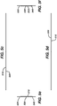
- Figs. 5a-5f depict a wound closure device comprising a three-part release liner in accordance with a further embodiment of the invention.
- Figs. 6a-6f depict a wound closure device comprising a three-part release liner in accordance with another embodiment of the invention.
- Figs. 7a-7f depict a wound closure device comprising a three-part release liner in accordance with a further embodiment of the invention.
- Figs. 8- 14 depict steps for the use of the device of this invention.
- FIG. 8 center section 130 of wound closure device 100 is removed by grasping and pulling either t' or t.
- Fig. 9 illustrates wound closure device 100 being grasped at first frame 120.
- Fig. 10 shows the device being positioned axially along a side of wound W of tissue T and contacting a first separated topical tissue surface TS 1 .
- FIG 11 depicts an alternate view of tissue surface TS 1 on one side of wound W being contacted by the adhesive containing side of wound closure strip 110 with left hand LH of a user and initially being pulled to approximate a second separated topical tissue surface TS 2 of wound W to the first separated topical tissue surface TS 1 of wound W by pulling first frame 120 with right hand RH of the user.
- Figure 12 shows second frame 140 being removed from wound closure strip 110 by left hand LH of the user and
- Fig. 13 shows first frame 120 being removed from wound closure strip 110 by right hand RH of the user.
- frame 140 may be removed and wound closure strip 110 may be further adhered to topical tissue surface TS 1 .
- This variation to the technique is useful when additional gripping of TS 1 is desired or needed prior to completing the wound approximation.
- Advantages of the methods, devices and systems of this invention include: clear visualization for placement of mesh 110 to approximate wound W by abutting the separate topical tissue surfaces of wound W; flexibility to reposition mesh 100 and adjust the approximation of wound W (i.e., the abutment of the separated topical tissue surfaces of the W) before mesh 110 is fully placed on the abutted topical tissue surfaces; ability to handle placement of mesh 110 without denigrating or minimizing denigration of the adhesive side of mesh 110; manipulation of mesh 110 is more stable during tissue approximation as frames 120 and 140 provide rigidity for mesh 110.
Abstract
Description
- This invention is concerned with devices for wound closure, particularly for skin closure of wounds formed by lacerations or surgical incisions.
- Wound closure tapes and topical adhesives provide an alternative to wound closure by staples and sutures. Among the advantages of using wound closure tapes or topical adhesives, and their combinations include less tissue trauma, improved cosmetic outcomes, and less pain compared with staples and sutures when treating skin closures.
-
US 2002/0193721 discloses a wound closure grip-like tape apparatus and methods of its use. Reference toFIG. 10 ofUS 2002/0193721 and the corresponding text of this publication shows how the grip tape is used to secure the wound ofFIG. 9 . In particular, paragraph 43 of the publication describes three techniques of wound closure reproduced in part as follows: "The first exemplary means of sealing the wound is to place WCGT ("Wound Closure Grid Tape") 100 on one side of the wound 90 with a slight bend along the axis between numbers 92 and 93 such that the other side 91 is tilted above the skin and thus will not adhere. With side 90 pressed in place and with the appropriate pressure applied, the WCGT is tugged with one hand while the other hand (or the thumb of the hand if being self-applied or with one hand) pushes the skin on the other side 91 into position, and then the WCGT is lowered into place. This handling can be done by grasping the WCGT at the edges where denigration of the adhesive is not as critical, or alternately by leaving the backing attached to the secondary side 91 while the first side is pressed into place 90. The second exemplary means to apply is to curve the WCGT upwards, or hold it in a curved position upwards along the longer axis shown, and position it starting at one end of the wound 92. Then, as previously, the wound is pressed together and the WCGT is pressed into place gradually along the length of the wound, going from one end 92 to the other 93. For small wounds, a third approach is to hold the WCGT by the edges and close the wound via pressures outside of the expected WCGT area, and then press the WCGT in place all at once." - In the forgoing description, denigration of the wound-contacting adhesive is a recognized problem since holding at least some of the underside of WCGT 100 is required particularly when side 90 of the wound is drawn toward side 91 of the wound. Thus from the forgoing description, it appears that wound closure tape only to has a single release liner.
-
US 2008/0302487 A1 describes a dispensing device configured to operate with an adhesive backed mesh and backing film for tissue bonding. The device prevents or eliminates distortion of the mesh prior to application to the wound sites and includes means for reducing or eliminating binding during use. The dispensing device is configured to operate in a "forward" mode (substrate to which mesh is applied passes beneath applicator after mesh is applied) to provide essentially an unobstructed view of the wound site during use. The backing film is a single strip that protects denigration of adhesive and self-adherence of the coiled adhesive-backed mesh. -
US2005/0182443A is directed to a tissue bonding article which includes a flexible material, an adhesive substance applied over at least a portion of a bottom side of the flexible material, and a polymerizable adhesive composition permeated throughout at least a portion of the flexible material. Although not specifically shown in the figures, a suitable backing or release material may also be used to cover the adhesive substances applied to the bottom side of the flexible material. Such backing materials are well known in the art for covering adhesives and can include, for example, paper, plastic, or the like. - There continues to be a need for improved devices and systems that use surgical tapes, topical adhesives and their combinations such as those provided by this invention.
- The invention is defined by the appended claims.
- Advantages of the invention include:
- 1) Minimization of adhesive transfer from the product to the user's fingers/gloves, therefore maximizing grip to tissue.
- 2) Due to the presence of release liner frames, ease of repositioning the wound closure strip once deployed on approximated wound edges.
- 3) Pressure sensitive adhesive is present on only the side that is intended to be in contact with tissue. So there is no accidental adherence of objects to the wound closure strip side not in contact with tissue.
- 4) Manipulation of the wound closure strip is stable during tissue approximation as the release liner frames provide sufficient rigidity.
- 5) Easy removal of the release liner central section with respect to the frames of the release liner.
-
-
Figs. 1a-1f depict a wound closure device comprising a three-part release liner in accordance with an embodiment of the invention. -
Figs. 1a'-1f' depict a wound closure device comprising a three-part release liner in accordance with an embodiment of the invention. -
Figs. 2a-2f depict a wound closure device comprising a three-part release liner in accordance with an embodiment of the invention. -
Figs. 3a-3f depict a wound closure device comprising a three-part release liner in accordance with an embodiment of the invention. -
Figs. 4a-4f depict a wound closure device comprising a three-part release liner in accordance with an embodiment of the invention. -
Figs. 5a-5f depict a wound closure device comprising a three-part release liner in accordance with an embodiment of the invention. -
Figs. 6a-6f depict a wound closure device comprising a three-part release liner in accordance with an embodiment of the invention. -
Figs. 7a-7f depict a wound closure device comprising a three-part release liner in accordance with an embodiment of the invention. -
Fig. 8 depicts a first step for use of the device in accordance with the invention. -
Fig. 9 depicts a second step for use of the device in accordance with the invention. -
Fig. 10 depicts a third step for use of the device in accordance with the invention. -
Fig. 11 depicts a fourth step for use of the device in accordance with the invention. -
Fig. 11' depicts a modification to the fourth and fifth steps for use of the device in accordance with the invention. -
Fig. 12 depicts a fifth step for use of the device in accordance with the invention. -
Fig. 13 depicts a sixth step for use of the device in accordance with the invention. -
Fig. 14 depicts a further step for use of the device in accordance with the invention. - A key aspect for the improved ease of use of wound closure devices of this invention lies in the three-part release liner assembly used in conjunction with a wound closure strip.
- Wound closure strips suitable for use in this invention comprise any suitable strip that is adaptable to close a wound. Preferably, the wound closure strip is porous and will allow a flowable, polymerizable adhesive to permeate the strip and to allow adequate bonding of the strip to a tissue surface being bonded.
- The wound closure strip comprises a wound facing side and a top side. The wound facing side further comprises an adhesive such as a pressure sensitive adhesive (PSA) applied over at least a portion of the wound facing side. The PSA is useful for initially approximating the wound. The wound closure strip is preferably porous. By "porous" is meant herein either that the bulk of the wound closure strip has pores, such that subsequently applied polymerizable adhesive composition is soaked up or absorbed by the bulk material, or that the bulk of the wound closure strip has voids (like a net or screen), such that the subsequently applied polymerizable adhesive composition passes directly through the bulk material, with or without being soaked up or absorbed by the bulk material. For example, in the case of textile materials, "porous" is generally used to mean that the applied adhesive composition permeates and passes through interstices between the fibers, but does not necessarily pass into and through the fibers themselves. Preferably the wound closure strip is a mesh.
- Such porosity (or other properties such as hydrophobicity or hydrophilicity) will also allow a polymerization initiator or rate modifier to be loaded in or on the wound closure strip prior to use, to initiate the subsequently applied polymerizable adhesive composition. Such porosity will also preferably allow air and fluid to pass through the wound closure strip, either through pores per se, or through voids in the bulk material. Depending upon the degree of porosity and/or the size of the openings, such porosity of the mesh or ability of air and fluid to permeate through the mesh may be tailored either to remain after a final composite material is formed, or to be absent therefrom. The wound closure strip is also preferably non-toxic, as it is intended to be used cover a wound, such as on biological tissues. As such, the wound closure strip should be biologically compatible with the desired substrate (such as tissue, skin, organ, or the like), and is preferably a material that is governmentally approved or generally regarded as safe for the desired purpose. By way of example, suitable wound closure strips are mesh materials and are disclosed in United States Patent Applications
2006/0009099 and2005/0182443 , incorporated herein by reference in their entirety. - The wound closure strip may be a textile or mesh/web material. Suitable textile materials may be formed of either synthetic or natural materials. Such textile material may be formed of either woven or non-woven fabrics or materials. The wound closure strip may be, for example, any suitable polymeric film, plastic foam (including open celled foam), a woven fabric, knitted fabric, a non-woven fabric, mixture thereof, or the like. In particular, suitable wound closure strips may thus be prepared, for example, from nylon, a polyolefin film, such as polyethylene, polypropylene, ethylene propylene copolymers, and ethylene butylene copolymers, polyurethanes, polyurethane foams, polystyrenes, plasticized polyvinylchlorides, polyesters, polyamides, polylactic acid, polyglycolic acid, polycaprolactone, copolymer mixtures of the above, and cotton. Suitable specific examples include, for example, nylon, polyethylene, polypropylene, ethylene propylene copolymers, ethylene butylene copolymers, polyurethane, polystyrene, plasticized polyvinylchloride, polyester, polyamide, cotton, polytetrafluoroethylene (PTFE), biovascular material, collagen, Gore-Tex®, DACRON®, etc.
- The wound closure strip may be formed of a synthetic, semi-synthetic, or natural organic material. Thus, for example, the mesh may be formed of a synthetic or natural polymer material, but not from a material such as metal (such as silver, steel or the like) or glass or ceramic. The wound closure strip may be either biodegradable, or not biodegradable. The wound closure strip is preferably resistant to tearing.
- The thickness of the wound closure strip may be from about 0.1 mm to about 80 mm. In another embodiment, the thickness of the wound closure strip is from about 0.5 mm to about 20 mm, preferably from about 0.7 mm to about 10 mm, most preferably from about 1 mm to about 5 mm.
- The wound closure strip may be from about 2 cm to about 40 cm, preferably from about 10 to about 30 cm, most preferably 25 cm in length. The strip may be from 0.1 to about 8 cm, preferably from about 2 to 6 cm, more preferably about 4 cm in width.
- The wound closure strip may be selected to be elastic or have some memory effect. In such embodiments, the elastic properties of the mesh may desirably provide a degree of pressure or stress at the application site, for example, to maintain wound edge approximation. Likewise, in embodiments where such additional degree of pressure or stress at the application site is not desired, the mesh may be selected to have less or no elasticity.
- The wound closure strip may be either biodegradable, or not biodegradable. By "biodegradable" is meant that the mesh biodegrades over time in vivo, such that it does not require physical removal of the mesh after a set period of time. Thus, for example, a biodegradable mesh is one that, in the in vivo environment, will biodegrade over a period of from about one week to about five years. A nonbiodegradable material is one that does not biodegrade in an in vivo environment within about five years. Such a nonbiodegradable material thus would require physical removal of the wound closure strip at a desired time, rather than slowly deteriorating over time or may slough off naturally from the tissue.
- The wound closure strip preferably includes one or more chemical materials located in or on it. For example, one or more chemical substances may be dispersed in or on the wound closure strip, such as being chemically bound, physically bound, absorbed, or adsorbed to it. Thus, for example, the wound closure strip preferably includes at least a polymerization initiator or rate modifier, and may optionally include one or more bioactive materials. As desired, the one or more chemical substances may be either immobilized in or on the wound closure strip, for example, so that it has a desired effect but is not detached from the wound closure strip during use.
- For example, a polymerization initiator or rate modifier may be loaded in or on the wound closure strip so that the initiator or rate modifier provides the desired initiation or rate modification effect to a subsequently applied polymerizable adhesive composition. The polymerization initiator or rate modifier may be immobilized in or on the wound closure strip, so that the initiator or rate modifier does not become detached from the wound closure strip and its residues are dispersed in the resultant polymeric material. Alternatively, for example, the polymerization initiator or rate modifier may be initially attached to the wound closure strip, but only in such a manner that it becomes mobilized or solubilized by a subsequently applied polymerizable adhesive composition and dispersed in the resultant polymeric material.
- If desired, a combination of chemical substances may also be provided in or on the wound closure strip, to provide multiple effects. For example, as described above, a first chemical species (such as a polymerization initiator or rate modifier) may be immobilized in or on the wound closure strip, while a second, different chemical species (such as a bioactive material) may be detachably attached to the wound closure strip. Other combinations of chemical species and resultant effects are also envisioned.
- The chemical substance may be applied in a uniform manner to the wound closure strip, such that there is a substantially uniform concentration of the chemical substance across the wound closure strip. Alternatively, the chemical substance may be applied such that a concentration gradient exists across or through the wound closure strip. For example, a greater or smaller concentration of the chemical substance could exist at the center or edges of the wound closure strip, or a greater or smaller concentration of the chemical substance could be applied on one side of the wound closure strip as compared to an opposite side. Further, the chemical substance may be applied in a uniform manner to the wound closure strip, or it may be applied in a non-uniform random or patterned manner (such as lines, dots, concentric circles, or the like). The chemical substances may also be on, beneath, or in the adhesive layer applied to the wound closure strip.
- When present in or on the wound closure strip, the chemical substances (i.e., polymerization initiator, rate modifier, and/or bioactive materials, or other additives), may be incorporated in or on the wound closure strip in any suitable manner. For example, the chemical substance may be wound closure strip added to the wound closure strip by contacting the wound closure strip with a solution, mixture, or the like including the chemical substances. The chemical substance may be added to the wound closure strip, for example, by dipping, spraying, roll coating, gravure coating, brushing, vapor deposition, or the like. Alternatively, the chemical substance may be incorporated into or onto the wound closure strip during manufacture of the wound closure strip, such as during molding, knitting/weaving, scouring, tenting, plaiting or other processing or the like of the wound closure strip.
- Other chemical substances that may be present in or on the wound closure strip include, but are not limited to, any suitable and preferably compatible additive that enhances performance of the composite structure. Such additional chemical substances may be bioactive or non-bioactive. Suitable other chemical substances thus include, but are not limited to, colorants (such as inks, dyes and pigments), scents, protective coatings that do not chemically detach, temperature sensitive agents, drugs, wound-healing agents, anti-microbial agents and the like.
- The polymerization initiator or rate modifier loaded in or on the wound closure strip may provide a number of advantages for example, the tailoring of the setting or polymerization time of the applied polymerizable adhesive composition. For example, the type and/or concentration of initiator that is applied to the wound closure strip may be selected so as to provide faster or slower polymerization time. The concentration of polymerization initiator or rate modifier may be increased to provide a faster polymerization time, or may be decreased to provide a slower polymerization time.
- Because the polymerization initiator or rate modifier is loaded directly in or on the wound closure strip, it is not necessary to mix the polymerizable adhesive composition with a polymerization initiator or rate modifier prior to application. This may allow a longer working time, where the polymerizable monomer composition may be more precisely and carefully applied over a longer period of time.
- Such suitable initiators are known in the art and are described, for example, in
U.S. Pat. Nos. 5,928,611 and6,620,846 , both incorporated herein by reference in their entireties, andU.S. Patent Application No. 2002/0037310 , also incorporated herein by reference in its entirety. Quaternary ammonium chloride and bromide salts useful as polymerization initiators are particularly suitable. By way of example, quaternary ammonium salts such as domiphen bromide, butyrylcholine chloride, benzalkonium bromide, acetyl choline chloride, among others, may be used. - Benzalkonium or benzyltrialkyl ammonium halides such as benzyltrialkyl ammonium chloride may be used. When used, the benzalkonium halide may be benzalkonium halide in its unpurified state, which comprises a mixture of varying chain-length compounds, or it can be any suitable purified compound including those having a chain length of from about 12 to about 18 carbon atoms, including but not limited to C12, C13, C14, C15, C16, C17, and C18 compounds. By way of example, the initiator may be a quaternary ammonium chloride salt such as benzyltrialkyl ammonium chloride (BTAC).
- Other initiators or accelerators may also be selected by one of ordinary skill in the art without undue experimentation. Such suitable initiators or accelerators may include, but are not limited to, detergent compositions; surfactants: e.g., nonionic surfactants such as polysorbate 20 (e.g., Tween 20™ from ICI Americas), polysorbate 80 (e.g., Tween 80™ from ICI Americas) and poloxamers, cationic surfactants such as tetrabutylammonium bromide, anionic surfactants such as sodium tetradecyl sulfate, and amphoteric or zwitterionic surfactants such as dodecyldimethyl(3-sulfopropyl)ammonium hydroxide, inner salt; amines, imines and amides, such as imidazole, arginine and povidine; phosphines, phosphites and phosphonium salts, such as triphenylphosphine and triethyl phosphite; alcohols such as ethylene glycol, methyl gallate; tannins; inorganic bases and salts, such as sodium bisulfite, calcium sulfate and sodium silicate; sulfur compounds such as thiourea and polysulfides; polymeric cyclic ethers such as monensin, nonactin, crown ethers, calixarenes and polymeric-epoxides; cyclic and acyclic carbonates, such as diethyl carbonate; phase transfer catalysts such as Aliquat 336; organometallics such as cobalt naphthenate and manganese acetylacetonate; and radical initiators or accelerators and radicals, such as di-t-butyl peroxide and azobisisobutyronitrile.
- Mixtures of two or more, such as three, four, or more, initiators or accelerators may be used. A combination of multiple initiators or accelerators may be beneficial, for example, to tailor the initiator of the polymerizable monomer species. For example, where a blend of monomers is used, a blend of initiators may provide superior results to a single initiator. For example, the blend of initiators can provide one initiator that preferentially initiates one monomer, and a second initiator that preferentially initiates the other monomer, or can provide initiation rates to help ensure that both monomer species are initiated at equivalent, or desired non-equivalent, rates. In this manner, a blend of initiators can help minimize the amount of initiator necessary. Furthermore, a blend of initiators may enhance the polymerization reaction kinetics. The polymerization initiator, accelerator, rate-modifier, and/or cross-linking agent may be incorporated into the mesh using impregnation methods known in the art.
- The three-part release liner assembly is a backing film comprising multiple, individually peelable sections, most preferably in three sections, each section may be of same dimensions, more preferably, the sections in the outer portion may be of identical or similar dimensions and shapes.
- The material for the invention's release liner assembly may be any suitable backing or release material used to cover the adhesive substances applied to the wound facing side of the wound closure strip. Such backing materials are well known in the art for covering adhesives and can include, for example, paper, plastic, or the like. By way of example, the release liner assembly may be a silicone treated material. Preferably, the release liner assembly is of a material that prevents or eliminates the wound closure strip from sticking to itself.
- The wound closure strip and the release liner assembly may overlap 100% (i.e., be coextensive), but preferably allowing a release liner exposed margin of 0.1 to 1.5 cm, more preferably about 1.0 cm of release liner margin. By "release liner margin" with respect to width, it is intended to mean that the release liner assembly has a width which is such that it exceeds the strip width so that there is a margin on the liner assembly on one or both sides which is exposed according to the aforementioned margin. In addition, or alternatively, the strip and the release liner assembly may overlap lengthwise allowing paper lining exposure sections of 0.2 cm to 8 cm, preferably of about 0.5 cm to 5 cm, and more preferred of about 1.5 cm. Again, by "release liner margin" with respect to length, it is intended to mean that the release liner assembly has a length which is such that it exceeds the strip length so that there is a margin on the liner assembly on one or both ends which is exposed according to the aforementioned margin.
- The method of wound closure or tissue bonding herein disclosed includes a polymerizable adhesive composition applied over the wound closure strip after the wound closure strip is applied to a tissue or wound site. The polymerizable adhesive composition may comprise a polymerizable monomeric adhesive. In embodiments, the polymerizable adhesive composition comprises a polymerizable 1,1-disubstituted ethylene monomer formulation. In embodiments, the polymerizable adhesive composition comprises a cyanoacrylate formulation. In embodiments, synthetic polymerizable adhesive materials such as polyurethane, polyethylene glycol, acrylates, glutaraldehyde and biologically based adhesives may be used.
- Suitable α-cyanoacrylate monomers which may be used, alone or in combination, include alkyl α-cyanoacrylates such as 2-octyl cyanoacrylate; dodecyl cyanoacrylate; 2-ethylhexyl cyanoacrylate; butyl cyanoacrylate such as n-butyl cyanoacrylate; ethyl cyanoacrylate; methyl cyanoacrylate or other α-cyanoacrylate monomers such as methoxyethyl cyanoacrylate; 2-ethoxyethyl cyanoacrylate; 3-methoxybutyl cyanoacrylate; 2-butoxyethyl cyanoacrylate; 2-isopropoxyethyl cyanoacrylate; and 1-methoxy-2-propyl cyanoacrylate. In embodiments, the monomers are ethyl, n-butyl, or 2-octyl α-cyanoacrylate. Other cyanoacrylate monomers which may be used include alkyl ester cyanoacrylates, such as those prepared by the Knoevenagel reaction of an alkyl cyanoacetate, or an alkyl ester cyanoacetate, with paraformaldehyde, subsequent thermal cracking of the resultant oligomer and distillation.
- The wound closure device herein disclosed may be provided in a kit comprising additional components. The kit may comprise at least one mesh strip as herein described, and one or more containers of polymerizable adhesive composition. The different components or groups of components may be sterilized in separate containers before packaging the components or groups of components within a kit, and thereafter sterilizing the kit as disclosed in co-assigned
U.S. Pregrant Patent Publication No. 2004/0120849 , incorporated herein by reference in its entirety. - The adhesive substance used in the mesh may, for example, be any suitable adhesive substance. Preferably, the adhesive substance is a medical grade adhesive, such as acrylic based pressure sensitive adhesives (PSAs), rubber based pressure sensitive adhesives, silicone pressure sensitive adhesives, mixtures thereof, or the like. It is preferred that the adhesive substance be different from the polymerizable adhesive composition. Thus, for example, it is preferred that while the polymerizable adhesive composition can be, for example, a polymerizable monomeric adhesive composition, the adhesive substance is a material that is not a polymerizable adhesive composition, such as a pressure sensitive adhesive.
- Suitable rubber based PSAs include, but are not limited to, those taught in
U.S. Pat. No. 5,705,551 and inU.S. Pat. No. 4,080,348 , the disclosures of which are hereby incorporated by reference. Examples of polymeric rubber bases include one or more of styrene-isoprene-styrene polymers, styrene-olefin-styrene polymers including styrene-ethylene/propylene-styrene polymers, polyisobutylene, styrene-butadiene-styrene polymers, polyisoprene, polybutadiene, natural rubber, silicone rubber, acrylonitrile rubber, nitrile rubber, polyurethane rubber, polyisobutylene rubber, butyl rubber, halobutyl rubber including bromobutyl rubber, butadiene-acrylonitrile rubber, polychloroprene, and styrene-butadiene rubber. - A particularly useful rubber based adhesive is that which has a thermoplastic elastomeric component and a resin component. The thermoplastic elastomeric component contains about 55-85 parts of a simple A-B block copolymer wherein the A-blocks are derived from styrene homologs and the B-blocks are derived from isoprene, and about 15-45 parts of a linear or radical A-B-A block copolymer wherein the A-blocks are derived from styrene or styrene homologs and the B-blocks are derived from conjugated dienes or lower alkenes, the A-blocks in the A-B block copolymer constituting about 10-18 percent by weight of the A-B copolymer and the total A-B and A-B-A copolymers containing about 20 percent or less styrene. The resin component consists of essentially of tackifier resins for the elastomeric component. In general any compatible conventional tackifier resin or mixture of such resins may be used. These include hydrocarbon resins, rosin and rosin derivatives, polyterpenes and other tackifiers. The adhesive substance may contain about 20-300 parts of the resin component per one hundred parts by weight of the thermoplastic elastomeric component. One such rubber based adhesive substance is commercially available from Ato Findley under the trade name HM3210.
- Useful acrylic based PSAs include, but are not limited to, those taught in
U.S. Pat. No. 5,947,917 andU.S. Pat. No. 5,164,444 (acrylic emulsion),U.S. Pat. No. 5,623,011 (tackified acrylic emulsion). It can also be radiation curable mixture of monomers with initiators and other ingredients such as those taught inU.S. Pat. No. 5,232,958 (UV cured acrylic) andU.S. Pat. No. 5,232,958 (EB cured). The disclosures of these patents are hereby incorporated by reference. - It is contemplated that any acrylic based polymer capable of forming an adhesive layer with sufficient tack to adhere to the wound closure strip, the backing film or to a substrate, and with acceptable adhesion to skin, may be used. In certain embodiments, the acrylic polymers for the pressure-sensitive adhesive layers include those formed from polymerization of at least one alkyl acrylate monomer or methacrylate, an unsaturated carboxylic acid and optionally a vinyl lactam. Examples of suitable alkyl acrylate or methacrylate esters include, but are not limited to, butyl acrylate, ethyl acrylate, 2-ethylhexyl acrylate, isooctyl acrylate, isononyl acrylate, isodecyl acrylate, methyl acrylate, methylbutyl acrylate, 4-methyl-2-pentyl acrylate, sec-butyl acrylate, ethyl methacrylate, isodecyl methacrylate, methyl methacrylate, and the like, and mixtures thereof. Examples of suitable ethylenically unsaturated carboxylic acids include, but are not limited to, acrylic acid, methacrylic acid, fumaric acid, itaconic acid, and the like, and mixtures thereof. A preferred ethylenically unsaturated carboxylic acid monomer is acrylic acid. Examples of suitable vinyl lactams include, but are not limited to, N-vinyl caprolactam, 1-vinyl-2-piperidone, 1-vinyl-5-methyl-2-pyrrolidone-, vinyl pyrrolidone, and the like, and mixtures thereof.
- Useful silicone pressure sensitive adhesives include those commercially available from Dow Corning Corp., Medical Products and those available from General Electric. Examples of silicone adhesives available from Dow Corning include those sold under the trademarks BIO-PSA X7-3027, BIO-PSA X7-4919, BIO-PSA X7-2685, BIO-PSA X7-3122 and BIO-PSA X7-4502. Additional examples of silicone pressure sensitive adhesives are described in
U.S. Pat. Nos. 4,591,622 ,4,584,355 ,4,585,836 and4,655,767 , the entire disclosures of which are incorporated herein by reference. - The adhesive substance may also include one or more tackifiers, plasticizers, antioxidants, cutting agents such as waxes, and surfactants. Other optional materials that may be added to the adhesive substance layer in minor amounts (typically less than about 25% by weight of the elastomeric phase) include pH controllers, medicaments, bactericides, growth factors, wound healing components such as collagen, antioxidants, deodorants, perfumes, antimicrobials and fungicides.
-
Figs. 1a-1f depict woundclosure device 100 having an overall length 1 and overall width w and comprising a three-partrelease liner assembly 150 in accordance with one embodiment of the invention. In particular,Fig. 1a is a front view ofdevice 100 comprising amesh 110 having perimeter p and a release orbacking assembly 150 having perimeter p' comprisingfirst frame 120,central section 130 having pull tabs t and t', andsecond frame 140. - In certain embodiments, the
release liner assembly 150 may be a release liner assembly. By "central" section, it is intended to mean that this section merely resides between thefirst frame 120 andsecond frame 140, rather than necessarily being centrally located. In a particular more limiting embodiment, thesection 130 may be centrally located with respect to thefirst frame 120 andsecond frame 140. While two tabs t' and t" are shown, it will be appreciated that in certain embodiments only a single tab t' may be present at one end of therelease assembly 150. - Distances a and a' represent the distances of the release liner assembly perimeter p' to mesh 110 perimeter p of the left hand and right hand sides of
device 100, respectively. Distances b and b' represent the distances from the release liner assembly perimeter p' to mesh 110 perimeter p of the top and bottom sides ofdevice 100, respectively. Distances c and c' represent the width offirst frame 120 andsecond frame 140, respectively, and coinciding with the width ofcentral section 130 at dimension d. -
Fig. 1b is a rear view of the device.Figs. 1c and 1d are top and bottom views ofdevice 100, respectively.Figs. 1e and 1f are left-side and right-side views, respectively ofdevice 100. - Many embodiments are evident for
device 100 depending on the specific dimensions one skilled in the art may select and adapt to treat wounds or incisions of various sizes and shapes. - For example, referring to
Fig. 1a , it is envisioned thatmesh 110 perimeter p can be coextensive withdevice 100 perimeter p', partially coextensive or not be coextensive as indicated by the following discussion. -
Device 100 may be of any length l' and width w' that permits the user to effectively apply to close a wound or incision. For many applications, length l' will typically range from about 2 cm to about 40 cm, preferably from about 10 cm to 30 about cm, and most preferably about 25 cm. Width w' will typically range from about 1 cm to about 15 cm, preferably from about 2 to about 10 cm, and most preferably about 6 cm. -
Wound closure strip 110 may be of any length 1 and width w that permits the user to effectively apply to close a wound or incision. For many applications, length 1 will typically range from about 2 cm to about 40 cm, preferably from about 10 cm to about 30 cm, and most preferably about 25 cm. Width w' will typically range from about 0.1 cm to about 8 cm, preferably from about 2 cm to about 6 cm, and most preferably about 4 cm. - Again referring to
Fig. 1a , the distances a and a' may be the same or different and range from 0.0 cm to about 8 cm, preferably from about 0.5 cm to about 5 cm, and most preferably about 1.5 cm. It is within the foregoing rangesdevice 100 is conveniently handled. - In certain circumstances, for example (but not limited to) when the dimensions of a or a' is 0.0 cm, either one or both pull tabs, t or t', extend or protrude beyond the perimeter p', for example beyond one or both ends of the
first frame 120 andsecond frame 140. Extended tabs t" and t'" are shown inFigs. 1a' to 1d' (see below). In this way, the user is able to more easily removecenter section 130 fromdevice 100 since the edge of one or both tabs t", t'" of thecenter section 130 protrude away from the corresponding edge of thefirst frame 120 andsecond frame 140 making each tab t" , t"' easier to grip for removal. Of course, in an embodiment in which only one pull tab t'' is present, then only this tab may protrude beyond its corresponding one end of thefirst frame 120 andsecond frame 140. - Dimensions b and b' may be the same or different and range from 0.0 cm to about 2.5 cm, preferably from about 0.5 cm to about 1.5 cm, and most preferably about 1.0 cm. It is within the foregoing ranges that the margins of
frames wound closure strip 110 are defined. Dimensions b and b' provide sufficient margin for manipulation ofwound closure strip 110 during the approximation of a wound in a manner that lessens the tendency for the adhesive (and other additives that may be present on or in wound closure strip, such as initiators) to become denigrated. While it is preferred that dimensions b and b' are the same, it is envisioned that there may be some applications on the human anatomy where it is desirable to have one of margins b and b' narrower or wider than the other. - Dimensions c and c' may be the same or different and range from 0.1 cm to about 3.0 cm, preferably from about 0.2 cm to about 2.0 cm, and most preferably about 1.5 cm. It is within the foregoing ranges that frames 120 and 140 provide sufficient rigidity for manipulation of
wound closure strip 110 during the approximation of a wound. While it is preferred that dimensions c and c' are the same, it is envisioned that there may be some applications on the human anatomy where it is desirable to have one offrames - Dimension d relates to the width of
wound closure strip 110 that is suitable for the user to position and/or repositionwound closure strip 110 for the initial approximation of the separated topical tissue surfaces of a wound. Dimension d ranges from about 1.0 cm to about 8.0 cm, preferably from about 2.0 cm to about 6.0 cm, and most preferably about 3.0 cm. - For treatment of surgical wound incisions of about 10 cm to about 20 cm, a preferred embodiment of
device 100 is for an overall length l' of about 25 cm and overall width w' of about 8 cm, wound closure strip of overall length 1 of about 22 cm and overall width w of about 4 cm with dimensions a and a' equal and about 1.5 cm, dimensions b and b' equal and about 1.0 cm, dimensions c and c' equal and about 1.5 cm, and dimension d about 3 cm. It would be appreciated by one of skill in the art thatdevice 100 may be cut or trimmed to size for wounds within the above identified range. In practice, it is desirable to have woundclosure strip 110 extend approximately at least 0.3 cm, preferably 1 cm from the longitudinal ends of the wound or incision site. -
Figs. 1a'-1f' depict a wound closure device comprising a three-part release liner in accordance with another embodiment of the invention. This embodiment depicts a variation of the device shown inFigs. 1a - 1f wherein tabs t" and t"' are shown to project or extend beyond the general perimeter p' ofrelease liner assembly 150, for example beyond one or both ends of thefirst frame 120 andsecond frame 130. This embodiment is useful for more easily removingcentral section 130. For example this is particularly advantageous if there is little or no margin between wound closure strip perimeter p and release liner assembly perimeter p', although it is advantageous even when a larger margin also exists. Of course, one example of such an instance would be when perimeters p and p' are coextensive with each other, except of course, for the protrusions of tabs t" and t"'. In general with the protruding tabs t", t"', the user is able to more easily removecenter section 130 fromdevice 100 since the edge of one or both tabs t", t"' of thecenter section 130 protrude away from the corresponding edge of thefirst frame 120 andsecond frame 140 making each tab t", t"' easier to grip for removal. Of course, in an embodiment in which only one pull tab t" is present, then only this tab may protrude beyond its corresponding one end of thefirst frame 120 andsecond frame 140. - Each tab may extend beyond a perimeter of the first frame and/or second frame in a direction substantially coincident with a longitudinal axis of the release assembly. The at least one tab may protrude beyond the perimeter of the first frame and/or second frame by an amount which is at least 0.05 cm, 0.1 cm, 0.2 cm, 0.3 cm, 0.4 cm, 0.5 cm, 1 cm, 1.5 cm, 2 cm, or 5 cm. The central section may be joined to the first frame and/or second frame by a frangible connection which is adapted to break upon pulling of the tab with respect to the first and/or second frame. Each tab may have a shape which is substantially one of the following: triangular, elliptical, square, rectangular, pentagonal, and hexagonal.
- As a point of clarity, the device illustrations of
Figs. 1a'-1f' toFigs. 7a-7f , inclusive, depict variations in the design ofcentral section 130 ofFigs. 1a-1f . As such, all previously defined parameters described forFigs. 1a-1f apply and have the same meaning. The numbering of the corresponding elements of the variously depicted embodiments for the devices follow the same numbering convention as inFigs. 1a-1f and only differ in that the numbering corresponds to series numbering specific to each set of illustrations (e.g., 200 series numbering for elements ofFigs. 2a-2f , 300 series numbering for elements ofFigs. 3a-3f , etc.) Therefore further detailed description is not provided as one skilled in the art would appreciate and understand the commonality and defined meaning of the elements and dimensions described therein. -
Figs. 2a-2f depict a wound closure device comprising a three-part release liner in accordance with another embodiment of the invention. -
Figs. 3a-3f depict a wound closure device comprising a three-part release liner in accordance with a further embodiment of the invention. -
Figs. 4a-4f depict a wound closure device comprising a three-part release liner in accordance with another embodiment of the invention. -
Figs. 5a-5f depict a wound closure device comprising a three-part release liner in accordance with a further embodiment of the invention. -
Figs. 6a-6f depict a wound closure device comprising a three-part release liner in accordance with another embodiment of the invention. -
Figs. 7a-7f depict a wound closure device comprising a three-part release liner in accordance with a further embodiment of the invention. -
Figs. 8- 14 depict steps for the use of the device of this invention. - In particular, once a suitable wound has been identified for use of the invention's device and referring to
Fig. 8 ,center section 130 ofwound closure device 100 is removed by grasping and pulling either t' or t. Next,Fig. 9 illustrates woundclosure device 100 being grasped atfirst frame 120. Subsequently,Fig. 10 shows the device being positioned axially along a side of wound W of tissue T and contacting a first separated topical tissue surface TS1.Fig. 11 depicts an alternate view of tissue surface TS1 on one side of wound W being contacted by the adhesive containing side ofwound closure strip 110 with left hand LH of a user and initially being pulled to approximate a second separated topical tissue surface TS2 of wound W to the first separated topical tissue surface TS1 of wound W by pullingfirst frame 120 with right hand RH of the user.Figure 12 showssecond frame 140 being removed fromwound closure strip 110 by left hand LH of the user andFig. 13 showsfirst frame 120 being removed fromwound closure strip 110 by right hand RH of the user. Once the bothframes applicator 800 which permeates woundclosure strip 100 to formfilm 810. - It would be understood by one of skill in the art that in the practice of this afore described method, once
central section 130 of the release liner assembly is removed, the selection of whether the user chooses to grasp or remove thefirst frame 120 orsecond frame 140 is immaterial to the practice of this invention provided that the subsequent steps of the method used accomplishes closure of the wound. - Furthermore, as a modification to the above method, and referring to
Fig. 11' , prior to performing the approximation of topical tissue surface TS1 to topical tissue surface TS2,frame 140 may be removed and woundclosure strip 110 may be further adhered to topical tissue surface TS1. This variation to the technique is useful when additional gripping of TS1 is desired or needed prior to completing the wound approximation. - Advantages of the methods, devices and systems of this invention include: clear visualization for placement of
mesh 110 to approximate wound W by abutting the separate topical tissue surfaces of wound W; flexibility to repositionmesh 100 and adjust the approximation of wound W (i.e., the abutment of the separated topical tissue surfaces of the W) beforemesh 110 is fully placed on the abutted topical tissue surfaces; ability to handle placement ofmesh 110 without denigrating or minimizing denigration of the adhesive side ofmesh 110; manipulation ofmesh 110 is more stable during tissue approximation asframes mesh 110. - It should be understood that the foregoing disclosure and description of the present invention are illustrative and explanatory thereof and various changes in the size, shape and materials as well as in the description of the preferred embodiment may be made without departing from the spirit of the invention.
-
- 1. A wound closure device comprising:
- a wound closure strip having a wound facing side and a top side, the wound facing side comprising an adhesive applied over at least a portion of the wound facing side;
- a release liner assembly detachably adhered to the strip by the adhesive, the release liner assembly comprising a first frame, a central section, and a second frame;
- wherein the central section of the release liner assembly comprises at least one tab located at an edge of the release liner assembly; and
- wherein the at least one tab protrudes beyond a perimeter of the first frame and/or second frame at the edge of the release liner assembly.
- 2. The device of embodiment 1, wherein the wound closure strip comprises a mesh.
- 3. The device of embodiment 2, wherein the mesh has an outer perimeter and the release liner assembly has an outer perimeter wherein at least a portion of the outer perimeter of the mesh lies within the outer perimeter of the release liner assembly.
- 4. The device of embodiment 3, wherein the entirety of outer perimeter of the mesh lies within the outer perimeter of the release liner assembly.
- 5. The device of embodiment 3, wherein the outer perimeter of the mesh and the outer perimeter of the release liner assembly are coextensive.
- 6. The device of embodiment 5, wherein the mesh further comprises a longitudinal axis and the release liner assembly further comprises a longitudinal axis and wherein a further portion of the central section of the release liner assembly extends beyond the outer perimeter of the mesh along the mesh's longitudinal axis.
- 7. The device of any one of the preceding embodiments, wherein the central section of the release liner assembly comprises at least two tabs located at opposing edges of the release liner assembly, wherein each tab protrudes beyond a perimeter of the first frame and/or second frame at its corresponding edge of the release liner assembly.
- 8. The device of any one of the preceding embodiments, wherein each tab extends beyond a perimeter of the first frame and/or second frame in a direction substantially coincident with a longitudinal axis of the release liner assembly.
- 9. The device of any one of the preceding embodiments, wherein the at least one tab protrudes beyond the perimeter of the first frame and/or second frame by an amount which is at least 0.05 cm, 0.1 cm, 0.2 cm, 0.3 cm, 0.4 cm, 0.5 cm, 1 cm, 1.5 cm, 2 cm, or 5 cm.
- 10. The device of any one of the preceding embodiments, wherein the central section is joined to the first frame and/or second frame by a frangible connection which is adapted to break upon pulling of the tab with respect to the first and/or second frame.
- 11. The device of any one of the preceding embodiments, wherein each tab has a shape which is substantially one of the following: triangular, elliptical, square, rectangular, pentagonal, and hexagonal.
Claims (9)
- A wound closure device comprising:a wound closure strip having a wound facing side and a top side, the wound facing side comprising an adhesive applied over at least a portion of the wound facing side;a release liner assembly detachably adhered to the strip by the adhesive, the release liner assembly being a backing film comprising a first frame, a central section, and a second frame which are individually peelable; andwherein the central section of the release liner assembly comprises at least one tab located at an edge of the release liner assembly.
- The device of claim 1, wherein the wound closure strip comprises a mesh.
- The device of claim 2, wherein the mesh has an outer perimeter and the release liner assembly has an outer perimeter wherein at least a portion of the outer perimeter of the mesh lies within the outer perimeter of the release liner assembly.
- The device of claim 3, wherein the entirety of outer perimeter of the mesh lies within the outer perimeter of the release liner assembly.
- The device of claim 3, wherein the outer perimeter of the mesh and the outer perimeter of the release liner assembly are coextensive.
- The device of claim 5, wherein the mesh further comprises a longitudinal axis and the release liner assembly further comprises a longitudinal axis and wherein a further portion of the central section of the release liner assembly extends beyond the outer perimeter of the mesh along the mesh's longitudinal axis.
- The device of any one of the preceding claims, wherein the central section of the release liner assembly comprises at least two tabs located at opposing edges of the release liner assembly.
- The device of any one of the preceding claims, wherein the central section is joined to the first frame and/or second frame by a frangible connection which is adapted to break upon pulling of the tab with respect to the first and/or second frame.
- The device of any one of the preceding claims, wherein each tab has a shape which is substantially one of the following: triangular, elliptical, square, rectangular, pentagonal, and hexagonal.
Priority Applications (2)
| Application Number | Priority Date | Filing Date | Title |
|---|---|---|---|
| EP22162039.6A EP4049638A1 (en) | 2015-09-24 | 2015-09-24 | Devices for wound closure |
| EP20167273.0A EP3695819B1 (en) | 2015-09-24 | 2015-09-24 | Devices for wound closure |
Applications Claiming Priority (3)
| Application Number | Priority Date | Filing Date | Title |
|---|---|---|---|
| PCT/US2015/051919 WO2017052549A1 (en) | 2015-09-24 | 2015-09-24 | Devices for wound closure |
| EP15782118.2A EP3352717B1 (en) | 2015-09-24 | 2015-09-24 | Devices for wound closure |
| EP20167273.0A EP3695819B1 (en) | 2015-09-24 | 2015-09-24 | Devices for wound closure |
Related Parent Applications (1)
| Application Number | Title | Priority Date | Filing Date |
|---|---|---|---|
| EP15782118.2A Division EP3352717B1 (en) | 2015-09-24 | 2015-09-24 | Devices for wound closure |
Related Child Applications (1)
| Application Number | Title | Priority Date | Filing Date |
|---|---|---|---|
| EP22162039.6A Division EP4049638A1 (en) | 2015-09-24 | 2015-09-24 | Devices for wound closure |
Publications (2)
| Publication Number | Publication Date |
|---|---|
| EP3695819A1 true EP3695819A1 (en) | 2020-08-19 |
| EP3695819B1 EP3695819B1 (en) | 2022-03-16 |
Family
ID=54337863
Family Applications (3)
| Application Number | Title | Priority Date | Filing Date |
|---|---|---|---|
| EP20167273.0A Active EP3695819B1 (en) | 2015-09-24 | 2015-09-24 | Devices for wound closure |
| EP15782118.2A Active EP3352717B1 (en) | 2015-09-24 | 2015-09-24 | Devices for wound closure |
| EP22162039.6A Pending EP4049638A1 (en) | 2015-09-24 | 2015-09-24 | Devices for wound closure |
Family Applications After (2)
| Application Number | Title | Priority Date | Filing Date |
|---|---|---|---|
| EP15782118.2A Active EP3352717B1 (en) | 2015-09-24 | 2015-09-24 | Devices for wound closure |
| EP22162039.6A Pending EP4049638A1 (en) | 2015-09-24 | 2015-09-24 | Devices for wound closure |
Country Status (11)
| Country | Link |
|---|---|
| EP (3) | EP3695819B1 (en) |
| JP (1) | JP6707631B2 (en) |
| KR (1) | KR102478701B1 (en) |
| CN (1) | CN108348357B (en) |
| AU (2) | AU2015409656B2 (en) |
| BR (1) | BR112018005880B1 (en) |
| CA (1) | CA2999832C (en) |
| HK (1) | HK1258273A1 (en) |
| MX (1) | MX2018003714A (en) |
| RU (1) | RU2719016C2 (en) |
| WO (1) | WO2017052549A1 (en) |
Families Citing this family (3)
| Publication number | Priority date | Publication date | Assignee | Title |
|---|---|---|---|---|
| CA3183064A1 (en) * | 2020-06-19 | 2021-12-23 | Michael Lebner | Tabbed and split dual liner |
| US20230372157A1 (en) * | 2022-05-20 | 2023-11-23 | Chemence Medical, Inc. | Wound closure devices, kits, and related methods |
| US20240009341A1 (en) * | 2022-07-07 | 2024-01-11 | Chemence Medical Inc. | Dressing, a kit comprising a dressing and a method of preparing a dressing |
Citations (19)
| Publication number | Priority date | Publication date | Assignee | Title |
|---|---|---|---|---|
| US4080348A (en) | 1976-05-18 | 1978-03-21 | Johnson & Johnson | Tacky adhesive |
| US4584355A (en) | 1984-10-29 | 1986-04-22 | Dow Corning Corporation | Silicone pressure-sensitive adhesive process and product with improved lap-shear stability-I |
| US4585836A (en) | 1984-10-29 | 1986-04-29 | Dow Corning Corporation | Silicone pressure-sensitive adhesive process and product with improved lap-shear stability-II |
| US4591622A (en) | 1984-10-29 | 1986-05-27 | Dow Corning Corporation | Silicone pressure-sensitive adhesive process and product thereof |
| US4655767A (en) | 1984-10-29 | 1987-04-07 | Dow Corning Corporation | Transdermal drug delivery devices with amine-resistant silicone adhesives |
| US5164444A (en) | 1989-08-14 | 1992-11-17 | Avery Dennison Corporation | Emulsion pressure-sensitive adhesive polymers exhibiting excellent room- and low-temperature performance |
| US5232958A (en) | 1988-12-28 | 1993-08-03 | Avery Dennison Corporation | Electron-beam cured emulsion pressure-sensitive adhesives |
| US5623011A (en) | 1994-08-12 | 1997-04-22 | Avery Dennison Corporation | Tackified emulsion pressure-sensitive adhesive |
| US5705551A (en) | 1991-12-06 | 1998-01-06 | Avery Dennison Corporation | Elastomeric pressure-sensitive adhesive compositions exhibiting good cutting performance |
| US5928611A (en) | 1995-06-07 | 1999-07-27 | Closure Medical Corporation | Impregnated applicator tip |
| US5947917A (en) | 1998-08-28 | 1999-09-07 | Avery Dennison Corporation | Adhesive bandage or tape |
| US20020037310A1 (en) | 2000-08-02 | 2002-03-28 | Closure Medical Corporation | Absorbable adhesive compositions |
| US20020193721A1 (en) | 2001-06-15 | 2002-12-19 | Vandruff Dean | Wound closure grid tape apparatus and method |
| US20040120849A1 (en) | 2002-12-23 | 2004-06-24 | Closure Medical Corporation | Sterilization of medical adhesive kits |
| US20040220505A1 (en) * | 2003-05-03 | 2004-11-04 | George Worthley | Dressing and a method for applying the same |
| US20050182443A1 (en) | 2004-02-18 | 2005-08-18 | Closure Medical Corporation | Adhesive-containing wound closure device and method |
| US20060009099A1 (en) | 2004-07-12 | 2006-01-12 | Closure Medical Corporation | Adhesive-containing wound closure device and method |
| US20060058721A1 (en) * | 2004-09-10 | 2006-03-16 | Michael Lebner | Modular wound dressing system |
| US20080302487A1 (en) | 2007-06-07 | 2008-12-11 | Closure Medical Corporation | Mesh dispenser |
Family Cites Families (21)
| Publication number | Priority date | Publication date | Assignee | Title |
|---|---|---|---|---|
| JPS6036563Y2 (en) * | 1982-02-15 | 1985-10-30 | 久光製薬株式会社 | Release paper structure of patch medicine |
| US5266371A (en) | 1988-08-11 | 1993-11-30 | Nitto Denko Corporation | Adhesive dressing sheet |
| US5088483A (en) * | 1988-11-04 | 1992-02-18 | Minnesota Mining And Manufacturing Co. | Adhesive frame bandage |
| JP2519222Y2 (en) * | 1989-10-09 | 1996-12-04 | ニチバン株式会社 | Patch |
| US5160315A (en) | 1991-04-05 | 1992-11-03 | Minnesota Mining And Manufacturing Company | Combined adhesive strip and transparent dressing delivery system |
| GB9225146D0 (en) * | 1992-12-01 | 1993-01-20 | Brightwake Ltd | Bandage |
| JP2596722Y2 (en) * | 1993-12-28 | 1999-06-21 | ニチバン株式会社 | Sticking material |
| WO1997025012A1 (en) * | 1996-01-12 | 1997-07-17 | Smith & Nephew Plc | Wound dressing |
| US20020019602A1 (en) | 2000-03-07 | 2002-02-14 | Geng Lisa Fernandez | Wound dressing |
| US6838589B2 (en) * | 2003-02-19 | 2005-01-04 | 3M Innovative Properties Company | Conformable wound dressing |
| US7888546B2 (en) * | 2003-07-03 | 2011-02-15 | Corium International, Inc. | Wound dressing, ingredient delivery device and IV hold-down, and method relating to same |
| CN101677870B (en) | 2007-06-25 | 2011-03-30 | 科洛普拉斯特公司 | An ostomy appliance with multiple release liners |
| TWM332470U (en) | 2007-09-13 | 2008-05-21 | hui-ru Xu | Pharmaceutical patch |
| TWM329426U (en) * | 2007-09-13 | 2008-04-01 | hui-ru Xu | Pharmacy patch |
| CA2704790C (en) * | 2007-11-22 | 2014-04-01 | Moelnlycke Health Care Ab | Film dressing with an improved grip tab |
| WO2010048480A1 (en) * | 2008-10-24 | 2010-04-29 | 3M Innovative Properties Company | Wound dressing |
| JP5412323B2 (en) * | 2010-02-26 | 2014-02-12 | 日東電工株式会社 | Patch preparation |
| JP2013106719A (en) * | 2011-11-18 | 2013-06-06 | Nitto Denko Corp | Stretch adhesive bandage |
| CN104619376A (en) | 2012-09-07 | 2015-05-13 | C·R·巴德股份有限公司 | Medical article securement systems |
| DE102012223399A1 (en) * | 2012-12-17 | 2014-06-18 | Paul Hartmann Ag | Cuttable wound dressing |
| EP2805698B1 (en) * | 2013-05-22 | 2018-04-04 | Adhex Technologies | Wound Dressing |
-
2015
- 2015-09-24 BR BR112018005880-7A patent/BR112018005880B1/en active IP Right Grant
- 2015-09-24 JP JP2018515463A patent/JP6707631B2/en active Active
- 2015-09-24 RU RU2018114895A patent/RU2719016C2/en active
- 2015-09-24 WO PCT/US2015/051919 patent/WO2017052549A1/en active Application Filing
- 2015-09-24 EP EP20167273.0A patent/EP3695819B1/en active Active
- 2015-09-24 CN CN201580083347.XA patent/CN108348357B/en active Active
- 2015-09-24 CA CA2999832A patent/CA2999832C/en active Active
- 2015-09-24 EP EP15782118.2A patent/EP3352717B1/en active Active
- 2015-09-24 MX MX2018003714A patent/MX2018003714A/en unknown
- 2015-09-24 KR KR1020187010828A patent/KR102478701B1/en active IP Right Grant
- 2015-09-24 AU AU2015409656A patent/AU2015409656B2/en active Active
- 2015-09-24 EP EP22162039.6A patent/EP4049638A1/en active Pending
-
2019
- 2019-01-15 HK HK19100637.8A patent/HK1258273A1/en unknown
-
2020
- 2020-11-02 AU AU2020264265A patent/AU2020264265B2/en active Active
Patent Citations (21)
| Publication number | Priority date | Publication date | Assignee | Title |
|---|---|---|---|---|
| US4080348A (en) | 1976-05-18 | 1978-03-21 | Johnson & Johnson | Tacky adhesive |
| US4584355A (en) | 1984-10-29 | 1986-04-22 | Dow Corning Corporation | Silicone pressure-sensitive adhesive process and product with improved lap-shear stability-I |
| US4585836A (en) | 1984-10-29 | 1986-04-29 | Dow Corning Corporation | Silicone pressure-sensitive adhesive process and product with improved lap-shear stability-II |
| US4591622A (en) | 1984-10-29 | 1986-05-27 | Dow Corning Corporation | Silicone pressure-sensitive adhesive process and product thereof |
| US4655767A (en) | 1984-10-29 | 1987-04-07 | Dow Corning Corporation | Transdermal drug delivery devices with amine-resistant silicone adhesives |
| US5232958A (en) | 1988-12-28 | 1993-08-03 | Avery Dennison Corporation | Electron-beam cured emulsion pressure-sensitive adhesives |
| US5164444C2 (en) | 1989-08-14 | 2001-10-16 | Avery Dennison Corp | Emulsion pressure-sensitive adhesive polymers exhibiting excellent room-and-low-temperature performance |
| US5164444A (en) | 1989-08-14 | 1992-11-17 | Avery Dennison Corporation | Emulsion pressure-sensitive adhesive polymers exhibiting excellent room- and low-temperature performance |
| US5705551A (en) | 1991-12-06 | 1998-01-06 | Avery Dennison Corporation | Elastomeric pressure-sensitive adhesive compositions exhibiting good cutting performance |
| US5623011A (en) | 1994-08-12 | 1997-04-22 | Avery Dennison Corporation | Tackified emulsion pressure-sensitive adhesive |
| US5928611A (en) | 1995-06-07 | 1999-07-27 | Closure Medical Corporation | Impregnated applicator tip |
| US5947917A (en) | 1998-08-28 | 1999-09-07 | Avery Dennison Corporation | Adhesive bandage or tape |
| US20020037310A1 (en) | 2000-08-02 | 2002-03-28 | Closure Medical Corporation | Absorbable adhesive compositions |
| US6620846B1 (en) | 2000-08-02 | 2003-09-16 | Closure Medical Corporation | Absorbable adhesive compositions |
| US20020193721A1 (en) | 2001-06-15 | 2002-12-19 | Vandruff Dean | Wound closure grid tape apparatus and method |
| US20040120849A1 (en) | 2002-12-23 | 2004-06-24 | Closure Medical Corporation | Sterilization of medical adhesive kits |
| US20040220505A1 (en) * | 2003-05-03 | 2004-11-04 | George Worthley | Dressing and a method for applying the same |
| US20050182443A1 (en) | 2004-02-18 | 2005-08-18 | Closure Medical Corporation | Adhesive-containing wound closure device and method |
| US20060009099A1 (en) | 2004-07-12 | 2006-01-12 | Closure Medical Corporation | Adhesive-containing wound closure device and method |
| US20060058721A1 (en) * | 2004-09-10 | 2006-03-16 | Michael Lebner | Modular wound dressing system |
| US20080302487A1 (en) | 2007-06-07 | 2008-12-11 | Closure Medical Corporation | Mesh dispenser |
Also Published As
| Publication number | Publication date |
|---|---|
| KR102478701B1 (en) | 2022-12-19 |
| MX2018003714A (en) | 2018-08-01 |
| WO2017052549A1 (en) | 2017-03-30 |
| CA2999832C (en) | 2023-05-16 |
| EP3695819B1 (en) | 2022-03-16 |
| CN108348357A (en) | 2018-07-31 |
| RU2719016C2 (en) | 2020-04-16 |
| JP6707631B2 (en) | 2020-06-10 |
| HK1258273A1 (en) | 2019-11-08 |
| CN113995459A (en) | 2022-02-01 |
| EP4049638A1 (en) | 2022-08-31 |
| AU2020264265B2 (en) | 2021-07-29 |
| AU2015409656A1 (en) | 2018-04-12 |
| RU2018114895A3 (en) | 2019-10-24 |
| CA2999832A1 (en) | 2017-03-30 |
| EP3352717B1 (en) | 2020-04-01 |
| CN108348357B (en) | 2021-09-03 |
| EP3352717A1 (en) | 2018-08-01 |
| BR112018005880B1 (en) | 2022-02-22 |
| BR112018005880A2 (en) | 2018-10-16 |
| AU2020264265A1 (en) | 2020-11-26 |
| AU2015409656B2 (en) | 2020-08-06 |
| JP2018529433A (en) | 2018-10-11 |
| KR20180059473A (en) | 2018-06-04 |
| RU2018114895A (en) | 2019-10-24 |
Similar Documents
| Publication | Publication Date | Title |
|---|---|---|
| US11679034B2 (en) | Methods and devices for skin closure | |
| US10470934B2 (en) | Methods and devices for skin closure | |
| US20160089145A1 (en) | Methods and devices for wound closure | |
| US10258335B2 (en) | Mesh dispenser | |
| AU2020264265B2 (en) | Devices for wound closure | |
| US20090270884A1 (en) | Mesh Dispensing Device Having a Closed Loop of Backing Film | |
| JP7051936B2 (en) | Wound closure device | |
| CN113995459B (en) | Device for wound closure |
Legal Events
| Date | Code | Title | Description |
|---|---|---|---|
| PUAI | Public reference made under article 153(3) epc to a published international application that has entered the european phase |
Free format text: ORIGINAL CODE: 0009012 |
|
| STAA | Information on the status of an ep patent application or granted ep patent |
Free format text: STATUS: THE APPLICATION HAS BEEN PUBLISHED |
|
| AC | Divisional application: reference to earlier application |
Ref document number: 3352717 Country of ref document: EP Kind code of ref document: P |
|
| AK | Designated contracting states |
Kind code of ref document: A1 Designated state(s): AL AT BE BG CH CY CZ DE DK EE ES FI FR GB GR HR HU IE IS IT LI LT LU LV MC MK MT NL NO PL PT RO RS SE SI SK SM TR |
|
| STAA | Information on the status of an ep patent application or granted ep patent |
Free format text: STATUS: REQUEST FOR EXAMINATION WAS MADE |
|
| 17P | Request for examination filed |
Effective date: 20210219 |
|
| RBV | Designated contracting states (corrected) |
Designated state(s): AL AT BE BG CH CY CZ DE DK EE ES FI FR GB GR HR HU IE IS IT LI LT LU LV MC MK MT NL NO PL PT RO RS SE SI SK SM TR |
|
| RAP3 | Party data changed (applicant data changed or rights of an application transferred) |
Owner name: ETHICON LLC |
|
| GRAP | Despatch of communication of intention to grant a patent |
Free format text: ORIGINAL CODE: EPIDOSNIGR1 |
|
| STAA | Information on the status of an ep patent application or granted ep patent |
Free format text: STATUS: GRANT OF PATENT IS INTENDED |
|
| INTG | Intention to grant announced |
Effective date: 20211011 |
|
| RIN1 | Information on inventor provided before grant (corrected) |
Inventor name: QUINTERO, JULIAN A. |
|
| GRAS | Grant fee paid |
Free format text: ORIGINAL CODE: EPIDOSNIGR3 |
|
| GRAA | (expected) grant |
Free format text: ORIGINAL CODE: 0009210 |
|
| STAA | Information on the status of an ep patent application or granted ep patent |
Free format text: STATUS: THE PATENT HAS BEEN GRANTED |
|
| AC | Divisional application: reference to earlier application |
Ref document number: 3352717 Country of ref document: EP Kind code of ref document: P |
|
| AK | Designated contracting states |
Kind code of ref document: B1 Designated state(s): AL AT BE BG CH CY CZ DE DK EE ES FI FR GB GR HR HU IE IS IT LI LT LU LV MC MK MT NL NO PL PT RO RS SE SI SK SM TR |
|
| REG | Reference to a national code |
Ref country code: GB Ref legal event code: FG4D |
|
| REG | Reference to a national code |
Ref country code: CH Ref legal event code: EP Ref country code: DE Ref legal event code: R096 Ref document number: 602015077661 Country of ref document: DE |
|
| REG | Reference to a national code |
Ref country code: IE Ref legal event code: FG4D |
|
| REG | Reference to a national code |
Ref country code: AT Ref legal event code: REF Ref document number: 1475386 Country of ref document: AT Kind code of ref document: T Effective date: 20220415 |
|
| REG | Reference to a national code |
Ref country code: LT Ref legal event code: MG9D |
|
| REG | Reference to a national code |
Ref country code: NL Ref legal event code: MP Effective date: 20220316 |
|
| PG25 | Lapsed in a contracting state [announced via postgrant information from national office to epo] |
Ref country code: SE Free format text: LAPSE BECAUSE OF FAILURE TO SUBMIT A TRANSLATION OF THE DESCRIPTION OR TO PAY THE FEE WITHIN THE PRESCRIBED TIME-LIMIT Effective date: 20220316 Ref country code: RS Free format text: LAPSE BECAUSE OF FAILURE TO SUBMIT A TRANSLATION OF THE DESCRIPTION OR TO PAY THE FEE WITHIN THE PRESCRIBED TIME-LIMIT Effective date: 20220316 Ref country code: NO Free format text: LAPSE BECAUSE OF FAILURE TO SUBMIT A TRANSLATION OF THE DESCRIPTION OR TO PAY THE FEE WITHIN THE PRESCRIBED TIME-LIMIT Effective date: 20220616 Ref country code: LT Free format text: LAPSE BECAUSE OF FAILURE TO SUBMIT A TRANSLATION OF THE DESCRIPTION OR TO PAY THE FEE WITHIN THE PRESCRIBED TIME-LIMIT Effective date: 20220316 Ref country code: HR Free format text: LAPSE BECAUSE OF FAILURE TO SUBMIT A TRANSLATION OF THE DESCRIPTION OR TO PAY THE FEE WITHIN THE PRESCRIBED TIME-LIMIT Effective date: 20220316 Ref country code: BG Free format text: LAPSE BECAUSE OF FAILURE TO SUBMIT A TRANSLATION OF THE DESCRIPTION OR TO PAY THE FEE WITHIN THE PRESCRIBED TIME-LIMIT Effective date: 20220616 |
|
| PG25 | Lapsed in a contracting state [announced via postgrant information from national office to epo] |
Ref country code: LV Free format text: LAPSE BECAUSE OF FAILURE TO SUBMIT A TRANSLATION OF THE DESCRIPTION OR TO PAY THE FEE WITHIN THE PRESCRIBED TIME-LIMIT Effective date: 20220316 Ref country code: GR Free format text: LAPSE BECAUSE OF FAILURE TO SUBMIT A TRANSLATION OF THE DESCRIPTION OR TO PAY THE FEE WITHIN THE PRESCRIBED TIME-LIMIT Effective date: 20220617 Ref country code: FI Free format text: LAPSE BECAUSE OF FAILURE TO SUBMIT A TRANSLATION OF THE DESCRIPTION OR TO PAY THE FEE WITHIN THE PRESCRIBED TIME-LIMIT Effective date: 20220316 |
|
| PG25 | Lapsed in a contracting state [announced via postgrant information from national office to epo] |
Ref country code: NL Free format text: LAPSE BECAUSE OF FAILURE TO SUBMIT A TRANSLATION OF THE DESCRIPTION OR TO PAY THE FEE WITHIN THE PRESCRIBED TIME-LIMIT Effective date: 20220316 |
|
| PG25 | Lapsed in a contracting state [announced via postgrant information from national office to epo] |
Ref country code: SM Free format text: LAPSE BECAUSE OF FAILURE TO SUBMIT A TRANSLATION OF THE DESCRIPTION OR TO PAY THE FEE WITHIN THE PRESCRIBED TIME-LIMIT Effective date: 20220316 Ref country code: SK Free format text: LAPSE BECAUSE OF FAILURE TO SUBMIT A TRANSLATION OF THE DESCRIPTION OR TO PAY THE FEE WITHIN THE PRESCRIBED TIME-LIMIT Effective date: 20220316 Ref country code: RO Free format text: LAPSE BECAUSE OF FAILURE TO SUBMIT A TRANSLATION OF THE DESCRIPTION OR TO PAY THE FEE WITHIN THE PRESCRIBED TIME-LIMIT Effective date: 20220316 Ref country code: PT Free format text: LAPSE BECAUSE OF FAILURE TO SUBMIT A TRANSLATION OF THE DESCRIPTION OR TO PAY THE FEE WITHIN THE PRESCRIBED TIME-LIMIT Effective date: 20220718 Ref country code: ES Free format text: LAPSE BECAUSE OF FAILURE TO SUBMIT A TRANSLATION OF THE DESCRIPTION OR TO PAY THE FEE WITHIN THE PRESCRIBED TIME-LIMIT Effective date: 20220316 Ref country code: EE Free format text: LAPSE BECAUSE OF FAILURE TO SUBMIT A TRANSLATION OF THE DESCRIPTION OR TO PAY THE FEE WITHIN THE PRESCRIBED TIME-LIMIT Effective date: 20220316 Ref country code: CZ Free format text: LAPSE BECAUSE OF FAILURE TO SUBMIT A TRANSLATION OF THE DESCRIPTION OR TO PAY THE FEE WITHIN THE PRESCRIBED TIME-LIMIT Effective date: 20220316 |
|
| PG25 | Lapsed in a contracting state [announced via postgrant information from national office to epo] |
Ref country code: PL Free format text: LAPSE BECAUSE OF FAILURE TO SUBMIT A TRANSLATION OF THE DESCRIPTION OR TO PAY THE FEE WITHIN THE PRESCRIBED TIME-LIMIT Effective date: 20220316 Ref country code: IS Free format text: LAPSE BECAUSE OF FAILURE TO SUBMIT A TRANSLATION OF THE DESCRIPTION OR TO PAY THE FEE WITHIN THE PRESCRIBED TIME-LIMIT Effective date: 20220716 Ref country code: AL Free format text: LAPSE BECAUSE OF FAILURE TO SUBMIT A TRANSLATION OF THE DESCRIPTION OR TO PAY THE FEE WITHIN THE PRESCRIBED TIME-LIMIT Effective date: 20220316 |
|
| REG | Reference to a national code |
Ref country code: DE Ref legal event code: R026 Ref document number: 602015077661 Country of ref document: DE |
|
| PLBI | Opposition filed |
Free format text: ORIGINAL CODE: 0009260 |
|
| PLAB | Opposition data, opponent's data or that of the opponent's representative modified |
Free format text: ORIGINAL CODE: 0009299OPPO |
|
| PLAX | Notice of opposition and request to file observation + time limit sent |
Free format text: ORIGINAL CODE: EPIDOSNOBS2 |
|
| 26 | Opposition filed |
Opponent name: CHEMENCE MEDICAL, INC. Effective date: 20221214 |
|
| R26 | Opposition filed (corrected) |
Opponent name: CHEMENCE MEDICAL, INC. Effective date: 20221214 |
|
| PG25 | Lapsed in a contracting state [announced via postgrant information from national office to epo] |
Ref country code: DK Free format text: LAPSE BECAUSE OF FAILURE TO SUBMIT A TRANSLATION OF THE DESCRIPTION OR TO PAY THE FEE WITHIN THE PRESCRIBED TIME-LIMIT Effective date: 20220316 |
|
| PG25 | Lapsed in a contracting state [announced via postgrant information from national office to epo] |
Ref country code: SI Free format text: LAPSE BECAUSE OF FAILURE TO SUBMIT A TRANSLATION OF THE DESCRIPTION OR TO PAY THE FEE WITHIN THE PRESCRIBED TIME-LIMIT Effective date: 20220316 |
|
| PG25 | Lapsed in a contracting state [announced via postgrant information from national office to epo] |
Ref country code: MC Free format text: LAPSE BECAUSE OF FAILURE TO SUBMIT A TRANSLATION OF THE DESCRIPTION OR TO PAY THE FEE WITHIN THE PRESCRIBED TIME-LIMIT Effective date: 20220316 |
|
| PLBB | Reply of patent proprietor to notice(s) of opposition received |
Free format text: ORIGINAL CODE: EPIDOSNOBS3 |
|
| PG25 | Lapsed in a contracting state [announced via postgrant information from national office to epo] |
Ref country code: LU Free format text: LAPSE BECAUSE OF NON-PAYMENT OF DUE FEES Effective date: 20220924 |
|
| REG | Reference to a national code |
Ref country code: AT Ref legal event code: UEP Ref document number: 1475386 Country of ref document: AT Kind code of ref document: T Effective date: 20220316 |
|
| PG25 | Lapsed in a contracting state [announced via postgrant information from national office to epo] |
Ref country code: FR Free format text: LAPSE BECAUSE OF NON-PAYMENT OF DUE FEES Effective date: 20220930 |
|
| PGFP | Annual fee paid to national office [announced via postgrant information from national office to epo] |
Ref country code: IT Payment date: 20230810 Year of fee payment: 9 Ref country code: IE Payment date: 20230809 Year of fee payment: 9 Ref country code: GB Payment date: 20230803 Year of fee payment: 9 Ref country code: AT Payment date: 20230825 Year of fee payment: 9 |
|
| PGFP | Annual fee paid to national office [announced via postgrant information from national office to epo] |
Ref country code: DE Payment date: 20230802 Year of fee payment: 9 Ref country code: BE Payment date: 20230818 Year of fee payment: 9 |
|
| PGFP | Annual fee paid to national office [announced via postgrant information from national office to epo] |
Ref country code: CH Payment date: 20231001 Year of fee payment: 9 |