EP3695686B1 - Tubular solid state lighting - Google Patents
Tubular solid state lighting Download PDFInfo
- Publication number
- EP3695686B1 EP3695686B1 EP18779399.7A EP18779399A EP3695686B1 EP 3695686 B1 EP3695686 B1 EP 3695686B1 EP 18779399 A EP18779399 A EP 18779399A EP 3695686 B1 EP3695686 B1 EP 3695686B1
- Authority
- EP
- European Patent Office
- Prior art keywords
- driver
- solid state
- fluorescent
- lamp
- section
- Prior art date
- Legal status (The legal status is an assumption and is not a legal conclusion. Google has not performed a legal analysis and makes no representation as to the accuracy of the status listed.)
- Active
Links
Images
Classifications
-
- F—MECHANICAL ENGINEERING; LIGHTING; HEATING; WEAPONS; BLASTING
- F21—LIGHTING
- F21K—NON-ELECTRIC LIGHT SOURCES USING LUMINESCENCE; LIGHT SOURCES USING ELECTROCHEMILUMINESCENCE; LIGHT SOURCES USING CHARGES OF COMBUSTIBLE MATERIAL; LIGHT SOURCES USING SEMICONDUCTOR DEVICES AS LIGHT-GENERATING ELEMENTS; LIGHT SOURCES NOT OTHERWISE PROVIDED FOR
- F21K9/00—Light sources using semiconductor devices as light-generating elements, e.g. using light-emitting diodes [LED] or lasers
- F21K9/20—Light sources comprising attachment means
- F21K9/27—Retrofit light sources for lighting devices with two fittings for each light source, e.g. for substitution of fluorescent tubes
- F21K9/272—Details of end parts, i.e. the parts that connect the light source to a fitting; Arrangement of components within end parts
-
- F—MECHANICAL ENGINEERING; LIGHTING; HEATING; WEAPONS; BLASTING
- F21—LIGHTING
- F21K—NON-ELECTRIC LIGHT SOURCES USING LUMINESCENCE; LIGHT SOURCES USING ELECTROCHEMILUMINESCENCE; LIGHT SOURCES USING CHARGES OF COMBUSTIBLE MATERIAL; LIGHT SOURCES USING SEMICONDUCTOR DEVICES AS LIGHT-GENERATING ELEMENTS; LIGHT SOURCES NOT OTHERWISE PROVIDED FOR
- F21K9/00—Light sources using semiconductor devices as light-generating elements, e.g. using light-emitting diodes [LED] or lasers
- F21K9/20—Light sources comprising attachment means
- F21K9/27—Retrofit light sources for lighting devices with two fittings for each light source, e.g. for substitution of fluorescent tubes
- F21K9/278—Arrangement or mounting of circuit elements integrated in the light source
-
- F—MECHANICAL ENGINEERING; LIGHTING; HEATING; WEAPONS; BLASTING
- F21—LIGHTING
- F21V—FUNCTIONAL FEATURES OR DETAILS OF LIGHTING DEVICES OR SYSTEMS THEREOF; STRUCTURAL COMBINATIONS OF LIGHTING DEVICES WITH OTHER ARTICLES, NOT OTHERWISE PROVIDED FOR
- F21V23/00—Arrangement of electric circuit elements in or on lighting devices
- F21V23/003—Arrangement of electric circuit elements in or on lighting devices the elements being electronics drivers or controllers for operating the light source, e.g. for a LED array
- F21V23/007—Arrangement of electric circuit elements in or on lighting devices the elements being electronics drivers or controllers for operating the light source, e.g. for a LED array enclosed in a casing
- F21V23/009—Arrangement of electric circuit elements in or on lighting devices the elements being electronics drivers or controllers for operating the light source, e.g. for a LED array enclosed in a casing the casing being inside the housing of the lighting device
-
- F—MECHANICAL ENGINEERING; LIGHTING; HEATING; WEAPONS; BLASTING
- F21—LIGHTING
- F21V—FUNCTIONAL FEATURES OR DETAILS OF LIGHTING DEVICES OR SYSTEMS THEREOF; STRUCTURAL COMBINATIONS OF LIGHTING DEVICES WITH OTHER ARTICLES, NOT OTHERWISE PROVIDED FOR
- F21V23/00—Arrangement of electric circuit elements in or on lighting devices
- F21V23/02—Arrangement of electric circuit elements in or on lighting devices the elements being transformers, impedances or power supply units, e.g. a transformer with a rectifier
- F21V23/023—Power supplies in a casing
-
- H—ELECTRICITY
- H05—ELECTRIC TECHNIQUES NOT OTHERWISE PROVIDED FOR
- H05B—ELECTRIC HEATING; ELECTRIC LIGHT SOURCES NOT OTHERWISE PROVIDED FOR; CIRCUIT ARRANGEMENTS FOR ELECTRIC LIGHT SOURCES, IN GENERAL
- H05B45/00—Circuit arrangements for operating light-emitting diodes [LED]
- H05B45/30—Driver circuits
- H05B45/357—Driver circuits specially adapted for retrofit LED light sources
-
- F—MECHANICAL ENGINEERING; LIGHTING; HEATING; WEAPONS; BLASTING
- F21—LIGHTING
- F21Y—INDEXING SCHEME ASSOCIATED WITH SUBCLASSES F21K, F21L, F21S and F21V, RELATING TO THE FORM OR THE KIND OF THE LIGHT SOURCES OR OF THE COLOUR OF THE LIGHT EMITTED
- F21Y2103/00—Elongate light sources, e.g. fluorescent tubes
- F21Y2103/10—Elongate light sources, e.g. fluorescent tubes comprising a linear array of point-like light-generating elements
-
- F—MECHANICAL ENGINEERING; LIGHTING; HEATING; WEAPONS; BLASTING
- F21—LIGHTING
- F21Y—INDEXING SCHEME ASSOCIATED WITH SUBCLASSES F21K, F21L, F21S and F21V, RELATING TO THE FORM OR THE KIND OF THE LIGHT SOURCES OR OF THE COLOUR OF THE LIGHT EMITTED
- F21Y2115/00—Light-generating elements of semiconductor light sources
- F21Y2115/10—Light-emitting diodes [LED]
-
- H—ELECTRICITY
- H05—ELECTRIC TECHNIQUES NOT OTHERWISE PROVIDED FOR
- H05B—ELECTRIC HEATING; ELECTRIC LIGHT SOURCES NOT OTHERWISE PROVIDED FOR; CIRCUIT ARRANGEMENTS FOR ELECTRIC LIGHT SOURCES, IN GENERAL
- H05B45/00—Circuit arrangements for operating light-emitting diodes [LED]
- H05B45/30—Driver circuits
- H05B45/37—Converter circuits
- H05B45/3725—Switched mode power supply [SMPS]
- H05B45/375—Switched mode power supply [SMPS] using buck topology
-
- H—ELECTRICITY
- H05—ELECTRIC TECHNIQUES NOT OTHERWISE PROVIDED FOR
- H05B—ELECTRIC HEATING; ELECTRIC LIGHT SOURCES NOT OTHERWISE PROVIDED FOR; CIRCUIT ARRANGEMENTS FOR ELECTRIC LIGHT SOURCES, IN GENERAL
- H05B45/00—Circuit arrangements for operating light-emitting diodes [LED]
- H05B45/30—Driver circuits
- H05B45/37—Converter circuits
- H05B45/3725—Switched mode power supply [SMPS]
- H05B45/38—Switched mode power supply [SMPS] using boost topology
-
- H—ELECTRICITY
- H05—ELECTRIC TECHNIQUES NOT OTHERWISE PROVIDED FOR
- H05B—ELECTRIC HEATING; ELECTRIC LIGHT SOURCES NOT OTHERWISE PROVIDED FOR; CIRCUIT ARRANGEMENTS FOR ELECTRIC LIGHT SOURCES, IN GENERAL
- H05B45/00—Circuit arrangements for operating light-emitting diodes [LED]
- H05B45/30—Driver circuits
- H05B45/37—Converter circuits
- H05B45/3725—Switched mode power supply [SMPS]
- H05B45/385—Switched mode power supply [SMPS] using flyback topology
-
- Y—GENERAL TAGGING OF NEW TECHNOLOGICAL DEVELOPMENTS; GENERAL TAGGING OF CROSS-SECTIONAL TECHNOLOGIES SPANNING OVER SEVERAL SECTIONS OF THE IPC; TECHNICAL SUBJECTS COVERED BY FORMER USPC CROSS-REFERENCE ART COLLECTIONS [XRACs] AND DIGESTS
- Y02—TECHNOLOGIES OR APPLICATIONS FOR MITIGATION OR ADAPTATION AGAINST CLIMATE CHANGE
- Y02B—CLIMATE CHANGE MITIGATION TECHNOLOGIES RELATED TO BUILDINGS, e.g. HOUSING, HOUSE APPLIANCES OR RELATED END-USER APPLICATIONS
- Y02B20/00—Energy efficient lighting technologies, e.g. halogen lamps or gas discharge lamps
- Y02B20/30—Semiconductor lamps, e.g. solid state lamps [SSL] light emitting diodes [LED] or organic LED [OLED]
Definitions
- SSL Solid state lighting
- Tubular lighting devices are widely used in commercial lighting applications, such as for office lighting, for retail environments, in corridors, in hotels, etc.
- a conventional tubular light fitting has a socket connector at each end for making mechanical and electrical connection to connection pins at each end of a tubular light.
- Conventional tubular lights are in the form of fluorescent light tubes.
- TLED tubular LED
- This invention relates in particular to TLED for EM ballasts and direct-mains TLED.
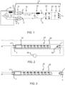
- Figure 1 shows a typical block diagram of a TLED that is compatible with an HF fluorescent ballast.
- the ballast 10 comprises a half-bridge parallel resonant converter and it drives an electronic (high frequency) ballast compatible TLED 12.
- the ballast 10 and high frequency compatible TLED 12 are connected via the connection pins 1 and 2 at one end of the TLED and via the connection pins 3 and 4 at the other end of the TLED (shown on one side of the circuit diagram for simplicity).
- a high frequency compatible TLED 12 typically comprises some or all of the building blocks depicted in Figure 1 . These are a filament emulation unit 14, a pin safety and start-up circuit 16, a matching circuit 18, a rectifier 20, an LED driver 22, a smoothing capacitor 23 and the LED string 24.
- the LED driver shown in Figure 1 is a shunt switch driver.
- ballast 10 The details of the design of the half-bridge ballast 10 are not shown in Figure 1 .
- This type of ballast is also just an example and other implementations such as push-pull converters are also possible and in use.
- this invention relates in particular to tubular LEDs designed for connection to an electromagnetic ballast, as well as direct mains. In both of these cases there is the problem of a high pin voltage, which does not arise with HF ballasts.
- the LED driver 32 comprises a rectifier, EMI filter, and a driver circuit (e.g., a switching mode power supply circuit, for example a Buck circuit).
- a driver circuit e.g., a switching mode power supply circuit, for example a Buck circuit.
- connection pins of the lamp (and the corresponding terminals of the end connectors of the luminaire housing) define a live terminal 1 at one end and a neutral terminal 3 at the other end.
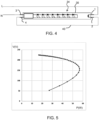
- EM ballast compatible tubes are typically designed for single-ended input as shown in Figure 2 , namely a driver being powered by the pins at one end only.
- a dummy starter 38 (which is typically a fused short) is used to close the current loop between the two ends.
- This connection scheme provides protection against pin leakage currents and thus provides pin safety because there is no conductive path from one end of the lamp itself to the other. Therefore, no leakage current can flow if somebody touches the pins at one end while the other end is already energized.
- the input power is applied to one end of the tube and the other end is provided with a fuse 36 for passing through the current to complete a circuit between external live L and neutral N connections.
- the glow starter in the fixture is then replaced with the dummy starter 38.
- the lamp can be installed with either orientation.
- the same TLED can often also be used for direct connection to the mains as shown in Figure 3 .
- the power is applied directly to the power-input side.
- the TLED in this case needs to be connected with the correct orientation.
- the design can be adapted to be suitable for orientation-independent connection direct to the mains by providing a jumper wire 40 as shown in Figure 4 .
- a problem is that the application of a mains voltage to the lamp holders may not be appropriate because the lamp holders are not designed to receive the mains voltage when they are instead connected through a ballast.
- the lamp holders for T8 and T5 lamps (which are G13 and G5 lamp holders) are manufactured to comply with the IEC 60400 standard - Lamp holders for tubular fluorescent lamps and starter holders. The standard allows for a minimum 2mm creepage between the two metal contacts of the socket of the lamp holder.
- TLEDs for mains and EM ballast applications are typically wired as a single-ended input as explained above, with the input voltage applied fully to one end of the tube (the other end being a dummy end), an issue arises because this is not an intended use of the lamp holder.
- the voltage between the two contacts of the lamp holder will be the mains voltage (or near the mains voltage when connected to an EM ballast).
- a minimum 2.5mm creepage is then required. Therefore, there is risk of tracking (i.e. insulator breakdown and over-heating risk) if the TLED lamp is used with a holder with only 2mm creepage distance.
- US2016/270162 A1 discloses an LED apparatus for replacing a fluorescent lamp.
- the lamp comprises a first driver for driving a first LED load and a second driver for driving a second LED load.
- the first driver, first LED load, second driver and second LED load can be coupled in series. This series connection is done inside the apparatus and not outside the apparatus. Therefore, when coupled in series, the first LED load and second LED load have an electrical connection.
- the LED apparatus is furthermore not suitable for direct connecting with a mains.
- the LED apparatus has current control if directly connected to mains. Therefore, the LEDs will be damaged when the apparatus is directly connected to mains.
- US 2016/113076 A1 discloses an LED lamp (referring to figure 10).
- the LED lamp comprises a first circuit powering first LEDs and a second circuit powering second LEDs.
- the first and second LEDs are electrically separated.
- the first circuit and the second circuit are electrically interconnected in series so that the mains voltage is shared between them. This connection is done inside the LED lamp.
- the interconnection is not done externally, wherein the external interconnection is provided by the fluorescent luminaire.
- US2012/147598 A1 discloses an LED based tube light.
- the tube light comprises a first LED group and a second LED group.
- the two groups are electrically isolated from one another.
- the first group is power via a power supply on one side of the tube lamp and the second group is powered via a second power supply on another side of the tube lamp.
- the first and second power supply are not externally coupled in series. Instead if both power supplies are fed by a single input voltage, the power supplies are coupled in parallel.
- a fluorescent luminaire comprising a tubular solid state lamp, comprising:
- This lamp design provides two drivers which may be connected (externally) in series so that the mains voltage is shared between them. In this way, each end connector of the lamp holder is only required to operate at half the mains voltage so that a lower, e.g. 2mm, creepage distance can be tolerated.
- the maximum allowed voltage between the contacts is 194V for a 2mm creepage distance (according to the IEC standard).
- the first and second drivers and their light source arrangement sections are completely isolated from each other internally within the lamp so that there is no electrical internal connection between the pins at one end and at the other. Thus, pin safety is ensured.
- the first and second drivers each comprise a switch mode power supply. They may for example comprise buck, boost or flyback converters. They are preferably operated with open loop control.
- the configuration of the invention, with two drivers in series sharing the mains input voltage, may be implemented with any known driver technology.
- the first and second drivers each comprise a linear driver, arranged to provide stable operation in series.
- the lamp further comprises an interconnection between one pin of the first pair of connection pins and one pin of the second pair of connection pins. This implements the series connection between the pairs of pins at each end, thereby placing the two drivers in series.
- the interconnection may comprise a dummy starter. This is suitable for connection to an electromagnetic fluorescent tube ballast.
- the interconnection may comprise a shorting wire. This is suitable for direct connection to the mains.
- the invention also provides a lighting installation, comprising:
- the lamp is in this way connected to existing electromagnetic ballast.
- Each end connector for example comprises a G13 or G5 lamp holder.
- Each end connector for example has a creepage distance of between 2mm and 2.5mm.
- the invention also provides a lighting installation, comprising:
- the lamp is in this way connected to the mains.
- the shorting wire forms the series connection between the drivers, externally of the lamp so that pin safety is maintained.
- the invention provides a tubular solid state lamp having a driver at each end each with an associated section of the solid state light source arrangement.
- the two drivers are for connection in series so that the mains voltage is shared between them.
- each end connector of the lamp holder is only required to operate at about half the mains voltage so that a lower creepage distance (e.g. 2mm) can be tolerated.
- a lower creepage distance e.g. 2mm
- These designs may be for an equal division of the mains voltage, but there may be slight deviation due to tolerances.
- the invention is directed to the problem of supplying a tubular solid state lamp with the mains through an existing tubular lamp fitting.
- Option 1 of a high power factor (PF) SMPS (Switch Mode Power Supply) driver is very popular in the market.
- PF power factor
- SMPS Switch Mode Power Supply
- the pin voltage ( ⁇ 225V) is not appropriate for tombstone connectors with a 2mm creepage distance.
- Option 2 is a shunt switch driver which periodically short-circuits the input in order to reduce the lamp power.
- the lamp power is regulated with the duty cycle of the shunt switch. This solution results in a high ballast loss and is not desired for this reason. Furthermore, this circuit is not suitable to work on direct mains.
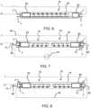
- Option 3 is to force the SMPS to reduce the input voltage.
- the relationship between lamp voltage and power is shown in Figure 5 , which shows the voltage V versus power P. If the input voltage is reduced to 194V, the lamp has to increase the input current significantly in order to create a larger drop over the electromagnetic ballast. The lamp power has to increase dramatically (even higher than the fluorescent lamps), which is not desired.
- Option 4 is to make a double-ended input with the two pins at each end shorted. One end is the live pin and the other end is the neutral pin. The pin voltage becomes zero. However, this requires a pin safety solution to limit the pin leakage.
- the pin safety solution can be mechanical, electro-mechanical or electrical, but is expensive.
- Figure 6 shows this option, in which there is a driver 60 at one end of the tubular lamp 30 and the required pin safety mechanism 62 at the other end.
- the invention is summarized by option 5, with two drivers in series.
- Figure 7 shows this solution. It comprises a tubular solid state lamp 70, comprising a first pair 72 of connection pins 1,2 at one end and a second pair 74 of connection pins 3,4 at the other end.
- the solid state light source arrangement comprises a first section 76 and a second section 78. These are independent sections with no electrical connections between them.
- a first driver 80 is electrically coupled to the first pair 72 of connection pins and is connected to the first section 76 of the solid state light source arrangement for driving the first section.
- a second driver 82 is electrically coupled to the second pair 74 of connection pins and connected to the second section 78 of the solid state light source arrangement for driving the second section.
- the two drivers are externally connected in series so that the mains voltage is shared between them.
- the split is preferably identical, so that the two drivers are identical and the LED string is split into two equal halves. As a result, each driver takes about half of the mains voltage (about 115V), which is safe to operate with a 2mm creepage lamp holder.
- the external connection is between one pin 2 of the first pair 72 of connection pins and one pin 4 of the second pair 74 of connection pins. This implements the series connection between the pairs of pins at each end, thereby placing the two drivers in series.
- the external interconnection can be provided by a fluorescent tube luminaire housing, a fluorescent luminaire. The interconnection can then be done via the existing wiring of the fluorescent luminaire. Upon correct insertion of the tubular solid state lamp, the series connection between the first driver 80 and the second driver 82 is made.
- the tubular lamp 70 connects to an existing fluorescent tube luminaire housing.
- This has end connectors 88 for example each of which comprises a G13 or G5 lamp holder.
- Each end connector for example has a creepage distance of between 2mm and 2.5mm.
- the interconnection comprises a dummy starter 84. This is for connection to an electromagnetic fluorescent tube ballast 86.
- One end connector 88 has a terminal for connection to a live terminal L and the other connector has a terminal for connection to a neutral terminal N.
- the other two end connector terminals are connected by the dummy starter.
- the interconnection comprises a shorting wire 90. This is for direct connection to the mains.
- the interconnection comprises a shorting wire 90. This is for direct connection to the mains.
- One end connector again has a terminal for connection to live terminal L and the other end connector has terminal for connection to a neutral terminal N.
- the other two terminals are connected by the shorting wire.
- the first and second drivers may each comprise a switch mode power supply. They may for example comprise buck, boost or flyback converters. They are preferably operated with open loop control.
- the configuration of the invention, with two drivers in series sharing the mains input voltage, may be implemented with any known driver technology.
- the first and second drivers may instead each comprise a linear driver, arranged to provide stable operation in series.
- Open loop control is desired because when the drivers are connected in series a closed loop control system may lead to unbalanced input between the two drivers.
- the invention provides a lighting tube which is EM ballast compatible but also suitable for direct mains driving.
- the solution addresses safety issues with existing 2mm creepage lamp holders.
Landscapes
- Engineering & Computer Science (AREA)
- General Engineering & Computer Science (AREA)
- Microelectronics & Electronic Packaging (AREA)
- Physics & Mathematics (AREA)
- Optics & Photonics (AREA)
- Power Engineering (AREA)
- Non-Portable Lighting Devices Or Systems Thereof (AREA)
- Circuit Arrangement For Electric Light Sources In General (AREA)
- Arrangement Of Elements, Cooling, Sealing, Or The Like Of Lighting Devices (AREA)
- Fastening Of Light Sources Or Lamp Holders (AREA)
Applications Claiming Priority (2)
| Application Number | Priority Date | Filing Date | Title |
|---|---|---|---|
| EP17195712 | 2017-10-10 | ||
| PCT/EP2018/077089 WO2019072698A1 (en) | 2017-10-10 | 2018-10-05 | TUBULAR SEMICONDUCTOR LIGHTING |
Publications (3)
| Publication Number | Publication Date |
|---|---|
| EP3695686A1 EP3695686A1 (en) | 2020-08-19 |
| EP3695686B1 true EP3695686B1 (en) | 2024-06-26 |
| EP3695686C0 EP3695686C0 (en) | 2024-06-26 |
Family
ID=60080632
Family Applications (1)
| Application Number | Title | Priority Date | Filing Date |
|---|---|---|---|
| EP18779399.7A Active EP3695686B1 (en) | 2017-10-10 | 2018-10-05 | Tubular solid state lighting |
Country Status (7)
| Country | Link |
|---|---|
| US (1) | US11079073B2 (pl) |
| EP (1) | EP3695686B1 (pl) |
| JP (1) | JP2020537300A (pl) |
| CN (1) | CN111201836B (pl) |
| ES (1) | ES2982332T3 (pl) |
| PL (1) | PL3695686T3 (pl) |
| WO (1) | WO2019072698A1 (pl) |
Families Citing this family (1)
| Publication number | Priority date | Publication date | Assignee | Title |
|---|---|---|---|---|
| CN116963354A (zh) * | 2022-04-18 | 2023-10-27 | 朗德万斯公司 | 用于驱动led管的led光引擎的驱动器 |
Family Cites Families (21)
| Publication number | Priority date | Publication date | Assignee | Title |
|---|---|---|---|---|
| JP4715547B2 (ja) * | 2006-02-23 | 2011-07-06 | パナソニック電工株式会社 | 照明用電源回路、照明装置、及び照明システム |
| KR100891740B1 (ko) * | 2007-11-13 | 2009-04-03 | 김철 | 형광등기구의 엘이디램프 연결장치 |
| JPWO2009145248A1 (ja) | 2008-05-29 | 2011-10-13 | ローム株式会社 | Ledランプ |
| FI20105359L (fi) | 2010-04-08 | 2011-10-09 | Valtavalo Oy | Led-valaisin ja led-valoputki |
| US8870415B2 (en) * | 2010-12-09 | 2014-10-28 | Ilumisys, Inc. | LED fluorescent tube replacement light with reduced shock hazard |
| TWM429810U (en) | 2011-11-28 | 2012-05-21 | Verticil Electronics Corp | Improved circuit board wiring structure of LED tube |
| DE102012000973A1 (de) | 2012-01-05 | 2013-07-11 | Trialed UK LTD | LED-Leuchtmittel |
| DE102012203886A1 (de) | 2012-03-13 | 2013-09-19 | Osram Gmbh | Leuchtdiodenlampe und Verfahren zum Fertigen einer Leuchtdiodenlampe |
| US8749167B2 (en) * | 2012-06-15 | 2014-06-10 | Lightel Technologies, Inc. | Linear solid-state lighting with voltage sensing mechanism free of fire and shock hazards |
| JP5140203B2 (ja) * | 2012-06-27 | 2013-02-06 | パナソニック株式会社 | Led点灯装置 |
| TWI518278B (zh) | 2012-10-11 | 2016-01-21 | 隆達電子股份有限公司 | 燈具 |
| JP6070049B2 (ja) * | 2012-10-18 | 2017-02-01 | 岩崎電気株式会社 | Led点灯装置及びled照明器具 |
| EP3017657A1 (en) * | 2013-07-05 | 2016-05-11 | Koninklijke Philips N.V. | Connection circuit for connecting a driver device to an external power supply for driving a load, in particular an led unit |
| ES2625004T3 (es) * | 2013-07-30 | 2017-07-18 | Philips Lighting Holding B.V. | Lámpara de repuesto LED para funcionamiento seguro con balasto electromagnético |
| TW201506301A (zh) | 2013-08-15 | 2015-02-16 | Luxul Technology Inc | Led燈管 |
| JP6277547B2 (ja) * | 2014-02-28 | 2018-02-14 | パナソニックIpマネジメント株式会社 | 光源装置および該光源装置を用いた照明器具 |
| DK3167225T3 (da) * | 2014-07-08 | 2018-01-29 | Philips Lighting Holding Bv | Led-rør |
| US20160113076A1 (en) * | 2014-10-20 | 2016-04-21 | Energy Focus, Inc. | Led lamp with dual mode operation |
| US9341359B1 (en) * | 2014-12-15 | 2016-05-17 | Jose M. Fernandez | Tubular light emitting diode lighting device having selectable light output |
| US9504122B2 (en) * | 2015-03-12 | 2016-11-22 | Microchip Technology Incorporated | Fluorescent replacement LED lamps |
| WO2017139914A1 (en) * | 2016-02-15 | 2017-08-24 | GE Lighting Solutions, LLC | Interface cap design for light tubes |
-
2018
- 2018-10-05 CN CN201880066005.0A patent/CN111201836B/zh active Active
- 2018-10-05 JP JP2020520217A patent/JP2020537300A/ja active Pending
- 2018-10-05 PL PL18779399.7T patent/PL3695686T3/pl unknown
- 2018-10-05 US US16/754,314 patent/US11079073B2/en active Active
- 2018-10-05 EP EP18779399.7A patent/EP3695686B1/en active Active
- 2018-10-05 WO PCT/EP2018/077089 patent/WO2019072698A1/en not_active Ceased
- 2018-10-05 ES ES18779399T patent/ES2982332T3/es active Active
Also Published As
| Publication number | Publication date |
|---|---|
| US20200309328A1 (en) | 2020-10-01 |
| EP3695686A1 (en) | 2020-08-19 |
| WO2019072698A1 (en) | 2019-04-18 |
| JP2020537300A (ja) | 2020-12-17 |
| PL3695686T3 (pl) | 2024-08-26 |
| US11079073B2 (en) | 2021-08-03 |
| EP3695686C0 (en) | 2024-06-26 |
| ES2982332T3 (es) | 2024-10-15 |
| CN111201836B (zh) | 2022-12-09 |
| CN111201836A (zh) | 2020-05-26 |
Similar Documents
| Publication | Publication Date | Title |
|---|---|---|
| US9338853B2 (en) | LED tube driver circuitry for ballast and non-ballast fluorescent tube replacement | |
| CA2861789C (en) | Led tube driver circuitry for ballast and non-ballast fluorescent tube replacement | |
| CN104871648B (zh) | 用于led串的应急照明转换 | |
| CN105359625B (zh) | 用于将驱动器设备连接到外部电源以便驱动负载尤其是led单元的连接电路 | |
| WO2011014111A1 (en) | Lighting system | |
| US20150260384A1 (en) | Fluorescent lamp fixture with leds | |
| EP3440894B1 (en) | Tubular device for fitting to a tubular light fitting | |
| EP3695686B1 (en) | Tubular solid state lighting | |
| CN207599381U (zh) | 可调光led灯管及led灯 | |
| CN107950077A (zh) | Led管灯 | |
| CN108886853A (zh) | 在荧光镇流器和led之间的转换电路 | |
| US12031689B2 (en) | Tubular device for fitting to a tubular light fitting | |
| EP3741188B1 (en) | Filament emulation circuit for a light emitting diode tube lamp | |
| CN102364218A (zh) | 一种可直接代替荧光灯使用的led日光灯 | |
| US7845972B1 (en) | Ceramic lampholder with a thermal switch in a radiator thermally bonded to its housing | |
| CN205546025U (zh) | 一种具有识别供电电源类型的led发光控制电路 | |
| CN111396839B (zh) | 接线端子和照明设备 | |
| CN100562199C (zh) | 独特的整流灯串 | |
| US10871280B2 (en) | Connection terminal and illumination device | |
| JP2020537300A5 (pl) | ||
| EP3086623B1 (en) | Device for the replacement of one or more pairs of linear fluorescent tubes installed in a luminaire and wired with magnetic conventional control gear and luminaire comprising the same | |
| CN118743313A (zh) | 用于tled灯的双抽头l2电源配置 | |
| CN102833925A (zh) | 旋入式单端电子镇流器 |
Legal Events
| Date | Code | Title | Description |
|---|---|---|---|
| STAA | Information on the status of an ep patent application or granted ep patent |
Free format text: STATUS: UNKNOWN |
|
| STAA | Information on the status of an ep patent application or granted ep patent |
Free format text: STATUS: THE INTERNATIONAL PUBLICATION HAS BEEN MADE |
|
| PUAI | Public reference made under article 153(3) epc to a published international application that has entered the european phase |
Free format text: ORIGINAL CODE: 0009012 |
|
| STAA | Information on the status of an ep patent application or granted ep patent |
Free format text: STATUS: REQUEST FOR EXAMINATION WAS MADE |
|
| 17P | Request for examination filed |
Effective date: 20200511 |
|
| AK | Designated contracting states |
Kind code of ref document: A1 Designated state(s): AL AT BE BG CH CY CZ DE DK EE ES FI FR GB GR HR HU IE IS IT LI LT LU LV MC MK MT NL NO PL PT RO RS SE SI SK SM TR |
|
| AX | Request for extension of the european patent |
Extension state: BA ME |
|
| DAV | Request for validation of the european patent (deleted) | ||
| DAX | Request for extension of the european patent (deleted) | ||
| STAA | Information on the status of an ep patent application or granted ep patent |
Free format text: STATUS: EXAMINATION IS IN PROGRESS |
|
| 17Q | First examination report despatched |
Effective date: 20210317 |
|
| REG | Reference to a national code |
Ref country code: DE Ref legal event code: R079 Free format text: PREVIOUS MAIN CLASS: H05B0033080000 Ipc: H05B0045357000 Ref country code: DE Ref legal event code: R079 Ref document number: 602018071034 Country of ref document: DE Free format text: PREVIOUS MAIN CLASS: H05B0033080000 Ipc: H05B0045357000 |
|
| GRAP | Despatch of communication of intention to grant a patent |
Free format text: ORIGINAL CODE: EPIDOSNIGR1 |
|
| STAA | Information on the status of an ep patent application or granted ep patent |
Free format text: STATUS: GRANT OF PATENT IS INTENDED |
|
| RIC1 | Information provided on ipc code assigned before grant |
Ipc: H05B 45/357 20200101AFI20220505BHEP |
|
| INTG | Intention to grant announced |
Effective date: 20220601 |
|
| GRAJ | Information related to disapproval of communication of intention to grant by the applicant or resumption of examination proceedings by the epo deleted |
Free format text: ORIGINAL CODE: EPIDOSDIGR1 |
|
| STAA | Information on the status of an ep patent application or granted ep patent |
Free format text: STATUS: EXAMINATION IS IN PROGRESS |
|
| INTC | Intention to grant announced (deleted) | ||
| P01 | Opt-out of the competence of the unified patent court (upc) registered |
Effective date: 20230530 |
|
| GRAP | Despatch of communication of intention to grant a patent |
Free format text: ORIGINAL CODE: EPIDOSNIGR1 |
|
| STAA | Information on the status of an ep patent application or granted ep patent |
Free format text: STATUS: GRANT OF PATENT IS INTENDED |
|
| INTG | Intention to grant announced |
Effective date: 20240131 |
|
| GRAS | Grant fee paid |
Free format text: ORIGINAL CODE: EPIDOSNIGR3 |
|
| GRAA | (expected) grant |
Free format text: ORIGINAL CODE: 0009210 |
|
| STAA | Information on the status of an ep patent application or granted ep patent |
Free format text: STATUS: THE PATENT HAS BEEN GRANTED |
|
| AK | Designated contracting states |
Kind code of ref document: B1 Designated state(s): AL AT BE BG CH CY CZ DE DK EE ES FI FR GB GR HR HU IE IS IT LI LT LU LV MC MK MT NL NO PL PT RO RS SE SI SK SM TR |
|
| REG | Reference to a national code |
Ref country code: GB Ref legal event code: FG4D |
|
| REG | Reference to a national code |
Ref country code: CH Ref legal event code: EP |
|
| REG | Reference to a national code |
Ref country code: DE Ref legal event code: R096 Ref document number: 602018071034 Country of ref document: DE |
|
| U01 | Request for unitary effect filed |
Effective date: 20240705 |
|
| U07 | Unitary effect registered |
Designated state(s): AT BE BG DE DK EE FI FR IT LT LU LV MT NL PT SE SI Effective date: 20240716 |
|
| P04 | Withdrawal of opt-out of the competence of the unified patent court (upc) registered |
Free format text: CASE NUMBER: APP_41240/2024 Effective date: 20240712 |
|
| PG25 | Lapsed in a contracting state [announced via postgrant information from national office to epo] |
Ref country code: HR Free format text: LAPSE BECAUSE OF FAILURE TO SUBMIT A TRANSLATION OF THE DESCRIPTION OR TO PAY THE FEE WITHIN THE PRESCRIBED TIME-LIMIT Effective date: 20240626 |
|
| PG25 | Lapsed in a contracting state [announced via postgrant information from national office to epo] |
Ref country code: GR Free format text: LAPSE BECAUSE OF FAILURE TO SUBMIT A TRANSLATION OF THE DESCRIPTION OR TO PAY THE FEE WITHIN THE PRESCRIBED TIME-LIMIT Effective date: 20240927 |
|
| REG | Reference to a national code |
Ref country code: ES Ref legal event code: FG2A Ref document number: 2982332 Country of ref document: ES Kind code of ref document: T3 Effective date: 20241015 |
|
| PG25 | Lapsed in a contracting state [announced via postgrant information from national office to epo] |
Ref country code: NO Free format text: LAPSE BECAUSE OF FAILURE TO SUBMIT A TRANSLATION OF THE DESCRIPTION OR TO PAY THE FEE WITHIN THE PRESCRIBED TIME-LIMIT Effective date: 20240926 Ref country code: HR Free format text: LAPSE BECAUSE OF FAILURE TO SUBMIT A TRANSLATION OF THE DESCRIPTION OR TO PAY THE FEE WITHIN THE PRESCRIBED TIME-LIMIT Effective date: 20240626 Ref country code: GR Free format text: LAPSE BECAUSE OF FAILURE TO SUBMIT A TRANSLATION OF THE DESCRIPTION OR TO PAY THE FEE WITHIN THE PRESCRIBED TIME-LIMIT Effective date: 20240927 Ref country code: RS Free format text: LAPSE BECAUSE OF FAILURE TO SUBMIT A TRANSLATION OF THE DESCRIPTION OR TO PAY THE FEE WITHIN THE PRESCRIBED TIME-LIMIT Effective date: 20240926 |
|
| U20 | Renewal fee for the european patent with unitary effect paid |
Year of fee payment: 7 Effective date: 20241025 |
|
| P05 | Withdrawal of opt-out of the competence of the unified patent court (upc) changed |
Free format text: CASE NUMBER: APP_41240/2024 Effective date: 20240716 |
|
| PGFP | Annual fee paid to national office [announced via postgrant information from national office to epo] |
Ref country code: GB Payment date: 20241022 Year of fee payment: 7 |
|
| PG25 | Lapsed in a contracting state [announced via postgrant information from national office to epo] |
Ref country code: IS Free format text: LAPSE BECAUSE OF FAILURE TO SUBMIT A TRANSLATION OF THE DESCRIPTION OR TO PAY THE FEE WITHIN THE PRESCRIBED TIME-LIMIT Effective date: 20241026 |
|
| PG25 | Lapsed in a contracting state [announced via postgrant information from national office to epo] |
Ref country code: CZ Free format text: LAPSE BECAUSE OF FAILURE TO SUBMIT A TRANSLATION OF THE DESCRIPTION OR TO PAY THE FEE WITHIN THE PRESCRIBED TIME-LIMIT Effective date: 20240626 |
|
| PG25 | Lapsed in a contracting state [announced via postgrant information from national office to epo] |
Ref country code: RO Free format text: LAPSE BECAUSE OF FAILURE TO SUBMIT A TRANSLATION OF THE DESCRIPTION OR TO PAY THE FEE WITHIN THE PRESCRIBED TIME-LIMIT Effective date: 20240626 Ref country code: SK Free format text: LAPSE BECAUSE OF FAILURE TO SUBMIT A TRANSLATION OF THE DESCRIPTION OR TO PAY THE FEE WITHIN THE PRESCRIBED TIME-LIMIT Effective date: 20240626 |
|
| PG25 | Lapsed in a contracting state [announced via postgrant information from national office to epo] |
Ref country code: SM Free format text: LAPSE BECAUSE OF FAILURE TO SUBMIT A TRANSLATION OF THE DESCRIPTION OR TO PAY THE FEE WITHIN THE PRESCRIBED TIME-LIMIT Effective date: 20240626 |
|
| PGFP | Annual fee paid to national office [announced via postgrant information from national office to epo] |
Ref country code: ES Payment date: 20241118 Year of fee payment: 7 |
|
| PG25 | Lapsed in a contracting state [announced via postgrant information from national office to epo] |
Ref country code: SM Free format text: LAPSE BECAUSE OF FAILURE TO SUBMIT A TRANSLATION OF THE DESCRIPTION OR TO PAY THE FEE WITHIN THE PRESCRIBED TIME-LIMIT Effective date: 20240626 Ref country code: SK Free format text: LAPSE BECAUSE OF FAILURE TO SUBMIT A TRANSLATION OF THE DESCRIPTION OR TO PAY THE FEE WITHIN THE PRESCRIBED TIME-LIMIT Effective date: 20240626 Ref country code: RO Free format text: LAPSE BECAUSE OF FAILURE TO SUBMIT A TRANSLATION OF THE DESCRIPTION OR TO PAY THE FEE WITHIN THE PRESCRIBED TIME-LIMIT Effective date: 20240626 Ref country code: IS Free format text: LAPSE BECAUSE OF FAILURE TO SUBMIT A TRANSLATION OF THE DESCRIPTION OR TO PAY THE FEE WITHIN THE PRESCRIBED TIME-LIMIT Effective date: 20241026 Ref country code: CZ Free format text: LAPSE BECAUSE OF FAILURE TO SUBMIT A TRANSLATION OF THE DESCRIPTION OR TO PAY THE FEE WITHIN THE PRESCRIBED TIME-LIMIT Effective date: 20240626 |
|
| PLBE | No opposition filed within time limit |
Free format text: ORIGINAL CODE: 0009261 |
|
| STAA | Information on the status of an ep patent application or granted ep patent |
Free format text: STATUS: NO OPPOSITION FILED WITHIN TIME LIMIT |
|
| REG | Reference to a national code |
Ref country code: CH Ref legal event code: PL |
|
| 26N | No opposition filed |
Effective date: 20250327 |
|
| PG25 | Lapsed in a contracting state [announced via postgrant information from national office to epo] |
Ref country code: MC Free format text: LAPSE BECAUSE OF FAILURE TO SUBMIT A TRANSLATION OF THE DESCRIPTION OR TO PAY THE FEE WITHIN THE PRESCRIBED TIME-LIMIT Effective date: 20240626 |
|
| PG25 | Lapsed in a contracting state [announced via postgrant information from national office to epo] |
Ref country code: CH Free format text: LAPSE BECAUSE OF NON-PAYMENT OF DUE FEES Effective date: 20241031 |
|
| PGFP | Annual fee paid to national office [announced via postgrant information from national office to epo] |
Ref country code: PL Payment date: 20250926 Year of fee payment: 8 |
|
| PG25 | Lapsed in a contracting state [announced via postgrant information from national office to epo] |
Ref country code: IE Free format text: LAPSE BECAUSE OF NON-PAYMENT OF DUE FEES Effective date: 20241005 |
|
| U20 | Renewal fee for the european patent with unitary effect paid |
Year of fee payment: 8 Effective date: 20251027 |