EP3695685B1 - Induktion heizung mit einer flexiblen heizhüllse, zur montage oder zerlegung von komponenten in einem turbinenmotor - Google Patents
Induktion heizung mit einer flexiblen heizhüllse, zur montage oder zerlegung von komponenten in einem turbinenmotor Download PDFInfo
- Publication number
- EP3695685B1 EP3695685B1 EP18793117.5A EP18793117A EP3695685B1 EP 3695685 B1 EP3695685 B1 EP 3695685B1 EP 18793117 A EP18793117 A EP 18793117A EP 3695685 B1 EP3695685 B1 EP 3695685B1
- Authority
- EP
- European Patent Office
- Prior art keywords
- component
- loops
- temperature
- cable
- hub
- Prior art date
- Legal status (The legal status is an assumption and is not a legal conclusion. Google has not performed a legal analysis and makes no representation as to the accuracy of the status listed.)
- Active
Links
Images


Classifications
-
- B—PERFORMING OPERATIONS; TRANSPORTING
- B23—MACHINE TOOLS; METAL-WORKING NOT OTHERWISE PROVIDED FOR
- B23P—METAL-WORKING NOT OTHERWISE PROVIDED FOR; COMBINED OPERATIONS; UNIVERSAL MACHINE TOOLS
- B23P6/00—Restoring or reconditioning objects
- B23P6/002—Repairing turbine components, e.g. moving or stationary blades, rotors
- B23P6/007—Repairing turbine components, e.g. moving or stationary blades, rotors using only additive methods, e.g. build-up welding
-
- G—PHYSICS
- G05—CONTROLLING; REGULATING
- G05D—SYSTEMS FOR CONTROLLING OR REGULATING NON-ELECTRIC VARIABLES
- G05D23/00—Control of temperature
- G05D23/19—Control of temperature characterised by the use of electric means
- G05D23/1927—Control of temperature characterised by the use of electric means using a plurality of sensors
-
- H—ELECTRICITY
- H01—ELECTRIC ELEMENTS
- H01F—MAGNETS; INDUCTANCES; TRANSFORMERS; SELECTION OF MATERIALS FOR THEIR MAGNETIC PROPERTIES
- H01F41/00—Apparatus or processes specially adapted for manufacturing or assembling magnets, inductances or transformers; Apparatus or processes specially adapted for manufacturing materials characterised by their magnetic properties
- H01F41/02—Apparatus or processes specially adapted for manufacturing or assembling magnets, inductances or transformers; Apparatus or processes specially adapted for manufacturing materials characterised by their magnetic properties for manufacturing cores, coils, or magnets
- H01F41/04—Apparatus or processes specially adapted for manufacturing or assembling magnets, inductances or transformers; Apparatus or processes specially adapted for manufacturing materials characterised by their magnetic properties for manufacturing cores, coils, or magnets for manufacturing coils
-
- H—ELECTRICITY
- H05—ELECTRIC TECHNIQUES NOT OTHERWISE PROVIDED FOR
- H05B—ELECTRIC HEATING; ELECTRIC LIGHT SOURCES NOT OTHERWISE PROVIDED FOR; CIRCUIT ARRANGEMENTS FOR ELECTRIC LIGHT SOURCES, IN GENERAL
- H05B6/00—Heating by electric, magnetic or electromagnetic fields
- H05B6/02—Induction heating
- H05B6/06—Control, e.g. of temperature, of power
-
- H—ELECTRICITY
- H05—ELECTRIC TECHNIQUES NOT OTHERWISE PROVIDED FOR
- H05B—ELECTRIC HEATING; ELECTRIC LIGHT SOURCES NOT OTHERWISE PROVIDED FOR; CIRCUIT ARRANGEMENTS FOR ELECTRIC LIGHT SOURCES, IN GENERAL
- H05B6/00—Heating by electric, magnetic or electromagnetic fields
- H05B6/02—Induction heating
- H05B6/10—Induction heating apparatus, other than furnaces, for specific applications
- H05B6/101—Induction heating apparatus, other than furnaces, for specific applications for local heating of metal pieces
-
- H—ELECTRICITY
- H05—ELECTRIC TECHNIQUES NOT OTHERWISE PROVIDED FOR
- H05B—ELECTRIC HEATING; ELECTRIC LIGHT SOURCES NOT OTHERWISE PROVIDED FOR; CIRCUIT ARRANGEMENTS FOR ELECTRIC LIGHT SOURCES, IN GENERAL
- H05B6/00—Heating by electric, magnetic or electromagnetic fields
- H05B6/02—Induction heating
- H05B6/36—Coil arrangements
- H05B6/40—Establishing desired heat distribution, e.g. to heat particular parts of workpieces
-
- H—ELECTRICITY
- H05—ELECTRIC TECHNIQUES NOT OTHERWISE PROVIDED FOR
- H05B—ELECTRIC HEATING; ELECTRIC LIGHT SOURCES NOT OTHERWISE PROVIDED FOR; CIRCUIT ARRANGEMENTS FOR ELECTRIC LIGHT SOURCES, IN GENERAL
- H05B6/00—Heating by electric, magnetic or electromagnetic fields
- H05B6/02—Induction heating
- H05B6/36—Coil arrangements
- H05B6/44—Coil arrangements having more than one coil or coil segment
-
- F—MECHANICAL ENGINEERING; LIGHTING; HEATING; WEAPONS; BLASTING
- F01—MACHINES OR ENGINES IN GENERAL; ENGINE PLANTS IN GENERAL; STEAM ENGINES
- F01D—NON-POSITIVE DISPLACEMENT MACHINES OR ENGINES, e.g. STEAM TURBINES
- F01D5/00—Blades; Blade-carrying members; Heating, heat-insulating, cooling or antivibration means on the blades or the members
- F01D5/02—Blade-carrying members, e.g. rotors
- F01D5/06—Rotors for more than one axial stage, e.g. of drum or multiple disc type; Details thereof, e.g. shafts, shaft connections
- F01D5/063—Welded rotors
-
- F—MECHANICAL ENGINEERING; LIGHTING; HEATING; WEAPONS; BLASTING
- F05—INDEXING SCHEMES RELATING TO ENGINES OR PUMPS IN VARIOUS SUBCLASSES OF CLASSES F01-F04
- F05D—INDEXING SCHEME FOR ASPECTS RELATING TO NON-POSITIVE-DISPLACEMENT MACHINES OR ENGINES, GAS-TURBINES OR JET-PROPULSION PLANTS
- F05D2230/00—Manufacture
- F05D2230/20—Manufacture essentially without removing material
- F05D2230/23—Manufacture essentially without removing material by permanently joining parts together
- F05D2230/232—Manufacture essentially without removing material by permanently joining parts together by welding
-
- F—MECHANICAL ENGINEERING; LIGHTING; HEATING; WEAPONS; BLASTING
- F05—INDEXING SCHEMES RELATING TO ENGINES OR PUMPS IN VARIOUS SUBCLASSES OF CLASSES F01-F04
- F05D—INDEXING SCHEME FOR ASPECTS RELATING TO NON-POSITIVE-DISPLACEMENT MACHINES OR ENGINES, GAS-TURBINES OR JET-PROPULSION PLANTS
- F05D2230/00—Manufacture
- F05D2230/60—Assembly methods
-
- F—MECHANICAL ENGINEERING; LIGHTING; HEATING; WEAPONS; BLASTING
- F05—INDEXING SCHEMES RELATING TO ENGINES OR PUMPS IN VARIOUS SUBCLASSES OF CLASSES F01-F04
- F05D—INDEXING SCHEME FOR ASPECTS RELATING TO NON-POSITIVE-DISPLACEMENT MACHINES OR ENGINES, GAS-TURBINES OR JET-PROPULSION PLANTS
- F05D2230/00—Manufacture
- F05D2230/70—Disassembly methods
-
- H—ELECTRICITY
- H05—ELECTRIC TECHNIQUES NOT OTHERWISE PROVIDED FOR
- H05B—ELECTRIC HEATING; ELECTRIC LIGHT SOURCES NOT OTHERWISE PROVIDED FOR; CIRCUIT ARRANGEMENTS FOR ELECTRIC LIGHT SOURCES, IN GENERAL
- H05B2206/00—Aspects relating to heating by electric, magnetic, or electromagnetic fields covered by group H05B6/00
- H05B2206/02—Induction heating
- H05B2206/022—Special supports for the induction coils
Definitions
- Disclosed embodiments relate to assembly and disassembly of components of turbine engines. More particularly, some disclosed embodiments relate to assembly and disassembly of hubs, including power take-off hubs, and mating shafts of turbine engines.
- Gas turbine engines typically comprise a casing or cylinder for housing a compressor section, a combustion section, and a turbine section.
- a supply of air is compressed in the compressor section and is directed into the combustion section.
- the compressed air enters the combustion inlet and mixes with fuel.
- the air/fuel mixture is then combusted to produce high temperature and high-pressure (working) gas. This working gas then travels through the transition and into the turbine section of the turbine.
- the turbine section typically comprises rows of vanes, which direct the working gas to the airfoil portions of the turbine blades.
- the working gas travels through the turbine section, causing the turbine blades to rotate, thereby turning a rotor attached thereto.
- the rotor is also attached to the compressor section, thereby turning the compressor and may be operatively connected to an electrical generator for producing electricity.
- High efficiency of a combustion turbine is improved by heating the gas flowing through the combustion section to as high a temperature as is practical.
- the induction heating apparatus comprises a frame for applying around the pipe joint, and an induction heating coil made from Litz cable wires.
- Document WO 2007/128384 A2 describes a device and a method to establish a Joint connection with a sleeve comprising at least one susceptor by inductive heating by a welding device.
- Document GB 2 104 359 A discloses an induction heating ring, which is adapted for removably surrounding a pipe and is provided with two frames, connected in end to end circumferential relationship. A plurality of electrically conducting wires are carried upon the frames.
- An electrical coupling assembly comprises a male connector to be in received in a female connector, wherein each connector being provided with a plurality of coil contacts, each connected to an end of the conducting wires.
- Document WO 2015/154833 A1 describes a method for dismounting an annular sleeve that is shrunk on a roll core of a press roll, wherein the annular sleeve is heated so as to expand and is removed from the roll core. Said method is characterized in that the annular sleeve is inductively heated using an induction coil.
- Document WO 2017/150627 A1 discloses a heat processing device with a heating unit and a workpiece, which is inductively heated to a target temperature.
- the heating unit comprises a plurality of coil members, each having a ring-shaped coil portion capable of surrounding the workpiece and disposed coaxially to the workpiece, and a frame body supporting each of the coil members to be movable in the axial direction while maintaining the coil portions coaxial to each other.
- aspects of the present disclosure relate to assembly and/or disassembly of components within a gas turbine engine, such as hubs and mating shafts.
- Mating hub and shaft, as well as other similarly mating components are assembled or disassembled by wrapping a flexible heating jacket around the hub. Ends of cable loops in the heating jacket are joined by selectively separable electrical connectors. The separated ends of the cable loops are wrapped around the hub and re-joined by coupling the respective electrical connectors.
- the hub is heated by supplying electric current through the cable loops of the jacket with a power source, increasing relative differential temperature of the hub higher than that of the shaft. The heated hub expands; this facilitates assembly or disassembly of the mating hub and shaft.
- local heating of the mating hub and shaft is selectively modified by altering pitch spacing between individual coil loops, or by altering power applied to individual coil loops.
- a controller regulates power applied to the coil loops by the power source.
- the controller regulates power applied to the coil loops based at least in part by temperature of the mating components.
- the controller determines temperature of the mating components with hub and/or shaft sensors coupled to it.
- Exemplary embodiments described herein feature an induction heating apparatus for disassembly or assembly of a first component, such as a hub, from a second component, such as a shaft, of a gas turbine engine.
- the exemplary apparatus includes a flexible heating jacket for wrapping about an outer circumferential surface of the first component.
- the heating jacket includes an electrically conductive, flexible cable, having a plurality of loops.
- the loops collectively define a three-dimensional profile, with relative pitch orientation defined between adjacent loops.
- the three-dimensional profile is selectively sized to abut against and envelop the first component when wrapped by the jacket.
- a pair of first and second coil holders are respectively coupled to each respective loop of the cable, for maintaining the respective relative pitch orientation between adjacent loops of the plurality loops.
- a plurality of electrically conductive electrical connectors is interposed between the first and second coil holders. Each electrical connector has selectively separable first and second connector portions, respectively conductively coupled in series within a corresponding loop of the cable.
- the apparatus includes a power source coupled to the cable of the heating jacket, for heating the cable loops when the first and second connector portions of the plurality of electrical connectors are respectively coupled to each other. The power source passes current through the respective loops, so that the first component is heated to a higher temperature than the second component.
- a flexible heating jacket (40, 70, 80, 90) is provided.
- the jacket includes an electrically conductive, flexible cable, having a plurality of loops.
- a plurality of electrically conductive electrical connectors respectively having selectively separable first and second connector portions, are conductively coupled in series within a corresponding loop of the cable.
- Each of the respective first and second connector portions of each electrical connector are separated from each other.
- An outer surface of the first component is inserted within the jacket, by passing the first component between separated first and second connector portions of each electrical connector.
- each electrical connector is coupled to each other; this envelops the outer circumferential surface of the first component in abutting contact with the loops.
- the first component is heated by supplying electrical current to the flexible cable of the heating jacket with a power source, increasing relative temperature of the first component higher than that of the second component, and expanding an inner surface of the first component greater than an outer surface of the second component. Then, the heated inner surface of the first component and the mating outer surface of the second component are separated or joined.
- the current procedures employ a thermal blanket and liquid nitrogen to overcome the interference designed in the component.
- Fig. 1 illustrates a schematic view of a gas turbine component 5 that comprises a hub 10 (e.g., a PTO hub) and shaft 12.
- the hub 10 is secured on a shaft 12 via an interference fit.
- a temperature differential is created between the hub 10 and the shaft 12.
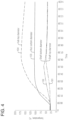
- a temperature difference of 70 °C between PTO hub 10 and shaft 12 may be needed to achieve the desired interference expansion between the hub 10 and shaft 12 so as to remove the shaft 12 from the hub 10.
- a temperature difference of 70 °C takes into consideration the average temperature at the mid-section of the top flange 13 of hub 10.
- the top flange 13 of the hub 10 has a significant mass; its expansion is also needed to allow the inner smaller diameter of the hub 10 to open.
- a lack of uniformity in the temperature of the hub 10 can cause internal stresses in the portion of the hub 10 that resists the expansion of the inner interference diameter.
- a temperature difference of 70° C is proposed, that a smaller or greater temperature difference may also be sufficient or exceed the needed temperature difference for extraction.
- a temperature difference within the range of 55-85 °C is preferred for the removal of the shaft 12 from the hub 10.
- a favourable delta T of 75 °C can be achieved at the interface of the hub 10 and the shaft 12 within two minutes of the application of induction heating.
- the interface surfaces are defined by an inner circumferential surface of the hub 10 and the outer circumferential surface of the shaft 12.
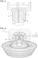
- Applied induction heat is radiating from the hub outer surface 18 inwards towards the hub inner surface 17 when using the induction apparatus 25 (discussed in detail below with respect to Fig. 4 ).
- the average temperature of the hub 10 is in fact higher than that which is measured by the hub thermocouples 15 and the shaft thermocouples 16. This means the expansion of the hub 10 is greater than that which would be interpreted from simply considering the readings from the hub thermocouples 15 and the shaft thermocouples 16.
- thermocouples 15 and the shaft thermocouples 16 are shown located at the hub inner surface 17 and the shaft outer surface 19 they may be located at other locations on the hub 10 and the shaft 12. However, the locations illustrated are preferred due to potential interferences that may occur due to process of induction. When located at other locations, their locations may be taken into account in order to control effectively the application of induction heating. Furthermore, while the instant invention is shown having eight thermocouples there may be more or fewer depending on the needs and subsequent accuracy desired. Additionally, while thermocouples are shown, there does not need to be thermocouples. The thermocouples enable measurement of the heat to control more accurately the application of induction heating.
- the cable 26 is preferably a dry insulated cable.
- the insulation for the cable is preferably a fabric/glass.
- the cable 26 is preferably wound around the frame 24 ten times. The cable 26 is wound in this fashion in order to provide induction heating to the hub 10. However, it should be understood that it may be wound around more or less depending on the desired induction heat-transfer rate and local application to the hub 10 or other engine component structure.
- the proposed induction process provides rapid and uniform heating to the gas turbine component 5.
- the process provides the best conditions for extracting a shaft 12 from the hub 10, in this instance a M08 hub.
- Benefits associated with the process are that no liquid nitrogen is required, which saves additional costs.
- Another benefit is saving time by not needing to perform the intricate heating and cooling process.
- Still another benefit is saving time by not needing to perform unnecessary repairs, as there will be no damage on the PTO hub 10 and shaft 12. Therefore, there is no scrap or repair needed and no replicas/lab analysis required.
- Induction heating devices utilizing the induction process described herein are not limited to the applications discussed so far herein. Removal/disassembly and/or placement/assembly of additional mating components in the gas turbine engine may be accomplished in the same manner.
- other induction heating apparatus and method embodiments utilize flexible, induction heating jackets where power is applied by a power supply to the cable loops therein.
- a controller regulates the power applied to the flexible, induction heating jacket.
- the three-dimensional profile of the helically-wrapped cable 42 and its cable loops 44 are selectively sized to abut against and envelop the outer circumferential surface 18 of the hub 10 as it is wrapped by the jacket, similar to that shown in the fixed apparatus 25 of Fig. 5 .
- the flexible nature of the jacket 40 allows it to be wrapped about the hub 10 and shaft 16 interface while those components remain in situ within a partially assembled or disassembled engine.
- the heating jacket 40 has a pair of first 46 and second 48 coil holders, and optional additional coil holders 50 that are respectively coupled to each respective loop 44 of the cable 42, for maintaining the respective relative pitch orientation P between adjacent loops of the plurality loops.
- the number and orientation of coil holders varies in different embodiments.
- the coil holders incorporate handles 52, for manoeuvring the jacket 40 about a hub or other component.
- each of the respective first connector 56 portions is coupled to the first coil holder 46, electrically isolated from all of the other electrical connectors 54.
- Each of the respective second connector 58 portions is coupled to the second coil holder 48, also electrically isolated from all of the other electrical connectors 54.
- the first f56 and second 58 mating connector portions are retained in aligned, coupled position by the first 46 and second 48 coil holders. Those coil holders 46, 48 in turn are retained in alignment by a plurality of alignment pins 60 and fasteners 62.
- a power source 64 is coupled in series to the helically wrapped cable 42 of the heating jacket 40, for heating the cable loops 44 when the first 56 and second 58 connector portions of the plurality of electrical connectors 54 are respectively coupled to each other, as shown in FIGs. 7-10 .
- the power source 64 of the embodiment of Figs. 7-10 passes current through the respective loops 44, so that the hub 10 is heated to a higher temperature than the shaft 12.
- the power source 64 applies power to the cable 42 at one or more predetermined rates and time durations under supervision of a controller 30, as was previously described with respect to the apparatus 25 and controller 30 of Fig. 6 .
- the controller 30 is coupled to the arrays of the hub temperature sensors 15 and the shaft temperature sensors 16, in the same way or in a similar way as the corresponding sensor arrays of Figs. 2 and 3 .
- the connection dots (lettered lowercase a, b, c...) of the sensors 15, 16 are in communication with the controller's sensor inputs connection dot (labelled a...x).
- the controller 30 is coupled to all of the temperature sensors 15, 16 in feedback loops, for regulating current flow passed through the cable loops 44 by the power source 64, so that temperature sensed by all of the temperature sensors remains below a predetermined maximum temperature.
- the controller 30 regulates current power intensity flow time duration in accordance with a predetermined regulation plan, but it alters the regulation plan if temperature sensed by the at least one temperature sensor 15 or 16 exceeds one or more predetermined temperatures. In some embodiments, separating or joining the heated hub 10 and shaft 12 interface is performed when respective temperatures measured by all of the first sensors 15 exceeds respective temperatures measured by all of the second sensors 16 by a predetermined temperature difference (e.g., 55-85°C).
- a predetermined temperature difference e.g., 55-85°C
- the controller 30 incorporates a processor 32 that accesses and executes instructions stored in non-volatile memory 34.
- the instructions stored in the memory 34 and executed by the processor 32 enables the controller 30 to perform the temperature monitoring and power source 64 control functions.
- exemplary embodiments of the disclosure may be implemented in various forms of hardware, software, firmware, special purpose processors, or a combination thereof.
- aspects of the invention embodiments are implemented in software as a program tangibly embodied on a program storage device. The program may be uploaded to, and executed by, a machine comprising any suitable architecture.
- the machine is implemented on a computer platform having hardware such as one or more central processing units (CPU), a random access memory (RAM), and input/output (I/O) interface(s).
- the computer platform also includes an operating system and microinstruction code.
- the various processes and functions described herein may be either part of the microinstruction code or part of the program (or combination thereof) which is executed via the operating system.
- various other peripheral devices may be connected to the computer/controller platform.
- the heating circuit within the flexible heating jacket 40 of Fig. 10 incorporates a single helical cable 42 with multiple loops 44. Localized variation in induction heating to the hub 10 is accomplished by selectively varying pitch P of the cable loops 44.
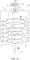
- the flexible heating jacket embodiments of Figs. 11-13 respectively have heating jackets with heating circuits comprising arrays of discrete closed loops. Localized variation in induction heating to the hub 10 and the shaft 12 to one or more desired differential temperatures is accomplished by selectively varying power applied to each individual loop.
- each loop 72 is coupled independently to a power source 64.
- each loop 82 is coupled in parallel to a power source 64.
- the flexible heating jacket 70 incorporates a cable bundle 71 comprising a plurality of electrically isolated cable loops 72.
- Each loop 72 incorporates an electrical connector 74, with first 76 and second 78 connector portions.
- Each of the loops 72 within the cable bundle 71 is separately coupled to its power source 64.
- the power source 64 comprises a multi-channel power source or separate dedicated power sources, for providing power, regulated by the controller 64 to each of the loops 72.
- Localized heating about the hub 10 and shaft 12 is varied by varying power supplied to each individual loop 72 and by selectively varying pitch P between loops.
- the flexible heating jacket 80 incorporates a cable bundle 81 comprising a plurality of electrically isolated cable loops 82.
- Each loop 82 incorporates an electrical connector 84, with first 84A and second 84B connector portions.
- Each of the loops 82 within the cable bundle 81 is coupled to its power source 64 in parallel with the other loops via the power cables 86 and 88.
- Localized heating about the hub 10 and shaft 12 is varied by varying power supplied to each individual loop 82 and by selectively varying pitch P between loops.
- power supplied to any individual loop is selectively varied by altering its resistivity (R1-R6).
- the flexible heating jacket 90 incorporates a cable bundle 91 comprising a plurality of serially coupled cable loops 92.
- Each loop 92 incorporates an electrical connector 94, with first 96 and second 98 connector portions.
- Each of the loops 92 within the cable bundle 91 is coupled to its power source 64 in series with the other loops.
- Localized heating about the hub 10 and shaft 12 is varied by varying the cascading power drop to each downstream individual loop 92 and by selectively varying pitch P between loops.
- power supplied to any individual loop is selectively varied by altering its resistivity (R7, R8, and R9). Cascading drop in power supplied to each downstream loop 92 results in higher heat induction applied at the upper end of the hub 10, in the localized zone where there is a thicker hub collar, and relatively lower heat induction applied at the lower, thinner end of the hub.
Landscapes
- Physics & Mathematics (AREA)
- Electromagnetism (AREA)
- Engineering & Computer Science (AREA)
- Power Engineering (AREA)
- Manufacturing & Machinery (AREA)
- General Physics & Mathematics (AREA)
- Automation & Control Theory (AREA)
- Mechanical Engineering (AREA)
- General Induction Heating (AREA)
Claims (12)
- Induktionsheizeinrichtung zur Demontage oder Montage einer ersten Komponente von einer zweiten Komponente eines Gasturbinentriebwerks, umfassend
einen flexiblen Heizmantel (70, 80, 90) zum Wickeln um eine äußere Umfangsfläche (18) einer ersten Komponente (10) eines Gasturbinentriebwerks (2), wobei der Heizmantel (70, 80, 90) Folgendes aufweist:ein elektrisch leitfähiges, flexibles Kabel (71, 81, 91), das mehrere Schleifen (72, 82, 92) aufweist, wobei die Schleifen (72, 82, 92) gemeinsam ein dreidimensionales Profil definieren, das eine relative Teilungsausrichtung (P) zwischen benachbarten Schleifen (72, 82, 92) definiert, wobei das dreidimensionale Profil selektiv so dimensioniert ist, dass es an der ersten Komponente (10) anliegt und diese einhüllt, wenn sie von dem Mantel (70, 80, 90) umwickelt ist;ein Paar erster (46) und zweiter (48) Spulenhalter, die jeweils mit jeder jeweiligen Schleife (72, 82, 92) des Kabels (71, 81, 91) gekoppelt sind, um die jeweilige relative Teilungsausrichtung (P) zwischen benachbarten Schleifen der mehreren Schleifen (72, 82, 92) aufrechtzuerhalten; undmehrere elektrisch leitfähige elektrische Verbinder (74, 84, 94), die zwischen den ersten (46) und zweiten (48) Spulenhaltern angeordnet sind, wobei jeder elektrische Verbinder (74, 84, 94) in einer entsprechenden Schleife (72, 82, 92) des Kabels (71, 81, 91) trennbare erste (76, 84A, 96) und zweite (78, 84B, 98) Verbinderabschnitte aufweist, die jeweils leitfähig in Reihe innerhalb der entsprechenden Schleife (72, 82, 92) des Kabels (71, 81, 91) gekoppelt sind; undeine Leistungsquelle (64), die mit dem Kabel (71, 81, 91) des Heizmantels (70, 80, 90) gekoppelt ist, um die erste Komponente (10) zu erwärmen, wenn die ersten (76, 84A, 96) und zweiten (78, 84B, 98) Verbinderabschnitte der mehreren elektrischen Verbinder (74, 84, 94) jeweils miteinander gekoppelt sind, wobei die Erwärmung durch Leiten von Strom durch die jeweiligen Kabelschleifen (72, 82, 92) erreicht wird, so dass die erste Komponente (10) auf eine höhere Temperatur erwärmt wird als die zweite Komponente (12),dadurch gekennzeichnet, dass die mehreren Schleifen (72, 82, 92) als diskrete geschlossene Schleifen (72, 82, 92) ausgebildet sind,wobei zum lokalisierten Erwärmen um die erste Komponente (10) und die zweite Komponente (12) die Induktionsheizeinrichtung dazu ausgestaltet ist, den Teilungsabstand (P) zwischen den benachbarten Schleifen (72, 82, 92) selektiv zu variieren, um die lokale Wärmeübertragungsrate auf die erste Komponente (10) selektiv zu variieren, und wobei die Leistungsquelle (64) dazu ausgeführt ist, die an jede einzelne Schleife (72, 82, 92) angelegte Leistung zu variieren. - Induktionsheizeinrichtung nach Anspruch 1, wobei das Kabel (71, 81, 91) ferner ein Array aus den mehreren diskreten geschlossenen Schleifen (72, 82, 92) umfasst, die jeweils unabhängig (72) oder in Reihe (91) oder in parallelen (86, 88) Schaltungen elektrisch mit ihrer entsprechenden Leistungsquelle (64) gekoppelt sind.
- Induktionsheizeinrichtung nach den Ansprüchen 1-2, ferner umfassend:einen der ersten (76, 84A, 96) oder der zweiten (78, 84B, 98) Verbinderabschnitte mindestens eines elektrischen Verbinders (74, 84, 94), der mit dem ersten Spulenhalter (46) gekoppelt ist, der elektrisch von allen anderen elektrischen Verbindern (54) isoliert ist, während er elektrisch leitfähig in Reihe mit seiner entsprechenden Kabelschleife (72, 82, 92) gekoppelt ist; den anderen der ersten (76, 84A, 96) oder der zweiten (78, 84B, 98) Verbinderabschnitte des mindestens einen elektrischen Verbinders (74, 84, 94), der mit dem zweiten Spulenhalter (48) gekoppelt ist, der elektrisch von allen anderen elektrischen Verbindern (74, 84, 94) isoliert ist, während er elektrisch leitfähig in Reihe mit seiner entsprechenden Kabelschleife (72, 82, 92) gekoppelt ist,mindestens einen der ersten (76, 84A, 96) und der zweiten (78, 84B, 98) Verbinderabschnitte, jeweils umfassend einführbare männliche und weibliche Gegenabschnitte, die selektiv in einer eingeführten Position gehalten werden, wenn die ersten (46) und zweiten (48) Spulenhalter miteinander gekoppelt sind.
- Induktionsheizeinrichtung nach den Ansprüchen 1-3, ferner umfassend:mindestens einen Temperatursensor (15), der mit der ersten Komponente (10) gekoppelt ist, um eine Temperatur der ersten Komponente zu erfassen;eine Steuerung (30), die mit dem mindestens einen Temperatursensor (15) und der Leistungsquelle (64) gekoppelt ist, um einen durch die Leistungsquelle (64) durch die Schleifen (72, 82, 92) geleiteten Stromfluss zumindest teilweise basierend auf der durch den Temperatursensor (15) erfassten Temperatur der ersten Komponente (10) zu regeln,wobei die Steuerung (30) eine Stromleistungsintensität und eine Anlagezeit gemäß einem vorbestimmten Regelplan regelt, jedoch den Regelplan ändert, wenn die durch den mindestens einen Temperatursensor (15) erfasste Temperatur eine oder mehrere vorbestimmte Temperaturen überschreitet.
- Induktionsheizeinrichtung nach Anspruch 1, wobei die ersten und zweiten Komponenten jeweils eine Nabe (10) und eine Welle (12) umfassen.
- Verfahren zur Demontage oder Montage einer Innenfläche einer ersten Komponente von einer Gegenaußenfläche einer zweiten Komponente eines Gasturbinentriebwerks, umfassend:Bereitstellen eines flexiblen Heizmantels (70, 80, 90), der Folgendes aufweist: ein elektrisch leitfähiges, flexibles Kabel (71, 81, 91), wobei das Kabel mehrere Schleifen (72, 82, 92) und mehrere elektrisch leitfähige elektrische Verbinder (74, 84, 94) aufweist, die jeweils trennbare erste (76, 84A, 96) und zweite (78, 84B, 98) Verbinderabschnitte aufweisen, die jeweils leitfähig in Reihe innerhalb einer entsprechenden Schleife (72, 82, 92) des Kabels (71, 81, 91) gekoppelt sind;Trennen jedes der jeweiligen ersten (76, 84A, 96) und zweiten (78, 84B, 98) Verbinderabschnitte jedes elektrischen Verbinders (74, 84, 94) voneinander;Einführen einer Außenfläche (18) der ersten Komponente (10) in den Mantel (70, 80, 90) durch Hindurchführen der ersten Komponente (10) zwischen getrennten ersten (76, 84A, 96) und zweiten (78, 84B, 98) Verbinderabschnitten jedes elektrischen Verbinders (74, 84, 94),Koppeln der jeweiligen ersten (76, 84A, 96) und zweiten (78, 84B, 98) Verbinderabschnitte jedes elektrischen Verbinders (74, 84, 94) miteinander, wobei die Außenumfangsfläche der ersten Komponente (10) in anliegendem Kontakt mit den Schleifen (72, 82, 92) eingehüllt wird;Erwärmen der ersten Komponente (10) durch Zuführen von elektrischem Strom zu dem flexiblen Kabel (71, 81, 91) des Heizmantels (70, 80, 90) mit einer Stromquelle (64), wobei die relative Temperatur der ersten Komponente (10) stärker als die einer zweiten Komponente (12) erhöht wird und eine Innenfläche (17) der ersten Komponente (10) stärker als eine Außenfläche (19) der zweiten Komponente (12) ausgedehnt wird; undTrennen oder Verbinden der erwärmten Innenfläche (17) der ersten Komponente (10) und der Gegenaußenfläche (19) der zweiten Komponente (10),dadurch gekennzeichnet, dass die mehreren Schleifen (72, 82, 92) als diskrete geschlossene Schleifen (72, 82, 92) ausgebildet sind, wobei das Verfahren ferner selektives Variieren einer Wärmeinduktionsrate um die erste Komponente (10) durch selektives Variieren einer Ausrichtung des relativen Teilungsabstands (P) zwischen benachbarten Schleifen (72, 82, 92) in dem flexiblen Heizmantel (70, 80, 90) umfasst, wobei das lokalisierte Erwärmen um die erste Komponente (10) und die zweite Komponente (12) durch selektives Variieren des Teilungsabstands (P) zwischen den Schleifen (72, 82, 92) und durch Variieren der an jede einzelne Schleife (72, 82, 92) angelegten Leistung variiert wird.
- Verfahren nach Anspruch 6, ferner umfassend Reduzieren einer Ausrichtung des relativen Teilungsabstands (P) zwischen benachbarten Schleifen (72, 82, 92) in Bereichen der ersten Komponente (10) mit größerer thermischer Masse zwischen (13) den jeweiligen Außenflächen der ersten (10) und zweiten Komponente (12) und Erhöhen des relativen Teilungsabstands zwischen benachbarten Schleifen in Bereichen der ersten (10) Komponente mit geringerer thermischer Masse (13A) dazwischen.
- Verfahren nach den Ansprüchen 6-7, ferner umfassend Regeln des Stromflusses, der durch die Stromquelle (64) durch die Schleifen (72, 82, 92) geleitet wird, mit einer Steuerung (30), die mit der Leistungsquelle gekoppelt ist, wobei die Steuerung (30) eine Stromleistungsintensität und eine Anlagezeit gemäß einem vorbestimmten Regelplan regelt, wobei der Regelplan eine lokale Temperatur um die gesamte erste Komponente (10) unterhalb einer vorbestimmten maximalen Temperatur hält.
- Verfahren nach Anspruch 8, ferner umfassend:Erfassen einer Temperatur der ersten Komponente (10) an einer oder mehreren Stellen davon mit jeweiligen Temperatursensoren (15), die mit der Steuerung (30) in einer Rückkopplungsschleife gekoppelt sind; undRegeln eines Stromflusses, der durch die Stromquelle (64) durch die Schleifen (72, 82, 92)geleitet wird, mit der Steuerung zumindest teilweise basierend auf der durch einen oder mehrere der Temperatursensoren erfassten Temperatur der ersten Komponente.
- Verfahren nach Anspruch 9, ferner umfassend:Erfassen einer Temperatur der ersten Komponente (10) mit mehreren Temperatursensoren (15), die mit der ersten Komponente in einem Array gekoppelt sind;Regeln einer Stromleistungsintensität und einer Anlagezeit mit der Steuerung (30) gemäß einem vorbestimmten Regelplan, jedoch Ändern des Regelplans, wenn die durch einen beliebigen Temperatursensor (15) erfasste Temperatur eine oder mehrere vorbestimmte Temperaturen überschreitet.
- Verfahren nach den Ansprüchen 9-10, ferner umfassend:Erfassen einer Temperatur der ersten Komponente (10) mit mehreren ersten Temperatursensoren (15), die mit der ersten Komponente in einem Array gekoppelt sind;Erfassen einer Temperatur der zweiten Komponente (12) mit mehreren zweiten Temperatursensoren (16), die in einem Array damit gekoppelt sind;Regeln einer Stromleistungsintensität und einer Anlagezeit mit der Steuerung (30) gemäß einem vorbestimmten Regelplan, jedoch Ändern des Regelplans, wenn die durch einen beliebigen der ersten (15) oder zweiten (16) Temperatursensoren erfasste Temperatur eine oder mehrere vorbestimmte Temperaturen überschreitet.
- Verfahren nach den Ansprüchen 9-11, ferner umfassend Trennen oder Verbinden der erwärmten ersten Komponente (10) und der zweiten Komponente (12), wenn jeweilige Temperaturen, die durch alle ersten Sensoren (15) gemessen wurden, jeweilige Temperaturen, die durch alle zweiten Sensoren (16) gemessen wurden, um eine vorbestimmte Temperaturdifferenz überschreiten.
Applications Claiming Priority (2)
| Application Number | Priority Date | Filing Date | Title |
|---|---|---|---|
| US201762570265P | 2017-10-10 | 2017-10-10 | |
| PCT/US2018/054553 WO2019074784A1 (en) | 2017-10-10 | 2018-10-05 | INDUCTION HEATING WITH FLEXIBLE HEATING SHIRT FOR ASSEMBLING OR DISASSEMBLING COMPONENTS IN A TURBINE ENGINE |
Publications (2)
| Publication Number | Publication Date |
|---|---|
| EP3695685A1 EP3695685A1 (de) | 2020-08-19 |
| EP3695685B1 true EP3695685B1 (de) | 2025-06-25 |
Family
ID=63966127
Family Applications (1)
| Application Number | Title | Priority Date | Filing Date |
|---|---|---|---|
| EP18793117.5A Active EP3695685B1 (de) | 2017-10-10 | 2018-10-05 | Induktion heizung mit einer flexiblen heizhüllse, zur montage oder zerlegung von komponenten in einem turbinenmotor |
Country Status (4)
| Country | Link |
|---|---|
| US (1) | US20210362279A1 (de) |
| EP (1) | EP3695685B1 (de) |
| CN (1) | CN111226500B (de) |
| WO (1) | WO2019074784A1 (de) |
Families Citing this family (4)
| Publication number | Priority date | Publication date | Assignee | Title |
|---|---|---|---|---|
| IT201900002861A1 (it) * | 2019-02-27 | 2020-08-27 | Giannantonio Spotorno | Apparato per la cottura automatica e veloce di cibi |
| US11533788B2 (en) | 2021-05-17 | 2022-12-20 | Pratt & Whitney Canada Corp. | System and method for induction shrink fitting |
| CN114531748B (zh) * | 2022-02-24 | 2022-11-25 | 西安交通大学 | 一种陶瓷叶片基薄膜热电偶用电磁感应热处理装置 |
| CN119098740B (zh) * | 2024-09-13 | 2025-03-14 | 上海博远升控制技术有限公司 | 一种气动式电极帽拆卸装置 |
Citations (1)
| Publication number | Priority date | Publication date | Assignee | Title |
|---|---|---|---|---|
| WO2017150627A1 (ja) * | 2016-03-02 | 2017-09-08 | Ntn株式会社 | 熱処理装置および熱処理方法 |
Family Cites Families (13)
| Publication number | Priority date | Publication date | Assignee | Title |
|---|---|---|---|---|
| CA1177542A (en) * | 1981-08-24 | 1984-11-06 | Robert J. Hart | Induction heating ring with resilient button connections |
| US4687894A (en) * | 1985-05-29 | 1987-08-18 | Daiichi Koshuha Kogyo Kabushiki Kaisha | Induction heating method and apparatus for relieving residual stress in welded joints in pipe line |
| DE19532848A1 (de) * | 1995-09-06 | 1997-03-13 | Abb Patent Gmbh | Verfahren und Vorrichtung zur Montage und Demontage von Rotorkappen von Generatoren |
| DE19650283C2 (de) * | 1995-12-05 | 2001-09-20 | Ricoh Kk | Heizwalzenfixiervorrichtung |
| JP3798140B2 (ja) * | 1997-12-17 | 2006-07-19 | トクデン株式会社 | 誘導発熱ローラ装置 |
| DE10102991C2 (de) * | 2000-02-19 | 2003-11-20 | Ald Vacuum Techn Ag | Einrichtung zum Aufheizen eines Werkstücks aus Metall |
| DE20008937U1 (de) * | 2000-05-19 | 2000-08-17 | IWT Induktive Wärmetechnik GmbH, 58454 Witten | Vorrichtung zur induktiven Erwärmung eines Spannfutters |
| EP2021163A2 (de) * | 2006-05-05 | 2009-02-11 | Bindring SA | Verfahren und vorrichtung zum verbinden von aus thermoplastischem material hergestellten rohren |
| US8042498B2 (en) * | 2006-12-13 | 2011-10-25 | Dai-Ichi High Frequency Co., Ltd. | Superheated steam generator |
| EP2734769A4 (de) * | 2011-01-14 | 2016-11-30 | Shawcor Ltd | Induktionserhitzungsvorrichtung für rohrleitungsverbindungen |
| CN103878530A (zh) * | 2014-03-24 | 2014-06-25 | 江苏江北液压机械制造有限公司 | 组合式升降感应加热拆装机 |
| DE102014105164A1 (de) * | 2014-04-11 | 2015-01-15 | Maschinenfabrik Köppern GmbH & Co KG | Verfahren und Vorrichtung zur Demontage und Montage einer Ringbandage |
| US9913320B2 (en) * | 2014-05-16 | 2018-03-06 | Illinois Tool Works Inc. | Induction heating system travel sensor assembly |
-
2018
- 2018-10-05 WO PCT/US2018/054553 patent/WO2019074784A1/en not_active Ceased
- 2018-10-05 EP EP18793117.5A patent/EP3695685B1/de active Active
- 2018-10-05 US US16/649,672 patent/US20210362279A1/en not_active Abandoned
- 2018-10-05 CN CN201880065963.6A patent/CN111226500B/zh active Active
Patent Citations (1)
| Publication number | Priority date | Publication date | Assignee | Title |
|---|---|---|---|---|
| WO2017150627A1 (ja) * | 2016-03-02 | 2017-09-08 | Ntn株式会社 | 熱処理装置および熱処理方法 |
Also Published As
| Publication number | Publication date |
|---|---|
| CN111226500A (zh) | 2020-06-02 |
| EP3695685A1 (de) | 2020-08-19 |
| CN111226500B (zh) | 2022-04-08 |
| WO2019074784A1 (en) | 2019-04-18 |
| US20210362279A1 (en) | 2021-11-25 |
Similar Documents
| Publication | Publication Date | Title |
|---|---|---|
| EP3695685B1 (de) | Induktion heizung mit einer flexiblen heizhüllse, zur montage oder zerlegung von komponenten in einem turbinenmotor | |
| US9404380B2 (en) | Turbine thermal clearance management system | |
| US20120167388A1 (en) | System and method for disassembling turbine components | |
| JP2021179304A (ja) | 貼付け式均温器と伝熱流体を備える温度制御システム | |
| US10731849B2 (en) | Apparatus and method for welding a waterwall panel | |
| US10920592B2 (en) | System and method for assembling gas turbine rotor using localized inductive heating | |
| JP2016133448A (ja) | 熱荷重試験装置及び熱荷重試験方法 | |
| WO2019160575A2 (en) | Induction heating for assembly and disassembly of the components in a turbine engine | |
| CN115078151B (zh) | 热疲劳试验装置及其试验方法 | |
| EP3011145B1 (de) | Flüssigkeitserhitzer mit elektrischer induktion für in turbinengetriebenen stromgeneratorsystemen verwendete flüssigkeiten | |
| CN205481756U (zh) | 一种新型电磁感应加温导热油锅炉 | |
| CN101265515A (zh) | 汽轮机转子局部去应力热处理方法 | |
| CN116078560A (zh) | 高转速-高温作用下离心机原位加热的校温装置 | |
| CN106870026A (zh) | 就地用于涡轮机中的转子的加热系统和相关转子 | |
| CN108754113B (zh) | 一种整体加热局部散热式管组焊缝热处理工艺 | |
| US20110265475A1 (en) | Method and apparatus for cold starting a steam turbine | |
| CN106812553A (zh) | 就地用于涡轮机中的转子的加热系统 | |
| CN107071947B (zh) | 大型封头内壁堆焊电磁感应加热方法 | |
| CA1067694A (en) | Post weld heat treatment of shell and tube heat exchangers | |
| CN212519473U (zh) | 一种汽轮机通孔热紧螺栓高频感应加热装置 | |
| TWM568341U (zh) | 電磁加熱式熱媒油循環器 | |
| CN208269641U (zh) | 热风循环隧道炉 | |
| KR101460208B1 (ko) | 유도가열히터 | |
| CN211240096U (zh) | 电伴热套管组件以及沥青站 | |
| CN106440366A (zh) | 一种热效率高的电加热器 |
Legal Events
| Date | Code | Title | Description |
|---|---|---|---|
| STAA | Information on the status of an ep patent application or granted ep patent |
Free format text: STATUS: UNKNOWN |
|
| STAA | Information on the status of an ep patent application or granted ep patent |
Free format text: STATUS: THE INTERNATIONAL PUBLICATION HAS BEEN MADE |
|
| PUAI | Public reference made under article 153(3) epc to a published international application that has entered the european phase |
Free format text: ORIGINAL CODE: 0009012 |
|
| STAA | Information on the status of an ep patent application or granted ep patent |
Free format text: STATUS: REQUEST FOR EXAMINATION WAS MADE |
|
| 17P | Request for examination filed |
Effective date: 20200408 |
|
| AK | Designated contracting states |
Kind code of ref document: A1 Designated state(s): AL AT BE BG CH CY CZ DE DK EE ES FI FR GB GR HR HU IE IS IT LI LT LU LV MC MK MT NL NO PL PT RO RS SE SI SK SM TR |
|
| AX | Request for extension of the european patent |
Extension state: BA ME |
|
| DAV | Request for validation of the european patent (deleted) | ||
| DAX | Request for extension of the european patent (deleted) | ||
| RAP1 | Party data changed (applicant data changed or rights of an application transferred) |
Owner name: SIEMENS ENERGY GLOBAL GMBH & CO. KG |
|
| STAA | Information on the status of an ep patent application or granted ep patent |
Free format text: STATUS: EXAMINATION IS IN PROGRESS |
|
| 17Q | First examination report despatched |
Effective date: 20211007 |
|
| GRAP | Despatch of communication of intention to grant a patent |
Free format text: ORIGINAL CODE: EPIDOSNIGR1 |
|
| STAA | Information on the status of an ep patent application or granted ep patent |
Free format text: STATUS: GRANT OF PATENT IS INTENDED |
|
| INTG | Intention to grant announced |
Effective date: 20250219 |
|
| GRAS | Grant fee paid |
Free format text: ORIGINAL CODE: EPIDOSNIGR3 |
|
| GRAA | (expected) grant |
Free format text: ORIGINAL CODE: 0009210 |
|
| STAA | Information on the status of an ep patent application or granted ep patent |
Free format text: STATUS: THE PATENT HAS BEEN GRANTED |
|
| AK | Designated contracting states |
Kind code of ref document: B1 Designated state(s): AL AT BE BG CH CY CZ DE DK EE ES FI FR GB GR HR HU IE IS IT LI LT LU LV MC MK MT NL NO PL PT RO RS SE SI SK SM TR |
|
| REG | Reference to a national code |
Ref country code: GB Ref legal event code: FG4D |
|
| REG | Reference to a national code |
Ref country code: CH Ref legal event code: EP |
|
| REG | Reference to a national code |
Ref country code: CH Ref legal event code: EP |
|
| REG | Reference to a national code |
Ref country code: IE Ref legal event code: FG4D |
|
| REG | Reference to a national code |
Ref country code: DE Ref legal event code: R096 Ref document number: 602018082950 Country of ref document: DE |
|
| PG25 | Lapsed in a contracting state [announced via postgrant information from national office to epo] |
Ref country code: FI Free format text: LAPSE BECAUSE OF FAILURE TO SUBMIT A TRANSLATION OF THE DESCRIPTION OR TO PAY THE FEE WITHIN THE PRESCRIBED TIME-LIMIT Effective date: 20250625 |
|
| REG | Reference to a national code |
Ref country code: LT Ref legal event code: MG9D |
|
| PG25 | Lapsed in a contracting state [announced via postgrant information from national office to epo] |
Ref country code: GR Free format text: LAPSE BECAUSE OF FAILURE TO SUBMIT A TRANSLATION OF THE DESCRIPTION OR TO PAY THE FEE WITHIN THE PRESCRIBED TIME-LIMIT Effective date: 20250926 Ref country code: NO Free format text: LAPSE BECAUSE OF FAILURE TO SUBMIT A TRANSLATION OF THE DESCRIPTION OR TO PAY THE FEE WITHIN THE PRESCRIBED TIME-LIMIT Effective date: 20250925 |
|
| PG25 | Lapsed in a contracting state [announced via postgrant information from national office to epo] |
Ref country code: BG Free format text: LAPSE BECAUSE OF FAILURE TO SUBMIT A TRANSLATION OF THE DESCRIPTION OR TO PAY THE FEE WITHIN THE PRESCRIBED TIME-LIMIT Effective date: 20250625 |
|
| PG25 | Lapsed in a contracting state [announced via postgrant information from national office to epo] |
Ref country code: HR Free format text: LAPSE BECAUSE OF FAILURE TO SUBMIT A TRANSLATION OF THE DESCRIPTION OR TO PAY THE FEE WITHIN THE PRESCRIBED TIME-LIMIT Effective date: 20250625 |
|
| PG25 | Lapsed in a contracting state [announced via postgrant information from national office to epo] |
Ref country code: RS Free format text: LAPSE BECAUSE OF FAILURE TO SUBMIT A TRANSLATION OF THE DESCRIPTION OR TO PAY THE FEE WITHIN THE PRESCRIBED TIME-LIMIT Effective date: 20250925 |
|
| PG25 | Lapsed in a contracting state [announced via postgrant information from national office to epo] |
Ref country code: LV Free format text: LAPSE BECAUSE OF FAILURE TO SUBMIT A TRANSLATION OF THE DESCRIPTION OR TO PAY THE FEE WITHIN THE PRESCRIBED TIME-LIMIT Effective date: 20250625 |
|
| REG | Reference to a national code |
Ref country code: NL Ref legal event code: MP Effective date: 20250625 |
|
| PG25 | Lapsed in a contracting state [announced via postgrant information from national office to epo] |
Ref country code: NL Free format text: LAPSE BECAUSE OF FAILURE TO SUBMIT A TRANSLATION OF THE DESCRIPTION OR TO PAY THE FEE WITHIN THE PRESCRIBED TIME-LIMIT Effective date: 20250625 |
|
| PG25 | Lapsed in a contracting state [announced via postgrant information from national office to epo] |
Ref country code: PT Free format text: LAPSE BECAUSE OF FAILURE TO SUBMIT A TRANSLATION OF THE DESCRIPTION OR TO PAY THE FEE WITHIN THE PRESCRIBED TIME-LIMIT Effective date: 20251027 |
|
| REG | Reference to a national code |
Ref country code: AT Ref legal event code: MK05 Ref document number: 1808039 Country of ref document: AT Kind code of ref document: T Effective date: 20250625 |
|
| PG25 | Lapsed in a contracting state [announced via postgrant information from national office to epo] |
Ref country code: IS Free format text: LAPSE BECAUSE OF FAILURE TO SUBMIT A TRANSLATION OF THE DESCRIPTION OR TO PAY THE FEE WITHIN THE PRESCRIBED TIME-LIMIT Effective date: 20251025 |
|
| PGFP | Annual fee paid to national office [announced via postgrant information from national office to epo] |
Ref country code: DE Payment date: 20251028 Year of fee payment: 8 |
|
| PGFP | Annual fee paid to national office [announced via postgrant information from national office to epo] |
Ref country code: GB Payment date: 20251017 Year of fee payment: 8 |
|
| PG25 | Lapsed in a contracting state [announced via postgrant information from national office to epo] |
Ref country code: AT Free format text: LAPSE BECAUSE OF FAILURE TO SUBMIT A TRANSLATION OF THE DESCRIPTION OR TO PAY THE FEE WITHIN THE PRESCRIBED TIME-LIMIT Effective date: 20250625 Ref country code: SM Free format text: LAPSE BECAUSE OF FAILURE TO SUBMIT A TRANSLATION OF THE DESCRIPTION OR TO PAY THE FEE WITHIN THE PRESCRIBED TIME-LIMIT Effective date: 20250625 |
|
| PGFP | Annual fee paid to national office [announced via postgrant information from national office to epo] |
Ref country code: IT Payment date: 20251022 Year of fee payment: 8 |
|
| PGFP | Annual fee paid to national office [announced via postgrant information from national office to epo] |
Ref country code: FR Payment date: 20251027 Year of fee payment: 8 |
|
| PG25 | Lapsed in a contracting state [announced via postgrant information from national office to epo] |
Ref country code: CZ Free format text: LAPSE BECAUSE OF FAILURE TO SUBMIT A TRANSLATION OF THE DESCRIPTION OR TO PAY THE FEE WITHIN THE PRESCRIBED TIME-LIMIT Effective date: 20250625 |
|
| PG25 | Lapsed in a contracting state [announced via postgrant information from national office to epo] |
Ref country code: PL Free format text: LAPSE BECAUSE OF FAILURE TO SUBMIT A TRANSLATION OF THE DESCRIPTION OR TO PAY THE FEE WITHIN THE PRESCRIBED TIME-LIMIT Effective date: 20250625 |
|
| PG25 | Lapsed in a contracting state [announced via postgrant information from national office to epo] |
Ref country code: EE Free format text: LAPSE BECAUSE OF FAILURE TO SUBMIT A TRANSLATION OF THE DESCRIPTION OR TO PAY THE FEE WITHIN THE PRESCRIBED TIME-LIMIT Effective date: 20250625 |
|
| PG25 | Lapsed in a contracting state [announced via postgrant information from national office to epo] |
Ref country code: SK Free format text: LAPSE BECAUSE OF FAILURE TO SUBMIT A TRANSLATION OF THE DESCRIPTION OR TO PAY THE FEE WITHIN THE PRESCRIBED TIME-LIMIT Effective date: 20250625 |
|
| PG25 | Lapsed in a contracting state [announced via postgrant information from national office to epo] |
Ref country code: ES Free format text: LAPSE BECAUSE OF FAILURE TO SUBMIT A TRANSLATION OF THE DESCRIPTION OR TO PAY THE FEE WITHIN THE PRESCRIBED TIME-LIMIT Effective date: 20250625 |