EP3695221B1 - Inspektion mittels ultraschalltest mit kopplungsvalidierung - Google Patents
Inspektion mittels ultraschalltest mit kopplungsvalidierung Download PDFInfo
- Publication number
- EP3695221B1 EP3695221B1 EP18866404.9A EP18866404A EP3695221B1 EP 3695221 B1 EP3695221 B1 EP 3695221B1 EP 18866404 A EP18866404 A EP 18866404A EP 3695221 B1 EP3695221 B1 EP 3695221B1
- Authority
- EP
- European Patent Office
- Prior art keywords
- ultrasonic
- validation
- inspection
- wheel
- signal
- Prior art date
- Legal status (The legal status is an assumption and is not a legal conclusion. Google has not performed a legal analysis and makes no representation as to the accuracy of the status listed.)
- Active
Links
Images





Classifications
-
- G—PHYSICS
- G01—MEASURING; TESTING
- G01N—INVESTIGATING OR ANALYSING MATERIALS BY DETERMINING THEIR CHEMICAL OR PHYSICAL PROPERTIES
- G01N29/00—Investigating or analysing materials by the use of ultrasonic, sonic or infrasonic waves; Visualisation of the interior of objects by transmitting ultrasonic or sonic waves through the object
- G01N29/22—Details, e.g. general constructional or apparatus details
- G01N29/28—Details, e.g. general constructional or apparatus details providing acoustic coupling, e.g. water
-
- B—PERFORMING OPERATIONS; TRANSPORTING
- B61—RAILWAYS
- B61K—AUXILIARY EQUIPMENT SPECIALLY ADAPTED FOR RAILWAYS, NOT OTHERWISE PROVIDED FOR
- B61K9/00—Railway vehicle profile gauges; Detecting or indicating overheating of components; Apparatus on locomotives or cars to indicate bad track sections; General design of track recording vehicles
- B61K9/08—Measuring installations for surveying permanent way
- B61K9/10—Measuring installations for surveying permanent way for detecting cracks in rails or welds thereof
-
- G—PHYSICS
- G01—MEASURING; TESTING
- G01N—INVESTIGATING OR ANALYSING MATERIALS BY DETERMINING THEIR CHEMICAL OR PHYSICAL PROPERTIES
- G01N29/00—Investigating or analysing materials by the use of ultrasonic, sonic or infrasonic waves; Visualisation of the interior of objects by transmitting ultrasonic or sonic waves through the object
- G01N29/04—Analysing solids
- G01N29/043—Analysing solids in the interior, e.g. by shear waves
-
- G—PHYSICS
- G01—MEASURING; TESTING
- G01N—INVESTIGATING OR ANALYSING MATERIALS BY DETERMINING THEIR CHEMICAL OR PHYSICAL PROPERTIES
- G01N29/00—Investigating or analysing materials by the use of ultrasonic, sonic or infrasonic waves; Visualisation of the interior of objects by transmitting ultrasonic or sonic waves through the object
- G01N29/04—Analysing solids
- G01N29/07—Analysing solids by measuring propagation velocity or propagation time of acoustic waves
-
- G—PHYSICS
- G01—MEASURING; TESTING
- G01N—INVESTIGATING OR ANALYSING MATERIALS BY DETERMINING THEIR CHEMICAL OR PHYSICAL PROPERTIES
- G01N29/00—Investigating or analysing materials by the use of ultrasonic, sonic or infrasonic waves; Visualisation of the interior of objects by transmitting ultrasonic or sonic waves through the object
- G01N29/04—Analysing solids
- G01N29/11—Analysing solids by measuring attenuation of acoustic waves
-
- G—PHYSICS
- G01—MEASURING; TESTING
- G01N—INVESTIGATING OR ANALYSING MATERIALS BY DETERMINING THEIR CHEMICAL OR PHYSICAL PROPERTIES
- G01N29/00—Investigating or analysing materials by the use of ultrasonic, sonic or infrasonic waves; Visualisation of the interior of objects by transmitting ultrasonic or sonic waves through the object
- G01N29/22—Details, e.g. general constructional or apparatus details
- G01N29/26—Arrangements for orientation or scanning by relative movement of the head and the sensor
- G01N29/262—Arrangements for orientation or scanning by relative movement of the head and the sensor by electronic orientation or focusing, e.g. with phased arrays
-
- G—PHYSICS
- G01—MEASURING; TESTING
- G01N—INVESTIGATING OR ANALYSING MATERIALS BY DETERMINING THEIR CHEMICAL OR PHYSICAL PROPERTIES
- G01N29/00—Investigating or analysing materials by the use of ultrasonic, sonic or infrasonic waves; Visualisation of the interior of objects by transmitting ultrasonic or sonic waves through the object
- G01N29/22—Details, e.g. general constructional or apparatus details
- G01N29/26—Arrangements for orientation or scanning by relative movement of the head and the sensor
- G01N29/27—Arrangements for orientation or scanning by relative movement of the head and the sensor by moving the material relative to a stationary sensor
-
- G—PHYSICS
- G01—MEASURING; TESTING
- G01N—INVESTIGATING OR ANALYSING MATERIALS BY DETERMINING THEIR CHEMICAL OR PHYSICAL PROPERTIES
- G01N29/00—Investigating or analysing materials by the use of ultrasonic, sonic or infrasonic waves; Visualisation of the interior of objects by transmitting ultrasonic or sonic waves through the object
- G01N29/22—Details, e.g. general constructional or apparatus details
- G01N29/30—Arrangements for calibrating or comparing, e.g. with standard objects
-
- G—PHYSICS
- G01—MEASURING; TESTING
- G01N—INVESTIGATING OR ANALYSING MATERIALS BY DETERMINING THEIR CHEMICAL OR PHYSICAL PROPERTIES
- G01N29/00—Investigating or analysing materials by the use of ultrasonic, sonic or infrasonic waves; Visualisation of the interior of objects by transmitting ultrasonic or sonic waves through the object
- G01N29/34—Generating the ultrasonic, sonic or infrasonic waves, e.g. electronic circuits specially adapted therefor
- G01N29/341—Generating the ultrasonic, sonic or infrasonic waves, e.g. electronic circuits specially adapted therefor with time characteristics
-
- G—PHYSICS
- G01—MEASURING; TESTING
- G01N—INVESTIGATING OR ANALYSING MATERIALS BY DETERMINING THEIR CHEMICAL OR PHYSICAL PROPERTIES
- G01N29/00—Investigating or analysing materials by the use of ultrasonic, sonic or infrasonic waves; Visualisation of the interior of objects by transmitting ultrasonic or sonic waves through the object
- G01N29/44—Processing the detected response signal, e.g. electronic circuits specially adapted therefor
- G01N29/4409—Processing the detected response signal, e.g. electronic circuits specially adapted therefor by comparison
- G01N29/4427—Processing the detected response signal, e.g. electronic circuits specially adapted therefor by comparison with stored values, e.g. threshold values
-
- G—PHYSICS
- G01—MEASURING; TESTING
- G01N—INVESTIGATING OR ANALYSING MATERIALS BY DETERMINING THEIR CHEMICAL OR PHYSICAL PROPERTIES
- G01N29/00—Investigating or analysing materials by the use of ultrasonic, sonic or infrasonic waves; Visualisation of the interior of objects by transmitting ultrasonic or sonic waves through the object
- G01N29/44—Processing the detected response signal, e.g. electronic circuits specially adapted therefor
- G01N29/4409—Processing the detected response signal, e.g. electronic circuits specially adapted therefor by comparison
- G01N29/4436—Processing the detected response signal, e.g. electronic circuits specially adapted therefor by comparison with a reference signal
-
- G—PHYSICS
- G01—MEASURING; TESTING
- G01N—INVESTIGATING OR ANALYSING MATERIALS BY DETERMINING THEIR CHEMICAL OR PHYSICAL PROPERTIES
- G01N29/00—Investigating or analysing materials by the use of ultrasonic, sonic or infrasonic waves; Visualisation of the interior of objects by transmitting ultrasonic or sonic waves through the object
- G01N29/44—Processing the detected response signal, e.g. electronic circuits specially adapted therefor
- G01N29/48—Processing the detected response signal, e.g. electronic circuits specially adapted therefor by amplitude comparison
-
- G—PHYSICS
- G01—MEASURING; TESTING
- G01N—INVESTIGATING OR ANALYSING MATERIALS BY DETERMINING THEIR CHEMICAL OR PHYSICAL PROPERTIES
- G01N2291/00—Indexing codes associated with group G01N29/00
- G01N2291/01—Indexing codes associated with the measuring variable
- G01N2291/011—Velocity or travel time
-
- G—PHYSICS
- G01—MEASURING; TESTING
- G01N—INVESTIGATING OR ANALYSING MATERIALS BY DETERMINING THEIR CHEMICAL OR PHYSICAL PROPERTIES
- G01N2291/00—Indexing codes associated with group G01N29/00
- G01N2291/01—Indexing codes associated with the measuring variable
- G01N2291/015—Attenuation, scattering
-
- G—PHYSICS
- G01—MEASURING; TESTING
- G01N—INVESTIGATING OR ANALYSING MATERIALS BY DETERMINING THEIR CHEMICAL OR PHYSICAL PROPERTIES
- G01N2291/00—Indexing codes associated with group G01N29/00
- G01N2291/02—Indexing codes associated with the analysed material
- G01N2291/023—Solids
- G01N2291/0234—Metals, e.g. steel
-
- G—PHYSICS
- G01—MEASURING; TESTING
- G01N—INVESTIGATING OR ANALYSING MATERIALS BY DETERMINING THEIR CHEMICAL OR PHYSICAL PROPERTIES
- G01N2291/00—Indexing codes associated with group G01N29/00
- G01N2291/04—Wave modes and trajectories
- G01N2291/044—Internal reflections (echoes), e.g. on walls or defects
-
- G—PHYSICS
- G01—MEASURING; TESTING
- G01N—INVESTIGATING OR ANALYSING MATERIALS BY DETERMINING THEIR CHEMICAL OR PHYSICAL PROPERTIES
- G01N2291/00—Indexing codes associated with group G01N29/00
- G01N2291/10—Number of transducers
- G01N2291/106—Number of transducers one or more transducer arrays
-
- G—PHYSICS
- G01—MEASURING; TESTING
- G01N—INVESTIGATING OR ANALYSING MATERIALS BY DETERMINING THEIR CHEMICAL OR PHYSICAL PROPERTIES
- G01N2291/00—Indexing codes associated with group G01N29/00
- G01N2291/26—Scanned objects
- G01N2291/269—Various geometry objects
- G01N2291/2696—Wheels, Gears, Bearings
Definitions
- NDT Non-destructive testing
- acoustic energy in the form of waves can be directed towards the train wheel.
- acoustic waves can reflect from features such as outer surfaces and interior defects (e.g., cracks, porosity, etc.).
- An ultrasonic sensor can acquire ultrasonic measurements of acoustic strength as a function of time. Subsequently, these ultrasonic measurements can be analyzed to provide testing results that characterize defects present within a train wheel, such as their presence or absence, location, and/or size.
- ZHANG YU et al "Application of phased array ultrasonic inspection for EMUs wheel-set online', 2014 IEEE FAR EAST FORUM ON NONDESTRUCTIVE EVALUATION / TESTING IEEE, 20 June 2014, pages 168-171 discloses wheel rim inspection; the phased array ultrasonic inspection is validated by means of a reference wheel provided with artificial defects located in different depths from the wheel thread.
- the accuracy of ultrasonic measurements can rely upon good coupling between the inspection ultrasonic probes and a target, such as a wheel.
- Coupling refers to the ability of ultrasonic beams to be reliably transmitted between the ultrasonic probes and the target. That is, there is substantially no impediment for ultrasonic beams to travel between the ultrasonic probes and the target.
- bad coupling can occur when the ultrasonic probe is in poor contact with the target.
- poor contact can occur due to gaps between the ultrasonic probes and the target arising from misalignment.
- poor contact can occur due to the presence of contaminants between the inspection ultrasonic probes and the target.
- the target can be a train wheel
- ultrasonic testing results can be misinterpreted, resulting in false conclusions that defects are absent or within acceptable limits. Such errors can lead to failure of wheels during operation, with catastrophic consequences such as equipment damage and human injury.
- An ultrasonic testing system including one or more matrix array ultrasonic probes, a probe positioning assembly, and an analyzer.
- the probe positioning assembly is configured to mechanically couple to the one or more matrix array ultrasonic probes and to position the one or more matrix array ultrasonic probes for ultrasonic communication with a wheel including at least one coupling validation geometry.
- Each of the one or more matrix array ultrasonic probes is configured to emit a validation ultrasonic signal directed towards a coupling validation geometry within the wheel, to measure its emitted validation ultrasonic signal after reflection from a respective one of the at least one coupling validation geometry, and to at least one of, emit an ultrasonic inspection signal and measure an inspection ultrasonic signal reflected from a defect positioned within an inspection area of the wheel.
- the analyzer is configured to, receive the measured validation ultrasonic signal and the measured inspection ultrasonic signal, determine that the measured validation ultrasonic signal matches a reference validation signal, and output a first notification representing validation of the measured inspection ultrasonic signal.
- the analyzer can be configured to determine that the measured validation ultrasonic signal does not match the reference validation signal, and to output a second notification representing invalidation of the measured inspection ultrasonic signal.
- each of the matrix array ultrasonic probes can be configured to sweep the emitted validation ultrasonic beam through an arc of predetermined directions and to measure a plurality of validation ultrasonic signals after reflection from a plurality of respective coupling validation geometries.
- each of the matrix array ultrasonic probes emitting the inspection ultrasonic signal can be configured to sweep the inspection ultrasonic signal through an arc of predetermined directions and each of the matrix array ultrasonic probes measuring the reflected inspection ultrasonic beam can be configured to measure a plurality of inspection ultrasonic signals after reflection from a plurality of respective defects.
- Embodiments of the matrix ultrasonic probes can adopt a variety of configurations.
- the system includes at least two matrix ultrasonic probes and a probe holder can be configured to position the at least two matrix array ultrasonic probes with respect to one another in a configuration mimicking a curvature of a running tread of the wheel.
- a first one of the at least two matrix ultrasonic probes can be configured to emit the inspection ultrasonic signal towards the inspection area
- a second one of the at least two matrix array ultrasonic probes can be configured to measure the inspection ultrasonic signal reflected from a defect within the inspection area.
- a first one of the at least two matrix ultrasonic probes and a second one of the at least two ultrasonic probes can each be configured to emit the inspection ultrasonic signal towards the inspection area and to measure the inspection ultrasonic signal reflected from a defect within the inspection area.
- the probe positioning assembly can be configured to reversibly lift the wheel above an underlying surface and to rotate the wheel while lifted.
- the system can include an annunciator in communication with the analyzer.
- the annunciator can be configured to annunciate a first annunciation representing validation of the inspection ultrasonic signal in response to receipt of the first notification.
- the annunciator can also be configured to annunciate a second annunciation, different from the first annunciation, representing invalidation of the inspection ultrasonic signal in response to receipt of the second notification.
- a method for ultrasonic inspection includes positioning one or more matrix array ultrasonic probes for ultrasonic communication with a wheel including at least one coupling validation geometry.
- the method also includes emitting, by each of the one or more matrix array ultrasonic probes, a validation ultrasonic signal directed towards a coupling validation geometry within the wheel.
- the method further includes measuring, by each of the one or more matrix array ultrasonic probes, its emitted validation ultrasonic signal after reflection from a respective one of the at least one coupling validation geometry.
- the method additionally includes emitting, by at least one of the matrix ultrasonic probes, an ultrasonic inspection signal towards an inspection area of the wheel.
- the method also includes measuring, by at least one of the matrix ultrasonic probes, the inspection ultrasonic signal after reflection from a defect positioned within the inspection area.
- the method additionally includes receiving, by an analyzer in communication with each of the one or more matrix array ultrasonic probes, the measured validation ultrasonic signal and the measured inspection ultrasonic signal.
- the method also includes determining, by the analyzer, that the measured validation ultrasonic signal matches a reference validation signal.
- the method additionally includes outputting, by the analyzer, a first notification representing validation of the measured inspection ultrasonic signal.
- the method can include, determining, by the analyzer, that the measured validation ultrasonic signal does not match the reference validation signal, and outputting, by the analyzer, a second notification representing invalidation of the measured inspection ultrasonic signal.
- each of the matrix array ultrasonic probes can be configured to sweep the emitted validation ultrasonic beam through an arc of predetermined directions, and to measure a plurality of validation ultrasonic signals after reflection from a plurality of respective coupling validation geometries.
- each of the matrix array ultrasonic probes emitting the inspection ultrasonic signal can be configured to sweep the inspection ultrasonic signal through an arc of predetermined directions, and each of the matrix array ultrasonic probes measuring the reflected inspection ultrasonic beam can be configured to measure a plurality of inspection ultrasonic signals after reflection from a plurality of respective defects within the inspection area.
- the at least one matrix array ultrasonic probe can adopt a variety of configurations.
- the at least one matrix array ultrasonic probe can include at least two matrix ultrasonic probes.
- the at least two matrix array ultrasonic probes can be positioned with respect to one another in a configuration mimicking a curvature of a running tread of the wheel.
- a first one of the at least two matrix ultrasonic probes can be configured to emit the inspection ultrasonic signal towards the inspection area, and a second one of the at least two matrix array ultrasonic probes can be configured to measure the inspection ultrasonic signal reflected from a defect within the inspection area.
- a first one of the at least two matrix array ultrasonic probes and a second one of the at least two ultrasonic probes can each be configured to emit the inspection ultrasonic signal towards the inspection area and to measure the inspection ultrasonic signal reflected from a defect within the inspection area.
- the one or more matrix array ultrasonic probes can be positioned with respect to the wheel while the wheel is lifted above an underlying surface.
- the method can further include rotating the wheel while lifted and after each matrix array ultrasonic probe measures its emitted validation ultrasonic signal and emits and/or measures its inspection ultrasonic signal.
- the wheel is a train wheel.
- Wheels for example train wheels, can develop damage, such as cracks, over time during use. If this damage becomes too severe, it can cause the wheel to break. To avoid failure of wheels during service, they can be inspected periodically. In some cases, because damage is not visible on the surface of the wheel, inspection can include techniques that allow the interior of the wheel to be investigated, such as ultrasonic testing.
- ultrasonic testing ultrasonic probes can be positioned on the wheel and they can send and receive ultrasonic waves (high frequency sound waves) to detect defects beneath the surface of the wheel. When ultrasonic testing is performed correctly, ultrasonic waves can easily travel between the ultrasonic probes and the wheel. This condition, referred to as coupling, and can ensure that defects are accurately measured.
- Existing ultrasonic testing systems can use one or more first ultrasonic probes to measure defects and one or more second ultrasonic probes, different from the first ultrasonic probes, to make measurements that validate the ultrasonic coupling of the first ultrasonic probes.
- this technique assumes that coupling validation measurements acquired by the second probe(s) are applicable to the first ultrasonic probe(s).
- this assumption can be false, and the defect measurements acquired by the first set of ultrasonic probes can be erroneous due to poor coupling.
- improved ultrasonic testing systems and corresponding methods are provided in which each ultrasonic probe is configured to measure defects within a target, such as a wheel, and to validate its coupling to the wheel. Because each ultrasonic probe can independently validate its coupling to the wheel, as long as its coupling remains validated, its defect measurements are ensured to be accurate.
- FIG. 1 illustrates an embodiment of a train 100 including train wheels 102 positioned on rails 103
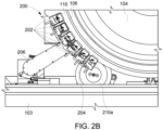
- FIGS. 2A-2B illustrate one exemplary embodiment of an ultrasonic testing system 200 for inspection of a train wheel 102
- the train wheel 102 includes a wheel disk 104, a running tread 106, and a wheel flange 110.
- the wheel disk 104 forms a center of the train wheel 102 and the running tread 106 forms a circumferential outer surface of the train wheel 102.
- the wheel flange 110 can be formed on one side of the train wheel 102 (e.g., an interior side) and extend radially outward from the running tread 106.
- the wheel disk 104 includes one or more holes therethrough. As shown, a primary hole 112 is positioned at about a center of the wheel disk 104 and can be configured for receipt of an axle 115 therethrough. One or more secondary holes 114 can be formed radially outward from the primary hole 112 and configured for coupling other components to the train wheel 102, such as brake disks (not shown).
- the ultrasonic testing system 200 can include one or more ultrasonic probes 202 and a probe positioning assembly 208 including a probe holder 204, a probe holder mount 206, and a lift and rotation unit 210. As shown, a predetermined number of ultrasonic probes 202 can be mechanically coupled to the probe holder 204 and oriented with respect to one another by the probe holder 204 (e.g., in an arcuate configuration mimicking a curvature of the running tread 106). Each probe holder 204 in turn can be coupled to the probe holder mount 206.
- the lift and rotation unit 210 can be configured to lift the train wheel 102 above the underlying rail 103 and rotate the train wheel 102 about an axis extending through the primary hole 112 (e.g., via one or more rotation wheels 210a).
- the probe holder mount 206 can be coupled to the probe holder 204 and it can be configured to position the ultrasonic probes 202 adjacent to or in contact with the running tread 106 for ultrasonic communication with the train wheel 102 while lifted. While not shown, an ultrasonic couplant fluid can be provided between the ultrasonic probes 202 and the train wheel 102 to facilitate ultrasonic communication.
- ultrasonic beams when ultrasonic beams pass through a material, they can reflect from surfaces of the material, such as interior defects (e.g., cracks, pores, etc.) and outer surfaces.
- Material features such as geometric boundaries and defects, can reflect ultrasonic beams in different ways. Some material features can reflect ultrasonic beams better than others, and the strength of the reflected ultrasonic beams can vary. Material features can also be at different distances from the ultrasonic probes and the time at which reflected ultrasonic beams reach the ultrasonic probes can vary. Measurements of the strength and time behavior of ultrasonic beams reflected from the train wheel 102 can be analyzed to determine the position and size of internal defects.
- FIG. 3A is a side view of a portion of the train wheel 102, illustrating ultrasonic testing system 200 in the form of ultrasonic testing system 300 which includes two sets of ultrasonic probes 302 for ultrasonic testing according to an existing technique.
- the ultrasonic probes 302 are positioned on the train wheel 102 (e.g., an outer circumferential surface of the running tread 106) and they can include one or more inspection ultrasonic probes (e.g., 304a, 304b) and a validation ultrasonic probe (e.g., 306).
- a corresponding cross-sectional front view of the train wheel 102 is illustrated in FIG. 3B .
- the ultrasonic testing system 300 can also include the probe holder 204, the probe holder mount 206, and a lift and rotation unit 210, which are omitted for clarity.
- Each of the ultrasonic probes 302a, 302b can include a single ultrasonic active element configured to generate and/or measure ultrasonic waves (also referred to as ultrasonic beams) for ultrasonic inspection of the train wheel 102 within an inspection area 310.
- the inspection area 310 is located between the primary hole 112 and the running tread 106.
- the inspection ultrasonic probes 304a, 304b can be configured to measure defects 308 (e.g., 1, 2, 3, 4) within the inspection area 310 by sending and receiving inspection ultrasonic signals 304s.
- the inspection ultrasonic probes 304a, 304b can be paired, one for transmitting and one for receiving, referred to as a "V-transmission configuration.” As shown in FIG.
- a first inspection ultrasonic probe 304a can be configured to emit an inspection ultrasonic signal 304s. If a defect 308 is present in the path of the inspection ultrasonic signal 304s, it can reflect from that defect 308 (e.g., 1, 2, 3) and be measured by a second inspection ultrasonic probe 304b.
- a single one of the inspection ultrasonic probes 304a, 304b can both generate and measure an inspection ultrasonic beam that is reflected from one of the defects 308, also referred to as direct scan.
- the second inspection ultrasonic probe 304b can generate an ultrasonic inspection signal 304s' that is reflected from one of the defects 308 (e.g., 4) within the inspection area 310 and measure the reflected ultrasonic inspection signal 304s'.
- analysis of the measured ultrasonic inspection signals 304s, 304s' can provide estimates of the size and location of one or more of the defects 308 (e.g., 1, 2, 3, 4) within the inspection area 310.
- the validation ultrasonic probe 306 is employed to validate the coupling of the inspection ultrasonic probes 304a, 304b.
- wheel disk geometries include features that reflect ultrasonic beams with defined, characteristic, and well-known reflection properties. Such features include, but are not limited to the convex intersection from the running tread 106 to the wheel disk 104. These features can be referred to herein as coupling validation geometries 312.
- the validation ultrasonic probe 306 is configured to generate and measure validation ultrasonic signals 306s reflected from coupling validation geometries 312. When the validation ultrasonic signals 306s measured by the validation ultrasonic probe 306 agree with an expected behavior, coupling can be considered to be good or validated. When the validation ultrasonic signals 306s measured by the validation ultrasonic probe 306 deviate from an expected behavior, coupling can be considered to be poor or not validated.
- the orientation of the inspection ultrasonic probes 304a, 304b and the validation ultrasonic probe 306 are different. That is, respective ones of the ultrasonic probes 302 cannot both measure defects 308 and perform validation.
- the need for a validation ultrasonic probe 306 separate from the inspection ultrasonic probes 304a, 304b can add additional cost and complexity to existing ultrasonic testing systems (e.g., ultrasonic testing system 300).
- Embodiments of the present disclosure provide improved systems and methods for ultrasonic testing.
- An improved ultrasonic testing system 400 can be similar to the ultrasonic testing system 200, including the probe holder 204, the probe holder mount 206, and the lift and rotation unit 210 of FIG. 2 .
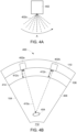
- the ultrasonic probes 202 are replaced with matrix array ultrasonic probes 402, also referred to as phased array ultrasonic probes, illustrated in FIG. 4A .
- a matrix array ultrasonic probe 402 can include two or more ultrasonic active elements. These ultrasonic active elements can be configured to generate and measure ultrasonic beams and they can be arranged in a predetermined pattern with respect to one another (e.g., a line, a circle, a grid, etc.).
- Each of the ultrasonic active elements can also be configured to generate ultrasonic beams that are varied in strength and/or time with respect to ultrasonic beams generated by the other ultrasonic active elements.
- the various ultrasonic beams can interfere with each other to produce a net ultrasonic beam 402s in a predetermined direction. This process can be repeated as necessary to sweep the ultrasonic beam 402s through an arc A of different predetermined directions.
- Exemplary embodiments of matrix array ultrasonic probes 402 can be found in U.S. Patent No. 9,244,043 .
- FIG. 4B is a side view of a portion of the train wheel 102.
- matrix array ultrasonic probes 402 can be positioned on or adjacent to the train wheel 102 (e.g., an outer circumferential surface of the running tread 106) for ultrasonic testing.
- a corresponding cross-sectional front view of the train wheel 102 is illustrated in FIG. 4C .
- Two matrix array ultrasonic probes 402a, 402b are illustrated and remaining portions of the improved ultrasonic testing system 400 are omitted for clarity.
- any number of matrix array probes can be employed without limit.
- the matrix array ultrasonic probes can be positioned on or adjacent to the wheel at a suitable location, such as an outer circumferential surface of the wheel.
- Each of the matrix array ultrasonic probes 402 are configured to acquire measurements for detection of defects 404 within an inspection area 406 and validation their ultrasonic coupling with respect to the train wheel 102.
- the inspection area 406 extends from the running tread 106 to the primary hole 112.
- the matrix array ultrasonic probes 402 are arranged in a V-transmission configuration.
- the matrix array ultrasonic probe 402a can be configured to generate an inspection ultrasonic signal 410s that is directed towards the inspection area 406. If the defect 404 is present in the path of the inspection ultrasonic signal 410s, the inspection ultrasonic signal 410s can reflect from the defect 404 and be measured by matrix array ultrasonic probe 402b.
- both of the matrix array ultrasonic probes 402a, 402b can also be configured to generate and measure a respective validation ultrasonic signal 412s reflected from a coupling validation geometry 414.
- the inspection ultrasonic signal 410s and the validation ultrasonic signal 412s can be emitted and reflected in different directions from each other.
- the coupling validation geometry 414 represents one or more features that reflect ultrasonic beams with defined, characteristic, and well-known reflection properties (e.g., features with convex radii). While V-transmission configurations have been discussed above, embodiments of the improved ultrasonic testing system can also employ matrix ultrasonic probes in a direct scan configuration, where each matrix ultrasonic probe both generates and measures inspection ultrasonic beams after reflection from a defect.
- the train wheel 102 can be lifted from an underlying surface (e.g., the rail 103) while the inspection ultrasonic signal 410s and the validation ultrasonic signal 412s are emitted and reflected.
- the train wheel 102 can also be rotated while lifted to facilitate inspection of the substantially the entire volume of the inspection area 406. In one aspect, rotation can be performed after measurement of reflected inspection ultrasonic signal 410s and validation ultrasonic signal 412s.
- rotation can be performed at a selected speed during emission of inspection ultrasonic signal 410s and validation ultrasonic signal 412s, reflection of reflected inspection ultrasonic signal 410s and validation ultrasonic signal 412s, and/or measurement of reflected inspection ultrasonic signal 410s and validation ultrasonic signal 412s.
- FIGS. 5A-5D illustrate front cross-sectional views of additional exemplary embodiments of train wheels 500, 502, 504, 506 having different additional coupling validation geometries 510, 512, 514, 516 and respective matrix array ultrasonic probes 402 positioned thereon for ultrasonic testing.
- the additional coupling validation geometries 510, 512, 514, 515 for each of the train wheels 500, 502, 504, 506 are circled for reference.
- additional coupling validation geometries 510, 512, 514, 516 can be present within the running tread 106, the wheel disk 104, or combinations thereof.
- embodiments of the matrix array ultrasonic probes 402 can direct additional validation ultrasonic signals 412s towards one or more of the coupling validation geometries 510, 512, 514, 516 of their respective train wheel 500, 502, 504, 506 in order to validate their coupling thereto. Further, as discussed above, the matrix array ultrasonic probes 402 can direct inspection ultrasonic signals 410s into the inspection area 406 for detection of defects 404.
- FIG. 6 illustrates an analysis system 600 of the improved ultrasonic testing system 400 configured for electronic communication with each of the matrix array ultrasonic probes 402.
- the analysis system 600 can include an analyzer 602, an annunciator 604, and a display device 606.
- the analyzer 602 can be any computing device employing a general purpose or application specific processor (e.g., processor 610) and can also include a memory 612.
- the processor 610 can include one or more processing devices, and the first memory 220 can include one or more tangible, non-transitory, machine-readable media collectively storing instructions executable by the first processor 216 to perform the methods and control actions described herein.
- Embodiments of the analyzer 602 can be implemented using analog electronic circuitry, digital electronic circuitry, and combinations thereof.
- the memory 612 can store a reference validation signal for each coupling validation geometry 414.
- the reference validation signal can represent a validation ultrasonic signal 412s measured under conditions of good coupling.
- the memory 612 can further store instructions and/or algorithms for determining whether the measured validation ultrasonic signal 412s reflected from a coupling validation geometry 414 matches a corresponding reference ultrasonic signal for that coupling validation geometry 414.
- a match can be determined when the strength of the measured validation ultrasonic signal 412s and the reference validation ultrasonic signal vary from one another by less than a predetermined threshold amount as a function of time.
- a match may not be determined when the strength of the measured validation ultrasonic signal 412s and the reference validation ultrasonic signal vary from one another by greater than the predetermined threshold amount as a function of time.
- the memory can store a reference validation signal strength for each validation coupling geometry.
- the reference validation signal strength can represent a threshold strength above which a validation ultrasonic signal can be considered to represent good coupling.
- the memory can further store instructions and/or algorithms for determining whether the measured validation ultrasonic signal reflected from a coupling validation geometry exhibits a strength greater than or equal to the reference validation signal strength for that coupling validation geometry.
- a measured validation ultrasonic signal having a strength greater than or equal to the reference validation signal strength can be considered to possess good coupling.
- a measured validation ultrasonic signal determined having a strength less than the reference validation signal strength can be considered to possess poor coupling.
- FIG 7 is a flow diagram illustrating an exemplary embodiment of a method 700 for ultrasonic inspection in which each of the matrix array ultrasonic probes 402 can be configured to both perform ultrasonic inspection of the train wheel 102 and validate its ultrasonic coupling with the train wheel 102.
- the method 700 is described below in connection with the improved ultrasonic testing system 400 of FIGS. 4A-6 .
- the method 700 includes operations 702-716.
- alternative embodiments of the method can include more operations than illustrated in FIG. 7 , and the operations can be performed in a different order than illustrated in FIG. 7 , insofar as falling under the scope of the claims.
- one or more matrix array ultrasonic probes 402 are positioned for ultrasonic communication with the train wheel 102.
- the matrix array ultrasonic probes 402 are positioned using the probe positioning assembly 208.
- the one or more matrix array ultrasonic probes 402 can be positioned on or adjacent to the running tread 106 of the train wheel 102.
- the one or more matrix array ultrasonic probes 402 can include at least two matrix array ultrasonic probes (e.g., 402a, 402b) positioned with respect to one another in a configuration that mimics a curvature of the running tread 106.
- each of the one or more matrix array ultrasonic probes 402 emit the validation ultrasonic signal 412s towards a coupling validation geometry (e.g., 414) within the train wheel 102 and measure the corresponding reflected validation ultrasonic signals 412s.
- the train wheel 102 includes one or more coupling validation geometries (e.g., 414).
- each of the matrix array ultrasonic probes 402 can be configured to sweep the emitted validation ultrasonic signal 412s through an arc of predetermined directions and measure a plurality of validation ultrasonic signals 412s after reflection from a plurality of coupling validation geometries 414.
- each of the matrix array ultrasonic probes 402 emits an ultrasonic inspection signal 410s towards the inspection area 406 of the train wheel 102. Similar to the validation ultrasonic signals 412s, the emitted inspection ultrasonic signals 410s can be swept through an arc of predetermined directions. In operation 710, at least one of the matrix array ultrasonic probes 402 can measure the emitted inspection ultrasonic signal 410s after reflection from a defect within the inspection area 406 (e.g., defect 404).
- each of the matrix array ultrasonic probes 402 that emits an inspection ultrasonic signal 410s can be configured to sweep the inspection ultrasonic signal 410s through an arc of predetermined directions, and each of the matrix array ultrasonic probes 402 that measures the reflected inspection ultrasonic signal 410s can be configured to measure a plurality of inspection ultrasonic signals 410s after reflection from a plurality of respective defects 404.
- the one or more matrix array ultrasonic probes 402 can include at least two matrix array ultrasonic probes (e.g., 402a, 402b).
- a first one of the at least two matrix array ultrasonic probes 402a can be configured to emit the inspection ultrasonic signal 410s towards the inspection area 406, and a second one of the at least two matrix array ultrasonic probes 402b can be configured to measure the inspection ultrasonic signal 410s reflected from a defect 404 (e.g., a V-transmission configuration).
- first matrix array ultrasonic probe 402a and the second matrix array ultrasonic probe 402b can each be configured to emit the inspection ultrasonic signal 410s and to measure its inspection ultrasonic signal 410s reflected from a defect 404 (e.g., a direct beam configuration).
- the manner in which the inspection ultrasonic signals 410s and validation ultrasonic signals 412s are generated can be chosen based upon the train wheel 102 under inspection. In general, a predefined number of inspection ultrasonic beams can be generated, followed by a validation ultrasonic signal, or vice versa. In one aspect, the inspection ultrasonic signals and validation ultrasonic signals can be alternatingly generated. In another aspect, a predetermined number of inspection ultrasonic signal can be generated (e.g., approximately 100,) followed by one or more validation ultrasonic signal. This cycle can be repeated or varied as necessary for the duration of ultrasonic testing.
- the analyzer 602 validate the ultrasonic coupling of the matrix array ultrasonic probes 402.
- the analyzer 602 receives a measured validation ultrasonic signal 412s and a measured inspection ultrasonic signal 410s (e.g., from matrix array ultrasonic probes 402).
- the analyzer 602 can determine that the measured validation ultrasonic signal 412s matches a reference validation ultrasonic signal.
- the reference validation ultrasonic signal 412 can be maintained by the memory 612 and the processor 610 can conduct a comparison of the two to determine a match.
- a match can be identified when the measured validation ultrasonic signal 412s and the reference validation ultrasonic signal differ by less than a threshold amount (e.g., on the basis of strength as a function of time).
- the analyzer 602 is configured to output a first notification signal 602s representing validation of the measured inspection ultrasonic signal 410s in operation 716.
- the analyzer 602 can be configured to output also a second notification signal 602s' representing invalidation of the measured inspection ultrasonic signal 410s in operation 716.
- the first and second notification signals 602s, 602s' can be received by the annunciator 604.
- the annunciator 604 can be configured to annunciate a first annunciation (e.g., audio, video, text, etc.) representing validation of the inspection ultrasonic signal 410s in response to receipt of the first notification signal 602s.
- the annunciator 604 can be configured to annunciate a second annunciation (e.g., audio, video, text, etc.) representing invalidation of the inspection ultrasonic signal 410s in response to receipt of the second notification signal 602s'.
- ultrasonic coupling validation can be provided for each of the matrix array ultrasonic probes. That is, unlike existing ultrasonic testing system, ultrasonic coupling between each matrix ultrasonic probe and a train wheel can be measured directly, rather than assumed based upon measurements from other ultrasonic probes. This direct validation can ensure that ultrasonic testing results are properly interpreted.
- the use of matrix array ultrasonic probes in an ultrasonic testing system can substantially minimize the risk that defects are missed due to erroneous interpretations of ultrasonic testing results.
- improved ultrasonic testing systems can be provided in which all ultrasonic probes are employed for detection of defects. That is in contrast to existing ultrasonic testing systems where some probes (e.g., validation ultrasonic probes) are employed solely for coupling validation and not defect detection. The absence of probes configured for different functions can reduce the complexity and cost of ultrasonic testing.
- the subject matter described herein can be implemented in analog electronic circuitry, digital electronic circuitry, and/or in computer software, firmware, or hardware, including the structural means disclosed in this specification and structural equivalents thereof, or in combinations of them.
- the subject matter described herein can be implemented as one or more computer program products, such as one or more computer programs tangibly embodied in an information carrier (e.g., in a machine-readable storage device), or embodied in a propagated signal, for execution by, or to control the operation of, data processing apparatus (e.g., a programmable processor, a computer, or multiple computers).
- a computer program (also known as a program, software, software application, or code) can be written in any form of programming language, including compiled or interpreted languages, and it can be deployed in any form, including as a stand-alone program or as a module, component, subroutine, or other unit suitable for use in a computing environment.
- a computer program does not necessarily correspond to a file.
- a program can be stored in a portion of a file that holds other programs or data, in a single file dedicated to the program in question, or in multiple coordinated files (e.g., files that store one or more modules, sub-programs, or portions of code).
- a computer program can be deployed to be executed on one computer or on multiple computers at one site or distributed across multiple sites and interconnected by a communication network.
- processors suitable for the execution of a computer program include, by way of example, both general and special purpose microprocessors, and any one or more processor of any kind of digital computer.
- a processor will receive instructions and data from a read-only memory or a random access memory or both.
- the essential elements of a computer are a processor for executing instructions and one or more memory devices for storing instructions and data.
- a computer will also include, or be operatively coupled to receive data from or transfer data to, or both, one or more mass storage devices for storing data, e.g., magnetic, magneto-optical disks, or optical disks.
- Information carriers suitable for embodying computer program instructions and data include all forms of non-volatile memory, including by way of example semiconductor memory devices, (e.g., EPROM, EEPROM, and flash memory devices); magnetic disks, (e.g., internal hard disks or removable disks); magneto-optical disks; and optical disks (e.g., CD and DVD disks).
- semiconductor memory devices e.g., EPROM, EEPROM, and flash memory devices
- magnetic disks e.g., internal hard disks or removable disks
- magneto-optical disks e.g., CD and DVD disks
- optical disks e.g., CD and DVD disks.
- the processor and the memory can be supplemented by, or incorporated in, special purpose logic circuitry.
- the subject matter described herein can be implemented on a computer having a display device, e.g., a CRT (cathode ray tube) or LCD (liquid crystal display) monitor, for displaying information to the user and a keyboard and a pointing device, (e.g., a mouse or a trackball), by which the user can provide input to the computer.
- a display device e.g., a CRT (cathode ray tube) or LCD (liquid crystal display) monitor
- a keyboard and a pointing device e.g., a mouse or a trackball
- Other kinds of devices can be used to provide for interaction with a user as well.
- feedback provided to the user can be any form of sensory feedback, (e.g., visual feedback, auditory feedback, or tactile feedback), and input from the user can be received in any form, including acoustic, speech, or tactile input.
- modules refers to computing software, firmware, hardware, and/or various combinations thereof. At a minimum, however, modules are not to be interpreted as software that is not implemented on hardware, firmware, or recorded on a non-transitory processor readable recordable storage medium (i.e., modules are not software per se ). Indeed “module” is to be interpreted to always include at least some physical, non-transitory hardware such as a part of a processor or computer. Two different modules can share the same physical hardware (e.g., two different modules can use the same processor and network interface). The modules described herein can be combined, integrated, separated, and/or duplicated to support various applications.
- a function described herein as being performed at a particular module can be performed at one or more other modules and/or by one or more other devices instead of or in addition to the function performed at the particular module.
- the modules can be implemented across multiple devices and/or other components local or remote to one another. Additionally, the modules can be moved from one device and added to another device, and/or can be included in both devices.
- the subject matter described herein can be implemented in a computing system that includes a back-end component (e.g., a data server), a middleware component (e.g., an application server), or a front-end component (e.g., a client computer having a graphical user interface or a web browser through which a user can interact with an implementation of the subject matter described herein), or any combination of such back-end, middleware, and front-end components.
- the components of the system can be interconnected by any form or medium of digital data communication, e.g., a communication network. Examples of communication networks include a local area network ("LAN”) and a wide area network (“WAN”), e.g., the Internet.
- LAN local area network
- WAN wide area network
- Approximating language may be applied to modify any quantitative representation that could permissibly vary without resulting in a change in the basic function to which it is related. Accordingly, a value modified by a term or terms, such as “about,” “approximately,” and “substantially,” are not to be limited to the precise value specified. In at least some instances, the approximating language may correspond to the precision of an instrument for measuring the value.
- range limitations may be combined and/or interchanged, such ranges are identified and include all the sub-ranges contained therein unless context or language indicates otherwise.
Landscapes
- Physics & Mathematics (AREA)
- Analytical Chemistry (AREA)
- General Health & Medical Sciences (AREA)
- Health & Medical Sciences (AREA)
- Life Sciences & Earth Sciences (AREA)
- Chemical & Material Sciences (AREA)
- Pathology (AREA)
- Biochemistry (AREA)
- Immunology (AREA)
- General Physics & Mathematics (AREA)
- Acoustics & Sound (AREA)
- Engineering & Computer Science (AREA)
- Signal Processing (AREA)
- Mechanical Engineering (AREA)
- Investigating Or Analyzing Materials By The Use Of Ultrasonic Waves (AREA)
Claims (19)
- Ultraschallprüfsystem (400) und ein zu prüfendes Rad (102), wobei das System umfasst:eine oder mehrere Matrixarray-Ultraschallsonden (402);eine Sondenpositionierungsanordnung (208), die so konfiguriert ist, dass sie eine mechanische Kopplung mit der einen oder den mehreren Matrixarray-Ultraschallsonden (402) herstellt und die eine oder die mehreren Matrixarray-Ultraschallsonden (402) für eine Ultraschallkommunikation mit dem Rad (102) positioniert, das eine Radscheibe (104), die eine Radmitte bildet, eine Lauffläche (106), die eine umlaufende Außenfläche des Rades bildet, und mindestens eine Kopplungsvalidierungsgeometrie (312) einschließt, die ein Merkmal aufweist, das Ultraschallstrahlen mit definierten, charakteristischen und bekannten Reflexionseigenschaften reflektiert;wobei die eine oder die mehreren Matrixarray-Ultraschallsonden (402) konfiguriert sind zum:Aussenden eines Validierungs-Ultraschallsignals (412s), das auf die Kopplungsvalidierungsgeometrie (312) innerhalb des Rades (102) gerichtet ist;Messen des ausgesendeten Validierungs-Ultraschallsignals nach der Reflexion von einer jeweiligen der mindestens einen Kopplungsvalidierungsgeometrie (312); undAussenden eines Ultraschallprüfsignals (410s) zum Messen eines Ultraschallprüfsignals, das von einem Defekt (404) reflektiert wird, der innerhalb eines Prüfbereichs (310) positioniert ist, der sich zwischen einem Hauptloch (112), das etwa in der Mitte der Radscheibe (104) positioniert ist, und der Lauffläche (106) des Rades befindet; undeinen Analysator (602), der konfiguriert ist zum:Empfangen des gemessenen Validierungs-Ultraschallsignals (412s) und des gemessenen Ultraschallprüfsignals (410s);Bestimmen, ob das gemessene Validierungs-Ultraschallsignal (412s) mit einem Referenzvalidierungssignal übereinstimmt; undAusgeben einer ersten Benachrichtigung, die eine Validierung des gemessenen Ultraschallprüfsignals (410s) unter der Voraussetzung darstellt, dass das gemessene Validierungssignal mit dem Referenzvalidierungssignal übereinstimmt;wobei die mindestens eine Kopplungsvalidierungsgeometrie (312) den konvexen Schnittpunkt von der Lauffläche (106) des Rades (102) mit der Radscheibe (104) des Rades (102) umfasst.
- System und Rad nach Anspruch 1, wobei der Analysator (602) ferner konfiguriert ist zum:Bestimmen, dass das gemessene Validierungs-Ultraschallsignal (412s) nicht mit dem Referenzvalidierungssignal übereinstimmt; undAusgeben einer zweiten Benachrichtigung, die die Ungültigkeit des gemessenen Ultraschallprüfsignals (410s) unter der Voraussetzung darstellt, dass das gemessene Validierungssignal nicht mit dem Referenzvalidierungssignal übereinstimmt.
- System und Rad nach Anspruch 1, wobei jede der Matrixarray-Ultraschallsonden (402) so konfiguriert ist, dass der ausgesendete Validierungs-Ultraschallstrahl (412s) einen Bogen mit vorgegebenen Richtungen durchläuft, und dass sie eine Vielzahl von Validierungs-Ultraschallsignalen nach der Reflexion von einer Vielzahl von jeweiligen Kopplungsvalidierungsgeometrien (312) misst.
- System und Rad nach Anspruch 1, wobei jede der Matrixarray-Ultraschallsonden (402) , die das Ultraschallprüfsignal aussendet, so konfiguriert ist, dass das Ultraschallprüfsignal einen Bogen mit vorgegebenen Richtungen durchläuft, und jede der Matrixarray-Ultraschallsonden (402), die den reflektierten Ultraschallprüfstrahl misst, so konfiguriert ist, dass sie eine Vielzahl von Ultraschallprüfsignalen nach der Reflexion von einer Vielzahl von jeweiligen Defekten misst.
- System und Rad nach Anspruch 1, umfassend einen Sondenhalter (204) und mindestens zwei Matrix-Ultraschallsonden (402), wobei der Sondenhalter (204) die mindestens zwei Matrixarray-Ultraschallsonden in einer Konfiguration relativ zueinander positioniert, die eine Krümmung einer Lauffläche des Rades nachahmt.
- System und Rad nach Anspruch 5, wobei eine erste der mindestens zwei Matrix-Ultraschallsonden (402) so konfiguriert ist, dass sie das Ultraschallprüfsignal in Richtung des Prüfbereichs aussendet, und eine zweite der mindestens zwei Matrixarray-Ultraschallsonden so konfiguriert ist, dass sie das Ultraschallprüfsignal misst, das von einem Defekt innerhalb des Prüfbereichs reflektiert wird.
- System und Rad nach Anspruch 5, wobei eine erste der mindestens zwei Matrix-Ultraschallsonden und eine zweite der mindestens zwei Ultraschallsonden jeweils so konfiguriert sind, dass sie sowohl das Ultraschallprüfsignal in Richtung des Prüfbereichs aussenden als auch das von einem Defekt innerhalb des Prüfbereichs reflektierte Ultraschallprüfsignal messen.
- System und Rad nach Anspruch 1, wobei die Sondenpositionierungsanordnung (208) so konfiguriert ist, dass sie das Rad (102) reversibel über eine darunter liegende Oberfläche hebt und das Rad (102) in angehobenem Zustand dreht.
- System und Rad nach Anspruch 2, ferner umfassend einen Melder (604), der mit dem Analysator (602) in Verbindung steht und so konfiguriert ist, dass er als Reaktion auf den Empfang der ersten Benachrichtigung eine erste Meldung meldet, die die Validierung des Ultraschallprüfsignals darstellt, und als Reaktion auf den Empfang der zweiten Benachrichtigung eine zweite Meldung meldet, die die Ungültigkeit des Ultraschallprüfsignals darstellt.
- Verfahren (700) zum Ultraschallprüfen eines Rades (102), wobei das Verfahren umfasst:Positionieren (702) von einer oder mehreren Matrixarray-Ultraschallsonden (402) zur Ultraschallkommunikation mit dem Rad (102), das eine Radscheibe (104), die eine Radmitte bildet, eine Lauffläche (106), die eine umlaufende Außenfläche des Rades bildet, und mindestens eine Kopplungsvalidierungsgeometrie (312) einschließt;Aussenden (704) eines Validierungs-Ultraschallsignals (412s) durch die eine oder die mehreren Matrixarray-Ultraschallsonden (402), das auf die Kopplungsvalidierungsgeometrie (312) gerichtet ist und ein Merkmal aufweist, das Ultraschallstrahlen mit definierten, charakteristischen und bekannten Reflexionseigenschaften innerhalb des Rades (102) reflektiert;Messen (706), durch die eine oder die mehreren Matrixarray-Ultraschallsonden (402), des ausgesendeten Validierungs-Ultraschallsignals nach der Reflexion von einer jeweiligen der mindestens einen Kopplungsvalidierungsgeometrie (312);Aussenden (708), durch die mindestens eine der Matrixarray-Ultraschallsonden (402), eines Ultraschallprüfsignals (410s) in Richtung eines Prüfbereichs (310), der sich zwischen einem Hauptloch (112), das etwa in der Mitte der Radscheibe (104) positioniert ist, und der Lauffläche (106) des Rades (102) befindet;Messen (710), durch mindestens eine der Matrixarray-Ultraschallsonden (402), des Ultraschallprüfsignals nach der Reflexion von einem Defekt (404), der innerhalb des Prüfbereichs positioniert ist;Empfangen (712) des gemessenen Validierungs-Ultraschallsignals und des gemessenen Ultraschallprüfsignals durch einen Analysator (602), der mit jeder der einen oder mehreren Matrixarray-Ultraschallsonden (402) in Verbindung steht;Bestimmen (714), durch den Analysator (602), ob das gemessene Validierungs-Ultraschallsignal mit einem Referenzvalidierungssignal übereinstimmt; undAusgeben (716), durch den Analysator (602), einer ersten Benachrichtigung, die eine Validierung des gemessenen Ultraschallprüfsignals (410s) unter der Voraussetzung darstellt, dass das gemessene Validierungssignal mit dem Referenzvalidierungssignal übereinstimmt;wobei die mindestens eine Kopplungsvalidierungsgeometrie (312) den konvexen Schnittpunkt von der Lauffläche (106) des Rades (102) mit der Radscheibe (104) des Rades (102) umfasst.
- Verfahren nach Anspruch 10, ferner umfassend das Bestimmen durch den Analysator (602), dass das gemessene Validierungs-Ultraschallsignal nicht mit dem Referenzvalidierungssignal übereinstimmt; und
Ausgeben einer zweiten Benachrichtigung, die die Ungültigkeit des gemessenen Ultraschallprüfsignals unter der Voraussetzung darstellt, dass das gemessene Validierungssignal nicht mit dem Referenzvalidierungssignal übereinstimmt. - Verfahren nach Anspruch 10, wobei jede der Matrixarray-Ultraschallsonden (402) so konfiguriert ist, dass der emittierte Validierungs-Ultraschallstrahl einen Bogen mit vorgegebenen Richtungen durchläuft, und dass sie eine Vielzahl von Validierungs-Ultraschallsignalen nach der Reflexion von einer Vielzahl entsprechender Kopplungsvalidierungsgeometrien misst.
- Verfahren nach Anspruch 10, wobei jede der Matrixarray-Ultraschallsonden (402), die das Ultraschallprüfsignal aussenden, so konfiguriert ist, dass das Ultraschallprüfsignal einen Bogen mit vorgegebenen Richtungen durchläuft, und wobei jede der Matrixarray-Ultraschallsonden, die den reflektierten Ultraschallprüfstrahl messen, so konfiguriert ist, dass sie eine Vielzahl von Ultraschallprüfsignalen nach der Reflexion von einer Vielzahl von jeweiligen Defekten innerhalb des Prüfbereichs misst.
- Verfahren nach Anspruch 10, wobei die mindestens eine Matrixarray-Ultraschallsonde mindestens zwei Matrixarray-Ultraschallsonden umfasst und wobei die mindestens zwei Matrixarray-Ultraschallsonden in einer Konfiguration relativ zueinander positioniert sind, die eine Krümmung einer Lauffläche des Rades (102) nachahmt.
- Verfahren nach Anspruch 14, wobei eine erste der mindestens zwei Matrix-Ultraschallsonden (402) so konfiguriert ist, dass sie das Ultraschallprüfsignal in Richtung des Prüfbereichs aussendet, und eine zweite der mindestens zwei Matrixarray-Ultraschallsonden so konfiguriert ist, dass sie das Ultraschallprüfsignal misst, das von einem Defekt innerhalb des Prüfbereichs reflektiert wird.
- Verfahren nach Anspruch 14, wobei eine erste der mindestens zwei Matrix-Ultraschallsonden und eine zweite der mindestens zwei Ultraschallsonden jeweils so konfiguriert sind, dass sie sowohl das Ultraschallprüfsignal in Richtung des Prüfbereichs aussenden als auch das von einem Defekt (404) innerhalb des Prüfbereichs reflektierte Ultraschallprüfsignal messen.
- Verfahren nach Anspruch 10, wobei die eine oder die mehreren Matrixarray-Ultraschallsonden (402) in Bezug auf das Rad (102) positioniert werden, während das Rad über eine darunter liegende Oberfläche gehoben wird.
- Verfahren nach Anspruch 17, ferner umfassend das Drehen des Rades (102) im angehobenen Zustand und nachdem jede Matrixarray-Ultraschallsonde (402) ihr ausgesendetes Validierungs-Ultraschallsignal gemessen und ihr Ultraschallprüfsignal ausgesendet und/oder gemessen hat.
- Verfahren nach Anspruch 10, wobei das Rad (102) ein Eisenbahnrad ist.
Applications Claiming Priority (2)
| Application Number | Priority Date | Filing Date | Title |
|---|---|---|---|
| US201762571448P | 2017-10-12 | 2017-10-12 | |
| PCT/US2018/055639 WO2019075347A1 (en) | 2017-10-12 | 2018-10-12 | ULTRASONIC TEST INSPECTION WITH COUPLING VALIDATION |
Publications (3)
| Publication Number | Publication Date |
|---|---|
| EP3695221A1 EP3695221A1 (de) | 2020-08-19 |
| EP3695221A4 EP3695221A4 (de) | 2021-06-02 |
| EP3695221B1 true EP3695221B1 (de) | 2025-02-19 |
Family
ID=66101084
Family Applications (1)
| Application Number | Title | Priority Date | Filing Date |
|---|---|---|---|
| EP18866404.9A Active EP3695221B1 (de) | 2017-10-12 | 2018-10-12 | Inspektion mittels ultraschalltest mit kopplungsvalidierung |
Country Status (5)
| Country | Link |
|---|---|
| US (1) | US20210223210A1 (de) |
| EP (1) | EP3695221B1 (de) |
| CN (1) | CN111344565A (de) |
| ES (1) | ES3018412T3 (de) |
| WO (1) | WO2019075347A1 (de) |
Families Citing this family (7)
| Publication number | Priority date | Publication date | Assignee | Title |
|---|---|---|---|---|
| EP3739330B1 (de) * | 2019-05-13 | 2024-12-11 | Baker Hughes Digital Solutions GmbH | Hochgeschwindigkeitsschienenradprüfung während des betriebs |
| US11474083B2 (en) * | 2020-01-03 | 2022-10-18 | The Boeing Company | Metrology qualification of non-destructive inspection systems |
| US11280765B2 (en) * | 2020-03-31 | 2022-03-22 | Baker Hughes Oilfield Operations Llc | Methods and devices for ultrasonic nondestructive testing devices |
| CN113984900B (zh) * | 2021-10-12 | 2023-10-03 | 北京福泽润慧科技有限公司 | 一种新能源风力发电用电极检测系统 |
| CN114624336B (zh) * | 2022-05-16 | 2022-09-02 | 四川升拓检测技术股份有限公司 | 基于轮式隔音的冲击回波声频法的信号检测装置及方法 |
| IT202400000771A1 (it) * | 2024-01-17 | 2025-07-17 | Img Ultrasuoni S R L | Dispositivo per il controllo degli assili dei treni |
| CN117949516A (zh) * | 2024-03-22 | 2024-04-30 | 山西天和盛环境检测股份有限公司 | 一种水体检测装置 |
Family Cites Families (20)
| Publication number | Priority date | Publication date | Assignee | Title |
|---|---|---|---|---|
| DE2753472A1 (de) * | 1977-11-28 | 1979-05-31 | Mannesmann Ag | Verfahren zur automatischen eigenueberwachung von zerstoerungsfreien pruefanlagen |
| JPH02132368A (ja) * | 1988-11-14 | 1990-05-21 | Fuji Electric Co Ltd | 超音波探触子のカップリングチェック法 |
| WO1990013814A1 (en) * | 1989-05-01 | 1990-11-15 | Hamersley Iron Pty. Limited | Ultrasonic wheel testing |
| DE59605143D1 (de) * | 1995-09-29 | 2000-06-08 | Siemens Ag | Verfahren und vorrichtung zur ultraschallprüfung von auf wellen aufgeschrumpften scheibenkörpern mit unbekannter kontur |
| US5864065A (en) * | 1997-11-25 | 1999-01-26 | Amsted Industries Incorporated | Test apparatus for a railway wheel |
| DE19833027C1 (de) * | 1998-07-23 | 2000-03-09 | Siemens Ag | Verfahren und Vorrichtung zum Prüfen eines Eisenbahnrads |
| DE19834587C1 (de) * | 1998-07-31 | 2000-04-20 | Siemens Ag | Verfahren und Vorrichtung zur Detektion eines Risses in einem Eisenbahnrad |
| WO2001098769A1 (de) * | 2000-06-20 | 2001-12-27 | Fraunhofer Gesellschaft Zur Förderung Der Angewandten Forschung E. V. | Vorrichtung und verfahren zur prüfung eines eisenbahnrades |
| JP4699242B2 (ja) * | 2006-02-28 | 2011-06-08 | 三菱重工業株式会社 | 超音波探触子のカップリングチェック方法、及びコンピュータプログラム |
| JP5010944B2 (ja) * | 2007-02-28 | 2012-08-29 | 株式会社東芝 | 超音波探傷装置 |
| JP5043627B2 (ja) * | 2007-12-14 | 2012-10-10 | 東京計器株式会社 | レール底部腐食量測定装置及び測定方法 |
| CN101666781B (zh) * | 2009-09-14 | 2011-07-27 | 成都主导科技有限责任公司 | 一种机车车辆车轮轮辐缺陷超声波检测装置 |
| KR101151732B1 (ko) * | 2009-12-10 | 2012-06-15 | 주식회사 에코마이스터 | 철도차량 차륜 내부 크랙 확인용 탐상장치 및 이를 구비한 차륜 재생장치 |
| CN103472138B (zh) * | 2013-09-25 | 2017-01-11 | 北京新联铁科技股份有限公司 | 一种轨道车辆车轮轮辋与踏面探伤探头组件系统 |
| CN103884773B (zh) * | 2014-02-20 | 2016-04-20 | 马钢(集团)控股有限公司 | 一种车轮轮辋自动超声波探伤方法 |
| JP6274957B2 (ja) * | 2014-04-22 | 2018-02-07 | 株式会社神戸製鋼所 | 斜角超音波探触子のカップリングモニタ方法 |
| DE102014119056A1 (de) * | 2014-12-18 | 2016-06-23 | Ge Sensing & Inspection Technologies Gmbh | Verfahren zur Detektion eines Fehlers wie eines Risses in einer Region-of-Interest in einem um eine Rotationsachse drehbaren Eisenbahnrad sowie Vorrichtung hierzu |
| DE102015108720A1 (de) * | 2015-06-02 | 2016-07-14 | Areva Gmbh | Ultraschall-Prüfvorrichtung und Verfahren zur zerstörungsfreien Prüfung eines Rades und einer Radscheibe |
| ES2929398T3 (es) * | 2015-07-07 | 2022-11-29 | Baker Hughes Holdings Llc | Método y sistema para inspeccionar una rueda de carril con sondas de matriz en fase |
| CN105606708B (zh) * | 2015-11-10 | 2019-04-09 | 南京拓控信息科技有限公司 | 一种列车车轮便携式探伤系统的检测方法 |
-
2018
- 2018-10-12 CN CN201880073228.XA patent/CN111344565A/zh active Pending
- 2018-10-12 ES ES18866404T patent/ES3018412T3/es active Active
- 2018-10-12 EP EP18866404.9A patent/EP3695221B1/de active Active
- 2018-10-12 WO PCT/US2018/055639 patent/WO2019075347A1/en not_active Ceased
- 2018-10-12 US US16/755,291 patent/US20210223210A1/en not_active Abandoned
Also Published As
| Publication number | Publication date |
|---|---|
| US20210223210A1 (en) | 2021-07-22 |
| ES3018412T3 (es) | 2025-05-16 |
| EP3695221A1 (de) | 2020-08-19 |
| CN111344565A (zh) | 2020-06-26 |
| EP3695221A4 (de) | 2021-06-02 |
| WO2019075347A1 (en) | 2019-04-18 |
Similar Documents
| Publication | Publication Date | Title |
|---|---|---|
| US20210223210A1 (en) | Ultrasonic testing inspection with coupling validation | |
| US9950715B2 (en) | Air-coupled ultrasonic inspection of rails | |
| US10648951B2 (en) | Classification of ultrasonic indications using pattern recognition | |
| US11353430B2 (en) | Phased array probe and method for testing a spot-weld | |
| US20120191377A1 (en) | Method and device for ultrasonic testing | |
| US20110041612A1 (en) | Pipeline inspection apparatus and method | |
| JP2011027571A (ja) | 配管減肉検査装置および配管減肉検査方法 | |
| EP2880435B1 (de) | Verfahren und system zur bestimmung der position von geometrischen merkmalen bei objekten | |
| US20210293757A1 (en) | Ndt data referencing system | |
| Zhang et al. | Strategies for guided acoustic wave inspection using mobile robots | |
| EP4012401B1 (de) | Ausrichtung einer ultraschallsonde mittels ultraschallsignalen | |
| JP6594608B2 (ja) | 超音波検出方法及び超音波分析方法 | |
| US11371964B2 (en) | Condition monitoring of ultrasonic transducers and probes | |
| US11002711B2 (en) | Detection system, detection method, and server device | |
| EP3739330B1 (de) | Hochgeschwindigkeitsschienenradprüfung während des betriebs | |
| WO2023091889A1 (en) | Display adjustment in visual representation of ultrasonic measurement | |
| EP4127698B1 (de) | Verfahren und vorrichtungen für zerstörungsfreie ultraschalltestvorrichtungen | |
| US20240319140A1 (en) | Transmission angle calibration | |
| EP4246140A1 (de) | Softwarebasierte unterstützung für zerstörungsfreie inspektion | |
| US11579120B2 (en) | Colored defect detection curves | |
| EP3695220B1 (de) | Ultraschallwinkelstrahlsonde mit mechanischer seitenverstellung | |
| WO2024228944A1 (en) | Systems and methods for determining the ultrasonic testing (ut) testability of defects in a weld |
Legal Events
| Date | Code | Title | Description |
|---|---|---|---|
| STAA | Information on the status of an ep patent application or granted ep patent |
Free format text: STATUS: THE INTERNATIONAL PUBLICATION HAS BEEN MADE |
|
| PUAI | Public reference made under article 153(3) epc to a published international application that has entered the european phase |
Free format text: ORIGINAL CODE: 0009012 |
|
| STAA | Information on the status of an ep patent application or granted ep patent |
Free format text: STATUS: REQUEST FOR EXAMINATION WAS MADE |
|
| 17P | Request for examination filed |
Effective date: 20200507 |
|
| AK | Designated contracting states |
Kind code of ref document: A1 Designated state(s): AL AT BE BG CH CY CZ DE DK EE ES FI FR GB GR HR HU IE IS IT LI LT LU LV MC MK MT NL NO PL PT RO RS SE SI SK SM TR |
|
| AX | Request for extension of the european patent |
Extension state: BA ME |
|
| DAV | Request for validation of the european patent (deleted) | ||
| DAX | Request for extension of the european patent (deleted) | ||
| A4 | Supplementary search report drawn up and despatched |
Effective date: 20210506 |
|
| RIC1 | Information provided on ipc code assigned before grant |
Ipc: G01N 29/44 20060101AFI20210429BHEP Ipc: G01N 29/24 20060101ALI20210429BHEP Ipc: G01N 29/36 20060101ALI20210429BHEP Ipc: B61K 9/12 20060101ALI20210429BHEP Ipc: G01N 29/04 20060101ALI20210429BHEP Ipc: G01N 29/30 20060101ALI20210429BHEP |
|
| P01 | Opt-out of the competence of the unified patent court (upc) registered |
Effective date: 20230526 |
|
| STAA | Information on the status of an ep patent application or granted ep patent |
Free format text: STATUS: EXAMINATION IS IN PROGRESS |
|
| 17Q | First examination report despatched |
Effective date: 20230912 |
|
| RAP3 | Party data changed (applicant data changed or rights of an application transferred) |
Owner name: BAKER HUGHES ENERGY SERVICES LLC |
|
| GRAP | Despatch of communication of intention to grant a patent |
Free format text: ORIGINAL CODE: EPIDOSNIGR1 |
|
| STAA | Information on the status of an ep patent application or granted ep patent |
Free format text: STATUS: GRANT OF PATENT IS INTENDED |
|
| INTG | Intention to grant announced |
Effective date: 20241126 |
|
| GRAS | Grant fee paid |
Free format text: ORIGINAL CODE: EPIDOSNIGR3 |
|
| GRAA | (expected) grant |
Free format text: ORIGINAL CODE: 0009210 |
|
| STAA | Information on the status of an ep patent application or granted ep patent |
Free format text: STATUS: THE PATENT HAS BEEN GRANTED |
|
| AK | Designated contracting states |
Kind code of ref document: B1 Designated state(s): AL AT BE BG CH CY CZ DE DK EE ES FI FR GB GR HR HU IE IS IT LI LT LU LV MC MK MT NL NO PL PT RO RS SE SI SK SM TR |
|
| RAP3 | Party data changed (applicant data changed or rights of an application transferred) |
Owner name: BAKER HUGHES ENERGY SERVICES LLC |
|
| REG | Reference to a national code |
Ref country code: GB Ref legal event code: FG4D |
|
| REG | Reference to a national code |
Ref country code: CH Ref legal event code: EP |
|
| REG | Reference to a national code |
Ref country code: IE Ref legal event code: FG4D |
|
| REG | Reference to a national code |
Ref country code: DE Ref legal event code: R096 Ref document number: 602018079423 Country of ref document: DE |
|
| REG | Reference to a national code |
Ref country code: ES Ref legal event code: FG2A Ref document number: 3018412 Country of ref document: ES Kind code of ref document: T3 Effective date: 20250516 |
|
| REG | Reference to a national code |
Ref country code: NL Ref legal event code: MP Effective date: 20250219 |
|
| PG25 | Lapsed in a contracting state [announced via postgrant information from national office to epo] |
Ref country code: RS Free format text: LAPSE BECAUSE OF FAILURE TO SUBMIT A TRANSLATION OF THE DESCRIPTION OR TO PAY THE FEE WITHIN THE PRESCRIBED TIME-LIMIT Effective date: 20250519 |
|
| PG25 | Lapsed in a contracting state [announced via postgrant information from national office to epo] |
Ref country code: FI Free format text: LAPSE BECAUSE OF FAILURE TO SUBMIT A TRANSLATION OF THE DESCRIPTION OR TO PAY THE FEE WITHIN THE PRESCRIBED TIME-LIMIT Effective date: 20250219 |
|
| PG25 | Lapsed in a contracting state [announced via postgrant information from national office to epo] |
Ref country code: PL Free format text: LAPSE BECAUSE OF FAILURE TO SUBMIT A TRANSLATION OF THE DESCRIPTION OR TO PAY THE FEE WITHIN THE PRESCRIBED TIME-LIMIT Effective date: 20250219 |
|
| REG | Reference to a national code |
Ref country code: LT Ref legal event code: MG9D |
|
| PG25 | Lapsed in a contracting state [announced via postgrant information from national office to epo] |
Ref country code: IS Free format text: LAPSE BECAUSE OF FAILURE TO SUBMIT A TRANSLATION OF THE DESCRIPTION OR TO PAY THE FEE WITHIN THE PRESCRIBED TIME-LIMIT Effective date: 20250619 Ref country code: NO Free format text: LAPSE BECAUSE OF FAILURE TO SUBMIT A TRANSLATION OF THE DESCRIPTION OR TO PAY THE FEE WITHIN THE PRESCRIBED TIME-LIMIT Effective date: 20250519 |
|
| PG25 | Lapsed in a contracting state [announced via postgrant information from national office to epo] |
Ref country code: NL Free format text: LAPSE BECAUSE OF FAILURE TO SUBMIT A TRANSLATION OF THE DESCRIPTION OR TO PAY THE FEE WITHIN THE PRESCRIBED TIME-LIMIT Effective date: 20250219 |
|
| PG25 | Lapsed in a contracting state [announced via postgrant information from national office to epo] |
Ref country code: HR Free format text: LAPSE BECAUSE OF FAILURE TO SUBMIT A TRANSLATION OF THE DESCRIPTION OR TO PAY THE FEE WITHIN THE PRESCRIBED TIME-LIMIT Effective date: 20250219 |
|
| PG25 | Lapsed in a contracting state [announced via postgrant information from national office to epo] |
Ref country code: PT Free format text: LAPSE BECAUSE OF FAILURE TO SUBMIT A TRANSLATION OF THE DESCRIPTION OR TO PAY THE FEE WITHIN THE PRESCRIBED TIME-LIMIT Effective date: 20250620 Ref country code: LV Free format text: LAPSE BECAUSE OF FAILURE TO SUBMIT A TRANSLATION OF THE DESCRIPTION OR TO PAY THE FEE WITHIN THE PRESCRIBED TIME-LIMIT Effective date: 20250219 |
|
| PG25 | Lapsed in a contracting state [announced via postgrant information from national office to epo] |
Ref country code: BG Free format text: LAPSE BECAUSE OF FAILURE TO SUBMIT A TRANSLATION OF THE DESCRIPTION OR TO PAY THE FEE WITHIN THE PRESCRIBED TIME-LIMIT Effective date: 20250219 Ref country code: GR Free format text: LAPSE BECAUSE OF FAILURE TO SUBMIT A TRANSLATION OF THE DESCRIPTION OR TO PAY THE FEE WITHIN THE PRESCRIBED TIME-LIMIT Effective date: 20250520 |
|
| REG | Reference to a national code |
Ref country code: AT Ref legal event code: MK05 Ref document number: 1768710 Country of ref document: AT Kind code of ref document: T Effective date: 20250219 |
|
| PG25 | Lapsed in a contracting state [announced via postgrant information from national office to epo] |
Ref country code: SE Free format text: LAPSE BECAUSE OF FAILURE TO SUBMIT A TRANSLATION OF THE DESCRIPTION OR TO PAY THE FEE WITHIN THE PRESCRIBED TIME-LIMIT Effective date: 20250219 |
|
| PG25 | Lapsed in a contracting state [announced via postgrant information from national office to epo] |
Ref country code: SM Free format text: LAPSE BECAUSE OF FAILURE TO SUBMIT A TRANSLATION OF THE DESCRIPTION OR TO PAY THE FEE WITHIN THE PRESCRIBED TIME-LIMIT Effective date: 20250219 |
|
| PG25 | Lapsed in a contracting state [announced via postgrant information from national office to epo] |
Ref country code: DK Free format text: LAPSE BECAUSE OF FAILURE TO SUBMIT A TRANSLATION OF THE DESCRIPTION OR TO PAY THE FEE WITHIN THE PRESCRIBED TIME-LIMIT Effective date: 20250219 |
|
| PGFP | Annual fee paid to national office [announced via postgrant information from national office to epo] |
Ref country code: IT Payment date: 20250923 Year of fee payment: 8 |
|
| PG25 | Lapsed in a contracting state [announced via postgrant information from national office to epo] |
Ref country code: AT Free format text: LAPSE BECAUSE OF FAILURE TO SUBMIT A TRANSLATION OF THE DESCRIPTION OR TO PAY THE FEE WITHIN THE PRESCRIBED TIME-LIMIT Effective date: 20250219 |
|
| PGFP | Annual fee paid to national office [announced via postgrant information from national office to epo] |
Ref country code: FR Payment date: 20250923 Year of fee payment: 8 |
|
| PG25 | Lapsed in a contracting state [announced via postgrant information from national office to epo] |
Ref country code: EE Free format text: LAPSE BECAUSE OF FAILURE TO SUBMIT A TRANSLATION OF THE DESCRIPTION OR TO PAY THE FEE WITHIN THE PRESCRIBED TIME-LIMIT Effective date: 20250219 Ref country code: CZ Free format text: LAPSE BECAUSE OF FAILURE TO SUBMIT A TRANSLATION OF THE DESCRIPTION OR TO PAY THE FEE WITHIN THE PRESCRIBED TIME-LIMIT Effective date: 20250219 |
|
| PG25 | Lapsed in a contracting state [announced via postgrant information from national office to epo] |
Ref country code: RO Free format text: LAPSE BECAUSE OF FAILURE TO SUBMIT A TRANSLATION OF THE DESCRIPTION OR TO PAY THE FEE WITHIN THE PRESCRIBED TIME-LIMIT Effective date: 20250219 |
|
| PG25 | Lapsed in a contracting state [announced via postgrant information from national office to epo] |
Ref country code: SK Free format text: LAPSE BECAUSE OF FAILURE TO SUBMIT A TRANSLATION OF THE DESCRIPTION OR TO PAY THE FEE WITHIN THE PRESCRIBED TIME-LIMIT Effective date: 20250219 |
|
| REG | Reference to a national code |
Ref country code: DE Ref legal event code: R097 Ref document number: 602018079423 Country of ref document: DE |
|
| PLBE | No opposition filed within time limit |
Free format text: ORIGINAL CODE: 0009261 |
|
| STAA | Information on the status of an ep patent application or granted ep patent |
Free format text: STATUS: NO OPPOSITION FILED WITHIN TIME LIMIT |
|
| PGFP | Annual fee paid to national office [announced via postgrant information from national office to epo] |
Ref country code: DE Payment date: 20250923 Year of fee payment: 8 |
|
| 26N | No opposition filed |
Effective date: 20251120 |
|
| PGFP | Annual fee paid to national office [announced via postgrant information from national office to epo] |
Ref country code: ES Payment date: 20251103 Year of fee payment: 8 |