EP3695094B1 - Überspannungsschutzsystem einer steigleitung - Google Patents
Überspannungsschutzsystem einer steigleitung Download PDFInfo
- Publication number
- EP3695094B1 EP3695094B1 EP18865782.9A EP18865782A EP3695094B1 EP 3695094 B1 EP3695094 B1 EP 3695094B1 EP 18865782 A EP18865782 A EP 18865782A EP 3695094 B1 EP3695094 B1 EP 3695094B1
- Authority
- EP
- European Patent Office
- Prior art keywords
- flexible tubing
- riser
- well
- pressure
- liquid
- Prior art date
- Legal status (The legal status is an assumption and is not a legal conclusion. Google has not performed a legal analysis and makes no representation as to the accuracy of the status listed.)
- Active
Links
Images

Classifications
-
- E—FIXED CONSTRUCTIONS
- E21—EARTH OR ROCK DRILLING; MINING
- E21B—EARTH OR ROCK DRILLING; OBTAINING OIL, GAS, WATER, SOLUBLE OR MELTABLE MATERIALS OR A SLURRY OF MINERALS FROM WELLS
- E21B43/00—Methods or apparatus for obtaining oil, gas, water, soluble or meltable materials or a slurry of minerals from wells
- E21B43/34—Arrangements for separating materials produced by the well
- E21B43/38—Arrangements for separating materials produced by the well in the well
-
- E—FIXED CONSTRUCTIONS
- E21—EARTH OR ROCK DRILLING; MINING
- E21B—EARTH OR ROCK DRILLING; OBTAINING OIL, GAS, WATER, SOLUBLE OR MELTABLE MATERIALS OR A SLURRY OF MINERALS FROM WELLS
- E21B43/00—Methods or apparatus for obtaining oil, gas, water, soluble or meltable materials or a slurry of minerals from wells
- E21B43/01—Methods or apparatus for obtaining oil, gas, water, soluble or meltable materials or a slurry of minerals from wells specially adapted for obtaining from underwater installations
-
- E—FIXED CONSTRUCTIONS
- E21—EARTH OR ROCK DRILLING; MINING
- E21B—EARTH OR ROCK DRILLING; OBTAINING OIL, GAS, WATER, SOLUBLE OR MELTABLE MATERIALS OR A SLURRY OF MINERALS FROM WELLS
- E21B37/00—Methods or apparatus for cleaning boreholes or wells
-
- E—FIXED CONSTRUCTIONS
- E21—EARTH OR ROCK DRILLING; MINING
- E21B—EARTH OR ROCK DRILLING; OBTAINING OIL, GAS, WATER, SOLUBLE OR MELTABLE MATERIALS OR A SLURRY OF MINERALS FROM WELLS
- E21B17/00—Drilling rods or pipes; Flexible drill strings; Kellies; Drill collars; Sucker rods; Cables; Casings; Tubings
- E21B17/01—Risers
-
- E—FIXED CONSTRUCTIONS
- E21—EARTH OR ROCK DRILLING; MINING
- E21B—EARTH OR ROCK DRILLING; OBTAINING OIL, GAS, WATER, SOLUBLE OR MELTABLE MATERIALS OR A SLURRY OF MINERALS FROM WELLS
- E21B17/00—Drilling rods or pipes; Flexible drill strings; Kellies; Drill collars; Sucker rods; Cables; Casings; Tubings
- E21B17/20—Flexible or articulated drilling pipes, e.g. flexible or articulated rods, pipes or cables
-
- E—FIXED CONSTRUCTIONS
- E21—EARTH OR ROCK DRILLING; MINING
- E21B—EARTH OR ROCK DRILLING; OBTAINING OIL, GAS, WATER, SOLUBLE OR MELTABLE MATERIALS OR A SLURRY OF MINERALS FROM WELLS
- E21B43/00—Methods or apparatus for obtaining oil, gas, water, soluble or meltable materials or a slurry of minerals from wells
- E21B43/12—Methods or apparatus for controlling the flow of the obtained fluid to or in wells
- E21B43/121—Lifting well fluids
-
- E—FIXED CONSTRUCTIONS
- E21—EARTH OR ROCK DRILLING; MINING
- E21B—EARTH OR ROCK DRILLING; OBTAINING OIL, GAS, WATER, SOLUBLE OR MELTABLE MATERIALS OR A SLURRY OF MINERALS FROM WELLS
- E21B43/00—Methods or apparatus for obtaining oil, gas, water, soluble or meltable materials or a slurry of minerals from wells
- E21B43/12—Methods or apparatus for controlling the flow of the obtained fluid to or in wells
- E21B43/121—Lifting well fluids
- E21B43/13—Lifting well fluids specially adapted to dewatering of wells of gas producing reservoirs, e.g. methane producing coal beds
-
- E—FIXED CONSTRUCTIONS
- E21—EARTH OR ROCK DRILLING; MINING
- E21B—EARTH OR ROCK DRILLING; OBTAINING OIL, GAS, WATER, SOLUBLE OR MELTABLE MATERIALS OR A SLURRY OF MINERALS FROM WELLS
- E21B47/00—Survey of boreholes or wells
- E21B47/06—Measuring temperature or pressure
-
- E—FIXED CONSTRUCTIONS
- E21—EARTH OR ROCK DRILLING; MINING
- E21B—EARTH OR ROCK DRILLING; OBTAINING OIL, GAS, WATER, SOLUBLE OR MELTABLE MATERIALS OR A SLURRY OF MINERALS FROM WELLS
- E21B2200/00—Special features related to earth drilling for obtaining oil, gas or water
- E21B2200/09—Detecting, eliminating, preventing liquid slugs in production pipes
Definitions
- the invention relates to controlling the flow of hydrocarbons in a pipe, a flowline or a riser and in particular to riser surge protection.
- a hydrocarbon producing flowline can be connected to a riser which transports gas and liquids from the well to a production facility.
- the flowline and riser can be connected to each other at a connection point.
- the flowline and riser can both be part of a single tubular, whereby the part of the tubular which extends upwards towards the surface is referred to as the riser.
- a challenge for a gas-condensate transport flowline may be liquid surging, especially for wells which are at a late stage of the life cycle. Liquid surging includes periodic accumulation and periodic movement of fluid in the riser. The gas velocity at a late stage of the life cycle will be lower than at an earlier stage, which contributes to fluids accumulating in the flowline and in the riser.
- liquid surging the accumulated liquid film on the walls of the riser may start to flow towards a riser base in an unstable manner, giving rise to liquid accumulation at the riser base and pulsating liquid production at the platform. This is known as liquid surging. At some point, liquid surging may become so severe that overfilling of separators can occur, which in turn causes problems for processing plants and may ultimately make it necessary to abandon the flowline. Effective and cheap methods for liquid surging mitigation are therefore desirable.
- US 2012/0067569 discloses de-liquefying a well by pressurising gas with a compressor and delivering the pressurised gas into a well down an outer tube. The gas displaced liquid within the well by pushing the liquid within an inner tube as liquid slugs to the surface.
- US 2013/0327535 discloses a system for relieving pressure from a subsea transport line.
- the system includes a vessel with a bottom end that can be at least partially open and in fluid communication with a subsea environment.
- the vessel also includes relief lines, one each of which is coupled to subsea transport lines and the other to the top of the vessel.
- Document D1 discloses a system and method for removing liquid from a horizontal wellbore, using a multi-conduit tubing associated with one or more liquid intake ports and vent ports positioned at selected locations along the tubing and within the wellbore.
- Document D2 discloses a method and device for removing production inhibiting liquid from a gas well using a sufficiently small diameter (between a sixteenth and half inch) so as to define a high liquid-to-gas ratio two-phase flow.
- Document D3 discloses a support structure defining an interior space for fluid flow with a porous membrane extending over a portion of the support structure for liquid to wick through into the interior space.
- Document D4 discloses a submersible pump assembly with a tubular intake housing with intake ports.
- the invention is set out in the appended set of claims and provides a system for surge protection of a riser adapted to transport gas from a hydrocarbon production well or for sure protection in a well, and method for protecting a riser adapted to transport gas from a hydrocarbon production well against pressure surges or for protecting a well against pressure surges.
- the riser is used for transporting gas and liquid from a flowline located at the sea bed to a production facility.
- the riser contains liquid and gas and at low gas flow rates the liquid may accumulate and move in a wave-like manner downstream.
- Flexible tubing is provided which extends partially into the riser and which ends inside the riser.
- a pressure differential within the flexible tubing is provided such that any liquid in the area where the tubing ends is drawn into the flexible tubing and is transported up.
- the liquid can be transported to a container which is kept at a lower pressure than the area within the riser where the tubing ends.
- the amount of liquid which is drawn into the tubing can be controlled by a regulating valve provided between the tubing and the container.
- a pump can be provided which controls the amount of liquid drawn into the flexible tubular.
- the riser will in a typical arrangement not only extend upwards continually from the flowline in a straight way, but the riser will have several areas with bends and local dips where fluids can accumulate.
- the end of the flexible tubular can be placed in such a bend or a local dip to draw the liquid out of that area.
- a surge of liquid in which collected liquid suddenly moves upwards can be prevented.
- a liquid plug can be formed which blocks the flow of gas and causes fluctuations of pressure.
- the flexible tubing can be extended into the plug such that the plug of liquid can be removed by suction from the flexible tubing.
- the end of the flexible tubing within the riser is preferably in contact with the riser walls, especially when gas flows through the centre of the riser and gas condensate is accumulated along the walls.
- Various mechanical means can be provided for urging the tubing against the riser inner walls.
- One option can be a heavy weight or inlet device which is attached to the end of the flexible tubing and which urges the end of the flexible tubing towards the lowest part of the riser. This example of a heavy weight or inlet device works best if the riser has a significant horizontal component.
- Another example is a spacer which extends from the flexible tubing to the opposite internal riser wall to urge the flexible tubing against the riser wall. Examples of spacers are simple mechanical devices such as a mechanical spring or extendable rod.
- the spacers can be activated remotely but that will require communication lines and control units which will add costs to the setup.
- the portion of the flexible tubing which is outside the riser is stored on a reel which can also be used to vary the length of the portion of the flexible tubing extending into the riser.
- the length of the portion of the tubing extending into the riser can also be actively controlled by a feedback system depending on a detected amount of fluid in the flexible tubing.
- the flexible tubing can be pulled up by rolling up the reel or by any other lifting mechanism.
- the tubing can be left in place if a large amount of fluid is detected within the tubing. If a small amount of fluid or no fluid is detected inside the flexible tubing, the tubing can be extended to reach further into the riser and remove liquid at a section of the riser closer to the well.
- This feedback system can be automated and be controlled by a computing system, or it can be carried out manually.
- the active control system enables continuous lifting of the gas and liquid mixture from the riser base to the topside.
- variable length of the flexible tubing can also be utilised to initiate the flow within the flexible tubing.
- the pressure differential required for starting the flow of a large amount of fluid from a location low in the riser can be relatively large.
- the required pressure differential can be reduced by raising the intake point of the flexible tubing for starting the flow, and lowering the intake point after the flow has started to the desired location.
- Different methods can be used for detecting the presence of fluids in the flexible tubing, such as standard optical or acoustic methods, or a gamma densitometer clamped onto the coiled tubing topside.
- the pressure within the flexible tubing near the control valve can be detected, and a drop in pressure will indicate an increase of the amount of gas and a decrease of the amount of fluid.
- coiled tubing is connected to an available low-pressure tank via a control valve. This allows for drawing liquid up from the riser base.
- the optimal pressure in the low-pressure tank depends on the depth of the riser base and the pressure within the riser. The pressure difference between riser base process and the low-pressure tank determines the driving potential for the liquid extraction.
- a plurality of separators can be used in stage separation of the hydrocarbons.
- the first separator called the first-stage separator, typically has the highest pressure and the operating pressure is sequentially reduced in each successive separator.
- the flexible tubing will be able to carry out a suction function if the pressure inside the flexible tubing is lower than the pressure inside the riser. This pressure difference can be achieved by connecting the flexible tubing to a separator which has a lower pressure than the nearest separator to which the riser is connected.
- the riser section is directly connected to a first-stage separator, and the flexible tubing is connected to a second-stage separator.
- a variable pressure differential can be applied to the flexible tubing, for example with a pump or with pressure control facilities provided at the separator.
- the variable length of the flexible tubing and the variable pressure provide two controls which can be used together or independently to control the intake of fluids into the flexible tubing.
- the flexible tubing can be installed for surge protection within a riser.
- the flexible tubing can be installed inside the tubing in a gas-condensate well. Gas-condensate wells may also become unstable and ultimately need to be abandoned due to liquid accumulation.
- the methods described herein are applicable to a well and the hydrodynamics are similar when compared to a riser. However, if the well has its well head located at the sea bed there may not be a low pressure separator or a high pressure separator available for connection to the coiled tubing well-head-end and well head tubing, respectively.
- the well-head-end of the coiled tubing could be connected to a low pressure subsea flowline, while the well tubing could be connected to a separate flowline located at a higher pressure.
- the well head is located above sea level, i.e. on a well head platform, coiled tubing and well tubing could be connected to low pressure and high pressure separators respectively, as described for a riser setup.
- the intake device is designed differently to capture the condensing liquid flowing downward instead of being designed to capture liquid flowing upwards from the reservoir.
- coiled tubing for gas-liquid flow.
- a suitable coiled tubing diameter is selected to optimise the amount of liquid being extracted while minimising the amount of gas being taken into the coiled tubing. If a thin layer of liquid is present along the walls then a corresponding small-diameter coiled tubing is selected. If the tubing is connected to a low pressure tank that is not part of the regular separation process (such as a second or higher stage separator), then the extracted gas and liquid mixture is pumped back into the process using a small multiphase pump. If the gas flow rate in the flexible tubing is too high for a multiphase pump, then a small compressor is used in parallel to a separate liquid pump. If the output of the coiled tubing is connected directly to a second or third stage separator no pump or compressor will be required, but only a control valve.
- the flexible tubing allows for a pigging operation by simply extracting the flexible tubing from the riser completely and returning the flexible tubing after the operation has been completed.
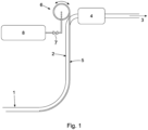
- Figure 1 illustrates a flowline 1 and a riser 2 which carry gas and liquids in a direction 3 towards a processing facility.
- a first stage separator 4 is used. The pressure at the first stage separator is 20 Bar(a).
- a coiled tubing 5 extends into the riser and is arranged to draw fluid from the lowest part of the riser 2.
- the coiled tubing 5 is provided on a reel 6 outside the riser. The reel 6 can be used to wind and unwind the coiled tubing, corresponding respectively to reducing and extending the amount of the coiled tubing extending into the riser 5.
- a valve 7 controls the flow of fluid from the coiled tubing towards a low pressure tank 8.
- low pressure tank 8 is kept at a pressure of around 2 Bar(a), while the pressure at first stage separator 4 is 20 Bar(a).
- the fluid is pumped from the low pressure tank to a further part of the process, such as a second stage separator (not illustrated).
- low pressure tank 8 can be a separator, such as a 2 nd stage, a 3 rd stage or higher stage separator.
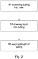
- Figure 2 illustrates a method disclosed herein.
- the method includes the steps of: S1, extending a portion of flexible tubing into the riser; S2, drawing liquid from the riser into the flexible tubing if liquid is present in the riser by creating a pressure differential within the flexible tubing with a pressure control system; and S3, varying the length of said portion of the flexible tubing depending on the amount of liquid drawn into the flexible tubing.
- the system described herein allows for reduction of the risk of a surge wave formation.
- the system can be used to extend the lifetime of gas-condensate fields. Without proper methods for surge mitigation, flowlines may need to be abandoned due to severe surge instabilities. Being able to efficiently remove liquid from the flowlines by way of the present system prevents surge instabilities partly or completely, thereby enabling continued production.
- FIG. 3 illustrates an arrangement similar to the arrangement of Fig. 1 , wherein the same reference numbers are used for the same features.
- the inset illustrates schematically a flow 31 within flowline 1 wherein the flow includes gas and a liquid condensate against the lower inner surface.
- a gas flow 32 will enter the riser and a mixture of gas and liquid 33 will flow upwards within flexible tubing.
- Line 35 illustrates the interface between the sea level and an air gap
- line 36 illustrates the interface between the airgap and the topside.
- a connection 37 is provided which connects the riser 2 to the topside piping.
- control unit 40 which may include low pressure tank 8 (in which case elements 8 and 40 in Fig. 3 would be combined) or a different pressure control device.
- This arrangement enables use of the coiled tubing system without routing the gas-liquid mixture lifted from the riser via the reel.
- the arrangement without the reel has fewer components and has a reduced risk of leaks when compared to a system with a reel, and is therefore more likely to be approved as a permanent part of a production system.
- the initial arrangement can then also be set up using a reel located on a ship.
- the flexible tubing When the flexible tubing has been inserted into the riser, the flexible tubing can be terminated topside and can be attached to the tubing, referred to as 'hanged off', and the ship can sail away with the reel.
- the length of the flexible tubing is fixed, the amount of liquid being drawn into the flexible tubing can be controlled by setting the pressure inside the flexible tubing.
- a choke valve to a higher stage separator can be used to set the pressure, or the speed of a multiphase pump can be used as a control parameter.
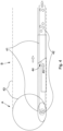
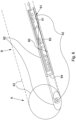
- FIG. 4 illustrates a specific embodiment of an intake device in more detail.
- the intake device 41 is attached to the end of the flexible tubing 42.
- the flexible tubing can be coiled tubing.
- Part A of Fig. 4 is a cross section in radial direction of the riser and part B is a cross section of the riser (or flowline) 43 in axial direction.
- the cross section of the intake device in radial direction shows an oval shape such that the area in which the intake device is in contact with the inside wall of the riser is larger than if the intake device had a circular cross section like the flexible tubing 42.
- Single phase gas flows through the riser and partially into the intake device as illustrated with arrows 44.
- a liquid film is drawn into the intake device as indicated by arrow 45.
- the flexible tubing will contain a mixture of gas and liquid.
- the intake device of the illustrated embodiment is urged against the lower inside wall of the riser by the weight of the intake device.
- a specific example of the weight of the intake device is 100 kg for a 40 cm internal diameter riser.
- the connection between the flexible tubing and the intake device may be a swivel connection to allow the assembly to move past bends, or alternatively the connection may be a fixed connection.
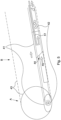
- Figure 5 illustrates a further embodiment.
- the same reference numbers as those in Fig. 4 correspond to the same components as described previously.
- the methods disclosed herein could also be used in deep water risers, or within a well, where the pressure differential between a high pressure tank, such as tank 4 in Fig. 3 , and a low pressure tank, such as tank 8 or device 40 in Fig. 3 , at the topside is not sufficient to lift a single phase liquid all the way from the sea bed to the topside within the flexible tubing.
- the suction as a result of the pressure differential may not be sufficiently strong to transport the liquid upwards over a long distance. If the suction is not sufficient, gas lift could be used to start the flow of liquid within the flexible tubing.
- FIG. 5 illustrates a gas nozzle 51 arranged within the flexible tubing and terminating within or near the intake device 41 such that gas flow can be provided to start the flow into the flexible tubing or to support continuous flow within the flexible tubing.
- the lift gas can be sent from the topside (or well head) using concentric coiled tubing (i.e. pipe-in-pipe) on a coil.
- concentric coiled tubing i.e. pipe-in-pipe
- parallel strings of regular coiled tubing bound together side by side can be used.
- FIG. 6 illustrates a further embodiment.
- the same reference numerals as in figures 4 and 5 correspond to the same components.
- the flow of liquids is now different from the flow illustrated in Figs 4 and 5 .
- the liquid 61 flows downwards within the pipe section above the intake device 62.
- the intake device is shaped such that the downwards flow is captured and channelled into the flexible tubing. Liquid accumulates above the inflow device as illustrated by shaded area 63 before being pumped upstream by the pressure differential.
- the end portion 64 of the intake device facing downwards is closed while the end portion 65 of the intake device facing upwards is open to receive the fluid.
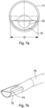
- Figure 7a illustrates a radial cross section through a riser 71 in which an intake device 72 and flexible tubing 73 are provided.
- Figure 7b illustrates a perspective view of the intake device and flexible tubing.
- intake device is biased against the inner wall of the riser by gravity.
- the lower part of the intake device has curvature which matches the curvature corresponding to inner diameter D of the riser.
- the lower part of the intake device is flush with the inner wall of the riser.
- a fluid film which is present at the lower part of the riser will be drawn into the intake device when the flexible tubing is at a lower pressure than the riser.
- the upper part 74 of the intake device is flat so as to reduce the amount of gas which is drawn into the flexible tubing.
- the upper part of the can also have other shapes than the flat shape illustrated in Figures 7a and 7b , for example a convex or concave shape.
Landscapes
- Engineering & Computer Science (AREA)
- Life Sciences & Earth Sciences (AREA)
- Geology (AREA)
- Mining & Mineral Resources (AREA)
- Physics & Mathematics (AREA)
- Environmental & Geological Engineering (AREA)
- Fluid Mechanics (AREA)
- General Life Sciences & Earth Sciences (AREA)
- Geochemistry & Mineralogy (AREA)
- Mechanical Engineering (AREA)
- Geophysics (AREA)
- Chemical & Material Sciences (AREA)
- General Chemical & Material Sciences (AREA)
- Oil, Petroleum & Natural Gas (AREA)
- Chemical Kinetics & Catalysis (AREA)
- Rigid Pipes And Flexible Pipes (AREA)
- Pipeline Systems (AREA)
- Pipe Accessories (AREA)
- Exchange Systems With Centralized Control (AREA)
- Earth Drilling (AREA)
Claims (15)
- System zum Schwallschutz einer Steigleitung (2), das zum Transportieren von Gas aus einem Kohlenwasserstoff-Produktionsbohrloch angepasst ist, oder zum Schwallschutz in einem Bohrloch, wobei das System Folgendes umfasst:einen flexiblen Schlauch (5), wobei sich ein Abschnitt des flexiblen Schlauchs in die Steigleitung (2) oder in das Bohrloch erstreckt und wobei der flexible Schlauch (5) innerhalb der Steigleitung (2) oder innerhalb des Bohrlochs endet, wobei das Ende des flexiblen Schlauchs (42) an einer Einlassvorrichtung (41) angebracht ist, wobei die Einlassvorrichtung (41) einen mindestens teilweise ovalen Querschnitt in einer radialen Richtung des flexiblen Schlauchs aufweist, oder wobei die Einlassvorrichtung (72) an einem Endabschnitt endet, wobei der Endabschnitt der Einlassvorrichtung eine teilweise rohrförmige Außenwand umfasst, wobei die äußere Krümmung der teilweise rohrförmigen Außenwand der inneren Krümmung der Innenwand der Steigleitung (2) oder des Bohrlochs entspricht;ein Drucksteuersystem, das so angeordnet ist, dass es eine Druckdifferenz innerhalb des flexiblen Schlauchs (5) erzeugt, sodass Flüssigkeit aus der Steigleitung (2) oder dem Bohrloch in den flexiblen Schlauch (5) gesaugt wird, wenn Flüssigkeit in der Steigleitung (2) oder dem Bohrloch vorhanden ist.
- System nach Anspruch 1,wobei der Schwall einen Flüssigkeitsfilm umfasst, der sich an einer Innenwand der Steigleitung (2) oder des Bohrlochs sammelt;wobei das Drucksteuersystem einen Druckübertragungskanal zwischen der Steigleitung (2) oder dem Bohrloch und einem Separator (4) der ersten Stufe, und einen Druckübertragungskanal zwischen dem flexiblen Schlauch (5) und einer Vorrichtung (8; 40) umfasst, welche einen niedrigeren Druck als der Separator (4) der ersten Stufe aufweist; undwobei im Gebrauch die teilweise rohrförmige Außenwand gegen die Innenwand der Steigleitung (2) oder des Bohrlochs gedrückt ist.
- System nach Anspruch 1 oder 2, ferner umfassend eine Spule (6) zum Speichern eines weiteren Abschnitts des flexiblen Schlauchs (5) und zum Variieren der Länge des Abschnitts des flexiblen Schlauchs (5), der sich in die Steigleitung (2) oder in das Bohrloch erstreckt.
- System nach einem der vorhergehenden Ansprüche, ferner umfassendeinen Drucksensor, der so angeordnet ist, dass er den Druck in dem flexiblen Schlauch misst,ein Steuersystem (40), das so angeordnet ist, dass es die Länge des Abschnitts vergrößert, wenn der Druck in dem flexiblen Schlauch (5) unter einem ersten Schwellenwert liegt, und so angeordnet ist, dass es die Länge des Abschnitts verkleinert, wenn der Druck in dem flexiblen Schlauch (5) über einem zweiten Schwellenwert liegt, und optional, wobei der erste Schwellenwert und der zweite Schwellenwert gleich sind, oder wobei der zweite Schwellenwert höher ist als der erste Schwellenwert.
- System nach einem der vorhergehenden Ansprüche, ferner umfassendeinen Detektor, der so angeordnet ist, dass er das Vorhandensein von Fluid oder die Menge an Fluid in dem flexiblen Schlauch (5) erfasst,ein Steuersystem (40), das zu Folgendem angeordnet ist:
Vergrößern der Länge des Abschnitts, wenn die Menge an erfasstem Fluid unter einem ersten Schwellenwert liegt, oder wenn kein Fluid erfasst wird; wobei das Steuersystem ferner zum Folgenden angeordnet ist:
Verkleinern der Länge des Abschnitts, wenn die Menge an erfasstem Fluid über einem Schwellenwert liegt. - System nach Anspruch 2, wobei die Vorrichtung (8; 40) mit einem niedrigeren Druck als der Separator (4) der ersten Stufe eines oder mehrere von Folgendem umfasst:ein Niederdrucktank und ein Ventil (7);ein Separator der zweiten oder einer höheren Stufe.
- System nach Anspruch 1, wobei das Drucksteuersystem eine erste Verbindung zwischen dem Bohrloch und einer ersten Strömungsleitung und eine zweite Verbindung zwischen dem flexiblen Schlauch und einer zweiten Strömungsleitung umfasst, und wobei der Druck in der ersten Strömungsleitung höher ist als der Druck in der zweiten Strömungsleitung.
- System nach einem der vorhergehenden Ansprüche, ferner umfassend ein Rückführungssystem zum Rückführen von durch den flexiblen Schlauch (5) entnommenem Fluid zurück in den Produktionsprozess, und wobei das Rückführungssystem optional eine Mehrphasenpumpe umfasst.
- System nach einem der vorhergehenden Ansprüche, ferner umfassend einen Abstandshalter oder ein Gewicht, der/das angeordnet ist, um das Ende des flexiblen Schlauchs (42) gegen eine Innenwand der Steigleitung (2) oder des Bohrlochs zu drücken.
- System nach einem der vorangehenden Ansprüche, ferner umfassend eine Gasströmungsleitung (43), die an oder in der Nähe der Stelle endet, an welcher der flexible Schlauch (5) endet, wobei die Gasströmungsleitung (43) geeignet ist, um Gas in den flexiblen Schlauch (5) einzublasen, um einen Gasauftrieb bereitzustellen.
- Verfahren zum Schützen einer Steigleitung (2), die zum Transportieren von Gas aus einem Kohlenwasserstoff-Produktionsbohrloch angepasst ist, gegen Druckschwalle oder zum Schutz eines Bohrlochs gegen Druckschwalle, wobei das Verfahren Folgendes umfasst:
Verlängern (S1) eines Abschnitts eines flexiblen Schlauchs in die Steigleitung (2) oder in das Bohrloch, wobei der flexible Schlauch (5) innerhalb der Steigleitung (2) oder des Bohrlochs endet, wobei das Ende des flexiblen Schlauchs (42) an einer Einlassvorrichtung angebracht ist, wobei die Einlassvorrichtung (41) einen mindestens teilweise ovalen Querschnitt in radialer Richtung des flexiblen Schlauches aufweist, oder wobei die Einlassvorrichtung (41) an einem Endabschnitt endet, wobei der Endabschnitt der Einlassvorrichtung eine teilweise rohrförmige Außenwand umfasst, wobei die äußere Krümmung der teilweise rohrförmigen Außenwand der inneren Krümmung der Innenwand der Steigleitung (2) oder des Bohrlochs entspricht;
Saugen (S2) von Flüssigkeit aus der Steigleitung (2) oder dem Bohrloch in den flexiblen Schlauch (5), wenn Flüssigkeit in der Steigleitung (2) oder in dem Bohrloch vorhanden ist, indem mit einem Drucksteuersystem eine Druckdifferenz innerhalb des flexiblen Schlauchs (5) erzeugt wird. - Verfahren nach Anspruch 11,wobei der Schwall einen Flüssigkeitsfilm umfasst, der sich an einer Innenwand der Steigleitung (2) oder des Bohrlochs ansammelt;wobei das Erzeugen der Druckdifferenz das Bereitstellen eines Druckübertragungskanals zwischen der Steigleitung (2) oder dem Bohrloch und einem Separator (4) der ersten Stufe, und das Bereitstellen eines Druckübertragungskanals zwischen dem flexiblen Schlauch (5) und einer Vorrichtung (8; 40) mit einem niedrigeren Druck als in dem Separator (4) der ersten Stufe umfasst; undwobei das Verfahren ferner das Vorspannen der teilweise rohrförmigen Außenwand des Endabschnitts gegen die Innenwand der Steigleitung (2) oder des Bohrlochs umfasst.
- Verfahren nach Anspruch 11 oder 12, wobei das Verfahren ferner das Verändern (S3) der Länge des Abschnitts des flexiblen Schlauchs (5) durch Auf- oder Abrollen des flexiblen Schlauchs (5) auf einer Spule (6), oder das Anpassen des Drucks innerhalb des flexiblen Schlauchs (5) umfasst, als Reaktion aufdas Bestimmen des Drucks innerhalb des flexiblen Schlauchs (5), oderdas Bestimmen der Flüssigkeitsmenge innerhalb des flexiblen Schlauchs (5) und das Verändern der Länge in Abhängigkeit von dem Bestimmen; und optional gefolgt von einem Schritt desSchneidens des flexiblen Schlauchs (5), des Anhängens des flexiblen Schlauchs (5) an die Steigleitung (2), und des Verbindens des flexiblen Schlauchs (5) mit dem Drucksteuersystem.
- Verfahren nach Anspruch 11, wobei das Ansaugen von Flüssigkeit Folgendes umfasst:Regeln eines Ventils (7) zu einem Niederdrucktank oder zu einem Separator (8; 40), oderSteuern einer Pumpe.
- Verfahren nach einem der Ansprüche 11 bis 14, ferner umfassend das Bereitstellen einer Gasströmungsleitung (43) und das Einblasen von Gas in den flexiblen Schlauch (5).
Applications Claiming Priority (3)
| Application Number | Priority Date | Filing Date | Title |
|---|---|---|---|
| GB1716719.8A GB2567458A (en) | 2017-10-12 | 2017-10-12 | Riser surge protection system |
| GB1811556.8A GB2567514B (en) | 2017-10-12 | 2018-07-13 | Riser surge protection system |
| PCT/NO2018/050244 WO2019074376A1 (en) | 2017-10-12 | 2018-10-12 | UPLINK OVERVOLTAGE PROTECTION SYSTEM |
Publications (3)
| Publication Number | Publication Date |
|---|---|
| EP3695094A1 EP3695094A1 (de) | 2020-08-19 |
| EP3695094A4 EP3695094A4 (de) | 2021-06-23 |
| EP3695094B1 true EP3695094B1 (de) | 2023-12-06 |
Family
ID=60419331
Family Applications (2)
| Application Number | Title | Priority Date | Filing Date |
|---|---|---|---|
| EP18866350.4A Active EP3695096B1 (de) | 2017-10-12 | 2018-10-12 | Inline-phasentrennung |
| EP18865782.9A Active EP3695094B1 (de) | 2017-10-12 | 2018-10-12 | Überspannungsschutzsystem einer steigleitung |
Family Applications Before (1)
| Application Number | Title | Priority Date | Filing Date |
|---|---|---|---|
| EP18866350.4A Active EP3695096B1 (de) | 2017-10-12 | 2018-10-12 | Inline-phasentrennung |
Country Status (6)
| Country | Link |
|---|---|
| US (2) | US11391140B2 (de) |
| EP (2) | EP3695096B1 (de) |
| AU (2) | AU2018348582B2 (de) |
| GB (2) | GB2567458A (de) |
| MX (1) | MX2020003634A (de) |
| WO (2) | WO2019074376A1 (de) |
Families Citing this family (6)
| Publication number | Priority date | Publication date | Assignee | Title |
|---|---|---|---|---|
| US11773653B2 (en) * | 2019-12-23 | 2023-10-03 | Southwest Petroleum University | Double-layer coiled tubing double-gradient drilling system |
| GB2582431B (en) * | 2020-01-21 | 2021-11-17 | Equinor Energy As | Riser surge protection system |
| WO2022170414A1 (en) | 2021-02-12 | 2022-08-18 | Drill Safe Systems Inc. | Drilling downhole regulating devices and related methods |
| US12292059B2 (en) | 2022-03-08 | 2025-05-06 | Inflow Systems Inc. | Intakes and gas separators for downhole pumps, and related apparatuses and methods |
| CN115671800A (zh) * | 2022-11-10 | 2023-02-03 | 芜湖润利化工有限公司 | 一种二甲苯生产恒压分离装置 |
| GB2627735B (en) * | 2023-02-24 | 2025-09-17 | Paradigm Flow Services Ltd | Apparatus, system and method for use in artificial lift operations |
Family Cites Families (26)
| Publication number | Priority date | Publication date | Assignee | Title |
|---|---|---|---|---|
| CA1325969C (en) * | 1987-10-28 | 1994-01-11 | Tad A. Sudol | Conduit or well cleaning and pumping device and method of use thereof |
| US4926937A (en) * | 1989-06-08 | 1990-05-22 | Western Atlas International, Inc. | Compound linkage-arm assembly for use in bore-hole tools |
| US5080560A (en) * | 1990-02-20 | 1992-01-14 | Leroy Jack W | Dryrite borehole dewatering system |
| US5138585A (en) * | 1990-04-27 | 1992-08-11 | Chevron Research & Technology Company | Method for fluid identification and evaluation within wellbores using ultrasonic scanning |
| CA2120283C (en) * | 1994-03-30 | 2004-05-18 | Bernard Heinrichs | Down-hole gas separator |
| US5632335A (en) * | 1995-10-10 | 1997-05-27 | Campbell; Wallace R. | Well tubing and pump rod protector |
| FR2741382B1 (fr) * | 1995-11-21 | 1997-12-26 | Inst Francais Du Petrole | Methode et dispositif de production par pompage dans un drain horizontal |
| CA2193923C (en) * | 1996-12-24 | 2007-01-23 | Tadeus Sudol | Method of oil/gas stimulation |
| NO321386B1 (no) * | 1997-03-19 | 2006-05-02 | Norsk Hydro As | Fremgangsmate og anordning for separering av et fluid omfattende flere fluidkomponenter, fortrinnsvis separering av et bronnfluid i forbindelse med et ror for produksjon av hydrokarboner/vann |
| GB2326895B (en) | 1997-07-03 | 1999-08-18 | Schlumberger Ltd | Seperation of oil-well fluid mixtures |
| US5904209A (en) | 1998-10-26 | 1999-05-18 | Technology Commercialization Corp. | Method and device for removal of production inhibiting liquid from a gas well |
| US6716268B2 (en) | 2000-01-17 | 2004-04-06 | Lattice Intellectual Property Ltd. | Slugging control |
| NO311814B1 (no) | 2000-02-23 | 2002-01-28 | Abb Research Ltd | Anordning og fremgangsmate for utvinning av olje |
| US7080686B2 (en) * | 2002-11-13 | 2006-07-25 | David Beckhardt | Devices and methods for extraction, transportation and/or release of material |
| US7314089B2 (en) * | 2003-08-26 | 2008-01-01 | Weatherford/Lamb, Inc. | Method of wellbore pumping apparatus with improved temperature performance and method of use |
| MY137403A (en) | 2004-12-21 | 2009-01-30 | Shell Int Research | Method, system, controller and computer program product for controlling the flow of a multiphase fluid |
| US8636478B2 (en) | 2006-01-11 | 2014-01-28 | Besst, Inc. | Sensor assembly for determining fluid properties in a subsurface well |
| CA2687058C (en) | 2007-05-16 | 2016-01-26 | Statoil Asa | Method for liquid control in multiphase fluid pipelines |
| US20120067569A1 (en) | 2010-09-22 | 2012-03-22 | Alan Keith Brown | Well De-Liquefying System and Method |
| US8794305B2 (en) * | 2011-10-24 | 2014-08-05 | Scott J Wilson | Method and apparatus for removing liquid from a horizontal well |
| US8967271B2 (en) * | 2012-06-07 | 2015-03-03 | Kellogg Brown & Root Llc | Subsea overpressure relief device |
| NO338020B1 (no) | 2013-09-10 | 2016-07-18 | Mhwirth As | Et dypvanns borestigerørstrykkavlastningssystem omfattende en trykkfrigjøringsanordning, samt bruk av trykkfrigjøringsanordningen. |
| US9494022B2 (en) * | 2014-01-23 | 2016-11-15 | Baker Hughes Incorporated | Gas restrictor for a horizontally oriented submersible well pump |
| WO2016057126A1 (en) * | 2014-10-10 | 2016-04-14 | Exxonmobil Upstream Research Company | Bubble pump utilization for vertical flow line liquid unloading |
| US10934792B2 (en) * | 2015-02-13 | 2021-03-02 | Schlumberger Technology Corporation | Powered sheave with wireline pushing capability |
| US10260330B2 (en) * | 2015-04-29 | 2019-04-16 | General Electric Company | Fluid intake for an artificial lift system and method of operating such system |
-
2017
- 2017-10-12 GB GB1716719.8A patent/GB2567458A/en not_active Withdrawn
-
2018
- 2018-07-13 GB GB1811556.8A patent/GB2567514B/en active Active
- 2018-10-12 US US16/755,469 patent/US11391140B2/en active Active
- 2018-10-12 MX MX2020003634A patent/MX2020003634A/es unknown
- 2018-10-12 AU AU2018348582A patent/AU2018348582B2/en active Active
- 2018-10-12 AU AU2018348581A patent/AU2018348581B2/en active Active
- 2018-10-12 EP EP18866350.4A patent/EP3695096B1/de active Active
- 2018-10-12 WO PCT/NO2018/050244 patent/WO2019074376A1/en not_active Ceased
- 2018-10-12 WO PCT/NO2018/050245 patent/WO2019074377A1/en not_active Ceased
- 2018-10-12 EP EP18865782.9A patent/EP3695094B1/de active Active
- 2018-10-12 US US16/755,459 patent/US11629586B2/en active Active
Also Published As
| Publication number | Publication date |
|---|---|
| GB201716719D0 (en) | 2017-11-29 |
| EP3695096A4 (de) | 2021-08-11 |
| CA3078694A1 (en) | 2019-04-18 |
| AU2018348582A1 (en) | 2020-04-30 |
| WO2019074377A1 (en) | 2019-04-18 |
| MX2020003634A (es) | 2020-07-29 |
| AU2018348581B2 (en) | 2023-11-30 |
| CA3078693A1 (en) | 2019-04-18 |
| AU2018348581A1 (en) | 2020-05-07 |
| WO2019074376A1 (en) | 2019-04-18 |
| US11629586B2 (en) | 2023-04-18 |
| GB2567514A (en) | 2019-04-17 |
| BR112020006819A2 (pt) | 2020-10-06 |
| AU2018348582B2 (en) | 2024-06-13 |
| US20210222527A1 (en) | 2021-07-22 |
| US11391140B2 (en) | 2022-07-19 |
| GB2567514B (en) | 2021-01-20 |
| BR112020006824A2 (pt) | 2020-10-06 |
| GB2567458A (en) | 2019-04-17 |
| EP3695094A4 (de) | 2021-06-23 |
| EP3695096B1 (de) | 2023-03-15 |
| US20200332641A1 (en) | 2020-10-22 |
| EP3695094A1 (de) | 2020-08-19 |
| EP3695096A1 (de) | 2020-08-19 |
| GB201811556D0 (en) | 2018-08-29 |
Similar Documents
| Publication | Publication Date | Title |
|---|---|---|
| US11391140B2 (en) | Riser surge protection system | |
| US8342248B2 (en) | Apparatus for venting an annular space between a liner and a pipeline of a subsea riser | |
| US7210530B2 (en) | Subsea separation system | |
| US20070175641A1 (en) | Method and apparatus for lifting liquids from gas wells | |
| US9869164B2 (en) | Inclined wellbore optimization for artificial lift applications | |
| EP3529458B1 (de) | Verfahren und vorrichtung zur stabilisierung von eines gas-/flüssigkeitsstroms in einer vertikalen leitung | |
| US20240125223A1 (en) | Sand collector for sucker rod pump | |
| US20050205261A1 (en) | System and method for remediating pipeline blockage | |
| CA3078693C (en) | Riser surge protection system | |
| CA3078694C (en) | In-line phase separation | |
| BR112020006824B1 (pt) | Sistema de proteção contra compressão de tubo ascendente e método para proteger um tubo ascendente | |
| US20230101329A1 (en) | Riser surge protection system | |
| GB2422159A (en) | Venturi removal of water in a gas wall | |
| BR112020006819B1 (pt) | Método e sistema para separação de fases fluidas em um poço ou tubo ascendente | |
| GB2580195A (en) | Apparatus for liquid transport in a hydrocarbon well | |
| RU2792861C1 (ru) | Способ эксплуатации скважин | |
| RU2000117228A (ru) | Способ освоения нефтяных и газовых скважин и устройство для его осуществления |
Legal Events
| Date | Code | Title | Description |
|---|---|---|---|
| STAA | Information on the status of an ep patent application or granted ep patent |
Free format text: STATUS: THE INTERNATIONAL PUBLICATION HAS BEEN MADE |
|
| PUAI | Public reference made under article 153(3) epc to a published international application that has entered the european phase |
Free format text: ORIGINAL CODE: 0009012 |
|
| STAA | Information on the status of an ep patent application or granted ep patent |
Free format text: STATUS: REQUEST FOR EXAMINATION WAS MADE |
|
| 17P | Request for examination filed |
Effective date: 20200323 |
|
| AK | Designated contracting states |
Kind code of ref document: A1 Designated state(s): AL AT BE BG CH CY CZ DE DK EE ES FI FR GB GR HR HU IE IS IT LI LT LU LV MC MK MT NL NO PL PT RO RS SE SI SK SM TR |
|
| AX | Request for extension of the european patent |
Extension state: BA ME |
|
| DAV | Request for validation of the european patent (deleted) | ||
| DAX | Request for extension of the european patent (deleted) | ||
| A4 | Supplementary search report drawn up and despatched |
Effective date: 20210526 |
|
| RIC1 | Information provided on ipc code assigned before grant |
Ipc: E21B 43/013 20060101AFI20210519BHEP Ipc: E21B 21/08 20060101ALI20210519BHEP Ipc: E21B 43/01 20060101ALI20210519BHEP Ipc: F16L 1/12 20060101ALI20210519BHEP Ipc: F16L 1/15 20060101ALI20210519BHEP Ipc: F16L 3/00 20060101ALI20210519BHEP Ipc: F16L 5/00 20060101ALI20210519BHEP Ipc: B01D 19/00 20060101ALI20210519BHEP Ipc: E21B 43/12 20060101ALI20210519BHEP |
|
| STAA | Information on the status of an ep patent application or granted ep patent |
Free format text: STATUS: EXAMINATION IS IN PROGRESS |
|
| 17Q | First examination report despatched |
Effective date: 20220808 |
|
| GRAP | Despatch of communication of intention to grant a patent |
Free format text: ORIGINAL CODE: EPIDOSNIGR1 |
|
| STAA | Information on the status of an ep patent application or granted ep patent |
Free format text: STATUS: GRANT OF PATENT IS INTENDED |
|
| INTG | Intention to grant announced |
Effective date: 20230516 |
|
| RIN1 | Information on inventor provided before grant (corrected) |
Inventor name: VALLE, ARNE Inventor name: EIDSMOEN, HAVARD Inventor name: KJELDBY, TOR KINDSBEKKEN Inventor name: NORDSVEEN, MAGNUS |
|
| GRAS | Grant fee paid |
Free format text: ORIGINAL CODE: EPIDOSNIGR3 |
|
| GRAA | (expected) grant |
Free format text: ORIGINAL CODE: 0009210 |
|
| STAA | Information on the status of an ep patent application or granted ep patent |
Free format text: STATUS: THE PATENT HAS BEEN GRANTED |
|
| AK | Designated contracting states |
Kind code of ref document: B1 Designated state(s): AL AT BE BG CH CY CZ DE DK EE ES FI FR GB GR HR HU IE IS IT LI LT LU LV MC MK MT NL NO PL PT RO RS SE SI SK SM TR |
|
| REG | Reference to a national code |
Ref country code: GB Ref legal event code: FG4D |
|
| REG | Reference to a national code |
Ref country code: CH Ref legal event code: EP |
|
| REG | Reference to a national code |
Ref country code: DE Ref legal event code: R096 Ref document number: 602018062376 Country of ref document: DE |
|
| REG | Reference to a national code |
Ref country code: IE Ref legal event code: FG4D |
|
| REG | Reference to a national code |
Ref country code: NO Ref legal event code: T2 Effective date: 20231206 |
|
| REG | Reference to a national code |
Ref country code: LT Ref legal event code: MG9D |
|
| PG25 | Lapsed in a contracting state [announced via postgrant information from national office to epo] |
Ref country code: GR Free format text: LAPSE BECAUSE OF FAILURE TO SUBMIT A TRANSLATION OF THE DESCRIPTION OR TO PAY THE FEE WITHIN THE PRESCRIBED TIME-LIMIT Effective date: 20240307 |
|
| REG | Reference to a national code |
Ref country code: NL Ref legal event code: MP Effective date: 20231206 |
|
| PG25 | Lapsed in a contracting state [announced via postgrant information from national office to epo] |
Ref country code: LT Free format text: LAPSE BECAUSE OF FAILURE TO SUBMIT A TRANSLATION OF THE DESCRIPTION OR TO PAY THE FEE WITHIN THE PRESCRIBED TIME-LIMIT Effective date: 20231206 |
|
| PG25 | Lapsed in a contracting state [announced via postgrant information from national office to epo] |
Ref country code: ES Free format text: LAPSE BECAUSE OF FAILURE TO SUBMIT A TRANSLATION OF THE DESCRIPTION OR TO PAY THE FEE WITHIN THE PRESCRIBED TIME-LIMIT Effective date: 20231206 |
|
| PG25 | Lapsed in a contracting state [announced via postgrant information from national office to epo] |
Ref country code: LT Free format text: LAPSE BECAUSE OF FAILURE TO SUBMIT A TRANSLATION OF THE DESCRIPTION OR TO PAY THE FEE WITHIN THE PRESCRIBED TIME-LIMIT Effective date: 20231206 Ref country code: GR Free format text: LAPSE BECAUSE OF FAILURE TO SUBMIT A TRANSLATION OF THE DESCRIPTION OR TO PAY THE FEE WITHIN THE PRESCRIBED TIME-LIMIT Effective date: 20240307 Ref country code: ES Free format text: LAPSE BECAUSE OF FAILURE TO SUBMIT A TRANSLATION OF THE DESCRIPTION OR TO PAY THE FEE WITHIN THE PRESCRIBED TIME-LIMIT Effective date: 20231206 Ref country code: BG Free format text: LAPSE BECAUSE OF FAILURE TO SUBMIT A TRANSLATION OF THE DESCRIPTION OR TO PAY THE FEE WITHIN THE PRESCRIBED TIME-LIMIT Effective date: 20240306 |
|
| REG | Reference to a national code |
Ref country code: AT Ref legal event code: MK05 Ref document number: 1638582 Country of ref document: AT Kind code of ref document: T Effective date: 20231206 |
|
| PG25 | Lapsed in a contracting state [announced via postgrant information from national office to epo] |
Ref country code: NL Free format text: LAPSE BECAUSE OF FAILURE TO SUBMIT A TRANSLATION OF THE DESCRIPTION OR TO PAY THE FEE WITHIN THE PRESCRIBED TIME-LIMIT Effective date: 20231206 |
|
| PG25 | Lapsed in a contracting state [announced via postgrant information from national office to epo] |
Ref country code: SE Free format text: LAPSE BECAUSE OF FAILURE TO SUBMIT A TRANSLATION OF THE DESCRIPTION OR TO PAY THE FEE WITHIN THE PRESCRIBED TIME-LIMIT Effective date: 20231206 Ref country code: RS Free format text: LAPSE BECAUSE OF FAILURE TO SUBMIT A TRANSLATION OF THE DESCRIPTION OR TO PAY THE FEE WITHIN THE PRESCRIBED TIME-LIMIT Effective date: 20231206 Ref country code: NL Free format text: LAPSE BECAUSE OF FAILURE TO SUBMIT A TRANSLATION OF THE DESCRIPTION OR TO PAY THE FEE WITHIN THE PRESCRIBED TIME-LIMIT Effective date: 20231206 Ref country code: LV Free format text: LAPSE BECAUSE OF FAILURE TO SUBMIT A TRANSLATION OF THE DESCRIPTION OR TO PAY THE FEE WITHIN THE PRESCRIBED TIME-LIMIT Effective date: 20231206 Ref country code: HR Free format text: LAPSE BECAUSE OF FAILURE TO SUBMIT A TRANSLATION OF THE DESCRIPTION OR TO PAY THE FEE WITHIN THE PRESCRIBED TIME-LIMIT Effective date: 20231206 |
|
| PG25 | Lapsed in a contracting state [announced via postgrant information from national office to epo] |
Ref country code: IS Free format text: LAPSE BECAUSE OF FAILURE TO SUBMIT A TRANSLATION OF THE DESCRIPTION OR TO PAY THE FEE WITHIN THE PRESCRIBED TIME-LIMIT Effective date: 20240406 |
|
| PG25 | Lapsed in a contracting state [announced via postgrant information from national office to epo] |
Ref country code: AT Free format text: LAPSE BECAUSE OF FAILURE TO SUBMIT A TRANSLATION OF THE DESCRIPTION OR TO PAY THE FEE WITHIN THE PRESCRIBED TIME-LIMIT Effective date: 20231206 Ref country code: CZ Free format text: LAPSE BECAUSE OF FAILURE TO SUBMIT A TRANSLATION OF THE DESCRIPTION OR TO PAY THE FEE WITHIN THE PRESCRIBED TIME-LIMIT Effective date: 20231206 |
|
| PG25 | Lapsed in a contracting state [announced via postgrant information from national office to epo] |
Ref country code: SK Free format text: LAPSE BECAUSE OF FAILURE TO SUBMIT A TRANSLATION OF THE DESCRIPTION OR TO PAY THE FEE WITHIN THE PRESCRIBED TIME-LIMIT Effective date: 20231206 |
|
| PG25 | Lapsed in a contracting state [announced via postgrant information from national office to epo] |
Ref country code: SM Free format text: LAPSE BECAUSE OF FAILURE TO SUBMIT A TRANSLATION OF THE DESCRIPTION OR TO PAY THE FEE WITHIN THE PRESCRIBED TIME-LIMIT Effective date: 20231206 Ref country code: SK Free format text: LAPSE BECAUSE OF FAILURE TO SUBMIT A TRANSLATION OF THE DESCRIPTION OR TO PAY THE FEE WITHIN THE PRESCRIBED TIME-LIMIT Effective date: 20231206 Ref country code: RO Free format text: LAPSE BECAUSE OF FAILURE TO SUBMIT A TRANSLATION OF THE DESCRIPTION OR TO PAY THE FEE WITHIN THE PRESCRIBED TIME-LIMIT Effective date: 20231206 Ref country code: IT Free format text: LAPSE BECAUSE OF FAILURE TO SUBMIT A TRANSLATION OF THE DESCRIPTION OR TO PAY THE FEE WITHIN THE PRESCRIBED TIME-LIMIT Effective date: 20231206 Ref country code: IS Free format text: LAPSE BECAUSE OF FAILURE TO SUBMIT A TRANSLATION OF THE DESCRIPTION OR TO PAY THE FEE WITHIN THE PRESCRIBED TIME-LIMIT Effective date: 20240406 Ref country code: EE Free format text: LAPSE BECAUSE OF FAILURE TO SUBMIT A TRANSLATION OF THE DESCRIPTION OR TO PAY THE FEE WITHIN THE PRESCRIBED TIME-LIMIT Effective date: 20231206 Ref country code: CZ Free format text: LAPSE BECAUSE OF FAILURE TO SUBMIT A TRANSLATION OF THE DESCRIPTION OR TO PAY THE FEE WITHIN THE PRESCRIBED TIME-LIMIT Effective date: 20231206 Ref country code: AT Free format text: LAPSE BECAUSE OF FAILURE TO SUBMIT A TRANSLATION OF THE DESCRIPTION OR TO PAY THE FEE WITHIN THE PRESCRIBED TIME-LIMIT Effective date: 20231206 |
|
| PG25 | Lapsed in a contracting state [announced via postgrant information from national office to epo] |
Ref country code: PL Free format text: LAPSE BECAUSE OF FAILURE TO SUBMIT A TRANSLATION OF THE DESCRIPTION OR TO PAY THE FEE WITHIN THE PRESCRIBED TIME-LIMIT Effective date: 20231206 Ref country code: PT Free format text: LAPSE BECAUSE OF FAILURE TO SUBMIT A TRANSLATION OF THE DESCRIPTION OR TO PAY THE FEE WITHIN THE PRESCRIBED TIME-LIMIT Effective date: 20240408 |
|
| PG25 | Lapsed in a contracting state [announced via postgrant information from national office to epo] |
Ref country code: PT Free format text: LAPSE BECAUSE OF FAILURE TO SUBMIT A TRANSLATION OF THE DESCRIPTION OR TO PAY THE FEE WITHIN THE PRESCRIBED TIME-LIMIT Effective date: 20240408 Ref country code: PL Free format text: LAPSE BECAUSE OF FAILURE TO SUBMIT A TRANSLATION OF THE DESCRIPTION OR TO PAY THE FEE WITHIN THE PRESCRIBED TIME-LIMIT Effective date: 20231206 |
|
| REG | Reference to a national code |
Ref country code: DE Ref legal event code: R097 Ref document number: 602018062376 Country of ref document: DE |
|
| PG25 | Lapsed in a contracting state [announced via postgrant information from national office to epo] |
Ref country code: DK Free format text: LAPSE BECAUSE OF FAILURE TO SUBMIT A TRANSLATION OF THE DESCRIPTION OR TO PAY THE FEE WITHIN THE PRESCRIBED TIME-LIMIT Effective date: 20231206 |
|
| PLBE | No opposition filed within time limit |
Free format text: ORIGINAL CODE: 0009261 |
|
| STAA | Information on the status of an ep patent application or granted ep patent |
Free format text: STATUS: NO OPPOSITION FILED WITHIN TIME LIMIT |
|
| PG25 | Lapsed in a contracting state [announced via postgrant information from national office to epo] |
Ref country code: SI Free format text: LAPSE BECAUSE OF FAILURE TO SUBMIT A TRANSLATION OF THE DESCRIPTION OR TO PAY THE FEE WITHIN THE PRESCRIBED TIME-LIMIT Effective date: 20231206 |
|
| PG25 | Lapsed in a contracting state [announced via postgrant information from national office to epo] |
Ref country code: SI Free format text: LAPSE BECAUSE OF FAILURE TO SUBMIT A TRANSLATION OF THE DESCRIPTION OR TO PAY THE FEE WITHIN THE PRESCRIBED TIME-LIMIT Effective date: 20231206 Ref country code: DK Free format text: LAPSE BECAUSE OF FAILURE TO SUBMIT A TRANSLATION OF THE DESCRIPTION OR TO PAY THE FEE WITHIN THE PRESCRIBED TIME-LIMIT Effective date: 20231206 |
|
| 26N | No opposition filed |
Effective date: 20240909 |
|
| REG | Reference to a national code |
Ref country code: DE Ref legal event code: R119 Ref document number: 602018062376 Country of ref document: DE |
|
| REG | Reference to a national code |
Ref country code: CH Ref legal event code: PL |
|
| PG25 | Lapsed in a contracting state [announced via postgrant information from national office to epo] |
Ref country code: MC Free format text: LAPSE BECAUSE OF FAILURE TO SUBMIT A TRANSLATION OF THE DESCRIPTION OR TO PAY THE FEE WITHIN THE PRESCRIBED TIME-LIMIT Effective date: 20231206 |
|
| PG25 | Lapsed in a contracting state [announced via postgrant information from national office to epo] |
Ref country code: DE Free format text: LAPSE BECAUSE OF NON-PAYMENT OF DUE FEES Effective date: 20250501 |
|
| PG25 | Lapsed in a contracting state [announced via postgrant information from national office to epo] |
Ref country code: BE Free format text: LAPSE BECAUSE OF NON-PAYMENT OF DUE FEES Effective date: 20241031 Ref country code: LU Free format text: LAPSE BECAUSE OF NON-PAYMENT OF DUE FEES Effective date: 20241012 |
|
| PG25 | Lapsed in a contracting state [announced via postgrant information from national office to epo] |
Ref country code: FR Free format text: LAPSE BECAUSE OF NON-PAYMENT OF DUE FEES Effective date: 20241031 |
|
| PG25 | Lapsed in a contracting state [announced via postgrant information from national office to epo] |
Ref country code: CH Free format text: LAPSE BECAUSE OF NON-PAYMENT OF DUE FEES Effective date: 20241031 |
|
| REG | Reference to a national code |
Ref country code: BE Ref legal event code: MM Effective date: 20241031 |
|
| PG25 | Lapsed in a contracting state [announced via postgrant information from national office to epo] |
Ref country code: FI Free format text: LAPSE BECAUSE OF FAILURE TO SUBMIT A TRANSLATION OF THE DESCRIPTION OR TO PAY THE FEE WITHIN THE PRESCRIBED TIME-LIMIT Effective date: 20231207 |
|
| PGFP | Annual fee paid to national office [announced via postgrant information from national office to epo] |
Ref country code: GB Payment date: 20251023 Year of fee payment: 8 |
|
| PGFP | Annual fee paid to national office [announced via postgrant information from national office to epo] |
Ref country code: NO Payment date: 20251022 Year of fee payment: 8 |
|
| PGFP | Annual fee paid to national office [announced via postgrant information from national office to epo] |
Ref country code: IE Payment date: 20251020 Year of fee payment: 8 |
|
| PG25 | Lapsed in a contracting state [announced via postgrant information from national office to epo] |
Ref country code: CY Free format text: LAPSE BECAUSE OF FAILURE TO SUBMIT A TRANSLATION OF THE DESCRIPTION OR TO PAY THE FEE WITHIN THE PRESCRIBED TIME-LIMIT; INVALID AB INITIO Effective date: 20181012 |
|
| PG25 | Lapsed in a contracting state [announced via postgrant information from national office to epo] |
Ref country code: HU Free format text: LAPSE BECAUSE OF FAILURE TO SUBMIT A TRANSLATION OF THE DESCRIPTION OR TO PAY THE FEE WITHIN THE PRESCRIBED TIME-LIMIT; INVALID AB INITIO Effective date: 20181012 |