EP3694751B1 - Buckle system - Google Patents
Buckle system Download PDFInfo
- Publication number
- EP3694751B1 EP3694751B1 EP18786256.0A EP18786256A EP3694751B1 EP 3694751 B1 EP3694751 B1 EP 3694751B1 EP 18786256 A EP18786256 A EP 18786256A EP 3694751 B1 EP3694751 B1 EP 3694751B1
- Authority
- EP
- European Patent Office
- Prior art keywords
- buckle
- tongue
- rfid transponder
- rfid
- lock
- Prior art date
- Legal status (The legal status is an assumption and is not a legal conclusion. Google has not performed a legal analysis and makes no representation as to the accuracy of the status listed.)
- Active
Links
- 230000008878 coupling Effects 0.000 claims description 16
- 238000010168 coupling process Methods 0.000 claims description 16
- 238000005859 coupling reaction Methods 0.000 claims description 16
- 229920003023 plastic Polymers 0.000 claims description 14
- 239000004033 plastic Substances 0.000 claims description 14
- 239000002184 metal Substances 0.000 claims description 9
- 238000005538 encapsulation Methods 0.000 claims description 7
- 230000005855 radiation Effects 0.000 claims description 6
- 230000005540 biological transmission Effects 0.000 claims description 4
- 239000000463 material Substances 0.000 claims description 4
- 210000002105 tongue Anatomy 0.000 description 48
- 238000004891 communication Methods 0.000 description 3
- 238000011161 development Methods 0.000 description 2
- 230000018109 developmental process Effects 0.000 description 2
- 238000005516 engineering process Methods 0.000 description 2
- BASFCYQUMIYNBI-UHFFFAOYSA-N platinum Chemical compound [Pt] BASFCYQUMIYNBI-UHFFFAOYSA-N 0.000 description 2
- 230000004913 activation Effects 0.000 description 1
- 230000001419 dependent effect Effects 0.000 description 1
- 238000013461 design Methods 0.000 description 1
- 230000005672 electromagnetic field Effects 0.000 description 1
- 238000007765 extrusion coating Methods 0.000 description 1
- 238000003780 insertion Methods 0.000 description 1
- 230000037431 insertion Effects 0.000 description 1
- 238000004519 manufacturing process Methods 0.000 description 1
- 230000000007 visual effect Effects 0.000 description 1
Images


Classifications
-
- B—PERFORMING OPERATIONS; TRANSPORTING
- B60—VEHICLES IN GENERAL
- B60R—VEHICLES, VEHICLE FITTINGS, OR VEHICLE PARTS, NOT OTHERWISE PROVIDED FOR
- B60R22/00—Safety belts or body harnesses in vehicles
- B60R22/48—Control systems, alarms, or interlock systems, for the correct application of the belt or harness
- B60R2022/4808—Sensing means arrangements therefor
- B60R2022/4816—Sensing means arrangements therefor for sensing locking of buckle
Definitions
- the invention relates to a seatbelt lock system which comprises a seatbelt lock and a lap tongue which can be inserted into the seatbelt lock.
- a switch is arranged in the seat belt lock, with which the insertion of a lock tongue into the seat belt lock can be detected. Because of this switch, it is possible for the driver to receive a visual and / or acoustic warning if he is not buckled up. It has been shown that some drivers insert a fake tongue or the front passenger's tongue into the seat belt buckle to avoid the warning. Such behavior is very dangerous. In addition, the signal from the seat belt buckle switch is often used to prove that a person is present in the driver's seat, as a result of which certain functions of the vehicle can be activated. There is therefore a need for a warning to be able to be output even if a lock tongue that is not assigned to the seat belt lock is inserted into the seat belt lock.
- the end DE 10 2006 055 141 A1 a seat belt buckle system with a switch in the seat belt buckle is known.
- the seatbelt lock switch is connected to an HF identification tag, the emittable identification signal of which is changed based on the switching state of the seatbelt lock switch, so that the status of the seatbelt lock can be transmitted wirelessly to the vehicle control via the HF identification tag.
- the use of such an HF identification tag in combination with a seatbelt buckle switch does not apply does not preclude the fact that a buckle tongue, which actually does not belong to the belt buckle, is used to change the state detected by the HF identification tag.
- the end EP 2 189 372 A1 a seat belt lock system with the features of the preamble of claim 1 is therefore known.
- Such an RFID transponder is, however, complex to mount in the circuit board.
- the object of the present invention is therefore to remedy the disadvantages described with reference to the prior art and, in particular, to specify a belt lock system, the lock tongue of which is easier to assemble.
- the object is achieved in particular by a belt lock system with the features mentioned at the beginning, in which an RFID transponder is arranged in or on the lock tongue and an RFID reading unit is arranged and designed in the belt lock such that a coupling between the RFID reading unit and the RFID transponder is only possible when the lock tongue is inserted into the belt lock.
- the RFID transponder which is also referred to as a label or chip, is activated and supplied with energy via an electromagnetic field generated by the RFID reading unit. After activation, the transponder sends the information stored on it to the reader.
- the so-called near field communication Near Field Communication, abbreviated NFC is a subgroup of the RFID technology, whereby a transmission standard is defined by the near field communication.
- the RFID transponder can be arranged in or on a section of the lock tongue that can be inserted into the belt lock.
- the RFID transponder In the inserted and, in particular, also locked state, the RFID transponder is therefore arranged directly in the seat belt lock and, in particular, is arranged at a very short distance from the reading unit of the seat belt lock. In the inserted or locked state, this distance is, for example, no greater than 3 cm (centimeters), preferably no greater than 1 cm and particularly preferably no greater than 0.5 cm.
- Such an arrangement can be achieved, for example, in that the RFID transponder is arranged in or on a plate of the lock tongue made of metal.
- buckle tongues have a plate body made of metal, the area of which, in the buckled state, which is arranged outside the belt lock, is surrounded by an overmold made of plastic.
- the RFID transponder can be arranged in a recess that does not go completely through the circuit board, for example in the manner of a blind hole. This also ensures that the RFID transponder emitted radiation is directed in the direction of the opening of the recess or the blind hole. In the opposite direction (through the metal), on the other hand, the radiation can at least not reach it without being weakened.
- the RFID transponder can be arranged in or on a section of the plastic encapsulation of the lock tongue Belt buckle extends.
- the RFID transponder can be embedded in the section of the encapsulation, but can also be applied, for example glued, to the corresponding section of the encapsulation.
- the RFID transponder is arranged for holding (in particular for pre-fixing) on a plate of the lock tongue made of metal and in a housing made of plastic for spacing from the plate.
- the housing can be fixed to the circuit board in a force-locking and / or form-locking manner, in particular by means of a latching connection.
- the housing can have, for example, latching hooks which are inserted through a through hole in the board and which are inserted into the State the housing and thus also the RFID transponder (pre-) fix it in their position.
- the housing which is initially pre-fixed on the circuit board, is at least partially surrounded by an extrusion coating of the lock tongue made of plastic.
- the housing and thus the RFID transponder can be fixed on the circuit board in such a way that they cannot be lost.
- the plastic of the housing and the plastic of the encapsulation are made of the same material in order to avoid tension.
- a method for producing a lock tongue in which a plastic housing having an RFID transponder is initially pre-fixed to a metal circuit board in a positive and / or non-positive manner and is then at least partially encapsulated by an overmolding, also made of plastic .
- the maximum transmission power of the RFID reading unit is so low that coupling with the RFID transponder is only possible is when the distance between the RFID transponder and the RFID reading unit is less than 3 cm, preferably less than 1 cm, very particularly preferably less than 0.5 cm.
- the belt lock can be designed in such a way that the RFID reading unit or radiation emitted by the RFID transponder is at least weakened in at least one direction, so that when the lock tongue is held from the outside on the seat belt lock, coupling of the RFID transponder and the RFID reading unit is not possible.
- the RFID reading unit can be designed with its radiation characteristics and / or the RFID transponder can be designed with its radiation characteristics such that coupling is only possible when the lock tongue is inserted into the seat belt lock. In this case it would even be conceivable for the RFID transponder to be arranged in an area of the lock tongue which, when the lock tongue is inserted, is arranged outside of the belt lock.
- Such structural measures can in particular be achieved by means of at least one shielding plate which is arranged in the belt lock.
- a shield can, however, also take place by appropriate arrangement of the sheet metal parts normally located in a belt lock.
- the RFID reading unit If not only the identification of the buckle tongue assigned to the seat belt lock is possible via the RFID reading unit, but also if, due to the design of the seat belt buckle and the seat belt tongue, it can also be determined by means of the RFID reading unit that the buckle tongue is inserted into the seat belt buckle, a additional switch or sensor for detecting the buckle tongue inserted into the seat belt lock can be dispensed with.
- the RFID reading unit can easily replace a conventional switch, it is set up in such a way that the RFID reading unit outputs a discrete signal, for example a current of a few milliamperes, when coupled to the RFID transponder. In the uncoupled state, on the other hand, the RFID reading unit outputs a different discrete signal.
- a discrete signal for example a current of a few milliamperes
- the RFID reading unit can be connected to a vehicle-side BUS system.
- the belt lock system shown in FIGS. 5 and 6 comprises a belt lock 1 and a lock tongue 2.
- the lock tongue 2 has a plate 5 made of metal and an overmold 6 made of plastic that partially surrounds the plate 5.
- a blind hole is formed in which an RFID transponder 3 is fastened.
- the seat belt lock system is shown in the inserted state of the lock tongue 2, the lock tongue 2 being locked in the seat belt lock 1.
- the housing of the belt buckle 1 is not shown, however. It can be seen that an RFID reading unit 4 is arranged in the belt lock 1.
- the RFID transponder 3 arranged in the blind hole in the board 5 is arranged on the side of the board 5 facing the RFID reading unit 4 (see FIG Figures 5 and 6 ).
- the RFID reading unit 4 Due to the low transmission power of the RFID reading unit 4 and the small distance to the RFID transponder 3 when plugged in, a coupling between the two can only take place if the buckle tongue 2 is plugged into the seat belt buckle 1 with the correct orientation and the RFID Transponder 3 and the RFID reading unit 4 are located in a coupling area 7 to one another. Since an identification number identifying the buckle tongue 2 is stored on the RFID transponder 3, the RFID reading unit 4 can determine whether the buckle tongue 2 assigned to the seatbelt lock 1 is inserted into the seatbelt lock 1. Since a coupling is only possible in the shown orientation of the lock tongue 2, an electromagnetic coupling between the RFID transponder 3 and the RFID reading unit 4 can only take place if the lock tongue 2 is inserted into the seat belt buckle 1 with the correct orientation.
- FIG 7 a plate of a lock tongue and a housing 8 are shown.
- An RFID transponder is integrated in the housing 8.
- the housing 8 has latching hooks which can be inserted into a through hole in the circuit board 5 for a form-fitting connection with the circuit board 5.
- an overmold 6 is formed from plastic, the overmolding 6 at least partially surrounding the housing 8 and thus the housing 8 and the RFID transponder arranged therein are finally fixed on the circuit board 5.
Description
Die Erfindung betrifft ein Gurtschlosssystem, welches ein Gurtschloss und eine Schosszunge umfasst, die in das Gurtschloss einsteckbar ist.The invention relates to a seatbelt lock system which comprises a seatbelt lock and a lap tongue which can be inserted into the seatbelt lock.
Es ist bekannt, dass in dem Gurtschloss ein Schalter angeordnet ist, mit dem das Einstecken einer Schlosszunge in das Gurtschloss erfassbar ist. Aufgrund dieses Schalters ist es möglich, dass der Fahrer eine optische und/oder akustische Warnung erhält, wenn er nicht angeschnallt ist. Es hat sich gezeigt, dass einige Fahrer zur Vermeidung der Warnung eine Fake-Zunge oder auch die Schlosszunge des Beifahrers in das Gurtschloss einstecken. Ein solches Verhalten ist sehr gefährlich. Darüber hinaus wird das Signal des Gurtschlossschalters häufig für den Nachweis verwendet, dass eine Person auf dem Fahrersitz vorhanden ist, wodurch bestimmte Funktionen des Fahrzeuges aktiviert sein können. Es besteht daher das Bedürfnis, dass eine Warnung auch dann ausgegeben werden kann, wenn eine dem Gurtschloss nicht zugeordnete Schlosszunge in das Gurtschloss eingesteckt ist.It is known that a switch is arranged in the seat belt lock, with which the insertion of a lock tongue into the seat belt lock can be detected. Because of this switch, it is possible for the driver to receive a visual and / or acoustic warning if he is not buckled up. It has been shown that some drivers insert a fake tongue or the front passenger's tongue into the seat belt buckle to avoid the warning. Such behavior is very dangerous. In addition, the signal from the seat belt buckle switch is often used to prove that a person is present in the driver's seat, as a result of which certain functions of the vehicle can be activated. There is therefore a need for a warning to be able to be output even if a lock tongue that is not assigned to the seat belt lock is inserted into the seat belt lock.
Aus
Aufgabe der vorliegenden Erfindung ist es daher, die mit Bezug zum Stand der Technik geschilderten Nachteile zu beheben und insbesondere ein Gurtschlosssystem anzugeben, dessen Schlosszunge einfacher zu montieren ist.The object of the present invention is therefore to remedy the disadvantages described with reference to the prior art and, in particular, to specify a belt lock system, the lock tongue of which is easier to assemble.
Gelöst wird die Aufgabe durch ein Gurtschlosssystem mit den Merkmalen des unabhängigen Anspruchs. Vorteilhafte Weiterbildungen des Gurtschlosssystems sind in den abhängigen Ansprüchen und in der Beschreibung angegeben, wobei einzelne Merkmale der vorteilhaften Weiterbildungen in technisch sinnvoller Weise beliebig miteinander kombinierbar sind.The problem is solved by a belt lock system with the features of the independent claim. Advantageous further developments of the belt lock system are specified in the dependent claims and in the description, individual features of the advantageous further developments being able to be combined with one another in a technically meaningful manner.
Gelöst wird die Aufgabe insbesondere durch ein Gurtschlosssystem mit den eingangs genannten Merkmalen, bei dem in oder an der Schlosszunge ein RFID-Transponder so angeordnet ist und in dem Gurtschloss eine RFID-Leseeinheit so angeordnet und ausgebildet ist, dass eine Kopplung zwischen der RFID-Leseeinheit und dem RFID-Transponder ausschließlich dann möglich ist, wenn die Schlosszunge in das Gurtschloss eingesteckt ist.The object is achieved in particular by a belt lock system with the features mentioned at the beginning, in which an RFID transponder is arranged in or on the lock tongue and an RFID reading unit is arranged and designed in the belt lock such that a coupling between the RFID reading unit and the RFID transponder is only possible when the lock tongue is inserted into the belt lock.
Da auf dem RFID-Transponder ein die jeweilige Schlosszunge kennzeichnender Code gespeichert werden kann und dieser drahtlos durch die RFID-Leseeinheit ausgelesen werden kann, kann sichergestellt werden, dass nur die dem entsprechenden Gurtschloss zugehörige Schlosszunge im eingesteckten Zustand auch als solche identifiziert wird. Die RFID-Technologie ist als solche hinlänglich bekannt. Der RFID-Transponder, der auch als Etikett oder Chip bezeichnet wird, wird über ein von der RFID-Leseeinheit erzeugtes elektromagnetisches Feld aktiviert und mit Energie versorgt. Nach der Aktivierung sendet der Transponder die auf ihm gespeicherten Informationen an das Lesegerät. Die sogenannte Nahfeldkommunikation (Near Field Communication, abgekürzt NFC) ist eine Untergruppe der RFID-Technologie, wobei durch die Near Field Communication ein Übertragungsstandard definiert ist.Since a code identifying the respective lock tongue can be stored on the RFID transponder and this can be read out wirelessly by the RFID reading unit, it can be ensured that only the lock tongue associated with the corresponding belt lock is identified as such when it is inserted. As such, RFID technology is well known. The RFID transponder, which is also referred to as a label or chip, is activated and supplied with energy via an electromagnetic field generated by the RFID reading unit. After activation, the transponder sends the information stored on it to the reader. The so-called near field communication (Near Field Communication, abbreviated NFC) is a subgroup of the RFID technology, whereby a transmission standard is defined by the near field communication.
Um sicherzustellen, dass eine Kopplung von Transponder und Leseeinheit nicht auch dann erfolgen kann, wenn die Schlosszunge nicht in das Gurtschloss eingesteckt ist und nur außerhalb des Gurtschlosses angeordnet ist, können unterschiedliche Maßnahmen ergriffen werden.In order to ensure that a coupling of the transponder and reading unit cannot take place even when the lock tongue is not inserted into the seat belt lock and is only arranged outside the seat belt lock, different measures can be taken.
So kann der RFID-Transponder beispielsweise in oder an einem in das Gurtschloss einsteckbaren Abschnitt der Schlosszunge angeordnet sein. Im eingesteckten und insbesondere auch verriegelten Zustand ist der RFID-Transponder also unmittelbar in dem Gurtschloss angeordnet und insbesondere mit einem sehr geringen Abstand zu der Leseeinheit des Gurtschlosses angeordnet. Im eingesteckten beziehungsweise verriegelten Zustand ist dieser Abstand beispielsweise nicht größer als 3 cm (Zentimeter), bevorzugt nicht größer als 1 cm und besonders bevorzugt nicht größer als 0,5 cm.For example, the RFID transponder can be arranged in or on a section of the lock tongue that can be inserted into the belt lock. In the inserted and, in particular, also locked state, the RFID transponder is therefore arranged directly in the seat belt lock and, in particular, is arranged at a very short distance from the reading unit of the seat belt lock. In the inserted or locked state, this distance is, for example, no greater than 3 cm (centimeters), preferably no greater than 1 cm and particularly preferably no greater than 0.5 cm.
Eine solche Anordnung kann beispielsweise dadurch erreicht werden, dass der RFID-Transponder in oder an einer aus Metall bestehenden Platine der Schlosszunge angeordnet ist. In der Regel weisen Schlosszungen einen Platinenkörper aus Metall auf, dessen in dem angeschnallten Zustand außerhalb des Gurtschlosses angeordneter Bereich von einer Umspritzung aus Kunststoff umgeben ist.Such an arrangement can be achieved, for example, in that the RFID transponder is arranged in or on a plate of the lock tongue made of metal. As a rule, buckle tongues have a plate body made of metal, the area of which, in the buckled state, which is arranged outside the belt lock, is surrounded by an overmold made of plastic.
Der RFID-Transponder kann in einer nicht vollständig durch die Platine durchgehenden Ausnehmung beispielsweise in der Art eines Sackloches angeordnet sein. Somit ist auch sichergestellt, dass von dem RFID-Transponder emittierte Strahlung in Richtung der Öffnung der Ausnehmung beziehungsweise des Sackloches gerichtet ist. In die gegenüberliegende Richtung (durch das Metall hindurch) kann die Strahlung hingegen zumindest nicht ungeschwächt gelangen.The RFID transponder can be arranged in a recess that does not go completely through the circuit board, for example in the manner of a blind hole. This also ensures that the RFID transponder emitted radiation is directed in the direction of the opening of the recess or the blind hole. In the opposite direction (through the metal), on the other hand, the radiation can at least not reach it without being weakened.
Auf diese Weise kann auch sichergestellt werden, dass eine Kopplung des RFID-Transponders mit der RFID-Leseeinheit nur dann stattfinden kann, wenn die Schlosszunge mit einer vorgegebenen Orientierung in das Gurtschloss eingesteckt ist, insbesondere dann, wenn der auf einer Seite der Platine angeordnete RFID-Transponder der in dem Gurtschloss angeordneten RFID-Leseeinheit zugewandt ist.In this way it can also be ensured that a coupling of the RFID transponder with the RFID reading unit can only take place when the lock tongue is inserted into the belt lock with a predetermined orientation, in particular when the RFID arranged on one side of the circuit board -Transponder facing the RFID reading unit arranged in the belt lock.
Um sicherzustellen, dass der RFID-Transponder im angeschnallten Zustand auch innerhalb des Gurtschlosses angeordnet ist, kann der RFID-Transponder in oder an einem Abschnitt der aus Kunststoff bestehenden Umspritzung der Schlosszunge angeordnet sein, wobei sich der Abschnitt im eingesteckten Zustand der Schlosszunge bis in das Gurtschloss erstreckt. Der RFID-Transponder kann in den Abschnitt der Umspritzung eingebettet sein, kann aber auch auf den entsprechenden Abschnitt der Umspritzung aufgebracht, beispielsweise aufgeklebt sein.In order to ensure that the RFID transponder is also arranged inside the seat belt buckle when it is buckled in, the RFID transponder can be arranged in or on a section of the plastic encapsulation of the lock tongue Belt buckle extends. The RFID transponder can be embedded in the section of the encapsulation, but can also be applied, for example glued, to the corresponding section of the encapsulation.
Zur Vereinfachung der Montage der Schlosszunge ist vorgesehen, dass der RFID-Transponder zur Halterung (insbesondere zur Vorfixierung) an einer aus Metall bestehenden Platine der Schlosszunge und zur Beabstandung zu der Platine in einem aus Kunststoff bestehenden Gehäuse angeordnet ist.To simplify the assembly of the lock tongue, it is provided that the RFID transponder is arranged for holding (in particular for pre-fixing) on a plate of the lock tongue made of metal and in a housing made of plastic for spacing from the plate.
Insbesondere zur Vorfixierung des den RFID-Transponder tragenden Gehäuses kann vorgesehen sein, dass das Gehäuse kraft- und/oder formschlüssig an der Platine, insbesondere mittels einer Rastverbindung festlegbar ist. Hierzu kann das Gehäuse beispielsweise Rasthaken aufweisen, die durch ein Durchgangsloch in der Platine hindurchgesteckt werden und die in dem eingesteckten Zustand das Gehäuse und somit auch den RFID-Transponder in ihrer Position (vor-)fixieren.In particular, for pre-fixing the housing carrying the RFID transponder, it can be provided that the housing can be fixed to the circuit board in a force-locking and / or form-locking manner, in particular by means of a latching connection. For this purpose, the housing can have, for example, latching hooks which are inserted through a through hole in the board and which are inserted into the State the housing and thus also the RFID transponder (pre-) fix it in their position.
Zudem kann vorgesehen sein, dass das zunächst an der Platine vorfixierte Gehäuse von einer aus Kunststoff bestehenden Umspritzung der Schlosszunge zumindest teilweise umgeben ist. Durch das zumindest teilweise Umspritzen des Gehäuses kann das Gehäuse und somit der RFID-Transponder unverlierbar an der Platine fixiert werden. In diesem Zusammenhang ist insbesondere bevorzugt, wenn zur Vermeidung von Spannungen der Kunststoff des Gehäuses und der Kunststoff der Umspritzung aus dem gleichen Material bestehen.In addition, it can be provided that the housing, which is initially pre-fixed on the circuit board, is at least partially surrounded by an extrusion coating of the lock tongue made of plastic. By at least partially encapsulating the housing, the housing and thus the RFID transponder can be fixed on the circuit board in such a way that they cannot be lost. In this context, it is particularly preferred if the plastic of the housing and the plastic of the encapsulation are made of the same material in order to avoid tension.
Mit der Verwendung eines aus Kunststoff bestehenden Gehäuses kann somit zunächst eine elektrisch leitende Verbindung zwischen dem RFID-Transponder und der Platine verhindert werden, während gleichzeitig der RFID-Transponder an der Platine (vor-)fixiert werden kann. Demgemäß wird aber auch ein Verfahren zur Herstellung einer Schlosszunge vorgeschlagen, bei dem zunächst ein RFID-Transponder aufweisendes Gehäuse aus Kunststoff an einer aus Metall bestehenden Platine form- und/oder kraftschlüssig vorfixiert wird und anschließend von einer ebenfalls aus Kunststoff bestehenden Umspritzung zumindest teilweise umspritzt wird.With the use of a housing made of plastic, an electrically conductive connection between the RFID transponder and the circuit board can thus initially be prevented, while at the same time the RFID transponder can be (pre) fixed on the circuit board. Accordingly, a method for producing a lock tongue is also proposed, in which a plastic housing having an RFID transponder is initially pre-fixed to a metal circuit board in a positive and / or non-positive manner and is then at least partially encapsulated by an overmolding, also made of plastic .
Um sicherzustellen, dass eine Kopplung des RFID-Transponders mit der RFID-Leseeinheit nur bei in das Gurtschloss eingesteckter Schlosszunge erfolgt, kann vorgesehen sein, dass die maximale Sendeleistung der RFID-Leseeinheit so gering ist, dass eine Kopplung mit dem RFID-Transponder nur möglich ist, wenn der Abstand zwischen RFID-Transponder und RFID-Leseeinheit weniger als 3 cm, bevorzugt weniger als 1 cm, ganz besonders bevorzugt weniger als 0,5 cm beträgt.In order to ensure that the RFID transponder is only coupled to the RFID reading unit when the lock tongue is inserted into the belt lock, it can be provided that the maximum transmission power of the RFID reading unit is so low that coupling with the RFID transponder is only possible is when the distance between the RFID transponder and the RFID reading unit is less than 3 cm, preferably less than 1 cm, very particularly preferably less than 0.5 cm.
Das Vermeiden einer Kopplung bei nicht eingesteckter Schlosszunge kann aber auch durch bauliche Maßnahmen am Gurtschloss erreicht werden. So kann das Gurtschloss so ausgebildet sein, dass die von der RFID-Leseeinheit oder dem RFID-Transponder emittierte Strahlung in mindestens einer Richtung zumindest geschwächt wird, sodass bei von außen an das Gurtschloss gehaltener Schlosszunge eine Kopplung von RFID-Transponder und RFID-Leseeinheit nicht möglich ist. Beispielsweise kann die RFID-Leseeinheit so mit seiner Abstrahlcharakteristik ausgelegt sein und/oder der RFID-Transponder mit seiner Abstrahlcharakteristik so ausgelegt sein, dass eine Kopplung nur möglich ist, wenn die Schlosszunge in das Gurtschloss eingesteckt ist. In diesem Fall wäre es sogar denkbar, dass der RFID-Transponder in einem Bereich der Schlosszunge angeordnet ist, der bei eingesteckter Schlosszunge außerhalb des Gurtschlosses angeordnet ist.Avoiding a coupling when the buckle tongue is not inserted can also be achieved by structural measures on the belt buckle. The belt lock can be designed in such a way that the RFID reading unit or radiation emitted by the RFID transponder is at least weakened in at least one direction, so that when the lock tongue is held from the outside on the seat belt lock, coupling of the RFID transponder and the RFID reading unit is not possible. For example, the RFID reading unit can be designed with its radiation characteristics and / or the RFID transponder can be designed with its radiation characteristics such that coupling is only possible when the lock tongue is inserted into the seat belt lock. In this case it would even be conceivable for the RFID transponder to be arranged in an area of the lock tongue which, when the lock tongue is inserted, is arranged outside of the belt lock.
Solch konstruktive Maßnahmen können insbesondere durch mindestens ein Abschirmblech erreicht werden, das in dem Gurtschloss angeordnet ist. Eine solche Abschirmung kann aber auch durch entsprechende Anordnung der in einem Gurtschloss normalerweise befindlichen Blechteile erfolgen.Such structural measures can in particular be achieved by means of at least one shielding plate which is arranged in the belt lock. Such a shield can, however, also take place by appropriate arrangement of the sheet metal parts normally located in a belt lock.
Wenn über die RFID-Leseeinheit nicht nur die Identifikation der dem Gurtschloss zugeordneten Schlosszunge möglich ist, sondern wenn aufgrund der Auslegung des Gurtschlosses und der Gurtzunge auch mittels der RFID-Leseeinheit festgestellt werden kann, dass die Schlosszunge in das Gurtschloss eingesteckt ist, kann auf einen zusätzlichen Schalter oder Sensor zur Detektion der in das Gurtschloss eingesteckten Schlosszunge verzichtet werden.If not only the identification of the buckle tongue assigned to the seat belt lock is possible via the RFID reading unit, but also if, due to the design of the seat belt buckle and the seat belt tongue, it can also be determined by means of the RFID reading unit that the buckle tongue is inserted into the seat belt buckle, a additional switch or sensor for detecting the buckle tongue inserted into the seat belt lock can be dispensed with.
Damit die RFID-Leseeinheit einen herkömmlichen Schalter einfach ersetzen kann, ist diese so eingerichtet, dass die RFID-Leseeinheit bei Kopplung mit dem RFID-Transponder ein diskretes Signal beispielsweise einen Strom von einigen Milliampere ausgibt. In ungekoppeltem Zustand gibt die RFID-Leseeinheit hingegen ein anderes diskretes Signal aus.So that the RFID reading unit can easily replace a conventional switch, it is set up in such a way that the RFID reading unit outputs a discrete signal, for example a current of a few milliamperes, when coupled to the RFID transponder. In the uncoupled state, on the other hand, the RFID reading unit outputs a different discrete signal.
Alternativ kann aber auch vorgesehen sein, dass die RFID-Leseeinheit an ein fahrzeugseitiges BUS-System anschließbar ist.Alternatively, however, it can also be provided that the RFID reading unit can be connected to a vehicle-side BUS system.
Die Erfindung sowie das technische Umfeld werden im Folgenden anhand der Figuren beispielhaft erläutert. Es zeigen schematisch
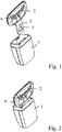
- Figur 1:
- ein Gurtschlosssystem im abgeschnallten Zustand,
- Figur 2:
- das Gurtschlosssystem im angeschnallten Zustand mit in das Gurtschloss eingesteckter Schlosszunge,
- Figur 3:
- das Gurtschlosssystem im angeschnallten Zustand ohne Gehäuse des Gurtschlosses,
- Figur 4:
- eine weitere Ausführungsform einer Schlosszunge,
- Figur 5:
- eine teilweise Querschnittsansicht durch ein Gurtschloss bei eingesteckter Schlosszunge,
- Figur 6:
- eine Detailansicht der Darstellung der
Figur 5 - Figur 7:
- eine Platine einer Schlosszunge vor der Montage mit einem einen RFID-Transponder aufweisenden Gehäuse und
- Figur 8:
- die die Platine und RFID-
Transponder gemäß Figur 7 aufweisende Schlosszunge.
- Figure 1:
- a belt lock system when the seat belt is unbuckled,
- Figure 2:
- the seat belt lock system when buckled with the tongue inserted into the seat belt lock,
- Figure 3:
- the seat belt lock system in the buckled state without the seat belt lock housing,
- Figure 4:
- another embodiment of a lock tongue,
- Figure 5:
- a partial cross-sectional view through a belt lock with the lock tongue inserted,
- Figure 6:
- a detailed view of the representation of the
Figure 5 , - Figure 7:
- a circuit board of a lock tongue prior to assembly with a housing having an RFID transponder and
- Figure 8:
- which the circuit board and RFID transponder according to
Figure 7 having lock tongue.
Das in den
In den
In
In
Nachdem das Gehäuse 8 durch Verrasten mit der Platine 5 an der Platine 5 vorfixiert ist, wird eine Umspritzung 6 aus Kunststoff ausgebildet, wobei die Umspritzung 6 das Gehäuse 8 zumindest teilweise umgibt und somit das Gehäuse 8 und den darin angeordneten RFID-Transponder an der Platine 5 abschließend fixiert.After the
- 11
- GurtschlossSeat belt buckle
- 22
- SchlosszungeLock tongue
- 33
- RFID-TransponderRFID transponder
- 44th
- RFID-LeseeinheitRFID reader
- 55
- Platinecircuit board
- 66th
- UmspritzungEncapsulation
- 77th
- KopplungsbereichCoupling area
- 88th
- Gehäusecasing
Claims (13)
- Buckle system, comprising a buckle (1) and a buckle tongue (2) which can be inserted into the buckle (1), an RFID transponder (3) being arranged in or on the buckle tongue (2) and an RFID reader unit (4) being arranged in the buckle (1) and designed in such away that coupling between the RFID reader unit (4) and the RFID transponder (3) is only possible when the buckle tongue (2) is inserted into the buckle (1), characterized in that the RFID transponder (3) is arranged in a housing (8) made of plastics material so as to be held on a metal plate (5) of the buckle tongue (2) and so as to be spaced apart from the plate (5).
- Buckle system according to claim 1, wherein the RFID transponder (3) is arranged in or on the buckle tongue (2) and the RFID reader unit (4) is arranged in the buckle (1) and designed in such a way that coupling between the RFID reader unit (4) and the RFID transponder (3) is only possible when the buckle tongue (2) is inserted into the buckle (1) with an orientation predetermined by the arrangement of the RFID transponder (3).
- Buckle system according to either claim 1 or claim 2, wherein the RFID transponder (3) is arranged in or on a portion of the buckle tongue (2), which portion can be inserted into the buckle (1).
- Buckle system according to claim 3, wherein the RFID transponder (3) is arranged in or on a metal plate (5) of the buckle tongue (2), in particular in a blind hole formed in the plate (5).
- Buckle system according to claim 3, wherein the RFID transponder (3) is arranged in or on a portion of an encapsulation (6) of the buckle tongue (2) made of plastics material, which portion, when inserted, extends into the buckle (1).
- Buckle system according to any of the preceding claims, wherein the housing (8) can be fixed to the plate (5) in a force-locked and/or form-locked manner, in particular by means of an engagement connection.
- Buckle system according to any of the preceding claims, wherein the housing (8) is at least partially encapsulated by an encapsulation (6) of the buckle tongue (2) made of plastics material.
- Buckle system according to any of the preceding claims, wherein the transmission power of the RFID reader unit (4) is so low that coupling with the RFID transponder (3) is only possible at a distance of up to 3 cm.
- Buckle system according to any of the preceding claims, wherein the buckle (1) is designed such that the radiation emitted by the RFID reader unit (4) or by the RFID transponder (3) in at least one direction is at least weakened, such that coupling of the RFID transponder (3) and the RFID reader unit (4) is not possible when the buckle tongue (2) is held on the buckle (1) from the outside.
- Buckle system according to claim 9, wherein at least one shielding panel is arranged in the buckle (1).
- Buckle system according to any of the preceding claims, wherein the RFID reader unit (4) outputs a discrete signal when coupled to the RFID transponder (3).
- Buckle system according to any of claims 1 to 10, wherein the RFID reader unit (4) can be connected to an on-board BUS system.
- Buckle system according to any of the preceding claims, wherein no additional switch or sensor is provided for detecting that the buckle tongue (2) is inserted into the buckle (1).
Applications Claiming Priority (2)
| Application Number | Priority Date | Filing Date | Title |
|---|---|---|---|
| DE102017123640.6A DE102017123640A1 (en) | 2017-10-11 | 2017-10-11 | buckle system |
| PCT/EP2018/077287 WO2019072748A1 (en) | 2017-10-11 | 2018-10-08 | Seat belt buckle system |
Publications (2)
| Publication Number | Publication Date |
|---|---|
| EP3694751A1 EP3694751A1 (en) | 2020-08-19 |
| EP3694751B1 true EP3694751B1 (en) | 2021-09-22 |
Family
ID=63857893
Family Applications (1)
| Application Number | Title | Priority Date | Filing Date |
|---|---|---|---|
| EP18786256.0A Active EP3694751B1 (en) | 2017-10-11 | 2018-10-08 | Buckle system |
Country Status (6)
| Country | Link |
|---|---|
| US (1) | US11667262B2 (en) |
| EP (1) | EP3694751B1 (en) |
| JP (1) | JP6970333B2 (en) |
| CN (1) | CN111163976B (en) |
| DE (1) | DE102017123640A1 (en) |
| WO (1) | WO2019072748A1 (en) |
Families Citing this family (5)
| Publication number | Priority date | Publication date | Assignee | Title |
|---|---|---|---|---|
| WO2019161087A1 (en) | 2018-02-17 | 2019-08-22 | Cts Corporation | Vehicle seat belt buckle with wireless latch sensor |
| US10789798B1 (en) * | 2019-05-31 | 2020-09-29 | Rockwell Automation Technologies, Inc. | Diagnostic element for validation of bolt detection of a guard locking switch in a static state |
| KR20210073683A (en) * | 2019-12-10 | 2021-06-21 | 현대자동차주식회사 | Seat belt module |
| CN113706746A (en) * | 2021-08-28 | 2021-11-26 | 四川谦泰仁投资管理有限公司 | False locking and illegal opening prevention lockset based on RFID technology |
| DE102021210252B3 (en) * | 2021-09-16 | 2023-02-23 | Autoliv Development Ab | Belt tongue, safety belt device and manufacturing method for a belt tongue |
Family Cites Families (10)
| Publication number | Priority date | Publication date | Assignee | Title |
|---|---|---|---|---|
| SE510164C2 (en) * | 1996-12-30 | 1999-04-26 | Volvo Ab | Seat belt assembly and procedure |
| US20070096891A1 (en) * | 2005-10-17 | 2007-05-03 | Sheriff Michael L | RFID buckle closure and presence sensor system for safety childseat |
| US7916008B2 (en) | 2005-12-15 | 2011-03-29 | Lear Corporation | RFID systems for vehicular applications |
| DE102006042455A1 (en) * | 2006-02-21 | 2007-08-23 | Volkswagen Ag | Seat belt buckle for motor vehicle, has guide seat belt, which is loaded mechanically by seat belt buckle and in pushing condition of guide is detected by switch |
| DE102007032171B4 (en) * | 2007-07-10 | 2009-09-17 | Key Safety Systems, Inc., Sterling Heights | Device for detecting the occupancy state of a vehicle seat |
| DE102007058277A1 (en) * | 2007-12-04 | 2009-06-10 | Trw Automotive Gmbh | The vehicle occupant protection device |
| JP2009151737A (en) * | 2007-12-21 | 2009-07-09 | Shigeyuki Koike | Electric wave shield material for preventing mutual interference by inserting between ic cards, including pasmo or suica or adhering to rear surfaces thereof |
| EP2189372B1 (en) * | 2008-11-21 | 2012-06-13 | Deutsche Telekom AG | Method and system for passenger seat belt verification |
| CN106274792B (en) * | 2015-05-11 | 2020-03-06 | 奥托立夫开发公司 | Seatbelt unfastening warning system and method for vehicle |
| US10315620B1 (en) * | 2017-12-08 | 2019-06-11 | International Business Machines Corporation | Method, system, and computer program product for detection of securely fastened seat belts |
-
2017
- 2017-10-11 DE DE102017123640.6A patent/DE102017123640A1/en active Pending
-
2018
- 2018-10-08 US US16/755,200 patent/US11667262B2/en active Active
- 2018-10-08 WO PCT/EP2018/077287 patent/WO2019072748A1/en unknown
- 2018-10-08 CN CN201880064184.4A patent/CN111163976B/en active Active
- 2018-10-08 EP EP18786256.0A patent/EP3694751B1/en active Active
- 2018-10-08 JP JP2020520287A patent/JP6970333B2/en active Active
Also Published As
| Publication number | Publication date |
|---|---|
| JP2021507842A (en) | 2021-02-25 |
| CN111163976B (en) | 2023-01-20 |
| WO2019072748A1 (en) | 2019-04-18 |
| EP3694751A1 (en) | 2020-08-19 |
| US20200254966A1 (en) | 2020-08-13 |
| JP6970333B2 (en) | 2021-11-24 |
| US11667262B2 (en) | 2023-06-06 |
| DE102017123640A1 (en) | 2019-04-11 |
| CN111163976A (en) | 2020-05-15 |
Similar Documents
| Publication | Publication Date | Title |
|---|---|---|
| EP3694751B1 (en) | Buckle system | |
| DE102005059715B4 (en) | Method and device for locating the position of wheels of a motor vehicle | |
| EP2883273B1 (en) | Electrical connector housing having an rfid transponder | |
| DE3921893C2 (en) | Electronic identification system, in particular for actuating steering lock theft locks, door locks and other automotive applications | |
| EP3261060B1 (en) | Methods for controlling access in an access control system for persons or vehicles and access control system | |
| DE69721815T2 (en) | METHOD AND DEVICE FOR SEAT BELTS | |
| DE112016002538T5 (en) | Wireless vehicle seat sensor unit with removable vehicle seat accommodation | |
| DE102007058278A1 (en) | Seat e.g. child seat, belt system for use in motor vehicle, has reader arranged on transponder, and recognizing pre-determined influence of transponder or presence and absence of transponder that is coupled to component of system | |
| DE19818263A1 (en) | Device for a remote controllable access control device for motor vehicles | |
| DE102015204815B4 (en) | Seat belt device for a vehicle | |
| DE102005011042A1 (en) | Inductive component, in particular for an electronic key | |
| DE102007058277A1 (en) | The vehicle occupant protection device | |
| EP3617009B1 (en) | System and method for detecting the locking and / or functional state of a safety belt system | |
| DE102007023580A1 (en) | Passenger protection device e.g. belt retractor, has radio frequency identification transponder indicating characteristic reaction, which is detected from reader, where reaction of transponder is caused by external field changes | |
| EP1398434A2 (en) | Door handle device for motor vehicle | |
| DE102019103460A1 (en) | Seat belt device with an electronic device | |
| EP2160744A1 (en) | Electronic status detection device | |
| DE102007036485A1 (en) | Electronic key for locking system of motor vehicle, has illuminant fixed to actuating unit for illuminating actuating unit and partially made of transparent material in such a manner that actuating unit serves as light conductor | |
| DE102007017411B4 (en) | Housing, in particular for an electronic key | |
| DE102005031997A1 (en) | Locking system for motor vehicle has transmitter of first control device allocated to at least two areas of vehicle, and operating component for release of signal from first control device is allocated to each aforesaid area | |
| DE102019113893A1 (en) | Seat belt | |
| DE102016008624A1 (en) | Device and method for operating a vehicle access and / or driving authorization system | |
| DE102007029279A1 (en) | Access controlling system for use in motor vehicle, has control device coupled with coupling device, where communication between sensor and control device is realized by signal section for verification of authorization to access | |
| DE102004007679A1 (en) | Motor vehicle security control system, has a central control unit that is linked to control units for individual component actuators, e.g. door locks, via a bus system and that manages and controls their anti-theft functions | |
| DE102014005573A1 (en) | Method for determining position |
Legal Events
| Date | Code | Title | Description |
|---|---|---|---|
| STAA | Information on the status of an ep patent application or granted ep patent |
Free format text: STATUS: UNKNOWN |
|
| STAA | Information on the status of an ep patent application or granted ep patent |
Free format text: STATUS: THE INTERNATIONAL PUBLICATION HAS BEEN MADE |
|
| PUAI | Public reference made under article 153(3) epc to a published international application that has entered the european phase |
Free format text: ORIGINAL CODE: 0009012 |
|
| STAA | Information on the status of an ep patent application or granted ep patent |
Free format text: STATUS: REQUEST FOR EXAMINATION WAS MADE |
|
| 17P | Request for examination filed |
Effective date: 20200507 |
|
| AK | Designated contracting states |
Kind code of ref document: A1 Designated state(s): AL AT BE BG CH CY CZ DE DK EE ES FI FR GB GR HR HU IE IS IT LI LT LU LV MC MK MT NL NO PL PT RO RS SE SI SK SM TR |
|
| AX | Request for extension of the european patent |
Extension state: BA ME |
|
| RIN1 | Information on inventor provided before grant (corrected) |
Inventor name: OTS, AIDU Inventor name: SCHARNBERG, OLE Inventor name: RUCHHOEFT, STEPHAN Inventor name: MELNIKOVA, LARISSA |
|
| DAV | Request for validation of the european patent (deleted) | ||
| DAX | Request for extension of the european patent (deleted) | ||
| GRAP | Despatch of communication of intention to grant a patent |
Free format text: ORIGINAL CODE: EPIDOSNIGR1 |
|
| STAA | Information on the status of an ep patent application or granted ep patent |
Free format text: STATUS: GRANT OF PATENT IS INTENDED |
|
| INTG | Intention to grant announced |
Effective date: 20210517 |
|
| RIN1 | Information on inventor provided before grant (corrected) |
Inventor name: RUCHHOEFT, STEPHAN Inventor name: SCHARNBERG, OLE Inventor name: MELNIKOVA, LARISSA Inventor name: OTS, AIDU |
|
| GRAS | Grant fee paid |
Free format text: ORIGINAL CODE: EPIDOSNIGR3 |
|
| GRAA | (expected) grant |
Free format text: ORIGINAL CODE: 0009210 |
|
| STAA | Information on the status of an ep patent application or granted ep patent |
Free format text: STATUS: THE PATENT HAS BEEN GRANTED |
|
| AK | Designated contracting states |
Kind code of ref document: B1 Designated state(s): AL AT BE BG CH CY CZ DE DK EE ES FI FR GB GR HR HU IE IS IT LI LT LU LV MC MK MT NL NO PL PT RO RS SE SI SK SM TR |
|
| REG | Reference to a national code |
Ref country code: GB Ref legal event code: FG4D Free format text: NOT ENGLISH |
|
| REG | Reference to a national code |
Ref country code: IE Ref legal event code: FG4D Free format text: LANGUAGE OF EP DOCUMENT: GERMAN |
|
| REG | Reference to a national code |
Ref country code: DE Ref legal event code: R096 Ref document number: 502018007195 Country of ref document: DE |
|
| REG | Reference to a national code |
Ref country code: CH Ref legal event code: EP Ref country code: AT Ref legal event code: REF Ref document number: 1432096 Country of ref document: AT Kind code of ref document: T Effective date: 20211015 |
|
| REG | Reference to a national code |
Ref country code: LT Ref legal event code: MG9D |
|
| REG | Reference to a national code |
Ref country code: NL Ref legal event code: MP Effective date: 20210922 |
|
| PG25 | Lapsed in a contracting state [announced via postgrant information from national office to epo] |
Ref country code: SE Free format text: LAPSE BECAUSE OF FAILURE TO SUBMIT A TRANSLATION OF THE DESCRIPTION OR TO PAY THE FEE WITHIN THE PRESCRIBED TIME-LIMIT Effective date: 20210922 Ref country code: RS Free format text: LAPSE BECAUSE OF FAILURE TO SUBMIT A TRANSLATION OF THE DESCRIPTION OR TO PAY THE FEE WITHIN THE PRESCRIBED TIME-LIMIT Effective date: 20210922 Ref country code: HR Free format text: LAPSE BECAUSE OF FAILURE TO SUBMIT A TRANSLATION OF THE DESCRIPTION OR TO PAY THE FEE WITHIN THE PRESCRIBED TIME-LIMIT Effective date: 20210922 Ref country code: FI Free format text: LAPSE BECAUSE OF FAILURE TO SUBMIT A TRANSLATION OF THE DESCRIPTION OR TO PAY THE FEE WITHIN THE PRESCRIBED TIME-LIMIT Effective date: 20210922 Ref country code: LT Free format text: LAPSE BECAUSE OF FAILURE TO SUBMIT A TRANSLATION OF THE DESCRIPTION OR TO PAY THE FEE WITHIN THE PRESCRIBED TIME-LIMIT Effective date: 20210922 Ref country code: BG Free format text: LAPSE BECAUSE OF FAILURE TO SUBMIT A TRANSLATION OF THE DESCRIPTION OR TO PAY THE FEE WITHIN THE PRESCRIBED TIME-LIMIT Effective date: 20211222 Ref country code: NO Free format text: LAPSE BECAUSE OF FAILURE TO SUBMIT A TRANSLATION OF THE DESCRIPTION OR TO PAY THE FEE WITHIN THE PRESCRIBED TIME-LIMIT Effective date: 20211222 |
|
| PG25 | Lapsed in a contracting state [announced via postgrant information from national office to epo] |
Ref country code: LV Free format text: LAPSE BECAUSE OF FAILURE TO SUBMIT A TRANSLATION OF THE DESCRIPTION OR TO PAY THE FEE WITHIN THE PRESCRIBED TIME-LIMIT Effective date: 20210922 Ref country code: GR Free format text: LAPSE BECAUSE OF FAILURE TO SUBMIT A TRANSLATION OF THE DESCRIPTION OR TO PAY THE FEE WITHIN THE PRESCRIBED TIME-LIMIT Effective date: 20211223 |
|
| REG | Reference to a national code |
Ref country code: CH Ref legal event code: PL |
|
| PG25 | Lapsed in a contracting state [announced via postgrant information from national office to epo] |
Ref country code: IS Free format text: LAPSE BECAUSE OF FAILURE TO SUBMIT A TRANSLATION OF THE DESCRIPTION OR TO PAY THE FEE WITHIN THE PRESCRIBED TIME-LIMIT Effective date: 20220122 Ref country code: SK Free format text: LAPSE BECAUSE OF FAILURE TO SUBMIT A TRANSLATION OF THE DESCRIPTION OR TO PAY THE FEE WITHIN THE PRESCRIBED TIME-LIMIT Effective date: 20210922 Ref country code: RO Free format text: LAPSE BECAUSE OF FAILURE TO SUBMIT A TRANSLATION OF THE DESCRIPTION OR TO PAY THE FEE WITHIN THE PRESCRIBED TIME-LIMIT Effective date: 20210922 Ref country code: PT Free format text: LAPSE BECAUSE OF FAILURE TO SUBMIT A TRANSLATION OF THE DESCRIPTION OR TO PAY THE FEE WITHIN THE PRESCRIBED TIME-LIMIT Effective date: 20220124 Ref country code: PL Free format text: LAPSE BECAUSE OF FAILURE TO SUBMIT A TRANSLATION OF THE DESCRIPTION OR TO PAY THE FEE WITHIN THE PRESCRIBED TIME-LIMIT Effective date: 20210922 Ref country code: NL Free format text: LAPSE BECAUSE OF FAILURE TO SUBMIT A TRANSLATION OF THE DESCRIPTION OR TO PAY THE FEE WITHIN THE PRESCRIBED TIME-LIMIT Effective date: 20210922 Ref country code: ES Free format text: LAPSE BECAUSE OF FAILURE TO SUBMIT A TRANSLATION OF THE DESCRIPTION OR TO PAY THE FEE WITHIN THE PRESCRIBED TIME-LIMIT Effective date: 20210922 Ref country code: EE Free format text: LAPSE BECAUSE OF FAILURE TO SUBMIT A TRANSLATION OF THE DESCRIPTION OR TO PAY THE FEE WITHIN THE PRESCRIBED TIME-LIMIT Effective date: 20210922 Ref country code: CZ Free format text: LAPSE BECAUSE OF FAILURE TO SUBMIT A TRANSLATION OF THE DESCRIPTION OR TO PAY THE FEE WITHIN THE PRESCRIBED TIME-LIMIT Effective date: 20210922 Ref country code: AL Free format text: LAPSE BECAUSE OF FAILURE TO SUBMIT A TRANSLATION OF THE DESCRIPTION OR TO PAY THE FEE WITHIN THE PRESCRIBED TIME-LIMIT Effective date: 20210922 |
|
| REG | Reference to a national code |
Ref country code: DE Ref legal event code: R097 Ref document number: 502018007195 Country of ref document: DE Ref country code: BE Ref legal event code: MM Effective date: 20211031 |
|
| PG25 | Lapsed in a contracting state [announced via postgrant information from national office to epo] |
Ref country code: MC Free format text: LAPSE BECAUSE OF FAILURE TO SUBMIT A TRANSLATION OF THE DESCRIPTION OR TO PAY THE FEE WITHIN THE PRESCRIBED TIME-LIMIT Effective date: 20210922 |
|
| PG25 | Lapsed in a contracting state [announced via postgrant information from national office to epo] |
Ref country code: LU Free format text: LAPSE BECAUSE OF NON-PAYMENT OF DUE FEES Effective date: 20211008 Ref country code: DK Free format text: LAPSE BECAUSE OF FAILURE TO SUBMIT A TRANSLATION OF THE DESCRIPTION OR TO PAY THE FEE WITHIN THE PRESCRIBED TIME-LIMIT Effective date: 20210922 Ref country code: BE Free format text: LAPSE BECAUSE OF NON-PAYMENT OF DUE FEES Effective date: 20211031 |
|
| PLBE | No opposition filed within time limit |
Free format text: ORIGINAL CODE: 0009261 |
|
| STAA | Information on the status of an ep patent application or granted ep patent |
Free format text: STATUS: NO OPPOSITION FILED WITHIN TIME LIMIT |
|
| 26N | No opposition filed |
Effective date: 20220623 |
|
| PG25 | Lapsed in a contracting state [announced via postgrant information from national office to epo] |
Ref country code: LI Free format text: LAPSE BECAUSE OF NON-PAYMENT OF DUE FEES Effective date: 20211031 Ref country code: CH Free format text: LAPSE BECAUSE OF NON-PAYMENT OF DUE FEES Effective date: 20211031 |
|
| PG25 | Lapsed in a contracting state [announced via postgrant information from national office to epo] |
Ref country code: IE Free format text: LAPSE BECAUSE OF NON-PAYMENT OF DUE FEES Effective date: 20211008 |
|
| PG25 | Lapsed in a contracting state [announced via postgrant information from national office to epo] |
Ref country code: SI Free format text: LAPSE BECAUSE OF FAILURE TO SUBMIT A TRANSLATION OF THE DESCRIPTION OR TO PAY THE FEE WITHIN THE PRESCRIBED TIME-LIMIT Effective date: 20210922 |
|
| PG25 | Lapsed in a contracting state [announced via postgrant information from national office to epo] |
Ref country code: IT Free format text: LAPSE BECAUSE OF FAILURE TO SUBMIT A TRANSLATION OF THE DESCRIPTION OR TO PAY THE FEE WITHIN THE PRESCRIBED TIME-LIMIT Effective date: 20210922 |
|
| P01 | Opt-out of the competence of the unified patent court (upc) registered |
Effective date: 20230507 |
|
| PG25 | Lapsed in a contracting state [announced via postgrant information from national office to epo] |
Ref country code: CY Free format text: LAPSE BECAUSE OF FAILURE TO SUBMIT A TRANSLATION OF THE DESCRIPTION OR TO PAY THE FEE WITHIN THE PRESCRIBED TIME-LIMIT Effective date: 20210922 |
|
| PG25 | Lapsed in a contracting state [announced via postgrant information from national office to epo] |
Ref country code: SM Free format text: LAPSE BECAUSE OF FAILURE TO SUBMIT A TRANSLATION OF THE DESCRIPTION OR TO PAY THE FEE WITHIN THE PRESCRIBED TIME-LIMIT Effective date: 20210922 Ref country code: HU Free format text: LAPSE BECAUSE OF FAILURE TO SUBMIT A TRANSLATION OF THE DESCRIPTION OR TO PAY THE FEE WITHIN THE PRESCRIBED TIME-LIMIT; INVALID AB INITIO Effective date: 20181008 |
|
| PGFP | Annual fee paid to national office [announced via postgrant information from national office to epo] |
Ref country code: GB Payment date: 20231024 Year of fee payment: 6 |
|
| PGFP | Annual fee paid to national office [announced via postgrant information from national office to epo] |
Ref country code: FR Payment date: 20231026 Year of fee payment: 6 Ref country code: DE Payment date: 20231027 Year of fee payment: 6 |