EP3694702B1 - Kronenverstärkung für einen reifen eines traktorartigen landwirtschaftlichen fahrzeugs - Google Patents
Kronenverstärkung für einen reifen eines traktorartigen landwirtschaftlichen fahrzeugs Download PDFInfo
- Publication number
- EP3694702B1 EP3694702B1 EP18792976.5A EP18792976A EP3694702B1 EP 3694702 B1 EP3694702 B1 EP 3694702B1 EP 18792976 A EP18792976 A EP 18792976A EP 3694702 B1 EP3694702 B1 EP 3694702B1
- Authority
- EP
- European Patent Office
- Prior art keywords
- working
- angle
- layers
- circumferential
- tire
- Prior art date
- Legal status (The legal status is an assumption and is not a legal conclusion. Google has not performed a legal analysis and makes no representation as to the accuracy of the status listed.)
- Active
Links
- 230000002787 reinforcement Effects 0.000 title claims description 100
- 239000004753 textile Substances 0.000 claims description 20
- 238000004804 winding Methods 0.000 claims description 20
- 238000005520 cutting process Methods 0.000 claims description 9
- 239000002184 metal Substances 0.000 claims description 6
- 229910052751 metal Inorganic materials 0.000 claims description 6
- 229910000831 Steel Inorganic materials 0.000 claims description 3
- 239000010959 steel Substances 0.000 claims description 3
- 150000001875 compounds Chemical class 0.000 claims 1
- 239000000203 mixture Substances 0.000 description 12
- 229920000728 polyester Polymers 0.000 description 11
- 238000004519 manufacturing process Methods 0.000 description 10
- 229920000297 Rayon Polymers 0.000 description 9
- 239000011248 coating agent Substances 0.000 description 9
- 238000000576 coating method Methods 0.000 description 9
- 230000008602 contraction Effects 0.000 description 9
- 239000002964 rayon Substances 0.000 description 9
- 239000004952 Polyamide Substances 0.000 description 5
- 239000002131 composite material Substances 0.000 description 5
- 238000000034 method Methods 0.000 description 5
- 229920002647 polyamide Polymers 0.000 description 5
- PPBRXRYQALVLMV-UHFFFAOYSA-N Styrene Chemical compound C=CC1=CC=CC=C1 PPBRXRYQALVLMV-UHFFFAOYSA-N 0.000 description 4
- 239000011324 bead Substances 0.000 description 4
- 238000005096 rolling process Methods 0.000 description 4
- 241000531908 Aramides Species 0.000 description 3
- 239000003963 antioxidant agent Substances 0.000 description 3
- 230000003078 antioxidant effect Effects 0.000 description 3
- 229920003235 aromatic polyamide Polymers 0.000 description 3
- 230000015556 catabolic process Effects 0.000 description 3
- 238000009434 installation Methods 0.000 description 3
- QAZLUNIWYYOJPC-UHFFFAOYSA-M sulfenamide Chemical compound [Cl-].COC1=C(C)C=[N+]2C3=NC4=CC=C(OC)C=C4N3SCC2=C1C QAZLUNIWYYOJPC-UHFFFAOYSA-M 0.000 description 3
- KGRVJHAUYBGFFP-UHFFFAOYSA-N 2,2'-Methylenebis(4-methyl-6-tert-butylphenol) Chemical compound CC(C)(C)C1=CC(C)=CC(CC=2C(=C(C=C(C)C=2)C(C)(C)C)O)=C1O KGRVJHAUYBGFFP-UHFFFAOYSA-N 0.000 description 2
- 239000004677 Nylon Substances 0.000 description 2
- XLOMVQKBTHCTTD-UHFFFAOYSA-N Zinc monoxide Chemical compound [Zn]=O XLOMVQKBTHCTTD-UHFFFAOYSA-N 0.000 description 2
- 238000004873 anchoring Methods 0.000 description 2
- 239000004760 aramid Substances 0.000 description 2
- 239000006229 carbon black Substances 0.000 description 2
- 230000000536 complexating effect Effects 0.000 description 2
- 230000006835 compression Effects 0.000 description 2
- 238000007906 compression Methods 0.000 description 2
- 238000005336 cracking Methods 0.000 description 2
- 238000006731 degradation reaction Methods 0.000 description 2
- 230000000694 effects Effects 0.000 description 2
- 229920001971 elastomer Polymers 0.000 description 2
- 239000000806 elastomer Substances 0.000 description 2
- 238000003475 lamination Methods 0.000 description 2
- 239000000463 material Substances 0.000 description 2
- 229920001778 nylon Polymers 0.000 description 2
- 229920006149 polyester-amide block copolymer Polymers 0.000 description 2
- 239000011347 resin Substances 0.000 description 2
- 229920005989 resin Polymers 0.000 description 2
- KKEYFWRCBNTPAC-UHFFFAOYSA-L terephthalate(2-) Chemical compound [O-]C(=O)C1=CC=C(C([O-])=O)C=C1 KKEYFWRCBNTPAC-UHFFFAOYSA-L 0.000 description 2
- 238000011144 upstream manufacturing Methods 0.000 description 2
- 125000000391 vinyl group Chemical group [H]C([*])=C([H])[H] 0.000 description 2
- 229920002554 vinyl polymer Polymers 0.000 description 2
- 238000003466 welding Methods 0.000 description 2
- GEYOCULIXLDCMW-UHFFFAOYSA-N 1,2-phenylenediamine Chemical compound NC1=CC=CC=C1N GEYOCULIXLDCMW-UHFFFAOYSA-N 0.000 description 1
- YCAIAEVWVDGLAV-UHFFFAOYSA-N 2-tert-butyl-1,3-benzothiazole Chemical compound C1=CC=C2SC(C(C)(C)C)=NC2=C1 YCAIAEVWVDGLAV-UHFFFAOYSA-N 0.000 description 1
- 208000029497 Elastoma Diseases 0.000 description 1
- 244000043261 Hevea brasiliensis Species 0.000 description 1
- 235000021355 Stearic acid Nutrition 0.000 description 1
- NINIDFKCEFEMDL-UHFFFAOYSA-N Sulfur Chemical compound [S] NINIDFKCEFEMDL-UHFFFAOYSA-N 0.000 description 1
- SFBGWCMLAKEECF-UHFFFAOYSA-N aniline;propan-2-one Chemical compound CC(C)=O.NC1=CC=CC=C1 SFBGWCMLAKEECF-UHFFFAOYSA-N 0.000 description 1
- 239000000470 constituent Substances 0.000 description 1
- 238000009826 distribution Methods 0.000 description 1
- 229940082150 encore Drugs 0.000 description 1
- 230000014509 gene expression Effects 0.000 description 1
- 230000000977 initiatory effect Effects 0.000 description 1
- 230000001788 irregular Effects 0.000 description 1
- 229920003052 natural elastomer Polymers 0.000 description 1
- 229920001194 natural rubber Polymers 0.000 description 1
- QIQXTHQIDYTFRH-UHFFFAOYSA-N octadecanoic acid Chemical compound CCCCCCCCCCCCCCCCCC(O)=O QIQXTHQIDYTFRH-UHFFFAOYSA-N 0.000 description 1
- OQCDKBAXFALNLD-UHFFFAOYSA-N octadecanoic acid Natural products CCCCCCCC(C)CCCCCCCCC(O)=O OQCDKBAXFALNLD-UHFFFAOYSA-N 0.000 description 1
- 230000008520 organization Effects 0.000 description 1
- 230000003647 oxidation Effects 0.000 description 1
- 238000007254 oxidation reaction Methods 0.000 description 1
- 238000002360 preparation method Methods 0.000 description 1
- 230000001681 protective effect Effects 0.000 description 1
- 238000007585 pull-off test Methods 0.000 description 1
- 230000003014 reinforcing effect Effects 0.000 description 1
- 238000000926 separation method Methods 0.000 description 1
- 238000007493 shaping process Methods 0.000 description 1
- 230000035939 shock Effects 0.000 description 1
- 238000009987 spinning Methods 0.000 description 1
- 239000008117 stearic acid Substances 0.000 description 1
- 229910052717 sulfur Inorganic materials 0.000 description 1
- 239000011593 sulfur Substances 0.000 description 1
- 239000011787 zinc oxide Substances 0.000 description 1
Images
Classifications
-
- B—PERFORMING OPERATIONS; TRANSPORTING
- B60—VEHICLES IN GENERAL
- B60C—VEHICLE TYRES; TYRE INFLATION; TYRE CHANGING; CONNECTING VALVES TO INFLATABLE ELASTIC BODIES IN GENERAL; DEVICES OR ARRANGEMENTS RELATED TO TYRES
- B60C9/00—Reinforcements or ply arrangement of pneumatic tyres
- B60C9/18—Structure or arrangement of belts or breakers, crown-reinforcing or cushioning layers
- B60C9/20—Structure or arrangement of belts or breakers, crown-reinforcing or cushioning layers built-up from rubberised plies each having all cords arranged substantially parallel
- B60C9/2003—Structure or arrangement of belts or breakers, crown-reinforcing or cushioning layers built-up from rubberised plies each having all cords arranged substantially parallel characterised by the materials of the belt cords
-
- B—PERFORMING OPERATIONS; TRANSPORTING
- B60—VEHICLES IN GENERAL
- B60C—VEHICLE TYRES; TYRE INFLATION; TYRE CHANGING; CONNECTING VALVES TO INFLATABLE ELASTIC BODIES IN GENERAL; DEVICES OR ARRANGEMENTS RELATED TO TYRES
- B60C9/00—Reinforcements or ply arrangement of pneumatic tyres
- B60C9/18—Structure or arrangement of belts or breakers, crown-reinforcing or cushioning layers
- B60C9/20—Structure or arrangement of belts or breakers, crown-reinforcing or cushioning layers built-up from rubberised plies each having all cords arranged substantially parallel
-
- B—PERFORMING OPERATIONS; TRANSPORTING
- B29—WORKING OF PLASTICS; WORKING OF SUBSTANCES IN A PLASTIC STATE IN GENERAL
- B29D—PRODUCING PARTICULAR ARTICLES FROM PLASTICS OR FROM SUBSTANCES IN A PLASTIC STATE
- B29D30/00—Producing pneumatic or solid tyres or parts thereof
- B29D30/06—Pneumatic tyres or parts thereof (e.g. produced by casting, moulding, compression moulding, injection moulding, centrifugal casting)
- B29D30/08—Building tyres
- B29D30/10—Building tyres on round cores, i.e. the shape of the core is approximately identical with the shape of the completed tyre
- B29D30/16—Applying the layers; Guiding or stretching the layers during application
- B29D30/1621—Applying the layers; Guiding or stretching the layers during application by feeding a continuous band and winding it spirally, i.e. the band is fed without relative movement along the core axis, to form an annular element
-
- B—PERFORMING OPERATIONS; TRANSPORTING
- B29—WORKING OF PLASTICS; WORKING OF SUBSTANCES IN A PLASTIC STATE IN GENERAL
- B29D—PRODUCING PARTICULAR ARTICLES FROM PLASTICS OR FROM SUBSTANCES IN A PLASTIC STATE
- B29D30/00—Producing pneumatic or solid tyres or parts thereof
- B29D30/06—Pneumatic tyres or parts thereof (e.g. produced by casting, moulding, compression moulding, injection moulding, centrifugal casting)
- B29D30/08—Building tyres
- B29D30/20—Building tyres by the flat-tyre method, i.e. building on cylindrical drums
- B29D30/30—Applying the layers; Guiding or stretching the layers during application
- B29D30/3021—Applying the layers; Guiding or stretching the layers during application by feeding a continuous band and winding it spirally, i.e. the band is fed without relative movement along the drum axis, to form an annular element
-
- B—PERFORMING OPERATIONS; TRANSPORTING
- B29—WORKING OF PLASTICS; WORKING OF SUBSTANCES IN A PLASTIC STATE IN GENERAL
- B29D—PRODUCING PARTICULAR ARTICLES FROM PLASTICS OR FROM SUBSTANCES IN A PLASTIC STATE
- B29D30/00—Producing pneumatic or solid tyres or parts thereof
- B29D30/06—Pneumatic tyres or parts thereof (e.g. produced by casting, moulding, compression moulding, injection moulding, centrifugal casting)
- B29D30/70—Annular breakers
-
- B—PERFORMING OPERATIONS; TRANSPORTING
- B60—VEHICLES IN GENERAL
- B60C—VEHICLE TYRES; TYRE INFLATION; TYRE CHANGING; CONNECTING VALVES TO INFLATABLE ELASTIC BODIES IN GENERAL; DEVICES OR ARRANGEMENTS RELATED TO TYRES
- B60C9/00—Reinforcements or ply arrangement of pneumatic tyres
- B60C9/18—Structure or arrangement of belts or breakers, crown-reinforcing or cushioning layers
- B60C9/20—Structure or arrangement of belts or breakers, crown-reinforcing or cushioning layers built-up from rubberised plies each having all cords arranged substantially parallel
- B60C2009/2012—Structure or arrangement of belts or breakers, crown-reinforcing or cushioning layers built-up from rubberised plies each having all cords arranged substantially parallel with particular configuration of the belt cords in the respective belt layers
- B60C2009/2016—Structure or arrangement of belts or breakers, crown-reinforcing or cushioning layers built-up from rubberised plies each having all cords arranged substantially parallel with particular configuration of the belt cords in the respective belt layers comprising cords at an angle of 10 to 30 degrees to the circumferential direction
-
- B—PERFORMING OPERATIONS; TRANSPORTING
- B60—VEHICLES IN GENERAL
- B60C—VEHICLE TYRES; TYRE INFLATION; TYRE CHANGING; CONNECTING VALVES TO INFLATABLE ELASTIC BODIES IN GENERAL; DEVICES OR ARRANGEMENTS RELATED TO TYRES
- B60C9/00—Reinforcements or ply arrangement of pneumatic tyres
- B60C9/18—Structure or arrangement of belts or breakers, crown-reinforcing or cushioning layers
- B60C9/20—Structure or arrangement of belts or breakers, crown-reinforcing or cushioning layers built-up from rubberised plies each having all cords arranged substantially parallel
- B60C2009/2012—Structure or arrangement of belts or breakers, crown-reinforcing or cushioning layers built-up from rubberised plies each having all cords arranged substantially parallel with particular configuration of the belt cords in the respective belt layers
- B60C2009/2019—Structure or arrangement of belts or breakers, crown-reinforcing or cushioning layers built-up from rubberised plies each having all cords arranged substantially parallel with particular configuration of the belt cords in the respective belt layers comprising cords at an angle of 30 to 60 degrees to the circumferential direction
-
- B—PERFORMING OPERATIONS; TRANSPORTING
- B60—VEHICLES IN GENERAL
- B60C—VEHICLE TYRES; TYRE INFLATION; TYRE CHANGING; CONNECTING VALVES TO INFLATABLE ELASTIC BODIES IN GENERAL; DEVICES OR ARRANGEMENTS RELATED TO TYRES
- B60C2200/00—Tyres specially adapted for particular applications
- B60C2200/08—Tyres specially adapted for particular applications for agricultural vehicles
Definitions
- the present invention relates to a radial tire, intended to equip a heavy vehicle of agricultural type, and relates more particularly to the working reinforcement of such a tire.
- Such tires for agricultural vehicles are intended to be mounted on 16 to 42 inch rims. Their dimensional specifications are accessible in dedicated standards, such as the ETRTO (European Tire and Rim Technical Organization) standard. Although not limited to this type of application, the invention is more particularly described for a large-dimension radial tire, with a nominal section width of between 320 mm and 650 mm, and an outside diameter of the tire inflated to its pressure. nominal and mounted on its rim between 822 mm and 1913 mm.
- the tire described in the invention is more particularly intended to equip a range of agricultural tractors the power of which is between 80 CV and 200 CV. It follows that the load capacity of such a tire varies from 975 to 4125 kilograms for a nominal inflation pressure of 160 kPa. Furthermore, this tire must be able to reach a speed of 65 km / h on the road.
- a tire Since a tire has a geometry of revolution relative to an axis of rotation, the geometry of the tire is generally described in a meridian plane containing the axis of rotation of the tire.
- the radial, axial and circumferential directions respectively denote the directions perpendicular to the axis of rotation of the tire, parallel to the axis of rotation of the tire and perpendicular to the meridian plane.
- the circumferential direction is tangent to the circumference of the tire.
- the expressions “radially inside” and “radially outside” respectively mean “closer”, respectively “more distant from the axis of rotation of the tire”.
- axially inner respectively “axially outer” is meant “closer”, respectively “farther from the equatorial plane of the tire", the equatorial plane of the tire being the plane passing through the middle of the tread surface and perpendicular to the tire. the axis of rotation.
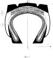
- a tire comprises a tread intended to come into contact with a ground via a tread surface, both of which axial ends are connected by means of two sidewalls with two beads providing the mechanical connection between the tire and the rim on which it is intended to be mounted.
- a radial tire further comprises a reinforcement, consisting of a crown reinforcement, radially inside the tread, and a carcass reinforcement, radially inside the crown reinforcement.
- the carcass reinforcement of a radial tire for this type of vehicle usually comprises at least one carcass layer comprising reinforcements, coated with a polymeric material of the elastomeric or elastomeric type called the coating mixture.
- a carcass layer comprises a main part, connecting the two beads to each other and generally wound, in each bead, from the inside to the outside of the tire around a circumferential reinforcing element most often metallic called bead wire, to form a turnaround.
- the reinforcements of a carcass layer are substantially parallel to each other and form, with the circumferential direction, an angle of between 85 ° and 95 °.
- the crown reinforcement of a radial tire for a heavy vehicle of the agricultural type comprises a superposition of crown layers extending circumferentially, radially outside the carcass reinforcement.
- Each top layer consists of textile or metal reinforcements, parallel to each other and coated with a polymeric material of the elastomer type or coating mixture.
- the function of the working reinforcement is to surround the tire and to give it rigidity and road holding. It incorporates both mechanical inflation stresses, generated by the inflation pressure of the tire and transmitted by the carcass reinforcement, and mechanical rolling stresses, generated by the rolling of the tire on ground and transmitted by the tread. . It must also resist oxidation and shocks and perforations, thanks to its intrinsic design and that of the protective frame.
- the working layers also have the function of giving the tire a high rigidity or drift thrust, necessary in a known manner for obtaining good road behavior on a motor vehicle.
- Other performances are also linked to the mechanical functioning of the working layers, such as rolling resistance, high speed endurance or even breaking energy (breaking energy test).
- the reinforcements of the working layers can be of the metallic type, such as steel, or of the textile type, such as polyester terephthalate (PET), polyamide, aramid, or even rayon.
- PET polyester terephthalate
- the working layer is characterized by geometric and physical parameters which determine its mechanical behavior. These parameters are, for example, the thickness of the working layer which is directly related to the diameter of the reinforcements or even the density of reinforcements of the layer which is the number of reinforcements in a section of layer with a width of 1 dm.
- the breaking force of the reinforcement is used to size the working layer with respect to the mechanical stresses undergone.
- reinforcements or cables will be used interchangeably depending on the context.
- Polyester or polyamide textile cables have a thermosensitive behavior, which means that their mechanical properties change significantly with temperature.
- Standard contraction is the shrinkage that a polyester or polyamide rope undergoes at a temperature of 180 ° C under a standardized standard pretension.
- HMLS High Modulus Low Shrinkage
- the quality of the adhesion between the elastomeric coating mixture and the textile reinforcement is determined by a test in which the force necessary to extract sections of cords from the vulcanized elastomeric coating mixture is measured. This tearing force is measured in Newtons per torn cable.
- the working reinforcement of a tire for an agricultural vehicle is most often composed of working layers with textile reinforcements, which requires the presence of a plurality of working layers and generally more than two working layers, taking into account the level of mechanical stresses to which the tire is subjected.
- each working layer is wound individually around a finishing drum, radially outside the reinforcement of the tire. carcass.
- a welding of the working layer by overlap is carried out, by superimposing a first circumferential end of the working layer on a second circumferential end over a given length of overlap.
- the large number of working layers with textile reinforcements leads to local extra thicknesses in the circumferential direction corresponding to each of the welds. These extra thicknesses not only degrade the uniformity of the tire, but also its resistance to endurance. The degradation of the uniformity of the tire is manifested in the handling of the vehicle, which can prove to be dangerous. The welds lead to local excess thicknesses which constitute points of mechanical weakness of the tire.
- the degradation of the circumferential uniformity of the tire results from an irregular distribution of the mass of the tire around the axis of rotation. More precisely, the uniformity can be at least in part characterized by a criterion of runout of the tire.
- the runout is the variation in the radius of the tire in millimeters measured perpendicular to the axis of rotation on the circumference, at the surface of the tread, without taking into account the influence of the grooves and other hollows located on the tread bearing of the tire.
- the peak-to-peak runout (FRCL) corresponds, over one revolution of the wheel, to the difference between the maximum and minimum values of the measured runout.
- the ISO 13326 standard defines the principle of measuring uniformity criteria.
- the endurance is evaluated by a rolling test of the tire which is inflated to its nominal pressure increased by 1 bar, mounted on its nominal rim and crushed on a flywheel driven at a constant rotational speed.
- the tire undergoes loading cycles in stages, at load levels up to twice its maximum theoretical load.
- the test is passed if the life of the tire is greater than a threshold time, expressed in hours and fixed in advance.
- the document FR 2 080 673 A1 describes a tire provided with a working reinforcement formed by a circumferential spiral winding of a multilayer component.
- the inventors set themselves the objective of improving the endurance of a tire for an agricultural vehicle comprising a working reinforcement which consists of at least two working layers.
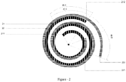
- the main idea of the invention is to eliminate the welds of the working layers which are at the origin of the non-uniformity and of the mechanical singularities, by continuously winding, in a spiral, a multilayer stack around the reinforcement. carcass. Furthermore, the ends of the working layers of the stack are circumferentially offset with respect to each other, which makes it possible to distribute the mass of the working reinforcement more evenly over the circumference of the tire and therefore to obtain uniformity. satisfactory, and therefore satisfactory endurance.
- the first laying option consists of feeding a so-called finishing cylindrical drum with several rollers each containing a composite layer and, by a lamination process, simultaneously laying all the layers in a spiral.
- the second installation option consists, before the so-called finishing step of the tire, intended to place the crown of the tire radially outside the carcass reinforcement, to prepare separately, then to store the multilayer stack which is then laid in a spiral. In the particular case of a stack of two layers, it is therefore necessary to lay three turns to obtain a top of six layers without any welding.
- each working layer of the multilayer component is circumferentially offset from each other by an angle (B1, B2).
- the technical effect of this characteristic is to avoid the coincidence of the circumferential ends of the working layers in order to distribute the mechanical singularities in the circumferential direction.
- the circumferential end of a composite layer is in fact characterized by zero stresses in the reinforcements, and significant deformations. Avoiding the superposition of circumferential ends makes it possible to avoid the concentration of significant deformations which could lead to the initiation of cracks.
- Angle C1 represents the angular offset of the starting end of the first layer with the starting end of the second layer.
- the crown manufacturing process requires cutting the working layers at least at the start and at the end of laying.
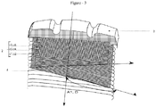
- the working layer is cut at an angle D with the circumferential direction XX '.
- the cutting angle can be different from one working layer to another.
- the inventors have observed that the spiral winding around the carcass reinforcement must first begin with an anchoring of the bevel formed by the circumferential end of the cut working layer, before starting the winding of the next layer. .
- the laying of the second layer is done with a certain delay compared to the first layer.
- the value of the offset is a compromise because it is necessary both to move away the mechanical singularities due to the cutting of the working layer, and at the same time it is necessary to limit the size of the angular sector comprising one less working layer.
- the first and second circumferential ends of each working layer of the multilayer component are offset circumferentially with respect to one another, forming between them, in an equatorial plane of the tire, an angle at least equal to 38 °.
- the value of the angle between the starting and ending circumferential ends of the same working layer is a tuning parameter of the invention which depends, in particular, on the laying radius of the multilayer component, and on the number of laps selected.
- a tuning parameter of the invention which depends, in particular, on the laying radius of the multilayer component, and on the number of laps selected.
- each working layer is circumferentially offset with respect to one another, forming between them, in an equatorial plane of the tire, an identical angle for each working layer.
- the start and end offset of each layer could thus be identical.
- the respective first circumferential ends of two consecutive working layers are circumferentially offset with respect to each other by a distance at least equal to the product of the maximum axial width of the working layers by the cotangent of l 'cutting angle of said working layer.
- Winding of the working layers must be carried out in such a way that the starting ends of two consecutive working layers, in contact with each other radially, do not coincide neither at the start nor at the end of laying. after the selected number of winding turns.
- the value of the offset of the two working layers is fixed during the debugging of the process. It depends on the cutting angle, and the axial width of the working layers. Typically, for a standard designation dimension 650/65 R38 157D, with the working layers cut at a rake angle of 30 °, the offset is a minimum of 224 mm.
- the value of the angle C1 depends on the cutting angle of the working layer, the laying radius and the width of the working layer.
- the offset measured by distance in the circumferential direction, should be at least equal to the product of the cotangent of the rake angle times the width of the working layer.
- the angle C1 can be deduced simply by knowing the laying radius of the working layer.
- the respective first circumferential ends of two consecutive working layers are circumferentially offset with respect to each other, forming between them, in an equatorial plane XZ of the tire, an identical angle C1 for each pair. two consecutive working coats.
- the offset of the circumferential ends of the layers of the stack is constant.
- the multilayer component can consist of more than two layers. And therefore, for ease of implementation, it is possible to have a constant offset between the circumferential ends of the layers, not necessarily evenly distributed.
- the first and second circumferential ends of the set of working layers are circumferentially equi-distributed.
- This embodiment is a particular case of constant offset.
- the first and second circumferential ends of all the working layers form, with respect to the circumferential direction XX ', an angle D at least equal to 30 °.
- the angle D corresponds to the cutting angle of the working layers at the start and at the end of laying.
- This oblique cut cuts through the reinforcements and the end of the working layer takes a bevel shape.
- the spiral winding of each working layer begins with an anchoring of the bevel formed by the cut.
- the oblique orientation of the cut in the working layer with respect to the circumferential direction responds to the need to avoid concentrating the ends of the reinforcements in the same meridian plane.
- the deformations of the elastomeric coating mixture are maximum in amplitude and can lead to cracking both in the meridian plane, leading to separation of the working layers in the axial direction, and also to cracking in the circumferential direction. along the reinforcements.
- the section of the diaper is oriented so as to make an angle of 30 ° with respect to the circumferential direction.
- the cutting angle of the working layers can be chosen parallel to the direction of the reinforcements.
- each working layer form an angle (A1, A2) at least equal to 10 ° and at most equal to 40 ° relative to the circumferential direction XX '.
- each working layer form an angle (A1, A2) relative to the circumferential direction XX ', which is identical for each working layer.
- One of the advantages of the invention is to be able to constitute a stack with layers whose mechanical properties are different.
- the angles that the reinforcements make with the circumferential direction are at least equal to 10 ° and more equal to 40 °, and they may be different from one layer to another. In a preferred embodiment, the angles are opposite from one layer to the next (cross stacking).
- the reinforcements of the working layers consist of textile cables.
- the reinforcements of the working layers are metal cables formed by at least one steel wire.
- a preferred embodiment of the invention is to have a spiral winding of a stack of composite layers reinforced with textile cables, but alternatively, such a stack can be made in the same way regardless of the size. nature of the reinforcements, including with metal reinforcements.
- Each working layer reinforced with textile reinforcements has a radial thickness at most equal to 1.5 mm.
- the working layers with textile reinforcements have a radial thickness of about 1.5 mm, but, with metal reinforcements, which have a larger diameter, the thickness of the layer can be significantly greater.
- the method of manufacturing the tire comprises a step of circumferential spiral winding of the multilayer component constituting the working reinforcement, radially outside the carcass reinforcement.
- the method of manufacturing the tire comprises a step of manufacturing the multilayer component by complexing the working layers upstream from the step of circumferential spiral winding of the multilayer component.
- a first step consists in the preparation of the multilayer stack which is done upstream of the circumferential spiral winding step of the multilayer component.
- the layers are cut to the desired length, then stacked successively by applying the desired offsets, and stored on a roll.
- a second step of this process consists in laying by winding the stack of working layers thus produced radially outside the carcass reinforcement.
- the method of manufacturing the tire comprises a step of manufacturing the multilayer component by complexing the working layers integrated into a step of circumferential spiral winding of the multilayer component.
- finishing assembly of the tire is fed by a device comprising as many feed rollers as there are layers in the stack.
- Each layer is stored on a roll, and the winding is done on the carcass reinforcement by lamination by managing the flow rate of each roll so as to produce the offsets of the layers.
- the invention has been more particularly studied for a radial tire for an agricultural vehicle, of dimension 650/65 R38 157D.
- this tire can carry a load of index 157 which corresponds to a mass of 4,125 kg, and can be subjected to a maximum speed of index D of 65 km / h, for a nominal pressure of 160 kPa.
- the inventors have summarized, in Table 1, the physical characteristics and the mechanical properties associated with four choices of reinforcements.
- the first three examples of reinforcements are made of HMLS polyester with a respective count of 144 tex, 220 tex, and 334 tex.
- the fourth example of reinforcement is in rayon with a count of 244 tex.
- the first three examples of reinforcements are cables obtained by twisting two yarns of filaments, the twists of which in turns per meter are indicated in the table.
- the fourth rayon reinforcement is obtained by twisting three filament yarns of 334 tex each at 330 turns per meter.
- the inventors have shown that, for proper operation of the invention, the tenacity of the polyester textile reinforcements must be greater than 60 cN / tex, and that the tenacity of the rayon reinforcements must be greater than or equal to 35 cN / tex.
- Textile cables must be strong enough to undergo all the stages of the tire manufacturing process, in particular the shaping phases, during which they undergo large deformations without being damaged.
- Thermosensitive PET textile reinforcements have a standard contraction between 0.8% and 1%.
- the twists applied to polyester yarns have an amplitude greater than 240 turns per meter and less than 270 turns per meter.
- the helix angle during the application of the torsion around the axis of the yarn is in amplitude less than or equal to 25.2 °.
- the reinforcements have adhesion properties which result in tear-off test results of between 76 Newtons per yarn and 92 Newtons per yarn for polyester cables, in rayon the tear-off force is equal to 105 Newtons per yarn. wire.
- the secant modulus of textile reinforcements at 7% deformation is in the range of 2.6 daN / mm 2 to 5.2 daN / mm 2 .
- the coating mixtures are compositions of mixtures as defined in Table 2 below: Table 2 Constituents Percent of elastoma (pc) Natural rubber 40 SBR Ref 1 (1) 25 SBR Ref 2 (2) 35 Carbon black N550 (3) 60 Oil (4) 2 Tackifying Resin (5) 5 Zinc oxide 3 Stearic acid 1.5 Antioxidant 1 (6) 1.5 Antioxidant 2 (7) 1 Sulfur 2 Sulfenamide (8) 0.5 1.: SBR Tg solution -48 ° C, % Styrene 27, % Vinyl 24, % Trans 46 2.: SBR Tg solution -54 ° C, % Styrene 26, % Vinyl 24, % Trans 47 3.: Carbon black N550 4.: MES type oil 5.: TAC OPF type tackifying resin 6.: Phenylenediamine antioxidant 7.: Antioxidant type Acetone aniline (TMQ) 8.: tert-butyl benzothiazol sulfnemide sulfenamide (TBBS)
- Density is the number of threads per decimeter (f / dm) 2.
- Nature of the reinforcements J for PET HMLS, and R for rayon 3.
- J144 / 2 means a cable made up of two strands of 144 tex each 4. Torsion applied to the strands (in turns per meter) to obtain the cable.
- Example 1 The inventors used Example 1 to produce the working reinforcement of the tire. This choice represents the best technical and economic compromise.
- the working reinforcement therefore comprises six working layers reinforced with PET textile reinforcements of the J220 / 2 type. Each working layer has a density of 87 reinforcements per decimeter.
- the coating mixture is that described in Table 2.
- the stacking of the six working layers is obtained by three spiral winding turns of the multilayer component consisting of two working layers, as shown in the figure. figure 2 , radially outside the carcass reinforcement.
- the tests making it possible to quantify the performance of a tire according to the invention relate to endurance as well as to the industrial cost price.
- the endurance result was obtained according to the test described in paragraph [022].
- the tire of the invention has a running time increased by more than 31% compared to the reference.
- the new spiral laying process has a cycle time reduced by 9% compared to the conventional layering process with a weld for each layer.
- the tire of the invention has better performance than that of the reference tire and therefore meets the initial objective of the inventors.
Landscapes
- Engineering & Computer Science (AREA)
- Mechanical Engineering (AREA)
- Tires In General (AREA)
Claims (12)
- Reifen (1) für ein landwirtschaftliches Fahrzeug, welcher eine Arbeitsbewehrung (2) umfasst, die radial innerhalb eines Laufstreifens (3) und radial außerhalb einer Karkassenbewehrung (4) angeordnet ist;- wobei die Arbeitsbewehrung (2) einen mehrschichtigen Bestandteil umfasst, der aus einem radialen Stapel aus wenigstens zwei Arbeitsschichten (21, 22) besteht;- wobei sich jede Arbeitsschicht (21, 22) des mehrschichtigen Bestandteils in Umfangsrichtung von einem ersten Umfangsende (211, 221) bis zu einem zweiten Umfangsende (212, 222) erstreckt und aus in eine Elastomermischung eingebetteten Festigkeitsträgern besteht, die zueinander parallel sind und in einem Winkel (A1, A2) bezüglich einer zu dem Laufstreifen (3) tangentialen Umfangsrichtung (XX') ausgerichtet sind;- wobei die Arbeitsbewehrung (2) aus einer spiralförmigen Umfangswicklung aus wenigstens einer Windung des mehrschichtigen Bestandteils um die Karkassenbewehrung besteht, wobei das erste und das zweite Umfangsende (211, 221; 212, 222) jeder Arbeitsschicht (21, 22) des mehrschichtigen Bestandteils in Umfangsrichtung um einen Winkel (B1, B2) zueinander versetzt sind;- wobei die jeweiligen ersten Umfangsenden (211, 221) zweier aufeinander folgender Arbeitsschichten (21, 22) des mehrschichtigen Bestandteils in Umfangsrichtung um einen Winkel C1 zueinander versetzt sind,
dadurch gekennzeichnet, dass die ersten und zweiten Umfangsenden (211, 221; 212, 222) der Anordnung der Arbeitsschichten (21, 22) in der Umfangsrichtung auf Positionen verteilt sind, die auf einer Windung gleichmäßig verteilt sind. - Reifen nach Anspruch 1, wobei das erste und das zweite Umfangsende (211, 221; 212, 222) jeder Arbeitsschicht (21, 22) des mehrschichtigen Bestandteils in Umfangsrichtung um einen Winkel (B1, B2) zueinander versetzt sind, der mindestens 38° beträgt.
- Reifen nach einem der Ansprüche 1 oder 2, wobei das erste und das zweite Umfangsende (211, 221; 212, 222) jeder Arbeitsschicht (21, 22) in Umfangsrichtung um einen Winkel (B1, B2) zueinander versetzt sind, der für alle Arbeitsschichten (21, 22) identisch ist.
- Reifen nach einem der Ansprüche 1 bis 3, wobei die jeweiligen ersten Umfangsenden (211, 221) zweier aufeinander folgender Arbeitsschichten (21, 22) in Umfangsrichtung um einen Abstand zueinander versetzt sind, der wenigstens gleich dem Produkt der maximalen axialen Breite der Arbeitsschichten mit dem Kotangens des Schnittwinkels der Arbeitsschicht ist.
- Reifen nach einem der Ansprüche 1 bis 4, wobei die jeweiligen ersten Umfangsenden (211, 221) zweier aufeinander folgender Arbeitsschichten (21, 22) in Umfangsrichtung um einen Winkel (C1) zueinander versetzt sind, der für alle Paare von zwei aufeinander folgenden Arbeitsschichten (21, 22) identisch ist.
- Reifen nach einem der Ansprüche 1 bis 5, wobei die ersten und zweiten Umfangsenden (211, 221; 212, 222) der Anordnung der Arbeitsschichten (21, 22) bezüglich der Umfangsrichtung (XX') einen Winkel (D) bilden, der mindestens 30° beträgt.
- Reifen nach einem der Ansprüche 1 bis 6, wobei die Festigkeitsträger jeder Arbeitsschicht (21, 22) bezüglich der Umfangsrichtung (XX') einen Winkel (A1, A2) bilden, der mindestens 10° und höchstens 40° beträgt.
- Reifen nach einem der Ansprüche 1 bis 7, wobei die Festigkeitsträger jeder Arbeitsschicht (21, 22) bezüglich der Umfangsrichtung (XX') einen Winkel (A1, A2) bilden, der für alle Arbeitsschichten (21, 22) identisch ist.
- Reifen nach einem der Ansprüche 1 bis 8, wobei die jeweiligen Festigkeitsträger zweier aufeinander folgender (21, 22) Arbeitsschichten (21, 22) sich von einer Schicht zur anderen überkreuzen.
- Reifen nach einem der Ansprüche 1 bis 9, wobei die Festigkeitsträger von Arbeitsschichten (21, 22) aus textilen Filamentgarnen bestehen.
- Reifen nach einem der Ansprüche 1 bis 9, wobei die Festigkeitsträger von Arbeitsschichten (21, 22) Metallseile sind, die aus wenigstens einem Stahldraht bestehen.
- Reifen nach einem der Ansprüche 1 bis 10, wobei jede mit textilen Festigkeitsträgern verstärkte Arbeitsschicht (21, 22) eine radiale Dicke aufweist, die höchstens 1,5 mm beträgt.
Applications Claiming Priority (2)
| Application Number | Priority Date | Filing Date | Title |
|---|---|---|---|
| FR1759634 | 2017-10-13 | ||
| PCT/FR2018/052402 WO2019073143A1 (fr) | 2017-10-13 | 2018-10-01 | Armature de sommet d'un pneumatique pour vehicule agricole de type tracteur |
Publications (2)
| Publication Number | Publication Date |
|---|---|
| EP3694702A1 EP3694702A1 (de) | 2020-08-19 |
| EP3694702B1 true EP3694702B1 (de) | 2021-12-01 |
Family
ID=60627847
Family Applications (1)
| Application Number | Title | Priority Date | Filing Date |
|---|---|---|---|
| EP18792976.5A Active EP3694702B1 (de) | 2017-10-13 | 2018-10-01 | Kronenverstärkung für einen reifen eines traktorartigen landwirtschaftlichen fahrzeugs |
Country Status (3)
| Country | Link |
|---|---|
| US (1) | US11697309B2 (de) |
| EP (1) | EP3694702B1 (de) |
| WO (1) | WO2019073143A1 (de) |
Families Citing this family (3)
| Publication number | Priority date | Publication date | Assignee | Title |
|---|---|---|---|---|
| FR3113867B1 (fr) * | 2020-09-04 | 2022-08-12 | Michelin & Cie | Pneumatique pour véhicule agricole de forte puissance |
| FR3113868B1 (fr) * | 2020-09-04 | 2022-08-12 | Michelin & Cie | Pneumatique pour véhicule agricole à sommet allégé |
| FR3113866B1 (fr) * | 2020-09-04 | 2022-08-12 | Michelin & Cie | Pneumatique pour véhicule agricole de grande dimension |
Family Cites Families (7)
| Publication number | Priority date | Publication date | Assignee | Title |
|---|---|---|---|---|
| AT312441B (de) | 1970-02-20 | 1973-12-27 | Semperit Ag | Luftreifen |
| EP1272363A1 (de) * | 2000-04-11 | 2003-01-08 | AlliedSignal Inc. | Verbund, der organische fasern mit einem niedrigen drehungskoeffizient enthält und einem verbesserten kompressionsmodul |
| US9637844B2 (en) | 2011-03-24 | 2017-05-02 | Bridgestone Corporation | Steel cord for rubber article reinforcement and pneumatic radial tire using same |
| FR2986740B1 (fr) * | 2012-02-09 | 2014-03-21 | Michelin & Cie | Pneumatique a structure de ceinture allegee |
| JP5756451B2 (ja) * | 2012-12-11 | 2015-07-29 | 住友ゴム工業株式会社 | 空気入りタイヤ |
| JP6450112B2 (ja) | 2014-08-15 | 2019-01-09 | 株式会社ブリヂストン | 空気入りタイヤ |
| JP6720539B2 (ja) | 2016-01-13 | 2020-07-08 | 住友ゴム工業株式会社 | 空気入りタイヤ |
-
2018
- 2018-10-01 WO PCT/FR2018/052402 patent/WO2019073143A1/fr unknown
- 2018-10-01 EP EP18792976.5A patent/EP3694702B1/de active Active
- 2018-10-01 US US16/755,691 patent/US11697309B2/en active Active
Also Published As
| Publication number | Publication date |
|---|---|
| US20200290404A1 (en) | 2020-09-17 |
| EP3694702A1 (de) | 2020-08-19 |
| WO2019073143A1 (fr) | 2019-04-18 |
| US11697309B2 (en) | 2023-07-11 |
| BR112020006534A2 (pt) | 2020-09-29 |
Similar Documents
| Publication | Publication Date | Title |
|---|---|---|
| EP2906434B1 (de) | Notlaufreifen mit einer hybridkarkassenlage | |
| EP2812194B1 (de) | Radialreifen mit leichterer gürtelstruktur | |
| EP3694702B1 (de) | Kronenverstärkung für einen reifen eines traktorartigen landwirtschaftlichen fahrzeugs | |
| EP3027424B1 (de) | Radialreifen mit leichtgewichtiger gürtelstruktur | |
| EP3515727B1 (de) | Elastomerkomposit und reifen enthaltend ein solches komposit | |
| FR3009238A1 (fr) | Pneu radial a structure de ceinture allegee | |
| WO2020021006A1 (fr) | Câble ouvert a haute compressibilite | |
| WO2018051032A1 (fr) | Élément de renfort, composite d'élastomère et pneumatique comprenant cet élément de renfort | |
| EP3826863A1 (de) | Metallseile mit bi-modul | |
| EP2237975B1 (de) | Leichter radialreifen | |
| WO2015124758A1 (fr) | Armature de sommet de pneumatique pour avion | |
| WO2021014096A1 (fr) | Cable ouvert renforcant a haute compressibilite | |
| EP3131762B1 (de) | Gürtelverstärkung für einen flugzeugreifen | |
| EP3463839B1 (de) | Gerade lage und winklige lage aus metallischen monofilamenten | |
| EP3086954B1 (de) | Reifen mit einem trikot | |
| EP2234820B1 (de) | Leichter reifen mit einer laufflächenschicht radial an der innenseite der karkassenstruktur | |
| EP2150423B1 (de) | Reifen für fahrzeug mit verstärkungen in den seitenwänden | |
| EP4058629B1 (de) | Zweischichtige metallische kabel, die eine ummantelte innere schicht und eine verbesserte leistung aufweisen | |
| EP3880492B1 (de) | Reifen für zweiradfahrzeug mit einer hybriden umreifungsverstärkung | |
| FR2999983A1 (fr) | Pneumatique a sommet dissymetrique | |
| WO2024017580A1 (fr) | Tissu pour pneumatique comprenant des éléments de renfort comprenant un assemblage constitué de deux brins multifilamentaires de polyamide 5,6 | |
| EP3131761A1 (de) | Gürtelverstärkung für einen flugzeugreifen |
Legal Events
| Date | Code | Title | Description |
|---|---|---|---|
| STAA | Information on the status of an ep patent application or granted ep patent |
Free format text: STATUS: UNKNOWN |
|
| STAA | Information on the status of an ep patent application or granted ep patent |
Free format text: STATUS: THE INTERNATIONAL PUBLICATION HAS BEEN MADE |
|
| PUAI | Public reference made under article 153(3) epc to a published international application that has entered the european phase |
Free format text: ORIGINAL CODE: 0009012 |
|
| STAA | Information on the status of an ep patent application or granted ep patent |
Free format text: STATUS: REQUEST FOR EXAMINATION WAS MADE |
|
| 17P | Request for examination filed |
Effective date: 20200513 |
|
| AK | Designated contracting states |
Kind code of ref document: A1 Designated state(s): AL AT BE BG CH CY CZ DE DK EE ES FI FR GB GR HR HU IE IS IT LI LT LU LV MC MK MT NL NO PL PT RO RS SE SI SK SM TR |
|
| AX | Request for extension of the european patent |
Extension state: BA ME |
|
| DAV | Request for validation of the european patent (deleted) | ||
| DAX | Request for extension of the european patent (deleted) | ||
| REG | Reference to a national code |
Ref country code: DE Ref legal event code: R079 Ref document number: 602018027602 Country of ref document: DE Free format text: PREVIOUS MAIN CLASS: B29D0030160000 Ipc: B60C0009200000 |
|
| RIC1 | Information provided on ipc code assigned before grant |
Ipc: B29D 30/70 20060101ALI20210326BHEP Ipc: B29D 30/30 20060101ALI20210326BHEP Ipc: B29D 30/16 20060101ALI20210326BHEP Ipc: B60C 9/20 20060101AFI20210326BHEP |
|
| GRAP | Despatch of communication of intention to grant a patent |
Free format text: ORIGINAL CODE: EPIDOSNIGR1 |
|
| STAA | Information on the status of an ep patent application or granted ep patent |
Free format text: STATUS: GRANT OF PATENT IS INTENDED |
|
| INTG | Intention to grant announced |
Effective date: 20210611 |
|
| GRAS | Grant fee paid |
Free format text: ORIGINAL CODE: EPIDOSNIGR3 |
|
| GRAA | (expected) grant |
Free format text: ORIGINAL CODE: 0009210 |
|
| STAA | Information on the status of an ep patent application or granted ep patent |
Free format text: STATUS: THE PATENT HAS BEEN GRANTED |
|
| AK | Designated contracting states |
Kind code of ref document: B1 Designated state(s): AL AT BE BG CH CY CZ DE DK EE ES FI FR GB GR HR HU IE IS IT LI LT LU LV MC MK MT NL NO PL PT RO RS SE SI SK SM TR |
|
| REG | Reference to a national code |
Ref country code: GB Ref legal event code: FG4D Free format text: NOT ENGLISH |
|
| REG | Reference to a national code |
Ref country code: AT Ref legal event code: REF Ref document number: 1451411 Country of ref document: AT Kind code of ref document: T Effective date: 20211215 Ref country code: CH Ref legal event code: EP |
|
| REG | Reference to a national code |
Ref country code: IE Ref legal event code: FG4D Free format text: LANGUAGE OF EP DOCUMENT: FRENCH |
|
| REG | Reference to a national code |
Ref country code: DE Ref legal event code: R096 Ref document number: 602018027602 Country of ref document: DE |
|
| REG | Reference to a national code |
Ref country code: LT Ref legal event code: MG9D |
|
| REG | Reference to a national code |
Ref country code: NL Ref legal event code: MP Effective date: 20211201 |
|
| REG | Reference to a national code |
Ref country code: AT Ref legal event code: MK05 Ref document number: 1451411 Country of ref document: AT Kind code of ref document: T Effective date: 20211201 |
|
| PG25 | Lapsed in a contracting state [announced via postgrant information from national office to epo] |
Ref country code: RS Free format text: LAPSE BECAUSE OF FAILURE TO SUBMIT A TRANSLATION OF THE DESCRIPTION OR TO PAY THE FEE WITHIN THE PRESCRIBED TIME-LIMIT Effective date: 20211201 Ref country code: LT Free format text: LAPSE BECAUSE OF FAILURE TO SUBMIT A TRANSLATION OF THE DESCRIPTION OR TO PAY THE FEE WITHIN THE PRESCRIBED TIME-LIMIT Effective date: 20211201 Ref country code: FI Free format text: LAPSE BECAUSE OF FAILURE TO SUBMIT A TRANSLATION OF THE DESCRIPTION OR TO PAY THE FEE WITHIN THE PRESCRIBED TIME-LIMIT Effective date: 20211201 Ref country code: BG Free format text: LAPSE BECAUSE OF FAILURE TO SUBMIT A TRANSLATION OF THE DESCRIPTION OR TO PAY THE FEE WITHIN THE PRESCRIBED TIME-LIMIT Effective date: 20220301 Ref country code: AT Free format text: LAPSE BECAUSE OF FAILURE TO SUBMIT A TRANSLATION OF THE DESCRIPTION OR TO PAY THE FEE WITHIN THE PRESCRIBED TIME-LIMIT Effective date: 20211201 |
|
| PG25 | Lapsed in a contracting state [announced via postgrant information from national office to epo] |
Ref country code: SE Free format text: LAPSE BECAUSE OF FAILURE TO SUBMIT A TRANSLATION OF THE DESCRIPTION OR TO PAY THE FEE WITHIN THE PRESCRIBED TIME-LIMIT Effective date: 20211201 Ref country code: PL Free format text: LAPSE BECAUSE OF FAILURE TO SUBMIT A TRANSLATION OF THE DESCRIPTION OR TO PAY THE FEE WITHIN THE PRESCRIBED TIME-LIMIT Effective date: 20211201 Ref country code: NO Free format text: LAPSE BECAUSE OF FAILURE TO SUBMIT A TRANSLATION OF THE DESCRIPTION OR TO PAY THE FEE WITHIN THE PRESCRIBED TIME-LIMIT Effective date: 20220301 Ref country code: LV Free format text: LAPSE BECAUSE OF FAILURE TO SUBMIT A TRANSLATION OF THE DESCRIPTION OR TO PAY THE FEE WITHIN THE PRESCRIBED TIME-LIMIT Effective date: 20211201 Ref country code: HR Free format text: LAPSE BECAUSE OF FAILURE TO SUBMIT A TRANSLATION OF THE DESCRIPTION OR TO PAY THE FEE WITHIN THE PRESCRIBED TIME-LIMIT Effective date: 20211201 Ref country code: GR Free format text: LAPSE BECAUSE OF FAILURE TO SUBMIT A TRANSLATION OF THE DESCRIPTION OR TO PAY THE FEE WITHIN THE PRESCRIBED TIME-LIMIT Effective date: 20220302 |
|
| PG25 | Lapsed in a contracting state [announced via postgrant information from national office to epo] |
Ref country code: NL Free format text: LAPSE BECAUSE OF FAILURE TO SUBMIT A TRANSLATION OF THE DESCRIPTION OR TO PAY THE FEE WITHIN THE PRESCRIBED TIME-LIMIT Effective date: 20211201 |
|
| PG25 | Lapsed in a contracting state [announced via postgrant information from national office to epo] |
Ref country code: SM Free format text: LAPSE BECAUSE OF FAILURE TO SUBMIT A TRANSLATION OF THE DESCRIPTION OR TO PAY THE FEE WITHIN THE PRESCRIBED TIME-LIMIT Effective date: 20211201 Ref country code: SK Free format text: LAPSE BECAUSE OF FAILURE TO SUBMIT A TRANSLATION OF THE DESCRIPTION OR TO PAY THE FEE WITHIN THE PRESCRIBED TIME-LIMIT Effective date: 20211201 Ref country code: RO Free format text: LAPSE BECAUSE OF FAILURE TO SUBMIT A TRANSLATION OF THE DESCRIPTION OR TO PAY THE FEE WITHIN THE PRESCRIBED TIME-LIMIT Effective date: 20211201 Ref country code: PT Free format text: LAPSE BECAUSE OF FAILURE TO SUBMIT A TRANSLATION OF THE DESCRIPTION OR TO PAY THE FEE WITHIN THE PRESCRIBED TIME-LIMIT Effective date: 20220401 Ref country code: ES Free format text: LAPSE BECAUSE OF FAILURE TO SUBMIT A TRANSLATION OF THE DESCRIPTION OR TO PAY THE FEE WITHIN THE PRESCRIBED TIME-LIMIT Effective date: 20211201 Ref country code: EE Free format text: LAPSE BECAUSE OF FAILURE TO SUBMIT A TRANSLATION OF THE DESCRIPTION OR TO PAY THE FEE WITHIN THE PRESCRIBED TIME-LIMIT Effective date: 20211201 Ref country code: CZ Free format text: LAPSE BECAUSE OF FAILURE TO SUBMIT A TRANSLATION OF THE DESCRIPTION OR TO PAY THE FEE WITHIN THE PRESCRIBED TIME-LIMIT Effective date: 20211201 |
|
| REG | Reference to a national code |
Ref country code: DE Ref legal event code: R097 Ref document number: 602018027602 Country of ref document: DE |
|
| PG25 | Lapsed in a contracting state [announced via postgrant information from national office to epo] |
Ref country code: IS Free format text: LAPSE BECAUSE OF FAILURE TO SUBMIT A TRANSLATION OF THE DESCRIPTION OR TO PAY THE FEE WITHIN THE PRESCRIBED TIME-LIMIT Effective date: 20220401 |
|
| PLBE | No opposition filed within time limit |
Free format text: ORIGINAL CODE: 0009261 |
|
| STAA | Information on the status of an ep patent application or granted ep patent |
Free format text: STATUS: NO OPPOSITION FILED WITHIN TIME LIMIT |
|
| PG25 | Lapsed in a contracting state [announced via postgrant information from national office to epo] |
Ref country code: DK Free format text: LAPSE BECAUSE OF FAILURE TO SUBMIT A TRANSLATION OF THE DESCRIPTION OR TO PAY THE FEE WITHIN THE PRESCRIBED TIME-LIMIT Effective date: 20211201 Ref country code: AL Free format text: LAPSE BECAUSE OF FAILURE TO SUBMIT A TRANSLATION OF THE DESCRIPTION OR TO PAY THE FEE WITHIN THE PRESCRIBED TIME-LIMIT Effective date: 20211201 |
|
| 26N | No opposition filed |
Effective date: 20220902 |
|
| PG25 | Lapsed in a contracting state [announced via postgrant information from national office to epo] |
Ref country code: SI Free format text: LAPSE BECAUSE OF FAILURE TO SUBMIT A TRANSLATION OF THE DESCRIPTION OR TO PAY THE FEE WITHIN THE PRESCRIBED TIME-LIMIT Effective date: 20211201 |
|
| PGFP | Annual fee paid to national office [announced via postgrant information from national office to epo] |
Ref country code: FR Payment date: 20221031 Year of fee payment: 5 |
|
| PGFP | Annual fee paid to national office [announced via postgrant information from national office to epo] |
Ref country code: DE Payment date: 20221019 Year of fee payment: 5 |
|
| PG25 | Lapsed in a contracting state [announced via postgrant information from national office to epo] |
Ref country code: MC Free format text: LAPSE BECAUSE OF FAILURE TO SUBMIT A TRANSLATION OF THE DESCRIPTION OR TO PAY THE FEE WITHIN THE PRESCRIBED TIME-LIMIT Effective date: 20211201 Ref country code: IT Free format text: LAPSE BECAUSE OF FAILURE TO SUBMIT A TRANSLATION OF THE DESCRIPTION OR TO PAY THE FEE WITHIN THE PRESCRIBED TIME-LIMIT Effective date: 20211201 |
|
| REG | Reference to a national code |
Ref country code: CH Ref legal event code: PL |
|
| REG | Reference to a national code |
Ref country code: BE Ref legal event code: MM Effective date: 20221031 |
|
| GBPC | Gb: european patent ceased through non-payment of renewal fee |
Effective date: 20221001 |
|
| PG25 | Lapsed in a contracting state [announced via postgrant information from national office to epo] |
Ref country code: LU Free format text: LAPSE BECAUSE OF NON-PAYMENT OF DUE FEES Effective date: 20221001 |
|
| PG25 | Lapsed in a contracting state [announced via postgrant information from national office to epo] |
Ref country code: LI Free format text: LAPSE BECAUSE OF NON-PAYMENT OF DUE FEES Effective date: 20221031 Ref country code: CH Free format text: LAPSE BECAUSE OF NON-PAYMENT OF DUE FEES Effective date: 20221031 |
|
| PG25 | Lapsed in a contracting state [announced via postgrant information from national office to epo] |
Ref country code: BE Free format text: LAPSE BECAUSE OF NON-PAYMENT OF DUE FEES Effective date: 20221031 |
|
| PG25 | Lapsed in a contracting state [announced via postgrant information from national office to epo] |
Ref country code: IE Free format text: LAPSE BECAUSE OF NON-PAYMENT OF DUE FEES Effective date: 20221001 Ref country code: GB Free format text: LAPSE BECAUSE OF NON-PAYMENT OF DUE FEES Effective date: 20221001 |
|
| PG25 | Lapsed in a contracting state [announced via postgrant information from national office to epo] |
Ref country code: CY Free format text: LAPSE BECAUSE OF FAILURE TO SUBMIT A TRANSLATION OF THE DESCRIPTION OR TO PAY THE FEE WITHIN THE PRESCRIBED TIME-LIMIT Effective date: 20211201 |
|
| REG | Reference to a national code |
Ref country code: DE Ref legal event code: R119 Ref document number: 602018027602 Country of ref document: DE |
|
| PG25 | Lapsed in a contracting state [announced via postgrant information from national office to epo] |
Ref country code: MK Free format text: LAPSE BECAUSE OF FAILURE TO SUBMIT A TRANSLATION OF THE DESCRIPTION OR TO PAY THE FEE WITHIN THE PRESCRIBED TIME-LIMIT Effective date: 20211201 Ref country code: HU Free format text: LAPSE BECAUSE OF FAILURE TO SUBMIT A TRANSLATION OF THE DESCRIPTION OR TO PAY THE FEE WITHIN THE PRESCRIBED TIME-LIMIT; INVALID AB INITIO Effective date: 20181001 |
|
| PG25 | Lapsed in a contracting state [announced via postgrant information from national office to epo] |
Ref country code: FR Free format text: LAPSE BECAUSE OF NON-PAYMENT OF DUE FEES Effective date: 20231031 Ref country code: DE Free format text: LAPSE BECAUSE OF NON-PAYMENT OF DUE FEES Effective date: 20240501 |