EP3694645B1 - Device having a first and a second chamber for receiving a body fluid - Google Patents
Device having a first and a second chamber for receiving a body fluid Download PDFInfo
- Publication number
- EP3694645B1 EP3694645B1 EP18793575.4A EP18793575A EP3694645B1 EP 3694645 B1 EP3694645 B1 EP 3694645B1 EP 18793575 A EP18793575 A EP 18793575A EP 3694645 B1 EP3694645 B1 EP 3694645B1
- Authority
- EP
- European Patent Office
- Prior art keywords
- chamber
- body fluid
- guide
- wall
- designed
- Prior art date
- Legal status (The legal status is an assumption and is not a legal conclusion. Google has not performed a legal analysis and makes no representation as to the accuracy of the status listed.)
- Active
Links
- 210000001124 body fluid Anatomy 0.000 title claims description 74
- 239000010839 body fluid Substances 0.000 title claims description 74
- 238000005119 centrifugation Methods 0.000 claims description 52
- 230000004888 barrier function Effects 0.000 claims description 36
- 238000012546 transfer Methods 0.000 claims description 21
- 238000011049 filling Methods 0.000 claims description 18
- 238000007789 sealing Methods 0.000 claims description 12
- 239000000126 substance Substances 0.000 claims description 11
- 210000004369 blood Anatomy 0.000 description 39
- 239000008280 blood Substances 0.000 description 39
- 238000000034 method Methods 0.000 description 25
- 239000012530 fluid Substances 0.000 description 12
- 239000000306 component Substances 0.000 description 11
- 238000011534 incubation Methods 0.000 description 11
- 230000000903 blocking effect Effects 0.000 description 10
- 238000000926 separation method Methods 0.000 description 10
- 238000006073 displacement reaction Methods 0.000 description 8
- 230000008569 process Effects 0.000 description 7
- 108090000623 proteins and genes Proteins 0.000 description 7
- 229940088623 biologically active substance Drugs 0.000 description 6
- 238000011109 contamination Methods 0.000 description 6
- 239000007788 liquid Substances 0.000 description 6
- 210000002381 plasma Anatomy 0.000 description 6
- 102000004169 proteins and genes Human genes 0.000 description 6
- 239000000654 additive Substances 0.000 description 5
- 241001465754 Metazoa Species 0.000 description 4
- 230000015572 biosynthetic process Effects 0.000 description 4
- 239000012503 blood component Substances 0.000 description 4
- 230000008859 change Effects 0.000 description 4
- 238000013461 design Methods 0.000 description 4
- 238000012545 processing Methods 0.000 description 4
- 238000003860 storage Methods 0.000 description 4
- 101001076407 Homo sapiens Interleukin-1 receptor antagonist protein Proteins 0.000 description 3
- 229940119178 Interleukin 1 receptor antagonist Drugs 0.000 description 3
- 102000051628 Interleukin-1 receptor antagonist Human genes 0.000 description 3
- 239000003407 interleukin 1 receptor blocking agent Substances 0.000 description 3
- 239000012528 membrane Substances 0.000 description 3
- 239000000565 sealant Substances 0.000 description 3
- VYPSYNLAJGMNEJ-UHFFFAOYSA-N silicon dioxide Inorganic materials O=[Si]=O VYPSYNLAJGMNEJ-UHFFFAOYSA-N 0.000 description 3
- 239000003146 anticoagulant agent Substances 0.000 description 2
- 229940127219 anticoagulant drug Drugs 0.000 description 2
- 230000000035 biogenic effect Effects 0.000 description 2
- 238000010241 blood sampling Methods 0.000 description 2
- 239000000470 constituent Substances 0.000 description 2
- 230000000694 effects Effects 0.000 description 2
- 229920001971 elastomer Polymers 0.000 description 2
- 239000000806 elastomer Substances 0.000 description 2
- 239000011521 glass Substances 0.000 description 2
- 230000001939 inductive effect Effects 0.000 description 2
- 230000036512 infertility Effects 0.000 description 2
- 238000012432 intermediate storage Methods 0.000 description 2
- 238000004519 manufacturing process Methods 0.000 description 2
- 239000011049 pearl Substances 0.000 description 2
- 239000000843 powder Substances 0.000 description 2
- 210000002966 serum Anatomy 0.000 description 2
- 239000007787 solid Substances 0.000 description 2
- FUFLCEKSBBHCMO-UHFFFAOYSA-N 11-dehydrocorticosterone Natural products O=C1CCC2(C)C3C(=O)CC(C)(C(CC4)C(=O)CO)C4C3CCC2=C1 FUFLCEKSBBHCMO-UHFFFAOYSA-N 0.000 description 1
- 241000272525 Anas platyrhynchos Species 0.000 description 1
- KRKNYBCHXYNGOX-UHFFFAOYSA-K Citrate Chemical compound [O-]C(=O)CC(O)(CC([O-])=O)C([O-])=O KRKNYBCHXYNGOX-UHFFFAOYSA-K 0.000 description 1
- 102000008186 Collagen Human genes 0.000 description 1
- 108010035532 Collagen Proteins 0.000 description 1
- MFYSYFVPBJMHGN-ZPOLXVRWSA-N Cortisone Chemical compound O=C1CC[C@]2(C)[C@H]3C(=O)C[C@](C)([C@@](CC4)(O)C(=O)CO)[C@@H]4[C@@H]3CCC2=C1 MFYSYFVPBJMHGN-ZPOLXVRWSA-N 0.000 description 1
- MFYSYFVPBJMHGN-UHFFFAOYSA-N Cortisone Natural products O=C1CCC2(C)C3C(=O)CC(C)(C(CC4)(O)C(=O)CO)C4C3CCC2=C1 MFYSYFVPBJMHGN-UHFFFAOYSA-N 0.000 description 1
- KCXVZYZYPLLWCC-UHFFFAOYSA-N EDTA Chemical compound OC(=O)CN(CC(O)=O)CCN(CC(O)=O)CC(O)=O KCXVZYZYPLLWCC-UHFFFAOYSA-N 0.000 description 1
- HTTJABKRGRZYRN-UHFFFAOYSA-N Heparin Chemical compound OC1C(NC(=O)C)C(O)OC(COS(O)(=O)=O)C1OC1C(OS(O)(=O)=O)C(O)C(OC2C(C(OS(O)(=O)=O)C(OC3C(C(O)C(O)C(O3)C(O)=O)OS(O)(=O)=O)C(CO)O2)NS(O)(=O)=O)C(C(O)=O)O1 HTTJABKRGRZYRN-UHFFFAOYSA-N 0.000 description 1
- 239000006004 Quartz sand Substances 0.000 description 1
- 230000001133 acceleration Effects 0.000 description 1
- 238000009825 accumulation Methods 0.000 description 1
- 239000013543 active substance Substances 0.000 description 1
- 229920000615 alginic acid Polymers 0.000 description 1
- 235000010443 alginic acid Nutrition 0.000 description 1
- 239000002981 blocking agent Substances 0.000 description 1
- 210000001185 bone marrow Anatomy 0.000 description 1
- 239000002775 capsule Substances 0.000 description 1
- 210000004027 cell Anatomy 0.000 description 1
- 229920002678 cellulose Polymers 0.000 description 1
- 239000001913 cellulose Substances 0.000 description 1
- 239000003795 chemical substances by application Substances 0.000 description 1
- 238000004587 chromatography analysis Methods 0.000 description 1
- 239000011248 coating agent Substances 0.000 description 1
- 238000000576 coating method Methods 0.000 description 1
- 229920001436 collagen Polymers 0.000 description 1
- 238000004891 communication Methods 0.000 description 1
- 230000000295 complement effect Effects 0.000 description 1
- 229960004544 cortisone Drugs 0.000 description 1
- 239000010431 corundum Substances 0.000 description 1
- 229910052593 corundum Inorganic materials 0.000 description 1
- 230000001419 dependent effect Effects 0.000 description 1
- 239000008187 granular material Substances 0.000 description 1
- 229960002897 heparin Drugs 0.000 description 1
- 229920000669 heparin Polymers 0.000 description 1
- 230000006872 improvement Effects 0.000 description 1
- 150000002500 ions Chemical class 0.000 description 1
- 238000002955 isolation Methods 0.000 description 1
- 239000003446 ligand Substances 0.000 description 1
- 210000004880 lymph fluid Anatomy 0.000 description 1
- 239000000463 material Substances 0.000 description 1
- 230000004060 metabolic process Effects 0.000 description 1
- 239000002207 metabolite Substances 0.000 description 1
- 229910052751 metal Inorganic materials 0.000 description 1
- 239000002184 metal Substances 0.000 description 1
- 150000002739 metals Chemical class 0.000 description 1
- 238000012986 modification Methods 0.000 description 1
- 230000004048 modification Effects 0.000 description 1
- 102000039446 nucleic acids Human genes 0.000 description 1
- 108020004707 nucleic acids Proteins 0.000 description 1
- 150000007523 nucleic acids Chemical class 0.000 description 1
- 150000002894 organic compounds Chemical class 0.000 description 1
- 230000000149 penetrating effect Effects 0.000 description 1
- 230000035479 physiological effects, processes and functions Effects 0.000 description 1
- 229920000642 polymer Polymers 0.000 description 1
- 239000011148 porous material Substances 0.000 description 1
- 238000002360 preparation method Methods 0.000 description 1
- 239000010453 quartz Substances 0.000 description 1
- 210000003296 saliva Anatomy 0.000 description 1
- 239000004576 sand Substances 0.000 description 1
- 239000002594 sorbent Substances 0.000 description 1
- -1 spheres Substances 0.000 description 1
- 210000002700 urine Anatomy 0.000 description 1
Images


Classifications
-
- B—PERFORMING OPERATIONS; TRANSPORTING
- B01—PHYSICAL OR CHEMICAL PROCESSES OR APPARATUS IN GENERAL
- B01L—CHEMICAL OR PHYSICAL LABORATORY APPARATUS FOR GENERAL USE
- B01L3/00—Containers or dishes for laboratory use, e.g. laboratory glassware; Droppers
- B01L3/50—Containers for the purpose of retaining a material to be analysed, e.g. test tubes
- B01L3/502—Containers for the purpose of retaining a material to be analysed, e.g. test tubes with fluid transport, e.g. in multi-compartment structures
- B01L3/5021—Test tubes specially adapted for centrifugation purposes
-
- A—HUMAN NECESSITIES
- A61—MEDICAL OR VETERINARY SCIENCE; HYGIENE
- A61M—DEVICES FOR INTRODUCING MEDIA INTO, OR ONTO, THE BODY; DEVICES FOR TRANSDUCING BODY MEDIA OR FOR TAKING MEDIA FROM THE BODY; DEVICES FOR PRODUCING OR ENDING SLEEP OR STUPOR
- A61M1/00—Suction or pumping devices for medical purposes; Devices for carrying-off, for treatment of, or for carrying-over, body-liquids; Drainage systems
- A61M1/02—Blood transfusion apparatus
- A61M1/029—Separating blood components present in distinct layers in a container, not otherwise provided for
-
- B—PERFORMING OPERATIONS; TRANSPORTING
- B01—PHYSICAL OR CHEMICAL PROCESSES OR APPARATUS IN GENERAL
- B01L—CHEMICAL OR PHYSICAL LABORATORY APPARATUS FOR GENERAL USE
- B01L3/00—Containers or dishes for laboratory use, e.g. laboratory glassware; Droppers
- B01L3/50—Containers for the purpose of retaining a material to be analysed, e.g. test tubes
- B01L3/502—Containers for the purpose of retaining a material to be analysed, e.g. test tubes with fluid transport, e.g. in multi-compartment structures
-
- A—HUMAN NECESSITIES
- A61—MEDICAL OR VETERINARY SCIENCE; HYGIENE
- A61M—DEVICES FOR INTRODUCING MEDIA INTO, OR ONTO, THE BODY; DEVICES FOR TRANSDUCING BODY MEDIA OR FOR TAKING MEDIA FROM THE BODY; DEVICES FOR PRODUCING OR ENDING SLEEP OR STUPOR
- A61M1/00—Suction or pumping devices for medical purposes; Devices for carrying-off, for treatment of, or for carrying-over, body-liquids; Drainage systems
- A61M1/36—Other treatment of blood in a by-pass of the natural circulatory system, e.g. temperature adaptation, irradiation ; Extra-corporeal blood circuits
- A61M1/3693—Other treatment of blood in a by-pass of the natural circulatory system, e.g. temperature adaptation, irradiation ; Extra-corporeal blood circuits using separation based on different densities of components, e.g. centrifuging
-
- B—PERFORMING OPERATIONS; TRANSPORTING
- B01—PHYSICAL OR CHEMICAL PROCESSES OR APPARATUS IN GENERAL
- B01L—CHEMICAL OR PHYSICAL LABORATORY APPARATUS FOR GENERAL USE
- B01L2200/00—Solutions for specific problems relating to chemical or physical laboratory apparatus
- B01L2200/02—Adapting objects or devices to another
- B01L2200/026—Fluid interfacing between devices or objects, e.g. connectors, inlet details
-
- B—PERFORMING OPERATIONS; TRANSPORTING
- B01—PHYSICAL OR CHEMICAL PROCESSES OR APPARATUS IN GENERAL
- B01L—CHEMICAL OR PHYSICAL LABORATORY APPARATUS FOR GENERAL USE
- B01L2200/00—Solutions for specific problems relating to chemical or physical laboratory apparatus
- B01L2200/06—Fluid handling related problems
- B01L2200/0621—Control of the sequence of chambers filled or emptied
-
- B—PERFORMING OPERATIONS; TRANSPORTING
- B01—PHYSICAL OR CHEMICAL PROCESSES OR APPARATUS IN GENERAL
- B01L—CHEMICAL OR PHYSICAL LABORATORY APPARATUS FOR GENERAL USE
- B01L2300/00—Additional constructional details
- B01L2300/04—Closures and closing means
- B01L2300/041—Connecting closures to device or container
- B01L2300/044—Connecting closures to device or container pierceable, e.g. films, membranes
-
- B—PERFORMING OPERATIONS; TRANSPORTING
- B01—PHYSICAL OR CHEMICAL PROCESSES OR APPARATUS IN GENERAL
- B01L—CHEMICAL OR PHYSICAL LABORATORY APPARATUS FOR GENERAL USE
- B01L2300/00—Additional constructional details
- B01L2300/04—Closures and closing means
- B01L2300/041—Connecting closures to device or container
- B01L2300/045—Connecting closures to device or container whereby the whole cover is slidable
-
- B—PERFORMING OPERATIONS; TRANSPORTING
- B01—PHYSICAL OR CHEMICAL PROCESSES OR APPARATUS IN GENERAL
- B01L—CHEMICAL OR PHYSICAL LABORATORY APPARATUS FOR GENERAL USE
- B01L2300/00—Additional constructional details
- B01L2300/06—Auxiliary integrated devices, integrated components
- B01L2300/0672—Integrated piercing tool
-
- B—PERFORMING OPERATIONS; TRANSPORTING
- B01—PHYSICAL OR CHEMICAL PROCESSES OR APPARATUS IN GENERAL
- B01L—CHEMICAL OR PHYSICAL LABORATORY APPARATUS FOR GENERAL USE
- B01L2300/00—Additional constructional details
- B01L2300/08—Geometry, shape and general structure
- B01L2300/0832—Geometry, shape and general structure cylindrical, tube shaped
-
- B—PERFORMING OPERATIONS; TRANSPORTING
- B01—PHYSICAL OR CHEMICAL PROCESSES OR APPARATUS IN GENERAL
- B01L—CHEMICAL OR PHYSICAL LABORATORY APPARATUS FOR GENERAL USE
- B01L2300/00—Additional constructional details
- B01L2300/08—Geometry, shape and general structure
- B01L2300/0861—Configuration of multiple channels and/or chambers in a single devices
- B01L2300/087—Multiple sequential chambers
-
- B—PERFORMING OPERATIONS; TRANSPORTING
- B01—PHYSICAL OR CHEMICAL PROCESSES OR APPARATUS IN GENERAL
- B01L—CHEMICAL OR PHYSICAL LABORATORY APPARATUS FOR GENERAL USE
- B01L2400/00—Moving or stopping fluids
- B01L2400/04—Moving fluids with specific forces or mechanical means
- B01L2400/0403—Moving fluids with specific forces or mechanical means specific forces
- B01L2400/0409—Moving fluids with specific forces or mechanical means specific forces centrifugal forces
-
- B—PERFORMING OPERATIONS; TRANSPORTING
- B01—PHYSICAL OR CHEMICAL PROCESSES OR APPARATUS IN GENERAL
- B01L—CHEMICAL OR PHYSICAL LABORATORY APPARATUS FOR GENERAL USE
- B01L2400/00—Moving or stopping fluids
- B01L2400/04—Moving fluids with specific forces or mechanical means
- B01L2400/0475—Moving fluids with specific forces or mechanical means specific mechanical means and fluid pressure
- B01L2400/0478—Moving fluids with specific forces or mechanical means specific mechanical means and fluid pressure pistons
Definitions
- the present invention relates to a device and a method for transferring body fluids, as well as a use.
- US 2008/0166421 A1 discloses a method for processing a plasma, in which a syringe-like device is designed as a piston component of another syringe-like device. There are therefore two syringe-like devices "connected in series". This means that two chambers are used, each of which has a movable wall. This creates an overall device that requires a skilled user. The handling steps are complex with regard to the parts to be operated or moved against each other and by the user. Automation is not simply possible.
- U.S. 4,644,807 A discloses an apparatus for transferring samples of a liquid to be analyzed in a chromatography column.
- a sample container is described in which a plunger can be moved in a slidable manner. By moving the plunger, the liquid present in the sample container can be compressed and rises, displacing air in one Pillar up. There is no simple, in particular sterile, processing of the liquid.
- U.S. 4,209,488 A discloses an apparatus for sample processing. Two separate chambers are provided.
- EP 2 123 289 A1 discloses an apparatus for producing a biologically active substance.
- a wing-free and piston-free container is described, to which blood constituents can be supplied after blood has been taken and / or processed.
- the container contains pearls as shear bodies, which are used to expose the blood components to a stressful situation, which can lead to the formation of a biologically active substance.
- the container can be transferred to a centrifuge and blood phases can be separated from one another according to their density.
- another receptacle is required for the withdrawal or preparation of the blood as well as a transfer between the separate receptacle and the container. This leads to many procedural steps that a user has to carry out, and at the same time there is a risk of contamination.
- DE 603 14 413 T2 describes a method and a device for isolating platelets from blood, the blood being supplied to a separating device for platelets by means of an external blood sampling device in a preceding step.
- the transfer of the blood into different containers carries the risk of contamination and requires several procedural steps.
- U.S. 4,828,716 A discloses an apparatus and a method for separating blood phases.
- the device comprises a tubular chamber which has been evacuated and in which there is a negative pressure.
- blood can be filled directly through the negative pressure during blood sampling.
- the chamber filled with blood can be rotated about its longitudinal axis in order to separate the individual phases of the blood from one another, so that the phases are concentric to one another in the chamber.
- the chamber is rotated around its longitudinal axis and a user pushes a separating element into the chamber with a rod so that the centrally arranged phase moves upward in the chamber, with pressure equalization being carried out.
- the process steps are complex and involve the risk of contamination.
- US 8,052,969 B2 describes a method for producing platelet-enriched blood plasma using a two-chamber syringe.
- the plunger of a first syringe is in turn used as a (second) syringe designed.
- the two-chamber syringe can be subjected to a centrifugation process, the individual components separating from one another depending on their density.
- the upper, platelet-enriched plasma layer can be separated from the lower one by means of the second syringe.
- the plasma is drawn into the cavity of the second syringe.
- the second syringe can then be separated from the first syringe.
- the process steps to be carried out require an experienced user, and contamination cannot be ruled out.
- U.S. 3,706,305 A describes a device that is a combination of a vacuum syringe for taking blood, a centrifuge container and a sample container. Chambers with a constant effective size are combined with one another. The chambers provided for holding the blood have a constant effective size. This leads to a relatively long structure, and a relatively inflexible handling option is also created.
- the blood is taken, the blood is passed into a centrifugation chamber.
- the individual blood phases can then be separated from one another by centrifugation. In order to separate the serum phase from the remaining blood components in a subsequent step and to transfer it to the sample container under vacuum, this must be manually connected to the interior of the centrifugation chamber via a transfer needle. Atmospheric air flows into the centrifugation chamber to equalize the pressure.
- the process steps to be carried out require an experienced user, and contamination of the blood components cannot be ruled out.
- US 6,398,972 B1 discloses a method of generating platelet enriched plasma using an apparatus having two integrally formed receptacles.
- the two containers are arranged next to one another and are permanently connected to one another by means of a flow channel.
- a user is required for transferring phases or a treatment in the centrifuge that differs from centrifugation for separating the phases.
- U.S. 5,360,011 A discloses a blood withdrawal in which, in a first step, blood is withdrawn by means of a syringe in order to ensure that blood can be withdrawn from the point at which the needle of the syringe was inserted. If a suitable point for taking blood has been found with the syringe, a vessel under negative pressure is brought up to the syringe. The vessel, which is under negative pressure, is then filled with the blood from the syringe and subsequent blood without moving the plunger of the syringe. A consistently sterile transfer is not described. That from the U.S. 5,360,011 A known methods also require a skilled user.
- a first aspect is described with a device for receiving a body fluid, the device comprising a first chamber, which has a displaceable wall, and a second chamber, of constant effective size, which is movable with respect to the displaceable wall, wherein the device is designed to connect the first chamber and the second chamber with a longitudinal axial movement of the second chamber with respect to the displaceable wall and to transfer body fluid from the first chamber into the second chamber together with the displaceable wall when the second chamber moves .
- a simply configured and easy-to-use device can be created in which a longitudinal axial movement can bring about the transfer.
- a second aspect is described, according to which the structural design of the device according to the first aspect can be used, a device having a first chamber for receiving a body fluid and a second chamber being described.
- the first and second chambers can be connected and during centrifugation body fluid can be transferred from the first chamber into the second chamber by means of centrifugal force.
- the number of process steps for a user is reduced.
- the first chamber does not have a movable wall, but is designed as a container which has an essentially constant volume and a negative pressure.
- a third aspect of a device is also described, according to which the structural design is described like the device according to the first aspect, the device having a first chamber for receiving a body fluid and a second chamber.
- the device is designed - in particular after centrifugation and a separation of the phases of the body fluid - to perform a longitudinally displaceable movement in which the device is compressed and body fluid is transferred from the first chamber to the second chamber. In this way, a simply configured and easy-to-use device can be described.
- the first aspect can be combined with the second aspect and the first aspect can be combined with the third aspect. It can also be provided that the second and third aspects can be combined with one another, for example to enable at least partial transfer during centrifugation and, following centrifugation, further or subsequent transfer of body fluid.
- a device can be provided which enables removal, modification, separation, isolation and / or storage of body fluid components, in particular phases, which can be separated from one another by means of centrifugation, by means of a single device. In this way, the most sterile possible handling of body fluids can be ensured. The user no longer has to carry out steps that require great practice and / or experience.
- body fluid in the sense of the description comprises a fluid of the human or animal body.
- the term essentially comprises a liquid, whereby gaseous or solid components should not be excluded.
- body fluid includes in particular saliva, lymph fluid, urine, bone marrow and preferably blood.
- phase or component of the body fluid encompasses portions that can be separated from one another by means of centrifugation.
- the term “chamber” in the sense of the description comprises a cavity which can accommodate the body fluid and / or individual or several phases of the body fluid.
- the walls of the cavity can preferably be rigid.
- side walls of the chamber ie walls that extend along the longitudinal axis of the chamber, can be rigid.
- the effective size of the cavity can be constant (second chamber) or variable (first chamber), depending on the embodiment, whereby the cavity can have a maximum size and by moving a wall, which can in particular extend in a direction transverse to the longitudinal axis of the chamber, the size can be reduced or increased in order, for example, to push the contained fluid out of the chamber (the first chamber) or to suck it into the chamber (first chamber).
- the second chamber is closed to the environment, with one chamber being able to be opened, in particular after a sterile connection to the human or animal body has been established, in order to absorb or release the body fluid.
- one of the two chambers removed from the device.
- One of the chambers can be set up and arranged to be separated from the device, wherein the contents of the chamber can remain sterile in the chamber.
- the chambers can be designed in such a way that they can be separated from one another, and at least one chamber can remain closed or be closed after the separation.
- the chamber to be removed can be closed in a sterile manner in an initial state or delivery state of the device.
- the other chamber is also closed in a sterile manner in this state.
- the chambers can form closed units.
- a possible connection or connection elements which enable the chambers to be connected can be sterile, in particular in an intermediate space between the chambers.
- a chamber of constant effective size is a chamber in which the total volume that can be filled into the chamber remains the same or constant.
- the walls of the chamber with a constant effective size can be designed to be immovable with respect to one another.
- the expression “chamber with constant effective size” can be synonymous with “chamber with immovable walls”. It is not excluded here that the walls of the chamber can bulge or unfold with a constant effective size, in particular slightly.
- a chamber of constant effective size can also be a cavity formed within a bellows-like construct, which is closed at least on one side at the end, which can be filled with fluid and at least partially unfolds during the filling. Abutment sections between the walls of the chamber with a constant effective size can be made fixed. The walls can be firmly connected to one another.
- the chamber preferably has a negative pressure with a constant effective size.
- the device can therefore be set up and designed to connect the first and second chambers during centrifugation to separate phases of the body fluid and to transfer the body fluid from the first chamber into the second chamber by means of the forces acting in this centrifugation the first chamber, the second chamber and / or elements described below set up, arranged or designed of the device to enable or support this function.
- the two chambers of the devices are (further) closed off from the environment after the body fluid has been taken up in the first chamber.
- the device can in particular be delivered sterile.
- the device can then be filled with body fluid in a sterile manner.
- the body fluid can be processed in the device in a sterile manner.
- the sterility can be maintained or guaranteed through the entire process, in particular the blood filling, separation of the phases and transfer of a phase into the second chamber.
- the first chamber can be set up or designed for taking body fluid, in particular taking blood, from the body.
- An opening or a connecting part can be formed on the chamber, in particular resealable, particularly preferably automatically or automatically resealable, by means of which body fluid can be removed by means of the device.
- a septum is preferably arranged as a sealing membrane at an opening of the first chamber in such a way that, in particular automatic or automatic, reclosing is possible after filling.
- an opening with a septum can be arranged at the end of the first chamber, in particular in a narrowing area. The septum can be pierced to fill the chamber and closed again after filling.
- the first chamber can have an end wall which can be moved displaceably on the side wall in order to change the effective volume of the chamber.
- the end of the first chamber can have a wall that can be moved by means of a ram or a piston.
- the first chamber can have a "cylindrical section" or be designed as such, which has a tubular section which can be enclosed by a jacket surface and two further transverse surfaces, which can essentially be cut surfaces of the jacket surface.
- the opening with the septum can be formed on one of the transverse surfaces and the other transverse surface can be the displaceable wall.
- the transverse surface with the opening can be formed in one piece with the side wall.
- the "cylindrical section" can be represented as a planar curve in a plane which is displaced by a predetermined distance along a straight line which is not contained in the aforementioned plane.
- the planar curve can be one or both of the aforementioned transverse surfaces at the start and end positions of the displacement.
- the flat curve can in particular be a circle, an ellipse, a polygon or a combination of the aforementioned shapes.
- a vertical circular cylinder is particularly preferred as the cylindrical section in the sense of the description.
- the displaceable wall has an essentially circular cross-section Shape on.
- the displaceable wall of the chamber can in particular be present as an end face of a piston displaceable in a cylinder.
- the opening of the first chamber with the connecting part and / or the septum can be formed on the wall which is opposite the displaceable wall as a transverse surface. It can be provided that the first chamber is filled by connecting a needle or cannula to the connecting part and by moving the movable wall of the first chamber, the movement of the movable wall of the first chamber being limited in a particularly preferred embodiment by means of a stop element is.
- the filling volume of the first chamber is preferably variable due to the displaceable wall.
- the filling volume of the first chamber can be 2 to 500 ml.
- the filling volume of the first chamber is 5 to 500 ml, preferably 5 to 300 ml, further preferably 5 to 150 ml, more preferably 5 to 100 ml, preferably 5 to 50 ml, particularly preferably 10 to 15 ml. It can also be provided that the first chamber has a vacuum and filling can take place according to the vacuum principle. In the event that the first chamber has a vacuum, there is a negative pressure in the first chamber, so that no movable wall is required to fill the first chamber.
- a septum in the sense of the description comprises a closure that usually closes by itself, in particular an elastomeric seal and / or closure membrane.
- a septum in the sense of the description describes a closure which has to be actuated from the outside so that the closure closes again, for example a slide.
- a septum can also be a self-closing valve or a functionally equivalent structure of a closure which is designed in such a way that it automatically closes again after it has acted (for example by pressure and / or a needle).
- the term “piston” in the sense of the description comprises a movable component which, together with a housing, in particular the cylindrical section, can form a closed cavity (first chamber), the volume of which changes as a result of the movement of the piston.
- the piston can be reduced to a plate or disk (movable wall) which is moved in the cylindrical section.
- the device has a barrier between the first chamber and the second chamber, the barrier preferably being closed when the first chamber is filled.
- the barrier can optionally prevent or enable a flow of fluid.
- the barrier can in particular be arranged on the first chamber and close one or more openings of the first chamber, which allow a flow of at least part of the body fluid in the direction of the second chamber.
- the barrier and the one or more openings can be located opposite the opening for a body fluid filling Wall of the chamber be arranged.
- the barrier can be part of the first chamber so that the barrier can be handled and / or moved together with the first chamber.
- the body fluid can be modified within the first chamber after it has been removed from or filled into the first chamber.
- additives can be provided in the first chamber.
- Typical additives in the case of human or animal blood as the body fluid are anticoagulants comprising EDTA, citrate, heparin and / or their derivatives.
- the inner surface of the first chamber is enlarged, for example by means of a method which processes the inner surface of the chamber and which increases the roughness of the inner surface.
- a substance which changes and / or enlarges the inner surface and which can have an inducing effect on the formation of autologous proteins is arranged in the first chamber.
- the surface-changing and / or surface-enlarging substances include glass powder, glass granules, quartz powder, quartz sand, corundum, spheres, pearls, sand and metals.
- the surface-changing and / or surface-enlarging substances also include organic compounds and polymers as well as biogenic or biological substances, such as cellulose, collagens, alginates, nucleic acids and other proteins or metabolites formed by cells.
- the surface-changing and / or surface-modifying substance can be of a substantially solid, liquid or gel-like consistency.
- additives such as anticoagulants and / or a substance that changes and / or enlarges the inner surface are arranged in the first chamber. Alternatively, no additives are provided in the first chamber.
- a biologically active substance is present in the first chamber or that this is introduced into the first chamber with the body fluid that has already been filled.
- a biologically active substance is a substance that causes a change in physiology or metabolism. Examples of a biologically active substance can be cortisone, genes or DNA or other aforementioned biogenic or biological substances.
- At least one opener is provided which is designed to form at least one partial fluid path arranged between the first and the second chamber, in that the opener is an element and / or acts on an element that blocks or interrupts the partial fluid path.
- the opener can be, for example, a piercing means between the first and the second chamber, which acts on a septum.
- Non-limiting examples of an opener include a valve, an element acting on a valve, a slide, an element acting on a slide and / or a piercing means. It can be provided that the opener can be part of a closure; for example, the opener can be an actuating section of a slide.
- the opener can open a closure of the second chamber, in particular in that the second chamber is closed by means of a septum, which pierces an opener configured as a piercing means between the first chamber and the second chamber.
- the piercing means can preferably be designed as a single or double-ended cannula, a single or double-ended needle and / or a single-edged or multi-edged blade.
- the opener can open a closure attached to the second chamber at an opening of the second chamber during centrifugation.
- the opener is preferably a piercing means and the closure of the second chamber is a seal, for example an elastomer closure of the second chamber, directed towards the first chamber, with which in particular an opening of the second chamber can be reclosed.
- lastomers encompasses basic materials that deform elastically when subjected to tensile or compressive loads, but then return to their essentially original shape.
- the barrier can be arranged between the first and the second chamber.
- the barrier can prevent the body fluid from flowing out of the first chamber in the direction of the second chamber.
- the barrier can be designed in such a way that there are essentially smooth walls that come into contact with the body fluid, so that openings and / or unevenness into which constituents of the body fluid can penetrate in certain states of the device are reduced and / or avoided .
- the barrier can be designed in the form of a valve or comprise one. The barrier can prevent a flow of the body fluid towards the second chamber prior to the opener and the closure of the second chamber.
- the barrier can be designed as a purely physical barrier or blocking means, which or which optionally closes or opens.
- the barrier can be designed as a septum, which can be pierced by means of a needle or a similar piercing means in order to allow a flow through.
- a valve as a barrier can be configured as a check valve or "duck bill valve” or as an umbrella valve, in particular arranged on the outside of an opening provided for filling opposite the wall of the first chamber.
- a selection means can be arranged between the first and second chambers.
- the selection means can preferably be designed as a filter.
- a suitable filter can be a filter for size selection of the penetrating fluid.
- a filter pore size of essentially 100 ⁇ m, 90 ⁇ m, 20 ⁇ m, 5 ⁇ m, 3.2 ⁇ m, 1 ⁇ m, 0.4 ⁇ m, 0.2 ⁇ m or 0.1 ⁇ m can be selected.
- ion exchangers or sorbents with attached ligands are possible.
- the barrier and the opener are preferably arranged such that the opener is arranged closer to the second chamber than the barrier.
- the barrier can protect the opener from ingress of body fluid.
- the barrier can also prevent the exit from the first chamber.
- the filter can be arranged between the barrier and the opener.
- the opener can open a closure of the second chamber.
- the barrier in particular in the form of an aforementioned check valve or umbrella valve, can in particular be opened in the event of a longitudinally axial displacement, and the opener can open the second chamber in the case of this longitudinally axial displacement. In this way, a connection can be established between the first and the second chamber in which at least two or exactly two closures, on the one hand the barrier and on the other hand the closure of the second chamber, are used to ensure sterility as far as possible.
- the second chamber has a negative pressure, whereby the transfer of at least part of the body fluid between the first and the second chamber can be simplified.
- a simple design of a second chamber with a constant effective size is possible. Moving the walls of the chamber towards one another, which causes a change in the effective size of the chamber, can be dispensed with.
- an air outlet is provided on the second chamber, which air outlet can be designed for pressure equalization in the second chamber.
- the air outlet can be designed in the manner of a non-return valve, in which a closing element is positively closed in one direction and releases a flow of air in the other direction.
- such a check valve can have a spring which closes the closing element in one direction by the spring and in the other direction releases the air flow from the chamber to the outside.
- a cone, ball, flap and / or membrane come into consideration as the closing element, each of which is pressed into a corresponding seat. If there is a pressure in the direction in which the closing element releases a flow that exceeds the force of the spring, the closing element is lifted from the seat and the flow is free.
- no spring for example one Embodiment in which the closing element closes essentially only by a higher external pressure of a fluid, the flowing air or the weight of the closing element.
- the second chamber is displaceable relative to the longitudinal axis of the first chamber.
- the second chamber is arranged displaceably in a guide.
- a blocking means is provided that prevents the relative movement of the second chamber and the first chamber with respect to one another.
- the blocking means can be designed as a stop element, which can be removed to unblock the block or can be brought into a different position with respect to a support element.
- the blockage can be lifted automatically during centrifugation of the device.
- the blockage can be removed by the user before centrifugation.
- Suitable blocking means within the meaning of the description include snap-off tabs or compressible springs.
- the second chamber can be displaced relative to the first chamber, the second chamber being able to move towards the first chamber.
- the second chamber can preferably perform a relative movement in or on the guide.
- the relative movement between the first and second chambers can be brought about by a movement of the guide, which can be part of a piston, in that the second chamber is moved together with the guide relative to the first chamber.
- the device can enable several relative movements: a) the second chamber and guide move together relative to the first chamber and b) the second chamber moves relative to the guide.
- the second chamber can be designed as a container, which can in particular have a negative pressure (for example as a vacuum vial), which is stored in the guide.
- the container (second chamber) can be separated from the guide after body fluid has been transferred into the second chamber.
- the container can be pulled out of the guide along the longitudinal axis of the device - possibly together with a bearing. Any storage that may be present can be removed from the container (second chamber).
- the mounting can have a stamp or handle which extends at the end of the mounting along the longitudinal axis of the device.
- the second chamber has a filling opening and a removal opening separate from the filling opening, which in particular can each have a septum. This makes it possible to ensure that the filling opening does not also have to be used as a removal opening, which further reduces the risk of contamination.
- the opener and / or an opening on the second chamber can be formed or arranged essentially centrally in relation to the cross section of the device.
- a simple structure can hereby be made possible.
- the opener and / or an opening on the second chamber are designed or arranged externally in relation to the cross section of the device, which can be advantageous in the case of fixed-angle rotors.
- spring in the context of the description includes a technical component that can be elastically deformed.
- Non-limiting examples of springs are coil springs, tension springs and bar springs.
- the first chamber has a cylinder as a cylindrical section and a guide which is movably displaceable in the cylinder and which comprises the displaceable wall.
- the second chamber can be mounted as a container on the guide in such a way that the container is moved relative to the guide in the direction of the first chamber during centrifugation in order to transfer body fluid from the first chamber into the container.
- the second chamber can move in the longitudinal direction of the first chamber.
- the second chamber can be of constant effective size.
- guide in the sense of the description includes a guide surface connected to the displaceable wall.
- the guide surface extends essentially parallel to the longitudinal axis of the device.
- the second chamber can be moved in the longitudinal direction of the device along the guide surface.
- the guide surface is designed as a jacket surface of a cylinder which is at least partially configured and which is aligned concentrically to the jacket surface of the cylindrical section of the first chamber.
- the guide can accommodate the second chamber slidably in the direction of the longitudinal axis of the device; the guide surface can be an inner jacket surface.
- the second chamber can slide directly or indirectly on the guide. In the indirect case, the second chamber can be held in a holder that can slide on the guide surface of the guide. At least one sealing means is arranged in the circumferential direction between the holder or the second chamber and the guide surface of the guide.
- the term “holder” in the sense of the description includes a technical component that is suitable for receiving the second chamber.
- the holder can be designed as a clamp-like component which surrounds a second chamber designed as a container.
- the holder can have an opening which is directed in the direction of an opening of the second chamber.
- the holder can have an essentially cylindrical jacket surface which is configured at least in sections and which surrounds the second chamber at least in sections on the circumferential side.
- the holder can have a base that is used to plant a Outside a bottom of the second chamber is set up.
- the inside of the lateral surface of the holder can be adapted to an outside diameter of the second chamber in relation to its inside diameter.
- adapted latching projections can be provided at the level of the second chamber, so that the second chamber is held in the holder in the form of a type of form fit.
- the holder can slide on the guide with its side wall designed at least in sections as a jacket surface of a cylinder.
- projections can be formed on the holder, which can slide on the guide surface of the guide.
- a seal between the guide or guide surface and the outside of the holder can be formed between the projections.
- the guide can move together with the displaceable wall of the first chamber relative to the first wall - while changing the size of the first chamber. Furthermore, the holder of the second chamber can move relative to the guide and thus also relative to the first wall - without changing the size of the first chamber.
- the first chamber has a cylindrical section designed as a cylinder and a wall mounted displaceably in the cylinder. Furthermore, the first chamber can have an opening on a connecting part, in particular with a septum. The connecting part with the opening is formed in particular on the outside on a transverse surface of the cylinder which lies opposite the displaceable wall.
- the displaceable wall can have a valve which, in particular when the first chamber is filled, is closed by displacement of the displaceable wall to enlarge the first chamber and which is opened to transfer the body fluid into the second chamber.
- the movable wall is connected to the guide.
- the guide and the displaceable wall can be configured in the cylinder in such a way that they can be displaced together in the cylinder, the guide being arranged on the side opposite the opening of the first chamber to the displaceable wall.
- the displaceable wall has at least one sealing element in the form of an O-ring on the inner surface of the cylinder in which it is displaceably mounted.
- the displaceable wall can in particular have an opening with a valve.
- the displaceable wall can also have a selection means, in particular in the form of a filter, which is arranged between the first chamber and the second chamber. The filter can be firmly connected to the movable wall.
- an opener in the form of a piercing means in particular in the form of a cannula, the tip of which points in the direction of the second Chamber is aligned, be arranged.
- the displaceable wall, the filter, the opener and the guide can be configured as part of a piston that can be displaceably moved in the cylinder or cylindrical section, or as part of a displaceable cylinder that is displaceable in the cylindrical section or the cylinder is stored, form.
- Slidable wall, filter, opener and guide can be handled as a whole and moved as a whole in the cylinder or cylindrical section.
- an actuating element designed as a pressure element on the guide can be provided, which can interact with a barrier, particularly designed as a valve, on the movable wall in such a way that the valve opens when pressure is exerted, for example by means of the second chamber.
- a barrier particularly designed as a valve
- the barrier can open and bring the two chambers into fluid communication with one another.
- the barrier or the valve can also be designed without an actuating element. The valve can open, for example, due to an "overpressure" present at the valve.
- the barrier is preferably opened when the second chamber, which is mounted in or on the guide, has moved for the guide in such a way that the piercing means has pierced a sealing means provided at an opening of the second chamber.
- the second chamber is preferably designed as a container in which there is a negative pressure.
- the second chamber can be mounted in or on the guide in such a way that the second chamber can move towards the piercing means in order to establish a fluid connection between the first chamber and the second chamber.
- an embodiment can be provided in which the second chamber is moved towards the piercing means in order to pierce the sealing means of the second chamber and the second chamber directly or indirectly in a further or in the same movement presses on a pressure medium which the valve, which is formed on the movable wall opens.
- the valve can also be designed in such a way that it opens when there is overpressure in the first chamber.
- the valve can also be designed as a check valve.
- the second chamber can preferably be moved together with the guide and thus together with the displaceable wall, the filter and the piercing means.
- the second chamber can, however, also be mounted in the guide in order to carry out a movement relative to the guide.
- the second chamber can be designed as part of a piston that can move in a cylindrical section of a guide.
- the guide which is part of a piston in the cylindrical section of the first chamber, can in particular have a cylindrical section in which the second chamber is designed as a piston.
- the second chamber designed as a container can be sealed off from an inner wall of a cylindrical section of the guide by means of one or more sealing means, which can in particular be designed as an O-ring. It is envisaged that movement of the second chamber within the guidance can be prevented by means of a blocking means. After removing the blocking means and / or disengaging the blocking means, the second chamber can move relative to the guide.
- the movement of the guide relative to the cylindrical section or cylinder of the first chamber and the movement of the second chamber relative to the guide can take place essentially on the same longitudinal axis.
- the second chamber can be moved relative to the guide, during which the sealant of the second chamber can be pierced by the piercing agent in a first step to connect the first and second chambers by moving the second chamber relative to the guide and in a next step in which the second chamber is moved together with the guide, the valve is opened.
- a movement of the second chamber in the guide is initiated during centrifugation, which is essentially transverse to the phase boundaries and / or in the direction of the longitudinal axis of the device is.
- the second chamber it is first opened by the piercing means and then the valve between the first and the second chamber is opened.
- the guide moves together with the movable wall in the same direction as the second chamber together with it, so that pressure is exerted on the body fluid located in the first chamber and the body fluid is pressed out of the chamber and into the second chamber by means of the Vacuum is sucked.
- the movement and mounting of the guide in the cylindrical section of the first chamber and the mounting and arrangement of the second chamber in the guide are set up or coordinated in such a way that the described relative movements and in particular a transfer of a phase resulting during centrifugation into the second chamber take place.
- the device can be removed from the centrifuge to separate the phases and furthermore the second chamber can be removed from the guide, a movement being carried out which is opposite to the movement which led to the puncturing of the sealant, and the sealant becomes again in the process closed.
- the second chamber can be manipulated in a desired manner.
- a method is described in which body fluid is transferred from a first chamber into a second chamber, the effective size of the first chamber being changed by means of a movable wall and the second chamber being moved relative to the movable wall.
- the first and second chambers can be connected during centrifugation and, during centrifugation, the body fluid can be transferred from the first chamber into the second chamber by means of the forces acting in the process.
- At least part of the body fluid is transferred by moving the second chamber in the direction of the first chamber.
- Pressure equalization can be carried out during the movement.
- the process of shifting can possibly be carried out more easily, since there is no increased pressure in the sliding direction.
- centrifugation in the sense of the description includes the process of centrifuging a liquid in a centrifuge, as it is commonly referred to as a fixed-angle or swing-bucket centrifuge.
- the device can be placed in centrifuges for 50 ml Falcon tubes.
- the duration of the centrifugation can be varied between one to 90 minutes and preferably between one to 60 minutes. It can be provided that the body fluid is incubated before the centrifugation or during the centrifugation, a longer centrifugation time being possible preferably in the case of an incubation during the centrifugation - possibly at lower speeds.
- Suitable relative centrifugal accelerations with which the method can be carried out are in the range from 10 to 10,000 G, preferably 10 to 5,000 G, particularly preferably 10 to 4,000 G.
- the phase in the second chamber of the originally introduced body fluids can be used immediately.
- the body fluid phase can be cooled, frozen and / or lyophilized or otherwise processed in the second chamber.
- “other processing” includes adding additives, portioning into capsules, coating devices to be implanted with the body fluid of the second chamber, and other possible uses.
- An embodiment of a process sequence is described below:
- the first chamber can be filled with blood by moving a movable wall of the first chamber.
- the blood is preferably taken from an organism directly with the device comprising the first chamber.
- the first chamber is filled with 1 to 25 ml, preferably 5 to 20 ml and particularly preferably 10 to 15 ml of blood.
- a first incubation of the device filled with blood can then be carried out, followed by centrifugation.
- the device filled with blood can also be centrifuged directly after filling, it being possible for an incubation to be carried out during centrifugation.
- incubation in the sense of the description includes a defined intermediate storage or storage of the device under defined conditions, which are essentially the temperature and the time. Intermediate storage or storage can also take place inside the centrifuge.
- the duration of an incubation can be varied, as can the temperature.
- Structures which change and / or enlarge the inner surface are preferably provided in the first chamber, which structures can have an inducing effect on the formation of autologous proteins.
- a non-limiting example for the accumulation of autologous proteins is the interleukin 1 receptor antagonist (IL-1Ra).
- IL-1Ra interleukin 1 receptor antagonist
- Suitable conditions for the incubation for the enrichment of IL-1RA are among those of skill in the art EP 1 151 004 B1 known. Examples include an incubation for 24 hours at 37 to 41 ° C. and an incubation for 12 to 72 hours at room temperature. In the example, an incubation can be followed by centrifugation to separate individual blood components.
- the method here relates to centrifugation in which a blood phase is transferred into a first chamber during centrifugation.
- the transferred blood phase is preferably blood plasma or serum.
- the blood phase to be transferred is enriched with autologous IL-1Ra.
- figures also include, in particular, tolerance-related deviations of +/- 20%, particularly preferably +/- 10%, and thus a corresponding range of values.
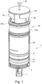
- Fig. 1 shows an isometric view of a device 1, which is described in more detail with reference to the following figures.
- Figure 2 shows the device 1 in a schematic representation in a partially sectioned representation.
- the device 1 is in a first state, which is a basic position when the device 1 was delivered and is shown in FIG Fig. 1 is equivalent to.
- the device 1 has a first chamber 2 which has a variable effective volume.
- the first chamber 2 has a cylindrical section or cylinder 3 in which a wall 4 is displaceably mounted.
- the cylinder 3 is a circular cylinder and the wall 4 is a circular surface adapted to the internal dimensions of the cylinder 3.
- the wall 4 is displaceable along a longitudinal axis of the cylinder 3.
- the chamber 2 has an opening 5 formed on a transverse surface of the cylinder 3.
- a connection part 6 is provided which is designed for connection to an external element, such as a cannula or needle.
- a septum 7 is provided with which a connection with the first chamber 2 can be reversibly established and closed again.
- the first chamber 2 can be filled with body fluid by means of the external element and the opening 5.
- the wall 4 has at least one opening 8, in the illustrated case several openings 8, which can be optionally closed or opened by means of a barrier 9 designed as a (umbrella) valve.
- the wall 4 also has a section 10 which extends in the direction of displacement (longitudinal axis) and on which seals 11 are provided which seal the first chamber 2 during the movement with respect to the wall 4.
- the seals 11 are in the form of O-rings which extend in the circumferential direction around the longitudinal axis.
- the Seals 11 are arranged in receptacles in section 10. The seals 11 produce a seal between the wall and the cylinder 3.
- a selection means 12 designed as a filter is connected to the wall 4 and can be displaced in the longitudinal direction of the cylinder 3 together with the barrier 9 designed as a valve.
- the wall 4 is connected to a guide 13, which in turn is designed as a cylindrical element in the case shown in the exemplary embodiment and extends away from the wall 4.
- a second chamber 14 is arranged on the guide 13 and can be displaced in the guide 13 in the longitudinal axis of the cylinder 3 and the guide 13.
- the second chamber 14 is designed as a container which has a negative pressure.
- the second chamber has a constant effective size.
- the second chamber 14 is closed by means of a sealing means 15.
- the second chamber 14 is held in the guide 13 by a holder 16 which has an outside dimension that is adapted to the inside dimensions of the guide 13.
- the holder 16 is slidably displaceable in the guide 13.
- the holder 16 has an O-ring 17 arranged in a circumferential groove around the holder 16.
- a blocking means 18 between guide 13 and bracket 16 is provided, which is designed as a break-off tab.
- the blocking means 18 is arranged between a stop section 19 of the holder 16 extending in the transverse direction of the longitudinal axis and an end section of the guide 13.
- FIG 3 is the state of the device 1 according to Figure 1 and FIG. 2 in a state after being filled with body fluid, blood shown here.
- the device 1, here the first chamber 2 is filled by connecting the connecting part 6 to a cannula and moving the wall 4 to increase the effective size of the first chamber 2, the cannula being inserted into a blood-filled lumen of a human or animal Body was stabbed at the end.
- the body fluid is sucked into the first chamber 2.
- the wall 4 is moved in that a grip section 24, which is formed on the guide 13 transversely to the longitudinal axis of the device 1, is gripped and the wall 4 is pulled backwards along the longitudinal axis.
- the grip section 24 is delimited by projections 24a, 24b that are spaced apart in a longitudinal direction.
- the projections 24a, 24b run along the circumference around the guide 13.
- the barrier 9 designed as an umbrella valve is closed, so that the first chamber 2 receives the body fluid and, when the cannula is separated again from the connecting part 6, the body fluid sterile in the first Chamber 2 is.
- a substance 21 which enlarges or changes the inner surface is provided in the first chamber 2, which substance can have an indicating effect on the formation of autologous proteins.
- Centrifugation can take place after or during the sterile incubation.
- the resulting state of the device 1 is in FIG Figure 4 shown.
- the blocking agent 18 was removed prior to centrifugation.
- the Figure 4 shows the state of the device 1 after centrifugation, in which on the one hand the body fluid, here blood, was separated into the individual phases and a movement of the guide 13, the wall 4 and the second chamber 14 was induced by the forces occurring during the centrifugation .
- the body fluid can be separated into individual phases and, in particular, one of the phases can be transferred into the second chamber 14 during centrifugation.
- the second chamber 14 or the holder 16 for the second chamber 14 can move relative to the guide 13, so that the holder 16 together with the second chamber 14 extends along the longitudinal axis of the guide 13 or the first chamber 2 is moved, the sealing means 15 of the second chamber 14 being pierced by an opener 22 configured as a piercing means, and the second chamber 14 thus being opened.
- the second chamber 14 is thus fluidically connected to the filter 12 and the valve 9.
- the container in the form of the second chamber 14 can be removed from the guide 13.
- a user can grasp the device 1 by a handle 23, which is formed on the end of the holder 16, and take it out of the centrifuge.
- the device 1 can then be held laterally on the handle section 24 and the holder 16 can be pulled out of the guide 13.
- the sealing means 15 of the second chamber 14 is closed again.
- the container in the form of the second chamber 14 can be removed from the holder 16.
- the separated phase located in the second chamber 14 was processed in a sterile manner and transferred in a sterile manner from the first chamber 2 to the second chamber 14 without a process step being required by a user.
- Fig. 5 shows a detailed view of the device 1.
- the curved arrows 25 schematically indicate a fluid path that results when the barrier 9 is open.
- the barrier 9 designed as an umbrella valve releases the openings 8 in the wall 4.
- the release of the openings 8 is based essentially on the pressure of the body fluid, which results from the displacement of the wall 4 in the direction of the opening 5; the displacement of the wall 4 is indicated by means of the three arrows on the right and left. Fluid flows from the first chamber 2 through the openings 8, through the selection means 12, and further through the opener 22 into the second chamber 14.
Description
Die vorliegende Erfindung betrifft eine Vorrichtung und ein Verfahren zum Überführen von Körperflüssigkeiten, sowie eine Verwendung.The present invention relates to a device and a method for transferring body fluids, as well as a use.
Vorrichtungen für die Separation einzelner Blutphasen, beispielsweise mittels der Anwendung einer Zentrifuge, oder für die Herstellung und Abtrennung biologisch aktiver Substanzen, wie beispielsweise autologen Proteinen, sind bekannt.Devices for the separation of individual blood phases, for example by using a centrifuge, or for the production and separation of biologically active substances, such as autologous proteins, are known.
Vor diesem Hintergrund ist es eine Aufgabe der Erfindung, eine Vorrichtung und ein Verfahren sowie eine Verwendung bereitzustellen, die bzw. das einen Transfer von einer Phase einer Körperflüssigkeit verbessert, wobei eine Verbesserung darin gesehen werden kann, eine möglichst geringe Anzahl von Verfahrensschritten eines Anwenders zu ermöglichen, die Handhabung zu verbessern und/oder einen Transfer des Körperfluids möglichst steril durchzuführen.Against this background, it is an object of the invention to provide a device and a method as well as a use which improves a transfer of a phase of a body fluid, wherein an improvement can be seen in the smallest possible number of method steps of a user make it possible to improve the handling and / or to carry out a transfer of the body fluid as sterile as possible.
Die Aufgabe wird gelöst durch den Gegenstand des unabhängigen Patentanspruchs. Vorteilhafte Ausführungsformen sind Gegenstand der abhängigen Patentansprüche und ergeben sich aus der nachfolgenden Beschreibung.The object is achieved by the subject matter of the independent patent claim. Advantageous embodiments are the subject matter of the dependent claims and emerge from the following description.
Es wird ein erster Aspekt mit einer Vorrichtung zur Aufnahme eines Körperfluids beschrieben, wobei die Vorrichtung eine erste Kammer, die eine verschiebliche Wandung aufweist, und eine zweite Kammer, mit konstanter effektiver Größe, die in Bezug auf die verschiebliche Wandung bewegbar ist, umfasst, wobei die Vorrichtung ausgestaltet ist, bei einer längsaxialen Bewegung der zweiten Kammer in Bezug auf die verschiebliche Wandung die erste Kammer und die zweite Kammer zu verbinden und bei einer Bewegung der zweiten Kammer zusammen mit der verschieblichen Wandung Körperfluid von der ersten Kammer in die zweite Kammer zu überführen. Hierdurch kann eine einfach ausgestaltete und einfach handhabbare Vorrichtung geschaffen werden, bei der eine längsaxiale Bewegung die Überführung bewirken kann. Ferner wird ein zweiter Aspekt beschrieben, gemäß dem der strukturelle Aufbau der Vorrichtung gemäß dem ersten Aspekt verwendet werden kann, wobei eine Vorrichtung mit einer ersten Kammer zur Aufnahme eines Körperfluids und einer zweiten Kammer beschrieben wird. Bei der Zentrifugation zur Separation der Phasen des Körperfluids kann die erste und die zweite Kammer verbunden werden und Körperfluid bei der Zentrifugation mittels der Zentrifugalkraft aus der ersten Kammer in die zweite Kammer überführt werden Die Anzahl der Verfahrensschritte eines Anwenders wird reduziert. Gemäß dem zweiten Aspekt kann vorgesehen sein, dass die erste Kammer keine verschiebliche Wandung aufweist, sondern als ein Behältnis ausgeführt ist, welches ein im Wesentlichen konstantes Volumen und einen Unterdruck aufweist.A first aspect is described with a device for receiving a body fluid, the device comprising a first chamber, which has a displaceable wall, and a second chamber, of constant effective size, which is movable with respect to the displaceable wall, wherein the device is designed to connect the first chamber and the second chamber with a longitudinal axial movement of the second chamber with respect to the displaceable wall and to transfer body fluid from the first chamber into the second chamber together with the displaceable wall when the second chamber moves . In this way, a simply configured and easy-to-use device can be created in which a longitudinal axial movement can bring about the transfer. Furthermore, a second aspect is described, according to which the structural design of the device according to the first aspect can be used, a device having a first chamber for receiving a body fluid and a second chamber being described. During centrifugation to separate the phases of the body fluid, the first and second chambers can be connected and during centrifugation body fluid can be transferred from the first chamber into the second chamber by means of centrifugal force. The number of process steps for a user is reduced. According to the second aspect, it can be provided that the first chamber does not have a movable wall, but is designed as a container which has an essentially constant volume and a negative pressure.
Es wird auch ein dritter Aspekt einer Vorrichtung beschrieben, gemäß dem der strukturelle Aufbau wie die Vorrichtung gemäß dem ersten Aspekt beschrieben ist, wobei die Vorrichtung eine erste Kammer zur Aufnahme eines Körperfluids und eine zweite Kammer aufweist. Die Vorrichtung ist ausgestaltet - insbesondere nach einer Zentrifugation und einer Separation der Phasen des Körperfluids - eine längsverschiebliche Bewegung auszuführen, bei der die Vorrichtung zusammengedrückt und Körperfluid von der ersten Kammer in die zweite Kammer überführt wird. Hierdurch kann eine einfach ausgestaltete und einfach handhabbare Vorrichtung beschrieben werden.A third aspect of a device is also described, according to which the structural design is described like the device according to the first aspect, the device having a first chamber for receiving a body fluid and a second chamber. The device is designed - in particular after centrifugation and a separation of the phases of the body fluid - to perform a longitudinally displaceable movement in which the device is compressed and body fluid is transferred from the first chamber to the second chamber. In this way, a simply configured and easy-to-use device can be described.
Es wird der Grundgedanke beschrieben, bei einer Zentrifugation die wirkenden Kräfte auszunutzen, um eine durch die Kräfte induzierte Bewegung zu ermöglichen, bei der Kammern miteinander verbunden werden können und ein Transfer bzw. eine Überführung des Körperfluids bei der Zentrifugation aufgrund der wirkenden Kräfte zumindest teilweise zwischen den Kammern ermöglicht wird. Es wurde erkannt, dass für die Separation bzw. Trennung der einzelnen Phasen bzw. Komponenten von Körperfluiden Kräfte aufgebracht werden, die neben der Separation bzw. Trennung der einzelnen Phasen für einen Transfer einer Phase von einer Kammer in eine andere Kammer genutzt werden können.The basic idea is described of using the forces acting during centrifugation in order to enable a movement induced by the forces, in which chambers can be connected to one another, and at least a transfer or transfer of the body fluid during centrifugation due to the forces acting is partially made possible between the chambers. It has been recognized that for the separation or separation of the individual phases or components of body fluids, forces are applied which, in addition to the separation or separation of the individual phases, can be used for a transfer of a phase from one chamber to another chamber.
Der erste Aspekt kann mit dem zweiten Aspekt sowie der erste Aspekt mit dem dritten Aspekt kombiniert werden. Es kann auch vorgesehen sein, dass der zweite und der dritte Aspekt miteinander kombiniert werden können, um bspw. eine zumindest teilweise Überführung während einer Zentrifugation und im Anschluss an die Zentrifugation eine weitere oder abschließende Überführung von Körperfluid zu ermöglichen.The first aspect can be combined with the second aspect and the first aspect can be combined with the third aspect. It can also be provided that the second and third aspects can be combined with one another, for example to enable at least partial transfer during centrifugation and, following centrifugation, further or subsequent transfer of body fluid.
Es kann eine Vorrichtung bereitgestellt werden, die eine Entnahme, eine Modifizierung, eine Separation, eine Isolierung und/oder eine Lagerung von Körperfluidkomponenten, insbesondere von Phasen, die mittels einer Zentrifugation voneinander separiert werden können, mittels einer einzigen Vorrichtung ermöglicht. Hierdurch kann eine möglichst sterile Handhabung von Körperfluiden gewährleistet werden. Der Anwender muss keine Schritte mehr durchführen, die großer Übung und/oder Erfahrung bedürfen.A device can be provided which enables removal, modification, separation, isolation and / or storage of body fluid components, in particular phases, which can be separated from one another by means of centrifugation, by means of a single device. In this way, the most sterile possible handling of body fluids can be ensured. The user no longer has to carry out steps that require great practice and / or experience.
Der Begriff "Körperfluid" im Sinne der Beschreibung umfasst ein Fluid des menschlichen oder tierischen Körpers.. Der Begriff umfasst im Wesentlichen eine Flüssigkeit, wobei gasförmige oder feste Anteile nicht ausgeschlossen sein sollen. Der Begriff Körperfluid umfasst insbesondere Speichel, Lymphflüssigkeit, Urin, Knochenmark und bevorzugt Blut. Der Begriff "Phase" oder "Komponente" des Körperfluids umfasst Anteile, die mittels einer Zentrifugation voneinander getrennt werden können.The term “body fluid” in the sense of the description comprises a fluid of the human or animal body. The term essentially comprises a liquid, whereby gaseous or solid components should not be excluded. The term body fluid includes in particular saliva, lymph fluid, urine, bone marrow and preferably blood. The term “phase” or “component” of the body fluid encompasses portions that can be separated from one another by means of centrifugation.
Der Begriff "Kammer" im Sinne der Beschreibung umfasst einen Hohlraum, der das Körperfluid und/oder einzelne oder mehrere Phasen des Körperfluids aufnehmen kann. Die Wandungen des Hohlraums können bevorzugt starr ausgebildet sein. Insbesondere können Seitenwandungen der Kammer, d.h. Wandungen, die sich längs der Längsachse der Kammer strecken, starr ausgebildet sein. Die effektive Größe des Hohlraums kann je nach Ausführungsform konstant (zweite Kammer) oder variabel (erste Kammer) sein, wobei der Hohlraum eine maximale Größe haben kann und durch Bewegen einer Wandung, die sich insbesondere in einer Richtung quer zur Längsachse der Kammer erstrecken kann, die Größe verringert oder vergrößert werden kann, um beispielsweise das enthaltene Fluid aus der Kammer (der ersten Kammer) zu drücken oder in die Kammer (erste Kammer) hineinzusaugen. Im Sinne der vorliegenden Beschreibung ist die zweite Kammer gegenüber der Umgebung geschlossen, wobei eine Kammer insbesondere nach Ausbildung einer sterilen Verbindung zum menschlichen oder tierischen Körper geöffnet werden kann, um die Körperflüssigkeit aufzunehmen oder abzugeben. In einer bevorzugten Ausführungsform kann eine der beiden Kammern aus der Vorrichtung entfernt werden. Eine der Kammern kann derart eingerichtet und angeordnet sein, um von der Vorrichtung getrennt zu werden, wobei der Inhalt der Kammer steril in der Kammer verbleiben kann. Die Kammern können derart ausgestaltet sein, dass diese voneinander separiert werden können, und zumindest eine Kammer kann geschlossen verbleiben oder nach der Separation geschlossen sein. Insbesondere kann die zu entnehmende Kammer in einem Anfangszustand bzw. Auslieferungszustand der Vorrichtung steril verschlossen sein. Alternativ oder zusätzlich ist auch die andere Kammer in diesem Zustand steril verschlossen. Die Kammern können in diesem Zustand geschlossene Einheiten bilden. Eine mögliche Verbindung bzw. Verbindungselemente, die die Verbindung der Kammern ermöglichen, können steril, insbesondere in einem Zwischenraum zwischen den Kammern, vorliegen.The term “chamber” in the sense of the description comprises a cavity which can accommodate the body fluid and / or individual or several phases of the body fluid. The walls of the cavity can preferably be rigid. In particular, side walls of the chamber, ie walls that extend along the longitudinal axis of the chamber, can be rigid. The effective size of the cavity can be constant (second chamber) or variable (first chamber), depending on the embodiment, whereby the cavity can have a maximum size and by moving a wall, which can in particular extend in a direction transverse to the longitudinal axis of the chamber, the size can be reduced or increased in order, for example, to push the contained fluid out of the chamber (the first chamber) or to suck it into the chamber (first chamber). In the context of the present description, the second chamber is closed to the environment, with one chamber being able to be opened, in particular after a sterile connection to the human or animal body has been established, in order to absorb or release the body fluid. In a preferred embodiment, one of the two chambers removed from the device. One of the chambers can be set up and arranged to be separated from the device, wherein the contents of the chamber can remain sterile in the chamber. The chambers can be designed in such a way that they can be separated from one another, and at least one chamber can remain closed or be closed after the separation. In particular, the chamber to be removed can be closed in a sterile manner in an initial state or delivery state of the device. As an alternative or in addition, the other chamber is also closed in a sterile manner in this state. In this state, the chambers can form closed units. A possible connection or connection elements which enable the chambers to be connected can be sterile, in particular in an intermediate space between the chambers.
Eine Kammer konstanter effektiver Größe ist eine Kammer, bei der das Gesamtvolumen, das in die Kammer eingefüllt werden kann, gleich bzw. konstant bleibt. Die Wandungen der Kammer mit konstanter effektiver Größe können als unverschieblich zueinander ausgestaltet sein. Insoweit kann der Ausdruck "Kammer mit konstanter effektiver Größe" gleichbedeutend mit "Kammer mit unverschieblichen Wandungen" sein. Dabei ist nicht ausgeschlossen, dass sich die Wandungen der Kammer mit konstanter effektiver Größe, insbesondere geringfügig, wölben oder entfalten können. Eine Kammer konstanter effektiver Größe kann auch ein innerhalb eines faltenbalgähnlichen Konstrukts, das endseitig zumindest an einer Seite geschlossen ist, ausgebildeter Hohlraum sein, der mit Fluid gefüllt werden kann und sich bei der Füllung zumindest teilweise entfaltet. Anstoßabschnitte zwischen den Wandungen der Kammer mit konstanter effektiver Größe können fest ausgeführt sein. Die Wandungen können fest miteinander verbunden sein. Bevorzugt weist die Kammer mit konstanter effektiver Größe einen Unterdruck auf.A chamber of constant effective size is a chamber in which the total volume that can be filled into the chamber remains the same or constant. The walls of the chamber with a constant effective size can be designed to be immovable with respect to one another. In this respect, the expression “chamber with constant effective size” can be synonymous with “chamber with immovable walls”. It is not excluded here that the walls of the chamber can bulge or unfold with a constant effective size, in particular slightly. A chamber of constant effective size can also be a cavity formed within a bellows-like construct, which is closed at least on one side at the end, which can be filled with fluid and at least partially unfolds during the filling. Abutment sections between the walls of the chamber with a constant effective size can be made fixed. The walls can be firmly connected to one another. The chamber preferably has a negative pressure with a constant effective size.
Die Vorrichtung kann daher derart eingerichtet und ausgestaltet sein, um bei Zentrifugation zur Separation von Phasen des Körperfluids die erste und die zweite Kammer zu verbinden und das Körperfluid bei dieser Zentrifugation mittels der dabei wirkenden Kräfte aus der ersten Kammer in die zweite Kammer zu überführen Ebenso können die erste Kammer, die zweite Kammer und/oder nachfolgend beschriebene Elemente der Vorrichtung eingerichtet, angeordnet oder ausgestaltet sein, diese Funktion zu ermöglichen oder zu unterstützen.The device can therefore be set up and designed to connect the first and second chambers during centrifugation to separate phases of the body fluid and to transfer the body fluid from the first chamber into the second chamber by means of the forces acting in this centrifugation the first chamber, the second chamber and / or elements described below set up, arranged or designed of the device to enable or support this function.
In einer erfindungsgemäßen Ausführungsform sind die beiden Kammern der Vorrichtungen nach Aufnahme des Körperfluids in der ersten Kammer gegenüber der Umgebung (weiterhin) abgeschlossen. Die Vorrichtung kann insbesondere steril ausgeliefert werden. Dann kann die Vorrichtung steril mit Körperfluid befüllt werden. Im Folgenden kann das Körperfluid steril in der Vorrichtung prozessiert werden. Die Sterilität kann durch den gesamten Prozess, insbesondere der Blutbefüllung, Separation der Phasen und Überführung einer Phase in die zweite Kammer, aufrechterhalten werden bzw. gewährleistet sein.In one embodiment according to the invention, the two chambers of the devices are (further) closed off from the environment after the body fluid has been taken up in the first chamber. The device can in particular be delivered sterile. The device can then be filled with body fluid in a sterile manner. In the following, the body fluid can be processed in the device in a sterile manner. The sterility can be maintained or guaranteed through the entire process, in particular the blood filling, separation of the phases and transfer of a phase into the second chamber.
Insbesondere kann die erste Kammer für eine Körperfluidentnahme, insbesondere eine Blutentnahme, aus dem Körper eingerichtet oder ausgestaltet sein. An der Kammer kann eine, insbesondere wiederverschließbare, insbesondere bevorzugt automatisch bzw. selbsttätig wiederverschließbare, Öffnung oder ein Verbindungsteil ausgebildet sein, mittels der bzw. dem eine Körperfluidentnahme mittels der Vorrichtung durchführbar ist. Vorzugsweise ist ein Septum als Verschlussmembran an einer Öffnung der ersten Kammer derart angeordnet, dass ein, insbesondere automatische bzw. selbsttätige, Wiederverschließen nach einer Befüllung möglich ist. Hierzu kann endseitig an der ersten Kammer, insbesondere an einem sich verengenden Bereich, eine Öffnung mit einem Septum angeordnet sein. Das Septum kann zum Befüllen der Kammer durchstochen und nach dem Befüllen wieder geschlossen werden. Die erste Kammer kann eine endseitige Wandung aufweisen, die verschieblich an der Seitenwandung bewegt werden kann, um das effektive Volumen der Kammer zu verändern. Beispielsweise kann die erste Kammer endseitig eine mittels eines Stempels oder eines Kolbens bewegbare Wandung aufweisen. Die erste Kammer kann einen "zylindrischen Abschnitt" aufweisen bzw. als solche ausgebildet sein, der einen röhrenförmigen Abschnitt aufweist, der von einer Mantelfläche und zwei weiteren Querflächen, die im Wesentlichen Schnittflächen der Mantelfläche sein können, eingeschlossen sein kann. An einer der Querflächen kann die Öffnung mit dem Septum ausgebildet sein und die andere Querfläche kann die verschiebliche Wandung sein. Die Querfläche mit der Öffnung kann einstückig mit der Seitenwandung ausgebildet sein. Der "zylindrische Abschnitt" kann als eine ebene Kurve in einer Ebene dargestellt werden, die entlang einer Geraden, die nicht in der zuvor genannten Ebene enthalten ist, um eine vorgegebene Strecke verschoben wird. Die ebene Kurve kann an der Anfangs- und Endlage der Verschiebung eine oder beide der zuvor genannten Querflächen sein. Die ebene Kurve kann insbesondere ein Kreis, eine Ellipse, ein Polygon oder eine Kombination der zuvor genannten Formen sein. Besonders bevorzugt ist als zylindrischer Abschnitt in dem Sinne der Beschreibung ein senkrechter Kreiszylinder. Die verschiebliche Wandung weist im Falle eines senkrechten Kreiszylinders eine im Querschnitt im Wesentlichen kreisförmige Form auf. Die verschiebliche Wandung der Kammer kann insbesondere als Endfläche eines in einem Zylinder verschieblichen Kolbens vorliegen. Die Öffnung der ersten Kammer mit dem Verbindungsteil und/oder dem Septum kann an der Wand ausgebildet sein, die als Querfläche der verschieblichen Wandung gegenüberliegt. Es kann vorgesehen sein, dass die Befüllung der ersten Kammer mittels eines Anschlusses einer Nadel oder Kanüle am Verbindungsteil und durch eine Bewegung der verschieblichen Wandung der ersten Kammer erfolgt, wobei die Bewegung der verschieblichen Wandung der ersten Kammer in einer besonders bevorzugten Ausführungsform mittels eines Anschlagelements begrenzt ist. Vorzugsweise ist das Füllvolumen der ersten Kammer durch die verschiebbare Wandung variabel. Das Füllvolumen der ersten Kammer kann 2 bis 500 ml betragen. Es ist möglich, dass das Füllvolumen der ersten Kammer 5 bis 500 ml, bevorzugt 5 bis 300 ml, ferner bevorzugt 5 bis 150 ml, weiter bevorzugt 5 bis 100 ml, vorzugsweise 5 bis 50 ml, besonders bevorzugt 10 bis 15 ml, beträgt. Es kann auch vorgesehen sein, dass die erste Kammer ein Vakuum aufweist und eine Befüllung nach dem Vakuumprinzip erfolgen kann. Im Falle, dass die erste Kammer ein Vakuum aufweist, herrscht in der ersten Kammer ein Unterdruck, so dass zur Befüllung der ersten Kammer keine verschiebliche Wandung benötigt wird.In particular, the first chamber can be set up or designed for taking body fluid, in particular taking blood, from the body. An opening or a connecting part can be formed on the chamber, in particular resealable, particularly preferably automatically or automatically resealable, by means of which body fluid can be removed by means of the device. A septum is preferably arranged as a sealing membrane at an opening of the first chamber in such a way that, in particular automatic or automatic, reclosing is possible after filling. For this purpose, an opening with a septum can be arranged at the end of the first chamber, in particular in a narrowing area. The septum can be pierced to fill the chamber and closed again after filling. The first chamber can have an end wall which can be moved displaceably on the side wall in order to change the effective volume of the chamber. For example, the end of the first chamber can have a wall that can be moved by means of a ram or a piston. The first chamber can have a "cylindrical section" or be designed as such, which has a tubular section which can be enclosed by a jacket surface and two further transverse surfaces, which can essentially be cut surfaces of the jacket surface. The opening with the septum can be formed on one of the transverse surfaces and the other transverse surface can be the displaceable wall. The transverse surface with the opening can be formed in one piece with the side wall. The "cylindrical section" can be represented as a planar curve in a plane which is displaced by a predetermined distance along a straight line which is not contained in the aforementioned plane. The planar curve can be one or both of the aforementioned transverse surfaces at the start and end positions of the displacement. The flat curve can in particular be a circle, an ellipse, a polygon or a combination of the aforementioned shapes. A vertical circular cylinder is particularly preferred as the cylindrical section in the sense of the description. In the case of a vertical circular cylinder, the displaceable wall has an essentially circular cross-section Shape on. The displaceable wall of the chamber can in particular be present as an end face of a piston displaceable in a cylinder. The opening of the first chamber with the connecting part and / or the septum can be formed on the wall which is opposite the displaceable wall as a transverse surface. It can be provided that the first chamber is filled by connecting a needle or cannula to the connecting part and by moving the movable wall of the first chamber, the movement of the movable wall of the first chamber being limited in a particularly preferred embodiment by means of a stop element is. The filling volume of the first chamber is preferably variable due to the displaceable wall. The filling volume of the first chamber can be 2 to 500 ml. It is possible that the filling volume of the first chamber is 5 to 500 ml, preferably 5 to 300 ml, further preferably 5 to 150 ml, more preferably 5 to 100 ml, preferably 5 to 50 ml, particularly preferably 10 to 15 ml. It can also be provided that the first chamber has a vacuum and filling can take place according to the vacuum principle. In the event that the first chamber has a vacuum, there is a negative pressure in the first chamber, so that no movable wall is required to fill the first chamber.
Ein Septum im Sinne der Beschreibung umfasst einen sich üblicherweise von selbst verschließenden Verschluss, insbesondere eine elastomere Dichtung und/oder Verschlussmembran. Es kann aber auch vorgesehen sein, dass ein Septum im Sinne der Beschreibung einen Verschluss beschreibt, der von außen betätigt werden muss, damit der Verschluss wieder verschließt, beispielweise ein Schieber. Im Sinne der Beschreibung kann ein Septum auch ein selbstschließendes Ventil oder eine funktionsgleiche Struktur eines Verschlusses sein, der derart ausgestaltet ist, nach Einwirken (beispielsweise durch Druck und/oder eine Nadel) selbsttätig wieder zu verschließen.A septum in the sense of the description comprises a closure that usually closes by itself, in particular an elastomeric seal and / or closure membrane. However, it can also be provided that a septum in the sense of the description describes a closure which has to be actuated from the outside so that the closure closes again, for example a slide. For the purposes of the description, a septum can also be a self-closing valve or a functionally equivalent structure of a closure which is designed in such a way that it automatically closes again after it has acted (for example by pressure and / or a needle).
Der Begriff "Kolben" im Sinne der Beschreibung umfasst ein bewegliches Bauteil, das zusammen mit einem Gehäuse, insbesondere dem zylindrischen Abschnitt, einen abgeschlossenen Hohlraum (erste Kammer) bilden kann, dessen Volumen sich durch die Bewegung des Kolbens verändert. Der Kolben kann auf eine Platte oder Scheibe (verschiebliche Wandung), die in dem zylindrischen Abschnitt bewegt wird, reduziert sein.The term “piston” in the sense of the description comprises a movable component which, together with a housing, in particular the cylindrical section, can form a closed cavity (first chamber), the volume of which changes as a result of the movement of the piston. The piston can be reduced to a plate or disk (movable wall) which is moved in the cylindrical section.
In einer bevorzugten Ausführungsform weist die Vorrichtung eine Barriere zwischen der ersten Kammer und der zweiten Kammer auf, wobei die Barriere bei einer Befüllung der ersten Kammer vorzugsweise geschlossen ist. Die Barriere kann wahlweise einen Durchfluss von Fluid verhindern oder ermöglichen. Die Barriere kann insbesondere an der ersten Kammer angeordnet sein und eine oder mehrere Öffnungen der ersten Kammer, die einen Fluss zumindest eines Teils des Körperfluids in Richtung der zweiten Kammer ermöglichen, verschließen. Die Barriere und die eine oder die mehreren Öffnungen können an der der Öffnung für eine Körperfluidbefüllung gegenüberliegenden Wandung der Kammer angeordnet sein. Die Barriere kann Teil der ersten Kammer sein, so dass die Barriere zusammen mit der ersten Kammer gehandhabt und/oder bewegt werden kann.In a preferred embodiment, the device has a barrier between the first chamber and the second chamber, the barrier preferably being closed when the first chamber is filled. The barrier can optionally prevent or enable a flow of fluid. The barrier can in particular be arranged on the first chamber and close one or more openings of the first chamber, which allow a flow of at least part of the body fluid in the direction of the second chamber. The barrier and the one or more openings can be located opposite the opening for a body fluid filling Wall of the chamber be arranged. The barrier can be part of the first chamber so that the barrier can be handled and / or moved together with the first chamber.
In einer bevorzugten Ausführungsform kann das Körperfluid nach Entnahme bzw. Befüllen in die erste Kammer innerhalb der ersten Kammer modifiziert werden. Hierzu können Additive in der ersten Kammer vorgesehen sein. Typische Additive im Falle von menschlichem oder tierischem Blut als Körperfluid sind Antikoagulantien umfassend EDTA, Citrat, Heparin und/oder deren Derivate. In einer besonders bevorzugten Ausführungsform ist die innere Oberfläche der ersten Kammer vergrößert, beispielweise mittels eines die innere Oberfläche der Kammer bearbeitenden Verfahrens, welches die Rauigkeit der inneren Oberfläche vergrößert. In einer besonders bevorzugten Ausführungsform ist in der ersten Kammer eine die innere Oberfläche verändernde und/oder vergrößernde Substanz angeordnet, die eine induzierende Wirkung auf die Bildung autologer Proteine haben kann. Die oberflächenverändernden und/oder oberflächenvergrößernden Substanzen umfassen Glasmehl, Glasgranulat, Quarzmehl, Quarzsand, Korund, Kügelchen, Perlen, Sand und Metalle. Die oberflächenverändernden und/oder oberflächenvergrößernden Substanzen umfassen auch organische Verbindungen und Polymere sowie biogene oder biologische Substanzen, wie beispielweise Zellulose, Collagene, Alginate, Nukleinsäuren und andere von Zellen gebildete Proteine oder Metabolite. Die oberflächenverändernde und/oder oberflächenmodifizierende Substanz kann von im Wesentlichen fester, flüssiger oder gelartiger Konsistenz sein. In einer weiteren besonders bevorzugten Ausführungsform sind Additive wie Antikoagulantien und/oder eine die innere Oberfläche verändernde und/oder vergrößernde Substanz in der ersten Kammer angeordnet. Alternativ sind keine Additive in der ersten Kammer vorgesehen.In a preferred embodiment, the body fluid can be modified within the first chamber after it has been removed from or filled into the first chamber. For this purpose, additives can be provided in the first chamber. Typical additives in the case of human or animal blood as the body fluid are anticoagulants comprising EDTA, citrate, heparin and / or their derivatives. In a particularly preferred embodiment, the inner surface of the first chamber is enlarged, for example by means of a method which processes the inner surface of the chamber and which increases the roughness of the inner surface. In a particularly preferred embodiment, a substance which changes and / or enlarges the inner surface and which can have an inducing effect on the formation of autologous proteins is arranged in the first chamber. The surface-changing and / or surface-enlarging substances include glass powder, glass granules, quartz powder, quartz sand, corundum, spheres, pearls, sand and metals. The surface-changing and / or surface-enlarging substances also include organic compounds and polymers as well as biogenic or biological substances, such as cellulose, collagens, alginates, nucleic acids and other proteins or metabolites formed by cells. The surface-changing and / or surface-modifying substance can be of a substantially solid, liquid or gel-like consistency. In a further particularly preferred embodiment, additives such as anticoagulants and / or a substance that changes and / or enlarges the inner surface are arranged in the first chamber. Alternatively, no additives are provided in the first chamber.
Es ist möglich, dass in der ersten Kammer eine biologisch wirksame Substanz vorhanden ist oder diese in die erste Kammer mit dem schon eingefüllten Körperfluid eingebracht wird. Eine biologisch wirksame Substanz ist eine Substanz, die eine Veränderung der Physiologie bzw. des Metabolismus bewirkt. Beispiele für eine biologisch wirksame Substanz können Cortison, Gene oder DNA oder andere vorgenannte biogene oder biologische Substanzen sein.It is possible that a biologically active substance is present in the first chamber or that this is introduced into the first chamber with the body fluid that has already been filled. A biologically active substance is a substance that causes a change in physiology or metabolism. Examples of a biologically active substance can be cortisone, genes or DNA or other aforementioned biogenic or biological substances.
In einer bevorzugten Ausführungsform ist mindestens ein Öffner vorgesehen, der derart ausgestaltet ist, zumindest einen zwischen der ersten und der zweiten Kammer angeordneten Teilfluidpfad auszubilden, indem der Öffner ein Element ist und/oder auf ein Element einwirkt das den Teilfluidpfad blockiert bzw. unterbricht. Bei dem Öffner kann es sich beispielweise um ein Durchstechmittel, zwischen der ersten und der zweiten Kammer handeln, das auf ein Septum einwirkt. Nicht limitierende Beispiele für einen Öffner umfassen ein Ventil, ein auf ein Ventil einwirkendes Element, einen Schieber, ein auf einen Schieber einwirkendes Element und/oder ein Durchstechmittel. Es kann vorgesehen sein, dass der Öffner Teil eines Verschlusses sein kann; beispielsweise kann der Öffner ein Betätigungsabschnitt eines Schiebers sein.In a preferred embodiment, at least one opener is provided which is designed to form at least one partial fluid path arranged between the first and the second chamber, in that the opener is an element and / or acts on an element that blocks or interrupts the partial fluid path. The opener can be, for example, a piercing means between the first and the second chamber, which acts on a septum. Non-limiting examples of an opener include a valve, an element acting on a valve, a slide, an element acting on a slide and / or a piercing means. It can be provided that the opener can be part of a closure; for example, the opener can be an actuating section of a slide.
Der Öffner kann einen Verschluss der zweiten Kammer öffnen, insbesondere indem die zweite Kammer mittels eines Septums verschlossen ist, welches ein als Durchstechmittel zwischen der ersten Kammer und der zweiten Kammer ausgestalteter Öffner durchsticht. Das Durchstechmittel kann bevorzugt als ein- oder zweiendige Kanüle, ein- oder zweiendige Nadel und/oder ein oder mehrschneidige Klinge ausgestaltet sein. Bei Einbringen der erfindungsgemäßen Vorrichtung in eine handelsübliche Zentrifuge wie beispielsweise Festwinkel- oder Ausschwingzentrifugen kann in einer bevorzugten Ausführungsform der Öffner während einer Zentrifugation einen an der zweiten Kammer angebrachten Verschluss an einer Öffnung der zweiten Kammer öffnen. Vorzugsweise handelt es sich bei dem Öffner um ein Durchstechmittel und bei dem Verschluss der zweiten Kammer um eine auf die erste Kammer gerichtete endseitig angeordnete Dichtung, beispielweise einen Elastomerverschluss, der zweiten Kammer, mit der insbesondere eine Öffnung der zweiten Kammer wiederverschließbar ist.The opener can open a closure of the second chamber, in particular in that the second chamber is closed by means of a septum, which pierces an opener configured as a piercing means between the first chamber and the second chamber. The piercing means can preferably be designed as a single or double-ended cannula, a single or double-ended needle and / or a single-edged or multi-edged blade. When the device according to the invention is introduced into a commercially available centrifuge such as fixed-angle or swing-bucket centrifuges, in a preferred embodiment the opener can open a closure attached to the second chamber at an opening of the second chamber during centrifugation. The opener is preferably a piercing means and the closure of the second chamber is a seal, for example an elastomer closure of the second chamber, directed towards the first chamber, with which in particular an opening of the second chamber can be reclosed.
Der Begriff "Elastomere" umfasst Grundstoffe, die sich bei Zug- oder Druckbelastung elastisch verformen, aber danach wieder in ihre im Wesentlichen ursprüngliche Gestalt zurückfinden.The term "elastomers" encompasses basic materials that deform elastically when subjected to tensile or compressive loads, but then return to their essentially original shape.
Ferner kann, insbesondere zusätzlich zum Öffner und gegebenenfalls einem entsprechenden Element, auf das der Öffner einwirkt, zwischen der ersten und der zweiten Kammer die Barriere angeordnet sein. Die Barriere kann einen Fluss des Körperfluids aus der ersten Kammer in Richtung der zweiten Kammer verhindern. Die Barriere kann derart ausgestaltet sein, dass im Wesentlichen glatte Wandungen vorhanden sind, die mit dem Körperfluid in Kontakt kommen, so dass Öffnungen und/oder Unebenheiten, in die Bestandteile des Körperfluids in bestimmten Zuständen der Vorrichtung eindringen können, verringert und/oder vermieden werden. Die Barriere kann in Form eines Ventils ausgestaltet sein oder ein solches umfassen. Die Barriere kann einen Fluss des Körperfluids in Richtung der zweiten Kammer vor dem Öffner und dem Verschluss der zweiten Kammer verhindern. Die Barriere kann als rein physikalische Barriere bzw. Blockademittel, welche bzw. welches wahlweise schließt oder öffnet, ausgebildet sein. Die Barriere kann als Septum, welches mittels einer Nadel oder einem ähnlichen Durchstechmittel durchstochen werden kann, um einen Durchfluss zu ermöglichen, ausgestaltet sein. Ein Ventil als Barriere kann als Rückschlagventil oder "Duck bill valve" oder als Schirmventil, insbesondere angeordnet an der Außenseite einer für eine Befüllung vorgesehenen Öffnung gegenüberliegenden Wandung der ersten Kammer, ausgestaltet sein.Furthermore, in particular in addition to the opener and possibly a corresponding element on which the opener acts, the barrier can be arranged between the first and the second chamber. The barrier can prevent the body fluid from flowing out of the first chamber in the direction of the second chamber. The barrier can be designed in such a way that there are essentially smooth walls that come into contact with the body fluid, so that openings and / or unevenness into which constituents of the body fluid can penetrate in certain states of the device are reduced and / or avoided . The barrier can be designed in the form of a valve or comprise one. The barrier can prevent a flow of the body fluid towards the second chamber prior to the opener and the closure of the second chamber. The barrier can be designed as a purely physical barrier or blocking means, which or which optionally closes or opens. The barrier can be designed as a septum, which can be pierced by means of a needle or a similar piercing means in order to allow a flow through. A valve as a barrier can be configured as a check valve or "duck bill valve" or as an umbrella valve, in particular arranged on the outside of an opening provided for filling opposite the wall of the first chamber.
In einer bevorzugten Ausführungsform kann zwischen der ersten und zweiten Kammer ein Selektionsmittel angeordnet sein. Vorzugsweise kann das Selektionsmittel als ein Filter ausgestaltet sein. Ein geeigneter Filter kann ein Filter zur Größenselektion des durchdringenden Fluids sein. Es kann eine Porengröße eines Filters von im Wesentlichen 100 µm, 90 µm, 20 µm, 5 µm, 3,2 µm, 1 µm, 0,4 µm, 0,2 µm oder 0,1 µm gewählt werden. Alternativ sind Ionenaustauscher oder Sorbentien mit angebrachten Liganden möglich.In a preferred embodiment, a selection means can be arranged between the first and second chambers. The selection means can preferably be designed as a filter. A suitable filter can be a filter for size selection of the penetrating fluid. A filter pore size of essentially 100 µm, 90 µm, 20 µm, 5 µm, 3.2 µm, 1 µm, 0.4 µm, 0.2 µm or 0.1 µm can be selected. Alternatively, ion exchangers or sorbents with attached ligands are possible.
Vorzugsweise sind die Barriere und der Öffner derart angeordnet, dass der Öffner näher zur zweiten Kammer angeordnet ist als die Barriere. Die Barriere kann den Öffner vor dem Eintritt des Körperfluids schützen. Die Barriere kann auch den Austritt aus der ersten Kammer verhindern. Der Filter kann zwischen der Barriere und dem Öffner angeordnet sein. Der Öffner kann einen Verschluss der zweiten Kammer öffnen. Die Barriere, insbesondere in Form eines vorgenannten Rückschlagventils oder Schirmventils, kann insbesondere bei einem längsaxialen Verschieben geöffnet werden und der Öffner bei diesem längsaxialen Verschieben die zweite Kammer öffnen. Hierdurch kann eine Verbindung zwischen der ersten und der zweiten Kammer hergestellt werden, bei der zunächst mindestens zwei oder genau zwei Verschlüsse, zum Einen die Barriere und zum Anderen der Verschluss der zweiten Kammer, verwendet werden, um eine Sterilität weitestgehend sicherzustellen.The barrier and the opener are preferably arranged such that the opener is arranged closer to the second chamber than the barrier. The barrier can protect the opener from ingress of body fluid. The barrier can also prevent the exit from the first chamber. The filter can be arranged between the barrier and the opener. The opener can open a closure of the second chamber. The barrier, in particular in the form of an aforementioned check valve or umbrella valve, can in particular be opened in the event of a longitudinally axial displacement, and the opener can open the second chamber in the case of this longitudinally axial displacement. In this way, a connection can be established between the first and the second chamber in which at least two or exactly two closures, on the one hand the barrier and on the other hand the closure of the second chamber, are used to ensure sterility as far as possible.
In einer bevorzugten Ausführungsform weist die zweite Kammer einen Unterdruck auf, wodurch der Transfer zumindest eines Teils des Körperfluids zwischen der ersten und der zweiten Kammer vereinfacht werden kann. Es ist eine einfache Ausgestaltung einer zweiten Kammer mit konstanter effektiver Größe möglich. Ein Bewegen von Wandungen der Kammer zueinander, welches eine Veränderung der effektiven Größe der Kammer bewirkt, kann entfallen. Es kann alternativ oder zusätzlich vorgesehen sein, dass ein Luftauslass an der zweiten Kammer vorgesehen ist, der für einen Druckausgleich der zweiten Kammer ausgestaltet sein kann. Besonders bevorzugt kann der Luftauslass in Art einer Rückschlagarmatur ausgestaltet sein, bei der ein Schließelement in einer Richtung zwangsgeschlossen ist und in der anderen Richtung einen Fluss der Luft freigibt. Beispielsweise kann eine derartige Rückschlagarmatur eine Feder aufweisen, die das Schließelement in einer Richtung durch die Feder schließt und in der anderen Richtung den Luftdurchfluss von der Kammer nach außen freigibt. Als Schließelement kommen Kegel, Kugel, Klappe und/oder Membran in Betracht, die jeweils in einen entsprechenden Sitz gedrückt werden. Steht in der Richtung, in der das Schließelement einen Fluss freigibt ein Druck an, der die Kraft der Feder übersteigt, wird das Schließelement vom Sitz abgehoben und der Durchfluss ist frei. Es sind auch Ausführungsformen möglich, in denen keine Feder verwendet wird, beispielsweise eine Ausführungsform, in der das Schließelement im Wesentlichen nur durch einen höheren anstehenden Außendruck eines Fluids, die strömende Luft oder die Gewichtskraft des Schließelements schließt.In a preferred embodiment, the second chamber has a negative pressure, whereby the transfer of at least part of the body fluid between the first and the second chamber can be simplified. A simple design of a second chamber with a constant effective size is possible. Moving the walls of the chamber towards one another, which causes a change in the effective size of the chamber, can be dispensed with. As an alternative or in addition, it can be provided that an air outlet is provided on the second chamber, which air outlet can be designed for pressure equalization in the second chamber. Particularly preferably, the air outlet can be designed in the manner of a non-return valve, in which a closing element is positively closed in one direction and releases a flow of air in the other direction. For example, such a check valve can have a spring which closes the closing element in one direction by the spring and in the other direction releases the air flow from the chamber to the outside. A cone, ball, flap and / or membrane come into consideration as the closing element, each of which is pressed into a corresponding seat. If there is a pressure in the direction in which the closing element releases a flow that exceeds the force of the spring, the closing element is lifted from the seat and the flow is free. Embodiments are also possible in which no spring is used, for example one Embodiment in which the closing element closes essentially only by a higher external pressure of a fluid, the flowing air or the weight of the closing element.
Die zweite Kammer ist verschieblich gegenüber der Längsachse der ersten Kammer verschiebbar. Die zweite Kammer ist in einer Führung verschieblich angeordnet. Es ist ein Blockiermittel vorgesehen, dass die Relativbewegung von zweiter Kammer und erster Kammer zueinander verhindert. Das Blockiermittel kann als ein Anschlagelement ausgestaltet sein, das zur Aufhebung der Blockierung entfernt oder in eine andere Position gegenüber einem Stützelement gebracht werden kann. In einer bevorzugten Ausführungsform kann die Blockierung selbsttätig während einer Zentrifugation der Vorrichtung aufgehoben werden. In einer alternativen, besonders bevorzugten Ausführungsform kann die Blockierung durch den Anwender vor der Zentrifugation aufgehoben werden. Geeignete Blockiermittel im Sinne der Beschreibung umfassen Abbrechlaschen oder kompressierbare Federn. Die zweite Kammer kann relativ zur ersten Kammer verschieblich bewegt werden, wobei die zweite Kammer sich auf die erste Kammer zu bewegen kann. Neben der relativen Bewegung der ersten Kammer und zweiten Kammer kann die zweite Kammer bevorzugt eine Relativbewegung in bzw. an der Führung ausführen. Die Relativbewegung zwischen erster und zweiter Kammer kann durch eine Bewegung der Führung, die Teil eines Kolbens sein kann, bewirkt werden, indem die zweite Kammer zusammen mit der Führung relativ zur ersten Kammer bewegt wird. Die Vorrichtung kann mehrere Relativbewegungen ermöglichen: a) Zweite Kammer und Führung bewegen sich zusammen relativ zu ersten Kammer und b) zweite Kammer bewegt sich relativ zur Führung. Die zweite Kammer kann in einer besonders bevorzugten Ausführungsform als Behältnis, welches insbesondere einen Unterdruck aufweisen kann (beispielsweise als vacuum vial), ausgestaltet sein, welches in der Führung gelagert ist. Das Behältnis (zweite Kammer) kann von der Führung getrennt werden, nachdem eine Überführung von Körperfluid in die zweite Kammer erfolgte. Hierzu kann das Behältnis - eventuell zusammen mit einer Lagerung - aus der Führung entlang der Längsachse der Vorrichtung gezogen werden. Eine eventuell vorhandene Lagerung kann vom Behältnis (zweite Kammer) entfernt werden. Zur Verbesserung der Handhabung kann die Lagerung einen Stempel oder Griff aufweisen, der sich endseitig an der Lagerung entlang der Längsachse der Vorrichtung erstreckt.The second chamber is displaceable relative to the longitudinal axis of the first chamber. The second chamber is arranged displaceably in a guide. A blocking means is provided that prevents the relative movement of the second chamber and the first chamber with respect to one another. The blocking means can be designed as a stop element, which can be removed to unblock the block or can be brought into a different position with respect to a support element. In a preferred embodiment, the blockage can be lifted automatically during centrifugation of the device. In an alternative, particularly preferred embodiment, the blockage can be removed by the user before centrifugation. Suitable blocking means within the meaning of the description include snap-off tabs or compressible springs. The second chamber can be displaced relative to the first chamber, the second chamber being able to move towards the first chamber. In addition to the relative movement of the first chamber and the second chamber, the second chamber can preferably perform a relative movement in or on the guide. The relative movement between the first and second chambers can be brought about by a movement of the guide, which can be part of a piston, in that the second chamber is moved together with the guide relative to the first chamber. The device can enable several relative movements: a) the second chamber and guide move together relative to the first chamber and b) the second chamber moves relative to the guide. In a particularly preferred embodiment, the second chamber can be designed as a container, which can in particular have a negative pressure (for example as a vacuum vial), which is stored in the guide. The container (second chamber) can be separated from the guide after body fluid has been transferred into the second chamber. For this purpose, the container can be pulled out of the guide along the longitudinal axis of the device - possibly together with a bearing. Any storage that may be present can be removed from the container (second chamber). To improve handling, the mounting can have a stamp or handle which extends at the end of the mounting along the longitudinal axis of the device.
Es kann vorgesehen sein, dass die zweite Kammer eine Einfüllöffnung und eine zur Einfüllöffnung separate Entnahmeöffnung aufweist, die insbesondere je ein Septum aufweisen können. Hierdurch kann sichergestellt werden, dass die Einfüllöffnung nicht auch als Entnahmeöffnung verwendet werden muss, was eine Kontaminationsgefahr weiter verringert.It can be provided that the second chamber has a filling opening and a removal opening separate from the filling opening, which in particular can each have a septum. This makes it possible to ensure that the filling opening does not also have to be used as a removal opening, which further reduces the risk of contamination.
In einer Ausführungsform kann der Öffner und/oder eine Öffnung an der zweiten Kammer im Wesentlichen mittig bezogen auf den Querschnitt der Vorrichtung ausgebildet bzw. angeordnet sein. Hierdurch kann ein einfacher Aufbau ermöglicht werden. Es kann jedoch auch vorgesehen sein, dass der Öffner und/oder eine Öffnung an der zweiten Kammer außenmittig bezogen auf den Querschnitt der Vorrichtung ausgebildet bzw. angeordnet sind, was bei Festwinkelrotoren vorteilhaft sein kann.In one embodiment, the opener and / or an opening on the second chamber can be formed or arranged essentially centrally in relation to the cross section of the device. A simple structure can hereby be made possible. However, it can also be provided that the opener and / or an opening on the second chamber are designed or arranged externally in relation to the cross section of the device, which can be advantageous in the case of fixed-angle rotors.
Der Begriff "Feder" im Sinne der Beschreibung umfasst ein technisches Bauteil, das sich elastisch verformen lässt. Nicht limitierende Beispiele für Federn sind Schraubenfedern, Zugfedern und Stabfedern.The term “spring” in the context of the description includes a technical component that can be elastically deformed. Non-limiting examples of springs are coil springs, tension springs and bar springs.
Die erste Kammer weist einen Zylinder als zylindrischen Abschnitt und eine in dem Zylinder beweglich verschiebbare Führung, die die verschiebliche Wandung umfasst, auf. Die zweite Kammer kann als Behältnis an der Führung derart gelagert sein, dass das Behältnis bei der Zentrifugation relativ zur Führung in Richtung der ersten Kammer bewegt wird, um Körperfluid von der ersten Kammer in das Behältnis zu überführen. Die zweite Kammer kann sich in Längsrichtung der ersten Kammer bewegen. Die zweite Kammer kann eine konstante effektive Größe aufweisen.The first chamber has a cylinder as a cylindrical section and a guide which is movably displaceable in the cylinder and which comprises the displaceable wall. The second chamber can be mounted as a container on the guide in such a way that the container is moved relative to the guide in the direction of the first chamber during centrifugation in order to transfer body fluid from the first chamber into the container. The second chamber can move in the longitudinal direction of the first chamber. The second chamber can be of constant effective size.
Der Begriff "Führung" im Sinne der Beschreibung umfasst eine mit der verschieblichen Wandung verbundene Führungsfläche. Die Führungsfläche erstreckt sich im Wesentlichen parallel zur Längsachse der Vorrichtung. Entlang der Führungsfläche kann die zweite Kammer in Längsrichtung der Vorrichtung bewegt werden. Die Führungsfläche ist als zumindest abschnittsweise ausgebildete Mantelfläche eines Zylinders, die konzentrisch zur Mantelfläche des zylindrischen Abschnitts der ersten Kammer ausgerichtet ist, ausgebildet. Die Führung kann die zweite Kammer gleitverschieblich in Richtung der Längsachse der Vorrichtung aufnehmen; die Führungsfläche kann eine innere Mantelfläche sein. Die zweite Kammer kann unmittelbar oder mittelbar an der Führung gleiten. Im mittelbaren Falle kann die zweite Kammer in einer Halterung gehalten werden, die an der Führungsfläche der Führung gleiten kann. Zwischen der Halterung oder der zweiten Kammer und der Führungsfläche der Führung ist mindestens ein Dichtmittel in Umfangsrichtung angeordnet.The term “guide” in the sense of the description includes a guide surface connected to the displaceable wall. The guide surface extends essentially parallel to the longitudinal axis of the device. The second chamber can be moved in the longitudinal direction of the device along the guide surface. The guide surface is designed as a jacket surface of a cylinder which is at least partially configured and which is aligned concentrically to the jacket surface of the cylindrical section of the first chamber. The guide can accommodate the second chamber slidably in the direction of the longitudinal axis of the device; the guide surface can be an inner jacket surface. The second chamber can slide directly or indirectly on the guide. In the indirect case, the second chamber can be held in a holder that can slide on the guide surface of the guide. At least one sealing means is arranged in the circumferential direction between the holder or the second chamber and the guide surface of the guide.
Der Begriff "Halterung" im Sinne der Beschreibung umfasst ein technisches Bauteil, das zur Aufnahme der zweiten Kammer geeignet ist. Im Sinne der Beschreibung kann die Halterung als ein klammerartiges Bauteil ausgestaltet sein, welches eine als Behältnis ausgestaltete zweite Kammer umgreift. Die Halterung kann eine Öffnung aufweisen, die in Richtung einer Öffnung der zweiten Kammer gerichtet ist. Die Halterung kann eine zumindest abschnittsweise ausgestaltete im Wesentlichen zylinderförmige Mantelfläche aufweisen, die die zweite Kammer zumindest abschnittsweise umfangsseitig umgibt. Ferner kann die Halterung eine Basis aufweisen, die zur Anlage einer Außenseite eines Bodens der zweiten Kammer eingerichtet ist. Die Innenseite der Mantelfläche der Halterung kann bezogen auf ihren Innendurchmesser auf einen Außendurchmesser der zweiten Kammer angepasst sein. An dem der Basis gegenüberliegenden Ende können auf einer Höhe der zweiten Kammer angepasste Rastvorsprünge vorgesehen sein, so dass die zweite Kammer in Form einer Art eines Formschlusses in der Halterung gehalten wird. Die Halterung kann mit ihrer zumindest abschnittsweise als Mantelfläche eines Zylinders ausgestalteten Seitenwand an der Führung gleiten. Zur Verringerung des Kontakts zwischen der Führung und der Halterung können an der Halterung Vorsprünge ausgebildet sein, die an der Führungsfläche der Führung gleiten können. Insbesondere kann zwischen den Vorsprüngen eine Dichtung zwischen der Führung bzw. Führungsfläche und der Außenseite der Halterung ausgebildet sein.The term “holder” in the sense of the description includes a technical component that is suitable for receiving the second chamber. For the purposes of the description, the holder can be designed as a clamp-like component which surrounds a second chamber designed as a container. The holder can have an opening which is directed in the direction of an opening of the second chamber. The holder can have an essentially cylindrical jacket surface which is configured at least in sections and which surrounds the second chamber at least in sections on the circumferential side. Furthermore, the holder can have a base that is used to plant a Outside a bottom of the second chamber is set up. The inside of the lateral surface of the holder can be adapted to an outside diameter of the second chamber in relation to its inside diameter. At the end opposite the base, adapted latching projections can be provided at the level of the second chamber, so that the second chamber is held in the holder in the form of a type of form fit. The holder can slide on the guide with its side wall designed at least in sections as a jacket surface of a cylinder. To reduce the contact between the guide and the holder, projections can be formed on the holder, which can slide on the guide surface of the guide. In particular, a seal between the guide or guide surface and the outside of the holder can be formed between the projections.
In einer besonders bevorzugten Ausführungsform der Erfindung kann sich die Führung zusammen mit der verschieblichen Wandung der ersten Kammer relativ zur ersten Wandung - unter Veränderung der Größe der ersten Kammer - bewegen. Ferner kann sich die Halterung der zweiten Kammer relativ zu der Führung und damit auch relativ zu der ersten Wandung - ohne Veränderung der Größe der ersten Kammer - bewegen.In a particularly preferred embodiment of the invention, the guide can move together with the displaceable wall of the first chamber relative to the first wall - while changing the size of the first chamber. Furthermore, the holder of the second chamber can move relative to the guide and thus also relative to the first wall - without changing the size of the first chamber.
Die erste Kammer weist einen als Zylinder ausgebildeten zylindrischen Abschnitt auf und eine im Zylinder verschieblich gelagerte Wandung auf. Ferner kann die erste Kammer eine Öffnung an einem Verbindungsteil, insbesondere mit einem Septum, aufweisen. Das Verbindungsteil mit der Öffnung ist insbesondere außen an einer Querfläche des Zylinders, die der verschieblichen Wandung gegenüberliegt, ausgebildet. Die verschiebliche Wandung kann ein Ventil aufweisen, welches insbesondere bei einem Befüllen der ersten Kammer durch Verschiebung der verschieblichen Wandung zur Vergrößerung der ersten Kammer geschlossen ist und zur Überführung des Körperfluids in die zweite Kammer geöffnet wird. Die verschiebliche Wandung ist mit der Führung verbunden. Die Führung und die verschiebliche Wandung können derart ausgestaltet in dem Zylinder angeordnet sein, dass sie zusammen in dem Zylinder verschoben werden können, wobei die Führung an der der Öffnung der ersten Kammer gegenüberliegenden Seite zur verschieblichen Wandung angeordnet ist. Die verschiebliche Wandung weist zur Innenfläche des Zylinders, in dem sie verschieblich gelagert ist, mindestens ein Abdichtelement in Form eines O-Rings auf. Die verschiebliche Wandung kann insbesondere eine Öffnung mit einem Ventil aufweisen. Die verschiebliche Wandung kann ferner ein Selektionsmittel, insbesondere in Form eines Filters, welches zwischen der ersten Kammer und der zweiten Kammer angeordnet ist, aufweisen. Der Filter kann fest mit der verschieblichen Wandung verbunden sein. Zwischen dem Filter und der zweiten Wandung kann ein Öffner in Form eines Durchstechmittels, insbesondere in Form einer Kanüle, deren Spitze in Richtung der zweiten Kammer ausgerichtet ist, angeordnet sein. Die verschiebliche Wandung, der Filter, der Öffner und die Führung können als Teil eines Kolbens, der in dem Zylinder bzw. zylindrischen Abschnitt verschieblich bewegt werden kann, ausgestaltet sein oder einen Teil eines verschieblichen Zylinders, der in dem zylindrischen Abschnitt bzw. dem Zylinder verschieblich gelagert ist, bilden. Verschiebliche Wandung, Filter, Öffner und Führung können als Ganzes gehandhabt werden und in dem Zylinder bzw. zylindrischen Abschnitt als Ganzes bewegt werden. Insbesondere kann ein, insbesondere als Druckelement an der Führung ausgestaltetes, Betätigungselement vorgesehen sein, welches mit einer, insbesondere als Ventil ausgestalteten, Barriere, an der verschieblichen Wandung derart zusammenwirken kann, dass bei Ausübung eines Drucks, beispielsweise mittels der zweiten Kammer das Ventil öffnet. Bei Aufheben der Wirkung der Barriere, d.h. insbesondere Ausüben eines Drucks auf ein Verschlussteil des Ventils, kann die Barriere, insbesondere das Ventil, öffnen und die beiden Kammern miteinander in Fluidverbindung bringen. Die Barriere bzw. das Ventil kann auch ohne ein Betätigungselement ausgestaltet sein. Das Ventil kann beispielsweise aufgrund eines am Ventil anstehenden "Überdrucks" öffnen. Das Öffnen der Barriere geschieht vorzugsweise dann, wenn die zweite Kammer, die im bzw. an der Führung gelagert ist, sich zur Führung derart bewegt hat, dass das Durchstechmittel ein an einer Öffnung der zweiten Kammer vorgesehenes Dichtmittel durchstochen hat. Die zweite Kammer ist vorzugsweise als Behältnis, in dem ein Unterdruck vorliegt, ausgestaltet. Die zweite Kammer kann derart in bzw. an der Führung gelagert sein, dass sich die zweite Kammer auf das Durchstechmittel zubewegen kann, um eine Fluidverbindung zwischen der ersten Kammer und der zweiten Kammer herzustellen. Hierzu kann eine Ausführungsform vorgesehen sein, bei der die zweite Kammer auf das Durchstechmittel zubewegt wird, um das Dichtmittel der zweiten Kammer zu durchstechen und die zweite Kammer mittelbar oder unmittelbar in einer weiteren oder in der gleichen Bewegung auf ein Druckmittel drückt, welches das Ventil, welches an der verschieblichen Wandung ausgebildet ist, öffnet. Das Ventil kann auch derart ausgestaltet sein, das dieses bei einem Überdruck in der ersten Kammer öffnet. Das Ventil kann zusätzlich als Rückschlagventil ausgestaltet sein. Vorzugsweise kann die zweite Kammer zusammen mit der Führung und damit zusammen mit der verschieblichen Wandung, dem Filter und dem Durchstechmittel bewegt werden. Die zweite Kammer kann aber auch zusätzlich in der Führung gelagert sein, um eine Relativbewegung zur Führung durchzuführen. Hierzu kann die zweite Kammer als Teil eines Kolbens, der sich in einem zylindrischen Abschnitt einer Führung bewegen kann, ausgestaltet sein. Die Führung, die Teil eines Kolbens im zylindrischen Abschnitt der ersten Kammer ist, kann insbesondere ihrerseits einen zylindrischen Abschnitt aufweisen, in dem die zweite Kammer als Kolben ausgebildet ist. Insbesondere kann die als Behältnis ausgestaltete zweite Kammer gegenüber einer Innenwandung eines zylindrischen Abschnitts der Führung mittels eines oder mehrerer Dichtmittel, die insbesondere als O-Ring ausgestaltet sein können, abgedichtet sein. Es ist vorgesehen, dass eine Bewegung der zweiten Kammer innerhalb der Führung mittels eines Blockiermittels verhindert werden kann. Nach Entfernen des Blockiermittels und/oder außer Eingriff bringen des Blockiermittels kann eine Bewegung der zweiten Kammer relativ zur Führung erfolgen. Die Bewegung der Führung relativ zum zylindrischen Abschnitt bzw. Zylinder der ersten Kammer und die Bewegung der zweiten Kammer relativ zur Führung können im Wesentlichen auf der gleichen Längsachse erfolgen. Vorzugsweise kann nach Aufheben der Blockade der Bewegung des als Behältnis ausgebildeten zweiten Kammer, eine verschiebliche Bewegung der zweiten Kammer relativ zur Führung erfolgen, bei der in einem ersten Schritt zur Verbindung der ersten und der zweiten Kammer das Dichtmittel der zweiten Kammer vom Durchstechmittel durchstochen werden kann, indem die zweite Kammer relativ zur Führung bewegt wird und in einem nächsten Schritt, bei dem die zweite Kammer zusammen mit der Führung bewegt wird, das Ventil geöffnet werden. Aufgrund der bei der Zentrifugation wirkenden Kräfte wird bei der Zentrifugation neben einer Separation von Phasen des in der ersten Kammer enthaltenen Körperfluids eine Bewegung der zweiten Kammer in der Führung initiiert, die im Wesentlichen quer zu den ausgebildeten Phasengrenzen und/oder in Richtung der Längsachse der Vorrichtung ist. Durch die Bewegung der zweiten Kammer wird diese zunächst durch das Durchstechmittel geöffnet und dann das Ventil zwischen der ersten und der zweiten Kammer geöffnet. Ferner bewegt sich die Führung zusammen mit der verschieblichen Wandung in der gleichen Richtung wie die zweite Kammer zusammen mit dieser, so dass ein Druck auf das in der ersten Kammer befindliche Körperfluid ausgeübt wird und das Körperfluid aus der Kammer herausgedrückt und in die zweite Kammer mittels des Unterdrucks gesaugt wird. Die Bewegung und die Lagerung der Führung im zylindrischen Abschnitt der ersten Kammer und die Lagerung und Anordnung der zweiten Kammer in der Führung sind derart eingerichtet bzw. aufeinander abgestimmt, dass die beschriebenen relativen Bewegungen und insbesondere eine Überführung einer sich während der Zentrifugation ergebenden Phase in die zweite Kammer erfolgen. Die Vorrichtung kann nach der Zentrifugation zur Separierung der Phasen aus der Zentrifuge entnommen und ferner die zweite Kammer aus der Führung entfernt werden, wobei eine Bewegung ausgeführt wird, die entgegengesetzt der Bewegung ist, die zum Durchstechen des Dichtmittels geführt hat und dabei wird das Dichtmittel wieder geschlossen. Die zweite Kammer kann in einer gewünschten Art und Weise gehandhabt werden.The first chamber has a cylindrical section designed as a cylinder and a wall mounted displaceably in the cylinder. Furthermore, the first chamber can have an opening on a connecting part, in particular with a septum. The connecting part with the opening is formed in particular on the outside on a transverse surface of the cylinder which lies opposite the displaceable wall. The displaceable wall can have a valve which, in particular when the first chamber is filled, is closed by displacement of the displaceable wall to enlarge the first chamber and which is opened to transfer the body fluid into the second chamber. The movable wall is connected to the guide. The guide and the displaceable wall can be configured in the cylinder in such a way that they can be displaced together in the cylinder, the guide being arranged on the side opposite the opening of the first chamber to the displaceable wall. The displaceable wall has at least one sealing element in the form of an O-ring on the inner surface of the cylinder in which it is displaceably mounted. The displaceable wall can in particular have an opening with a valve. The displaceable wall can also have a selection means, in particular in the form of a filter, which is arranged between the first chamber and the second chamber. The filter can be firmly connected to the movable wall. Between the filter and the second wall, an opener in the form of a piercing means, in particular in the form of a cannula, the tip of which points in the direction of the second Chamber is aligned, be arranged. The displaceable wall, the filter, the opener and the guide can be configured as part of a piston that can be displaceably moved in the cylinder or cylindrical section, or as part of a displaceable cylinder that is displaceable in the cylindrical section or the cylinder is stored, form. Slidable wall, filter, opener and guide can be handled as a whole and moved as a whole in the cylinder or cylindrical section. In particular, an actuating element designed as a pressure element on the guide can be provided, which can interact with a barrier, particularly designed as a valve, on the movable wall in such a way that the valve opens when pressure is exerted, for example by means of the second chamber. When the effect of the barrier is canceled, ie in particular a pressure is exerted on a closure part of the valve, the barrier, in particular the valve, can open and bring the two chambers into fluid communication with one another. The barrier or the valve can also be designed without an actuating element. The valve can open, for example, due to an "overpressure" present at the valve. The barrier is preferably opened when the second chamber, which is mounted in or on the guide, has moved for the guide in such a way that the piercing means has pierced a sealing means provided at an opening of the second chamber. The second chamber is preferably designed as a container in which there is a negative pressure. The second chamber can be mounted in or on the guide in such a way that the second chamber can move towards the piercing means in order to establish a fluid connection between the first chamber and the second chamber. For this purpose, an embodiment can be provided in which the second chamber is moved towards the piercing means in order to pierce the sealing means of the second chamber and the second chamber directly or indirectly in a further or in the same movement presses on a pressure medium which the valve, which is formed on the movable wall opens. The valve can also be designed in such a way that it opens when there is overpressure in the first chamber. The valve can also be designed as a check valve. The second chamber can preferably be moved together with the guide and thus together with the displaceable wall, the filter and the piercing means. The second chamber can, however, also be mounted in the guide in order to carry out a movement relative to the guide. For this purpose, the second chamber can be designed as part of a piston that can move in a cylindrical section of a guide. The guide, which is part of a piston in the cylindrical section of the first chamber, can in particular have a cylindrical section in which the second chamber is designed as a piston. In particular, the second chamber designed as a container can be sealed off from an inner wall of a cylindrical section of the guide by means of one or more sealing means, which can in particular be designed as an O-ring. It is envisaged that movement of the second chamber within the guidance can be prevented by means of a blocking means. After removing the blocking means and / or disengaging the blocking means, the second chamber can move relative to the guide. The movement of the guide relative to the cylindrical section or cylinder of the first chamber and the movement of the second chamber relative to the guide can take place essentially on the same longitudinal axis. Preferably, after the blockage of the movement of the second chamber, which is designed as a container, has been lifted, the second chamber can be moved relative to the guide, during which the sealant of the second chamber can be pierced by the piercing agent in a first step to connect the first and second chambers by moving the second chamber relative to the guide and in a next step in which the second chamber is moved together with the guide, the valve is opened. Due to the forces acting during centrifugation, in addition to separating phases of the body fluid contained in the first chamber, a movement of the second chamber in the guide is initiated during centrifugation, which is essentially transverse to the phase boundaries and / or in the direction of the longitudinal axis of the device is. As a result of the movement of the second chamber, it is first opened by the piercing means and then the valve between the first and the second chamber is opened. Furthermore, the guide moves together with the movable wall in the same direction as the second chamber together with it, so that pressure is exerted on the body fluid located in the first chamber and the body fluid is pressed out of the chamber and into the second chamber by means of the Vacuum is sucked. The movement and mounting of the guide in the cylindrical section of the first chamber and the mounting and arrangement of the second chamber in the guide are set up or coordinated in such a way that the described relative movements and in particular a transfer of a phase resulting during centrifugation into the second chamber take place. After centrifugation, the device can be removed from the centrifuge to separate the phases and furthermore the second chamber can be removed from the guide, a movement being carried out which is opposite to the movement which led to the puncturing of the sealant, and the sealant becomes again in the process closed. The second chamber can be manipulated in a desired manner.
Es wird ein Verfahren beschrieben, bei dem Körperfluid von einer ersten Kammer in eine zweite Kammer überführt wird, wobei die effektive Größe der ersten Kammer mittels einer verschieblichen Wandung verändert wird und die zweite Kammer relativ zur verschieblichen Wandung bewegt wird. Insbesondere können die erste und die zweite Kammer bei einer Zentrifugation verbunden werden und das Körperfluid bei Zentrifugation mittels der dabei wirkenden Kräfte aus der ersten Kammer in die zweite Kammer überführt werden.A method is described in which body fluid is transferred from a first chamber into a second chamber, the effective size of the first chamber being changed by means of a movable wall and the second chamber being moved relative to the movable wall. In particular, the first and second chambers can be connected during centrifugation and, during centrifugation, the body fluid can be transferred from the first chamber into the second chamber by means of the forces acting in the process.
Es kann vorgesehen sein, dass ein Überführen zumindest eines Teils des Körperfluids durch ein Verschieben der zweiten Kammer in Richtung der ersten Kammer erfolgt. Während des Verschiebens kann ein Druckausgleich ausgeführt werden. Alternativ oder zusätzlich ist es möglich, dass das Verschieben druckausgleichsfrei erfolgt. Im Falle eines druckausgleichsfreien Verschiebens müssen keine Mittel vorgesehen werden, die für einen Druckausgleich verwendet werden müssen; die Vorrichtung kann vom konstruktiven Aufbau und/oder der Anzahl der Bauelemente vereinfacht werden. Im Falle eines Verschiebens mit einem Druckausgleich kann der Vorgang des Verschiebens möglicherweise einfacher ausgeführt werden, da kein erhöhter Druck in Schieberichtung vorliegt.It can be provided that at least part of the body fluid is transferred by moving the second chamber in the direction of the first chamber. Pressure equalization can be carried out during the movement. As an alternative or in addition, it is possible for the movement to take place without pressure compensation. In the case of a pressure equalization-free displacement, no means need to be provided that have to be used for pressure equalization; the device can be simplified in terms of its structural design and / or the number of components. In the case of a shift with a pressure equalization, the process of shifting can possibly be carried out more easily, since there is no increased pressure in the sliding direction.
Der Begriff "Zentrifugation" im Sinne der Beschreibung umfasst den Vorgang des Zentrifugierens einer Flüssigkeit in einer Zentrifuge, wie sie gemeinhin als Festwinkel- oder Ausschwingzentrifuge bezeichnet wird. Beispielsweise kann die Vorrichtung in Zentrifugen für 50 ml Falcon tubes eingebracht werden. Die Dauer der Zentrifugation kann zwischen einer bis 90 Minuten und bevorzugt zwischen einer bis 60 Minuten variiert werden. Es kann vorgesehen sein, dass das Körperfluid vor der Zentrifugation oder während der Zentrifugation inkubiert wird, wobei bevorzugt bei einer Inkubation während der Zentrifugation - eventuell bei niedrigeren Umdrehungszahlen - eine längere Dauer der Zentrifugation möglich ist. Geeignete relative Zentrifugalbeschleunigungen (RZB), mit denen das Verfahren durchgeführt werden kann, liegen im Bereich von 10 bis 10.000 G, bevorzugt 10 bis 5.000 G, besonders bevorzugt 10 bis 4.000 G. Nach der Zentrifugation kann die in der zweiten Kammer befindliche Phase des ursprünglich eingebrachten Körperfluids sofort verwendet werden. Alternativ kann die Körperfluidphase in der zweiten Kammer gekühlt, eingefroren und/oder lyophilisiert oder anderweitig verarbeitet werden. Im Sinne der Beschreibung umfasst eine "anderweitige Verarbeitung" das Hinzufügen von Additiven, des Portionieren in Kapseln, das Beschichten von zu implantierenden Vorrichtungen mit dem Körperfluid der zweiten Kammer und weitere mögliche Verwendungen. Nachfolgend wird eine Ausführungsform eines Verfahrensablaufs beschrieben:
Die erste Kammer kann mittels Bewegung einer verschieblichen Wandung der ersten Kammer mit Blut befüllt werden. Vorzugsweise wird einem Organismus das Blut direkt mit der die erste Kammer umfassenden Vorrichtung entnommen. In einer besonders bevorzugten Ausführungsform wird die erste Kammer mit 1 bis 25 ml, bevorzugt 5 bis 20 ml und besonders bevorzugt 10 bis 15 ml Blut befüllt. Anschließend kann eine erste Inkubation der mit Blut befüllten Vorrichtung durchgeführt werden, an die sich eine Zentrifugation anschließt. Alternativ kann die mit Blut gefüllte Vorrichtung auch direkt nach Befüllung zentrifugiert werden, wobei eine Inkubation während des Zentrifugierens durchgeführt werden kann.The term “centrifugation” in the sense of the description includes the process of centrifuging a liquid in a centrifuge, as it is commonly referred to as a fixed-angle or swing-bucket centrifuge. For example, the device can be placed in centrifuges for 50 ml Falcon tubes. The duration of the centrifugation can be varied between one to 90 minutes and preferably between one to 60 minutes. It can be provided that the body fluid is incubated before the centrifugation or during the centrifugation, a longer centrifugation time being possible preferably in the case of an incubation during the centrifugation - possibly at lower speeds. Suitable relative centrifugal accelerations (RCF) with which the method can be carried out are in the range from 10 to 10,000 G, preferably 10 to 5,000 G, particularly preferably 10 to 4,000 G. After centrifugation, the phase in the second chamber of the originally introduced body fluids can be used immediately. Alternatively, the body fluid phase can be cooled, frozen and / or lyophilized or otherwise processed in the second chamber. For the purposes of the description, “other processing” includes adding additives, portioning into capsules, coating devices to be implanted with the body fluid of the second chamber, and other possible uses. An embodiment of a process sequence is described below:
The first chamber can be filled with blood by moving a movable wall of the first chamber. The blood is preferably taken from an organism directly with the device comprising the first chamber. In a particularly preferred embodiment, the first chamber is filled with 1 to 25 ml, preferably 5 to 20 ml and particularly preferably 10 to 15 ml of blood. A first incubation of the device filled with blood can then be carried out, followed by centrifugation. Alternatively, the device filled with blood can also be centrifuged directly after filling, it being possible for an incubation to be carried out during centrifugation.
Der Begriff "Inkubation" im Sinne der Beschreibung umfasst eine definierte Zwischenlagerung oder Lagerung der Vorrichtung unter definierten Bedingungen, die im Wesentlichen die Temperatur und die Zeit sind. Eine Zwischenlagerung oder Lagerung kann auch innerhalb der Zentrifuge erfolgen.The term “incubation” in the sense of the description includes a defined intermediate storage or storage of the device under defined conditions, which are essentially the temperature and the time. Intermediate storage or storage can also take place inside the centrifuge.
Die Dauer einer Inkubation kann variiert werden, ebenso wie die Temperatur. Vorzugsweise sind die innere Oberfläche verändernde und/oder vergrößernde Strukturen in der ersten Kammer vorgesehen, die eine induzierende Wirkung auf die Bildung autologer Proteine haben können. Ein nicht limitierendes Beispiel für die Anreicherung autologer Proteine ist der Interleukin 1-Rezeptorantagonist (IL-1Ra). Für die Inkubation zur Anreicherung von IL-1RA geeignete Bedingungen sind dem Fachmann unter anderem aus
Es wird auch eine Verwendung von bei einer Zentrifugation wirkenden Kräften beschrieben, die zur Separation von Phasen eines Körperfluids verwendet werden, wobei die Kräfte ferner dazu verwendet werden, um eine erste Kammer und eine zweite Kammer zu verbinden und das Körperfluid aus der ersten Kammer in die zweite Kammer zu überführen.There is also described a use of forces acting in a centrifugation, which are used to separate phases of a body fluid, which forces are further used to connect a first chamber and a second chamber and the body fluid from the first chamber into the second chamber to convict.
Zahlenangaben umfassen neben dem angegebenen Zahlenwert auch insbesondere toleranzbedingte Abweichungen von +/- 20 %, besonders bevorzugt +/- 10 % und damit einen entsprechenden Wertebereich.In addition to the specified numerical value, figures also include, in particular, tolerance-related deviations of +/- 20%, particularly preferably +/- 10%, and thus a corresponding range of values.
Die Ausführungen in der Beschreibung hinsichtlich der Aspekte der Vorrichtung, des Verfahrens und der Verwendung ergänzen einander, so dass Ausführungen zu einem Aspekt auch für den anderen Aspekt gelten.The statements in the description with regard to the aspects of the device, the method and the use complement one another, so that statements about one aspect also apply to the other aspect.
Die Erfindung wird nachfolgend anhand eines in den Zeichnungen dargestellten Ausführungsbeispiels näher erläutert.The invention is explained in more detail below with reference to an embodiment shown in the drawings.
Die vorstehenden Ausführungen stellen ebenso wie die nachfolgende Beschreibung beispielhafter Ausführungsformen keinen Verzicht auf bestimmte Ausführungsformen oder Merkmale dar.The above statements, like the following description of exemplary embodiments, do not represent a waiver of specific embodiments or features.
In den Zeichnungen zeigt:
- Fig. 1:
- Eine Vorrichtung in einer isometrischen Darstellung schräg von oben;
- Fig. 2:
- die Vorrichtung gemäß
Fig. 1 in einer Grundstellung in teilweise geschnittener Darstellung; - Fig.3:
- die
Vorrichtung gemäß Figur 2 nach Befüllen; - Fig.4:
- die
Vorrichtung gemäß Figur 3 nach einer Zentrifugation; und - Fig.5:
- eine Detailansicht der Vorrichtung.
- Fig. 1:
- A device in an isometric view at an angle from above;
- Fig. 2:
- the device according to
Fig. 1 in a basic position in a partially sectioned representation; - Fig. 3:
- the device according to
Figure 2 after filling; - Fig. 4:
- the device according to
Figure 3 after centrifugation; and - Fig. 5:
- a detailed view of the device.
Die Vorrichtung 1 weist eine erste Kammer 2 auf, die ein veränderliches effektives Volumen hat. Die erste Kammer 2 weist einen zylindrischen Abschnitt bzw. Zylinder 3 auf, in dem eine Wandung 4 verschieblich gelagert ist. In dem in der
Die Wandung 4 weist mindestens ein eine Öffnung 8, im dargestellten Falle mehrere Öffnungen 8 auf, welche mittels einer als (Schirm-)Ventil ausgestalteten Barriere 9 wahlweise geschlossen oder geöffnet werden können. Die Wandung 4 weist ferner einen sich in der Richtung der Verschiebung (Längsachse) erstreckenden Abschnitt 10 auf, an dem Dichtungen 11 vorgesehen sind, die die erste Kammer 2 bei der Bewegung in Bezug auf die Wandung 4 abdichten. Die Dichtungen 11 sind in Form von O-Ringen, die sich in Umfangsrichtung um die Längsachse erstrecken, ausgebildet. Die Dichtungen 11 sind in Aufnahmen des Abschnitts 10 angeordnet. Die Dichtungen 11 stellen eine Dichtung zwischen der Wandung und dem Zylinder 3 her.The
Mit der Wandung 4 ist ein als Filter ausgestaltetes Selektionsmittel 12 verbunden, das zusammen mit der als Ventil ausgestalteten Barriere 9 in Längsrichtung des Zylinders 3 verschoben werden kann. Die Wandung 4 ist mit einer Führung 13 verbunden, die ihrerseits in dem im Ausführungsbeispiel gezeigten Falle als zylinderförmiges Element ausgestaltet ist und sich von der Wandung 4 weg erstreckt.A selection means 12 designed as a filter is connected to the
An der Führung 13 ist eine zweite Kammer 14 angeordnet, die in der Führung 13 in Längsachse des Zylinders 3 und der Führung 13 verschoben werden kann. Die zweite Kammer 14 ist als ein Behältnis ausgeführt, welches einen Unterdruck aufweist. Die zweite Kammer weist eine konstante effektive Größe auf. Die zweite Kammer 14 ist mittels eines Dichtmittels 15 verschlossen. Die zweite Kammer 14 wird in der Führung 13 von einer Halterung 16 gehalten, die eine gegenüber den Innenabmessungen der Führung 13 angepasste Außenabmessung aufweist. Die Halterung 16 ist gleitverschieblich in der Führung 13. Zum Abdichten nach außen weist die Halterung 16 einen in einer umfänglichen Nut um die Halterung 16 angeordneten O-Ring 17 auf.A
Im in den
In
Nach oder während der sterilen Inkubation kann eine Zentrifugation erfolgen. Der sich dabei ergebende Zustand der Vorrichtung 1 ist in
Die
Durch das Absinken der Halterung 16 und der zweiten Kammer 14 kann ein Druck auf die Barriere 9 ausgeübt werden, so dass die als Ventil ausgestaltete Barriere 9 die Öffnungen 8 der ersten Kammer 2 öffnet und damit die erste Kammer 2 und die zweite Kammer 14 miteinander verbunden sind. Durch die bei der Zentrifugation wirkenden Kräfte wird die Führung 13 zusammen mit der zweiten Kammer 14 und der Wandung 4 in Richtung auf die Öffnung 5 verschoben, so dass die obere der von dem Körperfluid abgetrennten Phasen bei der Bewegung, die durch die Zentrifugationskräfte bewirkt wird, überführt wird. Dieser Zustand ist für das Ende der Überführung in der
Nach dem Zentrifugieren kann das Behältnis in Form der zweiten Kammer 14 aus der Führung 13 entfernt werden. Hierzu kann ein Anwender die Vorrichtung 1 an einem Griff 23, der endseitig an der Halterung 16 ausgebildet ist, ergreifen und aus der Zentrifuge nehmen. Die Vorrichtung 1 kann dann an dem Griffabschnitt 24 seitlich gehalten werden und die Halterung 16 aus der Führung 13 gezogen werden. Bei der Entfernung durch eine längsaxiale Bewegung der Halterung 16 mit der Kammer 14 von dem Öffner 22 weg, wird das Dichtmittel 15 der zweiten Kammer 14 wieder geschlossen. Das Behältnis in Form der zweiten Kammer 14 kann aus der Halterung 16 entnommen werden. Die in der zweiten Kammer 14 befindliche abgetrennte Phase wurde steril prozessiert und steril von der ersten Kammer 2 in die zweite Kammer 14 überführt, ohne dass es eines Verfahrensschrittes durch einen Anwender bedurfte.After centrifugation, the container in the form of the
Claims (12)
- Device (1) for accommodating a body fluid wherein the device (1) comprises:
A first chamber (2) closed from the environment with a cylindrical section designed as a cylinder and a wall (4) which can move relocatably in the cylinder and a second chamber (14) closed from the environment with a constant effective size which is movable in relation to the relocatable wall (4) wherein the device (1) is constructed to connect the first chamber (2) and the second chamber (14) due to a longitudinal axial movement of the second chamber (14) in relation to the relocatable wall (4) and, when moving the second chamber (14) together with the relocatable wall (4), to transfer body fluid from the first chamber (2) into the second chamber (14), wherein the second chamber (14) is slidingly relocatable along the longitudinal axis of the device to the first chamber (2) in a guide (13) wherein the guide (13) comprises a guide surface which is designed as the shell surface of a cylinder which is aligned concentrically to the shell surface of the cylindrical section of the first chamber and extends essentially parallel to the longitudinal axis, wherein a locking means (18) is provided which prevents the relative movement of the second chamber (14) to the guide (13) wherein, between the second chamber (14) and the guide surface a sealing means is arranged in the circumferential direction, wherein the relocatable wall (4) is connected to the guide (13), characterised in that the wall (4) has a sealing element in the form of an O-ring against the inner surface of the cylinder. - Device (1) according to claim 1, with a first chamber (2) to accommodate a body fluid and a second chamber (14), characterised in that the device is designed to connect the first and second chambers (2, 14) during centrifugation to separate phases of the body fluid, and the body fluid is transferred from the first chamber (2) into the second chamber (14) during the centrifugation by means of the forces acting on them.
- Device (1) according to claims 1 or 2, with a first chamber (2) to accommodate a body fluid and a second chamber (14), characterised in that the device is designed to perform a longitudinal relocating movement during which the device is compressed, and body fluid is transferred from the first chamber (2) into the second chamber (14).
- Device (1) according to any one of claims 1 to 3, characterised in that, after accommodating the body fluid, the two chambers (2, 14) are closed from the environment.
- Device (1) according to any one of claims 1 to 4, characterised in that a barrier (9) is arranged between the first chamber (2) and the second chamber (14) which is closed when filling the first chamber (2) and is opened during centrifuging.
- Device (1) according to any one of claims 1 to 5, characterised in that an opener (22) is arranged between first and second chambers (2; 14) in order to open a seal of the second chamber (14) during a movement of the second chamber (14).
- Device (1) according to any one of claims 1 to 6, characterised in that a selection means (12) is arranged between the first and second chambers (2, 14).
- Device (1) according to any one of claims 1 to 7, characterised in that a septum (7) is present to reclose the first chamber (2) after filling.
- Device (1) according to any one of claims 1 to 8, characterised in that a substance (21) increasing the inner surface of the first chamber (2) is arranged in the first chamber (2).
- Device (1) according to any one of claims 1 to 9, characterised in that the second chamber (14) has a vacuum or an air outlet.
- Device (1) according to any one of claims 1 to 10, characterised in that the movement of the relocatable wall (4) is restricted by means of a stop element.
- Device (1) according to any one of claims 1 to 11, characterised in that the guide (13) is designed as a movable piston.
Priority Applications (1)
| Application Number | Priority Date | Filing Date | Title |
|---|---|---|---|
| PL18793575T PL3694645T3 (en) | 2017-10-11 | 2018-10-10 | Device having a first and a second chamber for receiving a body fluid |
Applications Claiming Priority (2)
| Application Number | Priority Date | Filing Date | Title |
|---|---|---|---|
| EP17195982.8A EP3470142A1 (en) | 2017-10-11 | 2017-10-11 | Device comprising a first chamber for receiving a body fluid |
| PCT/EP2018/077574 WO2019072903A1 (en) | 2017-10-11 | 2018-10-10 | Device having a first chamber for receiving a body fluid |
Publications (2)
| Publication Number | Publication Date |
|---|---|
| EP3694645A1 EP3694645A1 (en) | 2020-08-19 |
| EP3694645B1 true EP3694645B1 (en) | 2021-12-01 |
Family
ID=60119852
Family Applications (2)
| Application Number | Title | Priority Date | Filing Date |
|---|---|---|---|
| EP17195982.8A Pending EP3470142A1 (en) | 2017-10-11 | 2017-10-11 | Device comprising a first chamber for receiving a body fluid |
| EP18793575.4A Active EP3694645B1 (en) | 2017-10-11 | 2018-10-10 | Device having a first and a second chamber for receiving a body fluid |
Family Applications Before (1)
| Application Number | Title | Priority Date | Filing Date |
|---|---|---|---|
| EP17195982.8A Pending EP3470142A1 (en) | 2017-10-11 | 2017-10-11 | Device comprising a first chamber for receiving a body fluid |
Country Status (13)
| Country | Link |
|---|---|
| US (1) | US11896972B2 (en) |
| EP (2) | EP3470142A1 (en) |
| JP (1) | JP7303185B2 (en) |
| KR (1) | KR20200064093A (en) |
| CN (1) | CN111278563B (en) |
| AU (1) | AU2018348719B2 (en) |
| BR (1) | BR112020006199A2 (en) |
| CA (1) | CA3097515A1 (en) |
| ES (1) | ES2907935T3 (en) |
| IL (1) | IL273577A (en) |
| MX (1) | MX2020003432A (en) |
| PL (1) | PL3694645T3 (en) |
| WO (1) | WO2019072903A1 (en) |
Families Citing this family (7)
| Publication number | Priority date | Publication date | Assignee | Title |
|---|---|---|---|---|
| EP3830301A1 (en) * | 2018-08-01 | 2021-06-09 | Mammoth Biosciences, Inc. | Programmable nuclease compositions and methods of use thereof |
| EP3931313A2 (en) | 2019-01-04 | 2022-01-05 | Mammoth Biosciences, Inc. | Programmable nuclease improvements and compositions and methods for nucleic acid amplification and detection |
| DE102019206126A1 (en) * | 2019-04-29 | 2020-10-29 | B. Braun Melsungen Aktiengesellschaft | Medical fluid transfer device |
| DE102019217908A1 (en) * | 2019-11-20 | 2021-05-20 | B. Braun Melsungen Aktiengesellschaft | Medical fluid transfer device |
| KR102365747B1 (en) * | 2019-12-23 | 2022-02-22 | (주)글로핀 | Kit for centrifugal separation and method for extractioning target material using thereof |
| AT523531B1 (en) * | 2020-05-05 | 2021-09-15 | Univ Wien Med | Device for connecting a cannula to a container |
| CN111974475B (en) * | 2020-08-20 | 2021-09-21 | 四川行之智汇知识产权运营有限公司 | Blood component separator |
Family Cites Families (19)
| Publication number | Priority date | Publication date | Assignee | Title |
|---|---|---|---|---|
| LU39422A1 (en) | 1960-11-16 | |||
| US3706305A (en) | 1971-03-03 | 1972-12-19 | Harold J Berger | Combination blood sampling vacuum syringe centrifuge container and specimen cup |
| US4209488A (en) * | 1978-10-10 | 1980-06-24 | Owens-Illinois, Inc. | Fluid collection apparatus |
| US4644807A (en) * | 1985-02-21 | 1987-02-24 | Dionex Corporation | Fluid sample delivery apparatus |
| US4828716A (en) | 1987-04-03 | 1989-05-09 | Andronic Devices, Ltd. | Apparatus and method for separating phases of blood |
| US5360011A (en) * | 1993-07-13 | 1994-11-01 | Mccallister Teresa D | Blood sample collection |
| ZA948564B (en) * | 1993-11-19 | 1995-07-26 | Bristol Myers Squibb Co | Liquid separation apparatus and method |
| DE19903876B4 (en) | 1999-02-01 | 2006-09-28 | Orthogen Gentechnologie Gmbh | Process for the in vitro formation and accumulation of interleukin-1 receptor antagonists |
| EP1093390B1 (en) | 1999-04-12 | 2013-05-08 | Harvest Technologies Corporation | Method and apparatus for producing platelet rich plasma and/or platelet concentrate |
| US20030205538A1 (en) | 2002-05-03 | 2003-11-06 | Randel Dorian | Methods and apparatus for isolating platelets from blood |
| DE602005022618D1 (en) | 2004-12-21 | 2010-09-09 | Dickinson And Co | SPRAYING ARRANGEMENT WITH DEACTIVATION MECHANISM |
| US8052969B2 (en) * | 2006-12-28 | 2011-11-08 | Arthrex, Inc. | Method of making plasma enriched with platelets using a double syringe system where the second sytringe is within the first syringe and use thereof |
| DE102007056759A1 (en) | 2007-11-23 | 2009-05-28 | Roderfeld, Enno, Dr. | Blood sampling device i.e. syringe, for removing blood from patient e.g. human, has container device with two chambers for separating blood components, and separating unit with two separating parts for separating blood components |
| DE102008023545A1 (en) | 2008-05-14 | 2009-11-19 | Roderfeld Und Bora Gmbh & Co.Kg | Device for producing a biologically active substance |
| CN102264410B (en) | 2008-12-01 | 2016-08-03 | 通用电气公司 | For dividing cellifugal system and method from body fluid |
| JP5691581B2 (en) | 2011-02-04 | 2015-04-01 | ニプロ株式会社 | Platelet-rich plasma separation kit and platelet-rich plasma separation method |
| ES2587054T3 (en) | 2011-02-17 | 2016-10-20 | Nestec S.A. | Apparatus and method for isolating leukocytes and tumor cells by filtration |
| WO2012125480A1 (en) | 2011-03-11 | 2012-09-20 | Fenwal, Inc. | Membrane separation devices, systems and methods employing same, and data management systems and methods |
| WO2014168409A1 (en) | 2013-04-11 | 2014-10-16 | (주)굿모닝바이오 | Blood separation container for extracting self-platelet |
-
2017
- 2017-10-11 EP EP17195982.8A patent/EP3470142A1/en active Pending
-
2018
- 2018-10-10 MX MX2020003432A patent/MX2020003432A/en unknown
- 2018-10-10 PL PL18793575T patent/PL3694645T3/en unknown
- 2018-10-10 US US16/652,620 patent/US11896972B2/en active Active
- 2018-10-10 AU AU2018348719A patent/AU2018348719B2/en active Active
- 2018-10-10 CN CN201880064397.7A patent/CN111278563B/en active Active
- 2018-10-10 ES ES18793575T patent/ES2907935T3/en active Active
- 2018-10-10 KR KR1020207010997A patent/KR20200064093A/en active IP Right Grant
- 2018-10-10 EP EP18793575.4A patent/EP3694645B1/en active Active
- 2018-10-10 CA CA3097515A patent/CA3097515A1/en active Pending
- 2018-10-10 BR BR112020006199-9A patent/BR112020006199A2/en unknown
- 2018-10-10 JP JP2020518475A patent/JP7303185B2/en active Active
- 2018-10-10 WO PCT/EP2018/077574 patent/WO2019072903A1/en active Search and Examination
-
2020
- 2020-03-24 IL IL273577A patent/IL273577A/en unknown
Also Published As
| Publication number | Publication date |
|---|---|
| IL273577A (en) | 2020-05-31 |
| CN111278563B (en) | 2022-12-20 |
| CN111278563A (en) | 2020-06-12 |
| JP2020536604A (en) | 2020-12-17 |
| AU2018348719A1 (en) | 2020-04-16 |
| PL3694645T3 (en) | 2022-04-19 |
| US11896972B2 (en) | 2024-02-13 |
| KR20200064093A (en) | 2020-06-05 |
| MX2020003432A (en) | 2020-07-29 |
| EP3694645A1 (en) | 2020-08-19 |
| WO2019072903A1 (en) | 2019-04-18 |
| ES2907935T3 (en) | 2022-04-27 |
| BR112020006199A2 (en) | 2020-10-13 |
| JP7303185B2 (en) | 2023-07-04 |
| CA3097515A1 (en) | 2019-04-18 |
| US20200238274A1 (en) | 2020-07-30 |
| AU2018348719B2 (en) | 2023-07-27 |
| RU2020114945A (en) | 2021-11-12 |
| EP3470142A1 (en) | 2019-04-17 |
Similar Documents
| Publication | Publication Date | Title |
|---|---|---|
| EP3694645B1 (en) | Device having a first and a second chamber for receiving a body fluid | |
| DE102010003223B4 (en) | Device for insertion into a rotor of a centrifuge, centrifuge and method for fluidic coupling of cavities | |
| DE69930192T2 (en) | Apparatus and method for separating components of a liquid sample | |
| EP2292334B1 (en) | Centrifuge for separating blood, fluidically communication containers therefore and method for generating high concentration thrombocyte concentrate from blood | |
| DE2455981C2 (en) | Centrifuge tubes for the detection of pathogenic microbes | |
| DE60023823T2 (en) | Device for separating components of a liquid sample | |
| EP2753426B1 (en) | Inlet valve for chamber systems and sample containers, and chamber systems and sample containers having such inlet valves | |
| DE2308485A1 (en) | DEVICE FOR SEPARATING LIQUID MIXTURES, IN PARTICULAR BLOOD, INTO ITS COMPONENTS | |
| DE1951270A1 (en) | Suction device for taking blood | |
| EP2695656A1 (en) | Method and separation device for separating a filtrate from a sample liquid | |
| WO2011117148A1 (en) | Mixer for insertion into a rotor of a centrifuge | |
| EP0734767A2 (en) | Container for treating fluids with reduced contamination risk | |
| EP3778027B1 (en) | Separating body and method for separating blood plasma and blood cells | |
| DE102010000645B4 (en) | Method for phase separation of medical fluid samples and sample container for medical fluid samples | |
| EP3618962B1 (en) | Collection assembly or test tube for a small amount of a body fluid, comprising an extender element | |
| DE102015203779A1 (en) | Device for the automated processing of liquids | |
| EP2834006A1 (en) | Chamber component for a reagent vessel, and use thereof | |
| EP3990179B1 (en) | Sealing cap for sealing a sample tube for receiving a liquid | |
| DE1929407A1 (en) | Method and device for sampling fluids such as blood and the like. | |
| DE2717963C2 (en) | Device for the preparation of sample fluids, in particular for the detection of pathogenic microbes in body fluids | |
| DE102016123658B4 (en) | Filtration device and method for the enrichment of targets and the subsequent release of biogenic agents | |
| EP3359961B1 (en) | Method for separating the phases of a liquid mixture and subsequently separating a liquid supernatant and phase separator for the method | |
| DE102006010958A1 (en) | Method for carrying out a reaction for the amplification of a nucleic acid | |
| EP1401333A1 (en) | Blood sample syringe | |
| DE102021206225A1 (en) | Vessel and method for separating blood plasma from blood via centrifugation |
Legal Events
| Date | Code | Title | Description |
|---|---|---|---|
| STAA | Information on the status of an ep patent application or granted ep patent |
Free format text: STATUS: UNKNOWN |
|
| STAA | Information on the status of an ep patent application or granted ep patent |
Free format text: STATUS: THE INTERNATIONAL PUBLICATION HAS BEEN MADE |
|
| PUAI | Public reference made under article 153(3) epc to a published international application that has entered the european phase |
Free format text: ORIGINAL CODE: 0009012 |
|
| STAA | Information on the status of an ep patent application or granted ep patent |
Free format text: STATUS: REQUEST FOR EXAMINATION WAS MADE |
|
| 17P | Request for examination filed |
Effective date: 20200511 |
|
| AK | Designated contracting states |
Kind code of ref document: A1 Designated state(s): AL AT BE BG CH CY CZ DE DK EE ES FI FR GB GR HR HU IE IS IT LI LT LU LV MC MK MT NL NO PL PT RO RS SE SI SK SM TR |
|
| AX | Request for extension of the european patent |
Extension state: BA ME |
|
| DAV | Request for validation of the european patent (deleted) | ||
| DAX | Request for extension of the european patent (deleted) | ||
| GRAP | Despatch of communication of intention to grant a patent |
Free format text: ORIGINAL CODE: EPIDOSNIGR1 |
|
| STAA | Information on the status of an ep patent application or granted ep patent |
Free format text: STATUS: GRANT OF PATENT IS INTENDED |
|
| RIC1 | Information provided on ipc code assigned before grant |
Ipc: A61M 1/36 20060101ALI20210408BHEP Ipc: A61M 1/02 20060101ALI20210408BHEP Ipc: B01L 3/00 20060101AFI20210408BHEP |
|
| INTG | Intention to grant announced |
Effective date: 20210512 |
|
| GRAS | Grant fee paid |
Free format text: ORIGINAL CODE: EPIDOSNIGR3 |
|
| GRAA | (expected) grant |
Free format text: ORIGINAL CODE: 0009210 |
|
| STAA | Information on the status of an ep patent application or granted ep patent |
Free format text: STATUS: THE PATENT HAS BEEN GRANTED |
|
| AK | Designated contracting states |
Kind code of ref document: B1 Designated state(s): AL AT BE BG CH CY CZ DE DK EE ES FI FR GB GR HR HU IE IS IT LI LT LU LV MC MK MT NL NO PL PT RO RS SE SI SK SM TR |
|
| REG | Reference to a national code |
Ref country code: GB Ref legal event code: FG4D Free format text: NOT ENGLISH |
|
| REG | Reference to a national code |
Ref country code: AT Ref legal event code: REF Ref document number: 1451251 Country of ref document: AT Kind code of ref document: T Effective date: 20211215 Ref country code: CH Ref legal event code: EP |
|
| REG | Reference to a national code |
Ref country code: IE Ref legal event code: FG4D Free format text: LANGUAGE OF EP DOCUMENT: GERMAN |
|
| REG | Reference to a national code |
Ref country code: DE Ref legal event code: R096 Ref document number: 502018008065 Country of ref document: DE |
|
| REG | Reference to a national code |
Ref country code: CH Ref legal event code: PK Free format text: BERICHTIGUNGEN |
|
| REG | Reference to a national code |
Ref country code: NL Ref legal event code: FP |
|
| REG | Reference to a national code |
Ref country code: LT Ref legal event code: MG9D |
|
| REG | Reference to a national code |
Ref country code: ES Ref legal event code: FG2A Ref document number: 2907935 Country of ref document: ES Kind code of ref document: T3 Effective date: 20220427 |
|
| PG25 | Lapsed in a contracting state [announced via postgrant information from national office to epo] |
Ref country code: FI Free format text: LAPSE BECAUSE OF FAILURE TO SUBMIT A TRANSLATION OF THE DESCRIPTION OR TO PAY THE FEE WITHIN THE PRESCRIBED TIME-LIMIT Effective date: 20211201 Ref country code: BG Free format text: LAPSE BECAUSE OF FAILURE TO SUBMIT A TRANSLATION OF THE DESCRIPTION OR TO PAY THE FEE WITHIN THE PRESCRIBED TIME-LIMIT Effective date: 20220301 Ref country code: RS Free format text: LAPSE BECAUSE OF FAILURE TO SUBMIT A TRANSLATION OF THE DESCRIPTION OR TO PAY THE FEE WITHIN THE PRESCRIBED TIME-LIMIT Effective date: 20211201 Ref country code: LT Free format text: LAPSE BECAUSE OF FAILURE TO SUBMIT A TRANSLATION OF THE DESCRIPTION OR TO PAY THE FEE WITHIN THE PRESCRIBED TIME-LIMIT Effective date: 20211201 |
|
| PG25 | Lapsed in a contracting state [announced via postgrant information from national office to epo] |
Ref country code: SE Free format text: LAPSE BECAUSE OF FAILURE TO SUBMIT A TRANSLATION OF THE DESCRIPTION OR TO PAY THE FEE WITHIN THE PRESCRIBED TIME-LIMIT Effective date: 20211201 Ref country code: NO Free format text: LAPSE BECAUSE OF FAILURE TO SUBMIT A TRANSLATION OF THE DESCRIPTION OR TO PAY THE FEE WITHIN THE PRESCRIBED TIME-LIMIT Effective date: 20220301 Ref country code: LV Free format text: LAPSE BECAUSE OF FAILURE TO SUBMIT A TRANSLATION OF THE DESCRIPTION OR TO PAY THE FEE WITHIN THE PRESCRIBED TIME-LIMIT Effective date: 20211201 Ref country code: HR Free format text: LAPSE BECAUSE OF FAILURE TO SUBMIT A TRANSLATION OF THE DESCRIPTION OR TO PAY THE FEE WITHIN THE PRESCRIBED TIME-LIMIT Effective date: 20211201 Ref country code: GR Free format text: LAPSE BECAUSE OF FAILURE TO SUBMIT A TRANSLATION OF THE DESCRIPTION OR TO PAY THE FEE WITHIN THE PRESCRIBED TIME-LIMIT Effective date: 20220302 |
|
| PG25 | Lapsed in a contracting state [announced via postgrant information from national office to epo] |
Ref country code: SM Free format text: LAPSE BECAUSE OF FAILURE TO SUBMIT A TRANSLATION OF THE DESCRIPTION OR TO PAY THE FEE WITHIN THE PRESCRIBED TIME-LIMIT Effective date: 20211201 Ref country code: SK Free format text: LAPSE BECAUSE OF FAILURE TO SUBMIT A TRANSLATION OF THE DESCRIPTION OR TO PAY THE FEE WITHIN THE PRESCRIBED TIME-LIMIT Effective date: 20211201 Ref country code: RO Free format text: LAPSE BECAUSE OF FAILURE TO SUBMIT A TRANSLATION OF THE DESCRIPTION OR TO PAY THE FEE WITHIN THE PRESCRIBED TIME-LIMIT Effective date: 20211201 Ref country code: PT Free format text: LAPSE BECAUSE OF FAILURE TO SUBMIT A TRANSLATION OF THE DESCRIPTION OR TO PAY THE FEE WITHIN THE PRESCRIBED TIME-LIMIT Effective date: 20220401 Ref country code: EE Free format text: LAPSE BECAUSE OF FAILURE TO SUBMIT A TRANSLATION OF THE DESCRIPTION OR TO PAY THE FEE WITHIN THE PRESCRIBED TIME-LIMIT Effective date: 20211201 Ref country code: CZ Free format text: LAPSE BECAUSE OF FAILURE TO SUBMIT A TRANSLATION OF THE DESCRIPTION OR TO PAY THE FEE WITHIN THE PRESCRIBED TIME-LIMIT Effective date: 20211201 |
|
| REG | Reference to a national code |
Ref country code: DE Ref legal event code: R097 Ref document number: 502018008065 Country of ref document: DE |
|
| PG25 | Lapsed in a contracting state [announced via postgrant information from national office to epo] |
Ref country code: IS Free format text: LAPSE BECAUSE OF FAILURE TO SUBMIT A TRANSLATION OF THE DESCRIPTION OR TO PAY THE FEE WITHIN THE PRESCRIBED TIME-LIMIT Effective date: 20220401 |
|
| PLBE | No opposition filed within time limit |
Free format text: ORIGINAL CODE: 0009261 |
|
| STAA | Information on the status of an ep patent application or granted ep patent |
Free format text: STATUS: NO OPPOSITION FILED WITHIN TIME LIMIT |
|
| PG25 | Lapsed in a contracting state [announced via postgrant information from national office to epo] |
Ref country code: DK Free format text: LAPSE BECAUSE OF FAILURE TO SUBMIT A TRANSLATION OF THE DESCRIPTION OR TO PAY THE FEE WITHIN THE PRESCRIBED TIME-LIMIT Effective date: 20211201 Ref country code: AL Free format text: LAPSE BECAUSE OF FAILURE TO SUBMIT A TRANSLATION OF THE DESCRIPTION OR TO PAY THE FEE WITHIN THE PRESCRIBED TIME-LIMIT Effective date: 20211201 |
|
| 26N | No opposition filed |
Effective date: 20220902 |
|
| PG25 | Lapsed in a contracting state [announced via postgrant information from national office to epo] |
Ref country code: SI Free format text: LAPSE BECAUSE OF FAILURE TO SUBMIT A TRANSLATION OF THE DESCRIPTION OR TO PAY THE FEE WITHIN THE PRESCRIBED TIME-LIMIT Effective date: 20211201 |
|
| PGFP | Annual fee paid to national office [announced via postgrant information from national office to epo] |
Ref country code: BE Payment date: 20221020 Year of fee payment: 5 |
|
| PG25 | Lapsed in a contracting state [announced via postgrant information from national office to epo] |
Ref country code: MC Free format text: LAPSE BECAUSE OF FAILURE TO SUBMIT A TRANSLATION OF THE DESCRIPTION OR TO PAY THE FEE WITHIN THE PRESCRIBED TIME-LIMIT Effective date: 20211201 |
|
| PG25 | Lapsed in a contracting state [announced via postgrant information from national office to epo] |
Ref country code: LU Free format text: LAPSE BECAUSE OF NON-PAYMENT OF DUE FEES Effective date: 20221010 |
|
| PGFP | Annual fee paid to national office [announced via postgrant information from national office to epo] |
Ref country code: PL Payment date: 20230928 Year of fee payment: 6 Ref country code: NL Payment date: 20231023 Year of fee payment: 6 |
|
| PGFP | Annual fee paid to national office [announced via postgrant information from national office to epo] |
Ref country code: GB Payment date: 20231025 Year of fee payment: 6 |
|
| PGFP | Annual fee paid to national office [announced via postgrant information from national office to epo] |
Ref country code: ES Payment date: 20231117 Year of fee payment: 6 |
|
| PGFP | Annual fee paid to national office [announced via postgrant information from national office to epo] |
Ref country code: TR Payment date: 20231003 Year of fee payment: 6 Ref country code: IT Payment date: 20231031 Year of fee payment: 6 Ref country code: IE Payment date: 20231019 Year of fee payment: 6 Ref country code: FR Payment date: 20231023 Year of fee payment: 6 Ref country code: DE Payment date: 20231120 Year of fee payment: 6 Ref country code: CH Payment date: 20231102 Year of fee payment: 6 Ref country code: AT Payment date: 20231019 Year of fee payment: 6 |
|
| PGFP | Annual fee paid to national office [announced via postgrant information from national office to epo] |
Ref country code: BE Payment date: 20231023 Year of fee payment: 6 |