EP3694563B1 - Humidificateur avec unité de désinfection - Google Patents
Humidificateur avec unité de désinfection Download PDFInfo
- Publication number
- EP3694563B1 EP3694563B1 EP18779690.9A EP18779690A EP3694563B1 EP 3694563 B1 EP3694563 B1 EP 3694563B1 EP 18779690 A EP18779690 A EP 18779690A EP 3694563 B1 EP3694563 B1 EP 3694563B1
- Authority
- EP
- European Patent Office
- Prior art keywords
- wick
- water tank
- humidifier
- disinfection unit
- air flow
- Prior art date
- Legal status (The legal status is an assumption and is not a legal conclusion. Google has not performed a legal analysis and makes no representation as to the accuracy of the status listed.)
- Active
Links
- 230000000249 desinfective effect Effects 0.000 title claims description 6
- XLYOFNOQVPJJNP-UHFFFAOYSA-N water Substances O XLYOFNOQVPJJNP-UHFFFAOYSA-N 0.000 claims description 113
- 238000004659 sterilization and disinfection Methods 0.000 claims description 64
- 230000005855 radiation Effects 0.000 claims description 12
- 239000000463 material Substances 0.000 claims description 8
- 238000011144 upstream manufacturing Methods 0.000 claims description 7
- 230000005670 electromagnetic radiation Effects 0.000 claims description 5
- 239000000809 air pollutant Substances 0.000 claims description 4
- 231100001243 air pollutant Toxicity 0.000 claims description 4
- 244000005700 microbiome Species 0.000 description 5
- 238000000034 method Methods 0.000 description 4
- 230000001419 dependent effect Effects 0.000 description 3
- 230000001902 propagating effect Effects 0.000 description 3
- 238000001816 cooling Methods 0.000 description 2
- 239000003344 environmental pollutant Substances 0.000 description 2
- 238000007373 indentation Methods 0.000 description 2
- 231100000719 pollutant Toxicity 0.000 description 2
- 230000000284 resting effect Effects 0.000 description 2
- 241000894006 Bacteria Species 0.000 description 1
- 241000233866 Fungi Species 0.000 description 1
- 101001121408 Homo sapiens L-amino-acid oxidase Proteins 0.000 description 1
- 102100026388 L-amino-acid oxidase Human genes 0.000 description 1
- 241000700605 Viruses Species 0.000 description 1
- 239000006227 byproduct Substances 0.000 description 1
- 239000003054 catalyst Substances 0.000 description 1
- 238000010276 construction Methods 0.000 description 1
- 230000007423 decrease Effects 0.000 description 1
- 230000002070 germicidal effect Effects 0.000 description 1
- 238000010438 heat treatment Methods 0.000 description 1
- 239000007788 liquid Substances 0.000 description 1
- 238000004519 manufacturing process Methods 0.000 description 1
- 239000002184 metal Substances 0.000 description 1
- 230000000813 microbial effect Effects 0.000 description 1
- 230000000149 penetrating effect Effects 0.000 description 1
- 230000035515 penetration Effects 0.000 description 1
- 230000000644 propagated effect Effects 0.000 description 1
- 230000009467 reduction Effects 0.000 description 1
- 230000001954 sterilising effect Effects 0.000 description 1
- 239000012780 transparent material Substances 0.000 description 1
- 239000012855 volatile organic compound Substances 0.000 description 1
Images

Classifications
-
- A—HUMAN NECESSITIES
- A61—MEDICAL OR VETERINARY SCIENCE; HYGIENE
- A61L—METHODS OR APPARATUS FOR STERILISING MATERIALS OR OBJECTS IN GENERAL; DISINFECTION, STERILISATION OR DEODORISATION OF AIR; CHEMICAL ASPECTS OF BANDAGES, DRESSINGS, ABSORBENT PADS OR SURGICAL ARTICLES; MATERIALS FOR BANDAGES, DRESSINGS, ABSORBENT PADS OR SURGICAL ARTICLES
- A61L2/00—Methods or apparatus for disinfecting or sterilising materials or objects other than foodstuffs or contact lenses; Accessories therefor
- A61L2/02—Methods or apparatus for disinfecting or sterilising materials or objects other than foodstuffs or contact lenses; Accessories therefor using physical phenomena
- A61L2/08—Radiation
- A61L2/10—Ultraviolet radiation
-
- A—HUMAN NECESSITIES
- A61—MEDICAL OR VETERINARY SCIENCE; HYGIENE
- A61L—METHODS OR APPARATUS FOR STERILISING MATERIALS OR OBJECTS IN GENERAL; DISINFECTION, STERILISATION OR DEODORISATION OF AIR; CHEMICAL ASPECTS OF BANDAGES, DRESSINGS, ABSORBENT PADS OR SURGICAL ARTICLES; MATERIALS FOR BANDAGES, DRESSINGS, ABSORBENT PADS OR SURGICAL ARTICLES
- A61L2/00—Methods or apparatus for disinfecting or sterilising materials or objects other than foodstuffs or contact lenses; Accessories therefor
- A61L2/02—Methods or apparatus for disinfecting or sterilising materials or objects other than foodstuffs or contact lenses; Accessories therefor using physical phenomena
- A61L2/08—Radiation
- A61L2/085—Infrared radiation
-
- A—HUMAN NECESSITIES
- A61—MEDICAL OR VETERINARY SCIENCE; HYGIENE
- A61L—METHODS OR APPARATUS FOR STERILISING MATERIALS OR OBJECTS IN GENERAL; DISINFECTION, STERILISATION OR DEODORISATION OF AIR; CHEMICAL ASPECTS OF BANDAGES, DRESSINGS, ABSORBENT PADS OR SURGICAL ARTICLES; MATERIALS FOR BANDAGES, DRESSINGS, ABSORBENT PADS OR SURGICAL ARTICLES
- A61L9/00—Disinfection, sterilisation or deodorisation of air
- A61L9/16—Disinfection, sterilisation or deodorisation of air using physical phenomena
- A61L9/18—Radiation
- A61L9/20—Ultraviolet radiation
-
- B—PERFORMING OPERATIONS; TRANSPORTING
- B01—PHYSICAL OR CHEMICAL PROCESSES OR APPARATUS IN GENERAL
- B01F—MIXING, e.g. DISSOLVING, EMULSIFYING OR DISPERSING
- B01F23/00—Mixing according to the phases to be mixed, e.g. dispersing or emulsifying
- B01F23/20—Mixing gases with liquids
-
- F—MECHANICAL ENGINEERING; LIGHTING; HEATING; WEAPONS; BLASTING
- F24—HEATING; RANGES; VENTILATING
- F24F—AIR-CONDITIONING; AIR-HUMIDIFICATION; VENTILATION; USE OF AIR CURRENTS FOR SCREENING
- F24F3/00—Air-conditioning systems in which conditioned primary air is supplied from one or more central stations to distributing units in the rooms or spaces where it may receive secondary treatment; Apparatus specially designed for such systems
- F24F3/12—Air-conditioning systems in which conditioned primary air is supplied from one or more central stations to distributing units in the rooms or spaces where it may receive secondary treatment; Apparatus specially designed for such systems characterised by the treatment of the air otherwise than by heating and cooling
- F24F3/14—Air-conditioning systems in which conditioned primary air is supplied from one or more central stations to distributing units in the rooms or spaces where it may receive secondary treatment; Apparatus specially designed for such systems characterised by the treatment of the air otherwise than by heating and cooling by humidification; by dehumidification
-
- F—MECHANICAL ENGINEERING; LIGHTING; HEATING; WEAPONS; BLASTING
- F24—HEATING; RANGES; VENTILATING
- F24F—AIR-CONDITIONING; AIR-HUMIDIFICATION; VENTILATION; USE OF AIR CURRENTS FOR SCREENING
- F24F6/00—Air-humidification, e.g. cooling by humidification
- F24F6/02—Air-humidification, e.g. cooling by humidification by evaporation of water in the air
- F24F6/06—Air-humidification, e.g. cooling by humidification by evaporation of water in the air using moving unheated wet elements
-
- F—MECHANICAL ENGINEERING; LIGHTING; HEATING; WEAPONS; BLASTING
- F24—HEATING; RANGES; VENTILATING
- F24F—AIR-CONDITIONING; AIR-HUMIDIFICATION; VENTILATION; USE OF AIR CURRENTS FOR SCREENING
- F24F6/00—Air-humidification, e.g. cooling by humidification
- F24F6/12—Air-humidification, e.g. cooling by humidification by forming water dispersions in the air
- F24F6/16—Air-humidification, e.g. cooling by humidification by forming water dispersions in the air using rotating elements
-
- F—MECHANICAL ENGINEERING; LIGHTING; HEATING; WEAPONS; BLASTING
- F24—HEATING; RANGES; VENTILATING
- F24F—AIR-CONDITIONING; AIR-HUMIDIFICATION; VENTILATION; USE OF AIR CURRENTS FOR SCREENING
- F24F8/00—Treatment, e.g. purification, of air supplied to human living or working spaces otherwise than by heating, cooling, humidifying or drying
- F24F8/20—Treatment, e.g. purification, of air supplied to human living or working spaces otherwise than by heating, cooling, humidifying or drying by sterilisation
- F24F8/22—Treatment, e.g. purification, of air supplied to human living or working spaces otherwise than by heating, cooling, humidifying or drying by sterilisation using UV light
-
- A—HUMAN NECESSITIES
- A61—MEDICAL OR VETERINARY SCIENCE; HYGIENE
- A61L—METHODS OR APPARATUS FOR STERILISING MATERIALS OR OBJECTS IN GENERAL; DISINFECTION, STERILISATION OR DEODORISATION OF AIR; CHEMICAL ASPECTS OF BANDAGES, DRESSINGS, ABSORBENT PADS OR SURGICAL ARTICLES; MATERIALS FOR BANDAGES, DRESSINGS, ABSORBENT PADS OR SURGICAL ARTICLES
- A61L2202/00—Aspects relating to methods or apparatus for disinfecting or sterilising materials or objects
- A61L2202/10—Apparatus features
- A61L2202/11—Apparatus for generating biocidal substances, e.g. vaporisers, UV lamps
-
- F—MECHANICAL ENGINEERING; LIGHTING; HEATING; WEAPONS; BLASTING
- F24—HEATING; RANGES; VENTILATING
- F24F—AIR-CONDITIONING; AIR-HUMIDIFICATION; VENTILATION; USE OF AIR CURRENTS FOR SCREENING
- F24F6/00—Air-humidification, e.g. cooling by humidification
- F24F2006/008—Air-humidifier with water reservoir
Definitions
- the present invention relates to humidifiers with disinfection capabilities.
- Humidifiers are available from many brands and are widely used to increase the humidity level of air in indoor spaces. Different architectures have been developed based on different principles. These humidifiers share a common feature, namely, a water tank which is a reservoir for the water used for humidifying the air.
- a problem related to water being present in the water tank is the growth of microorganisms. This is disturbing to the user as over time it creates an unpleasant smell. Further, this may also lead to health issues for the user, for example when microorganisms and/or their by-products such as Microbial Volatile Organic Compounds (MVOCs) are released into the air.
- MVOCs Microbial Volatile Organic Compounds
- the growth of microorganisms also occurs inside the wick which absorbs water from the water tank and which is used to evaporate water from.
- US 2015/0090121A1 discloses a humidifier with ultraviolet disinfection.
- a system and a method for humidifying air is disclosed.
- the system includes an atomizer and an ultraviolet light source.
- the atomizer increases the moisture content of a volume of air, and the ultraviolet light sources exposes the resulting humidified air with germicidal light prior to dispersal of the humidified air into the ambient environment.
- KR10-2017-0090209 and KR 10-2017-0011634 disclose air disinfection units with a rotatable disc assembly arranged in a water tub for humidifying the air.
- GB 2 140 912 and WO 2016/052885 disclose further sterilizing humidifiers.
- a humidifier comprising: a rotatable wick; a means for rotating the wick; wherein the humidifier further comprises a disinfection unit adapted such that different parts of the wick are disinfected when the wick rotates.
- the disinfection unit is located, e.g. fixedly located, such that different parts of the wick are disinfected during rotation of the wick and when the disinfection unit is active.
- the size of the disinfection unit e.g. the number of light sources in the disinfection unit, can be reduced while still being able to disinfect large and different parts of the wick. This increases compactness and reduces the cost of the device.
- the humidifier further comprises a water tank.
- the wick is located at least partly in the water tank; and preferentially the disinfection unit is further adapted or positioned for disinfecting content of the water tank.
- the wick rotates, the water in the water tank will also rotate inside the water tank and pass by the disinfection unit such that the water is disinfected also. It is an advantage that a single disinfection unit can be used to disinfect the wick and the water in the tank. This increases compactness and reduces cost of the humidifier.
- a first element of the disinfection unit is located outside the water tank at an outer surface of the water tank such that the wick, the water tank and content of the water tank are disinfected when the humidifier is activated.
- the water tank is hollow-cylindrically shaped, preferentially a second element of the disinfection unit is located near an outer surface of the water tank inside the hollow part of the water tank such that the wick, the water tank and content of the water tank are disinfected when activated. It is an advantage of the invention that by using a hollow-cylindrically shaped water tank, a part of the disinfection unit can be positioned inside the hollow part of the water tank. This further increases compactness, reduces cost but more importantly allows disinfection of the wick from a different location relative to the location of the first element. This increases the disinfection effectivity of the system.
- the means for rotating the wick is motor-less and configured for rotating the wick when an air flow is generated in the humidifier.
- the means for rotating the wick is located in an air flow path inside the humidifier; and the means for rotating the wick is configured for converting a force exerted by an air flow in the air flow path on the means for rotating the wick into a rotational force for rotating the wick.
- the means for rotating the wick comprises wind blades coupled to the wick such that the wick rotates when the wind blades rotate.
- the wick is hollow-cylindrically shaped and at least a part of the means for rotating the wick is located inside the hollow part of the wick. It is an advantage that the compactness of the humidifier can be increased by placing the means for rotating the wick in the hollow part of the wick.
- the wick is designed to partially float in water when immersed.
- the wick material is selected to partially float in water when immersed.
- the wick may comprise a floating material which allows the wick to float when immersed in water. This eases the rotation of the wick inside the water tank.
- the disinfection unit comprises a light source.
- the light source is located upstream of the wick such that air propagating through the humidifier is heated before passing through the wick.
- the temperature of the air inside the humidifier increases while the relative humidity of the air inside the humidifier decreases before reaching the wick. This results in a more effective water uptake when the air propagates through the wick and thus in a more efficient humidification performance.
- the light source is coupled to a heat sink. This allows a better cooling of the light source and a better heating of the air before passing through the wick.
- the disinfection unit comprises a light source and the light source is coupled to a heat sink that is located upstream of the wick such that air propagating through the humidifier is heated before passing through the wick.
- the disinfection unit comprises an array of light emitting diodes (LEDs).
- LEDs light emitting diodes
- the humidifier comprises an air pollutant filter located upstream of the wick.
- the wick is not contaminated with pollutants.
- the disinfection unit comprises electromagnetic radiation sources comprising one or more of the following sources: UVA, UCB or UVC, 405nm light source, or IR.
- a humidifier comprises: a rotatable wick; a means for rotating the wick; and a disinfection unit.
- the disinfection unit is located inside the humidifier such that different parts of the wick are disinfected during rotation of the wick.
- the disinfection unit may comprise radiation sources, e.g. electromagnetic radiation sources such as UVA, UVB or UVC, 405nm, or IR.
- the humidifier is constructed such that the wick can rotate inside the humidifier, e.g. inside a water tank of the humidifier.
- One or more radiation sources are present inside the humidifier and are located such the wick can be disinfected by the produced radiation of the radiation source(s).
- the wick and the disinfection unit are positioned such that different parts of the wick are exposed to the disinfection unit, e.g. exposed to radiation of the disinfection unit.
- the disinfection unit is fixedly located inside the humidifier and as the wick rotates, different parts of the wick are exposed to the radiation of the disinfection unit.
- the number of disinfection units e.g. the number of radiation sources
- the number of disinfection units can be reduced while still being able to effectively disinfect different parts of the wick.
- the wick is rotating and different parts of the wick are passing the disinfection unit, there is no need to have several disinfection units to disinfect different parts of the wick.
- one disinfection unit may be fixedly located inside the humidifier and capable of disinfecting the complete wick as the wick rotates, depending on how deep the radiation of the disinfection unit is capable of penetrating and thus disinfecting the wick.
- the humidifier further comprises a water tank.
- the wick is located at least partly in the water tank.
- the disinfection unit is further positioned for disinfecting content present in the water tank. It is an advantage of the invention that the disinfection unit also disinfects the content of the water tank. As the wick rotates inside the water tank, liquid content in the water tank will also rotate inside the water tank through the force of the wick.
- the disinfection unit may be sized such that the part of the wick located in the water tank and the part of the wick located outside of the water tank can be disinfected.
- the disinfection unit is located inside the water tank.
- the disinfection unit may be located closer to the wick, leading to a more effective disinfection of the wick and water in the water tank.
- the disinfection unit may be waterproof.
- the disinfection unit is located outside of the water tank.
- the material of the water tank is selected to allow penetration of radiation from the disinfection unit and thereby allow disinfection of the water tank content and the wick.
- the water tank is made from a transparent material.
- the disinfection unit comprises a first element which is located near an outer surface of the water tank such that the wick, the water tank and content of the water tank are disinfected when activated.
- the water tank is hollow-cylindrically shaped and optionally the disinfection unit comprises a second element.
- This second element is located near an outer surface of the water tank and inside the hollow part of the water tank such that the wick, the water tank and content of the water tank are disinfected when activated.
- the second element may also be located at a location near the wick, different from the first element.
- the disinfection unit may comprise a plurality of disinfection elements. However, it may also consist of a single disinfection element which may comprise different radiation components such as light sources.
- the means for rotating the wick is motor-less and configured for rotating the wick when an air flow is generated in the humidifier.
- the means for rotating the wick is located in an air flow path inside the humidifier and the means for rotating the wick is configured for converting a force exerted by an air flow in the air flow path on the means for rotating the wick into a rotational force suitable for rotating the wick.
- a fan is present in the humidifier, for generating an air flow inside the humidifier. Before the air flow propagates through the wick for humidifying the air flow, the air flow hits the means for rotating the wick. When the air flow reaches the means for rotating the wick, when the force of the air flow is strong enough, the means for rotating the wick starts to rotate.
- the means rotating the wick comprise wind blades coupled or attached to the wick. This allows the wick to rotate when the wind blades rotate. It is an advantage of the invention that a separate motor is not required to drive the wick. This reduces cost, size and weight of the humidifier.
- the wick is hollow-cylindrically shaped, e.g. donut-shaped, and at least a part of the means for rotating the wick is located inside the hollow part of the wick.
- the water tank comprises a hollow part.
- the means for rotating the wick is located inside the hollow part of the water tank.
- the hollow-cylindrical shape of the wick allows the purifier to be very compact.
- the hollow-cylindrical shape of the wick allows the means for rotating the wick to be located inside the wick which further increases compactness of the humidifier.
- the water tank is also hollow-cylindrically shaped and dimensioned to fit the hollow-cylindrically shaped wick such that the wick may rotate inside the water tank without experiencing or minimizing friction between inner walls of the water tank and outer surfaces of the wick.
- the wick material is selected to partially float in water when immersed. When water is sufficiently present in the water tank, the wick material is partially located in water. This allows the absorbing of water by the wick. The part of the wick that is not located in water is located in an air flow generated in the humidifier. This air flow propagates through the wick and exits the humidifier at the top of the humidifier.
- the disinfection unit comprises a light source.
- the light source is located upstream of the wick such that air propagating through the humidifier is heated with heat generated by the light source before passing through the wick.
- the light source has a double functionality.
- the light source is adapted to disinfect the wick and/or the water tank and its content.
- the light source is used to heat up the air before the air is humidified by the wick material as it passes through the wick.
- the light source may be located in or near the air flow generated inside the humidifier, this ensures that the light source is sufficiently cooled and increases the life-time of the light source.
- the light source may be coupled to a heat sink which further increases cooling of the light source. Further, as the light source dissipates heat, the temperature of the air inside the humidifier increases while its relative humidity that higher airflows can be realized to reach the same absolute water concentration in the air leaving the wick, which ultimately leads to higher humidification rates which is the key performance parameter of a humidifier.
- the humidifier further comprises an air pollutant filter located upstream of the wick.
- this filter may be located upstream or downstream of a fan used to generate an air flow in the humidifier.
- the filter may be located at the bottom of the humidifier.
- the filter may be located at the air inlet of the humidifier.
- the filter may be a cylindrical air pollutant removal structure such as a HEPA filter, gas filter, combi-filter, ESP unit, catalyst.
- the humidifier may also function as an air purifier.
- the disinfection unit comprises electromagnetic radiation sources comprising one or more of the following sources: UVA, UCB or UVC, 405nm, or IR.
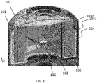
- FIG 1 illustrates a 3D cross section of an upper part of an embodiment of the humidifier 100.
- a water tank 104 is present inside the humidifier 100 .
- a wick 101 is present inside the water tank 104 .
- the water tank 104 is hollow cylindrically shaped.
- the wick 101 is also hollow cylindrically shaped.
- the size of the wick 101 is adapted to the size of the water tank 104 such that the wick 101 can easily rotate inside the water tank 104.
- the wick 101 is connected or attached to the means for rotating the wick 102 which comprises blades 106.
- the connection 107 between the wick 101 and the means for rotating the wick 102 may be a plastic or a metal part or another material suitable for making this connection.
- the means for rotating the wick 102 is located inside the hollow part of the water tank 104 and inside the hollow part of the wick 101.
- the hollow part of the water tank 104 is located in an air flow path of the humidifier 100.
- the hollow part of the water tank 104 is part of the air flow channel inside the humidifier 100.
- blades 106 of the means for rotating the wick 102 are subjected to the air flow and will consequently start to rotate.
- the means for rotating the wick 102 is attached to the wick 101, the wick 101 will start to rotate inside the water tank 104.
- the disinfection unit contains two array of light sources 103a, 103b.
- the humidifier may also comprise one array of light sources.
- a first array of light sources 103a is located outside of the water tank 101 and positioned such that the outer surface of the wick 101 can be fully illuminated as the wick makes a 360 degrees rotation.
- the water tank is transparent to wavelengths emitted by the disinfection unit.
- the first array of light sources 103a is located on a support inside the humidifier for holding the water tank.
- the first array 103a may be located on an inner wall of the humidifier 100.
- the second array of light sources 103b is located inside the hollow part of the water tank 104 and the hollow part of the wick 101.
- the second array of light sources 103b is located on a support for the water tank 104.
- a part of the wick 101 is located outside of the water tank 104, indicated with arrow "Z".
- the air flow causes the means 102 for rotating the wick to rotate. While the wick 101 rotates, the air flow propagates through the part of the wick 101 sticking or located out of the water tank 104 such that the air gets humidified. The air flow also propagates through the part of the wick 101 that is located above water level in the water tank 104. The humidified air exits the humidifier 100 at the top of the humidifier 100.
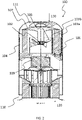
- FIG 2 illustrates a cross section of a humidifier 100.
- the upper part of the humidifier 100 is similar as illustrated in FIG 1 .
- the lower part of the humidifier 100 comprises a fan 109 for generating an air flow in the humidifier 100.
- the fan 109 ensures that air is sucked into the humidifier 100 via inlet 110 present at the bottom 120 of the humidifier 100, propagated through the humidifier 100 and exit the humidifier 100 at the outlet 111 present at the top 130 of the humidifier 100.
- the bottom 120 being defined as the part of the humidifier 100 that is used to rest on a surface in normal working mode.
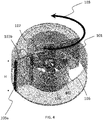
- FIG 3 illustrates how the air propagates through the humidifier 100.
- the arrows 105 illustrate the air being sucked into the humidifier 100, the air flow hits the wind blades 106 causing the wick 101 to rotate, the air flow passes through the wick 101 as the wick 101 rotates in the water tank 104 and finally the air exits the humidifier at the top 130 of the humidifier 100.
- height H of the wick 101 As also indicated in FIG 1 , height H of the wick 101.
- the height H of the wick is larger than the height of the water tank.
- the disinfection unit is located on an inner wall of the humidifier.
- the humidifier may comprise a support for holding the water tank.
- the disinfection unit may be located on this support for holding the water tank.
- the disinfection unit is located close to the water tank and the wick.
- the means for rotating the wick may rest on a support inside the humidifier.
- the support is adapted to allow the mechanical structure to rotate.
- the support may be attached to an inner wall of the humidifier.
- this support may comprise a ball bearing.
- the support may comprise an indentation whereby the means for rotating the wick comprises a bulge or a pin suitable for resting in the indentation and whereby the means for rotating the wick is capable of rotating when resting on the support.
- friction between the support and the means for rotating the wick should be minimal for allowing smooth rotation.
- the disinfection unit comprises an array of light emitting diodes (LEDs).
- the shape of the array may be elongated, wherein the direction of the elongated array is perpendicular to the direction in which the wick rotates when activated.
- LEDs light emitting diodes
- FIG 4 illustrates such an embodiment.
- Arrow 108 indicates the rotation direction of the wick 101.
- the wick 101 is hollow cylindrically shaped. Inside the hollow part of the wick 101 the means 102 for rotating the wick is located.
- the means 102 for rotating the wick comprises wind blades 106.
- the means 102 for rotating the wick 101 is fixedly coupled to the wick 101.
- a mechanism may be present which minimizes the force required to rotate the wick 101, e.g. a set of gears.
- Array of light sources 103a, 103b are located on both sides of the wick 101.
- a first array of light sources 103a is located on the outside of the wick 101 and a second array of light sources 103b is located inside the wick 101, namely, inside the hollow part of the wick 101.
- the direction of both the first 103a and the second 103b array of light sources are perpendicular to the rotation direction 108 of the wick.
- the height H (also illustrated in FIG1 , FIG 3 and FIG 4 ) of the array of light sources 103a, 103b is adapted to the height of the wick 101 such the complete wick 101 can be illuminated and thereby disinfected.
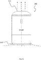
- FIG 5 illustrates a frontal view of an embodiment of a humidifier 100.
- the dotted-line arrows indicate the locations where air enters and exits the humidifier 100 when the fan inside the humidifier 100 is activated.
- FIG 6 illustrates a 3D line drawing of an embodiment of the humidifier 100.
Landscapes
- Engineering & Computer Science (AREA)
- Chemical & Material Sciences (AREA)
- Health & Medical Sciences (AREA)
- Combustion & Propulsion (AREA)
- Mechanical Engineering (AREA)
- General Engineering & Computer Science (AREA)
- Life Sciences & Earth Sciences (AREA)
- Epidemiology (AREA)
- Animal Behavior & Ethology (AREA)
- General Health & Medical Sciences (AREA)
- Public Health (AREA)
- Veterinary Medicine (AREA)
- Dispersion Chemistry (AREA)
- Chemical Kinetics & Catalysis (AREA)
- Air Humidification (AREA)
Claims (9)
- Humidificateur, comprenant:un ventilateur (109) pour générer un flux d'air;un réservoir d'eau cylindrique creux (104) ayant une partie creuse qui est située dans un trajet d'écoulement d'air de l'humidificateur;une mèche rotative cylindrique creuse (101) située au moins partiellement dans le réservoir d'eau (104);des pales de vent (106) situées dans le chemin d'écoulement d'air et qui sont destinées à convertir une force exercée par un écoulement d'air dans le chemin d'écoulement d'air sur les pales de vent en une force de rotation pour faire tourner la mèche (101); etune unité de désinfection comprenant au moins un réseau de sources de rayonnement électromagnétique (130a, 103b) situées de manière fixe à l'intérieur de l'humidificateur et adaptées de telle sorte que différentes parties de la mèche soient exposées au rayonnement de l'unité de désinfection et ainsi désinfectées lorsque la mèche tourne.
- Humidificateur selon la revendication 1, dans lequel le rayonnement de l'unité de désinfection est en outre dirigé vers le réservoir d'eau (104) pour désinfecter le contenu du réservoir d'eau.
- Humidificateur selon la revendication 2, dans lequel un premier élément (103a) de l'unité de désinfection est situé à l'extérieur du réservoir d'eau sur une surface extérieure du réservoir d'eau de sorte que la mèche, le réservoir d'eau et le contenu du réservoir d'eau sont désinfectés lorsqu'ils sont activés.
- Humidificateur selon la revendication 3, dans lequel un deuxième élément (103b) de l'unité de désinfection est situé au niveau d'une surface extérieure du réservoir d'eau à l'intérieur de la partie creuse du réservoir d'eau de sorte que la mèche, le réservoir d'eau et le contenu du réservoir d'eau sont désinfectés lorsqu'ils sont activés.
- Humidificateur selon l'une quelconque des revendications précédentes, dans lequel les pales de vent (106) sont situées à l'intérieur de la partie creuse de la mèche.
- Humidificateur selon l'une quelconque des revendications précédentes, dans lequel la mèche (101) est formée d'un matériau tel que la mèche flotte partiellement dans l'eau lorsqu'elle est immergée.
- Humidificateur selon l'une quelconque des revendications précédentes, dans lequel l'unité de désinfection comprend un réseau de diodes électroluminescentes.
- Humidificateur selon l'une quelconque des revendications précédentes, comprenant en outre un filtre à polluants atmosphériques situé en amont de la mèche.
- Humidificateur selon l'une quelconque des revendications précédentes, dans lequel les sources de rayonnement électromagnétique comprennent une ou plusieurs des sources suivantes: UVA, UVB ou UVC, source lumineuse de 405 nm ou IR.
Applications Claiming Priority (3)
| Application Number | Priority Date | Filing Date | Title |
|---|---|---|---|
| CN2017106002 | 2017-10-13 | ||
| EP18174776.7A EP3574926A1 (fr) | 2018-05-29 | 2018-05-29 | Humidificateur avec unité de désinfection |
| PCT/EP2018/076947 WO2019072668A1 (fr) | 2017-10-13 | 2018-10-04 | Humidificateur avec unité de désinfection |
Publications (2)
| Publication Number | Publication Date |
|---|---|
| EP3694563A1 EP3694563A1 (fr) | 2020-08-19 |
| EP3694563B1 true EP3694563B1 (fr) | 2022-09-07 |
Family
ID=63713905
Family Applications (1)
| Application Number | Title | Priority Date | Filing Date |
|---|---|---|---|
| EP18779690.9A Active EP3694563B1 (fr) | 2017-10-13 | 2018-10-04 | Humidificateur avec unité de désinfection |
Country Status (5)
| Country | Link |
|---|---|
| US (1) | US11235082B2 (fr) |
| EP (1) | EP3694563B1 (fr) |
| CN (1) | CN111212665B (fr) |
| PL (1) | PL3694563T3 (fr) |
| WO (1) | WO2019072668A1 (fr) |
Families Citing this family (3)
| Publication number | Priority date | Publication date | Assignee | Title |
|---|---|---|---|---|
| DE102020003357B4 (de) | 2020-06-03 | 2024-06-27 | SDT Industrial Technology UG (haftungsbeschränkt) | Die Vorrichtung zur Luft-Desinfektion |
| JP1676734S (fr) * | 2020-06-24 | 2021-01-18 | ||
| USD941978S1 (en) * | 2020-07-24 | 2022-01-25 | Shenzhen Yifei Technology Co., Ltd. | Humidifier |
Family Cites Families (20)
| Publication number | Priority date | Publication date | Assignee | Title |
|---|---|---|---|---|
| US3705479A (en) * | 1969-05-15 | 1972-12-12 | Wilson W Mcpherson | Apparatus for cooling air |
| GB2140912A (en) * | 1983-05-11 | 1984-12-05 | Colston James J F | Humidity controlling device |
| US5330722A (en) * | 1991-02-27 | 1994-07-19 | William E. Pick | Germicidal air filter |
| US6845971B2 (en) | 2001-06-18 | 2005-01-25 | Slant/Fin Corporation | Sterile humidifier and method of operating same |
| US7513486B2 (en) | 2004-05-24 | 2009-04-07 | Kaz, Inc. | Humidifier with improved UV disinfection |
| JP2005344979A (ja) * | 2004-06-02 | 2005-12-15 | Hitachi Home & Life Solutions Inc | 加湿器 |
| US7362964B2 (en) * | 2006-04-07 | 2008-04-22 | Chi-Hsiang Wang | Humidifier with ultraviolet lamp |
| US8940085B2 (en) * | 2011-03-16 | 2015-01-27 | Access Business Group International Llc | Humidifier with ultraviolet disinfection |
| GB2500010B (en) * | 2012-03-06 | 2016-08-24 | Dyson Technology Ltd | A humidifying apparatus |
| CN104395676B (zh) | 2012-06-28 | 2018-02-02 | 皇家飞利浦有限公司 | 蒸发式加湿器及包括该蒸发式加湿器的室内气候控制系统 |
| KR20160038653A (ko) | 2014-09-30 | 2016-04-07 | 서울바이오시스 주식회사 | 자외선을 이용한 살균 가습기 |
| CN204388277U (zh) | 2014-12-08 | 2015-06-10 | 广东美的制冷设备有限公司 | 加湿器 |
| CN104676768B (zh) | 2015-01-31 | 2017-10-31 | 宁波欧琳环境科技有限公司 | 带加湿功能的空气净化器 |
| KR101669911B1 (ko) * | 2015-02-26 | 2016-10-27 | 엘지전자 주식회사 | 식수공급장치 |
| WO2016173205A1 (fr) * | 2015-04-30 | 2016-11-03 | 广东美的制冷设备有限公司 | Canal d'air de dispositif de purification et d'humidification d'air et dispositif de purification et d'humidification d'air comprenant celui-ci |
| CN204717854U (zh) * | 2015-04-30 | 2015-10-21 | 广东美的制冷设备有限公司 | 空气净化加湿设备的风道和空气净化加湿设备 |
| KR101718615B1 (ko) | 2015-07-23 | 2017-03-24 | (주)비케이더블유 | 기화식 가습기 |
| KR101973644B1 (ko) | 2015-10-30 | 2019-08-26 | 엘지전자 주식회사 | 가습청정장치 |
| KR20170090209A (ko) | 2016-01-28 | 2017-08-07 | 한국산업기술대학교산학협력단 | 공기 살균 유닛 및 이를 포함하는 공기 청정기 |
| CN205773669U (zh) * | 2016-01-29 | 2016-12-07 | 佛山市顺德区美的饮水机制造有限公司 | 净饮机 |
-
2018
- 2018-10-04 US US16/754,212 patent/US11235082B2/en active Active
- 2018-10-04 WO PCT/EP2018/076947 patent/WO2019072668A1/fr unknown
- 2018-10-04 PL PL18779690.9T patent/PL3694563T3/pl unknown
- 2018-10-04 CN CN201880066482.7A patent/CN111212665B/zh active Active
- 2018-10-04 EP EP18779690.9A patent/EP3694563B1/fr active Active
Also Published As
| Publication number | Publication date |
|---|---|
| US20210187150A1 (en) | 2021-06-24 |
| EP3694563A1 (fr) | 2020-08-19 |
| CN111212665B (zh) | 2022-09-30 |
| CN111212665A (zh) | 2020-05-29 |
| US11235082B2 (en) | 2022-02-01 |
| PL3694563T3 (pl) | 2023-01-02 |
| WO2019072668A1 (fr) | 2019-04-18 |
Similar Documents
| Publication | Publication Date | Title |
|---|---|---|
| EP3694563B1 (fr) | Humidificateur avec unité de désinfection | |
| US7513486B2 (en) | Humidifier with improved UV disinfection | |
| US20090173799A1 (en) | Volatile Liquid Emitting Device | |
| US8833366B2 (en) | Liquid-evaporate delivery device | |
| US7722708B2 (en) | Air purification apparatus and method | |
| JP2001314492A (ja) | 脱臭殺菌性ガス供給手段を具備する空調装置類 | |
| KR101676817B1 (ko) | 방사형 공간 살균기 | |
| KR20130025565A (ko) | 광고판이 구비된 공기 살균 정화기 | |
| EP1858561A1 (fr) | Appareil destine a la diffusion de liquide volatil | |
| JP7519305B2 (ja) | 施設内の小さな有機物を変性させる技術 | |
| KR101400930B1 (ko) | 자외선 발광 다이오드 모듈을 구비한 살균 가습기 및 이를 이용한 살균 방법 | |
| CN201558351U (zh) | 一种茶香机 | |
| EP3574926A1 (fr) | Humidificateur avec unité de désinfection | |
| CN205090506U (zh) | 空气处理装置 | |
| JP3154192U (ja) | 次亜塩素酸水を使用した除菌消臭超音波加湿器 | |
| KR101514138B1 (ko) | 소형 열풍기 | |
| JP4735637B2 (ja) | 空気調和機 | |
| KR200391740Y1 (ko) | 포충기능을 갖는 공기청정기 | |
| JP7189459B1 (ja) | 加湿装置 | |
| TW201929663A (zh) | 捕蟲器 | |
| JP4779146B2 (ja) | 脱臭装置 | |
| JP2007147278A (ja) | 空気調和機 | |
| KR101307359B1 (ko) | 레이저를 이용한 살균 및 악취제거방법 및 그 장치 | |
| JP4591458B2 (ja) | 空気調和機 | |
| CN117298302A (zh) | 一种通风管道内部循环消杀装置 |
Legal Events
| Date | Code | Title | Description |
|---|---|---|---|
| STAA | Information on the status of an ep patent application or granted ep patent |
Free format text: STATUS: UNKNOWN |
|
| STAA | Information on the status of an ep patent application or granted ep patent |
Free format text: STATUS: THE INTERNATIONAL PUBLICATION HAS BEEN MADE |
|
| PUAI | Public reference made under article 153(3) epc to a published international application that has entered the european phase |
Free format text: ORIGINAL CODE: 0009012 |
|
| STAA | Information on the status of an ep patent application or granted ep patent |
Free format text: STATUS: REQUEST FOR EXAMINATION WAS MADE |
|
| 17P | Request for examination filed |
Effective date: 20200513 |
|
| AK | Designated contracting states |
Kind code of ref document: A1 Designated state(s): AL AT BE BG CH CY CZ DE DK EE ES FI FR GB GR HR HU IE IS IT LI LT LU LV MC MK MT NL NO PL PT RO RS SE SI SK SM TR |
|
| AX | Request for extension of the european patent |
Extension state: BA ME |
|
| DAV | Request for validation of the european patent (deleted) | ||
| DAX | Request for extension of the european patent (deleted) | ||
| REG | Reference to a national code |
Ref country code: DE Ref legal event code: R079 Ref document number: 602018040401 Country of ref document: DE Free format text: PREVIOUS MAIN CLASS: A61L0002080000 Ipc: A61L0002100000 |
|
| GRAP | Despatch of communication of intention to grant a patent |
Free format text: ORIGINAL CODE: EPIDOSNIGR1 |
|
| STAA | Information on the status of an ep patent application or granted ep patent |
Free format text: STATUS: GRANT OF PATENT IS INTENDED |
|
| RIC1 | Information provided on ipc code assigned before grant |
Ipc: F24F 8/22 20210101ALI20220304BHEP Ipc: F24F 8/20 20210101ALI20220304BHEP Ipc: F24F 6/06 20060101ALI20220304BHEP Ipc: A61L 9/20 20060101ALI20220304BHEP Ipc: A61L 2/08 20060101ALI20220304BHEP Ipc: A61L 2/10 20060101AFI20220304BHEP |
|
| INTG | Intention to grant announced |
Effective date: 20220330 |
|
| GRAS | Grant fee paid |
Free format text: ORIGINAL CODE: EPIDOSNIGR3 |
|
| GRAA | (expected) grant |
Free format text: ORIGINAL CODE: 0009210 |
|
| STAA | Information on the status of an ep patent application or granted ep patent |
Free format text: STATUS: THE PATENT HAS BEEN GRANTED |
|
| AK | Designated contracting states |
Kind code of ref document: B1 Designated state(s): AL AT BE BG CH CY CZ DE DK EE ES FI FR GB GR HR HU IE IS IT LI LT LU LV MC MK MT NL NO PL PT RO RS SE SI SK SM TR |
|
| REG | Reference to a national code |
Ref country code: GB Ref legal event code: FG4D |
|
| REG | Reference to a national code |
Ref country code: CH Ref legal event code: EP Ref country code: AT Ref legal event code: REF Ref document number: 1516517 Country of ref document: AT Kind code of ref document: T Effective date: 20220915 |
|
| REG | Reference to a national code |
Ref country code: DE Ref legal event code: R096 Ref document number: 602018040401 Country of ref document: DE |
|
| REG | Reference to a national code |
Ref country code: IE Ref legal event code: FG4D |
|
| REG | Reference to a national code |
Ref country code: LT Ref legal event code: MG9D |
|
| REG | Reference to a national code |
Ref country code: NL Ref legal event code: MP Effective date: 20220907 |
|
| PG25 | Lapsed in a contracting state [announced via postgrant information from national office to epo] |
Ref country code: SE Free format text: LAPSE BECAUSE OF FAILURE TO SUBMIT A TRANSLATION OF THE DESCRIPTION OR TO PAY THE FEE WITHIN THE PRESCRIBED TIME-LIMIT Effective date: 20220907 Ref country code: RS Free format text: LAPSE BECAUSE OF FAILURE TO SUBMIT A TRANSLATION OF THE DESCRIPTION OR TO PAY THE FEE WITHIN THE PRESCRIBED TIME-LIMIT Effective date: 20220907 Ref country code: NO Free format text: LAPSE BECAUSE OF FAILURE TO SUBMIT A TRANSLATION OF THE DESCRIPTION OR TO PAY THE FEE WITHIN THE PRESCRIBED TIME-LIMIT Effective date: 20221207 Ref country code: LV Free format text: LAPSE BECAUSE OF FAILURE TO SUBMIT A TRANSLATION OF THE DESCRIPTION OR TO PAY THE FEE WITHIN THE PRESCRIBED TIME-LIMIT Effective date: 20220907 Ref country code: LT Free format text: LAPSE BECAUSE OF FAILURE TO SUBMIT A TRANSLATION OF THE DESCRIPTION OR TO PAY THE FEE WITHIN THE PRESCRIBED TIME-LIMIT Effective date: 20220907 Ref country code: FI Free format text: LAPSE BECAUSE OF FAILURE TO SUBMIT A TRANSLATION OF THE DESCRIPTION OR TO PAY THE FEE WITHIN THE PRESCRIBED TIME-LIMIT Effective date: 20220907 |
|
| REG | Reference to a national code |
Ref country code: AT Ref legal event code: MK05 Ref document number: 1516517 Country of ref document: AT Kind code of ref document: T Effective date: 20220907 |
|
| PG25 | Lapsed in a contracting state [announced via postgrant information from national office to epo] |
Ref country code: HR Free format text: LAPSE BECAUSE OF FAILURE TO SUBMIT A TRANSLATION OF THE DESCRIPTION OR TO PAY THE FEE WITHIN THE PRESCRIBED TIME-LIMIT Effective date: 20220907 Ref country code: GR Free format text: LAPSE BECAUSE OF FAILURE TO SUBMIT A TRANSLATION OF THE DESCRIPTION OR TO PAY THE FEE WITHIN THE PRESCRIBED TIME-LIMIT Effective date: 20221208 |
|
| PG25 | Lapsed in a contracting state [announced via postgrant information from national office to epo] |
Ref country code: SM Free format text: LAPSE BECAUSE OF FAILURE TO SUBMIT A TRANSLATION OF THE DESCRIPTION OR TO PAY THE FEE WITHIN THE PRESCRIBED TIME-LIMIT Effective date: 20220907 Ref country code: RO Free format text: LAPSE BECAUSE OF FAILURE TO SUBMIT A TRANSLATION OF THE DESCRIPTION OR TO PAY THE FEE WITHIN THE PRESCRIBED TIME-LIMIT Effective date: 20220907 Ref country code: PT Free format text: LAPSE BECAUSE OF FAILURE TO SUBMIT A TRANSLATION OF THE DESCRIPTION OR TO PAY THE FEE WITHIN THE PRESCRIBED TIME-LIMIT Effective date: 20230109 Ref country code: ES Free format text: LAPSE BECAUSE OF FAILURE TO SUBMIT A TRANSLATION OF THE DESCRIPTION OR TO PAY THE FEE WITHIN THE PRESCRIBED TIME-LIMIT Effective date: 20220907 Ref country code: CZ Free format text: LAPSE BECAUSE OF FAILURE TO SUBMIT A TRANSLATION OF THE DESCRIPTION OR TO PAY THE FEE WITHIN THE PRESCRIBED TIME-LIMIT Effective date: 20220907 Ref country code: AT Free format text: LAPSE BECAUSE OF FAILURE TO SUBMIT A TRANSLATION OF THE DESCRIPTION OR TO PAY THE FEE WITHIN THE PRESCRIBED TIME-LIMIT Effective date: 20220907 |
|
| PG25 | Lapsed in a contracting state [announced via postgrant information from national office to epo] |
Ref country code: SK Free format text: LAPSE BECAUSE OF FAILURE TO SUBMIT A TRANSLATION OF THE DESCRIPTION OR TO PAY THE FEE WITHIN THE PRESCRIBED TIME-LIMIT Effective date: 20220907 Ref country code: IS Free format text: LAPSE BECAUSE OF FAILURE TO SUBMIT A TRANSLATION OF THE DESCRIPTION OR TO PAY THE FEE WITHIN THE PRESCRIBED TIME-LIMIT Effective date: 20230107 Ref country code: EE Free format text: LAPSE BECAUSE OF FAILURE TO SUBMIT A TRANSLATION OF THE DESCRIPTION OR TO PAY THE FEE WITHIN THE PRESCRIBED TIME-LIMIT Effective date: 20220907 |
|
| REG | Reference to a national code |
Ref country code: CH Ref legal event code: PL |
|
| REG | Reference to a national code |
Ref country code: DE Ref legal event code: R097 Ref document number: 602018040401 Country of ref document: DE |
|
| REG | Reference to a national code |
Ref country code: BE Ref legal event code: MM Effective date: 20221031 |
|
| PG25 | Lapsed in a contracting state [announced via postgrant information from national office to epo] |
Ref country code: NL Free format text: LAPSE BECAUSE OF FAILURE TO SUBMIT A TRANSLATION OF THE DESCRIPTION OR TO PAY THE FEE WITHIN THE PRESCRIBED TIME-LIMIT Effective date: 20220907 Ref country code: MC Free format text: LAPSE BECAUSE OF FAILURE TO SUBMIT A TRANSLATION OF THE DESCRIPTION OR TO PAY THE FEE WITHIN THE PRESCRIBED TIME-LIMIT Effective date: 20220907 Ref country code: LU Free format text: LAPSE BECAUSE OF NON-PAYMENT OF DUE FEES Effective date: 20221004 Ref country code: AL Free format text: LAPSE BECAUSE OF FAILURE TO SUBMIT A TRANSLATION OF THE DESCRIPTION OR TO PAY THE FEE WITHIN THE PRESCRIBED TIME-LIMIT Effective date: 20220907 |
|
| P01 | Opt-out of the competence of the unified patent court (upc) registered |
Effective date: 20230530 |
|
| PLBE | No opposition filed within time limit |
Free format text: ORIGINAL CODE: 0009261 |
|
| STAA | Information on the status of an ep patent application or granted ep patent |
Free format text: STATUS: NO OPPOSITION FILED WITHIN TIME LIMIT |
|
| PG25 | Lapsed in a contracting state [announced via postgrant information from national office to epo] |
Ref country code: LI Free format text: LAPSE BECAUSE OF NON-PAYMENT OF DUE FEES Effective date: 20221031 Ref country code: DK Free format text: LAPSE BECAUSE OF FAILURE TO SUBMIT A TRANSLATION OF THE DESCRIPTION OR TO PAY THE FEE WITHIN THE PRESCRIBED TIME-LIMIT Effective date: 20220907 Ref country code: CH Free format text: LAPSE BECAUSE OF NON-PAYMENT OF DUE FEES Effective date: 20221031 |
|
| 26N | No opposition filed |
Effective date: 20230608 |
|
| PG25 | Lapsed in a contracting state [announced via postgrant information from national office to epo] |
Ref country code: SI Free format text: LAPSE BECAUSE OF FAILURE TO SUBMIT A TRANSLATION OF THE DESCRIPTION OR TO PAY THE FEE WITHIN THE PRESCRIBED TIME-LIMIT Effective date: 20220907 |
|
| PG25 | Lapsed in a contracting state [announced via postgrant information from national office to epo] |
Ref country code: BE Free format text: LAPSE BECAUSE OF NON-PAYMENT OF DUE FEES Effective date: 20221031 |
|
| PG25 | Lapsed in a contracting state [announced via postgrant information from national office to epo] |
Ref country code: IE Free format text: LAPSE BECAUSE OF NON-PAYMENT OF DUE FEES Effective date: 20221004 |
|
| PGFP | Annual fee paid to national office [announced via postgrant information from national office to epo] |
Ref country code: PL Payment date: 20230927 Year of fee payment: 6 |
|
| REG | Reference to a national code |
Ref country code: DE Ref legal event code: R081 Ref document number: 602018040401 Country of ref document: DE Owner name: VERSUNI HOLDING B.V., NL Free format text: FORMER OWNER: KONINKLIJKE PHILIPS N.V., EINDHOVEN, NL |
|
| REG | Reference to a national code |
Ref country code: GB Ref legal event code: 732E Free format text: REGISTERED BETWEEN 20231214 AND 20231220 |
|
| PGFP | Annual fee paid to national office [announced via postgrant information from national office to epo] |
Ref country code: GB Payment date: 20231024 Year of fee payment: 6 |
|
| PGFP | Annual fee paid to national office [announced via postgrant information from national office to epo] |
Ref country code: FR Payment date: 20231026 Year of fee payment: 6 Ref country code: DE Payment date: 20231027 Year of fee payment: 6 |
|
| PG25 | Lapsed in a contracting state [announced via postgrant information from national office to epo] |
Ref country code: CY Free format text: LAPSE BECAUSE OF FAILURE TO SUBMIT A TRANSLATION OF THE DESCRIPTION OR TO PAY THE FEE WITHIN THE PRESCRIBED TIME-LIMIT Effective date: 20220907 |
|
| PG25 | Lapsed in a contracting state [announced via postgrant information from national office to epo] |
Ref country code: MK Free format text: LAPSE BECAUSE OF FAILURE TO SUBMIT A TRANSLATION OF THE DESCRIPTION OR TO PAY THE FEE WITHIN THE PRESCRIBED TIME-LIMIT Effective date: 20220907 Ref country code: IT Free format text: LAPSE BECAUSE OF FAILURE TO SUBMIT A TRANSLATION OF THE DESCRIPTION OR TO PAY THE FEE WITHIN THE PRESCRIBED TIME-LIMIT Effective date: 20220907 Ref country code: HU Free format text: LAPSE BECAUSE OF FAILURE TO SUBMIT A TRANSLATION OF THE DESCRIPTION OR TO PAY THE FEE WITHIN THE PRESCRIBED TIME-LIMIT; INVALID AB INITIO Effective date: 20181004 |
|
| PG25 | Lapsed in a contracting state [announced via postgrant information from national office to epo] |
Ref country code: BG Free format text: LAPSE BECAUSE OF FAILURE TO SUBMIT A TRANSLATION OF THE DESCRIPTION OR TO PAY THE FEE WITHIN THE PRESCRIBED TIME-LIMIT Effective date: 20220907 |
|
| PG25 | Lapsed in a contracting state [announced via postgrant information from national office to epo] |
Ref country code: MT Free format text: LAPSE BECAUSE OF FAILURE TO SUBMIT A TRANSLATION OF THE DESCRIPTION OR TO PAY THE FEE WITHIN THE PRESCRIBED TIME-LIMIT Effective date: 20220907 |