EP3693951A1 - Bonding device and bonding method for special-shaped curved cover plate and flexible screen - Google Patents
Bonding device and bonding method for special-shaped curved cover plate and flexible screen Download PDFInfo
- Publication number
- EP3693951A1 EP3693951A1 EP18914970.1A EP18914970A EP3693951A1 EP 3693951 A1 EP3693951 A1 EP 3693951A1 EP 18914970 A EP18914970 A EP 18914970A EP 3693951 A1 EP3693951 A1 EP 3693951A1
- Authority
- EP
- European Patent Office
- Prior art keywords
- bonding
- abutting
- wall
- cover plate
- irregular shape
- Prior art date
- Legal status (The legal status is an assumption and is not a legal conclusion. Google has not performed a legal analysis and makes no representation as to the accuracy of the status listed.)
- Granted
Links
Images


Classifications
-
- B—PERFORMING OPERATIONS; TRANSPORTING
- B32—LAYERED PRODUCTS
- B32B—LAYERED PRODUCTS, i.e. PRODUCTS BUILT-UP OF STRATA OF FLAT OR NON-FLAT, e.g. CELLULAR OR HONEYCOMB, FORM
- B32B41/00—Arrangements for controlling or monitoring lamination processes; Safety arrangements
-
- B—PERFORMING OPERATIONS; TRANSPORTING
- B32—LAYERED PRODUCTS
- B32B—LAYERED PRODUCTS, i.e. PRODUCTS BUILT-UP OF STRATA OF FLAT OR NON-FLAT, e.g. CELLULAR OR HONEYCOMB, FORM
- B32B37/00—Methods or apparatus for laminating, e.g. by curing or by ultrasonic bonding
- B32B37/12—Methods or apparatus for laminating, e.g. by curing or by ultrasonic bonding characterised by using adhesives
- B32B37/1284—Application of adhesive
-
- B—PERFORMING OPERATIONS; TRANSPORTING
- B29—WORKING OF PLASTICS; WORKING OF SUBSTANCES IN A PLASTIC STATE IN GENERAL
- B29C—SHAPING OR JOINING OF PLASTICS; SHAPING OF MATERIAL IN A PLASTIC STATE, NOT OTHERWISE PROVIDED FOR; AFTER-TREATMENT OF THE SHAPED PRODUCTS, e.g. REPAIRING
- B29C63/00—Lining or sheathing, i.e. applying preformed layers or sheathings of plastics; Apparatus therefor
- B29C63/02—Lining or sheathing, i.e. applying preformed layers or sheathings of plastics; Apparatus therefor using sheet or web-like material
- B29C63/04—Lining or sheathing, i.e. applying preformed layers or sheathings of plastics; Apparatus therefor using sheet or web-like material by folding, winding, bending or the like
-
- B—PERFORMING OPERATIONS; TRANSPORTING
- B29—WORKING OF PLASTICS; WORKING OF SUBSTANCES IN A PLASTIC STATE IN GENERAL
- B29C—SHAPING OR JOINING OF PLASTICS; SHAPING OF MATERIAL IN A PLASTIC STATE, NOT OTHERWISE PROVIDED FOR; AFTER-TREATMENT OF THE SHAPED PRODUCTS, e.g. REPAIRING
- B29C65/00—Joining or sealing of preformed parts, e.g. welding of plastics materials; Apparatus therefor
- B29C65/48—Joining or sealing of preformed parts, e.g. welding of plastics materials; Apparatus therefor using adhesives, i.e. using supplementary joining material; solvent bonding
-
- B—PERFORMING OPERATIONS; TRANSPORTING
- B29—WORKING OF PLASTICS; WORKING OF SUBSTANCES IN A PLASTIC STATE IN GENERAL
- B29C—SHAPING OR JOINING OF PLASTICS; SHAPING OF MATERIAL IN A PLASTIC STATE, NOT OTHERWISE PROVIDED FOR; AFTER-TREATMENT OF THE SHAPED PRODUCTS, e.g. REPAIRING
- B29C66/00—General aspects of processes or apparatus for joining preformed parts
- B29C66/01—General aspects dealing with the joint area or with the area to be joined
- B29C66/05—Particular design of joint configurations
- B29C66/10—Particular design of joint configurations particular design of the joint cross-sections
- B29C66/11—Joint cross-sections comprising a single joint-segment, i.e. one of the parts to be joined comprising a single joint-segment in the joint cross-section
- B29C66/112—Single lapped joints
- B29C66/1122—Single lap to lap joints, i.e. overlap joints
-
- B—PERFORMING OPERATIONS; TRANSPORTING
- B29—WORKING OF PLASTICS; WORKING OF SUBSTANCES IN A PLASTIC STATE IN GENERAL
- B29C—SHAPING OR JOINING OF PLASTICS; SHAPING OF MATERIAL IN A PLASTIC STATE, NOT OTHERWISE PROVIDED FOR; AFTER-TREATMENT OF THE SHAPED PRODUCTS, e.g. REPAIRING
- B29C66/00—General aspects of processes or apparatus for joining preformed parts
- B29C66/50—General aspects of joining tubular articles; General aspects of joining long products, i.e. bars or profiled elements; General aspects of joining single elements to tubular articles, hollow articles or bars; General aspects of joining several hollow-preforms to form hollow or tubular articles
- B29C66/51—Joining tubular articles, profiled elements or bars; Joining single elements to tubular articles, hollow articles or bars; Joining several hollow-preforms to form hollow or tubular articles
- B29C66/53—Joining single elements to tubular articles, hollow articles or bars
- B29C66/532—Joining single elements to the wall of tubular articles, hollow articles or bars
- B29C66/5326—Joining single elements to the wall of tubular articles, hollow articles or bars said single elements being substantially flat
-
- B—PERFORMING OPERATIONS; TRANSPORTING
- B29—WORKING OF PLASTICS; WORKING OF SUBSTANCES IN A PLASTIC STATE IN GENERAL
- B29C—SHAPING OR JOINING OF PLASTICS; SHAPING OF MATERIAL IN A PLASTIC STATE, NOT OTHERWISE PROVIDED FOR; AFTER-TREATMENT OF THE SHAPED PRODUCTS, e.g. REPAIRING
- B29C66/00—General aspects of processes or apparatus for joining preformed parts
- B29C66/70—General aspects of processes or apparatus for joining preformed parts characterised by the composition, physical properties or the structure of the material of the parts to be joined; Joining with non-plastics material
- B29C66/73—General aspects of processes or apparatus for joining preformed parts characterised by the composition, physical properties or the structure of the material of the parts to be joined; Joining with non-plastics material characterised by the intensive physical properties of the material of the parts to be joined, by the optical properties of the material of the parts to be joined, by the extensive physical properties of the parts to be joined, by the state of the material of the parts to be joined or by the material of the parts to be joined being a thermoplastic or a thermoset
- B29C66/733—General aspects of processes or apparatus for joining preformed parts characterised by the composition, physical properties or the structure of the material of the parts to be joined; Joining with non-plastics material characterised by the intensive physical properties of the material of the parts to be joined, by the optical properties of the material of the parts to be joined, by the extensive physical properties of the parts to be joined, by the state of the material of the parts to be joined or by the material of the parts to be joined being a thermoplastic or a thermoset characterised by the optical properties of the material of the parts to be joined, e.g. fluorescence, phosphorescence
- B29C66/7336—General aspects of processes or apparatus for joining preformed parts characterised by the composition, physical properties or the structure of the material of the parts to be joined; Joining with non-plastics material characterised by the intensive physical properties of the material of the parts to be joined, by the optical properties of the material of the parts to be joined, by the extensive physical properties of the parts to be joined, by the state of the material of the parts to be joined or by the material of the parts to be joined being a thermoplastic or a thermoset characterised by the optical properties of the material of the parts to be joined, e.g. fluorescence, phosphorescence at least one of the parts to be joined being opaque, transparent or translucent to visible light
- B29C66/73365—General aspects of processes or apparatus for joining preformed parts characterised by the composition, physical properties or the structure of the material of the parts to be joined; Joining with non-plastics material characterised by the intensive physical properties of the material of the parts to be joined, by the optical properties of the material of the parts to be joined, by the extensive physical properties of the parts to be joined, by the state of the material of the parts to be joined or by the material of the parts to be joined being a thermoplastic or a thermoset characterised by the optical properties of the material of the parts to be joined, e.g. fluorescence, phosphorescence at least one of the parts to be joined being opaque, transparent or translucent to visible light at least one of the parts to be joined being transparent or translucent to visible light
- B29C66/73366—General aspects of processes or apparatus for joining preformed parts characterised by the composition, physical properties or the structure of the material of the parts to be joined; Joining with non-plastics material characterised by the intensive physical properties of the material of the parts to be joined, by the optical properties of the material of the parts to be joined, by the extensive physical properties of the parts to be joined, by the state of the material of the parts to be joined or by the material of the parts to be joined being a thermoplastic or a thermoset characterised by the optical properties of the material of the parts to be joined, e.g. fluorescence, phosphorescence at least one of the parts to be joined being opaque, transparent or translucent to visible light at least one of the parts to be joined being transparent or translucent to visible light both parts to be joined being transparent or translucent to visible light
-
- B—PERFORMING OPERATIONS; TRANSPORTING
- B29—WORKING OF PLASTICS; WORKING OF SUBSTANCES IN A PLASTIC STATE IN GENERAL
- B29C—SHAPING OR JOINING OF PLASTICS; SHAPING OF MATERIAL IN A PLASTIC STATE, NOT OTHERWISE PROVIDED FOR; AFTER-TREATMENT OF THE SHAPED PRODUCTS, e.g. REPAIRING
- B29C66/00—General aspects of processes or apparatus for joining preformed parts
- B29C66/80—General aspects of machine operations or constructions and parts thereof
- B29C66/82—Pressure application arrangements, e.g. transmission or actuating mechanisms for joining tools or clamps
- B29C66/822—Transmission mechanisms
- B29C66/8226—Cam mechanisms; Wedges; Eccentric mechanisms
-
- B—PERFORMING OPERATIONS; TRANSPORTING
- B29—WORKING OF PLASTICS; WORKING OF SUBSTANCES IN A PLASTIC STATE IN GENERAL
- B29C—SHAPING OR JOINING OF PLASTICS; SHAPING OF MATERIAL IN A PLASTIC STATE, NOT OTHERWISE PROVIDED FOR; AFTER-TREATMENT OF THE SHAPED PRODUCTS, e.g. REPAIRING
- B29C66/00—General aspects of processes or apparatus for joining preformed parts
- B29C66/80—General aspects of machine operations or constructions and parts thereof
- B29C66/83—General aspects of machine operations or constructions and parts thereof characterised by the movement of the joining or pressing tools
- B29C66/832—Reciprocating joining or pressing tools
- B29C66/8322—Joining or pressing tools reciprocating along one axis
-
- B—PERFORMING OPERATIONS; TRANSPORTING
- B29—WORKING OF PLASTICS; WORKING OF SUBSTANCES IN A PLASTIC STATE IN GENERAL
- B29C—SHAPING OR JOINING OF PLASTICS; SHAPING OF MATERIAL IN A PLASTIC STATE, NOT OTHERWISE PROVIDED FOR; AFTER-TREATMENT OF THE SHAPED PRODUCTS, e.g. REPAIRING
- B29C66/00—General aspects of processes or apparatus for joining preformed parts
- B29C66/80—General aspects of machine operations or constructions and parts thereof
- B29C66/84—Specific machine types or machines suitable for specific applications
- B29C66/861—Hand-held tools
-
- B—PERFORMING OPERATIONS; TRANSPORTING
- B30—PRESSES
- B30B—PRESSES IN GENERAL
- B30B1/00—Presses, using a press ram, characterised by the features of the drive therefor, pressure being transmitted directly, or through simple thrust or tension members only, to the press ram or platen
- B30B1/40—Presses, using a press ram, characterised by the features of the drive therefor, pressure being transmitted directly, or through simple thrust or tension members only, to the press ram or platen by wedge means
-
- B—PERFORMING OPERATIONS; TRANSPORTING
- B30—PRESSES
- B30B—PRESSES IN GENERAL
- B30B7/00—Presses characterised by a particular arrangement of the pressing members
- B30B7/04—Presses characterised by a particular arrangement of the pressing members wherein pressing is effected in different directions simultaneously or in turn
-
- B—PERFORMING OPERATIONS; TRANSPORTING
- B32—LAYERED PRODUCTS
- B32B—LAYERED PRODUCTS, i.e. PRODUCTS BUILT-UP OF STRATA OF FLAT OR NON-FLAT, e.g. CELLULAR OR HONEYCOMB, FORM
- B32B37/00—Methods or apparatus for laminating, e.g. by curing or by ultrasonic bonding
- B32B37/0007—Methods or apparatus for laminating, e.g. by curing or by ultrasonic bonding involving treatment or provisions in order to avoid deformation or air inclusion, e.g. to improve surface quality
- B32B37/003—Methods or apparatus for laminating, e.g. by curing or by ultrasonic bonding involving treatment or provisions in order to avoid deformation or air inclusion, e.g. to improve surface quality to avoid air inclusion
-
- B—PERFORMING OPERATIONS; TRANSPORTING
- B32—LAYERED PRODUCTS
- B32B—LAYERED PRODUCTS, i.e. PRODUCTS BUILT-UP OF STRATA OF FLAT OR NON-FLAT, e.g. CELLULAR OR HONEYCOMB, FORM
- B32B37/00—Methods or apparatus for laminating, e.g. by curing or by ultrasonic bonding
- B32B37/0046—Methods or apparatus for laminating, e.g. by curing or by ultrasonic bonding characterised by constructional aspects of the apparatus
-
- B—PERFORMING OPERATIONS; TRANSPORTING
- B32—LAYERED PRODUCTS
- B32B—LAYERED PRODUCTS, i.e. PRODUCTS BUILT-UP OF STRATA OF FLAT OR NON-FLAT, e.g. CELLULAR OR HONEYCOMB, FORM
- B32B38/00—Ancillary operations in connection with laminating processes
- B32B38/18—Handling of layers or the laminate
- B32B38/1825—Handling of layers or the laminate characterised by the control or constructional features of devices for tensioning, stretching or registration
- B32B38/1833—Positioning, e.g. registration or centering
- B32B38/1841—Positioning, e.g. registration or centering during laying up
-
- B—PERFORMING OPERATIONS; TRANSPORTING
- B32—LAYERED PRODUCTS
- B32B—LAYERED PRODUCTS, i.e. PRODUCTS BUILT-UP OF STRATA OF FLAT OR NON-FLAT, e.g. CELLULAR OR HONEYCOMB, FORM
- B32B38/00—Ancillary operations in connection with laminating processes
- B32B38/18—Handling of layers or the laminate
- B32B38/1858—Handling of layers or the laminate using vacuum
-
- B—PERFORMING OPERATIONS; TRANSPORTING
- B32—LAYERED PRODUCTS
- B32B—LAYERED PRODUCTS, i.e. PRODUCTS BUILT-UP OF STRATA OF FLAT OR NON-FLAT, e.g. CELLULAR OR HONEYCOMB, FORM
- B32B38/00—Ancillary operations in connection with laminating processes
- B32B38/18—Handling of layers or the laminate
- B32B38/1866—Handling of layers or the laminate conforming the layers or laminate to a convex or concave profile
-
- G—PHYSICS
- G06—COMPUTING OR CALCULATING; COUNTING
- G06F—ELECTRIC DIGITAL DATA PROCESSING
- G06F1/00—Details not covered by groups G06F3/00 - G06F13/00 and G06F21/00
- G06F1/16—Constructional details or arrangements
- G06F1/1613—Constructional details or arrangements for portable computers
- G06F1/1633—Constructional details or arrangements of portable computers not specific to the type of enclosures covered by groups G06F1/1615 - G06F1/1626
- G06F1/1637—Details related to the display arrangement, including those related to the mounting of the display in the housing
- G06F1/1652—Details related to the display arrangement, including those related to the mounting of the display in the housing the display being flexible, e.g. mimicking a sheet of paper, or rollable
-
- G—PHYSICS
- G09—EDUCATION; CRYPTOGRAPHY; DISPLAY; ADVERTISING; SEALS
- G09F—DISPLAYING; ADVERTISING; SIGNS; LABELS OR NAME-PLATES; SEALS
- G09F9/00—Indicating arrangements for variable information in which the information is built-up on a support by selection or combination of individual elements
- G09F9/30—Indicating arrangements for variable information in which the information is built-up on a support by selection or combination of individual elements in which the desired character or characters are formed by combining individual elements
- G09F9/301—Indicating arrangements for variable information in which the information is built-up on a support by selection or combination of individual elements in which the desired character or characters are formed by combining individual elements flexible foldable or roll-able electronic displays, e.g. thin LCD, OLED
-
- B—PERFORMING OPERATIONS; TRANSPORTING
- B29—WORKING OF PLASTICS; WORKING OF SUBSTANCES IN A PLASTIC STATE IN GENERAL
- B29L—INDEXING SCHEME ASSOCIATED WITH SUBCLASS B29C, RELATING TO PARTICULAR ARTICLES
- B29L2031/00—Other particular articles
- B29L2031/34—Electrical apparatus, e.g. sparking plugs or parts thereof
- B29L2031/3475—Displays, monitors, TV-sets, computer screens
-
- B—PERFORMING OPERATIONS; TRANSPORTING
- B32—LAYERED PRODUCTS
- B32B—LAYERED PRODUCTS, i.e. PRODUCTS BUILT-UP OF STRATA OF FLAT OR NON-FLAT, e.g. CELLULAR OR HONEYCOMB, FORM
- B32B2457/00—Electrical equipment
- B32B2457/20—Displays, e.g. liquid crystal displays, plasma displays
-
- B—PERFORMING OPERATIONS; TRANSPORTING
- B32—LAYERED PRODUCTS
- B32B—LAYERED PRODUCTS, i.e. PRODUCTS BUILT-UP OF STRATA OF FLAT OR NON-FLAT, e.g. CELLULAR OR HONEYCOMB, FORM
- B32B37/00—Methods or apparatus for laminating, e.g. by curing or by ultrasonic bonding
- B32B37/12—Methods or apparatus for laminating, e.g. by curing or by ultrasonic bonding characterised by using adhesives
-
- G—PHYSICS
- G02—OPTICS
- G02F—OPTICAL DEVICES OR ARRANGEMENTS FOR THE CONTROL OF LIGHT BY MODIFICATION OF THE OPTICAL PROPERTIES OF THE MEDIA OF THE ELEMENTS INVOLVED THEREIN; NON-LINEAR OPTICS; FREQUENCY-CHANGING OF LIGHT; OPTICAL LOGIC ELEMENTS; OPTICAL ANALOGUE/DIGITAL CONVERTERS
- G02F1/00—Devices or arrangements for the control of the intensity, colour, phase, polarisation or direction of light arriving from an independent light source, e.g. switching, gating or modulating; Non-linear optics
- G02F1/01—Devices or arrangements for the control of the intensity, colour, phase, polarisation or direction of light arriving from an independent light source, e.g. switching, gating or modulating; Non-linear optics for the control of the intensity, phase, polarisation or colour
- G02F1/13—Devices or arrangements for the control of the intensity, colour, phase, polarisation or direction of light arriving from an independent light source, e.g. switching, gating or modulating; Non-linear optics for the control of the intensity, phase, polarisation or colour based on liquid crystals, e.g. single liquid crystal display cells
- G02F1/133—Constructional arrangements; Operation of liquid crystal cells; Circuit arrangements
- G02F1/1333—Constructional arrangements; Manufacturing methods
- G02F1/133354—Arrangements for aligning or assembling substrates
-
- G—PHYSICS
- G02—OPTICS
- G02F—OPTICAL DEVICES OR ARRANGEMENTS FOR THE CONTROL OF LIGHT BY MODIFICATION OF THE OPTICAL PROPERTIES OF THE MEDIA OF THE ELEMENTS INVOLVED THEREIN; NON-LINEAR OPTICS; FREQUENCY-CHANGING OF LIGHT; OPTICAL LOGIC ELEMENTS; OPTICAL ANALOGUE/DIGITAL CONVERTERS
- G02F2201/00—Constructional arrangements not provided for in groups G02F1/00 - G02F7/00
- G02F2201/56—Substrates having a particular shape, e.g. non-rectangular
-
- H—ELECTRICITY
- H10—SEMICONDUCTOR DEVICES; ELECTRIC SOLID-STATE DEVICES NOT OTHERWISE PROVIDED FOR
- H10K—ORGANIC ELECTRIC SOLID-STATE DEVICES
- H10K2102/00—Constructional details relating to the organic devices covered by this subclass
- H10K2102/301—Details of OLEDs
- H10K2102/311—Flexible OLED
-
- Y—GENERAL TAGGING OF NEW TECHNOLOGICAL DEVELOPMENTS; GENERAL TAGGING OF CROSS-SECTIONAL TECHNOLOGIES SPANNING OVER SEVERAL SECTIONS OF THE IPC; TECHNICAL SUBJECTS COVERED BY FORMER USPC CROSS-REFERENCE ART COLLECTIONS [XRACs] AND DIGESTS
- Y10—TECHNICAL SUBJECTS COVERED BY FORMER USPC
- Y10T—TECHNICAL SUBJECTS COVERED BY FORMER US CLASSIFICATION
- Y10T156/00—Adhesive bonding and miscellaneous chemical manufacture
- Y10T156/10—Methods of surface bonding and/or assembly therefor
- Y10T156/1002—Methods of surface bonding and/or assembly therefor with permanent bending or reshaping or surface deformation of self sustaining lamina
- Y10T156/1028—Methods of surface bonding and/or assembly therefor with permanent bending or reshaping or surface deformation of self sustaining lamina by bending, drawing or stretch forming sheet to assume shape of configured lamina while in contact therewith
Definitions
- the present disclosure relates to a technical field of flexible screen bonding, in particular to a bonding device and a bonding method for a curved cover plate with an irregular shape and a flexible screen.
- the flexible screen is a new growth point of the future industry, and the characteristic of flexibility of the flexible screen are continuously exploited and utilized. For example, by attaching the flexible screen to a 3D fixed curved cover plate (both sides of the cover plate are a quarter of arc), the display of the front and sides of the product can be realized.
- a conventional bonding method of the flexible screen is to abut the flexible onto the inner side of a glass cover plate via s silicon pad.
- a conventional bonding device can only perform bonding to the 3D fixed curved cover plate, when the cover plate is designed to be bent inwardly, that is, when the cover plate has an irregular shape, the bonding cannot be implemented by the conventional bonding device.
- a bonding device for a curved cover plate with an irregular shape and a flexible screen the curved cover plate with the irregular shape includes a flat area and arc hook areas located on both opposite sides of the flat area, and the arc hook areas smoothly transit with the flat area.
- the bonding device for the curved cover plate with the irregular shape and the flexible screen includes a first bonding half having a first abutting wall formed on a periphery thereof, the first abutting wall includes a first abutting curved wall and a first abutting flat wall, the first abutting curved wall matches with a shape of an inner surface of the arc hook area on one side of the curved cover plate with the irregular shape, and the first abutting flat wall smoothly transits with the first abutting curved wall; a second bonding half having a second abutting wall formed on a periphery thereof, the second abutting wall includes a second abutting curved wall and a second abutting flat wall, the second
- first bonding half and the second bonding half are symmetrically arranged.
- the bonding device for the curved cover plate with the irregular shape and the flexible screen further includes a positioning tool provided with a positioning groove configured to accommodate the curved cover plate with the irregular shape.
- first abutting curved wall is located on a first flange of the first bonding half extending away from the second bonding half; and the second abutting curved wall is located on a second flange of the second bonding half extending away from the first bonding half.
- the driving component includes a first plugging member and a second plugging member.
- the first bonding half has a first slot structurally matching with the first plugging member, and an extending direction of the first slot is inclined relative to a relative moving direction of the first bonding half and the second bonding half.
- the second bonding half has a second slot structurally matching with the second plugging member, and an extending direction of the second slot is inclined relative to the relative moving direction of the first bonding half and the second bonding half.
- the first plugging member is inserted into the first slot and movable along a direction perpendicular to the relative moving direction
- the second plugging member is inserted into the second slot and movable along the direction perpendicular to the moving direction, so as to drive the first bonding half and the second bonding half to switch between the closed position and the open position.
- first plugging member and the second plugging member are symmetrically arranged.
- an angle formed between the extending direction of the first slot and the extending direction of the second slot ranges from 45 degree to 60 degree.
- first plugging member is in clearance fit with the first slot
- second plugging member is in clearance fit with the second slot
- first plugging member and/or the second plugging member are telescopic.
- the driving component further includes a connecting member, the first plugging member and the second plugging member are mounted on the connecting member.
- the bonding device for the curved cover plate with the irregular shape and the flexible screen further includes a first telescopic cylinder configured to control the first plugging member and the second plugging member to move along the direction perpendicular to the relative moving direction.
- the connecting member is provided with a handle portion.
- first abutting wall and the second abutting wall are respectively provided with a plurality of vacuum adsorption holes.
- the driving component includes a second telescopic cylinder connected to the first bonding half and a third telescopic cylinder connected to the second bonding half, the second telescopic cylinder and the third telescopic cylinder are configured to drive the first bonding half and the second bonding half to move relative to each other.
- the bonding device for the curved cover plate with the irregular shape and the flexible screen further includes a power component configured to move the first bonding half and the second bonding half into an interior of the curved cover plate with the irregular shape or move the first bonding half and the second bonding half out of the interior of the curved cover plate with the irregular shape.
- the present disclosure further provides a method of bonding a curved cover plate with an irregular shape and a flexible screen using a bonding device for the curved cover plate with the irregular shape and the flexible screen.
- the bonding device includes a first bonding half, a second bonding half, and a driving component, the first bonding half includes a first abutting wall having a first abutting flat wall, the second bonding half includes a second abutting wall having a second abutting flat wall, the curved cover plate with the irregular shape includes a flat area and an arc hook area.
- the method includes:
- first abutting wall and the second abutting wall are respectively provided with a plurality of vacuum adsorption holes.
- the step of attaching the flexible screen to the first abutting wall and the second abutting wall includes: attaching the flexible screen to the first abutting wall and the second abutting wall via vacuum adsorption.
- the step of driving the driving component includes: reducing an attaching force between the flexible screen and the first abutting wall and the second abutting wall via reducing an adsorption pressure of the vacuum adsorption, thereby driving the driving component.
- the flexible screen or the curved cover plate with the irregular shape is attached with bonding adhesive layer configured to adhere the curved cover plate with the irregular shape and the flexible screen together.
- the first bonding half and the second bonding half have the first abutting flat wall and the second abutting flat wall used to abut the curved cover plate with the irregular shape, respectively, and have the first abutting curved wall and the second abutting curved wall used to abut the arc hook areas of the curved cover plate with the irregular shape, respectively.
- the first bonding half and the second bonding half are driven by the driving component to move to both sides respectively, different areas of the flexible screen are attached in different steps, thereby sufficiently attaching the arc hook area of the curved cover plate with the irregular shape and further improving the bonding effect.
- a bonding device 100 for a curved cover plate with an irregular shape and a flexible screen is used to bond a flexible screen 2 to an inner surface of a curved cover plate 3 with the irregular shape.
- the cover plate 3 with the irregular shape includes a flat area 31 with a planar shape, and arc hook areas 33 located on both opposite sides of the flat area 31, and the arc hook areas 33 smoothly transit with the flat area 31.
- the flat area 31 is located in a center position, and two arc hook areas 33 are formed by bending opposite sides of the flat area 31 inwardly, respectively.
- the arc hook areas 33 has a shape of semi-circular that is tangential to the flat area 31.
- the both opposite sides of the flat area 31 are virtual edges, which are also virtual boundaries between the flat area 31 and the arc hook areas 33.
- the bonding device 100 for the curved cover plate with the irregular shape and the flexible screen includes a first bonding half 110 having a first abutting flat wall 112 and a second bonding half 130 having a second abutting flat wall 132, which are adapted to abut an inner surface of the flexible screen, and a driving component 150 used to drive the first abutting flat wall 112 of the first bonding half 110 and the second abutting flat wall 132 of the second bonding half 130 to move relative to each other along the same plane.
- the first bonding half 110 has a first abutting wall 111 formed on a periphery thereof.
- the first abutting wall 111 includes a first abutting curved wall 114 matching with the shape of the inner surface of the arc hook area 33 on one side of the curved cover plate 3 with the irregular shape, and the first abutting flat wall 112 smoothly transiting with the first abutting curved wall 114, the first abutting flat wall 112 matches with the inner surface of the flat area 31 of the curved cover plate 3 with the irregular shape.
- the first abutting flat wall 112 is located on a bottom of the first bonding half 110, and is used to abut the flexible screen 2 onto the flat area 31 of the curved cover plate 3 with the irregular shape.
- the first abutting curved wall 114 is located at an end portion of the first bonding half 110 away from the second bonding half 130, and is used to abut an edge of the flexible screen 2 onto the inner surface of the arc hook area 33 of the curved cover plate 3 with the irregular shape.
- the first abutting flat wall 112 has a planar shape
- the first abutting curved wall 114 has a semi-circular shape matching with the inner surface of the arc acre 33.
- the first abutting curved wall 114 is located on a first flange (not labeled) of the first bonding half 110 extending away from the second bonding half 130. That is, after the first abutting curved wall 114 is attached to the flexible screen 2, the first abutting curved wall 114 can extend into the arc hook area 33, and allows the flexible screen 2 between the first abutting curved wall 114 and the arc hook area 33 to be precisely abutted onto the inner surface of the arc hook area 33. In other words, a difference between the radius of the inner surface of the arc hook area 33 and the radius of the first abutting curved wall 114 is the thickness of the flexible screen 2.
- the second bonding half 130 has a second abutting wall 131 on a periphery thereof.
- the second abutting wall 131 includes a second abutting curved wall 134 matching with the shape of the inner surface of the arc hook area 33 on another side of the curved cover plate 3 with the irregular shape, and a second abutting flat wall 132 smoothly transiting with the second abutting curved wall 134, the second abutting flat wall 132 matches with the inner surface of the flat area 31 of the curved cover plate 3 with the irregular shape.
- the second abutting flat wall 132 is located on the bottom of the second bonding half 130, and is used to abut the flexible screen 2 onto the flat area 31 of the curved cover plate 3 with the irregular shape.
- the second abutting curved wall 134 is located at an end of the second bonding half 130 away from the first bonding half 110, and is used to abut the edge of the flexible screen 2 onto the inner surface of the arc hook area 33 of the curved cover plate 3 with the irregular shape.
- the second abutting flat wall 132 has a planar shape
- the second abutting curved wall 134 has a semi-circular shape matching with the inner surface of the arc acre 33, that is, the structure of the second abutting curved wall 134 is the same as the structure of the first abutting curved wall 114, and the second abutting curved wall 134 and the first abutting curved wall 114 are arranged opposite to each other.
- the second abutting curved wall 134 is located on a second flange (not labeled) of the second bonding half 130 extending away from the first bonding half 110.
- the structures of the second abutting curved wall 134 and the first abutting curved wall 114 can be adjusted accordingly.
- the first bonding half 110 and the second bonding half 130 have a closed position where the first abutting flat wall 112 abuts against the second abutting flat wall 132 on the same plane, and an open position where the first abutting flat wall 112 and the second abutting flat wall 132 are separated from each other.
- the closed position the first abutting flat wall 112 and the second abutting flat wall 132 abut a middle portion of the flexible screen 2 onto the inner surface of the curved cover plate 3 with the irregular shape.
- the first abutting curved wall 114 and the second abutting curved wall 134 are adapted to abut edges of the flexible screen 2 onto the inner surfaces of the arc hook areas 33 of the curved cover plate 3 with the irregular shape.
- the driving component 150 is used to drive the first bonding half 110 and the second bonding half 130 to perform a relatively open movement or a relatively closed movement relative to each other on for example the same plane, such that the first bonding half 110 and the second bonding half 130 are in the closed position abutting against each other, or in the open position after moving to both sides of the curved cover plate with the irregular shape, respectively.
- the first abutting flat wall 112 and the second abutting flat wall 132 are adjacent to each other and located on the same plane.
- the flexible screen 2 are subjected to a pressure from the first abutting wall 111 and the second abutting wall 131 gradually form the middle portion to the edge portion at both right and left sides shown in the figures, such that the flexible screen 2 is sufficiently abutted onto the inner surfaces of the flat area 31 and the arc hook area 33 of the curved cover plate 3 with the irregular shape.
- the first abutting flat wall 112 and the second abutting flat wall 132 are both preferably rectangular.
- the side of the first abutting flat wall 112 coincides with the opposite side of the second abutting flat wall 132.
- the first abutting flat wall 112 and the first abutting curved wall 114 can be an integral surface
- the second abutting flat wall 132 and the second abutting curved wall 134 can also be an integral surface.
- first abutting flat wall 112 and the second abutting flat wall 132 are not limited to be rectangular.
- the sides of the first abutting flat wall 112 and the second abutting flat wall 132 that coincide with each other can be curved to match with each other.
- the other side of the first abutting flat wall 112 and the second abutting flat wall 132 adjacent to the coincident sides preferably extends over the edges of the curved cover plate 3 with the irregular shape, respectively.
- the overall distance between the first abutting flat wall 112 and the second abutting flat wall 132 along the left-right direction in FIG. 2 to FIG. 4 is less than the distance of the flat area 31 of the curved cover plate 3 with the irregular shape, such that the first bonding half 110 and the second bonding half 130 have space for moving to left and right sides.
- the bonding device in the closed position can be inserted into the interior of the curved cover plate 3 with the irregular shape through the opening of the curved cover plate 3 with the irregular shape during bonding the curved cover plate 3 with the irregular shape and the flexible screen 2.
- the first bonding half 110 and the second bonding half 130 are symmetrically arranged, so as to facilitate operation.
- the bonding device further includes a positioning tool 4.
- the positioning tool 4 is provided with a positioning groove 41 to accommodate the curved cover plate 3 with the irregular shape.
- the positioning groove 41 serves to position the curved cover plate 3 with the irregular shape and protect the curved cover plate 3 with the irregular shape from deformation under pressure.
- the driving component 150 includes a first plugging member 151 and a second plugging member 153.
- the first bonding half 110 has a first slot 113 structurally matching with the first plugging member 151, and an extending direction of the first slot 113 is inclined with respect to the relative moving direction (i.e., the left-right direction in the figures) of the first bonding half 110 and the second bonding half 130.
- the second bonding half 130 has a second slot 133 structurally matching with the second plugging member 153. An extending direction of the second slot 133 is inclined with respect to the relative moving direction of the first bonding half 110 and the second bonding half 130.
- the first plugging member 151 is adapted to be inserted into the first slot 113 and movable along a direction perpendicular to the relative moving direction, that is, the first plugging member 151 can move along the up-down direction in the figures.
- the second plugging member 153 is adapted to be inserted into the second slot 133 and movable along the direction perpendicular to the moving direction, so as to drive the first bonding half 110 and the second bonding half 130 to switch between the closed position and the open position.
- the first plugging member 151 is in clearance fit with the first slot 113, and the second plugging member 153is in clearance fit with the second slot 133.
- the first plugging member 151 and the second plugging member 153 are symmetrically arranged. In this way, the first plugging member 151 and the second plugging member 153 can be conveniently inserted into the first slot 113 and the second slot 133, respectively, so as to prevent the driving component 150 from not being inserted due to reversal.
- an extending line of the first plugging member 151 away from the first bonding half 110 intersects an extending line of the second plugging member 153 away from the second bonding half 130, so as to simplify the structure of the driving component 150.
- an angle formed by the extending direction of the first slot and the extending direction of the second slot ranges from 45 degree to 60 degree.
- the first plugging member 151 and the second plugging member 153 can attach to the first bonding half 110 and the second bonding half 130 by moving an appropriate distance.
- the driving component 150 occupies a less space along the left-right direction (that is, the relative moving direction of the first bonding half and the second bonding half).
- the driving component 150 further includes a connecting member 155.
- the first plugging member 151 and the second plugging member 153 are fixedly connected to the connecting member 155, that is, the end of the first plugging member 151 away from the first bonding half 110 is connected to the end of the second plugging member 153 away from the second bonding half 130 through the connecting member 155.
- the plugging members and the connecting member can be connected by a hinge, a detachable connection or the like.
- the upper end of the first plugging member 151 can be directly fixedly connected to the upper end of the second plugging member 153, or the relative fixing between the first plugging member 151 and the second plugging member 153 can be achieved by other means.
- the first bonding half 110 and the second bonding half 130 are driven to move towards the arc hook areas of the curved cover plate 3 with the irregular shape by the up and down moving of the driving component 150, respectively. Specifically, when the driving component 150 moves upward, the first bonding half 110 and the second bonding half 130 move to both sides, respectively; when the driving component 150 moves downward, the first bonding half 110 and the second bonding half 130 move towards the middle.
- the first bonding half 110 and the second bonding half 130 are in the closed state.
- the state in which the first plugging member 151 is fully inserted into the first slot 113, and the second plugging member 153 is fully inserted into the second slot 133 means that the first plugging member 151 cannot be inserted into the first slot 113 any further, and the second plugging member 153 cannot be inserted into the second slot 133 any further.
- the first bonding half 110 is bonded to the second bonding half 130
- the first plugging member 151 and the second plugging member 153 may not be completely inserted into the corresponding slots.
- the driving component 150 further includes a handle portion 157 relatively fixed to the connecting member 155. An operator can conveniently grasp the driving component 150 through the handle portion 157, so as to drive the driving component 150 to move up and down.
- the bonding device 100 further includes a first telescopic cylinder (not shown) used to control the driving component 150 to move up and down, which can effectively control the speed and time of the driving component 150 moving up and down, and save labor.
- the first telescopic cylinder can be a cylinder.
- the driving component 150 is not limited hereto, and can control the movements of the first bonding half 110 and the second bonding half 130 by other means, respectively.
- the first plugging member 151 and/or the second plugging member 153 can be arranged in a telescopic structure.
- the driving component 150 includes a second telescopic cylinder and a third telescopic cylinder, the second telescopic cylinder is connected to the first bonding half 110, the third telescopic cylinder connected to the second bonding half 130, and the second telescopic cylinder and the third telescopic cylinder drive the first bonding half 110 and the second bonding half 130 to move relative to each other.
- the second telescopic cylinder and the third telescopic cylinder can be cylinders, respectively.
- the first abutting wall 111 and the second abutting wall 131 are respectively provided with a plurality of vacuum adsorption holes (not shown), such that the flexible screen 2 can be attached to the first abutting wall 111 of the first bonding half 110 and the second abutting wall 131 of the second bonding half 130 by vacuum adsorption.
- the flexible screen 2 can be attached to the first bonding half 110 and the second bonding half 130 by other means.
- the left and right sides of the flexible screen 2 can both be adhered with flexible tapes, and other ends of the flexible tapes are fixed to the first bonding half 110 or the second bonding half 130 corresponding to the sides, respectively.
- the plurality of vacuum adsorption holes are not only provided on the first abutting wall 111 and the second abutting wall 131 of the first bonding half 110 and the second bonding half 130, but also provided on a side surface of the first bonding half 110 opposite to the first abutting flat wall 112 and adjacent to the first abutting curved wall 114, and provided on a side surface of the second bonding half 130 opposite to the second abutting flat wall 132 and adjacent to the second abutting curved wall 134.
- the flexible screen 2 can be fully attached to an absorption surface of the first bonding half 110 and the second bonding half 130 and have a flat C-shaped structure.
- first abutting flat wall 112 and the second abutting flat wall 132 have the same lengths in the first bonding half 110 and the second bonding half 130 along the left-right direction in the figures, so as to facilitate operation.
- first bonding half 110 and the second bonding half 130 have substantially the same structures and are symmetrically arranged.
- the bonding device 100 further includes a power component (not shown) used to move the first bonding half 110 and the second bonding half 130 into the interior of the curved cover plate 3 with the irregular shape or move the first bonding half 110 and the second bonding half 130 out of the interior of the curved cover plate 3 with the irregular shape.
- a power component (not shown) used to move the first bonding half 110 and the second bonding half 130 into the interior of the curved cover plate 3 with the irregular shape or move the first bonding half 110 and the second bonding half 130 out of the interior of the curved cover plate 3 with the irregular shape.
- the flexible screen 2 is attached to respective abutting walls of the first bonding half 110 and the second bonding half 130 outside the curved cover plate 3 with the irregular shape, then the first bonding half 110 and the second bonding half 130 enters the interior of the curved cover plate 3 with the irregular shape, so as to abut the flexible screen 2 to the inner surface of the curved cover plate 3 with the irregular shape.
- the first bonding half 110 and the second bonding half 130 have the first abutting flat wall 112 and the second abutting flat wall 132 used to abut the flat area 31 of the curved cover plate 3 with the irregular shape, respectively, and have the first abutting curved wall 114 and the second abutting curved wall 134 used to abut the arc hook areas 33 of the curved cover plate 3 with the irregular shape, respectively.
- the first bonding half 110 and the second bonding half 130 are driven by the driving component 150 to open along the left-right direction, different areas of the flexible screen 2 are gradually attached to the inner surface of the curved cover plate 3 with the irregular shape.
- the flexible screen 2 is gradually attached to the inner surface of the curved cover plate 3 with the irregular shape in an order from the middle to the left and right sides, thereby sufficiently attaching the arc hook areas 33 of the curved cover plate 3 with the irregular shape and further improving the bonding effect.
- the curved cover plate 3 with the irregular shape and the bonding device 110 can be easily separated by driving the first bonding half 110 and the second bonding half 130 to move towards each other along the left-right direction.
- the present disclosure further provides a method of bonding the curved cover plate 3 with an irregular shape and the flexible screen 2 using the bonding device for the curved cover plate 3 with the irregular shape and the flexible screen 2.
- the bonding device 100 includes the first bonding half 110, the second bonding half 130, and the driving component.
- the first bonding half 110 includes a first abutting wall 111 having a first abutting flat wall 112
- the second bonding half 130 includes a second abutting wall 131 having a second abutting flat wall 132.
- the curved cover plate 3 with the irregular shape includes a flat area 31 and an arc hook area 33.
- the method includes:
- the flexible screen 2 is preferably a flexible OLED screen. Of course, it should be noted that, the flexible screen 2 can be other flexible screens.
- step S1 it is firstly determined that the first abutting flat wall 112 of the first bonding half 110 is adjacent to the second abutting flat wall 132 of the second bonding half 130, that is, the bonding device 100 is in the closed state, so as to prevent the middle portion of the flexible screen 2 from being suspended, and the generating of bubbles during the attaching process is further avoided.
- the driving component is required to control the first bonding half 110 and the second bonding half 130 to move relative to each other, so as to make the bonding device 100 to be in the closed state.
- the flexible screen 2 and the curved cover plate 3 with the irregular shape can be adhered by a bonding adhesive layer.
- the bonding adhesive layer can be pre-attached onto the flexible screen 2, or be pre-attached onto the curved cover plate 3 with the irregular shape.
- the bonding adhesive layer is preferably an OCA layer, or the bonding adhesive layer can also be selected from other suitable adhesives.
- the step of attaching the flexible screen 2 onto the first abutting wall 111 and the second abutting wall 131 includes: attaching the flexible screen 2 to the first abutting wall 111 and the second abutting wall 131 by method of vacuum adsorption.
- the first abutting wall 111 and the second abutting wall 131 are both provided with a plurality of vacuum adsorption holes, and the flexible screen 2 is attached to the first bonding half 110 and the second bonding half 130 by vacuum adsorption.
- the adsorption pressure of the vacuum adsorption is -80 kpa.
- the step of driving the driving component includes: reducing an attaching force between the flexible screen 2 and the first bonding half 110 and first abutting wall 111, and the second bonding half 130 and the second abutting wall 131 by reducing the adsorption pressure of the vacuum adsorption, thereby driving the driving component.
- the adsorption pressure is -5 kpa to -20 kpa, more preferably, the adsorption pressure is -10 kpa.
- the arc hook areas 33 of the curved cover plate 3 with the irregular shape can be sufficiently attached, thereby further improving the bonding effect.
Landscapes
- Engineering & Computer Science (AREA)
- Mechanical Engineering (AREA)
- Theoretical Computer Science (AREA)
- Physics & Mathematics (AREA)
- General Physics & Mathematics (AREA)
- Computer Hardware Design (AREA)
- Quality & Reliability (AREA)
- Human Computer Interaction (AREA)
- General Engineering & Computer Science (AREA)
- Manufacturing & Machinery (AREA)
- Overhead Projectors And Projection Screens (AREA)
- Lining Or Joining Of Plastics Or The Like (AREA)
- Devices For Indicating Variable Information By Combining Individual Elements (AREA)
- Electroluminescent Light Sources (AREA)
- Chair Legs, Seat Parts, And Backrests (AREA)
- Laminated Bodies (AREA)
Abstract
Description
- The present disclosure relates to a technical field of flexible screen bonding, in particular to a bonding device and a bonding method for a curved cover plate with an irregular shape and a flexible screen.
- The flexible screen is a new growth point of the future industry, and the characteristic of flexibility of the flexible screen are continuously exploited and utilized. For example, by attaching the flexible screen to a 3D fixed curved cover plate (both sides of the cover plate are a quarter of arc), the display of the front and sides of the product can be realized.
- At present, a conventional bonding method of the flexible screen is to abut the flexible onto the inner side of a glass cover plate via s silicon pad.
- However, a conventional bonding device can only perform bonding to the 3D fixed curved cover plate, when the cover plate is designed to be bent inwardly, that is, when the cover plate has an irregular shape, the bonding cannot be implemented by the conventional bonding device.
- Accordingly, it is necessary to provide a new bonding device.
- A bonding device for a curved cover plate with an irregular shape and a flexible screen, the curved cover plate with the irregular shape includes a flat area and arc hook areas located on both opposite sides of the flat area, and the arc hook areas smoothly transit with the flat area. The bonding device for the curved cover plate with the irregular shape and the flexible screen includes a first bonding half having a first abutting wall formed on a periphery thereof, the first abutting wall includes a first abutting curved wall and a first abutting flat wall, the first abutting curved wall matches with a shape of an inner surface of the arc hook area on one side of the curved cover plate with the irregular shape, and the first abutting flat wall smoothly transits with the first abutting curved wall; a second bonding half having a second abutting wall formed on a periphery thereof, the second abutting wall includes a second abutting curved wall and a second abutting flat wall, the second abutting curved wall matches with a shape of an inner surface of the arc hook area on another side of the curved cover plate with the irregular shape, and the second abutting flat wall smoothly transits with the second abutting curved wall; the first bonding half and the second bonding half have a closed position where the first abutting flat wall and the second abutting flat wall abut on a same plane, and an open position where the first abutting flat wall and the second abutting flat wall are separated from each other; in the closed position, the first abutting flat wall and the second abutting flat wall abut a middle portion of the flexible screen onto an inner surface of the curved cover plate with the irregular shape; and in the open position, the first abutting curved wall and the second abutting curved wall abut edges of the flexible screen onto the inner surfaces of the arc hook areas of the curved cover plate with the irregular shape; and a driving component configured to drive the first bonding half and the second bonding half to move relative to each other, such that the first bonding half and the second bonding half switch between the closed position and the open position.
- In addition, the first bonding half and the second bonding half are symmetrically arranged.
- In addition, the bonding device for the curved cover plate with the irregular shape and the flexible screen further includes a positioning tool provided with a positioning groove configured to accommodate the curved cover plate with the irregular shape.
- In addition, the first abutting curved wall is located on a first flange of the first bonding half extending away from the second bonding half; and the second abutting curved wall is located on a second flange of the second bonding half extending away from the first bonding half.
- In addition, the driving component includes a first plugging member and a second plugging member. The first bonding half has a first slot structurally matching with the first plugging member, and an extending direction of the first slot is inclined relative to a relative moving direction of the first bonding half and the second bonding half. The second bonding half has a second slot structurally matching with the second plugging member, and an extending direction of the second slot is inclined relative to the relative moving direction of the first bonding half and the second bonding half. The first plugging member is inserted into the first slot and movable along a direction perpendicular to the relative moving direction, and the second plugging member is inserted into the second slot and movable along the direction perpendicular to the moving direction, so as to drive the first bonding half and the second bonding half to switch between the closed position and the open position.
- In addition, the first plugging member and the second plugging member are symmetrically arranged.
- In addition, an angle formed between the extending direction of the first slot and the extending direction of the second slot ranges from 45 degree to 60 degree.
- In addition, the first plugging member is in clearance fit with the first slot, and the second plugging member is in clearance fit with the second slot.
- In addition, the first plugging member and/or the second plugging member are telescopic.
- In addition, the driving component further includes a connecting member, the first plugging member and the second plugging member are mounted on the connecting member.
- In addition, the bonding device for the curved cover plate with the irregular shape and the flexible screen further includes a first telescopic cylinder configured to control the first plugging member and the second plugging member to move along the direction perpendicular to the relative moving direction.
- In addition, the connecting member is provided with a handle portion.
- In addition, the first abutting wall and the second abutting wall are respectively provided with a plurality of vacuum adsorption holes.
- In addition, the driving component includes a second telescopic cylinder connected to the first bonding half and a third telescopic cylinder connected to the second bonding half, the second telescopic cylinder and the third telescopic cylinder are configured to drive the first bonding half and the second bonding half to move relative to each other.
- In addition, the bonding device for the curved cover plate with the irregular shape and the flexible screen further includes a power component configured to move the first bonding half and the second bonding half into an interior of the curved cover plate with the irregular shape or move the first bonding half and the second bonding half out of the interior of the curved cover plate with the irregular shape.
- The present disclosure further provides a method of bonding a curved cover plate with an irregular shape and a flexible screen using a bonding device for the curved cover plate with the irregular shape and the flexible screen. The bonding device includes a first bonding half, a second bonding half, and a driving component, the first bonding half includes a first abutting wall having a first abutting flat wall, the second bonding half includes a second abutting wall having a second abutting flat wall, the curved cover plate with the irregular shape includes a flat area and an arc hook area. The method includes:
- closing the first bonding half and the second bonding half, and attaching the flexible screen to the first abutting wall and the second abutting wall, and obtaining an initial body;
- inserting the initial body into an interior of the curved cover plate with the irregular shape, abutting a middle portion of the flexible screen onto an inner surface of the flat area of the curved cover plate with the irregular shape via the first abutting flat wall and the second abutting flat wall, such that the first bonding half and the second bonding half is in a closed position; and
- driving the driving component, such that the first bonding half and the second bonding half move along a direction towards the arc hook area of the curved cover plate with the irregular shape and to an open position, respectively.
- In addition, the first abutting wall and the second abutting wall are respectively provided with a plurality of vacuum adsorption holes.
- The step of attaching the flexible screen to the first abutting wall and the second abutting wall includes: attaching the flexible screen to the first abutting wall and the second abutting wall via vacuum adsorption.
- The step of driving the driving component includes: reducing an attaching force between the flexible screen and the first abutting wall and the second abutting wall via reducing an adsorption pressure of the vacuum adsorption, thereby driving the driving component.
- In addition, the flexible screen or the curved cover plate with the irregular shape is attached with bonding adhesive layer configured to adhere the curved cover plate with the irregular shape and the flexible screen together.
- In the bonding device applied with the technical solution according to the present disclosure, the first bonding half and the second bonding half have the first abutting flat wall and the second abutting flat wall used to abut the curved cover plate with the irregular shape, respectively, and have the first abutting curved wall and the second abutting curved wall used to abut the arc hook areas of the curved cover plate with the irregular shape, respectively. The first bonding half and the second bonding half are driven by the driving component to move to both sides respectively, different areas of the flexible screen are attached in different steps, thereby sufficiently attaching the arc hook area of the curved cover plate with the irregular shape and further improving the bonding effect.
-
-
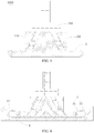
FIG. 1 is a cross-sectional view of a bonding device for a curved cover plate with an irregular shape and a flexible screen according to an embodiment of the present disclosure. -
FIG. 2 is a cross-sectional view of the bonding device ofFIG. 1 in a closed position. -
FIG. 3 is a cross-sectional view of an initial body formed by attaching a flexible screen to the bonding device ofFIG. 2 . -
FIG. 4 is a cross-sectional view of the preliminary abutting of the initial body ofFIG. 3 and a curved cover plate with an irregular shape. -
FIG. 5 is a cross-sectional view of completing abutting of the flexible screen and the curved cover plate with the irregular shape via the bonding device ofFIG. 1 . - Embodiments of the present disclosure are described more fully hereinafter with reference to the accompanying drawings, in which some embodiments of the present disclosure are shown. The various embodiments of the present disclosure may, however, be embodied in many different forms and should not be construed as limited to the embodiments set forth herein.
- It will be understood that when an element is referred to as being "fixed" to another element, it can be directly fixed to the other element or intervening elements may be present. Also, when an element is referred to as being "connected" or "coupled" to another element, it can be directly connected or coupled to the other element or intervening elements may be present. As used herein, the terms "vertical", "horizontal", "left", "right" and the like are merely for the illustrative purpose.
- Unless otherwise defined, all terms (including technical and scientific terms) used herein have the same meaning as commonly understood by one of ordinary skill in the art to which this invention belongs. The terms used herein is for the purpose of describing particular embodiments only and is not intended to limit the present disclosure. As used herein, the term "and/or" includes any and all combinations of one or more of the associated listed items.
- As shown in
FIG.1 to FIG. 5 , abonding device 100 for a curved cover plate with an irregular shape and a flexible screen is used to bond aflexible screen 2 to an inner surface of acurved cover plate 3 with the irregular shape. Thecover plate 3 with the irregular shape includes aflat area 31 with a planar shape, andarc hook areas 33 located on both opposite sides of theflat area 31, and thearc hook areas 33 smoothly transit with theflat area 31. In other words, theflat area 31 is located in a center position, and twoarc hook areas 33 are formed by bending opposite sides of theflat area 31 inwardly, respectively. Preferably, in the illustrated embodiment, thearc hook areas 33 has a shape of semi-circular that is tangential to theflat area 31. It should be noted that, in the illustrated embodiment, the both opposite sides of theflat area 31 are virtual edges, which are also virtual boundaries between theflat area 31 and thearc hook areas 33. - The
bonding device 100 for the curved cover plate with the irregular shape and the flexible screen includes afirst bonding half 110 having a first abuttingflat wall 112 and asecond bonding half 130 having a second abuttingflat wall 132, which are adapted to abut an inner surface of the flexible screen, and adriving component 150 used to drive the first abuttingflat wall 112 of the first bondinghalf 110 and the second abuttingflat wall 132 of the second bondinghalf 130 to move relative to each other along the same plane. - Specifically, the
first bonding half 110 has a firstabutting wall 111 formed on a periphery thereof. The first abuttingwall 111 includes a first abuttingcurved wall 114 matching with the shape of the inner surface of thearc hook area 33 on one side of thecurved cover plate 3 with the irregular shape, and the first abuttingflat wall 112 smoothly transiting with the first abuttingcurved wall 114, the first abuttingflat wall 112 matches with the inner surface of theflat area 31 of thecurved cover plate 3 with the irregular shape. Specifically, the first abuttingflat wall 112 is located on a bottom of thefirst bonding half 110, and is used to abut theflexible screen 2 onto theflat area 31 of thecurved cover plate 3 with the irregular shape. The first abuttingcurved wall 114 is located at an end portion of the first bondinghalf 110 away from the second bondinghalf 130, and is used to abut an edge of theflexible screen 2 onto the inner surface of thearc hook area 33 of thecurved cover plate 3 with the irregular shape. - In the illustrated embodiment, the first abutting
flat wall 112 has a planar shape, and the first abuttingcurved wall 114 has a semi-circular shape matching with the inner surface of thearc acre 33. Preferably, the first abuttingcurved wall 114 is located on a first flange (not labeled) of thefirst bonding half 110 extending away from thesecond bonding half 130. That is, after the first abuttingcurved wall 114 is attached to theflexible screen 2, the first abuttingcurved wall 114 can extend into thearc hook area 33, and allows theflexible screen 2 between the first abuttingcurved wall 114 and thearc hook area 33 to be precisely abutted onto the inner surface of thearc hook area 33. In other words, a difference between the radius of the inner surface of thearc hook area 33 and the radius of the first abuttingcurved wall 114 is the thickness of theflexible screen 2. - The
second bonding half 130 has a secondabutting wall 131 on a periphery thereof. The secondabutting wall 131 includes a second abuttingcurved wall 134 matching with the shape of the inner surface of thearc hook area 33 on another side of thecurved cover plate 3 with the irregular shape, and a second abuttingflat wall 132 smoothly transiting with the second abuttingcurved wall 134, the second abuttingflat wall 132 matches with the inner surface of theflat area 31 of thecurved cover plate 3 with the irregular shape. Specifically, the second abuttingflat wall 132 is located on the bottom of thesecond bonding half 130, and is used to abut theflexible screen 2 onto theflat area 31 of thecurved cover plate 3 with the irregular shape. The second abutting curvedwall 134 is located at an end of thesecond bonding half 130 away from thefirst bonding half 110, and is used to abut the edge of theflexible screen 2 onto the inner surface of thearc hook area 33 of thecurved cover plate 3 with the irregular shape. - In the illustrated embodiment, the second abutting
flat wall 132 has a planar shape, and the second abuttingcurved wall 134 has a semi-circular shape matching with the inner surface of thearc acre 33, that is, the structure of the second abuttingcurved wall 134 is the same as the structure of the first abuttingcurved wall 114, and the second abuttingcurved wall 134 and the first abuttingcurved wall 114 are arranged opposite to each other. Preferably, the second abuttingcurved wall 134 is located on a second flange (not labeled) of thesecond bonding half 130 extending away from thefirst bonding half 110. Of course, when thearc hook areas 33 on both sides of theflat area 31 has different structures, the structures of the second abuttingcurved wall 134 and the first abuttingcurved wall 114 can be adjusted accordingly. - The
first bonding half 110 and thesecond bonding half 130 have a closed position where the first abuttingflat wall 112 abuts against the second abuttingflat wall 132 on the same plane, and an open position where the first abuttingflat wall 112 and the second abuttingflat wall 132 are separated from each other. In the closed position, the first abuttingflat wall 112 and the second abuttingflat wall 132 abut a middle portion of theflexible screen 2 onto the inner surface of thecurved cover plate 3 with the irregular shape. In the open position, the first abuttingcurved wall 114 and the second abuttingcurved wall 134 are adapted to abut edges of theflexible screen 2 onto the inner surfaces of thearc hook areas 33 of thecurved cover plate 3 with the irregular shape. - The
driving component 150 is used to drive thefirst bonding half 110 and thesecond bonding half 130 to perform a relatively open movement or a relatively closed movement relative to each other on for example the same plane, such that thefirst bonding half 110 and thesecond bonding half 130 are in the closed position abutting against each other, or in the open position after moving to both sides of the curved cover plate with the irregular shape, respectively. When thefirst bonding half 110 and thesecond bonding half 130 are in the closed position, the first abuttingflat wall 112 and the second abuttingflat wall 132 are adjacent to each other and located on the same plane. In this way, when thefirst bonding half 110 and thesecond bonding half 130 moves from the closed position to the open position, theflexible screen 2 are subjected to a pressure from the first abuttingwall 111 and the secondabutting wall 131 gradually form the middle portion to the edge portion at both right and left sides shown in the figures, such that theflexible screen 2 is sufficiently abutted onto the inner surfaces of theflat area 31 and thearc hook area 33 of thecurved cover plate 3 with the irregular shape. - In the illustrated embodiment, the first abutting
flat wall 112 and the second abuttingflat wall 132 are both preferably rectangular. When thefirst bonding half 110 and thesecond bonding half 130 are moved adjacent to each other, the side of the first abuttingflat wall 112 coincides with the opposite side of the second abuttingflat wall 132. In other embodiments, the first abuttingflat wall 112 and the first abuttingcurved wall 114 can be an integral surface, and the second abuttingflat wall 132 and the second abuttingcurved wall 134 can also be an integral surface. - Of course, the first abutting
flat wall 112 and the second abuttingflat wall 132 are not limited to be rectangular. For example, the sides of the first abuttingflat wall 112 and the second abuttingflat wall 132 that coincide with each other can be curved to match with each other. In addition, the other side of the first abuttingflat wall 112 and the second abuttingflat wall 132 adjacent to the coincident sides preferably extends over the edges of thecurved cover plate 3 with the irregular shape, respectively. - It should be understood that, when the
first bonding half 110 and thesecond bonding half 130 are in the closed position, the overall distance between the first abuttingflat wall 112 and the second abuttingflat wall 132 along the left-right direction inFIG. 2 to FIG. 4 is less than the distance of theflat area 31 of thecurved cover plate 3 with the irregular shape, such that thefirst bonding half 110 and thesecond bonding half 130 have space for moving to left and right sides. Preferably, the overall length of the first abuttingflat wall 112 and the second abuttingflat wall 132 along the left-right direction inFIG. 2 to FIG. 4 is less than the length of an opening formed by thecurved cover plate 3 with the irregular shape along the left-right direction, such that the bonding device in the closed position can be inserted into the interior of thecurved cover plate 3 with the irregular shape through the opening of thecurved cover plate 3 with the irregular shape during bonding thecurved cover plate 3 with the irregular shape and theflexible screen 2. - Preferably, the
first bonding half 110 and thesecond bonding half 130 are symmetrically arranged, so as to facilitate operation. - Preferably, the bonding device further includes a
positioning tool 4. Thepositioning tool 4 is provided with apositioning groove 41 to accommodate thecurved cover plate 3 with the irregular shape. Thepositioning groove 41 serves to position thecurved cover plate 3 with the irregular shape and protect thecurved cover plate 3 with the irregular shape from deformation under pressure. - In the illustrated embodiment, the
driving component 150 includes a first pluggingmember 151 and a second pluggingmember 153. Accordingly, thefirst bonding half 110 has afirst slot 113 structurally matching with the first pluggingmember 151, and an extending direction of thefirst slot 113 is inclined with respect to the relative moving direction (i.e., the left-right direction in the figures) of thefirst bonding half 110 and thesecond bonding half 130. Thesecond bonding half 130 has asecond slot 133 structurally matching with the second pluggingmember 153. An extending direction of thesecond slot 133 is inclined with respect to the relative moving direction of thefirst bonding half 110 and thesecond bonding half 130. The first pluggingmember 151 is adapted to be inserted into thefirst slot 113 and movable along a direction perpendicular to the relative moving direction, that is, the first pluggingmember 151 can move along the up-down direction in the figures. The second pluggingmember 153 is adapted to be inserted into thesecond slot 133 and movable along the direction perpendicular to the moving direction, so as to drive thefirst bonding half 110 and thesecond bonding half 130 to switch between the closed position and the open position. - Preferably, the first plugging
member 151 is in clearance fit with thefirst slot 113, and the second plugging member 153is in clearance fit with thesecond slot 133. - In the illustrated embodiment, the first plugging
member 151 and the second pluggingmember 153 are symmetrically arranged. In this way, the first pluggingmember 151 and the second pluggingmember 153 can be conveniently inserted into thefirst slot 113 and thesecond slot 133, respectively, so as to prevent thedriving component 150 from not being inserted due to reversal. - Preferably, an extending line of the first plugging
member 151 away from thefirst bonding half 110 intersects an extending line of the second pluggingmember 153 away from thesecond bonding half 130, so as to simplify the structure of thedriving component 150. Preferably, an angle formed by the extending direction of the first slot and the extending direction of the second slot ranges from 45 degree to 60 degree. On the one hand, the first pluggingmember 151 and the second pluggingmember 153 can attach to thefirst bonding half 110 and thesecond bonding half 130 by moving an appropriate distance. On the other hand, thedriving component 150 occupies a less space along the left-right direction (that is, the relative moving direction of the first bonding half and the second bonding half). - Specifically, the
driving component 150 further includes a connectingmember 155. The first pluggingmember 151 and the second pluggingmember 153 are fixedly connected to the connectingmember 155, that is, the end of the first pluggingmember 151 away from thefirst bonding half 110 is connected to the end of the second pluggingmember 153 away from thesecond bonding half 130 through the connectingmember 155. The plugging members and the connecting member can be connected by a hinge, a detachable connection or the like. Of course, the upper end of the first pluggingmember 151 can be directly fixedly connected to the upper end of the second pluggingmember 153, or the relative fixing between the first pluggingmember 151 and the second pluggingmember 153 can be achieved by other means. - The
first bonding half 110 and thesecond bonding half 130 are driven to move towards the arc hook areas of thecurved cover plate 3 with the irregular shape by the up and down moving of thedriving component 150, respectively. Specifically, when thedriving component 150 moves upward, thefirst bonding half 110 and thesecond bonding half 130 move to both sides, respectively; when thedriving component 150 moves downward, thefirst bonding half 110 and thesecond bonding half 130 move towards the middle. - Preferably, when the first plugging
member 151 is be fully inserted into thefirst slot 113, and the second pluggingmember 153 is be fully inserted into thesecond slot 133, thefirst bonding half 110 and thesecond bonding half 130 are in the closed state. It should be noted that, the state in which the first pluggingmember 151 is fully inserted into thefirst slot 113, and the second pluggingmember 153 is fully inserted into thesecond slot 133 means that the first pluggingmember 151 cannot be inserted into thefirst slot 113 any further, and the second pluggingmember 153 cannot be inserted into thesecond slot 133 any further. Of course, when thefirst bonding half 110 is bonded to thesecond bonding half 130, the first pluggingmember 151 and the second pluggingmember 153 may not be completely inserted into the corresponding slots. - In the illustrated embodiment, the
driving component 150 further includes ahandle portion 157 relatively fixed to the connectingmember 155. An operator can conveniently grasp thedriving component 150 through thehandle portion 157, so as to drive the drivingcomponent 150 to move up and down. - Preferably, in the illustrated embodiment, the
bonding device 100 further includes a first telescopic cylinder (not shown) used to control thedriving component 150 to move up and down, which can effectively control the speed and time of thedriving component 150 moving up and down, and save labor. The first telescopic cylinder can be a cylinder. - Additionally, the
driving component 150 is not limited hereto, and can control the movements of thefirst bonding half 110 and thesecond bonding half 130 by other means, respectively. For example, the first pluggingmember 151 and/or the second pluggingmember 153 can be arranged in a telescopic structure. Alternatively, in other embodiments, thedriving component 150 includes a second telescopic cylinder and a third telescopic cylinder, the second telescopic cylinder is connected to thefirst bonding half 110, the third telescopic cylinder connected to thesecond bonding half 130, and the second telescopic cylinder and the third telescopic cylinder drive thefirst bonding half 110 and thesecond bonding half 130 to move relative to each other. The second telescopic cylinder and the third telescopic cylinder can be cylinders, respectively. - Preferably, the first abutting
wall 111 and the secondabutting wall 131 are respectively provided with a plurality of vacuum adsorption holes (not shown), such that theflexible screen 2 can be attached to the first abuttingwall 111 of thefirst bonding half 110 and the secondabutting wall 131 of thesecond bonding half 130 by vacuum adsorption. Of course, theflexible screen 2 can be attached to thefirst bonding half 110 and thesecond bonding half 130 by other means. For example, the left and right sides of theflexible screen 2 can both be adhered with flexible tapes, and other ends of the flexible tapes are fixed to thefirst bonding half 110 or thesecond bonding half 130 corresponding to the sides, respectively. Preferably, the plurality of vacuum adsorption holes are not only provided on the first abuttingwall 111 and the secondabutting wall 131 of thefirst bonding half 110 and thesecond bonding half 130, but also provided on a side surface of thefirst bonding half 110 opposite to the first abuttingflat wall 112 and adjacent to the first abuttingcurved wall 114, and provided on a side surface of thesecond bonding half 130 opposite to the second abuttingflat wall 132 and adjacent to the second abuttingcurved wall 134. Referring toFIG. 3 , theflexible screen 2 can be fully attached to an absorption surface of thefirst bonding half 110 and thesecond bonding half 130 and have a flat C-shaped structure. - Preferably, the first abutting
flat wall 112 and the second abuttingflat wall 132 have the same lengths in thefirst bonding half 110 and thesecond bonding half 130 along the left-right direction in the figures, so as to facilitate operation. Preferably, thefirst bonding half 110 and thesecond bonding half 130 have substantially the same structures and are symmetrically arranged. - Preferably, the
bonding device 100 further includes a power component (not shown) used to move thefirst bonding half 110 and thesecond bonding half 130 into the interior of thecurved cover plate 3 with the irregular shape or move thefirst bonding half 110 and thesecond bonding half 130 out of the interior of thecurved cover plate 3 with the irregular shape. In this way, theflexible screen 2 is attached to respective abutting walls of thefirst bonding half 110 and thesecond bonding half 130 outside thecurved cover plate 3 with the irregular shape, then thefirst bonding half 110 and thesecond bonding half 130 enters the interior of thecurved cover plate 3 with the irregular shape, so as to abut theflexible screen 2 to the inner surface of thecurved cover plate 3 with the irregular shape. - In the aforementioned bonding device, the
first bonding half 110 and thesecond bonding half 130 have the first abuttingflat wall 112 and the second abuttingflat wall 132 used to abut theflat area 31 of thecurved cover plate 3 with the irregular shape, respectively, and have the first abuttingcurved wall 114 and the second abuttingcurved wall 134 used to abut thearc hook areas 33 of thecurved cover plate 3 with the irregular shape, respectively. Thefirst bonding half 110 and thesecond bonding half 130 are driven by thedriving component 150 to open along the left-right direction, different areas of theflexible screen 2 are gradually attached to the inner surface of thecurved cover plate 3 with the irregular shape. Specifically, theflexible screen 2 is gradually attached to the inner surface of thecurved cover plate 3 with the irregular shape in an order from the middle to the left and right sides, thereby sufficiently attaching thearc hook areas 33 of thecurved cover plate 3 with the irregular shape and further improving the bonding effect. When theflexible screen 2 is fully attached to thecurved cover plate 3 with the irregular shape, thecurved cover plate 3 with the irregular shape and thebonding device 110 can be easily separated by driving thefirst bonding half 110 and thesecond bonding half 130 to move towards each other along the left-right direction. - The present disclosure further provides a method of bonding the
curved cover plate 3 with an irregular shape and theflexible screen 2 using the bonding device for thecurved cover plate 3 with the irregular shape and theflexible screen 2. As previously described, thebonding device 100 includes thefirst bonding half 110, thesecond bonding half 130, and the driving component. Thefirst bonding half 110 includes a firstabutting wall 111 having a first abuttingflat wall 112, thesecond bonding half 130 includes a secondabutting wall 131 having a second abuttingflat wall 132. Thecurved cover plate 3 with the irregular shape includes aflat area 31 and anarc hook area 33. The method includes: - Step S1, the
first bonding half 110 and thesecond bonding half 130 are closed, and theflexible screen 2 is attached to the first abuttingwall 111 and the secondabutting wall 131, and aninitial body 1000 is obtained; - Step S2, the
initial body 1000 is inserted into the interior of thecurved cover plate 3 with the irregular shape, a middle portion of theflexible screen 2 is abutted onto the inner surface of theflat area 31 of thecurved cover plate 3 with the irregular shape via the first abuttingflat wall 112 and the second abuttingflat wall 132, such that thefirst bonding half 110 and thesecond bonding half 130 is in a closed position; - Step S3, the driving component is driven, such that the
first bonding half 110 and thesecond bonding half 130 move along a direction towards thearc hook area 33 of thecurved cover plate 3 with the irregular shape and to the open position, respectively. - The
flexible screen 2 is preferably a flexible OLED screen. Of course, it should be noted that, theflexible screen 2 can be other flexible screens. - In the step S1, it is firstly determined that the first abutting
flat wall 112 of thefirst bonding half 110 is adjacent to the second abuttingflat wall 132 of thesecond bonding half 130, that is, thebonding device 100 is in the closed state, so as to prevent the middle portion of theflexible screen 2 from being suspended, and the generating of bubbles during the attaching process is further avoided. Of course, if thebonding device 100 is not in the closed state, the driving component is required to control thefirst bonding half 110 and thesecond bonding half 130 to move relative to each other, so as to make thebonding device 100 to be in the closed state. - Additionally, the
flexible screen 2 and thecurved cover plate 3 with the irregular shape can be adhered by a bonding adhesive layer. The bonding adhesive layer can be pre-attached onto theflexible screen 2, or be pre-attached onto thecurved cover plate 3 with the irregular shape. The bonding adhesive layer is preferably an OCA layer, or the bonding adhesive layer can also be selected from other suitable adhesives. - Preferably, in the step S1, the step of attaching the
flexible screen 2 onto the first abuttingwall 111 and the secondabutting wall 131 includes: attaching theflexible screen 2 to the first abuttingwall 111 and the secondabutting wall 131 by method of vacuum adsorption. Specifically, the first abuttingwall 111 and the secondabutting wall 131 are both provided with a plurality of vacuum adsorption holes, and theflexible screen 2 is attached to thefirst bonding half 110 and thesecond bonding half 130 by vacuum adsorption. Preferably, the adsorption pressure of the vacuum adsorption is -80 kpa. - Preferably, in the step S3, the step of driving the driving component includes: reducing an attaching force between the
flexible screen 2 and thefirst bonding half 110 and firstabutting wall 111, and thesecond bonding half 130 and the secondabutting wall 131 by reducing the adsorption pressure of the vacuum adsorption, thereby driving the driving component. Preferably, after reducing the adsorption pressure of the vacuum adsorption, the adsorption pressure is -5 kpa to -20 kpa, more preferably, the adsorption pressure is -10 kpa. - According to the aforementioned bonding method, the
arc hook areas 33 of thecurved cover plate 3 with the irregular shape can be sufficiently attached, thereby further improving the bonding effect. - The technical features of the embodiments described above can be arbitrarily combined. In order to make the description succinct, there is no describing of all possible combinations of the various technical features in the foregoing embodiments. It should be noted that there is no contradiction in the combination of these technical features which should be considered as the scope of the description.
- Although the present disclosure is illustrated and described herein with reference to specific embodiments, the present disclosure is not intended to be limited to the details shown. It is to be noted that, various modifications may be made in the details within the scope and range of equivalents of the claims and without departing from the present disclosure. Therefore, the protection scope of the present disclosure shall be subject to the protection scope of the claims.
Claims (18)
- A bonding device for a curved cover plate with an irregular shape and a flexible screen, wherein the curved cover plate with the irregular shape comprises a flat area and arc hook areas located on both opposite sides of the flat area, and the arc hook areas smoothly transit with the flat area;
the bonding device for the curved cover plate with the irregular shape and the flexible screen comprising:a first bonding half having a first abutting wall formed on a periphery thereof, the first abutting wall comprises a first abutting curved wall and a first abutting flat wall, the first abutting curved wall matching with a shape of an inner surface of the arc hook area on one side of the curved cover plate with the irregular shape, and the first abutting flat wall smoothly transiting with the first abutting curved wall;a second bonding half having a second abutting wall formed on a periphery thereof, the second abutting wall comprising a second abutting curved wall and a second abutting flat wall, the second abutting curved wall matching with a shape of an inner surface of the arc hook area on another side of the curved cover plate with the irregular shape, and the second abutting flat wall smoothly transiting with the second abutting curved wall,wherein the first bonding half and the second bonding half have a closed position where the first abutting flat wall abuts against the second abutting flat wall on the same plane, and an open position where the first abutting flat wall and the second abutting flat wall are separated from each other, in the closed position, the first abutting flat wall and the second abutting flat wall abut a middle portion of the flexible screen onto an inner surface of the flat area of the curved cover plate with the irregular shape, in the open position, the first abutting curved wall and the second abutting curved wall abut edges of the flexible screen onto the inner surfaces of the arc hook areas of the curved cover plate with the irregular shape; anda driving component configured to drive the first bonding half and the second bonding half to move relative to each other, such that the first bonding half and the second bonding half switch between the closed position and the open position. - The bonding device for the curved cover plate with the irregular shape and the flexible screen according to claim 1, wherein the first bonding half and the second bonding half are symmetrically arranged.
- The bonding device for the curved cover plate with the irregular shape and the flexible screen according to claim 1, further comprising a positioning tool provided with a positioning groove configured to accommodate the curved cover plate with the irregular shape.
- The bonding device for the curved cover plate with the irregular shape and the flexible screen according to claim 1, wherein the first abutting curved wall is located on a first flange of the first bonding half extending away from the second bonding half, and the second abutting curved wall is located on a second flange of the second bonding half extending away from the first bonding half.
- The bonding device for the curved cover plate with the irregular shape and the flexible screen according to claim 1, wherein the driving component comprises a first plugging member and a second plugging member;
the first bonding half has a first slot structurally matching with the first plugging member, and an extending direction of the first slot is inclined relative to a relative moving direction of the first bonding half and the second bonding half;
the second bonding half has a second slot structurally matching with the second plugging member, and an extending direction of the second slot is inclined relative to the relative moving direction of the first bonding half and the second bonding half; and
the first plugging member is inserted into the first slot and movable along a direction perpendicular to the relative moving direction, and the second plugging member is inserted into the second slot and movable along the direction perpendicular to the moving direction, so as to drive the first bonding half and the second bonding half to switch between the closed position and the open position. - The bonding device for the curved cover plate with the irregular shape and the flexible screen according to claim 5, wherein the first plugging member and the second plugging member are symmetrically arranged.
- The bonding device for the curved cover plate with the irregular shape and the flexible screen according to claim 6, wherein an angle formed between the extending direction of the first slot and the extending direction of the second slot ranges from 45 degree to 60 degree.
- The bonding device for the curved cover plate with the irregular shape and the flexible screen according to claim 5, wherein the first plugging member is in clearance fit with the first slot, and the second plugging member is in clearance fit with the second slot.
- The bonding device for the curved cover plate with the irregular shape and the flexible screen according to claim 5, wherein the first plugging member and/or the second plugging member are telescopic.
- The bonding device for the curved cover plate with the irregular shape and the flexible screen according to claim 5, wherein the driving component further comprises a connecting member, the first plugging member and the second plugging member are mounted on the connecting member.
- The bonding device for the curved cover plate with the irregular shape and the flexible screen according to claim 10, further comprising a first telescopic cylinder configured to control the first plugging member and the second plugging member to move along the direction perpendicular to the relative moving direction.
- The bonding device for the curved cover plate with the irregular shape and the flexible screen according to claim 10, wherein the connecting member is provided with a handle portion.
- The bonding device for the curved cover plate with the irregular shape and the flexible screen according to claim 1, wherein the first abutting wall and the second abutting wall are respectively provided with a plurality of vacuum adsorption holes.
- The bonding device for the curved cover plate with the irregular shape and the flexible screen according to claim 1, wherein the driving component comprises a second telescopic cylinder connected to the first bonding half and a third telescopic cylinder connected to the second bonding half, the second telescopic cylinder and the third telescopic cylinder are configured to drive the first bonding half and the second bonding half to move relative to each other.
- The bonding device for the curved cover plate with the irregular shape and the flexible screen according to claim 1, further comprising a power component configured to move the first bonding half and the second bonding half into an interior of the curved cover plate with the irregular shape or move the first bonding half and the second bonding half out of the interior of the curved cover plate with the irregular shape.
- A method of bonding a curved cover plate with an irregular shape and a flexible screen using a bonding device for the curved cover plate with the irregular shape and the flexible screen, wherein the bonding device comprises a first bonding half, a second bonding half, and a driving component, the first bonding half comprises a first abutting wall having a first abutting flat wall, the second bonding half comprises a second abutting wall having a second abutting flat wall, the curved cover plate with the irregular shape comprises a flat area and an arc hook area, the method comprises:closing the first bonding half and the second bonding half, and attaching the flexible screen to the first abutting wall and the second abutting wall, and obtaining an initial body;inserting the initial body into an interior of the curved cover plate with the irregular shape,abutting a middle portion of the flexible screen onto an inner surface of the flat area of the curved cover plate with the irregular shape via the first abutting flat wall and the second abutting flat wall, such that the first bonding half and the second bonding half is in a closed position; anddriving the driving component, such that the first bonding half and the second bonding half move along a direction towards the arc hook area of the curved cover plate with the irregular shape and to an open position, respectively.
- The method of bonding the curved cover plate with the irregular shape and the flexible screen according to claim 16, wherein the first abutting wall and the second abutting wall are respectively provided with a plurality of vacuum adsorption holes;
the step of attaching the flexible screen to the first abutting wall and the second abutting wall comprises: attaching the flexible screen to the first abutting wall and the second abutting wall via vacuum adsorption;
the driving the driving component comprises: reducing an attaching force between the flexible screen and the first abutting wall and the second abutting wall via reducing an adsorption pressure of the vacuum adsorption, thereby driving the driving component. - The method of bonding the curved cover plate with the irregular shape and the flexible screen according to claim 16, wherein the flexible screen or the curved cover plate with the irregular shape is attached with a bonding adhesive layer configured to adhere the curved cover plate with the irregular shape and the flexible screen together.
Applications Claiming Priority (2)
| Application Number | Priority Date | Filing Date | Title |
|---|---|---|---|
| CN201810362551.0A CN108615468B (en) | 2018-04-20 | 2018-04-20 | Laminating device and laminating method of special-shaped curved cover plate and flexible screen |
| PCT/CN2018/111276 WO2019200865A1 (en) | 2018-04-20 | 2018-10-22 | Bonding device and bonding method for special-shaped curved cover plate and flexible screen |
Publications (3)
| Publication Number | Publication Date |
|---|---|
| EP3693951A1 true EP3693951A1 (en) | 2020-08-12 |
| EP3693951A4 EP3693951A4 (en) | 2021-03-10 |
| EP3693951B1 EP3693951B1 (en) | 2022-01-05 |
Family
ID=63660598
Family Applications (1)
| Application Number | Title | Priority Date | Filing Date |
|---|---|---|---|
| EP18914970.1A Active EP3693951B1 (en) | 2018-04-20 | 2018-10-22 | Bonding device and bonding method for special-shaped curved cover plate and flexible screen |
Country Status (6)
| Country | Link |
|---|---|
| US (1) | US11396174B2 (en) |
| EP (1) | EP3693951B1 (en) |
| JP (1) | JP7005774B2 (en) |
| KR (1) | KR102278868B1 (en) |
| CN (2) | CN112002241B (en) |
| WO (1) | WO2019200865A1 (en) |
Cited By (1)
| Publication number | Priority date | Publication date | Assignee | Title |
|---|---|---|---|---|
| US11897240B2 (en) | 2020-05-18 | 2024-02-13 | Chengdu Boe Optoelectronics Technology Co., Ltd. | Laminating device and laminating method |
Families Citing this family (18)
| Publication number | Priority date | Publication date | Assignee | Title |
|---|---|---|---|---|
| CN108615464B (en) * | 2018-04-20 | 2020-06-23 | 云谷(固安)科技有限公司 | Attaching device and attaching method for special-shaped curved surface cover plate and flexible screen |
| KR102712085B1 (en) | 2018-12-21 | 2024-09-27 | 엘지디스플레이 주식회사 | Flexible display device and apparatus for manufacturing the same, and structure |
| KR102666813B1 (en) * | 2019-03-22 | 2024-05-17 | 삼성디스플레이 주식회사 | Lamination apparatus and method of fabricating a display device using the same |
| CN111823559B (en) * | 2019-04-17 | 2022-03-11 | 华为技术有限公司 | A lamination process of a curved cover plate and a flexible film |
| CN111862797B (en) * | 2019-04-25 | 2021-12-14 | 华为技术有限公司 | Bonding method, bonding apparatus and readable storage medium |
| CN111862795B (en) * | 2019-04-25 | 2021-12-28 | 华为技术有限公司 | Laminating equipment |
| CN111862796B (en) * | 2019-04-25 | 2021-11-19 | 华为技术有限公司 | Laminating subassembly, laminating pad and laminating equipment |
| CN110428742B (en) * | 2019-08-21 | 2024-03-08 | 深圳市深科达智能装备股份有限公司 | 3D vacuum sliding lamination structure of flexible screen |
| CN110517586B (en) * | 2019-08-21 | 2021-02-26 | 深圳市深科达智能装备股份有限公司 | Flexible screen 3D vacuum sliding fitting method |
| CN110605848A (en) * | 2019-09-29 | 2019-12-24 | Oppo广东移动通信有限公司 | Laminating device and method for curved screen |
| KR102715051B1 (en) * | 2019-12-31 | 2024-10-07 | 엘지디스플레이 주식회사 | Device for attaching pannel to cover galss and attaching method usign the same |
| CN113104275B (en) * | 2020-01-13 | 2023-04-07 | 绵阳京东方光电科技有限公司 | Laminating jig and laminating method thereof |
| CN111210728A (en) * | 2020-02-28 | 2020-05-29 | 昆山国显光电有限公司 | Laminating device |
| KR102708653B1 (en) * | 2020-04-22 | 2024-09-23 | 삼성디스플레이 주식회사 | Window jig complex structure, manufacturing device for fabricating display device and method of fabricating display device |
| CN111429798B (en) * | 2020-05-06 | 2024-11-22 | 深圳精智达技术股份有限公司 | Laminating device |
| CN111619126B (en) * | 2020-05-19 | 2021-12-24 | 上海摩勤智能技术有限公司 | Flexible screen laminating equipment and method and storage medium |
| CN111554152B (en) * | 2020-05-29 | 2021-09-14 | 重庆工程职业技术学院 | Preschool psychology teaching auxiliary device |
| CN112150932B (en) * | 2020-10-22 | 2025-04-25 | 京东方科技集团股份有限公司 | A bonding device |
Family Cites Families (25)
| Publication number | Priority date | Publication date | Assignee | Title |
|---|---|---|---|---|
| US8911653B2 (en) | 2009-05-21 | 2014-12-16 | Semiconductor Energy Laboratory Co., Ltd. | Method for manufacturing light-emitting device |
| JP5852244B2 (en) | 2012-07-30 | 2016-02-03 | 芝浦メカトロニクス株式会社 | Substrate pasting apparatus and substrate pasting method |
| WO2014021198A1 (en) * | 2012-07-30 | 2014-02-06 | 芝浦メカトロニクス株式会社 | Substrate bonding apparatus and bonding method |
| KR101767565B1 (en) * | 2012-10-25 | 2017-08-14 | 삼성디스플레이 주식회사 | Apparatus for manufacturing flexible display device and manufacturing method for flexible display device using the same |
| KR101701247B1 (en) * | 2013-05-27 | 2017-02-02 | 삼성디스플레이 주식회사 | Laminating device and Laminating method using the same |
| TWI561386B (en) * | 2014-08-20 | 2016-12-11 | Au Optronics Corp | Curve laminating equipment |
| KR101697488B1 (en) * | 2014-10-14 | 2017-02-01 | 안성룡 | The apparatus for attaching a flexible sheet to a curved sustrate |
| KR102348799B1 (en) * | 2015-01-14 | 2022-01-07 | 삼성디스플레이 주식회사 | Apparatus for manufacturing flexible display device |
| KR102300081B1 (en) * | 2015-04-27 | 2021-09-08 | 삼성디스플레이 주식회사 | Bonding appratus and method of manufacturing curved display device using the same |
| KR102551139B1 (en) | 2016-03-10 | 2023-07-04 | 삼성디스플레이 주식회사 | Apparatus for manufacturing display device and manufacturing method thereof |
| CN205653917U (en) * | 2016-03-15 | 2016-10-19 | 深圳市深装总装饰股份有限公司 | Lightweight wall's coupling assembling and constitute this coupling assembling's folder |
| CN105930011B (en) * | 2016-05-24 | 2018-12-07 | 深圳市联得自动化装备股份有限公司 | Flexible touch screen laminating apparatus and method |
| KR101859456B1 (en) * | 2016-07-29 | 2018-05-21 | 글로벌텍(주) | Lamination apparatus for flexible display panel |
| CN107688403A (en) * | 2016-08-03 | 2018-02-13 | 阳程科技股份有限公司 | Curved surface laminating device and laminating method |
| KR102183540B1 (en) * | 2016-08-30 | 2020-11-27 | 삼성디스플레이 주식회사 | Laminate apparatus and method for manufacturing display device |
| CN107039604B (en) * | 2017-04-18 | 2018-09-04 | 武汉华星光电技术有限公司 | Flexible display panels adhering device and its attaching method |
| US10263201B2 (en) | 2017-04-18 | 2019-04-16 | Wuhan China Star Optoelectronics Technology Co., Ltd. | Flexible display panel attaching device and attaching method of flexible display panel |
| CN107016936B (en) * | 2017-04-25 | 2019-05-28 | 武汉华星光电技术有限公司 | The device and method of flexible panel application of a surface |
| CN206819319U (en) * | 2017-05-26 | 2017-12-29 | 苏州泛普科技股份有限公司 | A kind of application of a surface device of curved face display panel |
| CN107020785B (en) * | 2017-06-06 | 2019-02-12 | 武汉华星光电技术有限公司 | A kind of the air bag laminating apparatus and applying method of touch screen top-surface camber glass |
| CN206870666U (en) * | 2017-07-12 | 2018-01-12 | 象山邱工联信息技术有限公司 | Bill flat configuration |
| CN107379567B (en) * | 2017-07-27 | 2019-10-25 | 昆山国显光电有限公司 | Laminating apparatus and applying method |
| CN107591428B (en) * | 2017-09-13 | 2020-02-07 | 武汉华星光电半导体显示技术有限公司 | Device and method for attaching flexible OLED panel to curved cover plate |
| CN107765921B (en) * | 2017-10-31 | 2021-06-11 | 云谷(固安)科技有限公司 | Flexible substrate and manufacturing method thereof |
| CN107863005A (en) * | 2017-11-27 | 2018-03-30 | 武汉华星光电半导体显示技术有限公司 | Bend tool |
-
2018
- 2018-04-20 CN CN202010956792.5A patent/CN112002241B/en active Active
- 2018-04-20 CN CN201810362551.0A patent/CN108615468B/en active Active
- 2018-10-22 JP JP2020537610A patent/JP7005774B2/en active Active
- 2018-10-22 KR KR1020207019333A patent/KR102278868B1/en active Active
- 2018-10-22 WO PCT/CN2018/111276 patent/WO2019200865A1/en not_active Ceased
- 2018-10-22 EP EP18914970.1A patent/EP3693951B1/en active Active
-
2019
- 2019-06-27 US US16/454,092 patent/US11396174B2/en active Active
Cited By (1)
| Publication number | Priority date | Publication date | Assignee | Title |
|---|---|---|---|---|
| US11897240B2 (en) | 2020-05-18 | 2024-02-13 | Chengdu Boe Optoelectronics Technology Co., Ltd. | Laminating device and laminating method |
Also Published As
| Publication number | Publication date |
|---|---|
| CN112002241A (en) | 2020-11-27 |
| KR102278868B1 (en) | 2021-07-19 |
| JP2021510839A (en) | 2021-04-30 |
| KR20200088487A (en) | 2020-07-22 |
| CN112002241B (en) | 2022-06-07 |
| EP3693951B1 (en) | 2022-01-05 |
| JP7005774B2 (en) | 2022-01-24 |
| CN108615468A (en) | 2018-10-02 |
| US20190315111A1 (en) | 2019-10-17 |
| BR112020017465A2 (en) | 2020-12-22 |
| CN108615468B (en) | 2020-10-13 |
| EP3693951A4 (en) | 2021-03-10 |
| US11396174B2 (en) | 2022-07-26 |
| WO2019200865A1 (en) | 2019-10-24 |
Similar Documents
| Publication | Publication Date | Title |
|---|---|---|
| US11396174B2 (en) | Bonding devices and bonding methods for curved cover plates with irregular shape and flexible screen | |
| CN108615467B (en) | Bonding device and bonding method for special-shaped curved surface cover plate and flexible screen | |
| US11318664B2 (en) | Adhering device and adhering method | |
| US11104110B2 (en) | Laminating devices and laminating methods for curved cover plates with irregular shape and flexible screen | |
| KR101737355B1 (en) | A apparatus for attaching a flexible panel | |
| US11141967B2 (en) | Bonding device and bonding method for attaching curved cover plate with irregular shape to flexible screen | |
| CN112150932B (en) | A bonding device | |
| CN111862799A (en) | Laminating equipment and its carrier film | |
| CN108597373A (en) | The laminating apparatus and applying method of abnormal curved surface cover board and flexible screen | |
| US20160001521A1 (en) | Curved display device and method of fabricating the same | |
| CN209796053U (en) | Positioning tool | |
| CN111836736A (en) | Glazing unit with retaining clips for cover parts | |
| US10782028B2 (en) | Glass on outside of range door | |
| KR101567230B1 (en) | Gripper for Hemming | |
| US10968935B2 (en) | Method for mounting fastening structure of automobile sunshade | |
| CN117401274B (en) | Trowelling device | |
| CN209901600U (en) | Double-hollow glass glue sealing system and glue sealing mechanism thereof | |
| CN111542447B (en) | Seal for a motor vehicle comprising at least one attachment clip | |
| CN103552023B (en) | Pressing tool for pressing display and control panel | |
| KR101717486B1 (en) | A hybrid attaching apparatus | |
| JP7148382B2 (en) | Split frame material and method for manufacturing split frame material | |
| BR112020017465B1 (en) | CONNECTION DEVICE AND CONNECTION METHOD FOR SPECIALLY SHAPED CURVED COVER PLATE AND FLEXIBLE SCREEN | |
| CN104676218A (en) | Flashlight mounting rack | |
| KR101712659B1 (en) | The apparatus for rotating the heavy plate | |
| KR102014068B1 (en) | Bonding device |
Legal Events
| Date | Code | Title | Description |
|---|---|---|---|
| STAA | Information on the status of an ep patent application or granted ep patent |
Free format text: STATUS: THE INTERNATIONAL PUBLICATION HAS BEEN MADE |
|
| PUAI | Public reference made under article 153(3) epc to a published international application that has entered the european phase |
Free format text: ORIGINAL CODE: 0009012 |
|
| STAA | Information on the status of an ep patent application or granted ep patent |
Free format text: STATUS: REQUEST FOR EXAMINATION WAS MADE |
|
| 17P | Request for examination filed |
Effective date: 20200507 |
|
| AK | Designated contracting states |
Kind code of ref document: A1 Designated state(s): AL AT BE BG CH CY CZ DE DK EE ES FI FR GB GR HR HU IE IS IT LI LT LU LV MC MK MT NL NO PL PT RO RS SE SI SK SM TR |
|
| AX | Request for extension of the european patent |
Extension state: BA ME |
|
| A4 | Supplementary search report drawn up and despatched |
Effective date: 20210210 |
|
| RIC1 | Information provided on ipc code assigned before grant |
Ipc: B32B 37/00 20060101ALI20210204BHEP Ipc: B30B 7/04 20060101ALI20210204BHEP Ipc: B29L 31/34 20060101ALN20210204BHEP Ipc: B29C 63/00 20060101ALI20210204BHEP Ipc: G09F 9/30 20060101ALI20210204BHEP Ipc: B32B 37/12 20060101ALI20210204BHEP Ipc: B30B 1/40 20060101ALI20210204BHEP Ipc: B32B 41/00 20060101ALI20210204BHEP Ipc: B32B 38/18 20060101ALI20210204BHEP Ipc: B29C 65/48 20060101AFI20210204BHEP Ipc: B29C 63/02 20060101ALI20210204BHEP Ipc: B29C 65/00 20060101ALN20210204BHEP |
|
| DAV | Request for validation of the european patent (deleted) | ||
| DAX | Request for extension of the european patent (deleted) | ||
| REG | Reference to a national code |
Ref country code: DE Ref legal event code: R079 Ref document number: 602018029389 Country of ref document: DE Free format text: PREVIOUS MAIN CLASS: G09F0009300000 Ipc: B29C0065480000 |
|
| GRAP | Despatch of communication of intention to grant a patent |
Free format text: ORIGINAL CODE: EPIDOSNIGR1 |
|
| STAA | Information on the status of an ep patent application or granted ep patent |
Free format text: STATUS: GRANT OF PATENT IS INTENDED |
|
| RIC1 | Information provided on ipc code assigned before grant |
Ipc: B29C 65/00 20060101ALN20210907BHEP Ipc: B29L 31/34 20060101ALN20210907BHEP Ipc: B29C 63/04 20060101ALI20210907BHEP Ipc: B32B 41/00 20060101ALI20210907BHEP Ipc: B30B 7/04 20060101ALI20210907BHEP Ipc: B30B 1/40 20060101ALI20210907BHEP Ipc: B29C 63/02 20060101ALI20210907BHEP Ipc: B29C 63/00 20060101ALI20210907BHEP Ipc: B32B 38/18 20060101ALI20210907BHEP Ipc: B32B 37/12 20060101ALI20210907BHEP Ipc: B32B 37/00 20060101ALI20210907BHEP Ipc: G09F 9/30 20060101ALI20210907BHEP Ipc: B29C 65/48 20060101AFI20210907BHEP |
|
| INTG | Intention to grant announced |
Effective date: 20210924 |
|
| GRAS | Grant fee paid |
Free format text: ORIGINAL CODE: EPIDOSNIGR3 |
|
| GRAA | (expected) grant |
Free format text: ORIGINAL CODE: 0009210 |
|
| STAA | Information on the status of an ep patent application or granted ep patent |
Free format text: STATUS: THE PATENT HAS BEEN GRANTED |
|
| AK | Designated contracting states |
Kind code of ref document: B1 Designated state(s): AL AT BE BG CH CY CZ DE DK EE ES FI FR GB GR HR HU IE IS IT LI LT LU LV MC MK MT NL NO PL PT RO RS SE SI SK SM TR |
|
| REG | Reference to a national code |
Ref country code: GB Ref legal event code: FG4D |
|
| REG | Reference to a national code |
Ref country code: CH Ref legal event code: EP |
|
| REG | Reference to a national code |
Ref country code: AT Ref legal event code: REF Ref document number: 1460151 Country of ref document: AT Kind code of ref document: T Effective date: 20220115 |
|
| REG | Reference to a national code |
Ref country code: DE Ref legal event code: R096 Ref document number: 602018029389 Country of ref document: DE |
|
| REG | Reference to a national code |
Ref country code: IE Ref legal event code: FG4D |
|
| REG | Reference to a national code |
Ref country code: LT Ref legal event code: MG9D |
|
| REG | Reference to a national code |
Ref country code: NL Ref legal event code: MP Effective date: 20220105 |
|
| REG | Reference to a national code |
Ref country code: AT Ref legal event code: MK05 Ref document number: 1460151 Country of ref document: AT Kind code of ref document: T Effective date: 20220105 |
|
| PG25 | Lapsed in a contracting state [announced via postgrant information from national office to epo] |
Ref country code: NL Free format text: LAPSE BECAUSE OF FAILURE TO SUBMIT A TRANSLATION OF THE DESCRIPTION OR TO PAY THE FEE WITHIN THE PRESCRIBED TIME-LIMIT Effective date: 20220105 |
|
| PG25 | Lapsed in a contracting state [announced via postgrant information from national office to epo] |
Ref country code: SE Free format text: LAPSE BECAUSE OF FAILURE TO SUBMIT A TRANSLATION OF THE DESCRIPTION OR TO PAY THE FEE WITHIN THE PRESCRIBED TIME-LIMIT Effective date: 20220105 Ref country code: RS Free format text: LAPSE BECAUSE OF FAILURE TO SUBMIT A TRANSLATION OF THE DESCRIPTION OR TO PAY THE FEE WITHIN THE PRESCRIBED TIME-LIMIT Effective date: 20220105 Ref country code: PT Free format text: LAPSE BECAUSE OF FAILURE TO SUBMIT A TRANSLATION OF THE DESCRIPTION OR TO PAY THE FEE WITHIN THE PRESCRIBED TIME-LIMIT Effective date: 20220505 Ref country code: NO Free format text: LAPSE BECAUSE OF FAILURE TO SUBMIT A TRANSLATION OF THE DESCRIPTION OR TO PAY THE FEE WITHIN THE PRESCRIBED TIME-LIMIT Effective date: 20220405 Ref country code: LT Free format text: LAPSE BECAUSE OF FAILURE TO SUBMIT A TRANSLATION OF THE DESCRIPTION OR TO PAY THE FEE WITHIN THE PRESCRIBED TIME-LIMIT Effective date: 20220105 Ref country code: HR Free format text: LAPSE BECAUSE OF FAILURE TO SUBMIT A TRANSLATION OF THE DESCRIPTION OR TO PAY THE FEE WITHIN THE PRESCRIBED TIME-LIMIT Effective date: 20220105 Ref country code: ES Free format text: LAPSE BECAUSE OF FAILURE TO SUBMIT A TRANSLATION OF THE DESCRIPTION OR TO PAY THE FEE WITHIN THE PRESCRIBED TIME-LIMIT Effective date: 20220105 Ref country code: BG Free format text: LAPSE BECAUSE OF FAILURE TO SUBMIT A TRANSLATION OF THE DESCRIPTION OR TO PAY THE FEE WITHIN THE PRESCRIBED TIME-LIMIT Effective date: 20220405 |
|
| PG25 | Lapsed in a contracting state [announced via postgrant information from national office to epo] |
Ref country code: PL Free format text: LAPSE BECAUSE OF FAILURE TO SUBMIT A TRANSLATION OF THE DESCRIPTION OR TO PAY THE FEE WITHIN THE PRESCRIBED TIME-LIMIT Effective date: 20220105 Ref country code: LV Free format text: LAPSE BECAUSE OF FAILURE TO SUBMIT A TRANSLATION OF THE DESCRIPTION OR TO PAY THE FEE WITHIN THE PRESCRIBED TIME-LIMIT Effective date: 20220105 Ref country code: GR Free format text: LAPSE BECAUSE OF FAILURE TO SUBMIT A TRANSLATION OF THE DESCRIPTION OR TO PAY THE FEE WITHIN THE PRESCRIBED TIME-LIMIT Effective date: 20220406 Ref country code: FI Free format text: LAPSE BECAUSE OF FAILURE TO SUBMIT A TRANSLATION OF THE DESCRIPTION OR TO PAY THE FEE WITHIN THE PRESCRIBED TIME-LIMIT Effective date: 20220105 Ref country code: AT Free format text: LAPSE BECAUSE OF FAILURE TO SUBMIT A TRANSLATION OF THE DESCRIPTION OR TO PAY THE FEE WITHIN THE PRESCRIBED TIME-LIMIT Effective date: 20220105 |
|
| PG25 | Lapsed in a contracting state [announced via postgrant information from national office to epo] |
Ref country code: IS Free format text: LAPSE BECAUSE OF FAILURE TO SUBMIT A TRANSLATION OF THE DESCRIPTION OR TO PAY THE FEE WITHIN THE PRESCRIBED TIME-LIMIT Effective date: 20220505 |
|
| REG | Reference to a national code |
Ref country code: DE Ref legal event code: R097 Ref document number: 602018029389 Country of ref document: DE |
|
| PG25 | Lapsed in a contracting state [announced via postgrant information from national office to epo] |
Ref country code: SM Free format text: LAPSE BECAUSE OF FAILURE TO SUBMIT A TRANSLATION OF THE DESCRIPTION OR TO PAY THE FEE WITHIN THE PRESCRIBED TIME-LIMIT Effective date: 20220105 Ref country code: SK Free format text: LAPSE BECAUSE OF FAILURE TO SUBMIT A TRANSLATION OF THE DESCRIPTION OR TO PAY THE FEE WITHIN THE PRESCRIBED TIME-LIMIT Effective date: 20220105 Ref country code: RO Free format text: LAPSE BECAUSE OF FAILURE TO SUBMIT A TRANSLATION OF THE DESCRIPTION OR TO PAY THE FEE WITHIN THE PRESCRIBED TIME-LIMIT Effective date: 20220105 Ref country code: EE Free format text: LAPSE BECAUSE OF FAILURE TO SUBMIT A TRANSLATION OF THE DESCRIPTION OR TO PAY THE FEE WITHIN THE PRESCRIBED TIME-LIMIT Effective date: 20220105 Ref country code: DK Free format text: LAPSE BECAUSE OF FAILURE TO SUBMIT A TRANSLATION OF THE DESCRIPTION OR TO PAY THE FEE WITHIN THE PRESCRIBED TIME-LIMIT Effective date: 20220105 Ref country code: CZ Free format text: LAPSE BECAUSE OF FAILURE TO SUBMIT A TRANSLATION OF THE DESCRIPTION OR TO PAY THE FEE WITHIN THE PRESCRIBED TIME-LIMIT Effective date: 20220105 |
|
| PLBE | No opposition filed within time limit |
Free format text: ORIGINAL CODE: 0009261 |
|
| STAA | Information on the status of an ep patent application or granted ep patent |
Free format text: STATUS: NO OPPOSITION FILED WITHIN TIME LIMIT |
|
| PG25 | Lapsed in a contracting state [announced via postgrant information from national office to epo] |
Ref country code: AL Free format text: LAPSE BECAUSE OF FAILURE TO SUBMIT A TRANSLATION OF THE DESCRIPTION OR TO PAY THE FEE WITHIN THE PRESCRIBED TIME-LIMIT Effective date: 20220105 |
|
| 26N | No opposition filed |
Effective date: 20221006 |
|
| PG25 | Lapsed in a contracting state [announced via postgrant information from national office to epo] |
Ref country code: SI Free format text: LAPSE BECAUSE OF FAILURE TO SUBMIT A TRANSLATION OF THE DESCRIPTION OR TO PAY THE FEE WITHIN THE PRESCRIBED TIME-LIMIT Effective date: 20220105 |
|
| PG25 | Lapsed in a contracting state [announced via postgrant information from national office to epo] |
Ref country code: MC Free format text: LAPSE BECAUSE OF FAILURE TO SUBMIT A TRANSLATION OF THE DESCRIPTION OR TO PAY THE FEE WITHIN THE PRESCRIBED TIME-LIMIT Effective date: 20220105 |
|
| REG | Reference to a national code |
Ref country code: CH Ref legal event code: PL |
|
| REG | Reference to a national code |
Ref country code: BE Ref legal event code: MM Effective date: 20221031 |
|
| PG25 | Lapsed in a contracting state [announced via postgrant information from national office to epo] |
Ref country code: LU Free format text: LAPSE BECAUSE OF NON-PAYMENT OF DUE FEES Effective date: 20221022 |
|
| P01 | Opt-out of the competence of the unified patent court (upc) registered |
Effective date: 20230526 |
|
| PG25 | Lapsed in a contracting state [announced via postgrant information from national office to epo] |
Ref country code: LI Free format text: LAPSE BECAUSE OF NON-PAYMENT OF DUE FEES Effective date: 20221031 Ref country code: IT Free format text: LAPSE BECAUSE OF FAILURE TO SUBMIT A TRANSLATION OF THE DESCRIPTION OR TO PAY THE FEE WITHIN THE PRESCRIBED TIME-LIMIT Effective date: 20220105 Ref country code: CH Free format text: LAPSE BECAUSE OF NON-PAYMENT OF DUE FEES Effective date: 20221031 |
|
| PG25 | Lapsed in a contracting state [announced via postgrant information from national office to epo] |
Ref country code: BE Free format text: LAPSE BECAUSE OF NON-PAYMENT OF DUE FEES Effective date: 20221031 |
|
| PG25 | Lapsed in a contracting state [announced via postgrant information from national office to epo] |
Ref country code: IE Free format text: LAPSE BECAUSE OF NON-PAYMENT OF DUE FEES Effective date: 20221022 |
|
| PG25 | Lapsed in a contracting state [announced via postgrant information from national office to epo] |
Ref country code: CY Free format text: LAPSE BECAUSE OF FAILURE TO SUBMIT A TRANSLATION OF THE DESCRIPTION OR TO PAY THE FEE WITHIN THE PRESCRIBED TIME-LIMIT Effective date: 20220105 |
|
| PG25 | Lapsed in a contracting state [announced via postgrant information from national office to epo] |
Ref country code: MK Free format text: LAPSE BECAUSE OF FAILURE TO SUBMIT A TRANSLATION OF THE DESCRIPTION OR TO PAY THE FEE WITHIN THE PRESCRIBED TIME-LIMIT Effective date: 20220105 Ref country code: HU Free format text: LAPSE BECAUSE OF FAILURE TO SUBMIT A TRANSLATION OF THE DESCRIPTION OR TO PAY THE FEE WITHIN THE PRESCRIBED TIME-LIMIT; INVALID AB INITIO Effective date: 20181022 |
|
| PG25 | Lapsed in a contracting state [announced via postgrant information from national office to epo] |
Ref country code: MT Free format text: LAPSE BECAUSE OF FAILURE TO SUBMIT A TRANSLATION OF THE DESCRIPTION OR TO PAY THE FEE WITHIN THE PRESCRIBED TIME-LIMIT Effective date: 20220105 |
|
| PG25 | Lapsed in a contracting state [announced via postgrant information from national office to epo] |
Ref country code: TR Free format text: LAPSE BECAUSE OF FAILURE TO SUBMIT A TRANSLATION OF THE DESCRIPTION OR TO PAY THE FEE WITHIN THE PRESCRIBED TIME-LIMIT Effective date: 20220105 |
|
| PGFP | Annual fee paid to national office [announced via postgrant information from national office to epo] |
Ref country code: DE Payment date: 20251015 Year of fee payment: 8 |
|
| PGFP | Annual fee paid to national office [announced via postgrant information from national office to epo] |
Ref country code: GB Payment date: 20251023 Year of fee payment: 8 |
|
| PGFP | Annual fee paid to national office [announced via postgrant information from national office to epo] |
Ref country code: FR Payment date: 20251027 Year of fee payment: 8 |
|
| REG | Reference to a national code |
Ref country code: GB Ref legal event code: 732E Free format text: REGISTERED BETWEEN 20260115 AND 20260121 |
|
| REG | Reference to a national code |
Ref country code: DE Ref legal event code: R081 Ref document number: 602018029389 Country of ref document: DE Owner name: SUZHOU GOVISIONOX INNOVATION TECHNOLOGY CO., L, CN Free format text: FORMER OWNER: YUNGU (GU'AN) TECHNOLOGY CO., LTD., LANGFANG, HEBEI, CN |