EP3693784A1 - Head-up display device and lens unit - Google Patents
Head-up display device and lens unit Download PDFInfo
- Publication number
- EP3693784A1 EP3693784A1 EP20165593.3A EP20165593A EP3693784A1 EP 3693784 A1 EP3693784 A1 EP 3693784A1 EP 20165593 A EP20165593 A EP 20165593A EP 3693784 A1 EP3693784 A1 EP 3693784A1
- Authority
- EP
- European Patent Office
- Prior art keywords
- connection portion
- lens unit
- display device
- head
- light
- Prior art date
- Legal status (The legal status is an assumption and is not a legal conclusion. Google has not performed a legal analysis and makes no representation as to the accuracy of the status listed.)
- Granted
Links
- 239000011159 matrix material Substances 0.000 claims abstract description 18
- 239000000758 substrate Substances 0.000 claims description 47
- 230000003014 reinforcing effect Effects 0.000 claims description 12
- 238000005452 bending Methods 0.000 claims description 7
- 238000005192 partition Methods 0.000 description 9
- 238000009792 diffusion process Methods 0.000 description 7
- 230000001105 regulatory effect Effects 0.000 description 6
- 239000011347 resin Substances 0.000 description 6
- 229920005989 resin Polymers 0.000 description 6
- 230000000694 effects Effects 0.000 description 4
- 239000000463 material Substances 0.000 description 4
- 239000004973 liquid crystal related substance Substances 0.000 description 3
- 238000007599 discharging Methods 0.000 description 2
- 239000000945 filler Substances 0.000 description 2
- 230000003287 optical effect Effects 0.000 description 2
- 230000002093 peripheral effect Effects 0.000 description 2
- 229920003002 synthetic resin Polymers 0.000 description 2
- 239000000057 synthetic resin Substances 0.000 description 2
- 239000004925 Acrylic resin Substances 0.000 description 1
- 229920000178 Acrylic resin Polymers 0.000 description 1
- 229910052782 aluminium Inorganic materials 0.000 description 1
- XAGFODPZIPBFFR-UHFFFAOYSA-N aluminium Chemical compound [Al] XAGFODPZIPBFFR-UHFFFAOYSA-N 0.000 description 1
- 239000000919 ceramic Substances 0.000 description 1
- 239000000470 constituent Substances 0.000 description 1
- 210000002858 crystal cell Anatomy 0.000 description 1
- 238000012217 deletion Methods 0.000 description 1
- 230000037430 deletion Effects 0.000 description 1
- 238000005286 illumination Methods 0.000 description 1
- 239000011810 insulating material Substances 0.000 description 1
- 229910052751 metal Inorganic materials 0.000 description 1
- 239000002184 metal Substances 0.000 description 1
- 239000007769 metal material Substances 0.000 description 1
- 239000005304 optical glass Substances 0.000 description 1
- 239000004417 polycarbonate Substances 0.000 description 1
- 229920000515 polycarbonate Polymers 0.000 description 1
- 229920001296 polysiloxane Polymers 0.000 description 1
Images


Classifications
-
- G—PHYSICS
- G02—OPTICS
- G02B—OPTICAL ELEMENTS, SYSTEMS OR APPARATUS
- G02B3/00—Simple or compound lenses
- G02B3/0006—Arrays
- G02B3/0037—Arrays characterized by the distribution or form of lenses
-
- B—PERFORMING OPERATIONS; TRANSPORTING
- B60—VEHICLES IN GENERAL
- B60K—ARRANGEMENT OR MOUNTING OF PROPULSION UNITS OR OF TRANSMISSIONS IN VEHICLES; ARRANGEMENT OR MOUNTING OF PLURAL DIVERSE PRIME-MOVERS IN VEHICLES; AUXILIARY DRIVES FOR VEHICLES; INSTRUMENTATION OR DASHBOARDS FOR VEHICLES; ARRANGEMENTS IN CONNECTION WITH COOLING, AIR INTAKE, GAS EXHAUST OR FUEL SUPPLY OF PROPULSION UNITS IN VEHICLES
- B60K35/00—Arrangement of adaptations of instruments
-
- B60K35/23—
-
- G—PHYSICS
- G02—OPTICS
- G02B—OPTICAL ELEMENTS, SYSTEMS OR APPARATUS
- G02B27/00—Optical systems or apparatus not provided for by any of the groups G02B1/00 - G02B26/00, G02B30/00
- G02B27/01—Head-up displays
-
- G—PHYSICS
- G02—OPTICS
- G02B—OPTICAL ELEMENTS, SYSTEMS OR APPARATUS
- G02B27/00—Optical systems or apparatus not provided for by any of the groups G02B1/00 - G02B26/00, G02B30/00
- G02B27/01—Head-up displays
- G02B27/0101—Head-up displays characterised by optical features
-
- G—PHYSICS
- G02—OPTICS
- G02B—OPTICAL ELEMENTS, SYSTEMS OR APPARATUS
- G02B27/00—Optical systems or apparatus not provided for by any of the groups G02B1/00 - G02B26/00, G02B30/00
- G02B27/01—Head-up displays
- G02B27/0149—Head-up displays characterised by mechanical features
-
- G—PHYSICS
- G02—OPTICS
- G02B—OPTICAL ELEMENTS, SYSTEMS OR APPARATUS
- G02B3/00—Simple or compound lenses
-
- G—PHYSICS
- G02—OPTICS
- G02B—OPTICAL ELEMENTS, SYSTEMS OR APPARATUS
- G02B3/00—Simple or compound lenses
- G02B3/0006—Arrays
- G02B3/0037—Arrays characterized by the distribution or form of lenses
- G02B3/0056—Arrays characterized by the distribution or form of lenses arranged along two different directions in a plane, e.g. honeycomb arrangement of lenses
-
- G—PHYSICS
- G02—OPTICS
- G02B—OPTICAL ELEMENTS, SYSTEMS OR APPARATUS
- G02B3/00—Simple or compound lenses
- G02B3/0006—Arrays
- G02B3/0075—Arrays characterized by non-optical structures, e.g. having integrated holding or alignment means
-
- B60K2360/336—
-
- G—PHYSICS
- G02—OPTICS
- G02B—OPTICAL ELEMENTS, SYSTEMS OR APPARATUS
- G02B27/00—Optical systems or apparatus not provided for by any of the groups G02B1/00 - G02B26/00, G02B30/00
- G02B27/01—Head-up displays
- G02B27/0101—Head-up displays characterised by optical features
- G02B2027/0118—Head-up displays characterised by optical features comprising devices for improving the contrast of the display / brillance control visibility
Definitions
- the present invention relates to a head-up display device and a lens unit.
- a head-up display device for displaying information on a windshield of a vehicle and the like
- a head-up display device disclosed in Patent Literature 1 is known.
- the head-up display device includes a plurality of light sources mounted on a wiring substrate and a lens unit having a plurality of convex lens portions formed to face each light source. According to the head-up display device, radiant light radiated from each light source is collected by each convex lens portion opposing the light source, and thus the radiant light can be efficiently collected.
- Patent Literature 2 As a display device for solving this problem, a display device disclosed in Patent Literature 2 is known.
- the lens unit of the head-up display device superimposition of the emitted light is suppressed and occurrence of unevenness in luminance is suppressed by providing a connection portion at the boundary between the adjacent convex lens portions.
- the head-up display device disclosed in the Patent Literature 2 is based on the premise that the light sources are arranged at the same interval in the row direction and in the column direction. However, there are cases where it is necessary to make the interval in the row direction different from the interval in the column direction of the light sources due to the structure of the device, the characteristics of the light sources, etc. In the display device described in the Patent Literature 2, there is a problem that, when the intervals of the light sources and the convex lens portions arrayed in matrix are made different between rows and columns, the emitted light emitted from the connection portions in rows or columns is superimposed and unevenness occurs in luminance.
- the invention has been made in view of the above circumstances, and an object of the invention is to provide a head-up display device and a lens unit, in which luminance unevenness of emitted light emitted from the lens unit is small even when intervals of light sources arrayed in matrix are different between rows and columns.
- the head-up display device of the invention comprises a plurality of light sources arrayed in matrix in a first direction and a second direction orthogonal to the first direction on a substrate, and a lens unit in which convex lens portions which collect radiant light radiated from the light sources are formed opposing each light source, the plurality of light sources are arranged at a first arrangement interval in the first direction and are arranged at a second arrangement interval, which is smaller than the first arrangement interval, in the second direction, the lens unit includes a first connection portion and a second connection portion formed at boundaries of the adjacent convex lens portions, the first connection portion extends in the first direction, the second connection portion extends in the second direction, and a width of a short direction of the first connection portion is larger than a width of a short direction of the second connection portion.
- the lens unit of the invention is a lens unit which collects and outputs light from light sources arrayed in matrix
- the lens unit includes a lens array in which convex lens portions, which are formed opposing each light source and collect radiant light radiated from the opposed light sources, are formed in matrix, the convex lens portions are arranged at a first arrangement interval in a first direction and are arranged at a second arrangement interval, which is smaller than the first arrangement interval, in a second direction
- the lens array includes a first connection portion and a second connection portion formed at boundaries of the adjacent convex lens portions, the first connection portion extends in the first direction, the second connection portion extends in the second direction, and a width of a short direction of the first connection portion is larger than a width of a short direction of the second connection portion.
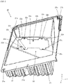
- a head-up display device 1 is, as shown in Fig. 1 , a display device which is installed in a dashboard of a vehicle 2 and irradiates a windshield 2a (a projection member) with a display light L.
- the display light L is reflected by the windshield 2a toward an operator M and is visually recognized by the operator M as a virtual image V.
- the head-up display device 1 includes a housing 10, a heat sink 20, a display unit 30 and a reflector 40.
- the front side plate portion 12 is a portion which forms the +X surface of the housing 10.
- An inclined portion 12a is formed in the -Z portion of the front side plate portion 12.
- the width in the Z direction of the front side plate portion 12 is smaller than the width in the Z direction of the rectangular cylinder portion 11.
- the partition wall portion 13 is a plate that partitions the interior of the rectangular cylinder portion 11 and is formed parallel to the YZ plane.
- the rectangular partition wall opening portion 16 is formed substantially at the center of the partition wall portion 13.
- a light-transmissive cover 14a is fitted into the upper side opening portion 14 so as to close the upper side opening portion 14.
- the light-transmissive cover 14a is made with a light-transmissive synthetic resin material (for example, acrylic resin) and is formed in a curved shape (curved surface shape), and transmits the display light L reflected by the reflector 40 towards the windshield 2a.
- the rear side opening portion 15 is a portion opened on the -X side of the housing 10.
- the heat sink 20 is attached to the rear side opening portion 15, and the -X side of the housing 10 is closed.
- the housing attachment portion 21 is a portion to which the housing 10 is attached, and it has a positioning hole 21a and a through hole 21b.
- a positioning pin (not shown) of the housing 10 is inserted into the positioning hole 21a to precisely position the housing 10 with respect to the heat sink 20.
- the through hole 21b is a through hole for inserting a screw (not shown) for attaching the housing 10.
- the display unit attachment portion 22 is a portion to which the display unit 30 is attached, and it has a wiring substrate attachment portion 22a, a lens unit positioning hole 22b, a first case body fixing portion 22c, a first case body positioning hole 22d and a screw hole 22e.
- the fin portion 23 is a portion formed on the back surface of the display unit attachment portion 22 and absorbing the heat released from the display unit 30 and discharging the heat to the outside, and a large number of protrusions are formed in the fin portion 23 in order to increase the surface area.
- the display unit 30 is a device which emits the display light L, and has, as shown in Fig. 2 , a wiring substrate 31, a light source 32, a connector 33 (see Fig. 4 ), a heat conduction sheet 34, a first case body 35, a lens unit 36, a second case body 37, a diffusion member 38 and a transmissive display element 39.
- the wiring substrate 31 is, for example, a rectangular flat plate formed of a thermally conductive insulating material provided with a predetermined wiring pattern, and as shown in Fig. 4 , a plurality of light sources 32 and the connector 33 are mounted on the wiring pattern (+X side surface) .
- a first positioning hole 31a and a second positioning hole 31b are formed in the wiring substrate 31.
- the first positioning hole 31a is a round hole and is formed in the center portion in the -Z direction of the wiring substrate 31.
- the second positioning hole 31b is a hole which is elongated in the center direction of the first positioning hole 31a, and is formed at the corner in the -Y direction of the +Z direction of the wiring substrate 31.
- the light sources 32 are light emitting bodies such as an LED (Light Emitting Diode), have a light emitting surface in a rectangular shape in planar view having a certain effective area, for example, and are arranged on the wiring substrate 31 (+X surface) in a matrix having intervals different between rows and columns. Specifically, as shown in Fig. 4 , the light sources 32 are arranged in two rows in the row direction (Z direction: a first direction) and are arranged in six columns in the column direction (Y direction: a second direction) perpendicular to the row direction, and the row interval (row pitch) A is larger than the column interval (column pitch) B.
- LED Light Emitting Diode
- the connector 33 is a component for electrically connecting the light sources 32 and a circuit board on which a CPU (Central Processing Unit) or the like which is not shown in the drawing is mounted, and is connected to an FPC (Flexible Printed Circuit) or the like not shown in the drawing.
- a CPU Central Processing Unit
- FPC Flexible Printed Circuit
- the heat conduction sheet 34 shown in Fig. 2 is a sheet component which is made by combining a resin such as silicone and a ceramic filler or a metal filler and is excellent in heat conductivity and adhesion, and is formed in a shape substantially the same as the wiring substrate 31.
- the heat conduction sheet 34 is sandwiched by the wiring substrate 31 and the heat sink 20, and is adhered to the -X surface (see Fig. 4 ) of the wiring substrate 31 and the +X surface (see Fig. 3 ) of the wiring substrate attachment portion 22a of the heat sink 20.
- the fixing portion 35a is a plate portion extending outward from the -X direction end of the first case body 35, and is attached to the first case body fixing portion 22c (see Fig. 3 ) of the heat sink 20.
- a through hole (not shown) is formed in the center of the fixing portion 35a, and by screwing a screw (not shown) inserted into the through hole into the screw hole 22e (see Fig. 3 ) of the heat sink 20, the first case body 35 is fixed to the heat sink 20.
- the positioning pin (not shown) formed in the first case body 35 is inserted into the first case body positioning hole 22d (see Fig. 3 ) of the heat sink 20, and the first case body 35 is precisely positioned with respect to the heat sink 20.
- the stepped surface 35b is a surface formed by a step of the inner peripheral wall of the first case body 35, and is formed at a position contacting the +X surface of the lens unit 36 when the first case body 35 is fixed to the heat sink 20.
- the stepped surface 35b may not only be formed by processing a rectangular cylinder member but may also be formed by connecting two rectangular cylinder members having different widths of the inner peripheral surfaces.
- the lens unit 36 is an optical element formed in a rectangular plate shape by a transparent optical resin or an optical glass, and includes, as shown in Fig. 5 , a flat plate portion 36a, convex lens portions 36b, a reinforcing plate 36c, a first positioning pin 36d, a combined used protrusion 36e, and a first leg portion 36f.
- the flat plate portion 36a is a rectangular flat plate, and a lens array in which the convex lens portions 36b are arrayed in a matrix shape with intervals different between rows and columns is formed in the center of the flat plate portion 36a.
- the first positioning pin 36d and the combined used protrusion 36e and the first leg portion 36f are formed, and the reinforcing plate 36c extends in the -X direction from the outer periphery of the flat plate portion 36a.
- the convex lens portions 36b are convex lenses bulging from both surfaces of the flat plate portion 36a as shown in Fig. 2 , and are formed in a matrix array having intervals different between rows and columns so as to oppose each of the light sources 32.
- the convex lens portions 36b are arranged in two rows in the row direction (Z direction: the first direction) and are arranged in six columns in the column direction (Y direction: the second direction) perpendicular to the row direction, and the row interval A is larger than the column interval B.
- the convex lens portions 36b are formed with the same row interval A and the same column interval B as the light sources 32 and oppose the light sources 32 respectively.
- each light source 32 and each convex lens portion 36b are superimposed in the X direction. Therefore, the radiant light radiated from each of the light sources 32 is irradiated to the opposing convex lens portion 36b and is efficiently collected (substantially collimated).
- connection portions a and b (connection portion a between rows and connection portion b between columns) are formed between the adjacent convex lens portions 36b on the upper surface (+X surface) of the lens unit 36.
- the connection portions a and b are portions that smoothly connect the surfaces of the adjacent convex lens portions 36b with curved lines, and the connection portion a extends in the column direction (Y direction: the second direction) and the connection portion b extends in the row direction (Z direction: the first direction).
- the combined used protrusion 36e is a protrusion formed at the -Y corner of the +Z portion of the -X side surface (the surface opposing the light sources 32) of the flat plate portion 36a, and includes a second leg portion 36h shaped in elliptical frustum protruding from the flat plate portion 36a and a substantially conical second positioning pin 36i protruding from the second leg portion 36h.
- the second leg portion 36h is in contact with the +X surface of the wiring substrate 31, and the second positioning pin 36i is inserted into the second positioning hole 31b (see Fig. 4 ) of the wiring substrate 31, the through hole (not shown) of the heat conduction sheet 34, and the lens unit positioning hole 22b (see Fig. 3 ) of the heat sink 20.
- the second positioning hole 31b of the wiring substrate 31 is formed as an elongated hole, and thus the lens unit 36 can be assembled to the wiring substrate 31 even if a working error occurs in the wiring substrate 31 and the lens unit 36.
- the inner wall of the second positioning hole 31b does not press against the second positioning pin 36i. Therefore, the wiring substrate 31 can be prevented from bending.
- the first leg portion 36f is a protrusion shaped in frustum, and is formed at three corners, except the -Y corner of the +Z portion where the combined used protrusion 36e is formed, of the four corners of the -X side surface (the surface opposing the light sources 32) of the flat plate portion 36a. As shown in Fig. 2 , an end surface of the first leg portion 36f is in contact with the +X surface of the wiring substrate 31.
- the first positioning pin 36d is inserted into the first positioning hole 31a of the wiring substrate 31, and the second positioning pin 36i is inserted into the second positioning hole 31b of the wiring substrate 31.
- the positional relations of the wiring substrate 31 and the lens unit 36 in the Y and Z directions are regulated.
- each light source 32 and each convex lens portion 36b can be superimposed in the X direction.
- the positional relations of the heat sink 20 and the lens unit 36 in the Y and Z directions are regulated.
- the positioning pin (not shown) of the first case body 35 into the first case body positioning hole 22d (see Fig. 3 ) of the heat sink 20 the positional relations of the heat sink 20 and the first case body 35 in the Y and Z directions are regulated.
- the positional relations of the first case body 35 and the lens unit 36 in the Y and Z direction are regulated.
- the transmissive display element 39 is a device that displays an image by transmitted light, and is, for example, a light transmissive liquid crystal display panel in which polarizing films are provided on both surfaces of a liquid crystal cell in which liquid crystal is sealed in a pair of light-transmissive substrates.
- the transmissive display element 39 displays speed and engine speed based on output signals from a vehicle speed sensor and an engine rotation sensor.
- An image displayed by the transmissive display element 39 is transmissively illuminated by the emitted light emitted from the diffusion member 38 and irradiated to the reflector 40.
- Information displayed by the transmissive display element 39 is not limited to the vehicle speed and the engine speed and may be any information, for example, travelling distance information, navigation information, and outside air temperature information.
- the concave mirror 41 is a mirror in which a reflection layer is vapor-deposited and formed on a resin substrate made with polycarbonate having a concave surface.
- the concave mirror 41 enlarges the display light L irradiated from the transmissive display element 39 and reflects it toward the light-transmissive cover 14a fitted into the upper side opening portion 14 of the housing 10. Therefore, the mirror holder 42 holding the concave mirror 41 is disposed to be inclined in the -Z portion in the +X direction inside the housing 10.
- the display light L reflected by the concave mirror 41 passes through the light-transmissive cover 14a and is irradiated on the windshield 2a.
- the luminance of the emitted light irradiated from the light sources 32 arranged in a rectangular lattice shape to each convex lens portion 36b and emitted from the lens unit 36 can be equalized. Therefore, the path of light beams passing through the lens unit 36 of the head-up display device 1 according to an embodiment of the invention will be described in comparison with the path of light beams passing through a lens unit 56 of a conventional head-up display device.
- the radiant light L1 radiated from the adjacent light sources 32 is superimposed and emitted from valleys 56j and 56k of the adjacent lens portions 56b. Therefore, as shown in Fig. 9 (b) and Fig. 10 (b) , the luminance of the emitted light L2 becomes high at the valleys 56j and 56k. Particularly, the luminance at the valley 56k of a column shown in Fig. 10 (b) is higher than the luminance at the center of the lens portion 56b and the luminance unevenness is remarkable because the interval B (see Fig. 6 ) of the light sources 32 is narrow and the amount of light irradiated from the adjacent light sources 32 is large.
- a width Wa in the short direction of the connection portion a is smaller than the width Wb in the short direction of the connection portion b
- the curvature radius Ra of the connection portion a is smaller than the curvature radius Rb of the connection portion b. Therefore, a width Pa (see Fig. 11 (a) ) of the emitted light L2 emitted from the connection portion a is equal to or larger than a width Pb (see Fig. 12 (a) ) of the emitted light L2 emitted from the connection portion b.
- the luminance of the emitted light L2 emitted from the lens unit 36 is equalized and it becomes possible to suppress unevenness.
- the convex lens portions 36b bulge from both surfaces of the flat plate portion 36a of the lens unit 36 has been shown.
- the invention is not limited thereto.
- the surface (-X surface) opposing the light sources 32 may be a flat surface.
- connection portions a and b are formed at the boundaries of the convex lens portions 36b on the +X surface of the lens unit 36 .
- the invention is not limited thereto.
- the connection portions a and b may be formed not only on the +X surface of the lens unit 36 but also at the boundaries of the convex lens portions 36b on the -X surface.
- the interval A of the light sources 32 and the convex lens portions 36b in the row direction (Z direction: the first direction) is larger than the interval B in the column direction (Y direction: the second direction) .
- the curvature radius Ra of the connection portion a extending in the column direction (Y direction: the second direction) is smaller than the curvature radius Rb of the connection portion b extending in the row direction (Z direction: the first direction).
- the invention is not limited thereto.
- the interval A of the light sources 32 and the convex lens portions 36b in the row direction may be smaller than the interval B in the column direction, and at the boundaries of the convex lens portions 36b, the curvature radius Ra of the connection portion a extending in the column direction may be larger than the curvature radius Rb of the connection portion b extending in the row direction.
- connection portions a and b are curved grooves.
- the invention is not limited thereto.
- the cross-sectional shapes of the connection portions a and b may be made flat.
- the width Wa of the short direction of the connection portion a extending in the column direction is smaller than the width Wb of the short direction of the connection portion b extending in the row direction when the interval A of the light sources 32 and the convex lens portions 36b in the row direction is larger than the interval B in the column direction, and Wa is larger than Wb when A is smaller than B.
- the display unit 30 only has the lens unit 36 as a lens collecting the display light L has been shown.
- the invention is not limited thereto.
- a lens such as a cylindrical lens may be disposed between the lens unit 36 and the diffusion member 38 to further equalize the luminance of the radiant light irradiated to the transmissive display element 39.
- the head-up display device 1 is installed in the vehicle 2 in the above description.
- the invention is not limited thereto.
- the head-up display device 1 can also be installed in other conveyances such as watercraft and aircraft.
- the head-up display device is not limited to those installed in a conveyance, and it can also be applied to tabletop interiors and the like installed indoors.
- the invention is suitable for a head-up display device mounted on a vehicle.
- a head-up display device wherein the head-up display device comprises a plurality of light sources arrayed in matrix in a first direction and a second direction orthogonal to the first direction on a substrate, and a lens unit in which convex lens portions which collect radiant light radiated from the light sources are formed opposing each light source, the plurality of light sources are arranged at a first arrangement interval in the first direction and are arranged at a second arrangement interval, which is smaller than the first arrangement interval, in the second direction, the lens unit includes a first connection portion and a second connection portion formed at boundaries of the adjacent convex lens portions, the first connection portion extends in the first direction, the second connection portion extends in the second direction, and a width of a short direction of the first connection portion is larger than a width of a short direction of the second connection portion.
- the substrate has a round hole used for positioning, and an elongated hole used for positioning formed elongated towards the round hole
- the lens unit has a first positioning pin fitted into the round hole and a second positioning pin fitted into the elongated hole, and a gap is formed between the elongated hole and the second positioning pin fitted into the elongated hole.
- a lens unit which collects and outputs light from light sources arrayed in matrix wherein the lens unit includes a lens array in which convex lens portions, which are formed opposing each light source and collect radiant light radiated from the opposed light sources, are formed in matrix, the convex lens portions are arranged at a first arrangement interval in a first direction and are arranged at a second arrangement interval, which is smaller than the first arrangement interval, in a second direction, the lens array includes a first connection portion and a second connection portion formed at boundaries of the adjacent convex lens portions, the first connection portion extends in the first direction, the second connection portion extends in the second direction, and a width of a short direction of the first connection portion is larger than a width of a short direction of the second connection portion.
Abstract
Description
- The present invention relates to a head-up display device and a lens unit.
- As a head-up display device for displaying information on a windshield of a vehicle and the like, a head-up display device disclosed in Patent Literature 1 is known. The head-up display device includes a plurality of light sources mounted on a wiring substrate and a lens unit having a plurality of convex lens portions formed to face each light source. According to the head-up display device, radiant light radiated from each light source is collected by each convex lens portion opposing the light source, and thus the radiant light can be efficiently collected.
- However, there is a problem in the head-up display device described in the Patent Literature 1 that a sharp valley is formed between adjacent convex lens portions and the radiant light from adjacent light sources is superimposed in the valley and emitted, and thus unevenness occurs in the luminance of the emitted light emitted from the lens unit.
- As a display device for solving this problem, a display device disclosed in
Patent Literature 2 is known. In the lens unit of the head-up display device, superimposition of the emitted light is suppressed and occurrence of unevenness in luminance is suppressed by providing a connection portion at the boundary between the adjacent convex lens portions. -
- PTL 1:
JP-A-2013-164512 - PTL 2:
JP-A-2009-122654 - The head-up display device disclosed in the
Patent Literature 2 is based on the premise that the light sources are arranged at the same interval in the row direction and in the column direction. However, there are cases where it is necessary to make the interval in the row direction different from the interval in the column direction of the light sources due to the structure of the device, the characteristics of the light sources, etc. In the display device described in thePatent Literature 2, there is a problem that, when the intervals of the light sources and the convex lens portions arrayed in matrix are made different between rows and columns, the emitted light emitted from the connection portions in rows or columns is superimposed and unevenness occurs in luminance. - The invention has been made in view of the above circumstances, and an object of the invention is to provide a head-up display device and a lens unit, in which luminance unevenness of emitted light emitted from the lens unit is small even when intervals of light sources arrayed in matrix are different between rows and columns.
- In order to achieve the above object, the head-up display device of the invention comprises
a plurality of light sources arrayed in matrix in a first direction and a second direction orthogonal to the first direction on a substrate, and
a lens unit in which convex lens portions which collect radiant light radiated from the light sources are formed opposing each light source,
the plurality of light sources are arranged at a first arrangement interval in the first direction and are arranged at a second arrangement interval, which is smaller than the first arrangement interval, in the second direction,
the lens unit includes a first connection portion and a second connection portion formed at boundaries of the adjacent convex lens portions,
the first connection portion extends in the first direction,
the second connection portion extends in the second direction,
and a width of a short direction of the first connection portion is larger than a width of a short direction of the second connection portion. - In order to achieve the above object, the lens unit of the invention is
a lens unit which collects and outputs light from light sources arrayed in matrix, wherein
the lens unit includes a lens array in which convex lens portions, which are formed opposing each light source and collect radiant light radiated from the opposed light sources, are formed in matrix,
the convex lens portions are arranged at a first arrangement interval in a first direction and are arranged at a second arrangement interval, which is smaller than the first arrangement interval, in a second direction,
the lens array includes a first connection portion and a second connection portion formed at boundaries of the adjacent convex lens portions,
the first connection portion extends in the first direction,
the second connection portion extends in the second direction,
and a width of a short direction of the first connection portion is larger than a width of a short direction of the second connection portion. - According to the invention, it is possible to suppress occurrence of unevenness in luminance of emitted light emitted from the lens unit in a lens unit in which convex lens portions are arranged in matrix with intervals different between rows and columns.
-
-
Fig. 1 is a schematic view of a vehicle on which a head-up display device according to an embodiment of the invention is mounted. -
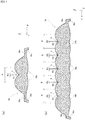
Fig. 2 is a cross-sectional view of a head-up display device according to an embodiment. -
Fig. 3 is a perspective view of a heat sink of the head-up display device according to the embodiment. -
Fig. 4 is a perspective view of a wiring substrate of the head-up display device according to the embodiment. -
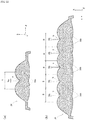
Fig. 5 is a perspective view of a lens unit of the head-up display device according to the embodiment. -
Fig. 6 is a plan view of the lens unit of the head-up display device according to the embodiment. -
Figs. 7 (a) and (b) are respectively a C-C cross-sectional view and a D-D cross-sectional view of the lens unit shown inFig. 6 . -
Figs. 8 (a) and (b) are respectively enlarged cross-sectional views ofFigs. 7 (a) and (b) . -
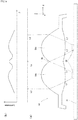
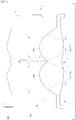
Fig. 9 (a) is a schematic view showing a path of light beams passing through a lens unit of a conventional head-up display device on the XZ plane, and (b) is a graph showing a relation between the luminance of emitted light emitted from the lens unit and the Z axis. -
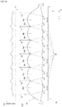
Fig. 10 (a) is a schematic view showing a path of light beams passing through a lens unit of a conventional head-up display device on the XY plane, and (b) is a graph showing a relation between the luminance of emitted light emitted from the lens unit and the Y axis. -
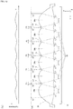
Fig. 11 (a) is a schematic view showing a path of light beams passing through the lens unit of the head-up display device according to the embodiment on the XZ plane, and (b) is a graph showing a relation between the luminance of emitted light emitted from the lens unit of the head-up display device according to the embodiment and the Z axis. -
Fig. 12 (a) is a schematic view showing a path of light beams passing through a lens unit of a head-up display device according to an embodiment on the XY plane, and (b) is a graph showing a relation between the luminance of emitted light emitted from the lens unit of the head-up display device according to the embodiment and the Y axis. -
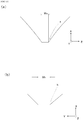
Fig. 13 (a) is a C-C cross-sectional view and (b) is a D-D cross-sectional view of a lens unit according to another embodiment. -
Figs. 14 (a) and (b) are respectively enlarged cross-sectional views ofFigs. 13 (a) and (b) . - An embodiment of the head-up display device according to the invention will be described with reference to the drawings. For a better understanding of the configuration of the head-up display device, description will be made using XYZ coordinates in which the travelling direction of the vehicle is the X direction, the width direction of the vehicle is the Y direction, and the vertical direction is the Z direction. In addition, the directions pointed by arrows of X, Y, Z coordinates are defined as + (plus), and the opposite directions are defined as - (minus).
- A head-up display device 1 according to the present embodiment is, as shown in
Fig. 1 , a display device which is installed in a dashboard of avehicle 2 and irradiates awindshield 2a (a projection member) with a display light L. The display light L is reflected by thewindshield 2a toward an operator M and is visually recognized by the operator M as a virtual image V. - As shown in
Fig. 2 , the head-up display device 1 includes ahousing 10, aheat sink 20, adisplay unit 30 and areflector 40. - The
housing 10 is a non-light-transmissive case in a rectangular cylinder shape and is formed with a non-light-transmissive resin material or a metal material. Arectangular cylinder portion 11, a frontside plate portion 12, apartition wall portion 13, an upperside opening portion 14, a rearside opening portion 15 and a partition wall opening portion 16 are formed in thehousing 10. - The
rectangular cylinder portion 11 is a portion in a rectangular cylinder shape. The upperside opening portion 14 is obliquely formed in the +Z portion in the +X direction of therectangular cylinder portion 11. - The front
side plate portion 12 is a portion which forms the +X surface of thehousing 10. Aninclined portion 12a is formed in the -Z portion of the frontside plate portion 12. In addition, since the upperside opening portion 14 is obliquely formed in the +Z portion of the frontside plate portion 12, the width in the Z direction of the frontside plate portion 12 is smaller than the width in the Z direction of therectangular cylinder portion 11. - The
partition wall portion 13 is a plate that partitions the interior of therectangular cylinder portion 11 and is formed parallel to the YZ plane. The rectangular partition wall opening portion 16 is formed substantially at the center of thepartition wall portion 13. - A light-
transmissive cover 14a is fitted into the upperside opening portion 14 so as to close the upperside opening portion 14. The light-transmissive cover 14a is made with a light-transmissive synthetic resin material (for example, acrylic resin) and is formed in a curved shape (curved surface shape), and transmits the display light L reflected by thereflector 40 towards thewindshield 2a. - The rear
side opening portion 15 is a portion opened on the -X side of thehousing 10. Theheat sink 20 is attached to the rearside opening portion 15, and the -X side of thehousing 10 is closed. - The
heat sink 20 is a heat radiating component for absorbing the heat released from thedisplay unit 30 and discharging the heat to the outside, and is formed by aluminum and the like. As shown inFig. 3 , ahousing attachment portion 21, a displayunit attachment potion 22 and afin portion 23 are formed in theheat sink 20. - The
housing attachment portion 21 is a portion to which thehousing 10 is attached, and it has apositioning hole 21a and a throughhole 21b. A positioning pin (not shown) of thehousing 10 is inserted into thepositioning hole 21a to precisely position thehousing 10 with respect to theheat sink 20. The throughhole 21b is a through hole for inserting a screw (not shown) for attaching thehousing 10. - The display
unit attachment portion 22 is a portion to which thedisplay unit 30 is attached, and it has a wiringsubstrate attachment portion 22a, a lensunit positioning hole 22b, a first casebody fixing portion 22c, a first casebody positioning hole 22d and ascrew hole 22e. - The
fin portion 23 is a portion formed on the back surface of the displayunit attachment portion 22 and absorbing the heat released from thedisplay unit 30 and discharging the heat to the outside, and a large number of protrusions are formed in thefin portion 23 in order to increase the surface area. - The
display unit 30 is a device which emits the display light L, and has, as shown inFig. 2 , awiring substrate 31, alight source 32, a connector 33 (seeFig. 4 ), aheat conduction sheet 34, afirst case body 35, alens unit 36, asecond case body 37, adiffusion member 38 and atransmissive display element 39. - The
wiring substrate 31 is, for example, a rectangular flat plate formed of a thermally conductive insulating material provided with a predetermined wiring pattern, and as shown inFig. 4 , a plurality oflight sources 32 and theconnector 33 are mounted on the wiring pattern (+X side surface) . In addition, afirst positioning hole 31a and asecond positioning hole 31b are formed in thewiring substrate 31. Thefirst positioning hole 31a is a round hole and is formed in the center portion in the -Z direction of thewiring substrate 31. Thesecond positioning hole 31b is a hole which is elongated in the center direction of thefirst positioning hole 31a, and is formed at the corner in the -Y direction of the +Z direction of thewiring substrate 31. - The
light sources 32 are light emitting bodies such as an LED (Light Emitting Diode), have a light emitting surface in a rectangular shape in planar view having a certain effective area, for example, and are arranged on the wiring substrate 31 (+X surface) in a matrix having intervals different between rows and columns. Specifically, as shown inFig. 4 , thelight sources 32 are arranged in two rows in the row direction (Z direction: a first direction) and are arranged in six columns in the column direction (Y direction: a second direction) perpendicular to the row direction, and the row interval (row pitch) A is larger than the column interval (column pitch) B. - The
connector 33 is a component for electrically connecting thelight sources 32 and a circuit board on which a CPU (Central Processing Unit) or the like which is not shown in the drawing is mounted, and is connected to an FPC (Flexible Printed Circuit) or the like not shown in the drawing. - The
heat conduction sheet 34 shown inFig. 2 is a sheet component which is made by combining a resin such as silicone and a ceramic filler or a metal filler and is excellent in heat conductivity and adhesion, and is formed in a shape substantially the same as thewiring substrate 31. Theheat conduction sheet 34 is sandwiched by thewiring substrate 31 and theheat sink 20, and is adhered to the -X surface (seeFig. 4 ) of thewiring substrate 31 and the +X surface (seeFig. 3 ) of the wiringsubstrate attachment portion 22a of theheat sink 20. - The
first case body 35 is a component in a rectangular cylinder shape formed with a non-light-transmissive resin material or the like, and is sandwiched by theheat sink 20 and thepartition wall portion 13. A fixingportion 35a, a steppedsurface 35b, and a positioning pin (not shown) are formed in thefirst case body 35. - The fixing
portion 35a is a plate portion extending outward from the -X direction end of thefirst case body 35, and is attached to the first casebody fixing portion 22c (seeFig. 3 ) of theheat sink 20. A through hole (not shown) is formed in the center of the fixingportion 35a, and by screwing a screw (not shown) inserted into the through hole into thescrew hole 22e (seeFig. 3 ) of theheat sink 20, thefirst case body 35 is fixed to theheat sink 20. In this case, the positioning pin (not shown) formed in thefirst case body 35 is inserted into the first casebody positioning hole 22d (seeFig. 3 ) of theheat sink 20, and thefirst case body 35 is precisely positioned with respect to theheat sink 20. - The stepped
surface 35b is a surface formed by a step of the inner peripheral wall of thefirst case body 35, and is formed at a position contacting the +X surface of thelens unit 36 when thefirst case body 35 is fixed to theheat sink 20. The steppedsurface 35b may not only be formed by processing a rectangular cylinder member but may also be formed by connecting two rectangular cylinder members having different widths of the inner peripheral surfaces. - The
lens unit 36 is an optical element formed in a rectangular plate shape by a transparent optical resin or an optical glass, and includes, as shown inFig. 5 , aflat plate portion 36a,convex lens portions 36b, a reinforcingplate 36c, afirst positioning pin 36d, a combined usedprotrusion 36e, and afirst leg portion 36f. - The
flat plate portion 36a is a rectangular flat plate, and a lens array in which theconvex lens portions 36b are arrayed in a matrix shape with intervals different between rows and columns is formed in the center of theflat plate portion 36a. In addition, in the -X side surface (the surface opposing the light sources 32) of theflat plate portion 36a, thefirst positioning pin 36d and the combined usedprotrusion 36e and thefirst leg portion 36f are formed, and the reinforcingplate 36c extends in the -X direction from the outer periphery of theflat plate portion 36a. - The
convex lens portions 36b are convex lenses bulging from both surfaces of theflat plate portion 36a as shown inFig. 2 , and are formed in a matrix array having intervals different between rows and columns so as to oppose each of thelight sources 32. Specifically, as shown inFig. 6 , theconvex lens portions 36b are arranged in two rows in the row direction (Z direction: the first direction) and are arranged in six columns in the column direction (Y direction: the second direction) perpendicular to the row direction, and the row interval A is larger than the column interval B. In other words, theconvex lens portions 36b are formed with the same row interval A and the same column interval B as thelight sources 32 and oppose thelight sources 32 respectively. As a result, eachlight source 32 and eachconvex lens portion 36b are superimposed in the X direction. Therefore, the radiant light radiated from each of thelight sources 32 is irradiated to the opposingconvex lens portion 36b and is efficiently collected (substantially collimated). - Moreover, connection portions a and b (connection portion a between rows and connection portion b between columns) are formed between the adjacent
convex lens portions 36b on the upper surface (+X surface) of thelens unit 36. The connection portions a and b are portions that smoothly connect the surfaces of the adjacentconvex lens portions 36b with curved lines, and the connection portion a extends in the column direction (Y direction: the second direction) and the connection portion b extends in the row direction (Z direction: the first direction). - The cross-sectional shapes of the connection portions a and b are curved grooves as shown being enlarged in
Figs. 7 (a) and (b) and further inFigs. 8 (a) and (b) . As shown inFigs. 8 (a) and (b) , the connection portions a and b are formed such that a width Wa in a short direction of the connection portion a is smaller than a width Wb in a short direction of the connection portion b, and a curvature radius Ra of the connection portion a is smaller than a curvature radius Rb of the connection portion b. - As shown in
Fig. 5 , the reinforcingplate 36c is a plate extending in the -X direction from the outer periphery of theflat plate portion 36a, and it prevents thelens unit 36 from bending. In addition, a notchedportion 36g for avoiding interference with theconnector 33 mounted on thewiring substrate 31 is formed at the center of the +Z portion of the reinforcingplate 36c. - The
first positioning pin 36d is a substantially conical protrusion formed at the center of the -Z portion of the -X side surface (the surface opposing the light sources 32) of theflat plate portion 36a, and is inserted into thefirst positioning hole 31a (seeFig. 4 ) of thewiring substrate 31, the through hole (not shown) of theheat conduction sheet 34, and the lensunit positioning hole 22b (seeFig. 3 ) of theheat sink 20. - The combined used
protrusion 36e is a protrusion formed at the -Y corner of the +Z portion of the -X side surface (the surface opposing the light sources 32) of theflat plate portion 36a, and includes asecond leg portion 36h shaped in elliptical frustum protruding from theflat plate portion 36a and a substantially conicalsecond positioning pin 36i protruding from thesecond leg portion 36h. Thesecond leg portion 36h is in contact with the +X surface of thewiring substrate 31, and thesecond positioning pin 36i is inserted into thesecond positioning hole 31b (seeFig. 4 ) of thewiring substrate 31, the through hole (not shown) of theheat conduction sheet 34, and the lensunit positioning hole 22b (seeFig. 3 ) of theheat sink 20. Thesecond positioning hole 31b of thewiring substrate 31 is formed as an elongated hole, and thus thelens unit 36 can be assembled to thewiring substrate 31 even if a working error occurs in thewiring substrate 31 and thelens unit 36. In addition, even if thewiring substrate 31 expands due to the heat emitted from thelight sources 32, the inner wall of thesecond positioning hole 31b does not press against thesecond positioning pin 36i. Therefore, thewiring substrate 31 can be prevented from bending. - The
first leg portion 36f is a protrusion shaped in frustum, and is formed at three corners, except the -Y corner of the +Z portion where the combined usedprotrusion 36e is formed, of the four corners of the -X side surface (the surface opposing the light sources 32) of theflat plate portion 36a. As shown inFig. 2 , an end surface of thefirst leg portion 36f is in contact with the +X surface of thewiring substrate 31. - The
first positioning pin 36d is inserted into thefirst positioning hole 31a of thewiring substrate 31, and thesecond positioning pin 36i is inserted into thesecond positioning hole 31b of thewiring substrate 31. In this way, the positional relations of thewiring substrate 31 and thelens unit 36 in the Y and Z directions are regulated. As a result, eachlight source 32 and eachconvex lens portion 36b can be superimposed in the X direction. - By bringing the end surfaces of the
first leg portion 36f and thesecond leg portion 36h into contact with the +X surface of thewiring substrate 31, a distance between thelight sources 32 and theconvex lens portions 36b can be regulated to a predetermined value (5 mm or less) . By fixing thefirst case body 35 to theheat sink 20, the steppedsurface 35b of thefirst case body 35 comes into contact with the +X surface of thelens unit 36 and presses against thelens unit 36. In this way, the end surfaces of thefirst leg portion 36f and thesecond leg portion 36h of thelens unit 36 are in contact with the +X surface of thewiring substrate 31. - Further, by inserting the
first positioning pin 36d and thesecond positioning pin 36i of thelens unit 36 into the lensunit positioning hole 22b (seeFig. 3 ) of theheat sink 20 respectively, the positional relations of theheat sink 20 and thelens unit 36 in the Y and Z directions are regulated. By inserting the positioning pin (not shown) of thefirst case body 35 into the first casebody positioning hole 22d (seeFig. 3 ) of theheat sink 20, the positional relations of theheat sink 20 and thefirst case body 35 in the Y and Z directions are regulated. As a result, the positional relations of thefirst case body 35 and thelens unit 36 in the Y and Z direction are regulated. - The
second case body 37 shown inFig. 2 is a frame-shaped member in which arectangular opening portion 37a is formed at the center, and thesecond case body 37 is formed with a non-light-transmissive resin material. Thesecond case body 37 is fixed to the +X surface of thepartition wall portion 13 such that therectangular opening portion 37a and the partition wall opening portion 16 are superimposed. In addition, thediffusion member 38 and thetransmissive display element 39 are fitted in therectangular opening portion 37a and held. - The
diffusion member 38 is a flat plate formed with a light transmissive synthetic resin having milky white color for example, and is disposed along thetransmissive display element 39. Thediffusion member 38 diffuses the emitted light emitted from thelens unit 36 and irradiates thetransmissive display element 39. - The
transmissive display element 39 is a device that displays an image by transmitted light, and is, for example, a light transmissive liquid crystal display panel in which polarizing films are provided on both surfaces of a liquid crystal cell in which liquid crystal is sealed in a pair of light-transmissive substrates. Thetransmissive display element 39 displays speed and engine speed based on output signals from a vehicle speed sensor and an engine rotation sensor. An image displayed by thetransmissive display element 39 is transmissively illuminated by the emitted light emitted from thediffusion member 38 and irradiated to thereflector 40. Information displayed by thetransmissive display element 39 is not limited to the vehicle speed and the engine speed and may be any information, for example, travelling distance information, navigation information, and outside air temperature information. - The
reflector 40 is a device that reflects the display light L irradiated from thetransmissive display element 39 and irradiates it to thewindshield 2a, and has, as shown inFig. 2 , aconcave mirror 41 and amirror holder 42. - The
concave mirror 41 is a mirror in which a reflection layer is vapor-deposited and formed on a resin substrate made with polycarbonate having a concave surface. Theconcave mirror 41 enlarges the display light L irradiated from thetransmissive display element 39 and reflects it toward the light-transmissive cover 14a fitted into the upperside opening portion 14 of thehousing 10. Therefore, themirror holder 42 holding theconcave mirror 41 is disposed to be inclined in the -Z portion in the +X direction inside thehousing 10. The display light L reflected by theconcave mirror 41 passes through the light-transmissive cover 14a and is irradiated on thewindshield 2a. - According to the head-up display device 1 having the above configuration, the luminance of the emitted light irradiated from the
light sources 32 arranged in a rectangular lattice shape to eachconvex lens portion 36b and emitted from thelens unit 36 can be equalized. Therefore, the path of light beams passing through thelens unit 36 of the head-up display device 1 according to an embodiment of the invention will be described in comparison with the path of light beams passing through alens unit 56 of a conventional head-up display device. - As shown in
Fig. 9 to Fig. 12 , radiant light L1 radiated from thelight sources 32 spreads to a predetermined width from a light emitting surface and is irradiated to thelens units lens units lens portions light source 32 and is emitted from thelens units - In this case, as shown in
Fig. 9 (a) andFig. 10 (a) , in thelens unit 56 of the conventional head-up display device, the radiant light L1 radiated from the adjacentlight sources 32 is superimposed and emitted fromvalleys adjacent lens portions 56b. Therefore, as shown inFig. 9 (b) andFig. 10 (b) , the luminance of the emitted light L2 becomes high at thevalleys valley 56k of a column shown inFig. 10 (b) is higher than the luminance at the center of thelens portion 56b and the luminance unevenness is remarkable because the interval B (seeFig. 6 ) of thelight sources 32 is narrow and the amount of light irradiated from the adjacentlight sources 32 is large. - In the
lens unit 36 of the head-up display device 1 according to the embodiment of the invention, the connection portions a and b (seeFigs. 6 and7 ) are formed betweenadjacent lens portions 36b. For this reason, the radiant light L1 radiated from the adjacentlight sources 32 and entering the connection portions a and b is largely refracted due to the shapes of the connection portions a and b. Therefore, the emitted light L2 radiated from the connection portions a and b is largely refracted obliquely with respect to the X direction, does not reach thediffusion member 38 and does not contribute to illumination of thetransmissive display element 39. As a result, the luminance of the emitted light L2 emitted from thelens unit 36 is equalized and unevenness is suppressed. - In addition, as shown in
Figs. 7 (a) and (b) andFigs. 8 (a) and (b) , the width Wa in the short direction of the connection portion a is smaller than the width Wb in the short direction of the connection portion b, and the curvature radius Ra of the connection portion a is smaller than the curvature radius Rb of the connection portion b. Therefore, a width Pa (seeFig. 11 (a) ) of the emitted light L2 emitted from the connection portion a is equal to or larger than a width Pb (seeFig. 12 (a) ) of the emitted light L2 emitted from the connection portion b. As a result, an effect of suppressing the luminance at the connection portion b larger than that at the connection portion a can be obtained, and thus the luminance of the emitted light L2 emitted from thelens unit 36 can be equalized and it becomes possible to suppress unevenness. - According to the embodiment described above, the following effects are obtained.
- (1) The head-up display device 1 according to the embodiment includes the plurality of
light sources 32 arrayed in matrix along the Y direction and the Z direction on thewiring substrate 31, and thelens unit 36 in which theconvex lens portions 36b which collect the radiant light L1 radiated from thelight sources 32 are formed opposing eachlight source 32. The plurality oflight sources 32 are arranged at the interval A in the Z direction (the first direction: row direction) and arranged at the interval B, which is smaller than the interval A, in the Y direction (the second direction: column direction) . Further, thelens unit 36 has the connection portions a and b formed at boundaries of the adjacentconvex lens portions 36b. The connection portion a extends in the Y direction (the second direction: column direction), and the connection portion b extends in the Z direction (the first direction: row direction). The width Wa of the short direction of the connection portion a is smaller than the width Wb of the short direction of the connection portion b.
According to this configuration, the luminance of the emitted light L2 emitted from thelens unit 36 is equalized and unevenness can be suppressed. - (2) The connection portions a and b are formed by curved grooves. According to this configuration, it is possible not only to equalize the luminance of the emitted light L2 emitted from the
lens unit 36 but also to increase the strength of thelens unit 36. - (3) The curvature radius Ra of the curved groove of the connection portion a is smaller than the curvature radius Rb of the connection portion b. Therefore, the emitted light L1 radiated to the connection portion b more than that to the connection portion a can be refracted more greatly and emitted, and the luminance of the emitted light L2 emitted from the
lens unit 36 can be equalized. - (4) The
wiring substrate 31 has thefirst positioning hole 31a which is a round hole, and thesecond positioning hole 31b which is an elongated hole formed elongated toward thefirst positioning hole 31a. Thelens unit 36 has thefirst positioning pin 36d fitted into afirst positioning hole 31a and thesecond positioning pin 36i fitted into thesecond positioning hole 31b, and a gap is formed between thesecond positioning hole 31b and thesecond positioning pin 36i fitted into thesecond positioning hole 31b. According to this configuration, thelens unit 36 can be assembled to thewiring substrate 31 even if a working error occurs in thewiring substrate 31 and thelens unit 36. In addition, even if thewiring substrate 31 expands due to the heat emitted from thelight sources 32, the inner wall of thesecond positioning hole 31b does not press against thesecond positioning pin 36i. Therefore, thewiring substrate 31 can be prevented from bending. - (5) A reinforcing plate which extends from the outer periphery of the lens unit and prevents the lens unit from bending is further provided. According to this configuration, the
lens unit 36 can be prevented from bending by a simple structure. - (6) The notched
portion 36g for avoiding interference with components such as theconnector 33 mounted on thewiring substrate 31 is formed in the reinforcingplate 36c. According to this configuration, components such theconnector 33 mounted on thewiring substrate 31 do not interfere with the reinforcingplate 36c because of the notchedpotion 36g, and thus the distance between thelight sources 32 arranged on thewiring substrate 31 and theconvex lens portions 36b formed in thelens unit 36 can be regulated to a predetermined value. - (7) The
lens unit 36 according to the embodiment collects and outputs the light from thelight sources 32 arrayed in matrix, and includes a lens array in which theconvex lens portions 36b, which are formed opposing each of thelight sources 32 and collect the radiant light radiated from the opposedlight sources 32, are formed in matrix. Theconvex lens portions 36b are arranged at a first arrangement interval (A) in a first direction (Z direction) and are arranged at a second arrangement interval (B), which is smaller than the first arrangement interval (A), in a second direction (Y direction). The lens array includes a first connection portion (b) and a second connection portion (a) formed at boundaries of the adjacentconvex lens portions 36b. The first connection portion (b) extends in the first direction (Z direction), and the second connection portion (a) extends in the second direction (Y direction). A width (Wb) of a short direction of the first connection portion (b) is larger than a width (Wa) of a short direction of the second connection portion (a). - According to this configuration, the luminance of the emitted light L2 emitted from the
lens unit 36 is equalized and it becomes possible to suppress unevenness. - The invention is not limited by the above embodiment and the drawings. Variations (including deletion of constituent elements) can definitely be added to the above embodiment and drawings.
- In the above description, an example in which the
convex lens portions 36b bulge from both surfaces of theflat plate portion 36a of thelens unit 36 has been shown. However, the invention is not limited thereto. For example, the surface (-X surface) opposing thelight sources 32 may be a flat surface. - In the above description, an example in which the connection portions a and b are formed at the boundaries of the
convex lens portions 36b on the +X surface of thelens unit 36 has been shown. However, the invention is not limited thereto. For example, the connection portions a and b may be formed not only on the +X surface of thelens unit 36 but also at the boundaries of theconvex lens portions 36b on the -X surface. - In the above description, the interval A of the
light sources 32 and theconvex lens portions 36b in the row direction (Z direction: the first direction) is larger than the interval B in the column direction (Y direction: the second direction) . At the boundaries of theconvex lens portions 36b, the curvature radius Ra of the connection portion a extending in the column direction (Y direction: the second direction) is smaller than the curvature radius Rb of the connection portion b extending in the row direction (Z direction: the first direction). However, the invention is not limited thereto. For example, the interval A of thelight sources 32 and theconvex lens portions 36b in the row direction may be smaller than the interval B in the column direction, and at the boundaries of theconvex lens portions 36b, the curvature radius Ra of the connection portion a extending in the column direction may be larger than the curvature radius Rb of the connection portion b extending in the row direction. - In the above description, the cross-sectional shapes of the connection portions a and b are curved grooves. However, the invention is not limited thereto. For example, as shown in
Figs. 13 (a) and (b) andFigs. 14 (a) and (b) , the cross-sectional shapes of the connection portions a and b may be made flat. Also in this case, it is formed such that, at the boundaries of theconvex lens portions 36b, the width Wa of the short direction of the connection portion a extending in the column direction is smaller than the width Wb of the short direction of the connection portion b extending in the row direction when the interval A of thelight sources 32 and theconvex lens portions 36b in the row direction is larger than the interval B in the column direction, and Wa is larger than Wb when A is smaller than B. - In the above description, an example in which the
display unit 30 only has thelens unit 36 as a lens collecting the display light L has been shown. However, the invention is not limited thereto. For example, a lens such as a cylindrical lens may be disposed between thelens unit 36 and thediffusion member 38 to further equalize the luminance of the radiant light irradiated to thetransmissive display element 39. - An example in which the head-up display device 1 is installed in the
vehicle 2 has been shown in the above description. However, the invention is not limited thereto. The head-up display device 1 can also be installed in other conveyances such as watercraft and aircraft. Moreover, the head-up display device is not limited to those installed in a conveyance, and it can also be applied to tabletop interiors and the like installed indoors. - In the above description, descriptions of well-known technical matters have been appropriately omitted for a better understanding of the invention.
- The invention is suitable for a head-up display device mounted on a vehicle.
-
- 1: head-up display device
- 31: wiring substrate
- 31a: first positioning hole
- 31b: second positioning hole
- 32: light source
- 36: lens unit
- 36b: convex lens portion
- 36c: reinforcing plate
- 36d: first positioning pin
- 36i: second positioning pin
- 36g: notched portion
- A: interval in row direction
- B: interval in column direction
- a: connection portion extending in column direction
- b: connection portion extending in row direction
- L1: radiant light
- Wa: width of short direction of connection portion a extending in column direction
- Wb: width of short direction of connection portion b extending in row direction
- Ra: curvature radius of curved groove of connection portion a
- Rb: curvature radius of curved groove of connection portion b
- A head-up display device, wherein the head-up display device comprises
a plurality of light sources arrayed in matrix in a first direction and a second direction orthogonal to the first direction on a substrate, and
a lens unit in which convex lens portions which collect radiant light radiated from the light sources are formed opposing each light source,
the plurality of light sources are arranged at a first arrangement interval in the first direction and are arranged at a second arrangement interval, which is smaller than the first arrangement interval, in the second direction,
the lens unit includes a first connection portion and a second connection portion formed at boundaries of the adjacent convex lens portions,
the first connection portion extends in the first direction,
the second connection portion extends in the second direction,
and a width of a short direction of the first connection portion is larger than a width of a short direction of the second connection portion. - The head-up display device according to example 1, wherein the first connection portion and the second connection portion are formed by curved grooves.
- The head-up display device according to example 2, wherein
a curvature radius of the curved groove of the first connection portion is larger than a curvature radius of the curved groove of the second connection portion. - The head-up display device according to any one of examples 1 to 3, wherein
the substrate has a round hole used for positioning, and an elongated hole used for positioning formed elongated towards the round hole,
the lens unit has a first positioning pin fitted into the round hole and a second positioning pin fitted into the elongated hole,
and a gap is formed between the elongated hole and the second positioning pin fitted into the elongated hole. - The head-up display device according to any one of examples 1 to 4, wherein
the head-up display device further includes a reinforcing plate which extends from the outer periphery of the lens unit and prevents the lens unit from bending. - The head-up display device according to example 5, wherein
a notched portion for avoiding interference with components mounted on the substrate is formed on the reinforcing plate. - A lens unit which collects and outputs light from light sources arrayed in matrix, wherein
the lens unit includes a lens array in which convex lens portions, which are formed opposing each light source and collect radiant light radiated from the opposed light sources, are formed in matrix,
the convex lens portions are arranged at a first arrangement interval in a first direction and are arranged at a second arrangement interval, which is smaller than the first arrangement interval, in a second direction,
the lens array includes a first connection portion and a second connection portion formed at boundaries of the adjacent convex lens portions,
the first connection portion extends in the first direction,
the second connection portion extends in the second direction,
and a width of a short direction of the first connection portion is larger than a width of a short direction of the second connection portion.
Claims (6)
- A head-up display device (1), wherein the head-up display device (1) comprises
a plurality of light sources (32) arrayed in matrix in a first direction and a second direction orthogonal to the first direction on a substrate (31), and
a lens unit (36) in which convex lens portions (36b) which collect radiant light (LI) radiated from the light sources (32) are formed opposing each light source (32),
the plurality of light sources (32) are arranged at a first arrangement interval (A) in the first direction and are arranged at a second arrangement interval (B), which is smaller than the first arrangement interval (A), in the second direction,
the lens unit (36) includes a first connection portion and a second connection portion formed at boundaries of the adjacent convex lens portions (36b),
the first connection portion (b) extends in the first direction,
the second connection portion (a) extends in the second direction,
a width of a short direction of the first connection portion (b) is larger than a width of a short direction of the second connection portion (a),
and the first connection portion (b) and the second connection portion (a) are formed by curved grooves. - The head up display device (1) according to claim 1, wherein the first connection portion (b) and the second connection portion (a) are portions that smoothly connect the surfaces of the adjacent convex lens portions with curved surfaces.
- The head-up display device (1) according to claims 1 or 2, wherein
a curvature radius (Rb) of the curved groove of the first connection portion (b) is larger than a curvature radius (Ra) of the curved groove of the second connection portion (a). - The head-up display device (1) according to any one of claims 1 to 3, wherein
the substrate (31) has a round hole (31a) used for positioning, and an elongated hole (31b) used for positioning formed elongated towards the round hole (31a),
the lens unit (36) has a first positioning pin (36i) fitted into the round hole (31a) and a second positioning pin (36i) fitted into the elongated hole (31b),
and a gap is formed between the elongated hole (31b) and the second positioning pin (36i) fitted into the elongated hole (31b). - The head-up display device (1) according to any one of claims 1 to 4, wherein
the head-up display device (1) further includes a reinforcing plate (36c) which extends from the outer periphery of the lens unit (36a) and prevents the lens unit (36) from bending. - The head-up display device (1) according to claim 5, wherein
a notched portion (36g) for avoiding interference with components mounted on the substrate (31) is formed on the reinforcing plate (36c).
Applications Claiming Priority (3)
| Application Number | Priority Date | Filing Date | Title |
|---|---|---|---|
| JP2016007850 | 2016-01-19 | ||
| EP17741333.3A EP3407113B1 (en) | 2016-01-19 | 2017-01-16 | Head-up display device and lens unit |
| PCT/JP2017/001166 WO2017126455A1 (en) | 2016-01-19 | 2017-01-16 | Head-up display device and lens unit |
Related Parent Applications (2)
| Application Number | Title | Priority Date | Filing Date |
|---|---|---|---|
| EP17741333.3A Division-Into EP3407113B1 (en) | 2016-01-19 | 2017-01-16 | Head-up display device and lens unit |
| EP17741333.3A Division EP3407113B1 (en) | 2016-01-19 | 2017-01-16 | Head-up display device and lens unit |
Publications (2)
| Publication Number | Publication Date |
|---|---|
| EP3693784A1 true EP3693784A1 (en) | 2020-08-12 |
| EP3693784B1 EP3693784B1 (en) | 2022-03-16 |
Family
ID=59362320
Family Applications (2)
| Application Number | Title | Priority Date | Filing Date |
|---|---|---|---|
| EP17741333.3A Active EP3407113B1 (en) | 2016-01-19 | 2017-01-16 | Head-up display device and lens unit |
| EP20165593.3A Active EP3693784B1 (en) | 2016-01-19 | 2017-01-16 | Head-up display device and lens unit |
Family Applications Before (1)
| Application Number | Title | Priority Date | Filing Date |
|---|---|---|---|
| EP17741333.3A Active EP3407113B1 (en) | 2016-01-19 | 2017-01-16 | Head-up display device and lens unit |
Country Status (5)
| Country | Link |
|---|---|
| US (1) | US10788666B2 (en) |
| EP (2) | EP3407113B1 (en) |
| JP (1) | JP6834987B2 (en) |
| CN (1) | CN108474954B (en) |
| WO (1) | WO2017126455A1 (en) |
Families Citing this family (7)
| Publication number | Priority date | Publication date | Assignee | Title |
|---|---|---|---|---|
| US11474353B2 (en) * | 2017-08-28 | 2022-10-18 | Nippon Seiki Co., Ltd. | Head-up display apparatus for displaying virtual image |
| DE102018207516B3 (en) | 2018-05-15 | 2019-11-14 | Continental Automotive Gmbh | Head-up display with one of several distributed light sources illuminated display |
| JP7068223B2 (en) * | 2019-03-28 | 2022-05-16 | マクセル株式会社 | Head-up display |
| US10788669B1 (en) * | 2019-04-09 | 2020-09-29 | Denso International America, Inc. | System and assembly for controlling temperature in head-up displays |
| CN113721366B (en) * | 2021-08-27 | 2023-08-22 | 京东方科技集团股份有限公司 | Vehicle-mounted head-up display |
| DE102021130460A1 (en) * | 2021-11-22 | 2023-05-25 | Valeo Schalter Und Sensoren Gmbh | Image signal generating device, head-up display and method of assembling a head-up display |
| TWI825530B (en) * | 2021-12-17 | 2023-12-11 | 普羅森科技股份有限公司 | 3d printer |
Citations (6)
| Publication number | Priority date | Publication date | Assignee | Title |
|---|---|---|---|---|
| EP0420196A2 (en) * | 1989-09-27 | 1991-04-03 | Canon Kabushiki Kaisha | Display apparatus |
| US7128431B2 (en) * | 2001-10-10 | 2006-10-31 | Siemens Aktiengesellschaft | Display device |
| JP2009122654A (en) | 2007-10-26 | 2009-06-04 | Nippon Seiki Co Ltd | Display |
| US20130094092A1 (en) * | 2011-10-14 | 2013-04-18 | Denso Corporation | Head-up display apparatus |
| JP2013164512A (en) | 2012-02-10 | 2013-08-22 | Yazaki Corp | Display device for vehicle |
| JP2015007717A (en) * | 2013-06-25 | 2015-01-15 | 株式会社デンソー | Head-up display device |
Family Cites Families (12)
| Publication number | Priority date | Publication date | Assignee | Title |
|---|---|---|---|---|
| EP1567894A2 (en) * | 2002-12-02 | 2005-08-31 | 3M Innovative Properties Company | Illumination system using a plurality of light sources |
| US7456805B2 (en) * | 2003-12-18 | 2008-11-25 | 3M Innovative Properties Company | Display including a solid state light device and method using same |
| JP2005228606A (en) * | 2004-02-13 | 2005-08-25 | Nippon Seiki Co Ltd | Illumination device |
| JP5509532B2 (en) * | 2008-04-03 | 2014-06-04 | 凸版印刷株式会社 | Optical member, backlight unit, and display device |
| JP4952762B2 (en) | 2009-09-30 | 2012-06-13 | 株式会社デンソー | Lighting device |
| JP5751440B2 (en) * | 2010-08-26 | 2015-07-22 | 日本精機株式会社 | Head-up display device for vehicle |
| JP5310810B2 (en) * | 2011-08-27 | 2013-10-09 | 株式会社デンソー | Head-up display device |
| WO2014013702A1 (en) * | 2012-07-20 | 2014-01-23 | 株式会社Jvcケンウッド | Image display apparatus |
| JP5682692B2 (en) | 2012-12-21 | 2015-03-11 | 株式会社リコー | Image display device |
| JP5900445B2 (en) * | 2013-02-06 | 2016-04-06 | 株式会社デンソー | Head-up display device |
| JP5974987B2 (en) | 2013-06-20 | 2016-08-23 | 株式会社デンソー | Head-up display device and lighting device used for head-up display device |
| JP6196934B2 (en) * | 2014-05-09 | 2017-09-13 | オリンパス株式会社 | Display method and display device |
-
2017
- 2017-01-16 EP EP17741333.3A patent/EP3407113B1/en active Active
- 2017-01-16 CN CN201780007433.1A patent/CN108474954B/en active Active
- 2017-01-16 JP JP2017562799A patent/JP6834987B2/en active Active
- 2017-01-16 EP EP20165593.3A patent/EP3693784B1/en active Active
- 2017-01-16 US US16/070,665 patent/US10788666B2/en active Active
- 2017-01-16 WO PCT/JP2017/001166 patent/WO2017126455A1/en active Application Filing
Patent Citations (6)
| Publication number | Priority date | Publication date | Assignee | Title |
|---|---|---|---|---|
| EP0420196A2 (en) * | 1989-09-27 | 1991-04-03 | Canon Kabushiki Kaisha | Display apparatus |
| US7128431B2 (en) * | 2001-10-10 | 2006-10-31 | Siemens Aktiengesellschaft | Display device |
| JP2009122654A (en) | 2007-10-26 | 2009-06-04 | Nippon Seiki Co Ltd | Display |
| US20130094092A1 (en) * | 2011-10-14 | 2013-04-18 | Denso Corporation | Head-up display apparatus |
| JP2013164512A (en) | 2012-02-10 | 2013-08-22 | Yazaki Corp | Display device for vehicle |
| JP2015007717A (en) * | 2013-06-25 | 2015-01-15 | 株式会社デンソー | Head-up display device |
Also Published As
| Publication number | Publication date |
|---|---|
| JPWO2017126455A1 (en) | 2018-12-13 |
| US10788666B2 (en) | 2020-09-29 |
| EP3407113A4 (en) | 2019-09-25 |
| EP3407113B1 (en) | 2020-12-23 |
| JP6834987B2 (en) | 2021-02-24 |
| WO2017126455A1 (en) | 2017-07-27 |
| EP3693784B1 (en) | 2022-03-16 |
| US20190018241A1 (en) | 2019-01-17 |
| CN108474954B (en) | 2021-08-03 |
| CN108474954A (en) | 2018-08-31 |
| EP3407113A1 (en) | 2018-11-28 |
Similar Documents
| Publication | Publication Date | Title |
|---|---|---|
| EP3693784B1 (en) | Head-up display device and lens unit | |
| US10670917B2 (en) | Lighting device and display device | |
| EP2538134A1 (en) | Backlight unit for vehicles and display device for vehicles | |
| EP2426396B1 (en) | Illuminating device, display device, and television receiver | |
| US9583046B2 (en) | Lighting device, display device, and television device | |
| EP3062141B1 (en) | Display apparatus | |
| US9036108B2 (en) | Illumination apparatus, liquid-crystal display apparatus, and electronic device | |
| US8834000B2 (en) | Light-source unit, back-light unit having the same, and display device having the same | |
| US20190171010A1 (en) | Lighting unit and head-up display device | |
| US20130027968A1 (en) | Illumination apparatus, display apparatus, and electronic device | |
| WO2013187307A1 (en) | Liquid crystal display device | |
| JP7160341B2 (en) | liquid crystal display | |
| US10914984B2 (en) | Image display apparatus and support pin | |
| US20190121201A1 (en) | Image display apparatus and support pin | |
| EP3705934A1 (en) | Backlight device and liquid crystal display device | |
| US11640081B2 (en) | Backlight module and display device | |
| TWI648578B (en) | monitor | |
| US20190196083A1 (en) | Lighting device and image display apparatus | |
| US10788708B2 (en) | Planar light source device and liquid crystal display device | |
| US20190383995A1 (en) | Lighting device and display device | |
| CN110412677A (en) | Composite light guiding component, lighting device and display device | |
| US11604375B2 (en) | Display device comprising a chassis having a groove portion recessed in a direction opposite to a diffuser plate | |
| KR20200099225A (en) | Display device | |
| KR20150116028A (en) | Backlight unit and liquid crystal display comprising the same | |
| JP2014048363A (en) | Liquid crystal display device |
Legal Events
| Date | Code | Title | Description |
|---|---|---|---|
| PUAI | Public reference made under article 153(3) epc to a published international application that has entered the european phase |
Free format text: ORIGINAL CODE: 0009012 |
|
| STAA | Information on the status of an ep patent application or granted ep patent |
Free format text: STATUS: THE APPLICATION HAS BEEN PUBLISHED |
|
| AC | Divisional application: reference to earlier application |
Ref document number: 3407113 Country of ref document: EP Kind code of ref document: P |
|
| AK | Designated contracting states |
Kind code of ref document: A1 Designated state(s): AL AT BE BG CH CY CZ DE DK EE ES FI FR GB GR HR HU IE IS IT LI LT LU LV MC MK MT NL NO PL PT RO RS SE SI SK SM TR |
|
| STAA | Information on the status of an ep patent application or granted ep patent |
Free format text: STATUS: REQUEST FOR EXAMINATION WAS MADE |
|
| 17P | Request for examination filed |
Effective date: 20210121 |
|
| RBV | Designated contracting states (corrected) |
Designated state(s): AL AT BE BG CH CY CZ DE DK EE ES FI FR GB GR HR HU IE IS IT LI LT LU LV MC MK MT NL NO PL PT RO RS SE SI SK SM TR |
|
| GRAP | Despatch of communication of intention to grant a patent |
Free format text: ORIGINAL CODE: EPIDOSNIGR1 |
|
| STAA | Information on the status of an ep patent application or granted ep patent |
Free format text: STATUS: GRANT OF PATENT IS INTENDED |
|
| INTG | Intention to grant announced |
Effective date: 20211210 |
|
| GRAS | Grant fee paid |
Free format text: ORIGINAL CODE: EPIDOSNIGR3 |
|
| GRAA | (expected) grant |
Free format text: ORIGINAL CODE: 0009210 |
|
| STAA | Information on the status of an ep patent application or granted ep patent |
Free format text: STATUS: THE PATENT HAS BEEN GRANTED |
|
| AC | Divisional application: reference to earlier application |
Ref document number: 3407113 Country of ref document: EP Kind code of ref document: P |
|
| AK | Designated contracting states |
Kind code of ref document: B1 Designated state(s): AL AT BE BG CH CY CZ DE DK EE ES FI FR GB GR HR HU IE IS IT LI LT LU LV MC MK MT NL NO PL PT RO RS SE SI SK SM TR |
|
| REG | Reference to a national code |
Ref country code: GB Ref legal event code: FG4D |
|
| REG | Reference to a national code |
Ref country code: CH Ref legal event code: EP Ref country code: DE Ref legal event code: R096 Ref document number: 602017054833 Country of ref document: DE |
|
| REG | Reference to a national code |
Ref country code: IE Ref legal event code: FG4D |
|
| REG | Reference to a national code |
Ref country code: AT Ref legal event code: REF Ref document number: 1476308 Country of ref document: AT Kind code of ref document: T Effective date: 20220415 |
|
| REG | Reference to a national code |
Ref country code: LT Ref legal event code: MG9D |
|
| REG | Reference to a national code |
Ref country code: NL Ref legal event code: MP Effective date: 20220316 |
|
| PG25 | Lapsed in a contracting state [announced via postgrant information from national office to epo] |
Ref country code: SE Free format text: LAPSE BECAUSE OF FAILURE TO SUBMIT A TRANSLATION OF THE DESCRIPTION OR TO PAY THE FEE WITHIN THE PRESCRIBED TIME-LIMIT Effective date: 20220316 Ref country code: RS Free format text: LAPSE BECAUSE OF FAILURE TO SUBMIT A TRANSLATION OF THE DESCRIPTION OR TO PAY THE FEE WITHIN THE PRESCRIBED TIME-LIMIT Effective date: 20220316 Ref country code: NO Free format text: LAPSE BECAUSE OF FAILURE TO SUBMIT A TRANSLATION OF THE DESCRIPTION OR TO PAY THE FEE WITHIN THE PRESCRIBED TIME-LIMIT Effective date: 20220616 Ref country code: LT Free format text: LAPSE BECAUSE OF FAILURE TO SUBMIT A TRANSLATION OF THE DESCRIPTION OR TO PAY THE FEE WITHIN THE PRESCRIBED TIME-LIMIT Effective date: 20220316 Ref country code: HR Free format text: LAPSE BECAUSE OF FAILURE TO SUBMIT A TRANSLATION OF THE DESCRIPTION OR TO PAY THE FEE WITHIN THE PRESCRIBED TIME-LIMIT Effective date: 20220316 Ref country code: BG Free format text: LAPSE BECAUSE OF FAILURE TO SUBMIT A TRANSLATION OF THE DESCRIPTION OR TO PAY THE FEE WITHIN THE PRESCRIBED TIME-LIMIT Effective date: 20220616 |
|
| REG | Reference to a national code |
Ref country code: AT Ref legal event code: MK05 Ref document number: 1476308 Country of ref document: AT Kind code of ref document: T Effective date: 20220316 |
|
| PG25 | Lapsed in a contracting state [announced via postgrant information from national office to epo] |
Ref country code: LV Free format text: LAPSE BECAUSE OF FAILURE TO SUBMIT A TRANSLATION OF THE DESCRIPTION OR TO PAY THE FEE WITHIN THE PRESCRIBED TIME-LIMIT Effective date: 20220316 Ref country code: GR Free format text: LAPSE BECAUSE OF FAILURE TO SUBMIT A TRANSLATION OF THE DESCRIPTION OR TO PAY THE FEE WITHIN THE PRESCRIBED TIME-LIMIT Effective date: 20220617 Ref country code: FI Free format text: LAPSE BECAUSE OF FAILURE TO SUBMIT A TRANSLATION OF THE DESCRIPTION OR TO PAY THE FEE WITHIN THE PRESCRIBED TIME-LIMIT Effective date: 20220316 |
|
| PG25 | Lapsed in a contracting state [announced via postgrant information from national office to epo] |
Ref country code: NL Free format text: LAPSE BECAUSE OF FAILURE TO SUBMIT A TRANSLATION OF THE DESCRIPTION OR TO PAY THE FEE WITHIN THE PRESCRIBED TIME-LIMIT Effective date: 20220316 |
|
| PG25 | Lapsed in a contracting state [announced via postgrant information from national office to epo] |
Ref country code: SM Free format text: LAPSE BECAUSE OF FAILURE TO SUBMIT A TRANSLATION OF THE DESCRIPTION OR TO PAY THE FEE WITHIN THE PRESCRIBED TIME-LIMIT Effective date: 20220316 Ref country code: SK Free format text: LAPSE BECAUSE OF FAILURE TO SUBMIT A TRANSLATION OF THE DESCRIPTION OR TO PAY THE FEE WITHIN THE PRESCRIBED TIME-LIMIT Effective date: 20220316 Ref country code: RO Free format text: LAPSE BECAUSE OF FAILURE TO SUBMIT A TRANSLATION OF THE DESCRIPTION OR TO PAY THE FEE WITHIN THE PRESCRIBED TIME-LIMIT Effective date: 20220316 Ref country code: PT Free format text: LAPSE BECAUSE OF FAILURE TO SUBMIT A TRANSLATION OF THE DESCRIPTION OR TO PAY THE FEE WITHIN THE PRESCRIBED TIME-LIMIT Effective date: 20220718 Ref country code: ES Free format text: LAPSE BECAUSE OF FAILURE TO SUBMIT A TRANSLATION OF THE DESCRIPTION OR TO PAY THE FEE WITHIN THE PRESCRIBED TIME-LIMIT Effective date: 20220316 Ref country code: EE Free format text: LAPSE BECAUSE OF FAILURE TO SUBMIT A TRANSLATION OF THE DESCRIPTION OR TO PAY THE FEE WITHIN THE PRESCRIBED TIME-LIMIT Effective date: 20220316 Ref country code: CZ Free format text: LAPSE BECAUSE OF FAILURE TO SUBMIT A TRANSLATION OF THE DESCRIPTION OR TO PAY THE FEE WITHIN THE PRESCRIBED TIME-LIMIT Effective date: 20220316 Ref country code: AT Free format text: LAPSE BECAUSE OF FAILURE TO SUBMIT A TRANSLATION OF THE DESCRIPTION OR TO PAY THE FEE WITHIN THE PRESCRIBED TIME-LIMIT Effective date: 20220316 |
|
| PG25 | Lapsed in a contracting state [announced via postgrant information from national office to epo] |
Ref country code: PL Free format text: LAPSE BECAUSE OF FAILURE TO SUBMIT A TRANSLATION OF THE DESCRIPTION OR TO PAY THE FEE WITHIN THE PRESCRIBED TIME-LIMIT Effective date: 20220316 Ref country code: IS Free format text: LAPSE BECAUSE OF FAILURE TO SUBMIT A TRANSLATION OF THE DESCRIPTION OR TO PAY THE FEE WITHIN THE PRESCRIBED TIME-LIMIT Effective date: 20220716 Ref country code: AL Free format text: LAPSE BECAUSE OF FAILURE TO SUBMIT A TRANSLATION OF THE DESCRIPTION OR TO PAY THE FEE WITHIN THE PRESCRIBED TIME-LIMIT Effective date: 20220316 |
|
| REG | Reference to a national code |
Ref country code: DE Ref legal event code: R097 Ref document number: 602017054833 Country of ref document: DE |
|
| PLBE | No opposition filed within time limit |
Free format text: ORIGINAL CODE: 0009261 |
|
| STAA | Information on the status of an ep patent application or granted ep patent |
Free format text: STATUS: NO OPPOSITION FILED WITHIN TIME LIMIT |
|
| PG25 | Lapsed in a contracting state [announced via postgrant information from national office to epo] |
Ref country code: DK Free format text: LAPSE BECAUSE OF FAILURE TO SUBMIT A TRANSLATION OF THE DESCRIPTION OR TO PAY THE FEE WITHIN THE PRESCRIBED TIME-LIMIT Effective date: 20220316 |
|
| 26N | No opposition filed |
Effective date: 20221219 |
|
| PG25 | Lapsed in a contracting state [announced via postgrant information from national office to epo] |
Ref country code: SI Free format text: LAPSE BECAUSE OF FAILURE TO SUBMIT A TRANSLATION OF THE DESCRIPTION OR TO PAY THE FEE WITHIN THE PRESCRIBED TIME-LIMIT Effective date: 20220316 |
|
| PG25 | Lapsed in a contracting state [announced via postgrant information from national office to epo] |
Ref country code: IT Free format text: LAPSE BECAUSE OF FAILURE TO SUBMIT A TRANSLATION OF THE DESCRIPTION OR TO PAY THE FEE WITHIN THE PRESCRIBED TIME-LIMIT Effective date: 20220316 |
|
| REG | Reference to a national code |
Ref country code: DE Ref legal event code: R119 Ref document number: 602017054833 Country of ref document: DE |
|
| REG | Reference to a national code |
Ref country code: CH Ref legal event code: PL |
|
| GBPC | Gb: european patent ceased through non-payment of renewal fee |
Effective date: 20230116 |
|
| PG25 | Lapsed in a contracting state [announced via postgrant information from national office to epo] |
Ref country code: LU Free format text: LAPSE BECAUSE OF NON-PAYMENT OF DUE FEES Effective date: 20230116 |
|
| REG | Reference to a national code |
Ref country code: BE Ref legal event code: MM Effective date: 20230131 |
|
| PG25 | Lapsed in a contracting state [announced via postgrant information from national office to epo] |
Ref country code: LI Free format text: LAPSE BECAUSE OF NON-PAYMENT OF DUE FEES Effective date: 20230131 Ref country code: GB Free format text: LAPSE BECAUSE OF NON-PAYMENT OF DUE FEES Effective date: 20230116 Ref country code: DE Free format text: LAPSE BECAUSE OF NON-PAYMENT OF DUE FEES Effective date: 20230801 Ref country code: CH Free format text: LAPSE BECAUSE OF NON-PAYMENT OF DUE FEES Effective date: 20230131 |
|
| PG25 | Lapsed in a contracting state [announced via postgrant information from national office to epo] |
Ref country code: FR Free format text: LAPSE BECAUSE OF NON-PAYMENT OF DUE FEES Effective date: 20230131 Ref country code: BE Free format text: LAPSE BECAUSE OF NON-PAYMENT OF DUE FEES Effective date: 20230131 |
|
| PG25 | Lapsed in a contracting state [announced via postgrant information from national office to epo] |
Ref country code: IE Free format text: LAPSE BECAUSE OF NON-PAYMENT OF DUE FEES Effective date: 20230116 |