EP3693587A1 - Verfahren zum betreiben eines gasmotors oder eines in einem gaskraftstoffbetriebsmodus betriebenen dual-fuel-motors sowie entsprechender motor - Google Patents
Verfahren zum betreiben eines gasmotors oder eines in einem gaskraftstoffbetriebsmodus betriebenen dual-fuel-motors sowie entsprechender motor Download PDFInfo
- Publication number
- EP3693587A1 EP3693587A1 EP19210235.8A EP19210235A EP3693587A1 EP 3693587 A1 EP3693587 A1 EP 3693587A1 EP 19210235 A EP19210235 A EP 19210235A EP 3693587 A1 EP3693587 A1 EP 3693587A1
- Authority
- EP
- European Patent Office
- Prior art keywords
- combustion air
- gaseous fuel
- gas
- fuel
- ignitable
- Prior art date
- Legal status (The legal status is an assumption and is not a legal conclusion. Google has not performed a legal analysis and makes no representation as to the accuracy of the status listed.)
- Withdrawn
Links
Images
Classifications
-
- F—MECHANICAL ENGINEERING; LIGHTING; HEATING; WEAPONS; BLASTING
- F02—COMBUSTION ENGINES; HOT-GAS OR COMBUSTION-PRODUCT ENGINE PLANTS
- F02M—SUPPLYING COMBUSTION ENGINES IN GENERAL WITH COMBUSTIBLE MIXTURES OR CONSTITUENTS THEREOF
- F02M21/00—Apparatus for supplying engines with non-liquid fuels, e.g. gaseous fuels stored in liquid form
- F02M21/02—Apparatus for supplying engines with non-liquid fuels, e.g. gaseous fuels stored in liquid form for gaseous fuels
- F02M21/04—Gas-air mixing apparatus
-
- F—MECHANICAL ENGINEERING; LIGHTING; HEATING; WEAPONS; BLASTING
- F02—COMBUSTION ENGINES; HOT-GAS OR COMBUSTION-PRODUCT ENGINE PLANTS
- F02B—INTERNAL-COMBUSTION PISTON ENGINES; COMBUSTION ENGINES IN GENERAL
- F02B43/00—Engines characterised by operating on gaseous fuels; Plants including such engines
-
- F—MECHANICAL ENGINEERING; LIGHTING; HEATING; WEAPONS; BLASTING
- F02—COMBUSTION ENGINES; HOT-GAS OR COMBUSTION-PRODUCT ENGINE PLANTS
- F02D—CONTROLLING COMBUSTION ENGINES
- F02D19/00—Controlling engines characterised by their use of non-liquid fuels, pluralities of fuels, or non-fuel substances added to the combustible mixtures
- F02D19/02—Controlling engines characterised by their use of non-liquid fuels, pluralities of fuels, or non-fuel substances added to the combustible mixtures peculiar to engines working with gaseous fuels
- F02D19/021—Control of components of the fuel supply system
- F02D19/023—Control of components of the fuel supply system to adjust the fuel mass or volume flow
- F02D19/024—Control of components of the fuel supply system to adjust the fuel mass or volume flow by controlling fuel injectors
-
- F—MECHANICAL ENGINEERING; LIGHTING; HEATING; WEAPONS; BLASTING
- F02—COMBUSTION ENGINES; HOT-GAS OR COMBUSTION-PRODUCT ENGINE PLANTS
- F02B—INTERNAL-COMBUSTION PISTON ENGINES; COMBUSTION ENGINES IN GENERAL
- F02B43/00—Engines characterised by operating on gaseous fuels; Plants including such engines
- F02B43/10—Engines or plants characterised by use of other specific gases, e.g. acetylene, oxyhydrogen
- F02B43/12—Methods of operating
-
- F—MECHANICAL ENGINEERING; LIGHTING; HEATING; WEAPONS; BLASTING
- F02—COMBUSTION ENGINES; HOT-GAS OR COMBUSTION-PRODUCT ENGINE PLANTS
- F02B—INTERNAL-COMBUSTION PISTON ENGINES; COMBUSTION ENGINES IN GENERAL
- F02B1/00—Engines characterised by fuel-air mixture compression
- F02B1/02—Engines characterised by fuel-air mixture compression with positive ignition
- F02B1/04—Engines characterised by fuel-air mixture compression with positive ignition with fuel-air mixture admission into cylinder
- F02B1/06—Methods of operating
-
- F—MECHANICAL ENGINEERING; LIGHTING; HEATING; WEAPONS; BLASTING
- F02—COMBUSTION ENGINES; HOT-GAS OR COMBUSTION-PRODUCT ENGINE PLANTS
- F02B—INTERNAL-COMBUSTION PISTON ENGINES; COMBUSTION ENGINES IN GENERAL
- F02B7/00—Engines characterised by the fuel-air charge being ignited by compression ignition of an additional fuel
- F02B7/06—Engines characterised by the fuel-air charge being ignited by compression ignition of an additional fuel the fuel in the charge being gaseous
- F02B7/08—Methods of operating
-
- F—MECHANICAL ENGINEERING; LIGHTING; HEATING; WEAPONS; BLASTING
- F02—COMBUSTION ENGINES; HOT-GAS OR COMBUSTION-PRODUCT ENGINE PLANTS
- F02D—CONTROLLING COMBUSTION ENGINES
- F02D19/00—Controlling engines characterised by their use of non-liquid fuels, pluralities of fuels, or non-fuel substances added to the combustible mixtures
- F02D19/02—Controlling engines characterised by their use of non-liquid fuels, pluralities of fuels, or non-fuel substances added to the combustible mixtures peculiar to engines working with gaseous fuels
- F02D19/021—Control of components of the fuel supply system
- F02D19/023—Control of components of the fuel supply system to adjust the fuel mass or volume flow
-
- F—MECHANICAL ENGINEERING; LIGHTING; HEATING; WEAPONS; BLASTING
- F02—COMBUSTION ENGINES; HOT-GAS OR COMBUSTION-PRODUCT ENGINE PLANTS
- F02D—CONTROLLING COMBUSTION ENGINES
- F02D41/00—Electrical control of supply of combustible mixture or its constituents
- F02D41/0025—Controlling engines characterised by use of non-liquid fuels, pluralities of fuels, or non-fuel substances added to the combustible mixtures
-
- F—MECHANICAL ENGINEERING; LIGHTING; HEATING; WEAPONS; BLASTING
- F02—COMBUSTION ENGINES; HOT-GAS OR COMBUSTION-PRODUCT ENGINE PLANTS
- F02M—SUPPLYING COMBUSTION ENGINES IN GENERAL WITH COMBUSTIBLE MIXTURES OR CONSTITUENTS THEREOF
- F02M21/00—Apparatus for supplying engines with non-liquid fuels, e.g. gaseous fuels stored in liquid form
- F02M21/02—Apparatus for supplying engines with non-liquid fuels, e.g. gaseous fuels stored in liquid form for gaseous fuels
-
- F—MECHANICAL ENGINEERING; LIGHTING; HEATING; WEAPONS; BLASTING
- F02—COMBUSTION ENGINES; HOT-GAS OR COMBUSTION-PRODUCT ENGINE PLANTS
- F02M—SUPPLYING COMBUSTION ENGINES IN GENERAL WITH COMBUSTIBLE MIXTURES OR CONSTITUENTS THEREOF
- F02M21/00—Apparatus for supplying engines with non-liquid fuels, e.g. gaseous fuels stored in liquid form
- F02M21/02—Apparatus for supplying engines with non-liquid fuels, e.g. gaseous fuels stored in liquid form for gaseous fuels
- F02M21/0203—Apparatus for supplying engines with non-liquid fuels, e.g. gaseous fuels stored in liquid form for gaseous fuels characterised by the type of gaseous fuel
- F02M21/0215—Mixtures of gaseous fuels; Natural gas; Biogas; Mine gas; Landfill gas
-
- F—MECHANICAL ENGINEERING; LIGHTING; HEATING; WEAPONS; BLASTING
- F02—COMBUSTION ENGINES; HOT-GAS OR COMBUSTION-PRODUCT ENGINE PLANTS
- F02M—SUPPLYING COMBUSTION ENGINES IN GENERAL WITH COMBUSTIBLE MIXTURES OR CONSTITUENTS THEREOF
- F02M21/00—Apparatus for supplying engines with non-liquid fuels, e.g. gaseous fuels stored in liquid form
- F02M21/02—Apparatus for supplying engines with non-liquid fuels, e.g. gaseous fuels stored in liquid form for gaseous fuels
- F02M21/0218—Details on the gaseous fuel supply system, e.g. tanks, valves, pipes, pumps, rails, injectors or mixers
-
- F—MECHANICAL ENGINEERING; LIGHTING; HEATING; WEAPONS; BLASTING
- F02—COMBUSTION ENGINES; HOT-GAS OR COMBUSTION-PRODUCT ENGINE PLANTS
- F02M—SUPPLYING COMBUSTION ENGINES IN GENERAL WITH COMBUSTIBLE MIXTURES OR CONSTITUENTS THEREOF
- F02M21/00—Apparatus for supplying engines with non-liquid fuels, e.g. gaseous fuels stored in liquid form
- F02M21/02—Apparatus for supplying engines with non-liquid fuels, e.g. gaseous fuels stored in liquid form for gaseous fuels
- F02M21/0218—Details on the gaseous fuel supply system, e.g. tanks, valves, pipes, pumps, rails, injectors or mixers
- F02M21/023—Valves; Pressure or flow regulators in the fuel supply or return system
- F02M21/0239—Pressure or flow regulators therefor
-
- F—MECHANICAL ENGINEERING; LIGHTING; HEATING; WEAPONS; BLASTING
- F02—COMBUSTION ENGINES; HOT-GAS OR COMBUSTION-PRODUCT ENGINE PLANTS
- F02M—SUPPLYING COMBUSTION ENGINES IN GENERAL WITH COMBUSTIBLE MIXTURES OR CONSTITUENTS THEREOF
- F02M21/00—Apparatus for supplying engines with non-liquid fuels, e.g. gaseous fuels stored in liquid form
- F02M21/02—Apparatus for supplying engines with non-liquid fuels, e.g. gaseous fuels stored in liquid form for gaseous fuels
- F02M21/0218—Details on the gaseous fuel supply system, e.g. tanks, valves, pipes, pumps, rails, injectors or mixers
- F02M21/0284—Arrangement of multiple injectors or fuel-air mixers per combustion chamber
-
- F—MECHANICAL ENGINEERING; LIGHTING; HEATING; WEAPONS; BLASTING
- F02—COMBUSTION ENGINES; HOT-GAS OR COMBUSTION-PRODUCT ENGINE PLANTS
- F02M—SUPPLYING COMBUSTION ENGINES IN GENERAL WITH COMBUSTIBLE MIXTURES OR CONSTITUENTS THEREOF
- F02M43/00—Fuel-injection apparatus operating simultaneously on two or more fuels, or on a liquid fuel and another liquid, e.g. the other liquid being an anti-knock additive
- F02M43/04—Injectors peculiar thereto
-
- Y—GENERAL TAGGING OF NEW TECHNOLOGICAL DEVELOPMENTS; GENERAL TAGGING OF CROSS-SECTIONAL TECHNOLOGIES SPANNING OVER SEVERAL SECTIONS OF THE IPC; TECHNICAL SUBJECTS COVERED BY FORMER USPC CROSS-REFERENCE ART COLLECTIONS [XRACs] AND DIGESTS
- Y02—TECHNOLOGIES OR APPLICATIONS FOR MITIGATION OR ADAPTATION AGAINST CLIMATE CHANGE
- Y02T—CLIMATE CHANGE MITIGATION TECHNOLOGIES RELATED TO TRANSPORTATION
- Y02T10/00—Road transport of goods or passengers
- Y02T10/10—Internal combustion engine [ICE] based vehicles
- Y02T10/30—Use of alternative fuels, e.g. biofuels
Definitions
- the invention relates to a method for operating a gas engine or a dual-fuel engine operated in a gas-fuel operating mode.
- a dual-fuel engine is an internal combustion engine in which both gaseous fuel can be burned in a gas fuel operating mode and liquid fuel can be burned in a liquid fuel operating mode.
- the cylinders are supplied with liquid fuel, for example heavy oil, via fuel injectors, the liquid fuel being burned in the presence of combustion air which is supplied to the cylinders via the gas exchange valves on the inlet side.
- the resulting exhaust gas is discharged via gas exchange valves on the outlet side.
- gaseous fuel such as natural gas, is burned in the cylinders of a dual-fuel engine.
- a mixture of gaseous fuel and combustion air is supplied to the cylinders via the gas exchange valves on the inlet side, with exhaust gas in turn being discharged via the gas exchange valves on the outlet side.
- pilot oil is used to ignite the mixture of gaseous fuel and combustion air in the gas-fuel operating mode.
- the pilot oil is the liquid fuel that is burned in the liquid fuel operating mode.
- the liquid fuel serving as ignition oil can be supplied to the cylinders via the same fuel injectors via which the liquid fuel is supplied to the cylinders in the liquid fuel operating mode.
- a mixture of a gaseous fuel and combustion air is supplied to the cylinders of the engine, ignited and burned in the cylinders.
- the mixture of the gaseous fuel and the combustion air is provided for the respective cylinder by metering gaseous fuel into the combustion air, which is conducted in the direction of the cylinders via a combustion air line, upstream of the inlet-side gas exchange valve of the respective cylinder, namely via a gas valve assigned to each cylinder individually for each cylinder.
- the amount of gaseous fuel that can be metered into the combustion air via the respective gas valve depends on the maximum opening time of the respective gas valve.
- the maximum amount of gas that can be added correlates with the maximum energy content of the mixture of gaseous fuel and combustion air supplied to the respective cylinder. If the gaseous fuel has a low calorific value and therefore a low energy content, it may be the case that the energy content of the mixture of gaseous fuel and combustion air to be burned in the cylinder is not sufficiently high for stable combustion.
- the invention is based on the object of creating a novel method for operating a gas engine or a dual-fuel engine operated in a gas-fuel operating mode.
- This object is achieved by a method according to claim 1.
- a non-ignitable premix of combustion air and gaseous fuel is conducted in the direction of the cylinders via the combustion air line.
- the non-ignitable premix of combustion air and gaseous fuel is metered individually for each cylinder via the gas valve assigned to the respective cylinder upstream of the inlet-side gas exchange valve, in order to convert the non-ignitable premix of combustion air and gaseous fuel into the ignitable mixture of combustion air and gaseous fuel .
- the method according to the invention it is not pure combustion air that is fed through the combustion air line towards the cylinders, but rather a non-ignitable premix of combustion air and gaseous fuel, the energy content of which is below what is known as an explosion limit for the mixture of combustion air and gaseous fuel.
- This premix of combustion air and gaseous fuel which is the same for the cylinders, is individually metered for each cylinder upstream of the respective inlet-side gas exchange valve via the gas valve assigned to the respective cylinder, in order to convert the non-ignitable premix of combustion air and gaseous fuel into the ignitable mixture of combustion air and gaseous fuel To convert fuel.
- the maximum energy content of a mixture of combustion air and gaseous fuel to be burned in a cylinder is therefore no longer limited by the maximum opening time of the gas valve; instead, this energy content can be increased by the fact that the premix of gaseous fuel and combustion air is fed via the combustion air line but is not yet ignitable, the mixing ratio of which is therefore below the explosion limit of the mixture of gaseous fuel and combustion air.
- the mixing ratio of the non-ignitable premix of combustion air and gaseous fuel is set depending on the energy content of the gaseous fuel.
- safe and efficient operation of the respective motor is possible.
- the mixing ratio of the premixture of combustion air and gaseous fuel to be conducted via the combustion air line is set depending on the energy content of the gaseous fuel so that it is not ignitable.
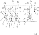
- Fig. 1 shows, in a highly schematic manner, a section from a gas engine with several cylinders 1.
- Each cylinder 1 has at least one gas exchange valve 2 on the inlet side and at least one gas exchange valve 3 on the outlet side.
- An ignitable mixture 4 of gaseous fuel 10 and combustion air 8 can be supplied to the respective cylinder 1 via the respective inlet-side gas exchange valve 2, this mixture 4 consisting of the gaseous fuel 10 and the combustion air 8 in the cylinders 1 is ignited and burned.
- Exhaust gas 5 produced in this case can be discharged from cylinders 1 via the gas exchange valves 3 on the outlet side and guided via an exhaust gas line 6 in the direction of an exhaust gas aftertreatment system (not shown).
- Fig. 1 shows a combustion air line 7, via which combustion air 8 can be guided in the direction of the cylinder 1.
- combustion air 8 it is not pure combustion air 8 that is guided in the direction of the cylinder 1 via the combustion air line 7, but rather a premix 9 of combustion air 8 and gaseous fuel 10, which is non-ignitable.
- the mixing ratio of this premix 9 of gaseous fuel 8 and combustion air 10 is accordingly below what is known as an explosion limit.
- Fig. 1 shows a metering device 11, via which the combustion air 8 can be metered in gaseous fuel 10 in a common mixing ratio of gaseous fuel 10 and combustion air 8 for all cylinders 1 that are supplied with combustion air 8 via the combustion air line 7.
- Fig. 1 also shows a gas line 12, via which gaseous fuel 10 can be conducted in the direction of the individual cylinders 1, around the gaseous fuel 10 conducted via the gas line 12 in the direction of the cylinder 1 upstream of the respective inlet-side gas exchange valve 2 of the respective cylinder 1 in the area a branch 13 branching off from the combustion air line 7, which leads to the respective cylinder 1, to be mixed with the premix 9.
- a gas valve 14 is assigned to each cylinder 1, via which further gaseous fuel 10 can be metered individually for each cylinder into the premix 9 of combustion air 8 and gaseous fuel 10, namely in the area of the cylinder 1 branching off from the combustion air line 7 Branch 13 immediately upstream of the respective inlet-side gas exchange valve 2 of the respective cylinder 1.
- the combustion air line 7 leading to the cylinders 1 not exclusively convey combustion air 8, but rather a non-ignitable premix 9 of gaseous fuel 10 and combustion air 8.
- This premix 9 is identical for all cylinders 1 .
- the mixing ratio of the premix 9 of combustion air 8 and gaseous fuel 10 is determined depending on the energy content of the gaseous fuel 10 in such a way that the premix 9 is non-ignitable, the mixing ratio of which is below what is known as an explosion limit. This enables the engine to be operated safely and efficiently.
- the energy content of the mixture 4 of gaseous fuel 10 and combustion air 8 to be burned in the cylinder 1 is no longer dependent on the maximum opening duration of the gas valves 14, but can rather be increased by the mixing ratio of the premix 9. This enables stable operation of the engine, particularly when a gaseous fuel with low energy content is to be burned.
Landscapes
- Engineering & Computer Science (AREA)
- Chemical & Material Sciences (AREA)
- Combustion & Propulsion (AREA)
- Mechanical Engineering (AREA)
- General Engineering & Computer Science (AREA)
- Chemical Kinetics & Catalysis (AREA)
- General Chemical & Material Sciences (AREA)
- Oil, Petroleum & Natural Gas (AREA)
- Output Control And Ontrol Of Special Type Engine (AREA)
- Combustion Methods Of Internal-Combustion Engines (AREA)
- Electrical Control Of Air Or Fuel Supplied To Internal-Combustion Engine (AREA)
Abstract
Description
- Die Erfindung betrifft ein Verfahren zum Betreiben eines Gasmotors oder eines in einem Gaskraftstoffbetriebsmodus betriebenen Dual-Fuel-Motors.
- Bei einem Dual-Fuel-Motor handelt es sich um eine Brennkraftmaschine, in welcher sowohl gasförmiger Kraftstoff in einem Gaskraftstoffbetriebsmodus als auch flüssiger Kraftstoff in einem Flüssigkraftstoffbetriebsmodus verbrannt werden kann. Im Flüssigkraftstoffbetriebsmodus wird den Zylindern flüssiger Kraftstoff, wie zum Beispiel Schweröl, über Kraftstoffinjektoren zugeführt, wobei der flüssige Kraftstoff unter Anwesenheit von Verbrennungsluft, die den Zylindern über einlassseitige Gaswechselventile zugeführt wird, verbrannt wird. Hierbei entstehendes Abgas wird über auslassseitige Gaswechselventile abgeführt. Im Gaskraftstoffbetriebsmodus wird in den Zylindern eines Dual-Fuel-Motors gasförmiger Kraftstoff, wie zum Beispiel Erdgas, verbrannt. Dabei wird den Zylindern ein Gemisch aus gasförmigem Kraftstoff und Verbrennungsluft über die einlassseitigen Gaswechselventile zugeführt, wobei Abgas wiederum über die auslassseitigen Gaswechselventile von abgeführt wird. Zur Zündung des Gemischs aus gasförmigem Kraftstoff und Verbrennungsluft im Gaskraftstoffbetriebsmodus dient bei Dual-Fuel-Motoren Zündöl. Bei dem Zündöl handelt es sich um den flüssigen Kraftstoff, der im Flüssigkraftstoffbetriebsmodus verbrannt wird. Abhängig von der Ausführung der Kraftstoffinjektoren kann im Gaskraftstoffbetriebsmodus der als Zündöl dienende flüssige Kraftstoff den Zylindern über dieselben Kraftstoffinjektoren zugeführt werden, über die im Flüssigkraftstoffbetriebsmodus der flüssige Kraftstoff den Zylindern zugeführt wird. Es ist jedoch auch möglich, den Zylindern separate Zündöl-Injektoren zuzuordnen, über die im Gaskraftstoffbetriebsmodus der als Zündöl dienende, flüssige Kraftstoff den Zylindern zugeführt wird.
- In einem Gasmotor wird ausschließlich gasförmiger Kraftstoff verbrannt, wobei den Zylindern eines Gasmotors über die einlassseitigen Gaswechselventile ein Gemisch aus gasförmigem Kraftstoff und Verbrennungsluft zugeführt wird. Dieses Gemisch aus gasförmigem Kraftstoff und Verbrennungsluft wird bei einem Gasmotor über eine Zündkerze gezündet.
- Sowohl bei einem Gasmotor als auch bei einem im Gaskraftstoffbetriebsmodus betriebenen Dual-Fuel-Motor wird den Zylindern des Motors demnach ein Gemisch aus einem gasförmigen Kraftstoff und Verbrennungsluft zugeführt, in den Zylindern gezündet und verbrannt. Das Gemisch aus dem gasförmigen Kraftstoff und der Verbrennungsluft wird für den jeweiligen Zylinder dadurch bereitgestellt, dass der Verbrennungsluft, die über eine Verbrennungsluftleitung in Richtung auf die Zylinder geführt wird, stromaufwärts des einlassseitigen Gaswechselventils des jeweiligen Zylinders gasförmiger Kraftstoff zudosiert wird, und zwar über ein dem jeweiligen Zylinder zugeordnetes Gasventil zylinderindividuell.
- Die über das jeweilige Gasventil der Verbrennungsluft zudosierbare Menge an gasförmigem Kraftstoff ist dabei von der maximalen Öffnungsdauer des jeweiligen Gasventils abhängig. Die maximal zudosierbare Gasmenge korreliert dabei mit dem maximalen Energieinhalt des dem jeweiligen Zylinder zugeführten Gemischs aus gasförmigem Kraftstoff und Verbrennungsluft. Verfügt der gasförmige Kraftstoff über einen geringen Heizwert und demnach über einen geringen Energiegehalt, so kann es unter Umständen sein, dass der Energieinhalt des im Zylinder zu verbrennenden Gemischs aus gasförmigem Kraftstoff und Verbrennungsluft für eine stabile Verbrennung nicht ausreichend hoch ist.
- Es besteht Bedarf daran, einen Gasmotor oder einen in einem Gaskraftstoffbetriebsmodus betriebenen Dual-Fuel-Motor mit einer stabileren Verbrennung zu betreiben.
- Hiervon ausgehend liegt der Erfindung die Aufgabe zugrunde, ein neuartiges Verfahren zum Betreiben eines Gasmotors oder eines in einem Gaskraftstoffbetriebsmodus betriebenen Dual-Fuel-Motors zu schaffen. Diese Aufgabe wird durch ein Verfahren nach Anspruch 1 gelöst. Erfindungsgemäß wird über die Verbrennungsluftleitung ein nicht-zündfähiges Vorgemisch aus Verbrennungsluft und gasförmigem Kraftstoff in Richtung auf die Zylinder geführt. Dem nicht-zündfähigen Vorgemisch aus Verbrennungsluft und gasförmigem Kraftstoff wird stromaufwärts des einlassseitigen Gaswechselventils über das dem jeweiligen Zylinder zugeordnete Gasventil weiterer gasförmiger Kraftstoff zylinderindividuell zudosiert, um das nicht-zündfähige Vorgemisch aus Verbrennungsluft und gasförmigem Kraftstoff in das zündfähige Gemisch aus Verbrennungsluft und gasförmigem Kraftstoff zu wandeln.
- Bei dem erfindungsgemäßen Verfahren wird über die Verbrennungsluftleitung nicht reine Verbrennungsluft in Richtung auf die Zylinder geführt, sondern vielmehr ein nicht-zündfähiges Vorgemisch aus Verbrennungsluft und gasförmigem Kraftstoff, dessen Energieinhalt unterhalb einer sogenannten Explosionsgrenze für das Gemisch aus Verbrennungsluft und gasförmigem Kraftstoff liegt. Diesem für die Zylinder gleichen Vorgemisch aus Verbrennungsluft und gasförmigem Kraftstoff wird zylinderindividuell stromaufwärts des jeweiligen einlassseitigen Gaswechselventils über das dem jeweiligen Zylinder zugeordnete Gasventil zylinderindividuell gasförmiger Kraftstoff zudosiert, um so das nicht-zündfähige Vorgemisch aus Verbrennungsluft und gasförmigem Kraftstoff in das zündfähige Gemisch aus Verbrennungsluft und gasförmigem Kraftstoff zu wandeln. Der maximale Energieinhalt eines in einem Zylinder zu verbrennenden Gemischs aus Verbrennungsluft und gasförmigem Kraftstoff wird demnach nicht mehr durch die maximale Öffnungsdauer des Gasventils begrenzt, vielmehr kann dieser Energieinhalt dadurch erhöht werden, dass über die Verbrennungsluftleitung das Vorgemisch aus gasförmigem Kraftstoff und Verbrennungsluft geführt wird, welches jedoch noch nicht zündfähig ist, dessen Mischungsverhältnis also unter der Explosionsgrenze des Gemischs aus gasförmigem Kraftstoff und Verbrennungsluft liegt.
- Nach einer vorteilhaften Weiterbildung wird das Mischungsverhältnis des nicht-zündfähigen Vorgemischs aus Verbrennungsluft und gasförmigem Kraftstoff abhängig von Energiegehalt des gasförmigen Kraftstoffs eingestellt. Mit dieser Weiterbildung der Erfindung ist ein sicherer und effizienter Betrieb des jeweiligen Motors möglich. Das Mischungsverhältnis des über die Verbrennungsluftleitung zu führenden Vorgemischs aus Verbrennungsluft und gasförmigem Kraftstoff wird abhängig vom Energieinhalt des gasförmigen Kraftstoffs so eingestellt, dass dasselbe nicht zündfähig ist.
- Bevorzugte Weiterbildungen der Erfindung ergeben sich aus den Unteransprüchen und der nachfolgenden Beschreibung. Ausführungsbeispiele der Erfindung werden, ohne hierauf beschränkt zu sein, an Hand der Zeichnung näher erläutert. Dabei zeigt:
- Fig. 1
- eine stark schematisierte Ansicht einer erfindungsgemäßen Brennkraftmaschine zur Verdeutlichung des erfindungsgemäßen Verfahrens.
-
Fig. 1 zeigt stark schematisiert einen Ausschnitt aus einem Gasmotor mit mehreren Zylindern 1. - Jeder Zylinder 1 verfügt über mindestens ein einlassseitiges Gaswechselventil 2 und mindestens ein auslassseitiges Gaswechselventil 3. Über das jeweilige einlassseitige Gaswechselventil 2 kann dem jeweiligen Zylinder 1 ein zündfähiges Gemisch 4 aus gasförmigem Kraftstoff 10 und Verbrennungsluft 8 zugeführt werden, wobei dieses Gemisch 4 aus dem gasförmigen Kraftstoff 10 und der Verbrennungsluft 8 in den Zylindern 1 gezündet und verbrannt wird. Hierbei entstehendes Abgas 5 kann über die auslassseitigen Gaswechselventile 3 von den Zylindern 1 abgeführt und über eine Abgasleitung 6 in Richtung auf ein Abgasnachbehandlungssystem (nicht gezeigt) geführt werden.
- Bei dem Gemisch 4 aus dem gasförmigen Kraftstoff 10 und der Verbrennungsluft 8, welches den Zylindern 1 über die einlassseitigen Gaswechselventile 2 zugeführt wird, handelt es sich um ein zündfähiges Gemisch 4 aus Gas und Verbrennungsluft, welches bei einem Gasmotor mithilfe einer Zündkerze des jeweiligen Zylinders 1 gezündet wird.
-
Fig. 1 zeigt eine Verbrennungsluftleitung 7, über die Verbrennungsluft 8 in Richtung auf die Zylinder 1 geführt werden kann. Dabei wird über die Verbrennungsluftleitung 7 nicht reine Verbrennungsluft 8 in Richtung auf die Zylinder 1 geführt, sondern vielmehr eine Vorgemisch 9 aus Verbrennungsluft 8 und gasförmigem Kraftstoff 10, welches nicht-zündfähig ist. Das Mischungsverhältnis dieses Vorgemischs 9 aus gasförmigem Kraftstoff 8 und Verbrennungsluft 10 liegt demnach unterhalb einer sogenannten Explosionsgrenze. -
Fig. 1 zeigt eine Dosiereinrichtung 11, über die der Verbrennungsluft 8 gasförmiger Kraftstoff 10 zudosiert werden kann, und zwar in einem für alle Zylinder 1, die über die Verbrennungsluftleitung 7 mit Verbrennungsluft 8 versorgt werden, gemeinsamen Mischungsverhältnis aus gasförmigem Kraftstoff 10 und Verbrennungsluft 8. -
Fig. 1 zeigt weiterhin eine Gasleitung 12, über die gasförmiger Kraftstoff 10 in Richtung auf die einzelnen Zylinder 1 geführt werden kann, um den über die Gasleitung 12 in Richtung auf die Zylinder 1 geführten gasförmigen Kraftstoff 10 stromaufwärts des jeweiligen einlassseitigen Gaswechselventils 2 des jeweiligen Zylinders 1 im Bereich einer von der Verbrennungsluftleitung 7 abzweigenden Abzweigung 13, die zum jeweiligen Zylinder 1 führt, mit dem Vorgemisch 9 zu mischen. - Durch die Mischung des Vorgemischs 9 aus Verbrennungsluft 8 und gasförmigem Kraftstoff 10 mit dem über die Gasleitung 12 geführten weiteren gasförmigen Kraftstoff 10 entsteht das Gemisch 4 aus gasförmigem Kraftstoff 10 und Verbrennungsluft 8, welches zündfähig ist.
-
Fig. 1 kann entnommen werden, dass jedem Zylinder 1 ein Gasventil 14 zugeordnet ist, über welches dem Vorgemisch 9 aus Verbrennungsluft 8 und gasförmigem Kraftstoff 10 zylinderindividuell weiterer gasförmiger Kraftstoff 10 zudosiert werden kann, nämlich im Bereich der von der Verbrennungsluftleitung 7 abzweigenden, zum jeweiligen Zylinder 1 führenden Abzweigung 13 unmittelbar stromaufwärts des jeweiligen einlassseitigen Gaswechselventils 2 des jeweiligen Zylinders 1. - Mit der hier vorliegenden Erfindung wird demnach vorgeschlagen, über die zu den Zylindern 1 führende Verbrennungsluftleitung 7 nicht ausschließlich Verbrennungsluft 8 zu führen, sondern vielmehr ein nicht-zündfähiges Vorgemisch 9 aus gasförmigem Kraftstoff 10 und Verbrennungsluft 8. Dieses Vorgemisch 9 ist für alle Zylinder 1 identisch.
- Stromaufwärts des jeweiligen Zylinders 1 wird diesem Vorgemisch 9 aus Verbrennungsluft 8 und gasförmigem Kraftstoff 10 weiterer gasförmiger Kraftstoff 10 zudosiert, nämlich über das dem jeweiligen Zylinder 1 zugeordnete Gasventil 14, über welches dem jeweiligen Zylinder 1 zylinderindividuell unmittelbar stromaufwärts des jeweiligen einlassseitigen Gaswechselventils 2 weiterer gasförmiger Kraftstoff 10 zugeführt werden kann, um das Vorgemisch 9 in ein zündfähiges Gemisch 4 aus gasförmigem Kraftstoff 10 und Verbrennungsluft 8 zu wandeln.
- Das Mischungsverhältnis des Vorgemischs 9 aus Verbrennungsluft 8 und gasförmigem Kraftstoff 10 wird abhängig vom Energieinhalt des gasförmigen Kraftstoffs 10 bestimmt, und zwar derart, dass das Vorgemisch 9 nicht-zündfähig ist, dessen Mischungsverhältnis also unter einer sogenannten Explosionsgrenze liegt. Hiermit kann der Motor sicher und effizient betrieben werden.
- Der Energieinhalt des im Zylinder 1 zu verbrennenden Gemischs 4 aus gasförmigem Kraftstoff 10 und Verbrennungsluft 8 ist nicht mehr von der maximalen Öffnungsdauer der Gasventile 14 abhängig, sondern kann vielmehr durch das Mischungsverhältnis des Vorgemischs 9 erhöht werden. Hiermit ist insbesondere dann, wenn ein gasförmiger Kraftstoff mit geringem Energieinhalt verbrannt werden soll, ein stabiler Betrieb des Motors möglich.
-
- 1
- Zylinder
- 2
- einlassseitiges Gaswechselventil
- 3
- auslassseitiges Gaswechselventil
- 4
- Gemisch
- 5
- Abgas
- 6
- Abgasleitung
- 7
- Verbrennungsluftleitung
- 8
- Verbrennungsluft
- 9
- Vorgemisch
- 10
- gasförmiger Kraftstoff
- 11
- Dosiereinrichtung
- 12
- Gasleitung
- 13
- Abzweigung
- 14
- Gasventil
Claims (5)
- Verfahren zum Betreiben eines Gasmotors oder eines in einem Gaskraftstoffbetriebsmodus betriebenen Dual-Fuel-Motors mit mehreren Zylindern,wobei in den Zylindern (1) des Gasmotors oder des Dual-Fuel-Motors ein zündfähiges Gemisch (4) aus einem gasförmigen Kraftstoff (10) und Verbrennungsluft (8) gezündet und verbrannt wird,wobei das zündfähige Gemisch (4) aus dem gasförmigen Kraftstoff (10) und der Verbrennungsluft (8) für den jeweiligen Zylinder dadurch bereitgestellt wird, dass Verbrennungsluft (8), die über eine Verbrennungsluftleitung (7) in Richtung auf die Zylinder (1) geführt wird, stromaufwärts eines einlassseitigen Gaswechselventils (2) des jeweiligen Zylinders (1) mit dem gasförmigem Kraftstoff (10) gemischt wird, welcher über ein dem jeweiligen Zylinder (1) zugeordnetes Gasventil (14) zylinderindividuell zudosiert wird,dadurch gekennzeichnet, dassüber die Verbrennungsluftleitung (7) ein nicht-zündfähiges Vorgemisch (9) aus der Verbrennungsluft (8) und dem gasförmigem Kraftstoff (10) in Richtung auf die Zylinder (1) geführt wird,dem nicht-zündfähigen Vorgemisch (9) aus Verbrennungsluft (8) und gasförmigem Kraftstoff (10) stromaufwärts des einlassseitigen Gaswechselventils (2) über das dem jeweiligen Zylinder (1) zugeordnete Gasventil (14) weiterer gasförmiger Kraftstoff (10) zylinderindividuell zudosiert wird, um das nicht-zündfähige Vorgemisch (9) aus Verbrennungsluft (8) und gasförmigem Kraftstoff (10) in das zündfähige Gemisch (4) aus Verbrennungsluft (8) und gasförmigem Kraftstoff (10) zu wandeln.
- Verfahren nach Anspruch 1, dadurch gekennzeichnet, dass das Mischungsverhältnis des nicht-zündfähigen Vorgemischs (9) aus Verbrennungsluft (8) und gasförmigem Kraftstoff (10) abhängig von Energiegehalt des gasförmigen Kraftstoffs (10) eingestellt wird.
- Verfahren nach Anspruche 1 oder 2, dadurch gekennzeichnet, dass das Mischungsverhältnis aus Verbrennungsluft (8) und gasförmigem Kraftstoff (10) des nicht-zündfähigen Vorgemischs (9) für alle Zylinder (1) gemeinsam eingestellt wird.
- Gasmotor oder Dual-Fuel-Motor,mit mehreren Zylindern (1), die einlassseitige Gaswechselventile (2) und auslassseitige Gaswechselventile (3) aufweisen,mit einer Verbrennungsluftleitung (7), über die Verbrennungsluft (8) in Richtung auf die einlassseitigen Gaswechselventile (2) der Zylinder (1) führbar ist,mit von der Verbrennungsluftleitung (7) zu den einlassseitigen Gaswechselventilen (2) der Zylinder (1) führenden Abzweigungen (13),mit einer Gasleitung (12) und mit den Zylindern (1) zugeordneten Gasventilen (14), über welche stromaufwärts des jeweiligen einlassseitigen Gaswechselventils (2) des Zylinders (1) die zum jeweiligen Zylinder (1) geführte Verbrennungsluft (8) mit gasförmigem Kraftstoff (10) mischbar ist, um dem jeweiligen Zylinder (1) ein zündfähiges Gemisch (4) aus dem gasförmigen Kraftstoff (10) und Verbrennungsluft (8) bereitzustellen, welches in den Zylindern (1) zündbar und verbrennbar ist,dadurch gekennzeichnet, dassüber die Verbrennungsluftleitung (7) ein nicht-zündfähiges Vorgemisch (9) aus Verbrennungsluft (8) und gasförmigem Kraftstoff (10) in Richtung auf die Zylinder (1) führbar ist,dem nicht-zündfähigen Vorgemisch (9) aus Verbrennungsluft (8) und gasförmigem Kraftstoff (10) stromaufwärts des einlassseitigen Gaswechselventils (2) über das dem jeweiligen Zylinder (1) zugeordnete Gasventil (14) weiterer gasförmiger Kraftstoff (8) zylinderindividuell zudosier bar ist, um das nicht-zündfähige Vorgemisch (9) aus Verbrennungsluft (8) und gasförmigem Kraftstoff (10) in das zündfähige Gemisch (4) aus Verbrennungsluft (8) und gasförmigem Kraftstoff (10) zu wandeln.
- Gasmotor oder Dual-Fuel-Motor nach Anspruch 4, gekennzeichnet durch eine der Verbrennungsluftleitung (7) zugeordnete Dosiereinrichtung (11) für gasförmigen Kraftstoff (10), über die das Mischungsverhältnis aus Verbrennungsluft (8) und gasförmigem Kraftstoff (10) des nicht-zündfähigen Vorgemischs (9) für alle Zylinder (19 gemeinsam einstellbar ist.
Applications Claiming Priority (1)
| Application Number | Priority Date | Filing Date | Title |
|---|---|---|---|
| DE102019102887.6A DE102019102887A1 (de) | 2019-02-06 | 2019-02-06 | Verfahren zum Betreiben eines Gasmotors oder eines in einem Gaskraftstoffbetriebsmodus betriebenen Dual-Fuel-Motors sowie entsprechender Motor |
Publications (1)
| Publication Number | Publication Date |
|---|---|
| EP3693587A1 true EP3693587A1 (de) | 2020-08-12 |
Family
ID=68621131
Family Applications (1)
| Application Number | Title | Priority Date | Filing Date |
|---|---|---|---|
| EP19210235.8A Withdrawn EP3693587A1 (de) | 2019-02-06 | 2019-11-20 | Verfahren zum betreiben eines gasmotors oder eines in einem gaskraftstoffbetriebsmodus betriebenen dual-fuel-motors sowie entsprechender motor |
Country Status (7)
| Country | Link |
|---|---|
| US (1) | US20200248652A1 (de) |
| EP (1) | EP3693587A1 (de) |
| JP (1) | JP2020128748A (de) |
| KR (1) | KR20200096881A (de) |
| CN (1) | CN111535922A (de) |
| CA (1) | CA3071171A1 (de) |
| DE (1) | DE102019102887A1 (de) |
Citations (4)
| Publication number | Priority date | Publication date | Assignee | Title |
|---|---|---|---|---|
| EP2143930A1 (de) * | 2007-12-14 | 2010-01-13 | Mitsubishi Heavy Industries, Ltd. | Steuerverfahren für ein gasmotorensystem und besagtes system |
| US20100275891A1 (en) * | 2008-02-18 | 2010-11-04 | Friedrich Gruber | Internal combustion engine |
| EP2620629A1 (de) * | 2011-01-31 | 2013-07-31 | Mitsubishi Heavy Industries, Ltd. | Brenngaszufuhrverfahren und -vorrichtung für einen gasmotor |
| DE102016218912A1 (de) * | 2016-09-29 | 2018-03-29 | Robert Bosch Gmbh | Kostengünstiges und energiesparendes Kraftstoffeinspritzsystem |
Family Cites Families (6)
| Publication number | Priority date | Publication date | Assignee | Title |
|---|---|---|---|---|
| DE10339854A1 (de) * | 2003-08-29 | 2005-03-24 | Daimlerchrysler Ag | Brennkraftmaschine |
| DE102004043934A1 (de) * | 2004-09-11 | 2006-03-30 | Daimlerchrysler Ag | Verfahren zum Betrieb einer Brennkraftmaschine |
| KR20090056104A (ko) * | 2007-11-29 | 2009-06-03 | (주)신유 | 듀얼 연료를 이용한 발전장치 및 이의 구동방법 |
| CN204299708U (zh) * | 2014-11-04 | 2015-04-29 | 吉林大学 | 一种缸内直喷双气体燃料点燃式燃烧及控制装置 |
| JP6793824B2 (ja) * | 2017-05-11 | 2020-12-09 | 株式会社Ihi原動機 | エンジンの制御方法及びエンジンシステム |
| CN109184926B (zh) * | 2018-07-24 | 2020-11-20 | 哈尔滨工程大学 | 一种基于双针阀喷油器的双燃料发动机燃烧装置及方法 |
-
2019
- 2019-02-06 DE DE102019102887.6A patent/DE102019102887A1/de not_active Ceased
- 2019-11-20 EP EP19210235.8A patent/EP3693587A1/de not_active Withdrawn
-
2020
- 2020-02-04 JP JP2020016996A patent/JP2020128748A/ja active Pending
- 2020-02-05 US US16/782,854 patent/US20200248652A1/en not_active Abandoned
- 2020-02-05 CA CA3071171A patent/CA3071171A1/en active Pending
- 2020-02-06 CN CN202010081586.4A patent/CN111535922A/zh active Pending
- 2020-02-06 KR KR1020200014177A patent/KR20200096881A/ko not_active Abandoned
Patent Citations (4)
| Publication number | Priority date | Publication date | Assignee | Title |
|---|---|---|---|---|
| EP2143930A1 (de) * | 2007-12-14 | 2010-01-13 | Mitsubishi Heavy Industries, Ltd. | Steuerverfahren für ein gasmotorensystem und besagtes system |
| US20100275891A1 (en) * | 2008-02-18 | 2010-11-04 | Friedrich Gruber | Internal combustion engine |
| EP2620629A1 (de) * | 2011-01-31 | 2013-07-31 | Mitsubishi Heavy Industries, Ltd. | Brenngaszufuhrverfahren und -vorrichtung für einen gasmotor |
| DE102016218912A1 (de) * | 2016-09-29 | 2018-03-29 | Robert Bosch Gmbh | Kostengünstiges und energiesparendes Kraftstoffeinspritzsystem |
Also Published As
| Publication number | Publication date |
|---|---|
| CA3071171A1 (en) | 2020-08-06 |
| RU2019141659A (ru) | 2021-06-16 |
| DE102019102887A1 (de) | 2020-08-06 |
| JP2020128748A (ja) | 2020-08-27 |
| CN111535922A (zh) | 2020-08-14 |
| US20200248652A1 (en) | 2020-08-06 |
| KR20200096881A (ko) | 2020-08-14 |
Similar Documents
| Publication | Publication Date | Title |
|---|---|---|
| DE102015206074B4 (de) | Brennkraftmaschine und Verfahren zum Betreiben einer Brennkraftmaschine | |
| DE3781276T2 (de) | Einen weiten bereich gasfoermiger brennstoffe ueberdeckendes verbrennungssystem fuer gasturbinen. | |
| DE112011105137B4 (de) | Steuersystem für einen Mehrkraftstoff-Verbrennungszylinder | |
| EP3267017B1 (de) | Verfahren zum betreiben eines dual-fuel grossdieselmotors sowie grossdieselmotor | |
| DE112012004984T5 (de) | Motor, der mehrere Kraftstoffe nutzt, und zugehöriges Verfahren | |
| EP2942504B1 (de) | Hubkolbenbrennkraftmaschine sowie Verfahren zum Betreiben einer Hubkolbenbrennkraftmaschine | |
| DE102008043930A1 (de) | Kraftstoff-Einspritzanlage für eine Brennkraftmaschine | |
| DE102016118591A1 (de) | Benzin-diesel-kombinations-verbrennungsmotor | |
| DE102015203607B4 (de) | Brennkraftmaschine sowie Verfahren zum Betreiben einer Brennkraftmaschine | |
| DE10339854A1 (de) | Brennkraftmaschine | |
| EP3872330A1 (de) | Verfahren zum betreiben eines grossdieselmotors, sowie grossdieselmotor | |
| EP0002819A1 (de) | Verfahren zur Verbesserung von Verbrennungsprozessen | |
| DE3504699A1 (de) | Wasserbeimischung zum dieselkraftstoff bei dieselmotoren kurz vor der einspritzpumpe | |
| DE102019102887A1 (de) | Verfahren zum Betreiben eines Gasmotors oder eines in einem Gaskraftstoffbetriebsmodus betriebenen Dual-Fuel-Motors sowie entsprechender Motor | |
| EP3896267A1 (de) | Längsgespülter grossmotor | |
| DE102018222525B4 (de) | Verfahren zum Betreiben einer Brennkraftmaschine und Brennkraftmaschine zur Durchführung eines solchen Verfahrens | |
| DE102019112068B4 (de) | Verfahren zum Betreiben eines Gasmotors oder eines in einem Gaskraftstoffbetriebsmodus betriebenen Dual-Fuel-Motors | |
| DE10214987B4 (de) | Verbrennungsmotor und Verfahren zum Erzeugen von Bewegungsenergie aus kohlenwasserstoffhaltigen Kraftstoffen | |
| DE102013111249B4 (de) | Verbrennungsmotor | |
| DE102019126365B3 (de) | Brennkraftmaschine eines Kraftfahrzeugs und Verfahren zum Betreiben derselben | |
| DE19737764C2 (de) | DPI Kraftstoffaufbereitungsanlage für mobile und stationäre Verbrennungsmotoren | |
| DE102006035077A1 (de) | Fremdgezündete Brennkraftmaschine für gasförmige Kraftstoffe und Verfahren zum Betrieb der Brennkraftmaschine | |
| DE102017211226B4 (de) | Verfahren zum Betreiben einer Brennkraftmaschine und Brennkraftmaschine | |
| DE615102C (de) | Einrichtung zur Speisung und Zuendung von Brennkraftmaschinen mit Leicht- und Schwerkraftstoff | |
| WO2000052321A1 (de) | Kraftstoffaufbereitungsanlage für mobile und stationäre verbrennungsmotoren |
Legal Events
| Date | Code | Title | Description |
|---|---|---|---|
| PUAI | Public reference made under article 153(3) epc to a published international application that has entered the european phase |
Free format text: ORIGINAL CODE: 0009012 |
|
| STAA | Information on the status of an ep patent application or granted ep patent |
Free format text: STATUS: THE APPLICATION HAS BEEN PUBLISHED |
|
| AK | Designated contracting states |
Kind code of ref document: A1 Designated state(s): AL AT BE BG CH CY CZ DE DK EE ES FI FR GB GR HR HU IE IS IT LI LT LU LV MC MK MT NL NO PL PT RO RS SE SI SK SM TR |
|
| AX | Request for extension of the european patent |
Extension state: BA ME |
|
| STAA | Information on the status of an ep patent application or granted ep patent |
Free format text: STATUS: REQUEST FOR EXAMINATION WAS MADE |
|
| 17P | Request for examination filed |
Effective date: 20210129 |
|
| RBV | Designated contracting states (corrected) |
Designated state(s): AL AT BE BG CH CY CZ DE DK EE ES FI FR GB GR HR HU IE IS IT LI LT LU LV MC MK MT NL NO PL PT RO RS SE SI SK SM TR |
|
| STAA | Information on the status of an ep patent application or granted ep patent |
Free format text: STATUS: THE APPLICATION IS DEEMED TO BE WITHDRAWN |
|
| 18D | Application deemed to be withdrawn |
Effective date: 20210213 |