EP3693202A2 - Fuel cell vehicle - Google Patents
Fuel cell vehicle Download PDFInfo
- Publication number
- EP3693202A2 EP3693202A2 EP20151794.3A EP20151794A EP3693202A2 EP 3693202 A2 EP3693202 A2 EP 3693202A2 EP 20151794 A EP20151794 A EP 20151794A EP 3693202 A2 EP3693202 A2 EP 3693202A2
- Authority
- EP
- European Patent Office
- Prior art keywords
- central
- end portion
- fuel cell
- fuel tank
- stack frame
- Prior art date
- Legal status (The legal status is an assumption and is not a legal conclusion. Google has not performed a legal analysis and makes no representation as to the accuracy of the status listed.)
- Granted
Links
Images





Classifications
-
- B—PERFORMING OPERATIONS; TRANSPORTING
- B60—VEHICLES IN GENERAL
- B60L—PROPULSION OF ELECTRICALLY-PROPELLED VEHICLES; SUPPLYING ELECTRIC POWER FOR AUXILIARY EQUIPMENT OF ELECTRICALLY-PROPELLED VEHICLES; ELECTRODYNAMIC BRAKE SYSTEMS FOR VEHICLES IN GENERAL; MAGNETIC SUSPENSION OR LEVITATION FOR VEHICLES; MONITORING OPERATING VARIABLES OF ELECTRICALLY-PROPELLED VEHICLES; ELECTRIC SAFETY DEVICES FOR ELECTRICALLY-PROPELLED VEHICLES
- B60L50/00—Electric propulsion with power supplied within the vehicle
- B60L50/50—Electric propulsion with power supplied within the vehicle using propulsion power supplied by batteries or fuel cells
- B60L50/70—Electric propulsion with power supplied within the vehicle using propulsion power supplied by batteries or fuel cells using power supplied by fuel cells
- B60L50/71—Arrangement of fuel cells within vehicles specially adapted for electric vehicles
-
- B—PERFORMING OPERATIONS; TRANSPORTING
- B60—VEHICLES IN GENERAL
- B60K—ARRANGEMENT OR MOUNTING OF PROPULSION UNITS OR OF TRANSMISSIONS IN VEHICLES; ARRANGEMENT OR MOUNTING OF PLURAL DIVERSE PRIME-MOVERS IN VEHICLES; AUXILIARY DRIVES FOR VEHICLES; INSTRUMENTATION OR DASHBOARDS FOR VEHICLES; ARRANGEMENTS IN CONNECTION WITH COOLING, AIR INTAKE, GAS EXHAUST OR FUEL SUPPLY OF PROPULSION UNITS IN VEHICLES
- B60K15/00—Arrangement in connection with fuel supply of combustion engines or other fuel consuming energy converters, e.g. fuel cells; Mounting or construction of fuel tanks
- B60K15/03—Fuel tanks
-
- H—ELECTRICITY
- H01—ELECTRIC ELEMENTS
- H01M—PROCESSES OR MEANS, e.g. BATTERIES, FOR THE DIRECT CONVERSION OF CHEMICAL ENERGY INTO ELECTRICAL ENERGY
- H01M8/00—Fuel cells; Manufacture thereof
- H01M8/04—Auxiliary arrangements, e.g. for control of pressure or for circulation of fluids
- H01M8/04298—Processes for controlling fuel cells or fuel cell systems
- H01M8/04313—Processes for controlling fuel cells or fuel cell systems characterised by the detection or assessment of variables; characterised by the detection or assessment of failure or abnormal function
- H01M8/0432—Temperature; Ambient temperature
- H01M8/04365—Temperature; Ambient temperature of other components of a fuel cell or fuel cell stacks
-
- B—PERFORMING OPERATIONS; TRANSPORTING
- B60—VEHICLES IN GENERAL
- B60K—ARRANGEMENT OR MOUNTING OF PROPULSION UNITS OR OF TRANSMISSIONS IN VEHICLES; ARRANGEMENT OR MOUNTING OF PLURAL DIVERSE PRIME-MOVERS IN VEHICLES; AUXILIARY DRIVES FOR VEHICLES; INSTRUMENTATION OR DASHBOARDS FOR VEHICLES; ARRANGEMENTS IN CONNECTION WITH COOLING, AIR INTAKE, GAS EXHAUST OR FUEL SUPPLY OF PROPULSION UNITS IN VEHICLES
- B60K1/00—Arrangement or mounting of electrical propulsion units
- B60K1/04—Arrangement or mounting of electrical propulsion units of the electric storage means for propulsion
-
- B—PERFORMING OPERATIONS; TRANSPORTING
- B60—VEHICLES IN GENERAL
- B60L—PROPULSION OF ELECTRICALLY-PROPELLED VEHICLES; SUPPLYING ELECTRIC POWER FOR AUXILIARY EQUIPMENT OF ELECTRICALLY-PROPELLED VEHICLES; ELECTRODYNAMIC BRAKE SYSTEMS FOR VEHICLES IN GENERAL; MAGNETIC SUSPENSION OR LEVITATION FOR VEHICLES; MONITORING OPERATING VARIABLES OF ELECTRICALLY-PROPELLED VEHICLES; ELECTRIC SAFETY DEVICES FOR ELECTRICALLY-PROPELLED VEHICLES
- B60L3/00—Electric devices on electrically-propelled vehicles for safety purposes; Monitoring operating variables, e.g. speed, deceleration or energy consumption
- B60L3/0007—Measures or means for preventing or attenuating collisions
-
- B—PERFORMING OPERATIONS; TRANSPORTING
- B60—VEHICLES IN GENERAL
- B60L—PROPULSION OF ELECTRICALLY-PROPELLED VEHICLES; SUPPLYING ELECTRIC POWER FOR AUXILIARY EQUIPMENT OF ELECTRICALLY-PROPELLED VEHICLES; ELECTRODYNAMIC BRAKE SYSTEMS FOR VEHICLES IN GENERAL; MAGNETIC SUSPENSION OR LEVITATION FOR VEHICLES; MONITORING OPERATING VARIABLES OF ELECTRICALLY-PROPELLED VEHICLES; ELECTRIC SAFETY DEVICES FOR ELECTRICALLY-PROPELLED VEHICLES
- B60L50/00—Electric propulsion with power supplied within the vehicle
- B60L50/50—Electric propulsion with power supplied within the vehicle using propulsion power supplied by batteries or fuel cells
- B60L50/70—Electric propulsion with power supplied within the vehicle using propulsion power supplied by batteries or fuel cells using power supplied by fuel cells
- B60L50/72—Constructional details of fuel cells specially adapted for electric vehicles
-
- B—PERFORMING OPERATIONS; TRANSPORTING
- B60—VEHICLES IN GENERAL
- B60R—VEHICLES, VEHICLE FITTINGS, OR VEHICLE PARTS, NOT OTHERWISE PROVIDED FOR
- B60R19/00—Wheel guards; Radiator guards, e.g. grilles; Obstruction removers; Fittings damping bouncing force in collisions
- B60R19/02—Bumpers, i.e. impact receiving or absorbing members for protecting vehicles or fending off blows from other vehicles or objects
- B60R19/24—Arrangements for mounting bumpers on vehicles
- B60R19/26—Arrangements for mounting bumpers on vehicles comprising yieldable mounting means
- B60R19/34—Arrangements for mounting bumpers on vehicles comprising yieldable mounting means destroyed upon impact, e.g. one-shot type
-
- F—MECHANICAL ENGINEERING; LIGHTING; HEATING; WEAPONS; BLASTING
- F16—ENGINEERING ELEMENTS AND UNITS; GENERAL MEASURES FOR PRODUCING AND MAINTAINING EFFECTIVE FUNCTIONING OF MACHINES OR INSTALLATIONS; THERMAL INSULATION IN GENERAL
- F16F—SPRINGS; SHOCK-ABSORBERS; MEANS FOR DAMPING VIBRATION
- F16F7/00—Vibration-dampers; Shock-absorbers
- F16F7/12—Vibration-dampers; Shock-absorbers using plastic deformation of members
-
- H—ELECTRICITY
- H01—ELECTRIC ELEMENTS
- H01M—PROCESSES OR MEANS, e.g. BATTERIES, FOR THE DIRECT CONVERSION OF CHEMICAL ENERGY INTO ELECTRICAL ENERGY
- H01M8/00—Fuel cells; Manufacture thereof
- H01M8/04—Auxiliary arrangements, e.g. for control of pressure or for circulation of fluids
-
- H—ELECTRICITY
- H01—ELECTRIC ELEMENTS
- H01M—PROCESSES OR MEANS, e.g. BATTERIES, FOR THE DIRECT CONVERSION OF CHEMICAL ENERGY INTO ELECTRICAL ENERGY
- H01M8/00—Fuel cells; Manufacture thereof
- H01M8/04—Auxiliary arrangements, e.g. for control of pressure or for circulation of fluids
- H01M8/04298—Processes for controlling fuel cells or fuel cell systems
- H01M8/04313—Processes for controlling fuel cells or fuel cell systems characterised by the detection or assessment of variables; characterised by the detection or assessment of failure or abnormal function
- H01M8/04537—Electric variables
- H01M8/04544—Voltage
- H01M8/04559—Voltage of fuel cell stacks
-
- H—ELECTRICITY
- H01—ELECTRIC ELEMENTS
- H01M—PROCESSES OR MEANS, e.g. BATTERIES, FOR THE DIRECT CONVERSION OF CHEMICAL ENERGY INTO ELECTRICAL ENERGY
- H01M8/00—Fuel cells; Manufacture thereof
- H01M8/04—Auxiliary arrangements, e.g. for control of pressure or for circulation of fluids
- H01M8/04298—Processes for controlling fuel cells or fuel cell systems
- H01M8/04313—Processes for controlling fuel cells or fuel cell systems characterised by the detection or assessment of variables; characterised by the detection or assessment of failure or abnormal function
- H01M8/04537—Electric variables
- H01M8/04574—Current
- H01M8/04589—Current of fuel cell stacks
-
- B—PERFORMING OPERATIONS; TRANSPORTING
- B60—VEHICLES IN GENERAL
- B60K—ARRANGEMENT OR MOUNTING OF PROPULSION UNITS OR OF TRANSMISSIONS IN VEHICLES; ARRANGEMENT OR MOUNTING OF PLURAL DIVERSE PRIME-MOVERS IN VEHICLES; AUXILIARY DRIVES FOR VEHICLES; INSTRUMENTATION OR DASHBOARDS FOR VEHICLES; ARRANGEMENTS IN CONNECTION WITH COOLING, AIR INTAKE, GAS EXHAUST OR FUEL SUPPLY OF PROPULSION UNITS IN VEHICLES
- B60K1/00—Arrangement or mounting of electrical propulsion units
- B60K1/04—Arrangement or mounting of electrical propulsion units of the electric storage means for propulsion
- B60K2001/0405—Arrangement or mounting of electrical propulsion units of the electric storage means for propulsion characterised by their position
- B60K2001/0411—Arrangement in the front part of the vehicle
-
- B—PERFORMING OPERATIONS; TRANSPORTING
- B60—VEHICLES IN GENERAL
- B60K—ARRANGEMENT OR MOUNTING OF PROPULSION UNITS OR OF TRANSMISSIONS IN VEHICLES; ARRANGEMENT OR MOUNTING OF PLURAL DIVERSE PRIME-MOVERS IN VEHICLES; AUXILIARY DRIVES FOR VEHICLES; INSTRUMENTATION OR DASHBOARDS FOR VEHICLES; ARRANGEMENTS IN CONNECTION WITH COOLING, AIR INTAKE, GAS EXHAUST OR FUEL SUPPLY OF PROPULSION UNITS IN VEHICLES
- B60K1/00—Arrangement or mounting of electrical propulsion units
- B60K1/04—Arrangement or mounting of electrical propulsion units of the electric storage means for propulsion
- B60K2001/0405—Arrangement or mounting of electrical propulsion units of the electric storage means for propulsion characterised by their position
- B60K2001/0416—Arrangement in the rear part of the vehicle
-
- Y—GENERAL TAGGING OF NEW TECHNOLOGICAL DEVELOPMENTS; GENERAL TAGGING OF CROSS-SECTIONAL TECHNOLOGIES SPANNING OVER SEVERAL SECTIONS OF THE IPC; TECHNICAL SUBJECTS COVERED BY FORMER USPC CROSS-REFERENCE ART COLLECTIONS [XRACs] AND DIGESTS
- Y02—TECHNOLOGIES OR APPLICATIONS FOR MITIGATION OR ADAPTATION AGAINST CLIMATE CHANGE
- Y02T—CLIMATE CHANGE MITIGATION TECHNOLOGIES RELATED TO TRANSPORTATION
- Y02T10/00—Road transport of goods or passengers
- Y02T10/60—Other road transportation technologies with climate change mitigation effect
- Y02T10/70—Energy storage systems for electromobility, e.g. batteries
-
- Y—GENERAL TAGGING OF NEW TECHNOLOGICAL DEVELOPMENTS; GENERAL TAGGING OF CROSS-SECTIONAL TECHNOLOGIES SPANNING OVER SEVERAL SECTIONS OF THE IPC; TECHNICAL SUBJECTS COVERED BY FORMER USPC CROSS-REFERENCE ART COLLECTIONS [XRACs] AND DIGESTS
- Y02—TECHNOLOGIES OR APPLICATIONS FOR MITIGATION OR ADAPTATION AGAINST CLIMATE CHANGE
- Y02T—CLIMATE CHANGE MITIGATION TECHNOLOGIES RELATED TO TRANSPORTATION
- Y02T10/00—Road transport of goods or passengers
- Y02T10/60—Other road transportation technologies with climate change mitigation effect
- Y02T10/7072—Electromobility specific charging systems or methods for batteries, ultracapacitors, supercapacitors or double-layer capacitors
-
- Y—GENERAL TAGGING OF NEW TECHNOLOGICAL DEVELOPMENTS; GENERAL TAGGING OF CROSS-SECTIONAL TECHNOLOGIES SPANNING OVER SEVERAL SECTIONS OF THE IPC; TECHNICAL SUBJECTS COVERED BY FORMER USPC CROSS-REFERENCE ART COLLECTIONS [XRACs] AND DIGESTS
- Y02—TECHNOLOGIES OR APPLICATIONS FOR MITIGATION OR ADAPTATION AGAINST CLIMATE CHANGE
- Y02T—CLIMATE CHANGE MITIGATION TECHNOLOGIES RELATED TO TRANSPORTATION
- Y02T90/00—Enabling technologies or technologies with a potential or indirect contribution to GHG emissions mitigation
- Y02T90/10—Technologies relating to charging of electric vehicles
- Y02T90/14—Plug-in electric vehicles
Definitions
- the invention relates to a fuel cell vehicle, and particularly to a fuel cell vehicle including a stack frame that holds a fuel cell stack.
- JP 2017-144859 A describes a fuel cell vehicle configured such that a fuel cell stack is fixed on the upper side of a stack frame and provided in front of a vehicle cabin.
- the present inventors came up with a fuel cell vehicle in which a fuel tank is placed below an occupant in order to secure a space inside the vehicle and extend a cruising range, and the present inventors examined the fuel cell vehicle.
- the present inventors found the following problems about the above technique.
- the fuel tank When the fuel cell vehicle receives an impact due to a front-end collision or the like, the fuel tank might collide with a stack frame, so that the fuel tank might be damaged. In a case where the fuel tank collides with a corner of the stack frame, the fuel tank might be damaged.
- the present invention provides a fuel cell vehicle that restrains breakage of a fuel tank provided in a fuel cell vehicle when the fuel cell vehicle receives an impact and the fuel tank collides with a stack frame.
- a first aspect of the invention relates to a fuel cell vehicle including a stack frame and a fuel tank.
- the stack frame is configured such that a fuel cell stack is provided thereon, and the stack frame is placed in front of a vehicle cabin.
- the stack frame includes a central member, a right member joined to a right edge portion of the central member, a left member joined to a left edge portion of the central member, and a front cross member.
- the front cross member is joined to front edge portions of the central member, the right member, and the left member.
- the fuel tank is placed behind the stack frame.
- the right member and the left member hit the fuel tank first, so that the rear side of the left member and the rear side of the right member receive respective forces in respective directions to be separated from the central member.
- the front-end portion of the first joining portion between the central member and the right member and the front-end portion of the second joining portion between the central member and the left member overlap with the third joining portion of the front cross member with the front edge portions of the central member, the right member, and the left member.
- a rear-end portion of the first joining portion between the central member and the right member and a rear-end portion of the second joining portion between the central member and the left member serve as starting points of breaking, and the left member and the right member are separated from the central member and move to follow the movement of the fuel tank.
- the fuel tank can be hardly damaged in comparison with a case where the fuel tank collides with a corner of the stack frame. This can accordingly restrain the breakage of the fuel tank.
- a rear-end portion of the central member may be placed in front of a rear-end portion of the right member and a rear-end portion of the left member.
- the fuel tank may include a front-end portion having a width longer than a distance between the right member and the left member.
- the fuel tank easily hits the right member and the left member without hitting the central member, and the rear side of the left member and the rear side of the right member easily receive respective forces in respective directions to be separated from the central member. Accordingly, the left member and the right member are easily separated from the central member and easily move to follow the movement of the fuel tank, thereby resulting in that the fuel tank can be further hardly damaged.
- the fuel cell vehicle may further include a crash box placed in front of the front cross member.
- the crash box may be placed between an extension line of a join line between the central member and the right member and an extension line of a join line between the central member and the left member.
- the opposite ends of the front cross member deform to be separated from the right member and the left member. Accordingly, the left member and the right member easily move to follow the movement of the fuel tank, thereby resulting in that the fuel tank can be further hardly damaged.
- the mechanical strength of the first joining portion between the central member and the right member and the mechanical strength of the second joining portion between the central member and the left member may be lower than the mechanical strengths of an outer wall of the fuel tank, the right member, and the left member. Further, the mechanical strengths of the right member and the left member may be higher than the mechanical strength of an outer wall of the fuel tank.
- the front cross member deforms to be disjoined from the right member and the left member. Accordingly, the left member and the right member easily move to follow the movement of the fuel tank separated from the central member, thereby resulting in that the fuel tank can be further hardly damaged.
- a second aspect of the invention relates to a fuel cell vehicle including a stack frame and a fuel tank.
- the stack frame is configured such that a fuel cell stack is provided thereon, and the stack frame is placed behind a vehicle cabin.
- the stack frame includes a central member, a right member joined to a right edge portion of the central member, a left member joined to a left edge portion of the central member, and a rear cross member.
- the rear cross member is joined to rear edge portions of the central member, the right member, and the left member.
- the fuel tank is placed in front of the stack frame.
- the right member and the left member hit the fuel tank first, so that the front side of the left member and the front side of the right member receive respective forces in respective directions to be separated from the central member.
- the rear-end portion of the first joining portion between the central member and the right member and the rear-end portion of the second joining portion between the central member and the left member overlap with the third joining portion of the rear cross member with the rear edge portions of the central member, the right member, and the left member.
- a front-end portion of the first joining portion between the central member and the right member and a front-end portion of the second joining portion between the central member and the left member serve as starting points of breaking, and the left member and the right member are separated from the central member and move to follow the movement of the fuel tank.
- the fuel tank can be hardly damaged in comparison with a case where the fuel tank collides with a corner of the stack frame. This makes it possible to restrain a breakage of the fuel tank.
- FIG. 1 is a schematic view illustrating a fuel cell vehicle according to the first embodiment.
- FIG. 2 is a top view illustrating one concrete example of a configuration of an essential part of the fuel cell vehicle according to the first embodiment.
- FIG. 3 is a top view schematically illustrating the configuration of the essential part of the fuel cell vehicle according to the first embodiment.
- FIG. 4 is a side view schematically illustrating the configuration of the essential part of the fuel cell vehicle according to the first embodiment.
- FIG. 4 is a side view schematically illustrating the configuration of the essential part of the fuel cell vehicle illustrated in FIG. 3 .
- FIG. 1 is a schematic view illustrating a fuel cell vehicle according to the first embodiment.
- FIG. 2 is a top view illustrating one concrete example of a configuration of an essential part of the fuel cell vehicle according to the first embodiment.
- FIG. 3 is a top view schematically illustrating the configuration of the essential part of the fuel cell vehicle according to the first embodiment.
- FIG. 4 is a side view schematically illustrating the configuration of
- FIG. 5 is a top view schematically illustrating an operation of the essential part in a case where the fuel cell vehicle according to the first embodiment has a collision.
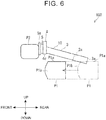
- FIG. 6 is a side view schematically illustrating the operation of the essential part in a case where the fuel cell vehicle according to the first embodiment has a collision.
- FIG. 1 is a view of a fuel cell vehicle 501 when the fuel cell vehicle 501 is viewed from above.
- FIGS. 2 , 3 , and 5 are views of a stack frame 100 when the stack frame 100 is viewed from above.
- FIGS. 4 and 6 are views of the stack frame 100 when the stack frame 100 is viewed from its left side.
- the stack frame 100, a fuel tank P1, and a vehicle component P2 are illustrated in a continuous line.
- the fuel cell vehicle 501 includes a front-side compartment 501a, a vehicle cabin 501b, and a rear-side compartment 501c.
- the front-side compartment 501a is placed in front of the vehicle cabin 501b
- the rear-side compartment 501c is placed behind the vehicle cabin 501b.
- the vehicle cabin 501b is a space where an occupant is seated.
- the fuel cell vehicle 501 includes four wheels (not shown), for example, and the four wheels are provided at four corners of the fuel cell vehicle 501, respectively.
- the stack frame 100 is placed in the front-side compartment 501a.
- a fuel cell stack 501d is provided in the stack frame 100. That is, the fuel cell stack 501d is placed on the upper side of the stack frame 100.
- the fuel tank P1 should be placed behind the stack frame 100. More specifically, the fuel tank P1 is placed below the vehicle cabin 501b or behind the front-side compartment 501a. Note that, when the fuel cell vehicle 501 has a front-end collision, the fuel tank P1 moves forward so that the fuel tank P1 is not damaged. Hydrogen is stored in the fuel tank P1, for example.
- the vehicle component P2 is placed in the front-side compartment 501a and placed in front of the stack frame 100.
- the vehicle component P2 should be a component provided in the fuel cell vehicle and is, for example, a fan motor of a radiator, a front bumper reinforcement, or the like.
- the vehicle component P2 should have a rigidity higher than that of a crash box 5.
- Various types of vehicle components, e.g., a front side member, are placed near the vehicle component P2, for example.
- the stack frame 100 includes a body portion 10 and the crash box 5.
- the stack frame 100 may include only the body portion 10.
- the body portion 10 includes a right member 1, a central member 2, a left member 3, and a front cross member 4.
- the body portion 10 may include only the right member 1, the central member 2, the left member 3, and the front cross member 4.
- the right member 1, the central member 2, and the left member 3 are placed in this order from the right side to the left side.
- the right member 1 and the left member 3 sandwich the central member 2 therebetween.
- a distance between the right member 1 and the left member 3 is smaller than a width L3 of the fuel tank P1.
- the distance between the right member 1 and the left member 3 is the same length as a width L2 of the central member 2.
- a front-end portion of the fuel tank P1 should have inclined surfaces P1b inclined in the front-rear direction.
- a rear-end portion 2a of the central member 2 is placed in front of a rear-end portion 1a of the right member 1 and a rear-end portion 3a of the left member 3. As illustrated in FIG.
- the rear-end portion 2a of the central member 2 should be placed above an upper end P1a of the fuel tank P1.
- the right member 1, the central member 2, and the left member 3 should be plate-shaped bodies, and more specifically, extruded members made of aluminum alloy.
- the right member 1 and the central member 2 are joined to each other along a join line W1 by friction stir welding (FSW), so that a first joining portion W12 between the right member 1 and the central member 2 is formed.
- the central member 2 and the left member 3 are joined to each other along a join line W2 by FSW, so that a second joining portion W23 between the central member 2 and the left member 3 is formed.
- Examples of the join lines W1, W2 illustrated in FIG. 1 are adjacent to each other and extend in parallel to each other. Accordingly, the right member 1 is joined to a right edge portion of the central member 2, and the left member 3 is joined to a left edge portion of the central member 2.
- the front cross member 4 should be a bar-shaped body extending in the right-left direction.
- the front cross member 4 is joined to the right member 1, the central member 2, and the left member 3 along a join line W3 by FSW.
- the front cross member 4 is joined to front edge portions of the central member 2, the right member 1, and the left member 3, so that a third joining portion W40 is formed.
- the front cross member 4 includes a right end portion 4a, a central portion 4b, and a left end portion 4c, such that the right end portion 4a, the central portion 4b, and the left end portion 4c extend continuously in this order from the right to the left.
- the right end portion 4a is joined to the right member 1, the central portion 4b is joined to the central member 2, and the left end portion 4c is joined to the left member 3.
- the mechanical strength of a rear-end portion W12b of the first joining portion W12 is lower than the mechanical strength of a central portion W12e of the first joining portion W12.
- the mechanical strength of a rear-end portion W23b of the second joining portion W23 is lower than the mechanical strength of a central portion W23e of the second joining portion W23.
- the mechanical strengths of a right end portion W40a and a left end portion W40c of the third joining portion W40 are lower than the mechanical strength of a central portion W40b of the third joining portion W40.
- the mechanical strength of the first joining portion W12 between the right member 1 and the central member 2 and the mechanical strength of the second joining portion W23 between the central member 2 and the left member 3 should be lower than the mechanical strength of an outer wall of the fuel tank P1. Further, the mechanical strengths of the right member 1 and the left member 3 should be higher than the mechanical strength of the outer wall of the fuel tank P1.
- FSW is used to join the right member 1, the central member 2, the left member 3, and the front cross member 4, but other various types of joining methods can be used.
- the other various types of joining methods include welding methods such as laser beam welding and arc-welding, for example.
- the right member 1, the central member 2, the left member 3, and the front cross member 4 should be joined along join lines similar to the join lines W1, W2, W3, so that joining portions similar to the first joining portion W12, the second joining portion W23 and the third joining portion W40 should be formed.
- the joining portions thus formed overlap with the first joining portion W12, the second joining portion W23 and the third joining portion W40.
- the crash box 5 is placed in front of the front cross member 4.
- the crash box 5 is attached to a front-end portion of the body portion 10 via the front cross member 4.
- the crash box 5 easily deforms when the crash box 5 receives an impact, and thus, the crash box 5 absorbs impact energy.
- the crash box 5 is a tubular body having a square section, for example.
- the crash box 5 is placed between an extension line W1b of the join line W1 between the central member 2 and the right member 1 and an extension line W2b of the join line W2 between the central member 2 and the left member 3. That is, a width L1 of the crash box 5 is less than a distance between the extension line W1b and the extension line W2b. In other words, the width L1 is smaller than the width L2 of the central member 2.
- each constituent of the fuel cell vehicle 501 when the stack frame 100 receives a large impact from the front side due to a front end collision or the like of the fuel cell vehicle 501.
- the stack frame 100 receives a large impact from the front side. More specifically, the vehicle component P2 abuts with a distal end portion 5a of the crash box 5, so that the crash box 5 is sandwiched between the vehicle component P2 and the body portion 10 and deforms by compression. In the meantime, the fuel tank P1 moves forward and makes contact with the right member 1 and the left member 3. Note that the inclined surfaces P1b of the front-end portion of the fuel tank P1 should abut with corners 1b, 3b, on the central member 2 side, of rear ends of the right member 1 and the left member 3.
- the right member 1 and the left member 3 receive respective forces by the fuel tank P1 in respective directions to be separated from the central member 2.
- the mechanical strength of the rear-end portion W12b of the first joining portion W12 is lower than the mechanical strength of the central portion W12e of the first joining portion W12. Further, since the front-end portion W12a of the first joining portion W12 overlaps with the join line W3, the mechanical strength of the front-end portion W12a of the first joining portion W12 is higher than the mechanical strength of the rear-end portion W12b. Accordingly, the rear-end portion W12b easily becomes a starting point of breaking of the first joining portion W12.
- the right member 1 is disjoined from the central member 2, so that the rear side of the right member 1 is separated from the central member 2.
- the mechanical strength of the rear-end portion W23b of the second joining portion W23 is lower than the mechanical strength of the central portion W23e of the second joining portion W23. Further, since the front-end portion W23a of the second joining portion W23 overlaps with the join line W3, the mechanical strength of the front-end portion W23a of the second joining portion W23 is higher than the mechanical strength of the rear-end portion W23b. Accordingly, the rear-end portion W23b easily becomes a starting point of breaking of the second joining portion W23.
- the left member 3 is disjoined from the central member 2, so that the rear side of the left member 3 is separated from the central member 2.
- the mechanical strengths of the right end portion W40a and the left end portion W40c of the third joining portion W40 are lower than the mechanical strength of the central portion W40b of the third joining portion W40. Accordingly, the right end portion W40a and the left end portion W40c easily become starting points of breaking of the joining portion W40.
- the central portion 4b of the front cross member 4 is maintained to be joined to the central member 2, the right end portion 4a of the front cross member 4 deforms to be separated from the right member 1, so that the right end portion 4a is disjoined from the right member 1.
- the left end portion 4c of the front cross member 4 deforms to be separated from the left member 3, so that the left end portion 4c is disjoined from the left member 3.
- the right end portion 4a and the left end portion 4c bend from the central portion 4b, so that the front cross member 4 deforms into a generally C-shape.
- the right member 1 and the left member 3 easily deform so as to be separated from the fuel tank P1 and the central member 2.
- the fuel tank P1 further moves forward and passes below the rear-end portion 2a of the central member 2, so that the fuel tank P1 moves to a region below the body portion 10.
- the right member 1 and the left member 3 deform to follow the movement of the fuel tank P1.
- the fuel tank P1 can be hardly damaged in comparison with a case where the right member 1 and the left member 3 are maintained to be joined to the central member 2. Accordingly, it is possible to restrain the breakage of the fuel tank P1 due to the stack frame 100 colliding with the fuel tank P1.
- the rear-end portion 2a of the central member 2 in the present embodiment is placed in front of the rear-end portion 1a of the right member 1 and the rear-end portion 3a of the left member 3.
- the stack frame 100 of the present embodiment is constituted by the central member 2, the right member 1, the left member 3, and the front cross member 4.
- the fuel tank P1 of the present embodiment includes the front-end portion having the width L3 longer than the distance between the right member 1 and the left member 3.
- the right member 1 and the left member 3 easily hit the fuel tank P1, so that the rear side of the left member 3 and the rear side of the right member 1 easily receive respective forces in respective directions to be separated from the central member 2.
- the left member 3 and the right member 1 are easily separated from the central member 2 and easily move to follow the movement of the fuel tank P1, thereby resulting in that the fuel tank P1 can be further hardly damaged.
- the fuel cell vehicle 501 of the present embodiment further includes the crash box 5 placed in front of the front cross member 4. Further, as illustrated in FIG. 2 , the crash box 5 of the present embodiment is placed between the extension line W1b of the join line W1 between the central member 2 and the right member 1 and the extension line W2b of the join line W2 between the central member 2 and the left member 3.
- the central portion 4b of the front cross member 4 is maintained to be joined to the central member 2
- the right end portion 4a and the left end portion 4c easily deform such that the right end portion 4a is separated from the right member 1 and the left end portion 4c is separated from the left member 3.
- the right member 1 and the left member 3 easily move to follow the movement of the fuel tank P1, thereby resulting in that the fuel tank P1 can be further hardly damaged.
- the mechanical strength of the first joining portion W12 between the central member 2 and the right member 1 and the mechanical strength of the second joining portion W23 between the central member 2 and the left member 3 in the present embodiment are lower than the mechanical strengths of the outer wall of the fuel tank P1, the right member 1, and the left member 3.
- the first joining portion W12 between the right member 1 and the central member 2 and the second joining portion W23 between the left member 3 and the central member 2 are easily broken in comparison with the outer wall of the fuel tank P1, the right member 1, and the left member 3.
- the right member 1 and the left member 3 are easily separated from the central member 2 and easily move to follow the movement of the fuel tank P1, thereby resulting in that the fuel tank P1 can be further hardly damaged.
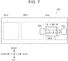
- FIG. 7 is a schematic view illustrating the fuel cell vehicle according to the second embodiment.
- FIG. 8 is a top view schematically illustrating a configuration of an essential part of the fuel cell vehicle according to the second embodiment.
- FIG. 9 is a side view schematically illustrating the configuration of the essential part of the fuel cell vehicle according to the second embodiment.
- FIG. 9 is a side view schematically illustrating the configuration of the essential part of the fuel cell vehicle illustrated in FIG. 8 .
- FIG. 9 is a side view schematically illustrating the configuration of the essential part of the fuel cell vehicle illustrated in FIG. 8 .
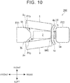
- FIG. 10 is a top view schematically illustrating an operation of the essential part in a case where the fuel cell vehicle according to the second embodiment has a collision.
- FIG. 11 is a side view schematically illustrating the operation of the essential part in a case where the fuel cell vehicle according to the second embodiment has a collision.
- FIG. 7 is a view of a fuel cell vehicle 502 when the fuel cell vehicle 502 is viewed from above.
- FIGS. 8 and 10 are views of a stack frame 200 when the stack frame 200 is viewed from above.
- FIGS. 9 and 11 are views of the stack frame 200 when the stack frame 200 is viewed from its left side.
- the stack frame 200, a fuel tank P21, and a vehicle component P22 are illustrated in a continuous line.
- the fuel cell vehicle 502 similarly to the fuel cell vehicle 501 illustrated in FIG. 1 , the fuel cell vehicle 502 includes the front-side compartment 501a, the vehicle cabin 501b, and the rear-side compartment 501c.
- the fuel cell vehicle 502 includes four wheels (not shown), for example, and the four wheels are provided at four corners of the fuel cell vehicle 502, respectively.
- the stack frame 200 is placed in the rear-side compartment 501c.
- a fuel cell stack 502d is provided in the stack frame 200. That is, the fuel cell stack 502d is placed on the upper side of the stack frame 200.
- the fuel tank P21 should be placed in front of the stack frame 200. More specifically, the fuel tank P21 is placed below the vehicle cabin 501b or in front of the rear-side compartment 501c. Note that the fuel tank P21 is placed such that, when the fuel cell vehicle 502 has a rear end collision, the fuel tank P21 moves rearward so that the fuel tank P21 is not damaged.
- the fuel tank P21 has the same configuration as the fuel tank P1.
- the vehicle component P22 is placed in the rear-side compartment 501c and placed behind the stack frame 200.
- the vehicle component P22 should be a component provided in the fuel cell vehicle and is, for example, a rear bumper reinforcement or the like.
- the vehicle component P22 should have a rigidity higher than the crash box 5.
- the stack frame 200 has the same configuration as the stack frame 100, but the stack frame 200 is placed in the same orientation in the right-left direction as the stack frame 100 but is reverse to the stack frame 100 in the front-rear direction. Therefore, the stack frame 200 has a configuration with reference signs different from those in the configuration of the stack frame 100 but has substantially the same configuration as the stack frame 100 except that the stack frame 200 is reverse to the stack frame 100 in the front-rear direction.
- the central member 2 includes a front-end portion 2b having the same configuration as the rear-end portion 2a illustrated in FIG. 3 .
- a rear cross member 24 has the same configuration as the front cross member 4, while the rear cross member 24 is reverse to the front cross member 4 in the front-rear direction.
- first joining portion W12 between the central member 2 and the right member 1 includes a rear-end portion W12c having the same configuration as the front-end portion W12a illustrated in FIG. 3 .
- second joining portion W23 between the central member 2 and the left member 3 includes a rear-end portion W23c having the same configuration as the front-end portion W23a illustrated in FIG. 3 .
- the rear-end portion W12c of the first joining portion W12 between the central member 2 and the right member 1 and the rear-end portion W23c of the second joining portion W23 between the central member 2 and the left member 3 overlap with the third joining portion W40 of the rear cross member 24 with rear edge portions of the central member 2, the right member 1, and the left member 3.
- the rear-end portions W12c, W23c overlap with the join line W3.
- the mechanical strength of the rear end portion W12c of the first joining portion W12 is lower than the mechanical strength of the central portion W12e of the first joining portion W12.
- the mechanical strength of the rear end portion W23c of the second joining portion W23 is lower than the mechanical strength of the central portion W23e of the second joining portion W23.
- the crash box 5 is placed behind the rear cross member 24.
- the crash box 5 is attached to a rear-end portion of the body portion 10 via the rear cross member 24.
- the stack frame 200 may have a configuration different from that of the stack frame 100 appropriately so that the stack frame 200 is fitted to a configuration of the rear-side compartment 501c and its surrounding configuration.
- each constituent of the fuel cell vehicle 502 when the stack frame 200 receives a large impact from the rear side due to a rear end collision or the like of the fuel cell vehicle 502.
- the stack frame 200 receives a large impact from the rear side. More specifically, the vehicle component P22 abuts with the distal end portion 5a of the crash box 5, so that the crash box 5 is sandwiched between the vehicle component P22 and the body portion 10 and deforms by compression. In the meantime, the fuel tank P21 moves rearward and makes contact with the right member 1 and the left member 3. Note that the inclined surfaces P1b of a rear-end portion of the fuel tank P21 should abut with the corners 1b, 3b, on the central member 2 side, of front ends of the right member 1 and the left member 3.
- the right member 1 and the left member 3 receive respective forces by the fuel tank P21 in respective directions to be distanced from the central member 2.
- the mechanical strength of a front-end portion W12d of the first joining portion W12 is lower than the mechanical strength of the central portion W12e of the first joining portion W12. Further, since the rear-end portion W12c of the first joining portion W12 overlaps with the join line W3, the mechanical strength of the rear-end portion W12c of the first joining portion W12 is higher than the mechanical strength of the front-end portion W12d. Accordingly, the front-end portion W12d easily becomes a starting point of breaking of the first joining portion W12.
- the right member 1 is disjoined from the central member 2, so that the front side of the right member 1 is separated from the central member 2.
- the mechanical strength of a front-end portion W23d of the second joining portion W23 is lower than the mechanical strength of the central portion of the second joining portion W23.
- the mechanical strength of the rear-end portion W23c of the second joining portion W23 is higher than the mechanical strength of the front-end portion W23d. Accordingly, the front-end portion W23d easily becomes a starting point of breaking of the second joining portion W23.
- the left member 3 is disjoined from the central member 2, so that the front side of the left member 3 is separated from the central member 2.
- the mechanical strengths of the right end portion W40a and the left end portion W40c of the third joining portion W40 are lower than the mechanical strength of the central portion W40b of the third joining portion W40. Accordingly, the right end portion W40a and the left end portion W40c easily become starting points of breaking of the third joining portion W40. Accordingly, while the central portion 4b of the rear cross member 24 is maintained to be joined to the central member 2, the right end portion 4a of the rear cross member 24 deforms to be separated from the right member 1, and the right end portion 4a is disjoined from the right member 1. Further, the left end portion 4c of the rear cross member 24 deforms to be separated from the left member 3, and the left end portion 4c is disjoined from the left member 3.
- the right end portion 4a and the left end portion 4c bend from the central portion 4b, so that the rear cross member 24 deforms into a generally C-shape.
- the right member 1 and the left member 3 easily deform so as to be separated from the fuel tank P21 and the central member 2.
- the fuel tank P21 further moves rearward and passes below the front-end portion 2b of the central member 2, and then, the fuel tank P21 moves to a region below the body portion 10.
- the right member 1 and the left member 3 deform to follow the movement of the fuel tank P21.
- the fuel tank P21 can be hardly damaged in comparison with a case where the right member 1 and the left member 3 are maintained to be joined to the central member 2. Accordingly, it is possible to restrain the breakage of the fuel tank P21 due to the stack frame 200 colliding with the fuel tank P21.
- the front-end portion 2b of the central member 2 in the present embodiment is placed behind the front-end portion 1c of the right member 1 and the front-end portion 3c of the left member 3.
- the stack frame 200 of the present embodiment is constituted by the central member 2, the right member 1, the left member 3, and the rear cross member 24.
- the fuel tank P21 of the present embodiment includes the front-end portion having the width L3 longer than the width L2 of the central member 2.
- the right member 1 and the left member 3 easily hit the fuel tank P21, so that the front side of the left member 3 and the front side of the right member 1 easily receive respective forces in respective directions to be separated from the central member 2.
- the left member 3 and the right member 1 are easily separated from the central member 2 and easily move to follow the movement of the fuel tank P21, thereby resulting in that the fuel tank P21 can be further hardly damaged.
- the fuel cell vehicle 502 of the present embodiment further includes the crash box 5 placed in front of the rear cross member 24. Further, as illustrated in FIG. 2 , the crash box 5 of the present embodiment is placed between the extension line W1b of the join line W1 between the central member 2 and the right member 1 and the extension line W2b of the join line W2 between the central member 2 and the left member 3.
- the central portion 4b of the rear cross member 24 is maintained to be joined to the central member 2
- the right end portion 4a of the rear cross member 24 and the left end portion 4c of the rear cross member 24 easily deform such that the right end portion 4a is separated from the right member 1 and the left end portion 4c is separated from the left member 3. Accordingly, the right member 1 and the left member 3 easily move to follow the movement of the fuel tank P21, thereby resulting in that the fuel tank P21 can be further hardly damaged.
- the mechanical strength of the first joining portion W12 between the central member 2 and the right member 1 and the mechanical strength of the second joining portion W23 between the central member 2 and the left member 3 in the present embodiment are lower than the mechanical strengths of the outer wall of the fuel tank P21, the right member 1, and the left member 3.
- the first joining portion W12 between the right member 1 and the central member 2 and the second joining portion W23 between the left member 3 and the central member 2 are easily broken in comparison with the outer wall of the fuel tank P21, the right member 1, and the left member 3. Accordingly, the right member 1 and the left member 3 easily move to follow the movement of the fuel tank P21 separated from the central member 2, thereby resulting in that the fuel tank P21 can be further hardly damaged.
Landscapes
- Engineering & Computer Science (AREA)
- Sustainable Development (AREA)
- Sustainable Energy (AREA)
- Life Sciences & Earth Sciences (AREA)
- Mechanical Engineering (AREA)
- Chemical & Material Sciences (AREA)
- Transportation (AREA)
- General Chemical & Material Sciences (AREA)
- Manufacturing & Machinery (AREA)
- Chemical Kinetics & Catalysis (AREA)
- Electrochemistry (AREA)
- Power Engineering (AREA)
- Combustion & Propulsion (AREA)
- General Engineering & Computer Science (AREA)
- Body Structure For Vehicles (AREA)
- Cooling, Air Intake And Gas Exhaust, And Fuel Tank Arrangements In Propulsion Units (AREA)
- Arrangement Or Mounting Of Propulsion Units For Vehicles (AREA)
- Electric Propulsion And Braking For Vehicles (AREA)
- Fuel Cell (AREA)
Abstract
Description
- The invention relates to a fuel cell vehicle, and particularly to a fuel cell vehicle including a stack frame that holds a fuel cell stack.
- Japanese Unexamined Patent Application Publication No.
2017-144859 JP 2017-144859 A - The present inventors came up with a fuel cell vehicle in which a fuel tank is placed below an occupant in order to secure a space inside the vehicle and extend a cruising range, and the present inventors examined the fuel cell vehicle.
- The present inventors found the following problems about the above technique. When the fuel cell vehicle receives an impact due to a front-end collision or the like, the fuel tank might collide with a stack frame, so that the fuel tank might be damaged. In a case where the fuel tank collides with a corner of the stack frame, the fuel tank might be damaged.
- The present invention provides a fuel cell vehicle that restrains breakage of a fuel tank provided in a fuel cell vehicle when the fuel cell vehicle receives an impact and the fuel tank collides with a stack frame.
- A first aspect of the invention relates to a fuel cell vehicle including a stack frame and a fuel tank. The stack frame is configured such that a fuel cell stack is provided thereon, and the stack frame is placed in front of a vehicle cabin. The stack frame includes a central member, a right member joined to a right edge portion of the central member, a left member joined to a left edge portion of the central member, and a front cross member. The front cross member is joined to front edge portions of the central member, the right member, and the left member. A front-end portion of a first joining portion between the central member and the right member and a front-end portion of a second joining portion between the central member and the left member overlap with a third joining portion of the front cross member with the front edge portions of the central member, the right member, and the left member. The fuel tank is placed behind the stack frame.
- In the first aspect, even when the fuel cell vehicle receives an impact and the fuel tank collides with the stack frame, the right member and the left member hit the fuel tank first, so that the rear side of the left member and the rear side of the right member receive respective forces in respective directions to be separated from the central member. The front-end portion of the first joining portion between the central member and the right member and the front-end portion of the second joining portion between the central member and the left member overlap with the third joining portion of the front cross member with the front edge portions of the central member, the right member, and the left member. A rear-end portion of the first joining portion between the central member and the right member and a rear-end portion of the second joining portion between the central member and the left member serve as starting points of breaking, and the left member and the right member are separated from the central member and move to follow the movement of the fuel tank. The fuel tank can be hardly damaged in comparison with a case where the fuel tank collides with a corner of the stack frame. This can accordingly restrain the breakage of the fuel tank.
- In the first aspect, a rear-end portion of the central member may be placed in front of a rear-end portion of the right member and a rear-end portion of the left member. Further, the fuel tank may include a front-end portion having a width longer than a distance between the right member and the left member.
- With the first configuration, the fuel tank easily hits the right member and the left member without hitting the central member, and the rear side of the left member and the rear side of the right member easily receive respective forces in respective directions to be separated from the central member. Accordingly, the left member and the right member are easily separated from the central member and easily move to follow the movement of the fuel tank, thereby resulting in that the fuel tank can be further hardly damaged.
- In the above aspect, the fuel cell vehicle may further include a crash box placed in front of the front cross member. The crash box may be placed between an extension line of a join line between the central member and the right member and an extension line of a join line between the central member and the left member.
- With the first configuration, while the center of the front cross member is maintained to be joined to the central member, the opposite ends of the front cross member deform to be separated from the right member and the left member. Accordingly, the left member and the right member easily move to follow the movement of the fuel tank, thereby resulting in that the fuel tank can be further hardly damaged.
- Further, the mechanical strength of the first joining portion between the central member and the right member and the mechanical strength of the second joining portion between the central member and the left member may be lower than the mechanical strengths of an outer wall of the fuel tank, the right member, and the left member. Further, the mechanical strengths of the right member and the left member may be higher than the mechanical strength of an outer wall of the fuel tank.
- With the first configuration, while the front cross member is maintained to be joined to the central member, the front cross member deforms to be disjoined from the right member and the left member. Accordingly, the left member and the right member easily move to follow the movement of the fuel tank separated from the central member, thereby resulting in that the fuel tank can be further hardly damaged.
- A second aspect of the invention relates to a fuel cell vehicle including a stack frame and a fuel tank. The stack frame is configured such that a fuel cell stack is provided thereon, and the stack frame is placed behind a vehicle cabin. The stack frame includes a central member, a right member joined to a right edge portion of the central member, a left member joined to a left edge portion of the central member, and a rear cross member. The rear cross member is joined to rear edge portions of the central member, the right member, and the left member. A rear-end portion of a first joining portion between the central member and the right member and a rear-end portion of a second joining portion between the central member and the left member overlap with a third joining portion of the rear cross member with the rear edge portions of the central member, the right member, and the left member. The fuel tank is placed in front of the stack frame.
- In the second aspect, even when the fuel cell vehicle receives an impact and the fuel tank collides with the stack frame, the right member and the left member hit the fuel tank first, so that the front side of the left member and the front side of the right member receive respective forces in respective directions to be separated from the central member. The rear-end portion of the first joining portion between the central member and the right member and the rear-end portion of the second joining portion between the central member and the left member overlap with the third joining portion of the rear cross member with the rear edge portions of the central member, the right member, and the left member. A front-end portion of the first joining portion between the central member and the right member and a front-end portion of the second joining portion between the central member and the left member serve as starting points of breaking, and the left member and the right member are separated from the central member and move to follow the movement of the fuel tank. The fuel tank can be hardly damaged in comparison with a case where the fuel tank collides with a corner of the stack frame. This makes it possible to restrain a breakage of the fuel tank.
- With each aspect of the invention, it is possible to restrain the breakage of the fuel tank due to the stack frame colliding with the fuel tank when the fuel cell vehicle receives an impact.
- Features, advantages, and technical and industrial significance of exemplary embodiments of the invention will be described below with reference to the accompanying drawings, in which like numerals denote like elements, and wherein:
-
FIG. 1 is a schematic view illustrating a fuel cell vehicle according to a first embodiment of the invention; -
FIG. 2 is a top view illustrating one concrete example of a configuration of an essential part of the fuel cell vehicle according to the first embodiment; -
FIG. 3 is a top view schematically illustrating the configuration of the essential part of the fuel cell vehicle according to the first embodiment; -
FIG. 4 is a side view schematically illustrating the configuration of the essential part of the fuel cell vehicle according to the first embodiment; -
FIG. 5 is a top view schematically illustrating an operation of the essential part in a case where the fuel cell vehicle according to the first embodiment has a collision; -
FIG. 6 is a side view schematically illustrating the operation of the essential part in a case where the fuel cell vehicle according to the first embodiment has a collision; -
FIG. 7 is a schematic view illustrating a fuel cell vehicle according to a second embodiment of the invention; -
FIG. 8 is a top view schematically illustrating a configuration of an essential part of the fuel cell vehicle according to the second embodiment; -
FIG. 9 is a side view schematically illustrating the configuration of the essential part of the fuel cell vehicle according to the second embodiment; -
FIG. 10 is a top view schematically illustrating an operation of the essential part in a case where the fuel cell vehicle according to the second embodiment has a collision; and -
FIG. 11 is a side view schematically illustrating the operation of the essential part in a case where the fuel cell vehicle according to the second embodiment has a collision. - Concrete embodiments to which the invention is applied will be described in detail with reference to the drawings. However, the invention is not limited to the following embodiments. Further, the following description and drawings are simplified appropriately for clarification of the description.
- Initially described is a fuel cell vehicle according to a first embodiment of the invention with reference to
FIGS. 1 to 6 .FIG. 1 is a schematic view illustrating a fuel cell vehicle according to the first embodiment.FIG. 2 is a top view illustrating one concrete example of a configuration of an essential part of the fuel cell vehicle according to the first embodiment.FIG. 3 is a top view schematically illustrating the configuration of the essential part of the fuel cell vehicle according to the first embodiment.FIG. 4 is a side view schematically illustrating the configuration of the essential part of the fuel cell vehicle according to the first embodiment.FIG. 4 is a side view schematically illustrating the configuration of the essential part of the fuel cell vehicle illustrated inFIG. 3 .FIG. 5 is a top view schematically illustrating an operation of the essential part in a case where the fuel cell vehicle according to the first embodiment has a collision.FIG. 6 is a side view schematically illustrating the operation of the essential part in a case where the fuel cell vehicle according to the first embodiment has a collision. - Note that, naturally, the three-dimensional orthogonal coordinate in
FIG. 1 and other drawings indicates the up-down direction, the right-left direction, and the front-rear direction and is illustrated for convenience to describe a positional relationship between constituents. Generally, the upper side of the coordinate is the upper side in the vertical direction, and the plane extending in the front-rear direction and in the right-left direction is a horizontal plane. This is common between the drawings.FIG. 1 is a view of afuel cell vehicle 501 when thefuel cell vehicle 501 is viewed from above.FIGS. 2 ,3 , and5 are views of astack frame 100 when thestack frame 100 is viewed from above.FIGS. 4 and6 are views of thestack frame 100 when thestack frame 100 is viewed from its left side. InFIG. 1 , for easy understanding, thestack frame 100, a fuel tank P1, and a vehicle component P2 are illustrated in a continuous line. - As illustrated in
FIG. 1 , thefuel cell vehicle 501 includes a front-side compartment 501a, avehicle cabin 501b, and a rear-side compartment 501c. The front-side compartment 501a is placed in front of thevehicle cabin 501b, and the rear-side compartment 501c is placed behind thevehicle cabin 501b. Thevehicle cabin 501b is a space where an occupant is seated. Thefuel cell vehicle 501 includes four wheels (not shown), for example, and the four wheels are provided at four corners of thefuel cell vehicle 501, respectively. - The
stack frame 100 is placed in the front-side compartment 501a. Afuel cell stack 501d is provided in thestack frame 100. That is, thefuel cell stack 501d is placed on the upper side of thestack frame 100. - The fuel tank P1 should be placed behind the
stack frame 100. More specifically, the fuel tank P1 is placed below thevehicle cabin 501b or behind the front-side compartment 501a. Note that, when thefuel cell vehicle 501 has a front-end collision, the fuel tank P1 moves forward so that the fuel tank P1 is not damaged. Hydrogen is stored in the fuel tank P1, for example. - The vehicle component P2 is placed in the front-
side compartment 501a and placed in front of thestack frame 100. The vehicle component P2 should be a component provided in the fuel cell vehicle and is, for example, a fan motor of a radiator, a front bumper reinforcement, or the like. The vehicle component P2 should have a rigidity higher than that of acrash box 5. Various types of vehicle components, e.g., a front side member, are placed near the vehicle component P2, for example. - As illustrated in
FIGS. 2 and3 , thestack frame 100 includes abody portion 10 and thecrash box 5. Thestack frame 100 may include only thebody portion 10. - The
body portion 10 includes aright member 1, acentral member 2, aleft member 3, and afront cross member 4. Thebody portion 10 may include only theright member 1, thecentral member 2, theleft member 3, and thefront cross member 4. - The
right member 1, thecentral member 2, and theleft member 3 are placed in this order from the right side to the left side. Theright member 1 and theleft member 3 sandwich thecentral member 2 therebetween. A distance between theright member 1 and theleft member 3 is smaller than a width L3 of the fuel tank P1. The distance between theright member 1 and theleft member 3 is the same length as a width L2 of thecentral member 2. A front-end portion of the fuel tank P1 should have inclined surfaces P1b inclined in the front-rear direction. A rear-end portion 2a of thecentral member 2 is placed in front of a rear-end portion 1a of theright member 1 and a rear-end portion 3a of theleft member 3. As illustrated inFIG. 4 , the rear-end portion 2a of thecentral member 2 should be placed above an upper end P1a of the fuel tank P1. Theright member 1, thecentral member 2, and theleft member 3 should be plate-shaped bodies, and more specifically, extruded members made of aluminum alloy. - The
right member 1 and thecentral member 2 are joined to each other along a join line W1 by friction stir welding (FSW), so that a first joining portion W12 between theright member 1 and thecentral member 2 is formed. Thecentral member 2 and theleft member 3 are joined to each other along a join line W2 by FSW, so that a second joining portion W23 between thecentral member 2 and theleft member 3 is formed. Examples of the join lines W1, W2 illustrated inFIG. 1 are adjacent to each other and extend in parallel to each other. Accordingly, theright member 1 is joined to a right edge portion of thecentral member 2, and theleft member 3 is joined to a left edge portion of thecentral member 2. - The
front cross member 4 should be a bar-shaped body extending in the right-left direction. Thefront cross member 4 is joined to theright member 1, thecentral member 2, and theleft member 3 along a join line W3 by FSW. Thefront cross member 4 is joined to front edge portions of thecentral member 2, theright member 1, and theleft member 3, so that a third joining portion W40 is formed. Thefront cross member 4 includes aright end portion 4a, acentral portion 4b, and aleft end portion 4c, such that theright end portion 4a, thecentral portion 4b, and theleft end portion 4c extend continuously in this order from the right to the left. Theright end portion 4a is joined to theright member 1, thecentral portion 4b is joined to thecentral member 2, and theleft end portion 4c is joined to theleft member 3. - A front-end portion W12a of the first joining portion W12 between the
central member 2 and theright member 1 and a front-end portion W23a of the second joining portion W23 between thecentral member 2 and theleft member 3 overlap with the third joining portion W40 of thefront cross member 4 with the front edge portions of thecentral member 2, theright member 1, and theleft member 3. In other words, the front-end portions W12a, W23a overlap with the join line W3. - The mechanical strength of a rear-end portion W12b of the first joining portion W12 is lower than the mechanical strength of a central portion W12e of the first joining portion W12. Similarly, the mechanical strength of a rear-end portion W23b of the second joining portion W23 is lower than the mechanical strength of a central portion W23e of the second joining portion W23. Further, similarly, the mechanical strengths of a right end portion W40a and a left end portion W40c of the third joining portion W40 are lower than the mechanical strength of a central portion W40b of the third joining portion W40.
- The mechanical strength of the first joining portion W12 between the
right member 1 and thecentral member 2 and the mechanical strength of the second joining portion W23 between thecentral member 2 and theleft member 3 should be lower than the mechanical strength of an outer wall of the fuel tank P1. Further, the mechanical strengths of theright member 1 and theleft member 3 should be higher than the mechanical strength of the outer wall of the fuel tank P1. - Note that, as described above, FSW is used to join the
right member 1, thecentral member 2, theleft member 3, and thefront cross member 4, but other various types of joining methods can be used. The other various types of joining methods include welding methods such as laser beam welding and arc-welding, for example. - Further, also on the bottom side of the
body portion 10, theright member 1, thecentral member 2, theleft member 3, and thefront cross member 4 should be joined along join lines similar to the join lines W1, W2, W3, so that joining portions similar to the first joining portion W12, the second joining portion W23 and the third joining portion W40 should be formed. When thestack frame 100 is viewed from above, the joining portions thus formed overlap with the first joining portion W12, the second joining portion W23 and the third joining portion W40. - The
crash box 5 is placed in front of thefront cross member 4. Thecrash box 5 is attached to a front-end portion of thebody portion 10 via thefront cross member 4. In comparison with thebody portion 10, thecrash box 5 easily deforms when thecrash box 5 receives an impact, and thus, thecrash box 5 absorbs impact energy. Thecrash box 5 is a tubular body having a square section, for example. As illustrated inFIG. 2 , thecrash box 5 is placed between an extension line W1b of the join line W1 between thecentral member 2 and theright member 1 and an extension line W2b of the join line W2 between thecentral member 2 and theleft member 3. That is, a width L1 of thecrash box 5 is less than a distance between the extension line W1b and the extension line W2b. In other words, the width L1 is smaller than the width L2 of thecentral member 2. - With reference to
FIGS. 3 to 6 , the following describes an operation of each constituent of thefuel cell vehicle 501 when thestack frame 100 receives a large impact from the front side due to a front end collision or the like of thefuel cell vehicle 501. - As illustrated in
FIGS. 3 and4 , when thefuel cell vehicle 501 has a front-end collision, thestack frame 100 receives a large impact from the front side. More specifically, the vehicle component P2 abuts with adistal end portion 5a of thecrash box 5, so that thecrash box 5 is sandwiched between the vehicle component P2 and thebody portion 10 and deforms by compression. In the meantime, the fuel tank P1 moves forward and makes contact with theright member 1 and theleft member 3. Note that the inclined surfaces P1b of the front-end portion of the fuel tank P1 should abut withcorners central member 2 side, of rear ends of theright member 1 and theleft member 3. - As illustrated in
FIG. 5 , theright member 1 and theleft member 3 receive respective forces by the fuel tank P1 in respective directions to be separated from thecentral member 2. - As described above, the mechanical strength of the rear-end portion W12b of the first joining portion W12 is lower than the mechanical strength of the central portion W12e of the first joining portion W12. Further, since the front-end portion W12a of the first joining portion W12 overlaps with the join line W3, the mechanical strength of the front-end portion W12a of the first joining portion W12 is higher than the mechanical strength of the rear-end portion W12b. Accordingly, the rear-end portion W12b easily becomes a starting point of breaking of the first joining portion W12. The
right member 1 is disjoined from thecentral member 2, so that the rear side of theright member 1 is separated from thecentral member 2. - Similarly, the mechanical strength of the rear-end portion W23b of the second joining portion W23 is lower than the mechanical strength of the central portion W23e of the second joining portion W23. Further, since the front-end portion W23a of the second joining portion W23 overlaps with the join line W3, the mechanical strength of the front-end portion W23a of the second joining portion W23 is higher than the mechanical strength of the rear-end portion W23b. Accordingly, the rear-end portion W23b easily becomes a starting point of breaking of the second joining portion W23. The
left member 3 is disjoined from thecentral member 2, so that the rear side of theleft member 3 is separated from thecentral member 2. - Similarly, the mechanical strengths of the right end portion W40a and the left end portion W40c of the third joining portion W40 are lower than the mechanical strength of the central portion W40b of the third joining portion W40. Accordingly, the right end portion W40a and the left end portion W40c easily become starting points of breaking of the joining portion W40. On this account, while the
central portion 4b of thefront cross member 4 is maintained to be joined to thecentral member 2, theright end portion 4a of thefront cross member 4 deforms to be separated from theright member 1, so that theright end portion 4a is disjoined from theright member 1. Further, theleft end portion 4c of thefront cross member 4 deforms to be separated from theleft member 3, so that theleft end portion 4c is disjoined from theleft member 3. In other words, theright end portion 4a and theleft end portion 4c bend from thecentral portion 4b, so that thefront cross member 4 deforms into a generally C-shape. Hereby, theright member 1 and theleft member 3 easily deform so as to be separated from the fuel tank P1 and thecentral member 2. - As illustrated in
FIG. 6 , the fuel tank P1 further moves forward and passes below the rear-end portion 2a of thecentral member 2, so that the fuel tank P1 moves to a region below thebody portion 10. - As described above, the
right member 1 and theleft member 3 deform to follow the movement of the fuel tank P1. On this account, in such a case, even if the fuel tank P1 collides with thestack frame 100, the fuel tank P1 can be hardly damaged in comparison with a case where theright member 1 and theleft member 3 are maintained to be joined to thecentral member 2. Accordingly, it is possible to restrain the breakage of the fuel tank P1 due to thestack frame 100 colliding with the fuel tank P1. - Further, the rear-
end portion 2a of thecentral member 2 in the present embodiment is placed in front of the rear-end portion 1a of theright member 1 and the rear-end portion 3a of theleft member 3. Further, thestack frame 100 of the present embodiment is constituted by thecentral member 2, theright member 1, theleft member 3, and thefront cross member 4. Further, the fuel tank P1 of the present embodiment includes the front-end portion having the width L3 longer than the distance between theright member 1 and theleft member 3. Hereby, theright member 1 and theleft member 3 easily hit the fuel tank P1, so that the rear side of theleft member 3 and the rear side of theright member 1 easily receive respective forces in respective directions to be separated from thecentral member 2. Accordingly, theleft member 3 and theright member 1 are easily separated from thecentral member 2 and easily move to follow the movement of the fuel tank P1, thereby resulting in that the fuel tank P1 can be further hardly damaged. - Further, the
fuel cell vehicle 501 of the present embodiment further includes thecrash box 5 placed in front of thefront cross member 4. Further, as illustrated inFIG. 2 , thecrash box 5 of the present embodiment is placed between the extension line W1b of the join line W1 between thecentral member 2 and theright member 1 and the extension line W2b of the join line W2 between thecentral member 2 and theleft member 3. Hereby, while thecentral portion 4b of thefront cross member 4 is maintained to be joined to thecentral member 2, theright end portion 4a and theleft end portion 4c easily deform such that theright end portion 4a is separated from theright member 1 and theleft end portion 4c is separated from theleft member 3. On this account, theright member 1 and theleft member 3 easily move to follow the movement of the fuel tank P1, thereby resulting in that the fuel tank P1 can be further hardly damaged. - Further, the mechanical strength of the first joining portion W12 between the
central member 2 and theright member 1 and the mechanical strength of the second joining portion W23 between thecentral member 2 and theleft member 3 in the present embodiment are lower than the mechanical strengths of the outer wall of the fuel tank P1, theright member 1, and theleft member 3. On this account, the first joining portion W12 between theright member 1 and thecentral member 2 and the second joining portion W23 between theleft member 3 and thecentral member 2 are easily broken in comparison with the outer wall of the fuel tank P1, theright member 1, and theleft member 3. On this account, theright member 1 and theleft member 3 are easily separated from thecentral member 2 and easily move to follow the movement of the fuel tank P1, thereby resulting in that the fuel tank P1 can be further hardly damaged. - Next will be described a fuel cell vehicle according to a second embodiment of the invention with reference to
FIGS. 7 to 11 . The fuel cell vehicle of the second embodiment has a configuration generally the same as the fuel cell vehicle of the first embodiment except for the position of the stack frame.FIG. 7 is a schematic view illustrating the fuel cell vehicle according to the second embodiment.FIG. 8 is a top view schematically illustrating a configuration of an essential part of the fuel cell vehicle according to the second embodiment.FIG. 9 is a side view schematically illustrating the configuration of the essential part of the fuel cell vehicle according to the second embodiment.FIG. 9 is a side view schematically illustrating the configuration of the essential part of the fuel cell vehicle illustrated inFIG. 8 .FIG. 10 is a top view schematically illustrating an operation of the essential part in a case where the fuel cell vehicle according to the second embodiment has a collision.FIG. 11 is a side view schematically illustrating the operation of the essential part in a case where the fuel cell vehicle according to the second embodiment has a collision. -
FIG. 7 is a view of afuel cell vehicle 502 when thefuel cell vehicle 502 is viewed from above.FIGS. 8 and10 are views of astack frame 200 when thestack frame 200 is viewed from above.FIGS. 9 and11 are views of thestack frame 200 when thestack frame 200 is viewed from its left side. InFIG. 7 , for easy understanding, thestack frame 200, a fuel tank P21, and a vehicle component P22 are illustrated in a continuous line. - As illustrated in
FIG. 7 , similarly to thefuel cell vehicle 501 illustrated inFIG. 1 , thefuel cell vehicle 502 includes the front-side compartment 501a, thevehicle cabin 501b, and the rear-side compartment 501c. Thefuel cell vehicle 502 includes four wheels (not shown), for example, and the four wheels are provided at four corners of thefuel cell vehicle 502, respectively. - The
stack frame 200 is placed in the rear-side compartment 501c. Afuel cell stack 502d is provided in thestack frame 200. That is, thefuel cell stack 502d is placed on the upper side of thestack frame 200. - The fuel tank P21 should be placed in front of the
stack frame 200. More specifically, the fuel tank P21 is placed below thevehicle cabin 501b or in front of the rear-side compartment 501c. Note that the fuel tank P21 is placed such that, when thefuel cell vehicle 502 has a rear end collision, the fuel tank P21 moves rearward so that the fuel tank P21 is not damaged. The fuel tank P21 has the same configuration as the fuel tank P1. - The vehicle component P22 is placed in the rear-
side compartment 501c and placed behind thestack frame 200. The vehicle component P22 should be a component provided in the fuel cell vehicle and is, for example, a rear bumper reinforcement or the like. The vehicle component P22 should have a rigidity higher than thecrash box 5. - As illustrated in
FIG. 8 , thestack frame 200 has the same configuration as thestack frame 100, but thestack frame 200 is placed in the same orientation in the right-left direction as thestack frame 100 but is reverse to thestack frame 100 in the front-rear direction. Therefore, thestack frame 200 has a configuration with reference signs different from those in the configuration of thestack frame 100 but has substantially the same configuration as thestack frame 100 except that thestack frame 200 is reverse to thestack frame 100 in the front-rear direction. For example, thecentral member 2 includes a front-end portion 2b having the same configuration as the rear-end portion 2a illustrated inFIG. 3 . Arear cross member 24 has the same configuration as thefront cross member 4, while therear cross member 24 is reverse to thefront cross member 4 in the front-rear direction. Further, the first joining portion W12 between thecentral member 2 and theright member 1 includes a rear-end portion W12c having the same configuration as the front-end portion W12a illustrated inFIG. 3 . Further, the second joining portion W23 between thecentral member 2 and theleft member 3 includes a rear-end portion W23c having the same configuration as the front-end portion W23a illustrated inFIG. 3 . - The rear-end portion W12c of the first joining portion W12 between the
central member 2 and theright member 1 and the rear-end portion W23c of the second joining portion W23 between thecentral member 2 and theleft member 3 overlap with the third joining portion W40 of therear cross member 24 with rear edge portions of thecentral member 2, theright member 1, and theleft member 3. In other words, the rear-end portions W12c, W23c overlap with the join line W3. - The mechanical strength of the rear end portion W12c of the first joining portion W12 is lower than the mechanical strength of the central portion W12e of the first joining portion W12. Similarly, the mechanical strength of the rear end portion W23c of the second joining portion W23 is lower than the mechanical strength of the central portion W23e of the second joining portion W23.
- The
crash box 5 is placed behind therear cross member 24. Thecrash box 5 is attached to a rear-end portion of thebody portion 10 via therear cross member 24. - Note that, in order that the
stack frame 200 is placed in the rear-side compartment 501c, thestack frame 200 may have a configuration different from that of thestack frame 100 appropriately so that thestack frame 200 is fitted to a configuration of the rear-side compartment 501c and its surrounding configuration. - With reference to
FIGS. 8 to 11 , the following describes an operation of each constituent of thefuel cell vehicle 502 when thestack frame 200 receives a large impact from the rear side due to a rear end collision or the like of thefuel cell vehicle 502. - As illustrated in
FIGS. 8 and9 , when thefuel cell vehicle 502 has a rear end collision, for example, thestack frame 200 receives a large impact from the rear side. More specifically, the vehicle component P22 abuts with thedistal end portion 5a of thecrash box 5, so that thecrash box 5 is sandwiched between the vehicle component P22 and thebody portion 10 and deforms by compression. In the meantime, the fuel tank P21 moves rearward and makes contact with theright member 1 and theleft member 3. Note that the inclined surfaces P1b of a rear-end portion of the fuel tank P21 should abut with thecorners central member 2 side, of front ends of theright member 1 and theleft member 3. - As illustrated in
FIG. 10 , theright member 1 and theleft member 3 receive respective forces by the fuel tank P21 in respective directions to be distanced from thecentral member 2. - As described above, the mechanical strength of a front-end portion W12d of the first joining portion W12 is lower than the mechanical strength of the central portion W12e of the first joining portion W12. Further, since the rear-end portion W12c of the first joining portion W12 overlaps with the join line W3, the mechanical strength of the rear-end portion W12c of the first joining portion W12 is higher than the mechanical strength of the front-end portion W12d. Accordingly, the front-end portion W12d easily becomes a starting point of breaking of the first joining portion W12. The
right member 1 is disjoined from thecentral member 2, so that the front side of theright member 1 is separated from thecentral member 2. - Similarly, the mechanical strength of a front-end portion W23d of the second joining portion W23 is lower than the mechanical strength of the central portion of the second joining portion W23. Further, since the rear-end portion W23c of the second joining portion W23 overlaps with the join line W3, the mechanical strength of the rear-end portion W23c of the second joining portion W23 is higher than the mechanical strength of the front-end portion W23d. Accordingly, the front-end portion W23d easily becomes a starting point of breaking of the second joining portion W23. The
left member 3 is disjoined from thecentral member 2, so that the front side of theleft member 3 is separated from thecentral member 2. - Similarly, the mechanical strengths of the right end portion W40a and the left end portion W40c of the third joining portion W40 are lower than the mechanical strength of the central portion W40b of the third joining portion W40. Accordingly, the right end portion W40a and the left end portion W40c easily become starting points of breaking of the third joining portion W40. Accordingly, while the
central portion 4b of therear cross member 24 is maintained to be joined to thecentral member 2, theright end portion 4a of therear cross member 24 deforms to be separated from theright member 1, and theright end portion 4a is disjoined from theright member 1. Further, theleft end portion 4c of therear cross member 24 deforms to be separated from theleft member 3, and theleft end portion 4c is disjoined from theleft member 3. In other words, theright end portion 4a and theleft end portion 4c bend from thecentral portion 4b, so that therear cross member 24 deforms into a generally C-shape. Hereby, theright member 1 and theleft member 3 easily deform so as to be separated from the fuel tank P21 and thecentral member 2. - As illustrated in
FIG. 11 , the fuel tank P21 further moves rearward and passes below the front-end portion 2b of thecentral member 2, and then, the fuel tank P21 moves to a region below thebody portion 10. - Thus, the
right member 1 and theleft member 3 deform to follow the movement of the fuel tank P21. On this account, in such a case, even if the fuel tank P21 collides with thestack frame 200, the fuel tank P21 can be hardly damaged in comparison with a case where theright member 1 and theleft member 3 are maintained to be joined to thecentral member 2. Accordingly, it is possible to restrain the breakage of the fuel tank P21 due to thestack frame 200 colliding with the fuel tank P21. - Further, the front-
end portion 2b of thecentral member 2 in the present embodiment is placed behind the front-end portion 1c of theright member 1 and the front-end portion 3c of theleft member 3. Further, thestack frame 200 of the present embodiment is constituted by thecentral member 2, theright member 1, theleft member 3, and therear cross member 24. Further, the fuel tank P21 of the present embodiment includes the front-end portion having the width L3 longer than the width L2 of thecentral member 2. Hereby, theright member 1 and theleft member 3 easily hit the fuel tank P21, so that the front side of theleft member 3 and the front side of theright member 1 easily receive respective forces in respective directions to be separated from thecentral member 2. Accordingly, theleft member 3 and theright member 1 are easily separated from thecentral member 2 and easily move to follow the movement of the fuel tank P21, thereby resulting in that the fuel tank P21 can be further hardly damaged. - Further, the
fuel cell vehicle 502 of the present embodiment further includes thecrash box 5 placed in front of therear cross member 24. Further, as illustrated inFIG. 2 , thecrash box 5 of the present embodiment is placed between the extension line W1b of the join line W1 between thecentral member 2 and theright member 1 and the extension line W2b of the join line W2 between thecentral member 2 and theleft member 3. Hereby, while thecentral portion 4b of therear cross member 24 is maintained to be joined to thecentral member 2, theright end portion 4a of therear cross member 24 and theleft end portion 4c of therear cross member 24 easily deform such that theright end portion 4a is separated from theright member 1 and theleft end portion 4c is separated from theleft member 3. Accordingly, theright member 1 and theleft member 3 easily move to follow the movement of the fuel tank P21, thereby resulting in that the fuel tank P21 can be further hardly damaged. - Further, the mechanical strength of the first joining portion W12 between the
central member 2 and theright member 1 and the mechanical strength of the second joining portion W23 between thecentral member 2 and theleft member 3 in the present embodiment are lower than the mechanical strengths of the outer wall of the fuel tank P21, theright member 1, and theleft member 3. On this account, the first joining portion W12 between theright member 1 and thecentral member 2 and the second joining portion W23 between theleft member 3 and thecentral member 2 are easily broken in comparison with the outer wall of the fuel tank P21, theright member 1, and theleft member 3. Accordingly, theright member 1 and theleft member 3 easily move to follow the movement of the fuel tank P21 separated from thecentral member 2, thereby resulting in that the fuel tank P21 can be further hardly damaged. - Note that the invention is not limited to the above embodiments, and various modifications can be made appropriately within a range that does not deviate from the gist of the invention.
Claims (7)
- A fuel cell vehicle (501) comprising:a stack frame (100) on which a fuel cell stack (501d) is provided, the stack frame (100) being placed in front of a vehicle cabin,the stack frame (100) including a central member (2), a right member (1) joined to a right edge portion of the central member (2), a left member (3) joined to a left edge portion of the central member (2), and a front cross member (4),the front cross member (4) being joined to front edge portions of the central member (2), the right member (1), and the left member (3),a front-end portion (W12a) of a first joining portion (W12) between the central member (2) and the right member (1) and a front-end portion (W23a) of a second joining portion (W23) between the central member (2) and the left member (3) being overlapping with a third joining portion (W40) of the front cross member (4) with the front edge portions of the central member (2), the right member (1), and the left member (3); anda fuel tank (PI) placed behind the stack frame (100).
- The fuel cell vehicle (501) according to claim 1, wherein a rear-end portion of the central member (2) is placed in front of a rear-end portion of the right member (1) and a rear-end portion of the left member (3).
- The fuel cell vehicle (501) according to claim 1 or 2, wherein the fuel tank (PI) includes a front-end portion having a width longer than a distance between the right member (1) and the left member (3).
- The fuel cell vehicle (501) according to any one of claims 1 to 3, further comprising a crash box (5) placed in front of the front cross member (4), the crash box (5) being placed between an extension line of a join line (W1) between the central member (2) and the right member (1) and an extension line of a join line (W2) between the central member (2) and the left member (3).
- The fuel cell vehicle (501) according to any one of claims 1 to 4, wherein a mechanical strength of the first joining portion (W12) between the central member (2) and the right member (1) and a mechanical strength of the second joining portion (W23) between the central member (2) and the left member (3) are lower than mechanical strengths of an outer wall of the fuel tank (P1), the right member (1), and the left member (3).
- The fuel cell vehicle (501) according to any one of claims 1 to 5, wherein mechanical strengths of the right member (1) and the left member (3) are higher than a mechanical strength of an outer wall of the fuel tank (P1).
- A fuel cell vehicle (502) comprising:a stack frame (200) on which a fuel cell stack (502d) is provided, the stack frame (200) being placed behind a vehicle cabin,the stack frame (200) including a central member (2), a right member (1) joined to a right edge portion of the central member (2), a left member (3) joined to a left edge portion of the central member (2), and a rear cross member (24),the rear cross member (24) being joined to rear edge portions of the central member (2), the right member (1), and the left member (3),a rear-end portion (W12c) of a first joining portion (W12) between the central member (2) and the right member (1) and a rear-end portion (W23c) of a second joining portion (W23) between the central member (2) and the left member (3) being overlapping with a third joining portion (W40) of the rear cross member (24) with the rear edge portions of the central member (2), the right member (1), and the left member (3); anda fuel tank (P21) placed in front of the stack frame (200).
Applications Claiming Priority (1)
| Application Number | Priority Date | Filing Date | Title |
|---|---|---|---|
| JP2019015107A JP7115341B2 (en) | 2019-01-31 | 2019-01-31 | fuel cell vehicle |
Publications (3)
| Publication Number | Publication Date |
|---|---|
| EP3693202A2 true EP3693202A2 (en) | 2020-08-12 |
| EP3693202A3 EP3693202A3 (en) | 2020-09-16 |
| EP3693202B1 EP3693202B1 (en) | 2021-09-01 |
Family
ID=69167759
Family Applications (1)
| Application Number | Title | Priority Date | Filing Date |
|---|---|---|---|
| EP20151794.3A Active EP3693202B1 (en) | 2019-01-31 | 2020-01-14 | Fuel cell vehicle |
Country Status (4)
| Country | Link |
|---|---|
| US (1) | US11398636B2 (en) |
| EP (1) | EP3693202B1 (en) |
| JP (1) | JP7115341B2 (en) |
| CN (1) | CN111497646A (en) |
Citations (1)
| Publication number | Priority date | Publication date | Assignee | Title |
|---|---|---|---|---|
| JP2017144859A (en) | 2016-02-17 | 2017-08-24 | トヨタ自動車株式会社 | Fuel cell vehicle |
Family Cites Families (12)
| Publication number | Priority date | Publication date | Assignee | Title |
|---|---|---|---|---|
| US7303211B2 (en) | 2001-08-23 | 2007-12-04 | Gm Global Technology Operations, Inc. | Fuel cell vehicle architecture |
| JP4825583B2 (en) * | 2005-06-28 | 2011-11-30 | 本田技研工業株式会社 | Body structure |
| JP4977067B2 (en) | 2007-08-21 | 2012-07-18 | 本田技研工業株式会社 | Rear body structure of automobile |
| JP2009137443A (en) | 2007-12-06 | 2009-06-25 | Toyota Motor Corp | Electric vehicle |
| JP4508260B2 (en) | 2008-03-21 | 2010-07-21 | 三菱自動車工業株式会社 | Electric vehicle power plant mounting structure |
| DE102008029178A1 (en) | 2008-06-19 | 2009-12-24 | Daimler Ag | Fuel cell system for use as mobile energy generator for driving vehicle, has counter-compensation mechanism supported at auxiliary component and/or fluid line on one side and at base on another side for counter-compensation |
| EP2439128B1 (en) | 2009-06-05 | 2016-11-30 | Toyota Jidosha Kabushiki Kaisha | Vehicle |
| JP5652719B2 (en) * | 2011-05-02 | 2015-01-14 | スズキ株式会社 | Fuel cell vehicle |
| JP5831597B1 (en) * | 2014-06-06 | 2015-12-09 | トヨタ自動車株式会社 | Electric vehicle |
| JP6260797B2 (en) | 2015-10-13 | 2018-01-17 | トヨタ自動車株式会社 | Fuel cell vehicle |
| JP6622180B2 (en) | 2016-12-19 | 2019-12-18 | トヨタ自動車株式会社 | Fuel cell vehicle |
| JP6836153B2 (en) | 2017-01-26 | 2021-02-24 | アイシン精機株式会社 | Friction stir welding method |
-
2019
- 2019-01-31 JP JP2019015107A patent/JP7115341B2/en active Active
-
2020
- 2020-01-10 US US16/739,385 patent/US11398636B2/en active Active
- 2020-01-14 EP EP20151794.3A patent/EP3693202B1/en active Active
- 2020-01-22 CN CN202010073910.8A patent/CN111497646A/en active Pending
Patent Citations (1)
| Publication number | Priority date | Publication date | Assignee | Title |
|---|---|---|---|---|
| JP2017144859A (en) | 2016-02-17 | 2017-08-24 | トヨタ自動車株式会社 | Fuel cell vehicle |
Also Published As
| Publication number | Publication date |
|---|---|
| CN111497646A (en) | 2020-08-07 |
| EP3693202B1 (en) | 2021-09-01 |
| JP2020121654A (en) | 2020-08-13 |
| EP3693202A3 (en) | 2020-09-16 |
| JP7115341B2 (en) | 2022-08-09 |
| US11398636B2 (en) | 2022-07-26 |
| US20200251758A1 (en) | 2020-08-06 |
Similar Documents
| Publication | Publication Date | Title |
|---|---|---|
| US9580110B2 (en) | Vehicle body skeleton structure | |
| US8720985B2 (en) | Side body structure for vehicle | |
| JP6369550B2 (en) | Automotive parts | |
| CN109249882B (en) | body structure | |
| US12434649B2 (en) | Front vehicle-body structure | |
| CN111746648B (en) | Subframe for vehicle | |
| JP2019093942A (en) | Front part vehicle body structure of vehicle | |
| JP2002120765A (en) | Body structure | |
| CN108495777A (en) | Front part structure of vehicle | |
| WO2019035185A1 (en) | Bumper beam and vehicle | |
| TW201623053A (en) | Impact absorption member | |
| US10647276B2 (en) | Vehicle body structure | |
| JP7172889B2 (en) | vehicle | |
| US9868467B2 (en) | Vehicle body front portion structure | |
| CN109591892B (en) | Upper arch structure of vehicle body side portion | |
| CN110884567B (en) | Front body structure of vehicle | |
| EP3693202B1 (en) | Fuel cell vehicle | |
| US11286004B2 (en) | Lateral push element | |
| CN111674468B (en) | Vehicle front structure | |
| US10336374B2 (en) | Vehicle rear portion structure | |
| JP6704870B2 (en) | Bumper reinforcement | |
| JP2021066268A (en) | Side sill structure of automobile | |
| JP2018058525A (en) | Load transmission system for vehicle | |
| US20240286686A1 (en) | Vehicle body structure | |
| US20250388268A1 (en) | Vehicle base structure |
Legal Events
| Date | Code | Title | Description |
|---|---|---|---|
| PUAI | Public reference made under article 153(3) epc to a published international application that has entered the european phase |
Free format text: ORIGINAL CODE: 0009012 |
|
| STAA | Information on the status of an ep patent application or granted ep patent |
Free format text: STATUS: REQUEST FOR EXAMINATION WAS MADE |
|
| 17P | Request for examination filed |
Effective date: 20200114 |
|
| AK | Designated contracting states |
Kind code of ref document: A2 Designated state(s): AL AT BE BG CH CY CZ DE DK EE ES FI FR GB GR HR HU IE IS IT LI LT LU LV MC MK MT NL NO PL PT RO RS SE SI SK SM TR |
|
| AX | Request for extension of the european patent |
Extension state: BA ME |
|
| PUAL | Search report despatched |
Free format text: ORIGINAL CODE: 0009013 |
|
| AK | Designated contracting states |
Kind code of ref document: A3 Designated state(s): AL AT BE BG CH CY CZ DE DK EE ES FI FR GB GR HR HU IE IS IT LI LT LU LV MC MK MT NL NO PL PT RO RS SE SI SK SM TR |
|
| AX | Request for extension of the european patent |
Extension state: BA ME |
|
| RIC1 | Information provided on ipc code assigned before grant |
Ipc: B60R 19/34 20060101ALI20200810BHEP Ipc: H01M 8/04 20160101ALI20200810BHEP Ipc: B60K 15/03 20060101AFI20200810BHEP Ipc: B60K 1/04 20190101ALI20200810BHEP Ipc: F16F 7/12 20060101ALI20200810BHEP |
|
| GRAP | Despatch of communication of intention to grant a patent |
Free format text: ORIGINAL CODE: EPIDOSNIGR1 |
|
| STAA | Information on the status of an ep patent application or granted ep patent |
Free format text: STATUS: GRANT OF PATENT IS INTENDED |
|
| INTG | Intention to grant announced |
Effective date: 20210504 |
|
| GRAS | Grant fee paid |
Free format text: ORIGINAL CODE: EPIDOSNIGR3 |
|
| GRAA | (expected) grant |
Free format text: ORIGINAL CODE: 0009210 |
|
| STAA | Information on the status of an ep patent application or granted ep patent |
Free format text: STATUS: THE PATENT HAS BEEN GRANTED |
|
| AK | Designated contracting states |
Kind code of ref document: B1 Designated state(s): AL AT BE BG CH CY CZ DE DK EE ES FI FR GB GR HR HU IE IS IT LI LT LU LV MC MK MT NL NO PL PT RO RS SE SI SK SM TR |
|
| REG | Reference to a national code |
Ref country code: GB Ref legal event code: FG4D |
|
| REG | Reference to a national code |
Ref country code: CH Ref legal event code: EP Ref country code: AT Ref legal event code: REF Ref document number: 1425870 Country of ref document: AT Kind code of ref document: T Effective date: 20210915 |
|
| REG | Reference to a national code |
Ref country code: DE Ref legal event code: R096 Ref document number: 602020000450 Country of ref document: DE |
|
| REG | Reference to a national code |
Ref country code: IE Ref legal event code: FG4D |
|
| REG | Reference to a national code |
Ref country code: LT Ref legal event code: MG9D |
|
| REG | Reference to a national code |
Ref country code: NL Ref legal event code: MP Effective date: 20210901 |
|
| PG25 | Lapsed in a contracting state [announced via postgrant information from national office to epo] |
Ref country code: FI Free format text: LAPSE BECAUSE OF FAILURE TO SUBMIT A TRANSLATION OF THE DESCRIPTION OR TO PAY THE FEE WITHIN THE PRESCRIBED TIME-LIMIT Effective date: 20210901 Ref country code: HR Free format text: LAPSE BECAUSE OF FAILURE TO SUBMIT A TRANSLATION OF THE DESCRIPTION OR TO PAY THE FEE WITHIN THE PRESCRIBED TIME-LIMIT Effective date: 20210901 Ref country code: NO Free format text: LAPSE BECAUSE OF FAILURE TO SUBMIT A TRANSLATION OF THE DESCRIPTION OR TO PAY THE FEE WITHIN THE PRESCRIBED TIME-LIMIT Effective date: 20211201 Ref country code: BG Free format text: LAPSE BECAUSE OF FAILURE TO SUBMIT A TRANSLATION OF THE DESCRIPTION OR TO PAY THE FEE WITHIN THE PRESCRIBED TIME-LIMIT Effective date: 20211201 Ref country code: LT Free format text: LAPSE BECAUSE OF FAILURE TO SUBMIT A TRANSLATION OF THE DESCRIPTION OR TO PAY THE FEE WITHIN THE PRESCRIBED TIME-LIMIT Effective date: 20210901 Ref country code: SE Free format text: LAPSE BECAUSE OF FAILURE TO SUBMIT A TRANSLATION OF THE DESCRIPTION OR TO PAY THE FEE WITHIN THE PRESCRIBED TIME-LIMIT Effective date: 20210901 Ref country code: RS Free format text: LAPSE BECAUSE OF FAILURE TO SUBMIT A TRANSLATION OF THE DESCRIPTION OR TO PAY THE FEE WITHIN THE PRESCRIBED TIME-LIMIT Effective date: 20210901 Ref country code: ES Free format text: LAPSE BECAUSE OF FAILURE TO SUBMIT A TRANSLATION OF THE DESCRIPTION OR TO PAY THE FEE WITHIN THE PRESCRIBED TIME-LIMIT Effective date: 20210901 |
|
| REG | Reference to a national code |
Ref country code: AT Ref legal event code: MK05 Ref document number: 1425870 Country of ref document: AT Kind code of ref document: T Effective date: 20210901 |
|
| PG25 | Lapsed in a contracting state [announced via postgrant information from national office to epo] |
Ref country code: PL Free format text: LAPSE BECAUSE OF FAILURE TO SUBMIT A TRANSLATION OF THE DESCRIPTION OR TO PAY THE FEE WITHIN THE PRESCRIBED TIME-LIMIT Effective date: 20210901 Ref country code: LV Free format text: LAPSE BECAUSE OF FAILURE TO SUBMIT A TRANSLATION OF THE DESCRIPTION OR TO PAY THE FEE WITHIN THE PRESCRIBED TIME-LIMIT Effective date: 20210901 Ref country code: GR Free format text: LAPSE BECAUSE OF FAILURE TO SUBMIT A TRANSLATION OF THE DESCRIPTION OR TO PAY THE FEE WITHIN THE PRESCRIBED TIME-LIMIT Effective date: 20211202 |
|
| PG25 | Lapsed in a contracting state [announced via postgrant information from national office to epo] |
Ref country code: AT Free format text: LAPSE BECAUSE OF FAILURE TO SUBMIT A TRANSLATION OF THE DESCRIPTION OR TO PAY THE FEE WITHIN THE PRESCRIBED TIME-LIMIT Effective date: 20210901 |
|
| PG25 | Lapsed in a contracting state [announced via postgrant information from national office to epo] |
Ref country code: IS Free format text: LAPSE BECAUSE OF FAILURE TO SUBMIT A TRANSLATION OF THE DESCRIPTION OR TO PAY THE FEE WITHIN THE PRESCRIBED TIME-LIMIT Effective date: 20220101 Ref country code: SM Free format text: LAPSE BECAUSE OF FAILURE TO SUBMIT A TRANSLATION OF THE DESCRIPTION OR TO PAY THE FEE WITHIN THE PRESCRIBED TIME-LIMIT Effective date: 20210901 Ref country code: SK Free format text: LAPSE BECAUSE OF FAILURE TO SUBMIT A TRANSLATION OF THE DESCRIPTION OR TO PAY THE FEE WITHIN THE PRESCRIBED TIME-LIMIT Effective date: 20210901 Ref country code: RO Free format text: LAPSE BECAUSE OF FAILURE TO SUBMIT A TRANSLATION OF THE DESCRIPTION OR TO PAY THE FEE WITHIN THE PRESCRIBED TIME-LIMIT Effective date: 20210901 Ref country code: PT Free format text: LAPSE BECAUSE OF FAILURE TO SUBMIT A TRANSLATION OF THE DESCRIPTION OR TO PAY THE FEE WITHIN THE PRESCRIBED TIME-LIMIT Effective date: 20220103 Ref country code: NL Free format text: LAPSE BECAUSE OF FAILURE TO SUBMIT A TRANSLATION OF THE DESCRIPTION OR TO PAY THE FEE WITHIN THE PRESCRIBED TIME-LIMIT Effective date: 20210901 Ref country code: EE Free format text: LAPSE BECAUSE OF FAILURE TO SUBMIT A TRANSLATION OF THE DESCRIPTION OR TO PAY THE FEE WITHIN THE PRESCRIBED TIME-LIMIT Effective date: 20210901 Ref country code: CZ Free format text: LAPSE BECAUSE OF FAILURE TO SUBMIT A TRANSLATION OF THE DESCRIPTION OR TO PAY THE FEE WITHIN THE PRESCRIBED TIME-LIMIT Effective date: 20210901 Ref country code: AL Free format text: LAPSE BECAUSE OF FAILURE TO SUBMIT A TRANSLATION OF THE DESCRIPTION OR TO PAY THE FEE WITHIN THE PRESCRIBED TIME-LIMIT Effective date: 20210901 |
|
| REG | Reference to a national code |
Ref country code: DE Ref legal event code: R097 Ref document number: 602020000450 Country of ref document: DE |
|
| PLBE | No opposition filed within time limit |
Free format text: ORIGINAL CODE: 0009261 |
|
| STAA | Information on the status of an ep patent application or granted ep patent |
Free format text: STATUS: NO OPPOSITION FILED WITHIN TIME LIMIT |
|
| PG25 | Lapsed in a contracting state [announced via postgrant information from national office to epo] |
Ref country code: IT Free format text: LAPSE BECAUSE OF FAILURE TO SUBMIT A TRANSLATION OF THE DESCRIPTION OR TO PAY THE FEE WITHIN THE PRESCRIBED TIME-LIMIT Effective date: 20210901 Ref country code: DK Free format text: LAPSE BECAUSE OF FAILURE TO SUBMIT A TRANSLATION OF THE DESCRIPTION OR TO PAY THE FEE WITHIN THE PRESCRIBED TIME-LIMIT Effective date: 20210901 |
|
| 26N | No opposition filed |
Effective date: 20220602 |
|
| PG25 | Lapsed in a contracting state [announced via postgrant information from national office to epo] |
Ref country code: SI Free format text: LAPSE BECAUSE OF FAILURE TO SUBMIT A TRANSLATION OF THE DESCRIPTION OR TO PAY THE FEE WITHIN THE PRESCRIBED TIME-LIMIT Effective date: 20210901 Ref country code: MC Free format text: LAPSE BECAUSE OF FAILURE TO SUBMIT A TRANSLATION OF THE DESCRIPTION OR TO PAY THE FEE WITHIN THE PRESCRIBED TIME-LIMIT Effective date: 20210901 |
|
| REG | Reference to a national code |
Ref country code: BE Ref legal event code: MM Effective date: 20220131 |
|
| PG25 | Lapsed in a contracting state [announced via postgrant information from national office to epo] |
Ref country code: LU Free format text: LAPSE BECAUSE OF NON-PAYMENT OF DUE FEES Effective date: 20220114 |
|
| PG25 | Lapsed in a contracting state [announced via postgrant information from national office to epo] |
Ref country code: FR Free format text: LAPSE BECAUSE OF NON-PAYMENT OF DUE FEES Effective date: 20220131 Ref country code: BE Free format text: LAPSE BECAUSE OF NON-PAYMENT OF DUE FEES Effective date: 20220131 |
|
| PG25 | Lapsed in a contracting state [announced via postgrant information from national office to epo] |
Ref country code: IE Free format text: LAPSE BECAUSE OF NON-PAYMENT OF DUE FEES Effective date: 20220114 |
|
| P01 | Opt-out of the competence of the unified patent court (upc) registered |
Effective date: 20230427 |
|
| REG | Reference to a national code |
Ref country code: DE Ref legal event code: R084 Ref document number: 602020000450 Country of ref document: DE |
|
| REG | Reference to a national code |
Ref country code: GB Ref legal event code: 746 Effective date: 20230731 |
|
| REG | Reference to a national code |
Ref country code: CH Ref legal event code: PL |
|
| PG25 | Lapsed in a contracting state [announced via postgrant information from national office to epo] |
Ref country code: LI Free format text: LAPSE BECAUSE OF NON-PAYMENT OF DUE FEES Effective date: 20230131 Ref country code: CH Free format text: LAPSE BECAUSE OF NON-PAYMENT OF DUE FEES Effective date: 20230131 |
|
| PG25 | Lapsed in a contracting state [announced via postgrant information from national office to epo] |
Ref country code: MK Free format text: LAPSE BECAUSE OF FAILURE TO SUBMIT A TRANSLATION OF THE DESCRIPTION OR TO PAY THE FEE WITHIN THE PRESCRIBED TIME-LIMIT Effective date: 20210901 Ref country code: CY Free format text: LAPSE BECAUSE OF FAILURE TO SUBMIT A TRANSLATION OF THE DESCRIPTION OR TO PAY THE FEE WITHIN THE PRESCRIBED TIME-LIMIT Effective date: 20210901 |
|
| PG25 | Lapsed in a contracting state [announced via postgrant information from national office to epo] |
Ref country code: HU Free format text: LAPSE BECAUSE OF FAILURE TO SUBMIT A TRANSLATION OF THE DESCRIPTION OR TO PAY THE FEE WITHIN THE PRESCRIBED TIME-LIMIT; INVALID AB INITIO Effective date: 20200114 |
|
| PG25 | Lapsed in a contracting state [announced via postgrant information from national office to epo] |
Ref country code: TR Free format text: LAPSE BECAUSE OF FAILURE TO SUBMIT A TRANSLATION OF THE DESCRIPTION OR TO PAY THE FEE WITHIN THE PRESCRIBED TIME-LIMIT Effective date: 20210901 |
|
| PG25 | Lapsed in a contracting state [announced via postgrant information from national office to epo] |
Ref country code: MT Free format text: LAPSE BECAUSE OF FAILURE TO SUBMIT A TRANSLATION OF THE DESCRIPTION OR TO PAY THE FEE WITHIN THE PRESCRIBED TIME-LIMIT Effective date: 20210901 |
|
| PGFP | Annual fee paid to national office [announced via postgrant information from national office to epo] |
Ref country code: GB Payment date: 20251127 Year of fee payment: 7 |
|
| PGFP | Annual fee paid to national office [announced via postgrant information from national office to epo] |
Ref country code: DE Payment date: 20251203 Year of fee payment: 7 |