EP3693178A1 - Device and method for printing a print substrate - Google Patents
Device and method for printing a print substrate Download PDFInfo
- Publication number
- EP3693178A1 EP3693178A1 EP20156184.2A EP20156184A EP3693178A1 EP 3693178 A1 EP3693178 A1 EP 3693178A1 EP 20156184 A EP20156184 A EP 20156184A EP 3693178 A1 EP3693178 A1 EP 3693178A1
- Authority
- EP
- European Patent Office
- Prior art keywords
- printing
- substrate
- web
- printing table
- Prior art date
- Legal status (The legal status is an assumption and is not a legal conclusion. Google has not performed a legal analysis and makes no representation as to the accuracy of the status listed.)
- Granted
Links
- 239000000758 substrate Substances 0.000 title claims abstract description 124
- 238000000034 method Methods 0.000 title claims abstract description 23
- 239000000463 material Substances 0.000 claims abstract description 193
- 238000005259 measurement Methods 0.000 claims description 18
- 238000012360 testing method Methods 0.000 claims description 8
- 238000001454 recorded image Methods 0.000 claims description 7
- 239000011148 porous material Substances 0.000 claims description 3
- 238000006073 displacement reaction Methods 0.000 claims 1
- 238000000926 separation method Methods 0.000 claims 1
- 238000001035 drying Methods 0.000 description 13
- 239000000109 continuous material Substances 0.000 description 6
- 238000009499 grossing Methods 0.000 description 5
- 238000012545 processing Methods 0.000 description 5
- 239000002699 waste material Substances 0.000 description 5
- 230000000694 effects Effects 0.000 description 4
- 238000010438 heat treatment Methods 0.000 description 4
- 230000007246 mechanism Effects 0.000 description 4
- 238000013461 design Methods 0.000 description 3
- 238000004806 packaging method and process Methods 0.000 description 3
- 229910010293 ceramic material Inorganic materials 0.000 description 2
- 230000001427 coherent effect Effects 0.000 description 2
- 230000001276 controlling effect Effects 0.000 description 2
- 239000002985 plastic film Substances 0.000 description 2
- 229920006255 plastic film Polymers 0.000 description 2
- 239000004800 polyvinyl chloride Substances 0.000 description 2
- 230000015572 biosynthetic process Effects 0.000 description 1
- 238000004140 cleaning Methods 0.000 description 1
- 230000001419 dependent effect Effects 0.000 description 1
- 238000001704 evaporation Methods 0.000 description 1
- 230000008020 evaporation Effects 0.000 description 1
- 239000012535 impurity Substances 0.000 description 1
- 239000004417 polycarbonate Substances 0.000 description 1
- 229920000515 polycarbonate Polymers 0.000 description 1
- 229920006289 polycarbonate film Polymers 0.000 description 1
- 229920000915 polyvinyl chloride Polymers 0.000 description 1
- 230000001105 regulatory effect Effects 0.000 description 1
- 230000000284 resting effect Effects 0.000 description 1
- 238000005245 sintering Methods 0.000 description 1
- 239000002904 solvent Substances 0.000 description 1
- 230000003068 static effect Effects 0.000 description 1
- 238000012546 transfer Methods 0.000 description 1
- 238000011144 upstream manufacturing Methods 0.000 description 1
- 230000037303 wrinkles Effects 0.000 description 1
Images


Classifications
-
- B—PERFORMING OPERATIONS; TRANSPORTING
- B41—PRINTING; LINING MACHINES; TYPEWRITERS; STAMPS
- B41J—TYPEWRITERS; SELECTIVE PRINTING MECHANISMS, i.e. MECHANISMS PRINTING OTHERWISE THAN FROM A FORME; CORRECTION OF TYPOGRAPHICAL ERRORS
- B41J15/00—Devices or arrangements of selective printing mechanisms, e.g. ink-jet printers or thermal printers, specially adapted for supporting or handling copy material in continuous form, e.g. webs
- B41J15/16—Means for tensioning or winding the web
- B41J15/165—Means for tensioning or winding the web for tensioning continuous copy material by use of redirecting rollers or redirecting nonrevolving guides
-
- B—PERFORMING OPERATIONS; TRANSPORTING
- B41—PRINTING; LINING MACHINES; TYPEWRITERS; STAMPS
- B41J—TYPEWRITERS; SELECTIVE PRINTING MECHANISMS, i.e. MECHANISMS PRINTING OTHERWISE THAN FROM A FORME; CORRECTION OF TYPOGRAPHICAL ERRORS
- B41J11/00—Devices or arrangements of selective printing mechanisms, e.g. ink-jet printers or thermal printers, for supporting or handling copy material in sheet or web form
- B41J11/0085—Using suction for maintaining printing material flat
-
- B—PERFORMING OPERATIONS; TRANSPORTING
- B41—PRINTING; LINING MACHINES; TYPEWRITERS; STAMPS
- B41J—TYPEWRITERS; SELECTIVE PRINTING MECHANISMS, i.e. MECHANISMS PRINTING OTHERWISE THAN FROM A FORME; CORRECTION OF TYPOGRAPHICAL ERRORS
- B41J11/00—Devices or arrangements of selective printing mechanisms, e.g. ink-jet printers or thermal printers, for supporting or handling copy material in sheet or web form
- B41J11/02—Platens
- B41J11/06—Flat page-size platens or smaller flat platens having a greater size than line-size platens
-
- H—ELECTRICITY
- H04—ELECTRIC COMMUNICATION TECHNIQUE
- H04N—PICTORIAL COMMUNICATION, e.g. TELEVISION
- H04N1/00—Scanning, transmission or reproduction of documents or the like, e.g. facsimile transmission; Details thereof
- H04N1/00519—Constructional details not otherwise provided for, e.g. housings, covers
-
- H—ELECTRICITY
- H04—ELECTRIC COMMUNICATION TECHNIQUE
- H04N—PICTORIAL COMMUNICATION, e.g. TELEVISION
- H04N1/00—Scanning, transmission or reproduction of documents or the like, e.g. facsimile transmission; Details thereof
- H04N1/00567—Handling of original or reproduction media, e.g. cutting, separating, stacking
- H04N1/0057—Conveying sheets before or after scanning
- H04N1/00599—Using specific components
- H04N1/00615—Guiding elements, e.g. plates
-
- H—ELECTRICITY
- H04—ELECTRIC COMMUNICATION TECHNIQUE
- H04N—PICTORIAL COMMUNICATION, e.g. TELEVISION
- H04N1/00—Scanning, transmission or reproduction of documents or the like, e.g. facsimile transmission; Details thereof
- H04N1/00567—Handling of original or reproduction media, e.g. cutting, separating, stacking
- H04N1/0057—Conveying sheets before or after scanning
- H04N1/00618—Transporting curved sheets or curving sheets during transportation, e.g. for feeding to a drum-type scanner
-
- H—ELECTRICITY
- H04—ELECTRIC COMMUNICATION TECHNIQUE
- H04N—PICTORIAL COMMUNICATION, e.g. TELEVISION
- H04N1/00—Scanning, transmission or reproduction of documents or the like, e.g. facsimile transmission; Details thereof
- H04N1/00567—Handling of original or reproduction media, e.g. cutting, separating, stacking
- H04N1/00649—Control or synchronising different handling operations
- H04N1/00652—Control of feeding speed, e.g. fast feeding to scanning position
-
- H—ELECTRICITY
- H04—ELECTRIC COMMUNICATION TECHNIQUE
- H04N—PICTORIAL COMMUNICATION, e.g. TELEVISION
- H04N1/00—Scanning, transmission or reproduction of documents or the like, e.g. facsimile transmission; Details thereof
- H04N1/00567—Handling of original or reproduction media, e.g. cutting, separating, stacking
- H04N1/00665—Details specific to handling of web-shaped media, e.g. paper or film rolls
-
- H—ELECTRICITY
- H04—ELECTRIC COMMUNICATION TECHNIQUE
- H04N—PICTORIAL COMMUNICATION, e.g. TELEVISION
- H04N1/00—Scanning, transmission or reproduction of documents or the like, e.g. facsimile transmission; Details thereof
- H04N1/00567—Handling of original or reproduction media, e.g. cutting, separating, stacking
- H04N1/0057—Conveying sheets before or after scanning
- H04N1/00599—Using specific components
- H04N1/00602—Feed rollers
Landscapes
- Engineering & Computer Science (AREA)
- Multimedia (AREA)
- Signal Processing (AREA)
- Handling Of Sheets (AREA)
Abstract
Die Erfindung betrifft eine Vorrichtung und ein Verfahren zum Bedrucken eines Drucksubstrats (1). Ein Druckkopfshuttle (5) mit wenigstens einem Druckkopf (14a, 14b) bringt zum Erzeugen eines Druckbildes ein Druckmittel auf ein Drucksubstrat (1) auf, wobei das Drucksubstrat (1) ein Bahnmaterial (1) ist, welches entlang eines Bahnwegs verlagerbar ist. Das Druckkopfshuttle (5) ist auf einer ersten Seite des Drucksubstrats (1) angeordnet, während ein Drucktisch (3) dem Druckkopfshuttle (5) gegenüber auf einer zweiten Seite des Drucksubstrats (1) angeordnet ist. Das Drucksubstrat (1) wird mittels einer Halteeinrichtung (11) gehalten, sodass zum Bedrucken eine Relativbewegung zwischen dem Drucktisch (3) und dem Drucksubstrat (1) verhindert wird. Der Drucktisch (3) führt eine Vorschubbewegung aus, während die Halteeinrichtung (11) das Drucksubstrat (1) hält, derart, dass die Vorschubbewegung auf das Drucksubstrat (1) übertragen wird und der Drucktisch (3) eine Vorschubbewegung des Drucksubstrats (1) entlang des Bahnwegs bewirkt.The invention relates to a device and a method for printing on a printing substrate (1). A print head shuttle (5) with at least one print head (14a, 14b) applies a printing medium to a print substrate (1) to generate a print image, the print substrate (1) being a web material (1) which can be displaced along a web path. The print head shuttle (5) is arranged on a first side of the print substrate (1), while a printing table (3) is arranged opposite the print head shuttle (5) on a second side of the print substrate (1). The printing substrate (1) is held by means of a holding device (11) so that a relative movement between the printing table (3) and the printing substrate (1) is prevented for printing. The printing table (3) executes a feed movement while the holding device (11) holds the printing substrate (1) in such a way that the feed movement is transmitted to the printing substrate (1) and the printing table (3) follows a feed movement of the printing substrate (1) of the railroad.
Description
Die Erfindung betrifft eine Vorrichtung sowie ein Verfahren zum Bedrucken eines Drucksubstrats.The invention relates to a device and a method for printing on a printing substrate.
Beim Bedrucken eines Materials in einer Druckvorrichtung oder einem Drucksystem kann das Material als Endlosmaterial auf einer Rolle bereitgestellt werden. Alternativ kann vorgesehen sein, einzelne Bögen der Druckvorrichtung nacheinander zuzuführen, um die Bögen jeweils individuell zu bedrucken. Beim Bedrucken von Endlosmaterial, kann das Endlosmaterial nach dem Drucken vereinzelt werden, um einzelne bedruckte Bögen zu erhalten.When printing a material in a printing device or a printing system, the material can be provided as a continuous material on a roll. Alternatively, provision can be made for individual sheets to be fed to the printing device one after the other in order to print the sheets individually. When printing on continuous material, the continuous material can be separated after printing in order to obtain individual printed sheets.
Das Dokument
In dem Dokument
In
Das Dokument
Zum Bedrucken eines Endlosmaterials ist das Endlosmaterial durch die Druckvorrichtung oder das Drucksystem zu transportieren, wobei die Transportbewegung auf den Druckvorgang abzustimmen ist und ein Transport unter geeigneten Bedingungen durch die gesamte Druckvorrichtung oder das gesamte Drucksystem sichergestellt werden muss, wobei insbesondere im Bereich der für das bedrucken zuständigen Komponenten die Anforderungen zu erfüllen sind, welche sich durch den Druckvorgang selbst ergeben.To print a continuous material, the continuous material is to be transported through the printing device or the printing system, the transport movement being coordinated with the printing process and transport through the entire process under suitable conditions Printing device or the entire printing system must be ensured, in particular in the area of the components responsible for printing, the requirements must be met, which result from the printing process itself.
Aufgabe der Erfindung ist es, eine Vorrichtung sowie ein Verfahren zum Bedrucken eines Drucksubstrats mit einem verbesserten Transport eines Drucksubstrats anzugeben. Hierbei soll insbesondere der Vorschub des Drucksubstrats in der Vorrichtung verbessert werden.The object of the invention is to specify a device and a method for printing a print substrate with an improved transport of a print substrate. Here, in particular, the advance of the printing substrate in the device is to be improved.
Zur Lösung sind eine Vorrichtung sowie ein Verfahren zum Bedrucken eines Drucksubstrats nach den unabhängigen Ansprüchen 1 und 12 geschaffen. Ausgestaltungen sind Gegenstand von abhängigen Unteransprüchen.To achieve this, an apparatus and a method for printing a print substrate according to
Nach einem Aspekt ist eine Vorrichtung zum Bedrucken eines Drucksubstrats geschaffen. Die Vorrichtung weist ein Druckkopfshuttle mit wenigstens einem Druckkopf auf, der eingerichtet ist, zum Erzeugen eines Druckbildes ein Druckmittel auf ein Drucksubstrat aufzubringen, wobei das Drucksubstrat ein Bahnmaterial ist, welches entlang eines Bahnwegs verlagerbar ist, und das Druckkopfshuttle auf einer ersten Seite des Drucksubstrats angeordnet ist. Ein Drucktisch ist dem Druckkopfshuttle gegenüber auf einer zweiten Seite des Drucksubstrats angeordnet. Der Drucktisch weist eine Halteeinrichtung auf, die eingerichtet ist, das Drucksubstrat zu halten, derart, dass zum Bedrucken eine Relativbewegung zwischen dem Drucktisch und dem Drucksubstrat verhindert ist. Der Drucktisch ist eingerichtet, eine Vorschubbewegung auszuführen, während die Halteeinrichtung das Drucksubstrat hält, derart, dass die Vorschubbewegung auf das Drucksubstrat übertragen wird und der Drucktisch eine Vorschubbewegung des Drucksubstrats entlang des Bahnwegs bewirkt.According to one aspect, an apparatus for printing on a print substrate is provided. The device has a printhead shuttle with at least one printhead which is configured to apply a printing medium to a printing substrate in order to generate a print image, the printing substrate being a web material which can be displaced along a path, and the printhead shuttle being arranged on a first side of the printing substrate is. A printing table is arranged opposite the printing head shuttle on a second side of the printing substrate. The printing table has a holding device which is set up to hold the printing substrate in such a way that a relative movement between the printing table and the printing substrate is prevented for printing. The printing table is set up to carry out a feed movement while the holding device holds the print substrate, in such a way that the feed movement is transmitted to the print substrate and the printing table causes a feed movement of the print substrate along the path.
Nach einem weiteren Aspekt ist ein Verfahren zum Bedrucken eines Drucksubstrats geschaffen. Das Verfahren umfasst: Aufbringen eines Druckmittels auf ein Drucksubstrat, welches ein Bahnmaterial ist, welches entlang eines Bahnwegs verlagerbar ist, mit wenigstens einem Druckkopf eines Druckkopfshuttles, welches auf einer ersten Seite des Drucksubstrats angeordnet ist, zum Erzeugen eines Druckbildes; Halten des Drucksubstrats, mit einer Halteeinrichtung eines Drucktischs, der dem Druckkopfshuttle gegenüber auf einer zweiten Seite des Drucksubstrats angeordnet ist, derart, dass zum Bedrucken eine Relativbewegung zwischen dem Drucktisch und dem Drucksubstrat verhindert ist; und Verlagern des Drucksubstrats entlang des Bahnwegs, wobei der Drucktisch eine Vorschubbewegung ausführt, während die Halteeinrichtung das Drucksubstrat hält, derart, dass die Vorschubbewegung auf das Drucksubstrat übertragen wird und der Drucktisch eine Vorschubbewegung des Drucksubstrats entlang des Bahnwegs bewirkt.According to a further aspect, a method for printing on a printing substrate is provided. The method comprises: applying a printing medium to a printing substrate, which is a web material which is displaceable along a web path, with at least one print head of a print head shuttle, which is arranged on a first side of the print substrate, for generating a print image; Holding the printing substrate with a holding device of a printing table which is arranged opposite the print head shuttle on a second side of the printing substrate, such that a relative movement between the printing table and the printing substrate is prevented for printing; and moving the Print substrate along the path, wherein the print table performs a feed movement while the holding device holds the print substrate, such that the feed movement is transmitted to the print substrate and the print table causes a feed movement of the print substrate along the path.
Erfindungsgemäß wird die Vorschubbewegung des Bahnmaterials somit mittels des Drucktischs bewirkt, indem es von dem Drucktisch festgehalten und mit der Bewegung des Drucktisches in die Vorschubrichtung mitgenommen wird. Das Drucksubstrat bzw. Bahnmaterial kann so auf einfache Weise im Bereich des Druckkopfshuttles bewegt werden, welches auf einer dem Drucktisch gegenüberliegenden Seite des Bahnmaterials angeordnet ist, insbesondere derart, dass das Drucksubstrat mittels des Druckkopfshuttles bedruckt werden kann, während es auf dem Drucktisch aufliegt und von der Halteeinrichtung gehalten wird. Zum einen kann die Halteeinrichtung, welche ohnehin dazu vorgesehen ist, eine Relativbewegung zwischen dem Drucksubstrat und dem Drucktisch während des Druckens zu verhindern, dazu genutzt werden, das Drucksubstrat zu transportieren, indem das Drucksubstrat festgehalten und der Drucktisch bewegt wird. Zum anderen können so Falten, Stauchungen, Dehnungen oder dergleichen, welche durch separate Transporteinrichtungen, wie beispielweise Rollen, vor und nach dem Drucktisch entstehen können, reduziert oder vermieden werden.According to the invention, the feed movement of the web material is thus effected by means of the printing table in that it is held by the printing table and is carried along with the movement of the printing table in the feed direction. The print substrate or web material can thus be moved in a simple manner in the area of the print head shuttle, which is arranged on a side of the web material opposite the printing table, in particular in such a way that the print substrate can be printed by means of the print head shuttle while it is resting on the print table and from the holding device is held. On the one hand, the holding device, which is provided to prevent a relative movement between the printing substrate and the printing table during printing, can be used to transport the printing substrate by holding the printing substrate and moving the printing table. On the other hand, folds, upsets, expansions or the like, which can occur before and after the printing table due to separate transport devices, such as rollers, can be reduced or avoided.
Dennoch können gegebenenfalls zusätzlich eine oder mehrere Vorschubeinrichtungen vorgesehen sein, welche einen Vorschub des Drucksubstrats entlang des Bahnwegs bewirken. Zum Beispiel kann der Drucktisch eine Vorschubbewegung des Drucksubstrats entlang des Bahnwegs bewirken, wobei eine oder mehrere zusätzliche Vorschubeinrichtung, wie zum Beispiel Transportrollen, die Vorschubbewegung des Drucksubstrats unterstützen.Nevertheless, one or more feed devices can optionally be additionally provided which bring about a feed of the print substrate along the web path. For example, the printing table can bring about a feed movement of the printing substrate along the path, with one or more additional feed devices, such as for example transport rollers, supporting the feed movement of the printing substrate.
Die Halteeinrichtung kann eingerichtet sein, das Drucksubstrat während einer Vorschubbewegung des Drucksubstrats zu halten, derart, dass eine Relativbewegung zwischen dem Drucktisch und dem Drucksubstrat während der Vorschubbewegung verhindert ist. Dies verbessert den Transport, wenn nicht nur während des Bedruckens, sondern insbesondere auch während der Vorschubbewegung mittels des Drucktisches eine Relativbewegung zwischen dem Drucktisch und dem Drucksubstrat verhindert wird. Gegebenenfalls kann so das Drucksubstrat auch während der Vorschubbewegung bedruckt werden, da die relative Position des Drucksubstrats zu dem Drucktisch sowohl während des Bedruckens als auch während der Vorschubbewegung fixiert ist.The holding device can be set up to hold the print substrate during a feed movement of the print substrate in such a way that a relative movement between the printing table and the print substrate is prevented during the feed movement. This improves the transport if a relative movement between the printing table and the printing substrate is prevented not only during the printing but in particular also during the feed movement by means of the printing table. If necessary, the print substrate can also be printed during the feed movement, since the position of the print substrate relative to the printing table is fixed both during the printing and during the feed movement.
Insbesondere kann der Drucktisch eingerichtet sein, das Drucksubstrat in einer Vorschubrichtung an dem Druckkopfshuttle vorbeizubewegen, wobei das Druckkopfshuttle eingerichtet sein kann, das Drucksubstrat während der Bewegung des Drucksubstrats zu bedrucken. Dies erlaubt ein schnelles und effizientes Bedrucken des Bahnmaterials, da das Bedrucken auch während der Vorschubbewegung stattfindet und nicht zum Drucken einer Zeile angehalten werden muss.In particular, the printing table can be set up to move the print substrate past the print head shuttle in a feed direction, wherein the print head shuttle can be set up to print on the print substrate while the print substrate is moving. This allows the web material to be printed quickly and efficiently, since the printing also takes place during the feed movement and does not have to be stopped to print a line.
Der Drucktisch kann insbesondere eingerichtet sein, das Bahnmaterial in einer Vorschubrichtung durch die Druckvorrichtung zu bewegen, wobei der Drucktisch in die Vorschubrichtung sowie entgegen der Vorschubrichtung beweglich ist. Während das Bahnmaterial mittels der Halteeinrichtung an dem Drucktisch gehalten wird, bewegt sich der Drucktisch in die Vorschubrichtung von einer hinteren Stellung in eine vordere Stellung und zieht so das Bahnmaterial, beispielsweise von einer Rolle, in Vorschubrichtung durch die Druckvorrichtung. Anschließend kann die Halteeinrichtung das Bahnmaterial freigeben, so dass dieses von dem Drucktisch gelöst ist. Der Drucktisch kann sich dann entgegen der Vorschubrichtung an dem Bahnmaterial vorbei von der vorderen in die hintere Stellung bewegen. Anschließend kann dann mittels der Halteeinrichtung erneut ein Kontakt zu dem Bahnmaterial ausgebildet werden, worauf sich die Bewegung des Drucktischs in die Vorschubrichtung wiederholt.The printing table can in particular be set up to move the web material in a feed direction through the printing device, the printing table being movable in the feed direction as well as against the feed direction. While the web material is held on the printing table by means of the holding device, the printing table moves in the feed direction from a rear position to a front position and thus pulls the web material, for example from a roll, in the feed direction through the printing device. The holding device can then release the web material so that it is released from the printing table. The printing table can then move past the web material from the front to the rear position counter to the feed direction. Subsequently, a contact with the web material can be established again by means of the holding device, whereupon the movement of the printing table in the feed direction is repeated.
Die Halteeinrichtung kann eine Vakuumeinrichtung umfassen, welche das Drucksubstrat mittels eines Unterdrucks oder Vakuums an den Drucktisch ansaugt. Die Vakuumvorrichtung kann einen Unterdruck erzeugen und über Kanäle mit einer Auflagefläche des Drucktischs mit der Umgebung verbunden sein, so dass das Drucksubstrat mittels des Unterdrucks an die Auflagefläche des Drucktischs angesaugt wird, um das Drucksubstrat zu halten. Zumindest ein Abschnitt des Drucktischs, welcher die Auflagefläche umfasst, kann aus einem porösen Material sein, wobei die Kanäle, welche die Vakuumvorrichtung mit der Auflagefläche verbinden, durch die Porosität des Materials bereitgestellt sind. Die Porosität des Materials kann eine definierte Porosität sein. Durch die definierte Porosität des Materials können undefinierte, statistisch gleichmäßig verteilte Kanäle bereitgestellt sein, welche zu einem gleichmäßigen Ansaugen und Halten des Drucksubstrats an der Auflagefläche führen. Beispielswiese kann eine solche definierte Porosität durch Sintern eines Materials des Drucktischs erreicht werden. Alternativ können die Kanäle mit einem definierten Raster von Bohrungen, beispielsweise Mikrobohrungen, bereitgestellt sein, welche sich durch den Drucktisch hindurch erstrecken und insbesondere in der Auflagefläche münden.The holding device can comprise a vacuum device which sucks the printing substrate onto the printing table by means of a negative pressure or a vacuum. The vacuum device can generate a negative pressure and be connected to the environment via channels with a support surface of the printing table, so that the printing substrate is sucked onto the supporting surface of the printing table by means of the negative pressure in order to hold the printing substrate. At least a section of the printing table which comprises the support surface can be made of a porous material, the channels which connect the vacuum device to the support surface being provided by the porosity of the material. The porosity of the material can be a defined porosity. Due to the defined porosity of the material, undefined, statistically evenly distributed channels can be provided, which lead to an even suction and holding of the printing substrate on the support surface. For example, such a defined porosity can be achieved by sintering a material of the printing table. Alternatively, the channels can be provided with a defined grid of bores, for example micro-bores, which extend through the printing table and in particular open into the support surface.
Die Haltereinrichtung kann zusätzlich eine Greifeinrichtung umfassen, welche das Drucksubstrat greift, um es zu halten. Beispielsweise kann die Greifeinrichtung Klemmen umfassen, welche das Drucksubstrat zwischen dem Drucktisch und den Klemmen einklemmen und so fassen und halten.The holding device can additionally comprise a gripping device which grips the printing substrate in order to hold it. For example, the gripping device can comprise clamps which clamp the print substrate between the printing table and the clamps and thus grasp and hold it.
Das Druckkopfshuttle kann eingerichtet sein, zum Bedrucken eine Bewegung vor und entgegen einer quer zu der Vorschubrichtung des Drucksubstrats verlaufenden Shuttlebewegungsrichtung auszuführen. Durch die Vorschubbewegung des Drucksubstrats und die Bewegung des Druckkopfshuttles kann eine Positionierung des Druckkopfshuttles über dem Drucksubstrat bereitgestellt sein, welche das Erzeugen eines Druckbilds auf dem Drucksubstrat ermöglicht. Alternativ oder zusätzlich kann das Druckkopfshuttle eingerichtet sein, eine Bewegung vor und entgegen einer parallel zu der Vorschubrichtung des Drucksubstrats verlaufenden Parallel-Shuttlebewegungsrichtung auszuführen.The print head shuttle can be configured to perform a movement in front of and against a direction of shuttle movement running transversely to the direction of movement of the printing substrate for printing. The feed movement of the print substrate and the movement of the print head shuttle can provide a positioning of the print head shuttle above the print substrate, which enables a print image to be generated on the print substrate. Alternatively or additionally, the print head shuttle can be set up to execute a movement in front of and against a parallel shuttle movement direction running parallel to the feed direction of the printing substrate.
Das Bahnmaterial kann ein Folienmaterial sein. Das Folienmaterial kann ein Kunststoff-Folienmaterial sein, beispielsweise aus Polycarbonat (PC) oder Polyvinylchlorid (PVC). Das Bahnmaterial kann ein dünnes Bahnmaterial sein. Das dünne Bahnmaterial kann eine Material-Dicke von 100 µm oder weniger haben. Zum Beispiel kann das Bahnmaterial eine Dicke von 75 µm haben. Das Bahnmaterial kann mit einer Breite bereitgestellt sein, welche einer gewünschten Breite des Druckbilds, gegebenenfalls zuzüglich notwendiger Seitenränder, entspricht. Beispielsweise kann das Bahnmaterial mit einer Breite von 300 mm bis 600 mm bereitgestellt sein. Es kann eine Speichereinrichtung vorgesehen sein, aus welcher das Bahnmaterial dem Druckvorgang zugeführt wird. Beispielsweise kann die Vorrichtung eine Vorratsrolle umfassen, auf der das Bahnmaterial aufgerollt ist und von der das Bahnmaterial im Betrieb gezogen wird.The web material can be a film material. The film material can be a plastic film material, for example made of polycarbonate (PC) or polyvinyl chloride (PVC). The sheet material can be a thin sheet material. The thin sheet material can have a material thickness of 100 µm or less. For example, the sheet material can have a thickness of 75 µm. The web material can be provided with a width which corresponds to a desired width of the print image, possibly plus any necessary side margins. For example, the web material can be provided with a width of 300 mm to 600 mm. A storage device can be provided from which the web material is fed to the printing process. For example, the device can comprise a supply roll on which the web material is rolled up and from which the web material is pulled during operation.
Die Vorrichtung kann weiterhin eine erste Bahnspannungsmesseinrichtung aufweisen, welche entlang des Bahnwegs vor dem Drucktisch angeordnet und eingerichtet ist, erste Messdaten zu erzeugen, welche eine mechanische Bahnspannung des Drucksubstrats an der ersten Bahnspannungsmesseinrichtung angeben, eine erste Spannvorrichtung, welche entlang des Bahnwegs vor dem Drucktisch angeordnet und eingerichtet ist, eine mechanische Bahnspannung des Drucksubstrats einzustellen, eine zweite Bahnspannungsmesseinrichtung, welche entlang des Bahnwegs nach dem Drucktisch angeordnet und eingerichtet ist zweite Messdaten zu erzeugen, welche eine mechanische Bahnspannung des Drucksubstrats an der zweiten Bahnspannungsmesseinrichtung angeben, und eine zweite Spannvorrichtung, welche entlang des Bahnwegs nach dem Drucktisch angeordnet und eingerichtet ist, eine mechanische Bahnspannung des Drucksubstrats einzustellen, sowie eine Steuervorrichtung auf. Die Steuervorrichtung kann eingerichtet sein, die ersten Messdaten zu empfangen, anhand der ersten Messdaten erste Steuerdaten zu erzeugen und die erste Spannvorrichtung entsprechend den ersten Steuerdaten anzusteuern, derart, dass die erste Spannvorrichtung eine erste vorgegebene Bahnspannung des Drucksubstrats an der ersten Spannvorrichtung bewirkt, und die zweiten Messdaten zu empfangen, anhand der zweiten Messdaten zweite Steuerdaten zu erzeugen und die zweite Spannvorrichtung entsprechend den zweiten Steuerdaten anzusteuern, derart, dass die zweite Spannvorrichtung eine zweite vorgegebene Bahnspannung des Drucksubstrats an der zweiten Spannvorrichtung bewirkt. Die Steuervorrichtung kann eingerichtet sein, während eines Druckvorgangs die Bahnspannung des Drucksubstrats entlang des Bahnwegs vor dem Drucktisch konstant zu halten und die Bahnspannung des Drucksubstrats entlang des Bahnwegs hinter dem Drucktisch konstant zu halten. Somit können gleichbleibende Druckbedingungen sichergestellt sein, bei denen die Bahnspannung vor dem Drucktisch und die Bahnspannung hinter dem Drucktisch konstant bleiben.The device can furthermore have a first web tension measuring device, which is arranged along the web path in front of the printing table and is configured to generate first measurement data which indicate a mechanical web tension of the printing substrate on the first web tension measuring device, a first tensioning device which is arranged along the web path in front of the printing table and is set up to set a mechanical web tension of the printing substrate, a second web tension measuring device, which is arranged along the web path after the printing table and is set up to generate second measurement data which indicate a mechanical web tension of the printing substrate on the second web tension measuring device, and a second tensioning device, which is arranged along the web path after the printing table and is set up to set a mechanical web tension of the printing substrate, as well as a control device. The control device can be configured to receive the first measurement data, to generate first control data on the basis of the first measurement data and to control the first tensioning device in accordance with the first control data, in such a way that the first tensioning device effects a first predetermined web tension of the printing substrate on the first tensioning device, and the to receive second measurement data, to generate second control data based on the second measurement data and to control the second tensioning device in accordance with the second control data, such that the second tensioning device causes a second predetermined web tension of the printing substrate on the second tensioning device. The control device can be configured to keep the web tension of the print substrate constant along the web path in front of the printing table and to keep the web tension of the printing substrate constant along the web path behind the printing table during a printing process. Constant printing conditions can thus be ensured, in which the web tension in front of the printing table and the web tension behind the printing table remain constant.
Die Vorrichtung kann eine Aussonderungseinrichtung umfassen. Die Aussonderungseinrichtung kann eine Prüfvorrichtung, eine Konfektioniereinrichtung und eine Dokumentenweiche umfassen. Die Prüfvorrichtung kann mit einer Bildaufnahmeeinrichtung gebildet und eingerichtet sein, ein Bild des Druckbilds auf dem Bahnmaterial aufzunehmen, das aufgenommene Bild des Druckbilds auf dem Bahnmaterial mit Vergleichs-Bilddaten zu vergleichen, das Druckbild als ein korrektes Druckbild zu bestimmen, wenn anhand des Vergleichs des Druckbilds auf dem Bahnmaterial mit den Vergleichs-Bilddaten eine Übereinstimmung zwischen dem Druckbild und den Vergleichs-Bilddaten festgestellt wird, und das Druckbild als ein nicht-korrektes Druckbild zu bestimmen, wenn anhand des Vergleichs des Druckbilds auf dem Bahnmaterial mit den Vergleichs-Bilddaten keine Übereinstimmung zwischen dem Druckbild und den Vergleichs-Bilddaten festgestellt wird.The device may comprise a rejection device. The separating device can comprise a testing device, a packaging device and a document switch. The test device can be formed with an image recording device and set up to record an image of the print image on the web material, to compare the recorded image of the print image on the web material with comparison image data, to determine the print image as a correct print image if based on the comparison of the print image a correspondence between the print image and the comparison image data is determined on the web material with the comparison image data, and to determine the print image as an incorrect print image if, based on the comparison of the print image on the web material with the comparison image data, there is no correspondence between the print image and the comparison image data is determined.
Die Konfektioniereinrichtung kann eingerichtet sein, das Bahnmaterial zu einzelnen Bögen zu konfektionieren und die Dokumentenweiche kann eingerichtet sein, einen konfektionierten Bogen auf einen von einem ersten Transportweg und einem zweiten Transportweg zu leiten, wobei ein konfektionierter Bogen mit einem Druckbild, welches als ein korrektes Druckbild bestimmt wurde, auf den ersten Transportweg geleitet wird und ein konfektionierter Bogen mit einem Druckbild, welches als ein nicht-korrektes Druckbild bestimmt wurde, auf den zweiten Transportweg geleitet wird.The assembly device can be configured to assemble the web material into individual sheets and the document switch can be configured to guide a made-up sheet onto one of a first transport path and a second transport path, a made-up sheet with a print image which is defined as a correct print image is directed to the first transport route and a made-up sheet with a print image, which was determined to be an incorrect print image, is passed onto the second transport path.
Entlang des zweiten Transportwegs kann eine Makulatureinrichtung angeordnet sein, welche einen konfektionierten Bogen mit einem Druckbild, welches als ein nicht-korrektes Druckbild bestimmt wurde, zerstört. Hierdurch kann eine Wiederverwendung des konfektionierten Bogens mit einem Druckbild, welches als ein nicht-korrektes Druckbild bestimmt wurde, ausgeschlossen sein. Alternativ oder zusätzlich können sensible Daten unkenntlich gemacht werden. Zum Beispiel kann die Makulatureinrichtung eine Schneideinrichtung sein, welche den konfektionierten Bogen mit einem Druckbild, welches als ein nicht-korrektes Druckbild bestimmt wurde, zerschneidet. Die Schneideinrichtung kann den Bogen in Streifen schneiden. Parameter der Schneideinrichtung können einstellbar sein. Beispielsweise kann eine Streifenbreite der geschnittenen Streifen einstellbar sein. Der zerstörte Bogen, beispielsweise die Streifen zu denen der Bogen zerschnitten wurde, können in einem Ausschussbehälter gesammelt werden. Der zweite Transportweg kann in den Ausschussbehälter führen.A waste device can be arranged along the second transport path, which destroys a finished sheet with a print image which was determined to be an incorrect print image. As a result, reuse of the made-up sheet with a print image which was determined to be an incorrect print image can be excluded. Alternatively or additionally, sensitive data can be made unrecognizable. For example, the waste device can be a cutting device which cuts the finished sheet with a print image that has been determined to be an incorrect print image. The cutting device can cut the sheet into strips. Parameters of the cutting device can be adjustable. For example, a strip width of the cut strips can be adjustable. The destroyed sheet, for example the strips into which the sheet was cut, can be collected in a reject bin. The second transport route can lead into the reject bin.
Die in Verbindung mit der Vorrichtung zum Bedrucken eines Drucksubstrats erläuterten Ausgestaltungen können bei dem Verfahren zum Bedrucken eines Drucksubstrats entsprechend vorgesehen sein.The configurations explained in connection with the device for printing on a printing substrate can be provided correspondingly in the method for printing on a printing substrate.
Im Folgenden werden weitere Ausführungsbeispiele unter Bezugnahme auf Zeichnungen näher erläutert. Hierbei zeigen:
- Fig. 1
- eine schematische Übersicht einer Druckvorrichtung zum Bedrucken eines Drucksubstrats;
- Fig. 2
- eine schematische Übersicht einer Anordnung eines Drucktischs und eines Drucckopfshuttles in einer Druckvorrichtung;
- Fig. 3
- eine schematische Übersicht weiterer Ausgestaltungsoptionen einer Druckvorrichtung; und
- Fig. 4
- eine schematische Übersicht einer weiteren Druckvorrichtung zum Bedrucken eines Drucksubstrats.
- Fig. 1
- a schematic overview of a printing device for printing on a print substrate;
- Fig. 2
- a schematic overview of an arrangement of a printing table and a printing head shuttle in a printing device;
- Fig. 3
- a schematic overview of further configuration options of a printing device; and
- Fig. 4
- a schematic overview of a further printing device for printing on a print substrate.
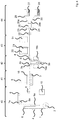
Die
Das Bahnmaterial wird mittels eines Drucktischs 3 in einer Vorschubrichtung 4 durch die Druckvorrichtung bewegt. Hierzu ist der Drucktisch 3 in die Vorschubrichtung 4 sowie entgegen der Vorschubrichtung 4 beweglich. Der Drucktisch 3 ist als zusammenhängende Einheit ausgebildet oder er bewegt sich zumindest als eine Einheit, um einen über die Breite des Bahnmaterials 1 hinweg gleichmäßigen Vorschub des Bahnmaterials 1 zu unterstützen. Der Drucktisch 3 weist eine Halteeinrichtung auf, mittels derer das Bahnmaterial 1 gehalten wird. Während das Bahnmaterial 1 mittels der Halteeinrichtung an dem Drucktisch 3 gehalten wird, bewegt sich der Drucktisch in die Vorschubrichtung 4 von einer hinteren Stellung in eine vordere Stellung und zieht so das Bahnmaterial 1 von der Rolle 2 in Vorschubrichtung 4 durch die Druckvorrichtung. Anschließend gibt die Halteeinrichtung das Bahnmaterial 1 frei, so dass dieses von dem Drucktisch 3 gelöst ist. Der Drucktisch 3 bewegt sich dann entgegen der Vorschubrichtung 4 an dem Bahnmaterial 1 vorbei von der vorderen in die hintere Stellung und bildet anschließend mittels der Halteeinrichtung erneut einen Kontakt zu dem Bahnmaterial 1 aus, worauf sich die Bewegung des Drucktischs 3 in die Vorschubrichtung 4 wiederholt. Es ist so eine diskontinuierliche Fortbewegung des Bahnmaterials 1 durch die Druckvorrichtung bereitgestellt.The web material is moved by means of a printing table 3 in a
In weiteren Ausgestaltungen können zusätzliche Antriebsmechanismen vorgesehen sein, welche die mittels des Drucktischs 3 bereitgestellte Fortbewegung des Bahnmaterials 1 unterstützen. Beispielsweise können angetriebene Rollen, über die das Bahnmaterial 1 verläuft und welche das Bahnmaterial 1 unterstützend fortbewegen, entlang eines Bahnwegs des Bahnmaterials 1 vor und / oder hinter dem Drucktisch 3 angeordnet sein. Insbesondere kann ein unterstützender Antriebsmechanismus entlang des Bahnwegs des Bahnmaterials 1 hinter dem Drucktisch 3 angeordnet sein, um eine Bewegung des Bahnmaterials 1 von dem Drucktisch 3 weg zu unterstützen.In further refinements, additional drive mechanisms can be provided which support the movement of the
Auf einer dem Drucktisch 3 gegenüberliegenden Seite des Bahnmaterials 1 ist ein Drucckopfshuttle 5 angeordnet. Das Druckkopfshuttle 5 ist bezüglich des Bahnmaterials 1 dem Drucktisch 3 derart gegenüberliegend angeordnet, dass das Bahnmaterial 1 zwischen dem Drucktisch 3 und dem Druckkopfshuttle 5 verläuft, sodass es mittels des Druckkopfshuttles 5 bedruckt werden kann, während es auf dem Drucktisch 3 aufliegt und von der Halteeinrichtung gehalten wird. Der Drucktisch 3 bewegt das Bahnmaterial in der Vorschubrichtung 4 an dem Druckkopfshuttle 5 vorbei. Während der Bewegung des Bahnmaterials bedruckt das Druckkopfshuttle 5 das Bahnmaterial 1.A
Bei der Bewegung durch die Druckvorrichtung verläuft das Bahnmaterial 1 über mehrere Umlenkrollen 6, mittels derer das Bahnmaterial 1 innerhalb der Druckvorrichtung umgelenkt wird. Das Bahnmaterial verläuft auch über Bahnspannungsmessrollen 7, mittels derer eine Bahnspannung des Bahnmaterials 1 gemessen wird. Wie in der
Weiterhin verläuft das Bahnmaterial über so genannte Tänzer 9. Hierbei handelt es sich um Rollen, welche beweglich angeordnet sind, um eine Spannung des Bahnmaterials 1 einzustellen. Wie in der
Ein zweiter Tänzer 9b ist entlang des Bahnwegs des Bahnmaterials 1 hinter dem Drucktisch angeordnet. Auch der zweite Tänzer 9b ist in dem gezeigten Beispiel nach oben und unten beweglich, wobei eine Bewegung des zweiten Tänzers 9b nach unten zu einer Erhöhung der Spannung des Bahnmaterials 1 führt und eine Bewegung des zweiten Tänzers 9b nach oben zu einer Verringerung der Spannung des Bahnmaterials 1 führt. Somit lässt sich mittels des zweiten Tänzers 9b die Bahnspannung des Bahnmaterials 1 hinter dem Drucktisch 3 einstellen, welche zumindest während des Haltens des Bahnmaterials 1 mittels der Halteeinrichtung an dem Drucktisch 3 von der Bahnspannung vor dem Drucktisch 3 unabhängig ist.A
Eine Steuervorrichtung 10 ist mit den Bahnspannungsmessrollen 7a, 7b und den Tänzern 9a, 9b verbunden (nicht gezeigt) und eingerichtet, die ersten und die zweiten Messdaten von den Bahnspannungsmessrollen 7a, 7b zu empfangen. In der Steuervorrichtung 10 werden die ersten Messdaten mit einer ersten vorgegebenen Bahnspannung verglichen. Die erste vorgegeben Bahnspannung gibt eine gewünschte Bahnspannung des Bahnmaterials 1 entlang des Bahnwegs des Bahnmaterials 1 vor dem Drucktisch an. Die Steuervorrichtung 10 erzeugt dem Vergleichsergebnis entsprechende erste Steuerdaten, die an den ersten Tänzer 9a übertragen werden und zu einer Bewegung des ersten Tänzers 9a führen. Beispielsweise geben die ersten Steuerdaten eine kleine Bewegung des ersten Tänzers 9a nach unten an, wenn der Vergleich ergibt, dass die Bahnspannung des Bahnmaterials an der ersten Bahnspannungsmessrolle 7a um eine kleine Differenz nach unten von der ersten vorgegebenen Bahnspannung abweicht und die ersten Steuerdaten geben eine größere Bewegung des ersten Tänzers 9a nach oben an, wenn der Vergleich ergibt, dass die Bahnspannung des Bahnmaterials an der ersten Bahnspannungsmessrolle 7a um eine größere Differenz nach oben von der ersten vorgegebenen Bahnspannung abweicht.A
Die Steuervorrichtung 10 ist weiter eingerichtet, die zweiten Messdaten mit einer zweiten vorgegebenen Bahnspannung zu vergleichen. Die zweite vorgegeben Bahnspannung gibt eine gewünschte Bahnspannung des Bahnmaterials 1 entlang des Bahnwegs des Bahnmaterials 1 hinter dem Drucktisch an. Die Steuervorrichtung 10 erzeugt dem Vergleichsergebnis entsprechende zweite Steuerdaten, die an den zweiten Tänzer 9b übertragen werden und zu einer Bewegung des zweiten Tänzers 9b führen. Wie oben bezüglich des ersten Tänzers 9a erläutert, geben beispielsweise die zweiten Steuerdaten eine kleine Bewegung des zweiten Tänzers 9b nach unten an, wenn der Vergleich ergibt, dass die Bahnspannung des Bahnmaterials an der zweiten Bahnspannungsmessrolle 7b um eine kleine Differenz nach unten von der zweiten vorgegebenen Bahnspannung abweicht und die zweiten Steuerdaten geben eine größere Bewegung des zweiten Tänzers 9b nach oben an, wenn der Vergleich ergibt, dass die Bahnspannung des Bahnmaterials an der zweiten Bahnspannungsmessrolle 7b um eine größere Differenz nach oben von der zweiten vorgegebenen Bahnspannung abweicht.The
Es kann eine kontinuierliche Überwachung der Bahnspannungen vor und hinter dem Drucktisch 3 erfolgen, indem wiederholt erste und zweite Messdaten empfangen und entsprechende erste und zweite Steuerdaten erzeugt werden. Hierdurch kann eine Regelung der Bahnspannung in der Druckvorrichtung, entlang des Bahnwegs des Bahnmaterials 1 sowohl vor als auch hinter dem Drucktisch 3, bereitgestellt sein. Beispielsweise können die erste und die zweite vorgegebene Bahnspannung gleich sein und die Bahnspannung des Bahnmaterials 1 sowohl vor als auch hinter dem Drucktisch 3 derart geregelt sein, dass vor und hinter dem Drucktisch 3 die gleiche Bahnspannung des Bahnmaterials 1 innerhalb einer vorgegeben zulässigen Abweichung erreicht wird.The web tension in front of and behind the printing table 3 can be continuously monitored by repeatedly receiving first and second measurement data and generating corresponding first and second control data. In this way, regulation of the web tension in the printing device can be provided along the path of the
Die
Um ein gleichmäßiges Halten des Bahnmaterials 1 auf der Auflagefläche 13 zu gewährleisten, sind Öffnungen der Kanäle 12 über die gesamte Auflagefläche 13 verteilt. In dem Beispiel der
Als weitere Alternative kann die Haltevorrichtung nicht als eine Vakuumvorrichtung 11 bereitgestellt sein. Beispielsweise kann die Haltevorrichtung mittels eines oder mehrerer Greifer bereitgestellt sein, welche das Bahnmaterial 1 greifen und auf der Auflagefläche 13 des Drucktischs 3 halten.As a further alternative, the holding device cannot be provided as a
Während der Bewegung des Bahnmaterials 1 auf dem Drucktisch 3 an dem Druckkopfshuttle 5 vorbei, bedruckt das Druckkopfshuttle 5 das Bahnmaterial 1 mit einem Druckmittel. Hierzu weist das Druckkopfshuttle einen oder mehrere Druckköpfe 14 auf. In der Darstellung der
Die Druckköpfe 14 werden selektiv angesteuert, um selektiv Druckmittel auf das Bahnmaterial 1 aufzubringen und so ein gewünschtes Druckbild auf dem Bahnmaterial zu erzeugen. Hierbei bewegt sich das Druckkopfshuttle 5 quer zur Vorschubrichtung 4 des Bahnmaterials 1 vor und zurück, so dass sich die Druckköpfe 14 über das Bahnmaterial 1 bewegen. Es sind somit durch die Bewegung des Drucktischs 3 entlang der Vorschubrichtung 4 eine Relativbewegung des Bahnmaterials 1 zu den Druckköpfen 14 in einer ersten Druckrichtung und durch die Bewegung des Druckkopfshuttles 5 quer zu der Vorschubrichtung 4 eine Relativbewegung des Bahnmaterials 1 zu den Druckköpfen 14 in einer zweiten Druckrichtung bereitgestellt, die quer zu der ersten Druckrichtung verläuft. Durch eine selektive Steuerung der Bewegung des Drucktischs 3, der Bewegung des Druckkopfshuttles 5 sowie dem Ausstoß der Druckmittels aus den Druckköpfen 14 wird somit ein gewünschtes Druckbild auf das Bahnmaterial 1 aufgebracht.The print heads 14 are selectively activated in order to selectively apply printing medium to the
In Abhängigkeit von dem verwendeten Bahnmaterial 1 und dem verwendeten Druckmittel kann es vorteilhaft sein, das Bahnmaterial 1 zum Bedrucken auf eine bestimmte Temperatur zu bringen. Hierzu weist der Drucktisch 3 gemäß der
Das Druckkopfshuttle 5 weist weiter eine Glättvorrichtung auf. In den Darstellungen der
Bei einem Druckvorgang wird, während sich der Drucktisch 3 in der hinteren Stellung befindet, mittels der Vakuumvorrichtung 11 eine Verbindung zwischen dem Bahnmaterial 1 und der Auflagefläche 13 ausgebildet. Die gemäß der
Nachdem die Bürste 16 über die gesamte Breite des Bahnmaterials 1 bewegt wurde, wird die Bürste 16 in die zweite Stellung gebracht. Bei anschließenden Bewegungen des Drucckopfshuttles 5, während der Bewegung des Drucktischs 3 von der hinteren in die vordere Stellung, tritt die Bürste 16 somit nicht in Kontakt mit dem Bahnmaterial 1. Nach dem Lösen des Bahnmaterials 1 von dem Drucktisch 3 und der Bewegung des Drucktischs 3 von der vorderen in die hintere Stellung wird erneut eine Verbindung zwischen dem Bahnmaterial 1 und der Auflagefläche 13 ausgebildet und die Bürste 16 in die erste Stellung bewegt. Somit wird das Bahnmaterial nach jedem Ausbilden eines Kontakts mit der Auflagefläche 13 des Drucktischs 3 während der ersten anschließenden Bewegung des Druckkopfshuttles 5 über das Bahnmaterial 1 durch die Bürste 16 geglättet.After the
Die Bürste 16 weist eine Länge auf, welche mindestens der Länge der Auflagefläche 13 des Drucktischs 3 entspricht. Hierbei kann, wie in der
Optional kann eine Capping-Station 17 vorgesehen sein, welche ein Austrocknen der Druccköpfe 14 verhindert. Bei Nichtbenutzung der Druckvorrichtung wird das Druckkopfshuttle 5 in eine Stellung gefahren, in der die Druckköpfe 14 durch die Capping-Station 17 von der Umgebung abgeschirmt sind und somit ein Austrocknen der Druckköpfe 14 durch Verdampfen von Lösungsmittel des Druckmittels verhindert ist. Weiterhin kann optional ein Druckmittelbehälter 18 für das Reinigen und / oder Vorbereiten der Druckköpfe 14 für einen Druckvorgang vorgesehen sein. Das Druckkopfshuttle kann in eine Stellung bewegt werden, in der sich die Druckköpfe 14 über dem Druckmittelbehälter 18 befinden. Anschließend kann aus den Druckköpfen 14 Druckmittel in die Druckmittelbehälter 18 ausgestoßen werden, um die die Druckköpfe 14 von Verunreinigungen und / oder Druckmittelresten zu befreien und / oder um Luft aus Transportwegen des Druckmittels in den Druckköpfen 14 entfernen.A
Wie in der
Die
Eine Übereinstimmung zwischen dem Druckbild und den Vergleichs-Bilddaten wird festgestellt, wenn das aufgenommene Bild des Druckbilds auf dem Bahnmaterial 1 den Vergleichs-Bilddaten innerhalb vorbestimmter Grenzen entspricht. Entspricht das aufgenommene Bild des Druckbilds auf dem Bahnmaterial 1 den Vergleichs-Bilddaten nicht innerhalb der vorbestimmten Grenzen, wird keine Übereinstimmung zwischen dem Druckbild und den Vergleichs-Bilddaten festgestellt. Der Vergleich des aufgenommenen Bilds mit den Vergleichs-Bilddaten kann beispielsweise ein Pixel-Vergleich und / oder ein Vergleich kennzeichnender Werte des aufgenommenen Bilds, beispielsweise ein Kontrastwert, sein.A correspondence between the print image and the comparison image data is established when the recorded image of the print image on the
Zur Unterstützung der Fortbewegung des Bahnmaterials 1 ist entlang der Bewegungsbahn des Bahnmaterials 1 hinter der Prüfvorrichtung 21 ein Rollenantrieb 22 angeordnet. Hinter dem Rollenantrieb 22 ist ein weiterer Tänzer 9c zur Steuerung der Bahnspannung des Bahnmaterials 1 angeordnet. Der weitere Tänzer 9c kann beispielsweise von der Steuervorrichtung 10 entsprechend den zweiten Sensordaten angesteuert werden. Alternativ kann eine weitere Bahnspannungsmessrolle vorgesehen sein, welche dritte Messdaten erzeugt, mittels derer die Steuervorrichtung 10 den weiteren Tänzer 9c ansteuert.To support the movement of the
Entlang der Bewegungsbahn des Bahnmaterials 1 hinter der Prüfvorrichtung 21 und dem weiteren Tänzer 9c ist eine Konfektioniereinrichtung 23 angeordnet, die eingerichtet ist, das Bahnmaterial 1 zu einzelnen Bögen zu konfektionieren. Beispielsweise kann das Bahnmaterial 1 der Konfektioniereinrichtung 23 zugeführt werden und mittels einer Schneideinrichtung 24 der Konfektioniereinrichtung 23 auf eine vorbestimmte Bogengröße zugeschnitten werden, um das Bahnmaterial 1 zu einzelnen Bögen zu konfektionieren. Anschließend werden die einzelnen Bögen in einer Dokumentenweiche 25 auf unterschiedliche Transportwege 26a, 26b gelenkt. Ein Transportweg 26a führt in einen Dokumentenbehälter 27. Ein weiterer Transportweg 26b führt in einen Ausschussbehälter 28. Bögen, die ein Druckbild tragen, welches als korrektes Druckbild bestimmt wurde, werden als Dokumentenbogen 29 bestimmt und von der Dokumentenweiche 25 auf den Transportweg 26a geleitet, der in den Dokumentenbehälter 27 führt. Bögen, die ein Druckbild tragen, welches als nicht-korrektes Druckbild bestimmt wurde, werden als Makulatur-Bogen 30 bestimmt und von der Dokumentenweiche 25 auf den Transportweg 26b geleitet, der in den Ausschussbehälter 28 führt. Auf diese Weise kann eine Aussortierung von Druckbögen erfolgen, welche Fehler im Druckbild aufweisen. Es kann anschließend ein erneuter Druck des Druckbilds eines Makulatur-Bogens 30 erfolgen.Arranged along the path of movement of the
Optional kann eine Schlechtmarkierungs-Vorrichtung 31 vorgesehen sein, welche entlang der Bewegungsbahn des Bahnmaterials 1 hinter der Prüfvorrichtung 21 und vor der Konfektioniereinrichtung 23 angeordnet ist. Die Schlechtmarkierungs-Vorrichtung 31 ist eingerichtet, auf ein Druckbild, welches als nicht-korrektes Druckbild bestimmt wurde, mit einer Markierung zu versehen, welche das Druckbild als nicht-korrektes Druckbild kennzeichnet. Beispielsweise kann die Schlechtmarkierungs-Vorrichtung 31 hierzu einen Druckkopf umfassen.Optionally, a
Es kann vorgesehen sein, dass das Druckbild mehrere Einzel-Druckbilder umfasst. In diesem Fall kann jedes Einzel-Druckbild als korrektes Einzel-Druckbild oder nicht-korrektes Einzel-Druckbild bestimmt werden und die Schlechtmarkierungs-Vorrichtung 31 kann eingerichtet sein, jedes als nicht-korrektes Einzel-Druckbild bestimmtes Einzel-Druckbild mit einer Markierung zu versehen, welche das Einzel-Druckbild als nicht-korrektes Einzel-Druckbild kennzeichnet. In diesem Fall kann die Dokumentenweiche 25 entfallen und alle vereinzelten Bögen können über den Transportweg 26a dem Dokumentenbehälter 27 zugeführt werden.It can be provided that the print image comprises several individual print images. In this case, each individual print image can be determined as a correct individual print image or incorrect individual print image and the
Alternativ kann die Dokumentenweiche 25 vorgesehen und eingerichtet sein, Druckbögen mit einem Druckbild, das eine Anzahl an als nicht-korrekte Einzel-Druckbilder gekennzeichneten Einzel-Druckbildern umfasst, die eine vorbestimmte Höchstzahl an nicht-korrekten Einzel-Druckbildern übersteigt, über den Transportweg 26b dem Ausschussbehälter 28 zuzuführen und andere Bögen über den Transportweg 26a dem Dokumentenbehälter 27 zuzuführen.Alternatively, the
Die
Die in der vorstehenden Beschreibung, den Ansprüchen sowie der Zeichnung offenbarten Merkmale können sowohl einzeln als auch in beliebiger Kombination für die Verwirklichung der verschiedenen Ausführungen von Bedeutung sein.The features disclosed in the above description, the claims and the drawing can be of importance both individually and in any combination for the implementation of the various designs.
- 11
- BahnmaterialRailway material
- 22
- Rollerole
- 33
- DrucktischPrinting table
- 44th
- VorschubrichtungFeed direction
- 55
- DruckkopfshuttlePrint head shuttle
- 66
- UmlenkrollenPulleys
- 7a, 7b7a, 7b
- BahnspannungsmessrolleWeb tension measuring roller
- 8a, 8b8a, 8b
- SensoreinrichtungSensor device
- 9a, 9b, 9c9a, 9b, 9c
- Tänzerdancer
- 1010
- SteuervorrichtungControl device
- 1111
- VakuumvorrichtungVacuum device
- 1212th
- Kanälechannels
- 1313th
- AuflageflächeContact surface
- 14a, 14b14a, 14b
- DruckköpfePrint heads
- 1515
- HeizeinrichtungHeating device
- 1616
- Bürstebrush
- 1717th
- Capping-StationCapping station
- 1818th
- DruckmittelbehälterPressure medium tank
- 19a, 19b19a, 19b
- TrocknungseinrichtungDrying device
- 2020th
- PrüfvorrichtungTesting device
- 2121st
- BildaufnahmevorrichtungImage capture device
- 2222nd
- RollenantriebRoller drive
- 2323
- KonfektioniereinrichtungAssembly device
- 2424
- SchneideinrichtungCutting device
- 2525
- DokumentenweicheDocument switch
- 26a, 26b26a, 26b
- TransportwegeTransport routes
- 2727
- DokumentenbehälterDocument tray
- 2828
- AusschussbehälterReject bin
- 2929
- DokumentenbogenDocument sheet
- 3030th
- Makulatur-BogenWaste sheets
- 3131
- Schlechtmarkierungs-VorrichtungBad marking device
- 4040
- RollenabwickelmodulRoll unwind module
- 4141
- DruckmodulPrint module
- 4242
- TrocknungsmodulDrying module
- 4343
- BildverabeitungsmodulImage processing module
- 4444
- KonfektionierungsmodulAssembly module
Claims (15)
wobei der Drucktisch (3) eine Halteeinrichtung (11) umfasst, die eingerichtet ist, das Drucksubstrat (1) zu halten, derart, dass zum Bedrucken eine Relativbewegung zwischen dem Drucktisch (3) und dem Drucksubstrat (1) verhindert ist; und
wobei der Drucktisch (3) eingerichtet ist, eine Vorschubbewegung auszuführen, während die Halteeinrichtung (11) das Drucksubstrat (1) hält, derart, dass die Vorschubbewegung auf das Drucksubstrat (1) übertragen wird und der Drucktisch (3) eine Vorschubbewegung des Drucksubstrats (1) entlang des Bahnwegs bewirkt.
wherein the printing table (3) comprises a holding device (11) which is set up to hold the printing substrate (1) in such a way that a relative movement between the printing table (3) and the printing substrate (1) is prevented for printing; and
wherein the printing table (3) is set up to carry out a feed movement while the holding device (11) holds the printing substrate (1) in such a way that the feed movement is transmitted to the printing substrate (1) and the printing table (3) a feed movement of the printing substrate ( 1) along the railway path.
wobei vorzugsweise die Porosität des Materials eine definierte Porosität ist oder die Kanäle in einem definierten Raster von Bohrungen bereitgestellt sind.Device according to claim 6, characterized in that at least a section of the printing table (3) which comprises the support surface comprises a porous material, the channels which connect the vacuum device to the support surface being provided by the porosity of the material,
wherein the porosity of the material is preferably a defined porosity or the channels are provided in a defined grid of bores.
Applications Claiming Priority (1)
| Application Number | Priority Date | Filing Date | Title |
|---|---|---|---|
| DE102019103156.7A DE102019103156A1 (en) | 2019-02-08 | 2019-02-08 | Device and method for printing on a print substrate |
Publications (2)
| Publication Number | Publication Date |
|---|---|
| EP3693178A1 true EP3693178A1 (en) | 2020-08-12 |
| EP3693178B1 EP3693178B1 (en) | 2023-10-04 |
Family
ID=69528612
Family Applications (1)
| Application Number | Title | Priority Date | Filing Date |
|---|---|---|---|
| EP20156184.2A Active EP3693178B1 (en) | 2019-02-08 | 2020-02-07 | Device and method for printing a print substrate |
Country Status (2)
| Country | Link |
|---|---|
| EP (1) | EP3693178B1 (en) |
| DE (1) | DE102019103156A1 (en) |
Cited By (2)
| Publication number | Priority date | Publication date | Assignee | Title |
|---|---|---|---|---|
| EP4005810A1 (en) | 2020-11-26 | 2022-06-01 | Bundesdruckerei GmbH | Method and device for printing an endless material from a roll of material |
| DE102022100765A1 (en) | 2022-01-13 | 2023-07-13 | Bundesdruckerei Gmbh | Printing device for printing a web-shaped substrate |
Citations (12)
| Publication number | Priority date | Publication date | Assignee | Title |
|---|---|---|---|---|
| EP0167196A1 (en) * | 1984-07-05 | 1986-01-08 | De La Rue Giori S.A. | Method of converting webs or sheets of securities into bundles of securities |
| DE4221966A1 (en) | 1992-06-30 | 1994-01-05 | Rotring Int Gmbh | Sheet-cutting and drawing machine - has members in two groups movable independently in feed direction and forming working surface |
| DE19681284B4 (en) | 1995-03-16 | 2004-10-28 | Rohm Co. Ltd. | Card printer for printing on cards using a card printer |
| DE102006015828A1 (en) * | 2006-04-03 | 2007-10-04 | Man Roland Druckmaschinen Ag | Image inspection system for e.g. sheet-fed offset press, has sorting device, where data, which are stored in memory and obtained by image processing algorithm, are stored in another memory for analysis by algorithm |
| JP2008012812A (en) * | 2006-07-06 | 2008-01-24 | Mimaki Engineering Co Ltd | Printer, carrier, and printing method |
| US7744210B2 (en) | 2005-05-09 | 2010-06-29 | Agfa Graphics Nv | Moving floor media transport for digital printers |
| DE102009003445A1 (en) * | 2009-02-05 | 2010-09-09 | Theodor Hymmen Holding Gmbh | Web i.e. paper web, printing method, involves moving slides relative to color application device in feed direction, and printing strip-shaped sections, and winding printed web on roll |
| US20120042799A1 (en) * | 2010-08-20 | 2012-02-23 | Seiko Epson Corporation | Recording device and workpiece-advancing/retracting method for recording device |
| DE102016102566A1 (en) | 2016-02-15 | 2017-08-17 | Bundesdruckerei Gmbh | Method and apparatus for printing a singulated sheet in a printing device |
| DE102016102565A1 (en) | 2016-02-15 | 2017-08-17 | Bundesdruckerei Gmbh | Method and device for producing a singulated sheet in a printing device |
| EP3335894A1 (en) * | 2016-12-16 | 2018-06-20 | OCE Holding B.V. | Printer with image inspection device |
| JP2018165001A (en) | 2017-03-28 | 2018-10-25 | 株式会社トライテック | Industrial inkjet drawing apparatus |
Family Cites Families (5)
| Publication number | Priority date | Publication date | Assignee | Title |
|---|---|---|---|---|
| DE102006001826B4 (en) * | 2006-01-13 | 2010-08-19 | Koenig & Bauer Aktiengesellschaft | Method for controlling a length of a transport path of a printing material web |
| DE102008064629A1 (en) * | 2008-05-15 | 2009-12-10 | Koenig & Bauer Aktiengesellschaft | A method for controlling a web tension during a Einziehvorganges a material attached to a pulling-in material web in a rotary printing machine |
| GB0907362D0 (en) * | 2009-04-29 | 2009-06-10 | Ten Cate Itex B V | Print carriage |
| US9102136B2 (en) * | 2010-01-13 | 2015-08-11 | Mimaki Engineering Company, Ltd. | Ink-jet printer and medium transfer method |
| JP2015182394A (en) * | 2014-03-25 | 2015-10-22 | セイコーエプソン株式会社 | Printer and printing method |
-
2019
- 2019-02-08 DE DE102019103156.7A patent/DE102019103156A1/en active Pending
-
2020
- 2020-02-07 EP EP20156184.2A patent/EP3693178B1/en active Active
Patent Citations (12)
| Publication number | Priority date | Publication date | Assignee | Title |
|---|---|---|---|---|
| EP0167196A1 (en) * | 1984-07-05 | 1986-01-08 | De La Rue Giori S.A. | Method of converting webs or sheets of securities into bundles of securities |
| DE4221966A1 (en) | 1992-06-30 | 1994-01-05 | Rotring Int Gmbh | Sheet-cutting and drawing machine - has members in two groups movable independently in feed direction and forming working surface |
| DE19681284B4 (en) | 1995-03-16 | 2004-10-28 | Rohm Co. Ltd. | Card printer for printing on cards using a card printer |
| US7744210B2 (en) | 2005-05-09 | 2010-06-29 | Agfa Graphics Nv | Moving floor media transport for digital printers |
| DE102006015828A1 (en) * | 2006-04-03 | 2007-10-04 | Man Roland Druckmaschinen Ag | Image inspection system for e.g. sheet-fed offset press, has sorting device, where data, which are stored in memory and obtained by image processing algorithm, are stored in another memory for analysis by algorithm |
| JP2008012812A (en) * | 2006-07-06 | 2008-01-24 | Mimaki Engineering Co Ltd | Printer, carrier, and printing method |
| DE102009003445A1 (en) * | 2009-02-05 | 2010-09-09 | Theodor Hymmen Holding Gmbh | Web i.e. paper web, printing method, involves moving slides relative to color application device in feed direction, and printing strip-shaped sections, and winding printed web on roll |
| US20120042799A1 (en) * | 2010-08-20 | 2012-02-23 | Seiko Epson Corporation | Recording device and workpiece-advancing/retracting method for recording device |
| DE102016102566A1 (en) | 2016-02-15 | 2017-08-17 | Bundesdruckerei Gmbh | Method and apparatus for printing a singulated sheet in a printing device |
| DE102016102565A1 (en) | 2016-02-15 | 2017-08-17 | Bundesdruckerei Gmbh | Method and device for producing a singulated sheet in a printing device |
| EP3335894A1 (en) * | 2016-12-16 | 2018-06-20 | OCE Holding B.V. | Printer with image inspection device |
| JP2018165001A (en) | 2017-03-28 | 2018-10-25 | 株式会社トライテック | Industrial inkjet drawing apparatus |
Cited By (4)
| Publication number | Priority date | Publication date | Assignee | Title |
|---|---|---|---|---|
| EP4005810A1 (en) | 2020-11-26 | 2022-06-01 | Bundesdruckerei GmbH | Method and device for printing an endless material from a roll of material |
| DE102020131378A1 (en) | 2020-11-26 | 2022-06-02 | Bundesdruckerei Gmbh | Method and device for printing a continuous material from a roll of material |
| DE102022100765A1 (en) | 2022-01-13 | 2023-07-13 | Bundesdruckerei Gmbh | Printing device for printing a web-shaped substrate |
| EP4212349A1 (en) * | 2022-01-13 | 2023-07-19 | Bundesdruckerei GmbH | Printing device for printing a web-shaped substrate |
Also Published As
| Publication number | Publication date |
|---|---|
| EP3693178B1 (en) | 2023-10-04 |
| DE102019103156A1 (en) | 2020-08-13 |
Similar Documents
| Publication | Publication Date | Title |
|---|---|---|
| EP1317342B1 (en) | Ink jet printing device | |
| EP2714409B1 (en) | Printing machine | |
| DE102011006139B4 (en) | Media transport system for transporting a sheet of media through a print zone and method of operating the media transport system | |
| EP1313618B1 (en) | Unit for the continuous production of printed textile strips, in particular printed label strips | |
| EP2508353A2 (en) | Method for manufacturing books, in particular photo books and/or image strips | |
| EP3693178B1 (en) | Device and method for printing a print substrate | |
| EP3416905B1 (en) | Method and device for producing a single sheet in a printing device | |
| DE102009041146A1 (en) | inkjet | |
| EP3693177B1 (en) | Device and method for printing a print substrate | |
| EP1307344A1 (en) | Ink-jet printer and method for printing image material in an ink-jet printer | |
| EP3693174B1 (en) | Device and method for printing a print substrate | |
| DE102016209280A1 (en) | Device for printing a web of printing material | |
| EP3693175B1 (en) | Device and method for printing a print substrate | |
| DE102010060489B4 (en) | Apparatus for drying an ink-printed record carrier in a printer and method therefor | |
| EP3693169B1 (en) | Device and method for assembling and sorting a printing substrate | |
| DE10330847A1 (en) | print mechanism | |
| DE2328510C3 (en) | Device for feeding sheet-like recording media to typewriters and similar machines | |
| DE102020105126A1 (en) | Sheet transport device with an elastically deformable support surface for transferring sheets between two conveyors in a printing system | |
| EP4005810B1 (en) | Method and device for printing an endless material from a roll of material | |
| EP3426583B1 (en) | Device for linearly correcting the transportation of support media | |
| DE3149879A1 (en) | Bar code printing method | |
| EP3003721B1 (en) | Method for reprinting at least one individualised print copy | |
| DE102019106548A1 (en) | Method for determining a deviation of at least one print head and / or at least one sensor device of a printing press and a print control strip | |
| DE102019132581A1 (en) | WIDE SECTION REMOVAL AID FOR WIDE FORMAT ROLL PRINTER | |
| DE102023119623A1 (en) | Printer with definition roll for an endless belt |
Legal Events
| Date | Code | Title | Description |
|---|---|---|---|
| PUAI | Public reference made under article 153(3) epc to a published international application that has entered the european phase |
Free format text: ORIGINAL CODE: 0009012 |
|
| STAA | Information on the status of an ep patent application or granted ep patent |
Free format text: STATUS: THE APPLICATION HAS BEEN PUBLISHED |
|
| AK | Designated contracting states |
Kind code of ref document: A1 Designated state(s): AL AT BE BG CH CY CZ DE DK EE ES FI FR GB GR HR HU IE IS IT LI LT LU LV MC MK MT NL NO PL PT RO RS SE SI SK SM TR |
|
| AX | Request for extension of the european patent |
Extension state: BA ME |
|
| STAA | Information on the status of an ep patent application or granted ep patent |
Free format text: STATUS: REQUEST FOR EXAMINATION WAS MADE |
|
| 17P | Request for examination filed |
Effective date: 20210122 |
|
| RBV | Designated contracting states (corrected) |
Designated state(s): AL AT BE BG CH CY CZ DE DK EE ES FI FR GB GR HR HU IE IS IT LI LT LU LV MC MK MT NL NO PL PT RO RS SE SI SK SM TR |
|
| STAA | Information on the status of an ep patent application or granted ep patent |
Free format text: STATUS: EXAMINATION IS IN PROGRESS |
|
| 17Q | First examination report despatched |
Effective date: 20220824 |
|
| GRAP | Despatch of communication of intention to grant a patent |
Free format text: ORIGINAL CODE: EPIDOSNIGR1 |
|
| STAA | Information on the status of an ep patent application or granted ep patent |
Free format text: STATUS: GRANT OF PATENT IS INTENDED |
|
| INTG | Intention to grant announced |
Effective date: 20230509 |
|
| P01 | Opt-out of the competence of the unified patent court (upc) registered |
Effective date: 20230526 |
|
| GRAS | Grant fee paid |
Free format text: ORIGINAL CODE: EPIDOSNIGR3 |
|
| GRAA | (expected) grant |
Free format text: ORIGINAL CODE: 0009210 |
|
| STAA | Information on the status of an ep patent application or granted ep patent |
Free format text: STATUS: THE PATENT HAS BEEN GRANTED |
|
| AK | Designated contracting states |
Kind code of ref document: B1 Designated state(s): AL AT BE BG CH CY CZ DE DK EE ES FI FR GB GR HR HU IE IS IT LI LT LU LV MC MK MT NL NO PL PT RO RS SE SI SK SM TR |
|
| REG | Reference to a national code |
Ref country code: GB Ref legal event code: FG4D Free format text: NOT ENGLISH |
|
| REG | Reference to a national code |
Ref country code: CH Ref legal event code: EP |
|
| REG | Reference to a national code |
Ref country code: DE Ref legal event code: R096 Ref document number: 502020005465 Country of ref document: DE |
|
| REG | Reference to a national code |
Ref country code: IE Ref legal event code: FG4D Free format text: LANGUAGE OF EP DOCUMENT: GERMAN |
|
| REG | Reference to a national code |
Ref country code: LT Ref legal event code: MG9D |
|
| REG | Reference to a national code |
Ref country code: NL Ref legal event code: MP Effective date: 20231004 |
|
| PG25 | Lapsed in a contracting state [announced via postgrant information from national office to epo] |
Ref country code: NL Free format text: LAPSE BECAUSE OF FAILURE TO SUBMIT A TRANSLATION OF THE DESCRIPTION OR TO PAY THE FEE WITHIN THE PRESCRIBED TIME-LIMIT Effective date: 20231004 |
|
| PG25 | Lapsed in a contracting state [announced via postgrant information from national office to epo] |
Ref country code: GR Free format text: LAPSE BECAUSE OF FAILURE TO SUBMIT A TRANSLATION OF THE DESCRIPTION OR TO PAY THE FEE WITHIN THE PRESCRIBED TIME-LIMIT Effective date: 20240105 |
|
| PG25 | Lapsed in a contracting state [announced via postgrant information from national office to epo] |
Ref country code: IS Free format text: LAPSE BECAUSE OF FAILURE TO SUBMIT A TRANSLATION OF THE DESCRIPTION OR TO PAY THE FEE WITHIN THE PRESCRIBED TIME-LIMIT Effective date: 20240204 |
|
| PG25 | Lapsed in a contracting state [announced via postgrant information from national office to epo] |
Ref country code: LT Free format text: LAPSE BECAUSE OF FAILURE TO SUBMIT A TRANSLATION OF THE DESCRIPTION OR TO PAY THE FEE WITHIN THE PRESCRIBED TIME-LIMIT Effective date: 20231004 |