EP3693115A1 - Réparation des dommages causés par des trous traversants à l'aide d'une préforme frittée par brasage - Google Patents
Réparation des dommages causés par des trous traversants à l'aide d'une préforme frittée par brasage Download PDFInfo
- Publication number
- EP3693115A1 EP3693115A1 EP20154640.5A EP20154640A EP3693115A1 EP 3693115 A1 EP3693115 A1 EP 3693115A1 EP 20154640 A EP20154640 A EP 20154640A EP 3693115 A1 EP3693115 A1 EP 3693115A1
- Authority
- EP
- European Patent Office
- Prior art keywords
- braze
- base component
- sintered preform
- maximum
- braze sintered
- Prior art date
- Legal status (The legal status is an assumption and is not a legal conclusion. Google has not performed a legal analysis and makes no representation as to the accuracy of the status listed.)
- Pending
Links
- 229910045601 alloy Inorganic materials 0.000 claims abstract description 63
- 239000000956 alloy Substances 0.000 claims abstract description 63
- PXHVJJICTQNCMI-UHFFFAOYSA-N Nickel Chemical compound [Ni] PXHVJJICTQNCMI-UHFFFAOYSA-N 0.000 claims abstract description 40
- 238000000034 method Methods 0.000 claims abstract description 35
- 238000010438 heat treatment Methods 0.000 claims abstract description 22
- 229910052759 nickel Inorganic materials 0.000 claims abstract description 21
- 229910000601 superalloy Inorganic materials 0.000 claims abstract description 13
- 239000000463 material Substances 0.000 claims description 166
- 239000000843 powder Substances 0.000 claims description 77
- 239000000203 mixture Substances 0.000 claims description 37
- 229910052796 boron Inorganic materials 0.000 claims description 19
- 229910052782 aluminium Inorganic materials 0.000 claims description 18
- 229910052804 chromium Inorganic materials 0.000 claims description 18
- 229910052710 silicon Inorganic materials 0.000 claims description 18
- 229910052721 tungsten Inorganic materials 0.000 claims description 18
- 229910052702 rhenium Inorganic materials 0.000 claims description 17
- 229910052715 tantalum Inorganic materials 0.000 claims description 17
- 229910052735 hafnium Inorganic materials 0.000 claims description 16
- 229910052750 molybdenum Inorganic materials 0.000 claims description 15
- 229910052758 niobium Inorganic materials 0.000 claims description 13
- 239000007789 gas Substances 0.000 claims description 11
- XKRFYHLGVUSROY-UHFFFAOYSA-N Argon Chemical compound [Ar] XKRFYHLGVUSROY-UHFFFAOYSA-N 0.000 claims description 8
- ZOXJGFHDIHLPTG-UHFFFAOYSA-N Boron Chemical compound [B] ZOXJGFHDIHLPTG-UHFFFAOYSA-N 0.000 claims description 6
- 239000010703 silicon Substances 0.000 claims description 6
- 229910052698 phosphorus Inorganic materials 0.000 claims description 5
- 229910052719 titanium Inorganic materials 0.000 claims description 5
- 229910052786 argon Inorganic materials 0.000 claims description 4
- 238000003754 machining Methods 0.000 claims description 4
- 229910052727 yttrium Inorganic materials 0.000 claims description 4
- 229910052799 carbon Inorganic materials 0.000 claims description 3
- 238000009792 diffusion process Methods 0.000 claims description 3
- 229910052697 platinum Inorganic materials 0.000 claims description 3
- 229910052802 copper Inorganic materials 0.000 claims description 2
- 229910052742 iron Inorganic materials 0.000 claims description 2
- 229910052749 magnesium Inorganic materials 0.000 claims description 2
- 229910052757 nitrogen Inorganic materials 0.000 claims description 2
- 229910052760 oxygen Inorganic materials 0.000 claims description 2
- 229910052717 sulfur Inorganic materials 0.000 claims description 2
- 229910052720 vanadium Inorganic materials 0.000 claims description 2
- 238000003466 welding Methods 0.000 claims description 2
- 229910052726 zirconium Inorganic materials 0.000 claims description 2
- VYZAMTAEIAYCRO-UHFFFAOYSA-N Chromium Chemical compound [Cr] VYZAMTAEIAYCRO-UHFFFAOYSA-N 0.000 claims 4
- ZOKXTWBITQBERF-UHFFFAOYSA-N Molybdenum Chemical compound [Mo] ZOKXTWBITQBERF-UHFFFAOYSA-N 0.000 claims 4
- XAGFODPZIPBFFR-UHFFFAOYSA-N aluminium Chemical compound [Al] XAGFODPZIPBFFR-UHFFFAOYSA-N 0.000 claims 4
- 239000011651 chromium Substances 0.000 claims 4
- VBJZVLUMGGDVMO-UHFFFAOYSA-N hafnium atom Chemical compound [Hf] VBJZVLUMGGDVMO-UHFFFAOYSA-N 0.000 claims 4
- 239000011733 molybdenum Substances 0.000 claims 4
- WUAPFZMCVAUBPE-UHFFFAOYSA-N rhenium atom Chemical compound [Re] WUAPFZMCVAUBPE-UHFFFAOYSA-N 0.000 claims 4
- GUVRBAGPIYLISA-UHFFFAOYSA-N tantalum atom Chemical compound [Ta] GUVRBAGPIYLISA-UHFFFAOYSA-N 0.000 claims 4
- WFKWXMTUELFFGS-UHFFFAOYSA-N tungsten Chemical compound [W] WFKWXMTUELFFGS-UHFFFAOYSA-N 0.000 claims 4
- 239000010937 tungsten Substances 0.000 claims 4
- 239000010955 niobium Substances 0.000 claims 3
- GUCVJGMIXFAOAE-UHFFFAOYSA-N niobium atom Chemical compound [Nb] GUCVJGMIXFAOAE-UHFFFAOYSA-N 0.000 claims 3
- IJGRMHOSHXDMSA-UHFFFAOYSA-N Atomic nitrogen Chemical compound N#N IJGRMHOSHXDMSA-UHFFFAOYSA-N 0.000 claims 2
- XEEYBQQBJWHFJM-UHFFFAOYSA-N Iron Chemical compound [Fe] XEEYBQQBJWHFJM-UHFFFAOYSA-N 0.000 claims 2
- BASFCYQUMIYNBI-UHFFFAOYSA-N platinum Chemical compound [Pt] BASFCYQUMIYNBI-UHFFFAOYSA-N 0.000 claims 2
- OKTJSMMVPCPJKN-UHFFFAOYSA-N Carbon Chemical compound [C] OKTJSMMVPCPJKN-UHFFFAOYSA-N 0.000 claims 1
- RYGMFSIKBFXOCR-UHFFFAOYSA-N Copper Chemical compound [Cu] RYGMFSIKBFXOCR-UHFFFAOYSA-N 0.000 claims 1
- FYYHWMGAXLPEAU-UHFFFAOYSA-N Magnesium Chemical compound [Mg] FYYHWMGAXLPEAU-UHFFFAOYSA-N 0.000 claims 1
- OAICVXFJPJFONN-UHFFFAOYSA-N Phosphorus Chemical compound [P] OAICVXFJPJFONN-UHFFFAOYSA-N 0.000 claims 1
- NINIDFKCEFEMDL-UHFFFAOYSA-N Sulfur Chemical compound [S] NINIDFKCEFEMDL-UHFFFAOYSA-N 0.000 claims 1
- RTAQQCXQSZGOHL-UHFFFAOYSA-N Titanium Chemical compound [Ti] RTAQQCXQSZGOHL-UHFFFAOYSA-N 0.000 claims 1
- QCWXUUIWCKQGHC-UHFFFAOYSA-N Zirconium Chemical compound [Zr] QCWXUUIWCKQGHC-UHFFFAOYSA-N 0.000 claims 1
- QVGXLLKOCUKJST-UHFFFAOYSA-N atomic oxygen Chemical compound [O] QVGXLLKOCUKJST-UHFFFAOYSA-N 0.000 claims 1
- 239000010941 cobalt Substances 0.000 claims 1
- 229910017052 cobalt Inorganic materials 0.000 claims 1
- GUTLYIVDDKVIGB-UHFFFAOYSA-N cobalt atom Chemical compound [Co] GUTLYIVDDKVIGB-UHFFFAOYSA-N 0.000 claims 1
- 239000010949 copper Substances 0.000 claims 1
- 239000008240 homogeneous mixture Substances 0.000 claims 1
- 239000011777 magnesium Substances 0.000 claims 1
- WPBNNNQJVZRUHP-UHFFFAOYSA-L manganese(2+);methyl n-[[2-(methoxycarbonylcarbamothioylamino)phenyl]carbamothioyl]carbamate;n-[2-(sulfidocarbothioylamino)ethyl]carbamodithioate Chemical compound [Mn+2].[S-]C(=S)NCCNC([S-])=S.COC(=O)NC(=S)NC1=CC=CC=C1NC(=S)NC(=O)OC WPBNNNQJVZRUHP-UHFFFAOYSA-L 0.000 claims 1
- 239000001301 oxygen Substances 0.000 claims 1
- 239000011574 phosphorus Substances 0.000 claims 1
- 239000011593 sulfur Substances 0.000 claims 1
- 239000010936 titanium Substances 0.000 claims 1
- LEONUFNNVUYDNQ-UHFFFAOYSA-N vanadium atom Chemical compound [V] LEONUFNNVUYDNQ-UHFFFAOYSA-N 0.000 claims 1
- VWQVUPCCIRVNHF-UHFFFAOYSA-N yttrium atom Chemical compound [Y] VWQVUPCCIRVNHF-UHFFFAOYSA-N 0.000 claims 1
- 238000005245 sintering Methods 0.000 description 10
- 239000013078 crystal Substances 0.000 description 6
- 238000010586 diagram Methods 0.000 description 6
- 230000003647 oxidation Effects 0.000 description 5
- 238000007254 oxidation reaction Methods 0.000 description 5
- 238000002844 melting Methods 0.000 description 4
- 239000000126 substance Substances 0.000 description 4
- 229910001011 CMSX-4 Inorganic materials 0.000 description 3
- 238000005219 brazing Methods 0.000 description 3
- 238000001816 cooling Methods 0.000 description 3
- 239000011888 foil Substances 0.000 description 3
- 239000000155 melt Substances 0.000 description 3
- 230000008018 melting Effects 0.000 description 3
- 239000000654 additive Substances 0.000 description 2
- 230000000996 additive effect Effects 0.000 description 2
- 238000005275 alloying Methods 0.000 description 2
- 239000012298 atmosphere Substances 0.000 description 2
- 238000005266 casting Methods 0.000 description 2
- 238000004140 cleaning Methods 0.000 description 2
- 230000007797 corrosion Effects 0.000 description 2
- 238000005260 corrosion Methods 0.000 description 2
- 229910052741 iridium Inorganic materials 0.000 description 2
- 229910052746 lanthanum Inorganic materials 0.000 description 2
- 229910052748 manganese Inorganic materials 0.000 description 2
- 239000002184 metal Substances 0.000 description 2
- 229910052751 metal Inorganic materials 0.000 description 2
- 238000002156 mixing Methods 0.000 description 2
- 229910052763 palladium Inorganic materials 0.000 description 2
- 229910000995 CMSX-10 Inorganic materials 0.000 description 1
- NPXOKRUENSOPAO-UHFFFAOYSA-N Raney nickel Chemical compound [Al].[Ni] NPXOKRUENSOPAO-UHFFFAOYSA-N 0.000 description 1
- 238000007792 addition Methods 0.000 description 1
- 239000012300 argon atmosphere Substances 0.000 description 1
- 230000000712 assembly Effects 0.000 description 1
- 238000000429 assembly Methods 0.000 description 1
- 238000000576 coating method Methods 0.000 description 1
- 239000000470 constituent Substances 0.000 description 1
- 230000009977 dual effect Effects 0.000 description 1
- 238000005242 forging Methods 0.000 description 1
- 238000009689 gas atomisation Methods 0.000 description 1
- 238000000227 grinding Methods 0.000 description 1
- 230000006698 induction Effects 0.000 description 1
- 238000004519 manufacturing process Methods 0.000 description 1
- 150000002739 metals Chemical class 0.000 description 1
- 238000003801 milling Methods 0.000 description 1
- 229910000907 nickel aluminide Inorganic materials 0.000 description 1
- NJPPVKZQTLUDBO-UHFFFAOYSA-N novaluron Chemical compound C1=C(Cl)C(OC(F)(F)C(OC(F)(F)F)F)=CC=C1NC(=O)NC(=O)C1=C(F)C=CC=C1F NJPPVKZQTLUDBO-UHFFFAOYSA-N 0.000 description 1
- 239000002245 particle Substances 0.000 description 1
- 238000004663 powder metallurgy Methods 0.000 description 1
- 238000007493 shaping process Methods 0.000 description 1
- 239000007787 solid Substances 0.000 description 1
Images


Classifications
-
- B—PERFORMING OPERATIONS; TRANSPORTING
- B23—MACHINE TOOLS; METAL-WORKING NOT OTHERWISE PROVIDED FOR
- B23K—SOLDERING OR UNSOLDERING; WELDING; CLADDING OR PLATING BY SOLDERING OR WELDING; CUTTING BY APPLYING HEAT LOCALLY, e.g. FLAME CUTTING; WORKING BY LASER BEAM
- B23K1/00—Soldering, e.g. brazing, or unsoldering
- B23K1/0008—Soldering, e.g. brazing, or unsoldering specially adapted for particular articles or work
- B23K1/0018—Brazing of turbine parts
-
- B—PERFORMING OPERATIONS; TRANSPORTING
- B23—MACHINE TOOLS; METAL-WORKING NOT OTHERWISE PROVIDED FOR
- B23K—SOLDERING OR UNSOLDERING; WELDING; CLADDING OR PLATING BY SOLDERING OR WELDING; CUTTING BY APPLYING HEAT LOCALLY, e.g. FLAME CUTTING; WORKING BY LASER BEAM
- B23K1/00—Soldering, e.g. brazing, or unsoldering
- B23K1/0008—Soldering, e.g. brazing, or unsoldering specially adapted for particular articles or work
-
- B—PERFORMING OPERATIONS; TRANSPORTING
- B23—MACHINE TOOLS; METAL-WORKING NOT OTHERWISE PROVIDED FOR
- B23K—SOLDERING OR UNSOLDERING; WELDING; CLADDING OR PLATING BY SOLDERING OR WELDING; CUTTING BY APPLYING HEAT LOCALLY, e.g. FLAME CUTTING; WORKING BY LASER BEAM
- B23K1/00—Soldering, e.g. brazing, or unsoldering
- B23K1/008—Soldering within a furnace
-
- B—PERFORMING OPERATIONS; TRANSPORTING
- B23—MACHINE TOOLS; METAL-WORKING NOT OTHERWISE PROVIDED FOR
- B23K—SOLDERING OR UNSOLDERING; WELDING; CLADDING OR PLATING BY SOLDERING OR WELDING; CUTTING BY APPLYING HEAT LOCALLY, e.g. FLAME CUTTING; WORKING BY LASER BEAM
- B23K35/00—Rods, electrodes, materials, or media, for use in soldering, welding, or cutting
- B23K35/02—Rods, electrodes, materials, or media, for use in soldering, welding, or cutting characterised by mechanical features, e.g. shape
- B23K35/0222—Rods, electrodes, materials, or media, for use in soldering, welding, or cutting characterised by mechanical features, e.g. shape for use in soldering, brazing
- B23K35/0244—Powders, particles or spheres; Preforms made therefrom
-
- B—PERFORMING OPERATIONS; TRANSPORTING
- B23—MACHINE TOOLS; METAL-WORKING NOT OTHERWISE PROVIDED FOR
- B23K—SOLDERING OR UNSOLDERING; WELDING; CLADDING OR PLATING BY SOLDERING OR WELDING; CUTTING BY APPLYING HEAT LOCALLY, e.g. FLAME CUTTING; WORKING BY LASER BEAM
- B23K35/00—Rods, electrodes, materials, or media, for use in soldering, welding, or cutting
- B23K35/22—Rods, electrodes, materials, or media, for use in soldering, welding, or cutting characterised by the composition or nature of the material
- B23K35/24—Selection of soldering or welding materials proper
- B23K35/30—Selection of soldering or welding materials proper with the principal constituent melting at less than 1550 degrees C
- B23K35/3033—Ni as the principal constituent
-
- B—PERFORMING OPERATIONS; TRANSPORTING
- B23—MACHINE TOOLS; METAL-WORKING NOT OTHERWISE PROVIDED FOR
- B23K—SOLDERING OR UNSOLDERING; WELDING; CLADDING OR PLATING BY SOLDERING OR WELDING; CUTTING BY APPLYING HEAT LOCALLY, e.g. FLAME CUTTING; WORKING BY LASER BEAM
- B23K35/00—Rods, electrodes, materials, or media, for use in soldering, welding, or cutting
- B23K35/22—Rods, electrodes, materials, or media, for use in soldering, welding, or cutting characterised by the composition or nature of the material
- B23K35/24—Selection of soldering or welding materials proper
- B23K35/30—Selection of soldering or welding materials proper with the principal constituent melting at less than 1550 degrees C
- B23K35/3046—Co as the principal constituent
-
- B—PERFORMING OPERATIONS; TRANSPORTING
- B23—MACHINE TOOLS; METAL-WORKING NOT OTHERWISE PROVIDED FOR
- B23P—METAL-WORKING NOT OTHERWISE PROVIDED FOR; COMBINED OPERATIONS; UNIVERSAL MACHINE TOOLS
- B23P6/00—Restoring or reconditioning objects
- B23P6/002—Repairing turbine components, e.g. moving or stationary blades, rotors
-
- B—PERFORMING OPERATIONS; TRANSPORTING
- B23—MACHINE TOOLS; METAL-WORKING NOT OTHERWISE PROVIDED FOR
- B23P—METAL-WORKING NOT OTHERWISE PROVIDED FOR; COMBINED OPERATIONS; UNIVERSAL MACHINE TOOLS
- B23P6/00—Restoring or reconditioning objects
- B23P6/04—Repairing fractures or cracked metal parts or products, e.g. castings
- B23P6/045—Repairing fractures or cracked metal parts or products, e.g. castings of turbine components, e.g. moving or stationary blades, rotors, etc.
-
- C—CHEMISTRY; METALLURGY
- C21—METALLURGY OF IRON
- C21D—MODIFYING THE PHYSICAL STRUCTURE OF FERROUS METALS; GENERAL DEVICES FOR HEAT TREATMENT OF FERROUS OR NON-FERROUS METALS OR ALLOYS; MAKING METAL MALLEABLE, e.g. BY DECARBURISATION OR TEMPERING
- C21D9/00—Heat treatment, e.g. annealing, hardening, quenching or tempering, adapted for particular articles; Furnaces therefor
- C21D9/50—Heat treatment, e.g. annealing, hardening, quenching or tempering, adapted for particular articles; Furnaces therefor for welded joints
-
- F—MECHANICAL ENGINEERING; LIGHTING; HEATING; WEAPONS; BLASTING
- F01—MACHINES OR ENGINES IN GENERAL; ENGINE PLANTS IN GENERAL; STEAM ENGINES
- F01D—NON-POSITIVE DISPLACEMENT MACHINES OR ENGINES, e.g. STEAM TURBINES
- F01D25/00—Component parts, details, or accessories, not provided for in, or of interest apart from, other groups
- F01D25/005—Selecting particular materials
-
- F—MECHANICAL ENGINEERING; LIGHTING; HEATING; WEAPONS; BLASTING
- F01—MACHINES OR ENGINES IN GENERAL; ENGINE PLANTS IN GENERAL; STEAM ENGINES
- F01D—NON-POSITIVE DISPLACEMENT MACHINES OR ENGINES, e.g. STEAM TURBINES
- F01D5/00—Blades; Blade-carrying members; Heating, heat-insulating, cooling or antivibration means on the blades or the members
- F01D5/005—Repairing methods or devices
-
- B—PERFORMING OPERATIONS; TRANSPORTING
- B23—MACHINE TOOLS; METAL-WORKING NOT OTHERWISE PROVIDED FOR
- B23K—SOLDERING OR UNSOLDERING; WELDING; CLADDING OR PLATING BY SOLDERING OR WELDING; CUTTING BY APPLYING HEAT LOCALLY, e.g. FLAME CUTTING; WORKING BY LASER BEAM
- B23K1/00—Soldering, e.g. brazing, or unsoldering
- B23K1/20—Preliminary treatment of work or areas to be soldered, e.g. in respect of a galvanic coating
-
- B—PERFORMING OPERATIONS; TRANSPORTING
- B23—MACHINE TOOLS; METAL-WORKING NOT OTHERWISE PROVIDED FOR
- B23K—SOLDERING OR UNSOLDERING; WELDING; CLADDING OR PLATING BY SOLDERING OR WELDING; CUTTING BY APPLYING HEAT LOCALLY, e.g. FLAME CUTTING; WORKING BY LASER BEAM
- B23K2101/00—Articles made by soldering, welding or cutting
- B23K2101/001—Turbines
-
- B—PERFORMING OPERATIONS; TRANSPORTING
- B23—MACHINE TOOLS; METAL-WORKING NOT OTHERWISE PROVIDED FOR
- B23P—METAL-WORKING NOT OTHERWISE PROVIDED FOR; COMBINED OPERATIONS; UNIVERSAL MACHINE TOOLS
- B23P6/00—Restoring or reconditioning objects
- B23P6/002—Repairing turbine components, e.g. moving or stationary blades, rotors
- B23P6/005—Repairing turbine components, e.g. moving or stationary blades, rotors using only replacement pieces of a particular form
-
- C—CHEMISTRY; METALLURGY
- C23—COATING METALLIC MATERIAL; COATING MATERIAL WITH METALLIC MATERIAL; CHEMICAL SURFACE TREATMENT; DIFFUSION TREATMENT OF METALLIC MATERIAL; COATING BY VACUUM EVAPORATION, BY SPUTTERING, BY ION IMPLANTATION OR BY CHEMICAL VAPOUR DEPOSITION, IN GENERAL; INHIBITING CORROSION OF METALLIC MATERIAL OR INCRUSTATION IN GENERAL
- C23C—COATING METALLIC MATERIAL; COATING MATERIAL WITH METALLIC MATERIAL; SURFACE TREATMENT OF METALLIC MATERIAL BY DIFFUSION INTO THE SURFACE, BY CHEMICAL CONVERSION OR SUBSTITUTION; COATING BY VACUUM EVAPORATION, BY SPUTTERING, BY ION IMPLANTATION OR BY CHEMICAL VAPOUR DEPOSITION, IN GENERAL
- C23C4/00—Coating by spraying the coating material in the molten state, e.g. by flame, plasma or electric discharge
- C23C4/04—Coating by spraying the coating material in the molten state, e.g. by flame, plasma or electric discharge characterised by the coating material
- C23C4/06—Metallic material
- C23C4/073—Metallic material containing MCrAl or MCrAlY alloys, where M is nickel, cobalt or iron, with or without non-metal elements
-
- F—MECHANICAL ENGINEERING; LIGHTING; HEATING; WEAPONS; BLASTING
- F05—INDEXING SCHEMES RELATING TO ENGINES OR PUMPS IN VARIOUS SUBCLASSES OF CLASSES F01-F04
- F05D—INDEXING SCHEME FOR ASPECTS RELATING TO NON-POSITIVE-DISPLACEMENT MACHINES OR ENGINES, GAS-TURBINES OR JET-PROPULSION PLANTS
- F05D2230/00—Manufacture
- F05D2230/20—Manufacture essentially without removing material
- F05D2230/22—Manufacture essentially without removing material by sintering
-
- F—MECHANICAL ENGINEERING; LIGHTING; HEATING; WEAPONS; BLASTING
- F05—INDEXING SCHEMES RELATING TO ENGINES OR PUMPS IN VARIOUS SUBCLASSES OF CLASSES F01-F04
- F05D—INDEXING SCHEME FOR ASPECTS RELATING TO NON-POSITIVE-DISPLACEMENT MACHINES OR ENGINES, GAS-TURBINES OR JET-PROPULSION PLANTS
- F05D2230/00—Manufacture
- F05D2230/20—Manufacture essentially without removing material
- F05D2230/23—Manufacture essentially without removing material by permanently joining parts together
- F05D2230/232—Manufacture essentially without removing material by permanently joining parts together by welding
- F05D2230/237—Brazing
-
- F—MECHANICAL ENGINEERING; LIGHTING; HEATING; WEAPONS; BLASTING
- F05—INDEXING SCHEMES RELATING TO ENGINES OR PUMPS IN VARIOUS SUBCLASSES OF CLASSES F01-F04
- F05D—INDEXING SCHEME FOR ASPECTS RELATING TO NON-POSITIVE-DISPLACEMENT MACHINES OR ENGINES, GAS-TURBINES OR JET-PROPULSION PLANTS
- F05D2230/00—Manufacture
- F05D2230/40—Heat treatment
-
- F—MECHANICAL ENGINEERING; LIGHTING; HEATING; WEAPONS; BLASTING
- F05—INDEXING SCHEMES RELATING TO ENGINES OR PUMPS IN VARIOUS SUBCLASSES OF CLASSES F01-F04
- F05D—INDEXING SCHEME FOR ASPECTS RELATING TO NON-POSITIVE-DISPLACEMENT MACHINES OR ENGINES, GAS-TURBINES OR JET-PROPULSION PLANTS
- F05D2300/00—Materials; Properties thereof
- F05D2300/10—Metals, alloys or intermetallic compounds
- F05D2300/17—Alloys
- F05D2300/171—Steel alloys
Definitions
- the present disclosure generally relates to techniques for repairing alloy components.
- Some articles formed from superalloys include equiaxed, directionally solidified, or a single crystal alloys and are formed using casting. Replacement of such articles in case of damage may be expensive, but repair of such articles may be difficult, particularly when damage to the article is significant in size or extends through a thickness of a portion of a component.
- the disclosure describes a method including removing a portion of a base component adjacent to a damaged portion of the base component to define a repair portion of the base component.
- the base component may include a cobalt- or nickel-based superalloy
- the repair portion of the base component may include a through-hole extending from a first surface of the base component to a second surface of the base component.
- the method also may include forming a braze sintered preform to substantially reproduce a shape of the through-hole.
- the braze sintered preform may include a Ni- or Co-based alloy.
- the method additionally may include placing the braze sintered preform in the through-hole and heating at least the braze sintered preform to cause the braze sintered preform to join to the repair portion of the base component and change a microstructure of the braze sintered preform to a brazed and diffused microstructure.
- the BSP material may include a a Ni- or Co-based alloy and may include a powder or mixture of powders that has been sintered to reduce porosity of the braze material.
- the BSP material may facilitate repair of larger damaged portions of an article than a braze paste or loose braze powder, damaged portions that extend through a thickness of at least a portion of the article, or both.
- the BSP material may be used to repair equiaxed, directionally solidified, or single-crystal Ni-based alloys or Co-based alloys, such as those used in nozzle vane guides of gas turbine engines or the like.
- the BSP material may be formed or shaped to substantially fill a repair portion of the damaged article.
- substantially fill refers to a BSP material that fills all or nearly all the repair portion of the damaged article, aside from cracks or spaces at the interface between the BSP material and the article adjacent to the repair portion.
- additional braze material such as a braze paste or an additional BSP material, may be placed adjacent to the BSP material that substantially fills the repair portion to fill or cover the damage that the BSP material does not fill, such as the cracks or spaces.
- the BSP material and optional additional braze material may be used to repair damage to an article and may substantially fill the repair portion of the article.
- the BSP material may be used with equiaxed, directionally solidified, or single-crystal Ni-based alloy or Co-based alloy articles and may result in repaired articles in which the repaired portion may have metallurgical properties substantially similar to those of the original article.
- larger damaged portions of equiaxed, directionally solidified, or single-crystal Ni-based alloy or Co-based alloy articles may be repaired using the described BSP material than a braze paste or powder.
- FIG. 1A is a conceptual and schematic diagram illustrating an example repaired article 10 including a base component 12, a repair portion 14, and a braze sintered preform 16 that substantially fills repair portion 14.
- repaired article 10 may be used as part of a high temperature mechanical system.
- repaired article 10 may be or be part of a nozzle guide vane (NGV) that is used in a high pressure or intermediate pressure stage turbine in a gas turbine engine.
- repaired article 10 may include another component of a high temperature mechanical system, such as another component of a gas turbine engine.
- the article may include a gas turbine engine blade, gas turbine engine vane, blade track, combustor liner, honeycomb, or the like.
- Base component 12 may include a metal or alloy.
- base component 12 may include a Ni- or Co-based superalloy.
- Base component 12 may be formed from a polycrystalline alloy, a directionally solidified alloy, or a single crystal alloy.
- Base component 12 may include other additive elements to alter its mechanical and chemical properties, such as toughness, hardness, temperature stability, corrosion resistance, oxidation resistance, and the like, as is known in the art.
- base component 12 Any useful superalloy may be utilized in base component 12, including, for example, Ni-based alloys available from Martin-Marietta Corp., Bethesda, MD, under the trade designation MAR-M246, MAR-M247; Ni-based alloys available from Cannon-Muskegon Corp., Muskegon, MI, under the trade designations CMSX-3, CMSX-4, CMSX-10, and CM-186; Co-based alloys available from Martin-Marietta Corp., Bethesda, MD, under the trade designation MAR-M509; Ni-based alloys available from Special Metals Corporation, New Hartford, NY under the trade designation INCONELTM 738, INCONELTM713; and the like.
- Ni-based alloys available from Martin-Marietta Corp., Bethesda, MD under the trade designation MAR-M246, MAR-M247
- Ni-based alloys available from Cannon-Muskegon Corp., Muskegon, MI under the trade designations CMSX-3
- CMSX-3 and CMSX-4 are shown below in Table 1.
- Base component 12 may be made using at least one of casting, forging, powder metallurgy, or additive manufacturing.
- FIG. 1 illustrates base component 12 as defining a simple, substantially rectangular geometry
- base component 12 may define a more complex geometry, including simple or complex curves, overhangs, undercuts, internal cavities, or the like. Examples of base component 12 that are part of a nozzle guide vane are shown in FIGS. 3A-6B .
- Base component 12 has been damaged.
- the damage may extend through a thickness of base component 12 from first surface 22 to second surface 24.
- the damage may include, for example, airfoil burn-through, platform burn-through, trailing edge burn out, trailing edge burn back, leading edge burn out, a through crack, a turbine vane internal pedestal damage, blow-out failure of pressure and/or suction sides of an airfoil, foreign object damage, corrosion, or the like.
- the damage may define a through-hole through a portion of base component 12 extending from first surface 22 to second surface 24.
- a damaged portion of base component 12 has been worked or machined to remove at least part of the damaged portion, defining repair portion 14.
- Repair portion 14 defines a through-hole through a portion of base component 12 and extends from first surface 22 to second surface 24. Compared to the damaged portion, repair portion 14 defines smoother and/or geometrically simpler repair surfaces 18 and 20 against which BSP material 16 may be positioned. This may facilitate contact between surfaces of repair portion 14 and BSP material 16.
- FIG. 1 illustrates repair surfaces 18 and 20 as substantially flat surfaces. In other examples, repair surfaces 18 and 20 may define other, more complex shapes, including, for example, simple or complex curves, overhangs, undercuts, or the like.
- BSP material 16 is positioned in repair portion 14 and contacts repair surfaces 18 and 20.
- BSP material 16 includes a Ni- or Co-based alloy and may include a powder mixture that has been sintered to form a preform. Sintering may reduce porosity compared to the powder, which may reduce porosity in the repaired portion during and after repair.
- BSP material 16 may include a predetermined shape.
- the predetermined shape may be selected to substantially fill repair portion 14 through substantially an entire depth of repair portion 14 (e.g., from first surface 22 to second surface 24).
- the predetermined shape may be selected after machining or working base component 12 to remove at least part of the damaged portion of base component 12 to define repair portion 14.
- repair portion 14 may be imaged or otherwise interrogated to determine the shape of repair portion 14.
- BSP material 16 may then be shaped or formed to substantially match the shape of repair portion 14.
- repair portion 14 may be formed to substantially match a predefined shape of BSP material 16.
- BSP material 16 may be made by forming or shaping a powder or paste into the predetermined shape (e.g., in a mold), then at least partially sintering the formed or shaped powder or paste to form BSP material 16. In this way, the shape of BSP material 16 may be tailored to the shape of repair portion 14.
- a repaired article may include a base component that defines a more complicated shape, such as three-dimensional surface features.
- FIG. 1B is a conceptual and schematic diagram illustrating an example repaired article 30 including a base component 32 having three-dimensional features 46 on a surface 44 of the base component 32, a repair portion 34, and a BSP material 36 that substantially fills the repair portion 34 and has three-dimensional features 48 on a surface of the BSP material.
- base component 32 of FIG. 1B defines a repair portion 34 including repair surfaces 38 and 40.
- Base component 32 also defines a first surface 42 and a second surface 44.
- base component 32 is not the only part of repaired article 30.
- Repaired article 30 also includes a second component 50 to which base component 32 is attached or joined.
- repaired article 30 may be a turbine nozzle guide vane component in which base component 32 is a pressure side airfoil wall, second component 50 is a suction side airfoil wall, and three-dimensional surface features 46 on airfoil inner surface 44 of base component 32 are pedestals, cooling features, or the like.
- repaired article 30 may be a dual wall component in which base component 32 is an outer wall, second component 50 is an inner wall or spar, and three-dimensional surface features 46 on inner surface 44 of base component 32 are pedestals, cooling features, or the like.
- the damaged portion and repair portion 34 define a through-hole extending through base component 32 from first surface 42 to second surface 44, but may or may not extend through second component 50.
- second surface 44 of base component 32 defines three-dimensional surface features 46, such as cooling features, pedestals or stand-offs, or the like.
- the damaged portion of base component 32 may have included similar three-dimensional surface features 46.
- BSP material 36 may be formed to include substantially similar three-dimensional features 48 on a surface of BSP material 36 that is placed adjacent to (e.g., parallel with) second surface 44 of base component 32.
- the three-dimensional features may be formed during the sintering process or after the sintering process using a machining process such as milling, grinding, waterjet, laser, electrodischarge machining, or the like.
- BSP material 36 may substantially fill repair portion 34 and may replace substantially all of the damaged portion of base component 32.
- BSP material 16 and BSP material 36 may include a Ni-based or Co-based alloy.
- BSP material 16 may include greater amounts of alloying elements that some other braze materials used in braze foils, which may contribute to improved mechanical properties, chemical properties, or both compared to some other braze materials used in braze foils.
- BSP material 16 may possess sufficient mechanical strength and high temperature oxidation resistance to be used in a nozzle guide vane in a gas turbine engine.
- BSP material 16 may include both a braze alloy powder (e.g., a relatively low-melt powder composition) and a superalloy powder (e.g., a relatively high-melt powder composition).
- the low-melt alloy powder composition is an alloy, or a mixture of alloys, that substantially melts below the braze temperature (hence the name "low-melt” or "braze powder”).
- the high-melt alloy powder composition is an alloy, or a mixture of alloys, that remains substantially unmelted at the braze temperature, because the composition has a melting temperature above the braze temperature (hence the name "high-melt” or "superalloy powder").
- the braze alloy powder and the superalloy powder may have specific powder mesh sizes, and may be produced by induction melting the braze alloy or the superalloy powder, respectively, in vacuum or an argon atmosphere, followed by argon gas atomization.
- Each individual powder component used in BSP material 16 may be analyzed to confirm the particle size and chemical compositions.
- the low-melt powder composition includes an alloy or a mixture of alloys that melt at a temperature below about 1240°C (about 2265° F), with the alloy or mixture of alloys being selected so that the low-melt powder composition as a whole substantially melts at a temperature between about 1093°C (about 2000°F) and about 1204°C (about 2200°F).
- the high-melt alloy powder composition may include a single high-melt alloy or a mixture of alloys that melts at a temperature of greater than about 1315°C (about 2400° F).
- the low-melt powder composition may include one or more alloy powders and includes between about 50 wt. % and about 70 wt. % Ni, between about 8 wt. % and about 20 wt. % Cr, between about 8 wt. % and about 15 wt. % Ta, between about 4 wt. % and about 10 wt. % Co, between about 2 wt. % and about 7 wt. % Al, up to about 2.25 wt. % B, and up to about 2.25 wt. % Si, and has a compositional melting range of between about 1093°C (about 2000°F) and about 1240°C (about 2265°F).
- the low-melt powder composition also includes up to about 1 wt. % each of at least one of Ti, W, Mo, Re, Nb, Hf, Pd, Pt, Ir, Ru, C, Si, P, Fe, Ce, La, Y, or Zr.
- the low-melt alloy powder comprises a mixture of two or more low-melt alloys.
- a low-melt alloy powder may include (a) about 35% of a first low-melt powder including about 74 wt. % Ni, about 6 wt. % Cr, about 6 wt. % Al, about 12 wt. % Co, and about 2 wt.
- a second low-melt powder including about 42 wt. % Ni, about 31 wt. % Cr, about 26 wt. % Ta, and about 1 wt. % B, with a liquidus temperature of about 1240°C (about 2265° F); and (c) about 20 wt. % of a third low-melt powder including about 64 wt. % Ni, about 6 wt. % Al, about 8 wt. % Co, about 4 wt. % W, about 4 wt. % Ta, about 3 wt. % Si, about 1 wt. % Re, about 1 wt. % Nb, and about 1 wt. % B, with a liquidus temperature of about 1093°C (about 2000° F).
- the high-melt powder composition may include an alloy or mixture of alloys with a chemistry that is the similar to or substantially the same (e.g., the same or nearly the same) as the alloy in first component 12, second component 14, or both.
- the high-melt powder composition may include between about 50 wt. % and about 70 wt. % Ni, between about 2 wt. % and about 10 wt. % Cr, between about 2 wt. % and about 10 wt.
- the high-melt powder composition also may include up to about 1 wt. % each of at least one of Ti, Nb, C, B, Si, or Zr. In some examples, the high-melt powder composition includes between about 55 wt. % and about 60 wt.
- Ni about 7 wt. % Cr, about 6 wt. % Ta, about 12 wt. % Co, about 6 wt. % Al, about 3 wt. % Re, about 1.5 wt. % Hf, and about 5 wt. % W.
- BSP material 16 may include a powder mixture consisting of between about 20 wt. % and about 80 wt. % low-melt powder composition and a balance high-melt powder composition (a ratio of between about 1:4 and about 4:1 low-melt:high-melt powder).
- braze alloy powder may be a mixture of more than one braze alloys which are all powder.
- the ratio may be between about 1:3 and about 3:1 low-melt:high-melt powder, such as a ratio between about 1:2 and about 2:1 low-melt:high-melt powder, or a ratio between about 1:1 and about 1:1.5 low-melt: high-melt powder.
- BSP material 16 may include between about 40 wt. % and about 50 wt. % low-melt alloy powder and between about 50 wt. % and about 60 wt. % high-melt powder, such as about 45 wt. % low-melt alloy powder and about 55 wt. % high-melt powder.
- BSP material 16 may include between about 50 wt. % and about 90 wt. % Ni, up to about 15 wt. % Cr, up to about 10 wt. % Ta, up to about 10 wt. % Co, up to about 7 wt. % Al, up to about 4 wt. % W, up to about 2 wt. % Re, up to about 1 wt. % Mo, up to about 1 wt. % Hf, and, optionally, up to about 0.5 wt. % Nb, up to about 3 wt. % Si, and up to about 3 wt. % B.
- BSP material 16 may include between about 50 wt.
- Ni between about 10 wt. % and about 15 wt. % Cr, between about 8 wt. % and about 10 wt. % Ta, between about 8 wt. % and about 10 wt. % Co, between about 4 wt. % and about 7 wt. % Al, between about 2 wt. % and about 4 wt. % W, between about 1 wt. % and about 2 wt. % Re, about 1 wt. % Mo, about 1 wt.
- BSP material 16 may include between about 50 wt. % and about 70 wt. % Ni, between about 10 wt. % and about 15 wt. % Cr, between about 8 wt. % and about 10 wt. % Ta, between about 8 wt. % and about 10 wt. % Co, between about 4 wt. % and about 7 wt. % Al, between about 2 wt. % and about 4 wt.
- BSP material 16 may include about 58 wt. % Ni, about 11 wt. % Cr, about 9 wt. % Ta, about 9 wt. % Co, about 5 wt.
- % Al Al, about 3 wt. % W, about 1 wt. % Mo, about 1 wt. % Re, and about 1 wt. % Hf; or may include between about 10.2 wt. % and about 11.3 wt. % Cr, between about 4.8 wt. % and about 5.1 wt. % Al, between about 9.1 wt. % and about 9.8 wt. % Co, between about 2.8 wt. % and about 3.3 wt. % W, between about 0.7 wt. % and about 0.9 wt. % Mo, between about 8.2 wt. % and about 8.8 wt. % Ta, between about 0.6 wt.
- % and about 0.8 wt. % B about 0.3 wt. % Si, between about 1.5 wt. % and about 1.8 wt. % Re, between about 0.8 wt. % and about 0.9 wt. % Hf, between about 0.1 wt. % and about 0.2 wt. % Nb, and a balance Ni.
- BSP material 16 may include between 0.05 and 0.116 wt. % C, between 0.11 and 0.376 wt. % Si, between 8.424 wt. % and 11.640 wt. % Cr, between 0.284 wt. % and 0.835 wt. % B, between 4.8 wt. % and 5.8 wt. % Al, between 2.675 wt. % and 4.232 wt. % W, between 0.650 wt. % and 1.362 wt. % Mo, between 1.4 wt. % and 2.462 wt. % Re, between 7.184 wt. % and 8.942 wt. % Ta, between 0.690 wt.
- BSP material 16 may include a maximum of 0.082 wt. % Mn, a maximum of 0.003 wt. % S, a maximum of 0.013 wt. % P, a maximum of 0.018 wt. % Ti, a maximum of 0.161 wt. % Y, a maximum of 0.034 wt. % Zr, a maximum of 0.180 wt. % Fe, a maximum of 0.093 wt. % V, a maximum of 0.10 wt.
- % Cu a maximum of 0.007 wt. % Mg, a maximum of 0.084 wt. % O, a maximum of 0.030 wt. % N, a maximum of 0.242 wt. % P, and a maximum of 0.150 wt. % other elements.
- BSP material 16 may include about 0.3 wt. % Si, about 11.4 wt. % Cr, about 0.8 wt. % B, about 4.9 wt. % Al, about 2.8 wt. % W, about 0.8 wt. % Mo, about 1.5 wt. % Re, about 52 wt. % Ni, about 0.2 wt. % Nb, about 8.8 wt. % Ta, about 0.8 wt. % Hf, and about 9 wt. % Co.
- BSP material may include about 0.3 wt. % Si, about 10.2 wt. % Cr, about 0.6 wt. % B, about 5.2 wt.
- BSP material 16 may include about 0.2 wt. % Si, about 8.6 wt. % Cr, about 0.3 wt. % B, about 5.7 wt. % Al, about 4.1 wt. % W, about 1.2 wt. % Mo, about 2.3 wt. % Re, about 52.2 wt.
- Such alloys may be well suited for repairing single crystal Ni-based superalloys, such as those used in nozzle guide vanes of gas turbine engines.
- higher weight percentages of high-melt powder may provide better mechanical properties in view of their reduced levels of boron, silicon, or both.
- higher percentages of low-melt powders may provide improved braze flow. A proper balance between mechanical properties and braze flow should be selected.
- BSP material 16 that includes higher Al content may possess improved high-temperature oxidation resistance properties compared to BSP material 16 with lower Al content.
- increasing Ta content in BSP material 16 may improve mechanical properties of the braze joint compared to lower Ta content.
- Ta may strengthen the gamma nickel and gamma prime nickel aluminide phases by increasing lattice mismatches.
- BSP material 16 may be formed by mixing an alloy powder or multiple alloy powders in a selected composition, then sintering the powder while disposed in a mold to form a sintered preform with reduced porosity.
- the sintering temperature and the duration of the sintering may depend at least in part on the composition of the alloy powder or multiple alloy powders.
- the mold shape may be selected so that BSP material 16 substantially fills repair portion 14 or may be selected to result in a BSP material 16 that may be cut or machined to substantially fill repair portion 14.
- the sintered powder may then be cut or machined into a predetermined shape.
- the predetermined shape may correspond to a shape of repair portion 14.
- repair portion 14 may include a relatively simple geometry as shown in FIG. 1A , or may include a more complex geometry, e.g., as shown in FIG. 1B .
- the sintered powder may be cut or machined into a relatively simple shape, or a more complex shape, e.g., including curvature, angles, apertures, three-dimensional surface features, or the like to form BSP material 16.
- BSP material 16 may include a substantially two-dimensional shape (e.g., a plane) or a three-dimensional shape (e.g., including curvature, planes at angles with respect to one another, and the like).
- alloys with desirable mechanical and chemical may be utilized in a brazing technique to repair damage to base component 12.
- the resulting repaired portion may possess sufficient mechanical strength and high temperature oxidation resistance to be utilized in a high temperature mechanical system, such as a nozzle guide vane in a gas turbine engine.
- the repaired portion may include reduced porosity compared to a joint formed using a braze powder, positioning of the braze material may be easier and more precise than with a braze powder, and larger damaged portions may be repaired, including damaged portions that include through-holes extending from a first surface of a base component to a second surface of the base component.
- FIG. 2 is a flow diagram illustrating an example technique for repairing a damaged portion including a through-hole using a BSP material.
- the technique of FIG. 2 will be described with reference to repaired article 10 of FIG. 1A for purposes of illustration only. It will be appreciated that the technique of FIG. 2 may be performed with a different article, or that article 10 may be used in a different repair technique.
- the technique of FIG. 2 includes removing a portion of base component 12 adjacent to a damaged portion of base component 12 to define repair portion 14 (52).
- Repair portion 14 includes a through-hole that extends from first surface 22 of base component 12 to second surface 24 of base component 12.
- Repair portion 14 defines repair surfaces 18 and 20, which may be smoother and/or geometrically simpler than the surfaces of the damaged portion.
- the removed portion of base component 12 may be sufficiently large to remove all damage from base component 12. In other examples, the removed portion of base component 12 may not remove all damage.
- the removed portion of base component 12 may include any damaged portions that significantly deviate from the original geometry of base component 12, e.g., by protruding from the surface of base component 12, but may leave smaller damaged areas, such as smaller cracks that may or may not extend through a thickness of base component.
- repair surface 18, repair surface 20, first surface 22, and/or second surface 24 may be inspected and cleaned.
- Cleaning may include removing chemically damaged portions of the surface, e.g., portions of surfaces 18, 20, 22, and/or 24 that were burned or oxidized, removing coatings on surface 22 and/or surface 24, or the like.
- the cleaning may be accomplished mechanically, chemically, electrochemically, or the like.
- one or more of surfaces 18, 20, 22, or 24 may be ground, sanded, grit-blasted, chemically mechanically polished, etched, or the like to clean the surface.
- the cleaned surfaces may produce a stronger joint to BSP material 16 than uncleaned surfaces.
- the technique of FIG. 2 includes forming BSP material 16 to substantially reproduce a shape of the through-hole of repair portion 14 (54).
- BSP material 16 may be formed by mixing an alloy powder or multiple alloy powders in a selected composition, then sintering the powder while the powder is disposed in a mold to form a sintered preform with reduced porosity.
- the sintering temperature and the duration of the sintering may depend at least in part on the composition of the alloy powder or multiple alloy powders.
- the mold shape may be selected so that BSP material 16 substantially fills repair portion 14 or may be selected to result in a BSP material 16 that may be cut or machined to substantially fill repair portion 14.
- the sintered powder may then be cut or machined into a predetermined shape.
- the predetermined shape may correspond to a shape of repair portion 14, such that BSP material 16 substantially fills a width and depth (e.g., a volume) of repair portion 14.
- repair portion 14 may include a relatively simple geometry as shown in FIG. 1A , or may include a more complex geometry, e.g., as shown in FIG. 1B .
- the sintered powder may be cut or machined into a relatively simple shape, or a more complex shape, e.g., including curvature, angles, apertures, three-dimensional surface features, or the like to form BSP material 16.
- BSP material 16 may include a substantially two-dimensional shape (e.g., a plane) or a three-dimensional shape (e.g., including curvature, planes at angles with respect to one another, and the like).
- the technique of FIG. 2 then includes placing BSP material 16 in repair portion 14 (56).
- BSP material 16 may be placed to contact repair surfaces 18 and 20 of repair portion 14.
- BSP material 16 may be tack welded in place to maintain the position of BSP material 16 relative to base component 12 prior to heating BSP material 16.
- BSP material 16 may be tack welded using resistance welding.
- the technique of FIG. 2 may optionally include positioning additional braze material adjacent to BSP material 16 (58).
- additional braze material may be positioned adjacent to BSP material 16 (58) prior to heating at least the BSP material 16 (60).
- the additional braze material may include a Ni- or Co-based alloy, such as a Ni- or Co-based alloy with a composition substantially similar to that of BSP material 16.
- the additional braze material may include a second BSP material, such as a sheet or foil; a braze paste; a braze powder; or the like.
- the additional braze material may be positioned adjacent to BSP material 16 to fill or cover parts of repair portion 14 or adjacent damage that BSP material 16 does not fill.
- the additional braze material may be positioned in cracks or spaces not filled by BSP material 16, may be placed over BSP material 16, contacting first surface 22 or second surface 24 to provide a substantially continuous surface after heating, or the like.
- multiple additional braze materials such as multiple additional BSP materials, or an additional BSP material and a braze paste or powder, may be positioned adjacent to BSP material 16 (58).
- positioning additional braze material adjacent to BSP material 16 (58) may include positioning braze stop material at selected locations of base component 12 to retain the additional braze material at desired locations of base component 12 during heating.
- the selected locations of base component 12 may include external locations (e.g., on an exterior surface), internal locations (e.g., within internal cavities), or both.
- the technique of FIG. 2 further includes heating at least BSP material 16 to join BSP material 16 to base component 12 and change the microstructure of BSP material 16 to a brazed and diffused microstructure (60).
- BSP material 16 may be heated in a furnace or other closed retort, and base component 12 may be heated with BSP material 16.
- the furnace or closed retort may enclose a vacuum or substantially inert atmosphere (e.g., an atmosphere including constituents that substantially do not react with base component 12 and BSP material 16 at the temperatures and pressures experienced by the interior of the furnace or closed retort).
- BSP material 16 may be heated at a braze temperature of between about 1093°C (about 2000° F) and about 1288°C (about 2350° F), such as a braze temperatures of about 1260°C (about 2300° F).
- the time for which BSP material 16 is heated at the braze temperature may vary from about 10 minutes to about 60 minutes, for example between about 20 to 40 minutes.
- At least BSP material 16 may be heated to join BSP material 16 to base component 12 (60) before additional braze material is positioned adjacent to BSP material 16 (58).
- additional braze material may be heated to join the additional braze material to BSP material 16 and/or base component 12.
- the additional braze material may be heated using similar or substantially the same heat treatment parameters as described above with reference to BSP material 16.
- BSP material 16 then may be allowed to cool to ambient temperature to form a solid and join to base component 12.
- BSP material 16 may be subjected to a diffusion heat treatment cycle.
- at least BSP material 16, and possibly BSP material 16 and base component 12 may be heated in a vacuum furnace back filled with argon gas maintaining at a pressure between 100 to 800 microns Hg at a temperature between about 1000°C and about 1200°C for between about 4 hours and about 24 hours.
- At least BSP material 16, and possibly BSP material 16 and base component 12 may be heated in a vacuum furnace back filled with argon gas maintaining at a pressure between 100 to 800 microns Hg at a temperature between about 1038°C and about 1149°C for at least 17 hours.
- the diffusion heat treatment may allow smaller alloying additions from the low melt braze powder (e.g., boron and silicon) to diffuse into the adjacent high melt powder in BSP material 16 and into base component 12 to create a more homogeneous microstructure and increase the re-melting temperature of the repaired structure.
- At least BSP material 16 may be machined after completion of heat treatments to remove excess BSP material 16 and restore base component 12 to a nominal part geometry.
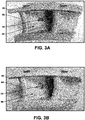
- FIGS. 3A-3J are photographs illustrating an example nozzle guide vane during various stages of repair of a damaged vane airfoil.
- the airfoil 64 of nozzle guide vane 62 suffered burn through damage 66 on the pressure side 68 of the airfoil 64.
- FIG. 3B shows nozzle guide vane 62 after removing a portion of airfoil 64 adjacent to the burn through damage 66 to define a 3/8 inch diameter through-hole 70.
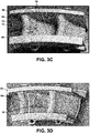
- FIG. 3C shows the airfoil with a BSP material 72 placed in through-hole 70. As shown in FIG. 3C , additional cracks 74 are present in the airfoil adjacent to the repair portion through-hole.
- FIG. 3A shows the airfoil 64 of nozzle guide vane 62 suffered burn through damage 66 on the pressure side 68 of the airfoil 64.
- FIG. 3B shows nozzle guide vane 62 after removing a portion of airfoil 64 adjacent to the burn through damage 66 to define a 3
- FIG. 3D shows additional braze material in the form of braze paste 76 applied to the airfoil 64, including within additional cracks 74, with braze stop-off material on the airfoil 64 to maintain the braze paste 76 in desired locations.
- the braze stop-off material also may be applied inside airfoil 64, which is not shown in the figures.
- FIG. 3E shows the airfoil 64 after a first brazing cycle has been completed to join the BSP material 72 and braze paste 76 to the vane airfoil 64, to repair through-hole and additional cracks 74 and to change BSP material 72 and braze paste 76 into a brazed microstructure.
- FIG. 3F shows two additional BSP materials 78 and 80 placed over the repair portion.
- Each BSP material 78 and 80 in FIG. 3F was about 0.010 inch thick.
- the additional BSP materials 78 and 80 were resistance tack welded to the surface of the vane airfoil 64.
- FIG. 3G shows the vane airfoil 64 after a second brazing cycle to join the additional BSP materials 78 and 80 to the vane airfoil 64.
- FIG. 3H shows the locations of the two sections shown in FIGS. 3I (section 1) and 3J (section 2). As shown in FIGS. 3I and 3J , the BSP filled substantially the entire depth of the repair portion through-hole 70 and additional cracks 74.
- FIGS. 4A-4D are photographs illustrating an example nozzle guide vane 92 during various stages of repair of a damaged platform 94.
- FIG. 4A shows platform burn-through damage 96.
- FIG. 4B shows the platform 94 after removing a portion of the platform 94 adjacent to the damage 96 to define a through-hole 98.
- FIG. 4C shows the platform 94 with a BSP material 100 placed in the through-hole 98 and resistance tack welded in place.
- FIG. 4D shows additional BSP material 102 place on a surface of the platform over the BSP material 100 in the through-hole 98, after heating to join the BSP material 100 to the platform 94.
- FIGS. 5A and 5B are photographs illustrating an example BSP material 114 having three-dimensional surface features 116 and a repaired vane airfoil including the BSP material 114 having the three-dimensional surface features 116.
Landscapes
- Engineering & Computer Science (AREA)
- Mechanical Engineering (AREA)
- Chemical & Material Sciences (AREA)
- General Engineering & Computer Science (AREA)
- Materials Engineering (AREA)
- Physics & Mathematics (AREA)
- Thermal Sciences (AREA)
- Crystallography & Structural Chemistry (AREA)
- Metallurgy (AREA)
- Organic Chemistry (AREA)
- Powder Metallurgy (AREA)
- Turbine Rotor Nozzle Sealing (AREA)
Applications Claiming Priority (1)
| Application Number | Priority Date | Filing Date | Title |
|---|---|---|---|
| US16/272,664 US11305363B2 (en) | 2019-02-11 | 2019-02-11 | Repair of through-hole damage using braze sintered preform |
Publications (1)
| Publication Number | Publication Date |
|---|---|
| EP3693115A1 true EP3693115A1 (fr) | 2020-08-12 |
Family
ID=69411342
Family Applications (1)
| Application Number | Title | Priority Date | Filing Date |
|---|---|---|---|
| EP20154640.5A Pending EP3693115A1 (fr) | 2019-02-11 | 2020-01-30 | Réparation des dommages causés par des trous traversants à l'aide d'une préforme frittée par brasage |
Country Status (4)
| Country | Link |
|---|---|
| US (2) | US11305363B2 (fr) |
| EP (1) | EP3693115A1 (fr) |
| CA (1) | CA3072139A1 (fr) |
| SG (1) | SG10202001061UA (fr) |
Families Citing this family (8)
| Publication number | Priority date | Publication date | Assignee | Title |
|---|---|---|---|---|
| US11090771B2 (en) | 2018-11-05 | 2021-08-17 | Rolls-Royce Corporation | Dual-walled components for a gas turbine engine |
| US11305363B2 (en) * | 2019-02-11 | 2022-04-19 | Rolls-Royce Corporation | Repair of through-hole damage using braze sintered preform |
| JP7386968B2 (ja) * | 2019-07-30 | 2023-11-27 | シーメンス エナジー インコーポレイテッド | 高温ガスタービン部品を修復するためのシステム及び方法 |
| US11795832B2 (en) * | 2019-11-13 | 2023-10-24 | Siemens Energy, Inc. | System and method for repairing high-temperature gas turbine components |
| US11426822B2 (en) * | 2020-12-03 | 2022-08-30 | General Electric Company | Braze composition and process of using |
| US11692446B2 (en) | 2021-09-23 | 2023-07-04 | Rolls-Royce North American Technologies, Inc. | Airfoil with sintered powder components |
| US11524350B1 (en) | 2021-10-04 | 2022-12-13 | General Electric Company | Backwall strike braze repair |
| CN115041915B (zh) * | 2022-06-27 | 2024-02-06 | 广东鸿图科技股份有限公司 | 一种金属3d打印模具的修复方法及服务器 |
Citations (6)
| Publication number | Priority date | Publication date | Assignee | Title |
|---|---|---|---|---|
| EP0973954A1 (fr) * | 1997-04-08 | 2000-01-26 | Allison Engine Company, Inc. | Composition a base de cobalt et technique de reparation par brasage par diffusion d'articles en superalliage |
| EP2078579A1 (fr) * | 2008-01-10 | 2009-07-15 | Siemens Aktiengesellschaft | Procédé de soudage d'un composant et composant doté d'emplacements de soudure et de brasure |
| US20100059573A1 (en) * | 2008-09-08 | 2010-03-11 | General Electric Company | Process of filling openings in a component |
| EP2969378A1 (fr) * | 2013-03-15 | 2016-01-20 | Siemens Energy, Inc. | Préforme préfrittée pour la réparation de composant de superalliage |
| DE102014226055A1 (de) * | 2014-12-16 | 2016-06-16 | Siemens Aktiengesellschaft | Verfahren zum Ausbessern einer Beschädigung an einer Turbinenschaufel |
| EP3095550A1 (fr) * | 2015-05-20 | 2016-11-23 | Rolls-Royce Corporation | Préforme de brasure pré-frittée pour jonction de pièces coulées d'alliage |
Family Cites Families (123)
| Publication number | Priority date | Publication date | Assignee | Title |
|---|---|---|---|---|
| US3067508A (en) * | 1959-07-23 | 1962-12-11 | Int Nickel Co | Method of forming brazed structures |
| US3390986A (en) | 1966-08-30 | 1968-07-02 | Carrier Corp | Method of making a brazing preform |
| DE2527498A1 (de) | 1975-06-20 | 1976-12-30 | Daimler Benz Ag | Radialturbinenrad fuer eine gasturbine |
| US4209348A (en) | 1976-11-17 | 1980-06-24 | United Technologies Corporation | Heat treated superalloy single crystal article and process |
| JPS55161902A (en) | 1979-06-01 | 1980-12-16 | Nissan Motor Co Ltd | Ceramic turbine rotor |
| US4325994A (en) * | 1979-12-29 | 1982-04-20 | Ebara Corporation | Coating metal for preventing the crevice corrosion of austenitic stainless steel and method of preventing crevice corrosion using such metal |
| FR2511908A1 (fr) | 1981-08-26 | 1983-03-04 | Snecma | Procede de brasage-diffusion destine aux pieces en superalliages |
| EP0123702B1 (fr) | 1983-04-27 | 1987-09-23 | BBC Aktiengesellschaft Brown, Boveri & Cie. | Procédé de liaison de pièces métalliques |
| US5017753A (en) | 1986-10-17 | 1991-05-21 | Board Of Regents, The University Of Texas System | Method and apparatus for producing parts by selective sintering |
| DE68908980T2 (de) | 1988-07-14 | 1994-01-20 | Rolls Royce Plc | Legierung und Verfahren zu ihrer Verwendung. |
| US5395584A (en) | 1992-06-17 | 1995-03-07 | Avco Corporation | Nickel-base superalloy compositions |
| US5474227A (en) | 1993-06-24 | 1995-12-12 | The Idod Trust | Method of forming seamed metal tube |
| US5332360A (en) | 1993-09-08 | 1994-07-26 | General Electric Company | Stator vane having reinforced braze joint |
| US5381944A (en) | 1993-11-04 | 1995-01-17 | The Regents Of The University Of California | Low temperature reactive bonding |
| JPH10505538A (ja) | 1994-08-25 | 1998-06-02 | キューキューシー,インコーポレイテッド | ナノ規模の粒子およびその用途 |
| JPH09168927A (ja) | 1995-12-19 | 1997-06-30 | Hitachi Ltd | ガスタービン用動翼,静翼の補修方法 |
| US5902421A (en) * | 1996-04-09 | 1999-05-11 | General Electric Co. | Nickel-base braze material |
| US5732468A (en) | 1996-12-05 | 1998-03-31 | General Electric Company | Method for bonding a turbine engine vane segment |
| US5797725A (en) | 1997-05-23 | 1998-08-25 | Allison Advanced Development Company | Gas turbine engine vane and method of manufacture |
| US6003754A (en) | 1997-10-21 | 1999-12-21 | Allison Advanced Development Co. | Airfoil for a gas turbine engine and method of manufacture |
| US6325871B1 (en) | 1997-10-27 | 2001-12-04 | Siemens Westinghouse Power Corporation | Method of bonding cast superalloys |
| US6172327B1 (en) | 1998-07-14 | 2001-01-09 | General Electric Company | Method for laser twist welding of compressor blisk airfoils |
| US6214248B1 (en) | 1998-11-12 | 2001-04-10 | General Electric Company | Method of forming hollow channels within a component |
| US6464128B1 (en) | 1999-05-28 | 2002-10-15 | General Electric Company | Braze repair of a gas turbine engine stationary shroud |
| US6213714B1 (en) | 1999-06-29 | 2001-04-10 | Allison Advanced Development Company | Cooled airfoil |
| US6199746B1 (en) | 1999-08-02 | 2001-03-13 | General Electric Company | Method for preparing superalloy castings using a metallurgically bonded tapered plug |
| US6454885B1 (en) | 2000-12-15 | 2002-09-24 | Rolls-Royce Corporation | Nickel diffusion braze alloy and method for repair of superalloys |
| US6579061B1 (en) | 2001-07-27 | 2003-06-17 | General Electric Company | Selective step turbine nozzle |
| US6602053B2 (en) | 2001-08-02 | 2003-08-05 | Siemens Westinghouse Power Corporation | Cooling structure and method of manufacturing the same |
| US6575702B2 (en) | 2001-10-22 | 2003-06-10 | General Electric Company | Airfoils with improved strength and manufacture and repair thereof |
| US6789315B2 (en) * | 2002-03-21 | 2004-09-14 | General Electric Company | Establishing a throat area of a gas turbine nozzle, and a technique for modifying the nozzle vanes |
| US6837417B2 (en) | 2002-09-19 | 2005-01-04 | Siemens Westinghouse Power Corporation | Method of sealing a hollow cast member |
| US20040086635A1 (en) | 2002-10-30 | 2004-05-06 | Grossklaus Warren Davis | Method of repairing a stationary shroud of a gas turbine engine using laser cladding |
| US6797914B2 (en) | 2003-02-05 | 2004-09-28 | General Motors Corporation | Joining workpieces by laser welding with powder injection |
| US7080971B2 (en) | 2003-03-12 | 2006-07-25 | Florida Turbine Technologies, Inc. | Cooled turbine spar shell blade construction |
| US7146725B2 (en) | 2003-05-06 | 2006-12-12 | Siemens Power Generation, Inc. | Repair of combustion turbine components |
| US7051435B1 (en) | 2003-06-13 | 2006-05-30 | General Electric Company | Process for repairing turbine components |
| US7419086B2 (en) * | 2003-07-14 | 2008-09-02 | Honeywell International Inc. | Low cost brazes for titanium |
| US7146815B2 (en) | 2003-07-31 | 2006-12-12 | United Technologies Corporation | Combustor |
| US20050067061A1 (en) | 2003-09-26 | 2005-03-31 | General Electric Company | Nickel-based braze alloy compositions and related processes and articles |
| US7363763B2 (en) | 2003-10-23 | 2008-04-29 | United Technologies Corporation | Combustor |
| US7343676B2 (en) | 2004-01-29 | 2008-03-18 | United Technologies Corporation | Method of restoring dimensions of an airfoil and preform for performing same |
| US6951112B2 (en) | 2004-02-10 | 2005-10-04 | General Electric Company | Methods and apparatus for assembling gas turbine engines |
| US20050217110A1 (en) | 2004-04-06 | 2005-10-06 | Topal Valeriy I | Deposition repair of hollow items |
| US20050235492A1 (en) | 2004-04-22 | 2005-10-27 | Arness Brian P | Turbine airfoil trailing edge repair and methods therefor |
| US7335427B2 (en) | 2004-12-17 | 2008-02-26 | General Electric Company | Preform and method of repairing nickel-base superalloys and components repaired thereby |
| US7966707B2 (en) | 2005-05-06 | 2011-06-28 | United Technologies Corporation | Method for repairing superalloy components using inserts |
| US20070044306A1 (en) | 2005-08-29 | 2007-03-01 | United Technologies Corporation | Superalloy repair methods |
| US7761989B2 (en) | 2005-11-22 | 2010-07-27 | United Technologies Corporation | Methods for repairing gas turbine engine components |
| US7575213B2 (en) * | 2005-12-16 | 2009-08-18 | Rausch Matthew S | Article and method for hanging items from I-joist beams |
| US8703044B2 (en) | 2006-01-03 | 2014-04-22 | General Electric Company | Machine components and methods of fabricating and repairing |
| US7731809B2 (en) | 2006-01-18 | 2010-06-08 | Honeywell International Inc. | Activated diffusion brazing alloys and repair process |
| US7653994B2 (en) | 2006-03-22 | 2010-02-02 | General Electric Company | Repair of HPT shrouds with sintered preforms |
| US7845549B2 (en) | 2006-05-31 | 2010-12-07 | General Electric Company | MIM braze preforms |
| US20080087710A1 (en) | 2006-06-06 | 2008-04-17 | The Regents Of The University Of California | RAPID, REDUCED TEMPERATURE JOINING OF ALUMINA CERAMICS WITH Ni/Nb/Ni INTERLAYERS |
| DE102006026704A1 (de) | 2006-06-08 | 2007-12-13 | Mtu Aero Engines Gmbh | Verfahren zur Herstellung oder Reparatur von Turbinen- oder Triebwerksbauteilen, sowie Bauteil, nämlich Turbinen- oder Triebwerksbauteil |
| US20080011813A1 (en) | 2006-07-17 | 2008-01-17 | David Vincent Bucci | Repair process for coated articles |
| US20100257733A1 (en) | 2006-07-20 | 2010-10-14 | Honeywell International, Inc. | High pressure single crystal turbine blade tip repair with laser cladding |
| US20100236067A1 (en) | 2006-08-01 | 2010-09-23 | Honeywell International, Inc. | Hybrid welding repair of gas turbine superalloy components |
| DE102006049219A1 (de) | 2006-10-18 | 2008-04-30 | Mtu Aero Engines Gmbh | Hochdruckturbinen-Schaufel und Verfahren zur Reparatur von Hochdruckturbinen-Schaufeln |
| US20110180199A1 (en) | 2007-04-17 | 2011-07-28 | United Technologies Corporation | Powder -metallurgy braze preform and method of use |
| US7975902B2 (en) | 2007-04-30 | 2011-07-12 | Airbus Operations Gmbh | Joining method for joining components |
| US20090026182A1 (en) | 2007-07-27 | 2009-01-29 | Honeywell International, Inc. | In-situ brazing methods for repairing gas turbine engine components |
| US20090041611A1 (en) * | 2007-08-07 | 2009-02-12 | General Electric Company | Braze alloy composition with enhanced oxidation resistance and methods of using the same |
| JP5078537B2 (ja) | 2007-10-15 | 2012-11-21 | 三菱重工業株式会社 | 補修方法 |
| US8356409B2 (en) | 2007-11-01 | 2013-01-22 | United Technologies Corporation | Repair method for gas turbine engine components |
| US20090255118A1 (en) | 2008-04-11 | 2009-10-15 | General Electric Company | Method of manufacturing mixers |
| US8539659B2 (en) | 2008-04-23 | 2013-09-24 | United Technologies Corporation | Method of repairing an article |
| GB0816255D0 (en) | 2008-09-08 | 2008-10-15 | Rolls Royce Plc | A method of repairing an aluminide coating on an article |
| DE102009004661A1 (de) | 2009-01-12 | 2010-07-15 | Rolls-Royce Deutschland Ltd & Co Kg | Vorrichtung zur Reparatur der Schaufeln von BLISK-Trommeln mittels Laserstrahlauftragsschweißen |
| US8070450B1 (en) | 2009-04-20 | 2011-12-06 | Florida Turbine Technologies, Inc. | High temperature turbine rotor blade |
| GB0913887D0 (en) | 2009-08-10 | 2009-09-16 | A method of joining components | |
| US20110185739A1 (en) | 2010-01-29 | 2011-08-04 | Honeywell International Inc. | Gas turbine combustors with dual walled liners |
| EP2353763A1 (fr) | 2010-02-10 | 2011-08-10 | Siemens Aktiengesellschaft | Procédé de fabrication de composant pour gaz chaud avec un canal de refroidissement par brasage d'un élément fritté sur une base ; composant à gaz chaud correspondant |
| US8449249B2 (en) | 2010-04-09 | 2013-05-28 | Williams International Co., L.L.C. | Turbine nozzle apparatus and associated method of manufacture |
| US8590158B2 (en) | 2010-10-29 | 2013-11-26 | Corning Incorporated | Methods of making filter apparatus and fabricating a porous ceramic article |
| US8739404B2 (en) | 2010-11-23 | 2014-06-03 | General Electric Company | Turbine components with cooling features and methods of manufacturing the same |
| US10060264B2 (en) | 2010-12-30 | 2018-08-28 | Rolls-Royce North American Technologies Inc. | Gas turbine engine and cooled flowpath component therefor |
| US9085980B2 (en) | 2011-03-04 | 2015-07-21 | Honeywell International Inc. | Methods for repairing turbine components |
| US20120231295A1 (en) | 2011-03-08 | 2012-09-13 | General Electric Company | Method of fabricating a component and a component |
| WO2012122487A1 (fr) | 2011-03-09 | 2012-09-13 | Rolls-Royce Corporation | Système d'inspection reposant sur un protocole |
| US8528208B2 (en) | 2011-04-11 | 2013-09-10 | General Electric Company | Methods of fabricating a coated component using multiple types of fillers |
| US20130086784A1 (en) | 2011-10-06 | 2013-04-11 | General Electric Company | Repair methods for cooled components |
| US20130086785A1 (en) * | 2011-10-06 | 2013-04-11 | Yan Cui | Hybrid repair plugs and repair methods incorporating the same |
| US10076811B2 (en) | 2011-11-03 | 2018-09-18 | Siemens Energy, Inc. | Structural braze repair of superalloy component |
| US8808870B2 (en) * | 2011-11-28 | 2014-08-19 | Kennametal Inc. | Functionally graded coating |
| US9810069B2 (en) | 2012-07-02 | 2017-11-07 | Ansaldo Energia Switzerland AG | Repair of a shrouded blade |
| EP2713007A1 (fr) | 2012-10-01 | 2014-04-02 | Siemens Aktiengesellschaft | Réparation de bords d'un composant à l'aide d'éléments PSP et composant |
| US9863249B2 (en) | 2012-12-04 | 2018-01-09 | Siemens Energy, Inc. | Pre-sintered preform repair of turbine blades |
| US9003657B2 (en) | 2012-12-18 | 2015-04-14 | General Electric Company | Components with porous metal cooling and methods of manufacture |
| US10315264B2 (en) | 2013-01-29 | 2019-06-11 | General Electric Company | Joining process and joined article |
| US20140260327A1 (en) | 2013-02-26 | 2014-09-18 | General Electric Company | Cooled article |
| US9174312B2 (en) | 2013-03-12 | 2015-11-03 | Honeywell International Inc. | Methods for the repair of gas turbine engine components using additive manufacturing techniques |
| WO2014149094A1 (fr) | 2013-03-15 | 2014-09-25 | Xu Raymond R | Matériaux de brasage et procédé de jonction de composites à matrice céramique |
| US20140302278A1 (en) | 2013-04-09 | 2014-10-09 | General Electric Company | Components with double sided cooling features and methods of manufacture |
| US9394796B2 (en) | 2013-07-12 | 2016-07-19 | General Electric Company | Turbine component and methods of assembling the same |
| US10525525B2 (en) | 2013-07-19 | 2020-01-07 | United Technologies Corporation | Additively manufactured core |
| US9126279B2 (en) | 2013-09-30 | 2015-09-08 | General Electric Company | Brazing method |
| US9476306B2 (en) | 2013-11-26 | 2016-10-25 | General Electric Company | Components with multi-layered cooling features and methods of manufacture |
| WO2015147929A2 (fr) | 2013-12-20 | 2015-10-01 | United Technologies Corporation | Refroidissement d'un corps à ouverture d'une paroi de chambre de combustion |
| US20150224607A1 (en) | 2014-02-07 | 2015-08-13 | Siemens Energy, Inc. | Superalloy solid freeform fabrication and repair with preforms of metal and flux |
| CN105091030A (zh) | 2014-05-23 | 2015-11-25 | 中航商用航空发动机有限责任公司 | 用于火焰筒的套筒以及火焰筒 |
| CA2893299C (fr) | 2014-06-02 | 2017-11-14 | Rolls-Royce Corporation | Accessoire de jointage haute temperature |
| US9434017B2 (en) * | 2014-06-30 | 2016-09-06 | General Electric Company | Braze methods and components with heat resistant materials |
| US10478920B2 (en) | 2014-09-29 | 2019-11-19 | Rolls-Royce Corporation | Dual wall components for gas turbine engines |
| EP3034799B1 (fr) | 2014-12-19 | 2018-02-07 | Ansaldo Energia IP UK Limited | Élément d'aubage pour une machine d'écoulement de fluide |
| US10655482B2 (en) | 2015-02-05 | 2020-05-19 | Rolls-Royce Corporation | Vane assemblies for gas turbine engines |
| US20160230993A1 (en) | 2015-02-10 | 2016-08-11 | United Technologies Corporation | Combustor liner effusion cooling holes |
| EP3061557B1 (fr) | 2015-02-26 | 2018-04-18 | Rolls-Royce Corporation | Réparation de composants métalliques à paroi double au moyen d'un apport de matériau de dépôt à énergie dirigée |
| US10766105B2 (en) | 2015-02-26 | 2020-09-08 | Rolls-Royce Corporation | Repair of dual walled metallic components using braze material |
| US9850760B2 (en) | 2015-04-15 | 2017-12-26 | Honeywell International Inc. | Directed cooling for rotating machinery |
| US20160375461A1 (en) | 2015-06-24 | 2016-12-29 | Rolls-Royce Corporation | Automated coating application |
| US10520193B2 (en) | 2015-10-28 | 2019-12-31 | General Electric Company | Cooling patch for hot gas path components |
| US9657580B1 (en) | 2016-03-07 | 2017-05-23 | General Electric Company | Brazing tape and method of forming microchannels in a thermal barrier coating |
| US20170306775A1 (en) | 2016-04-21 | 2017-10-26 | General Electric Company | Article, component, and method of making a component |
| US10180250B2 (en) | 2016-07-27 | 2019-01-15 | Whirlpool Corporation | User interface for a household appliance |
| US20180073390A1 (en) | 2016-09-13 | 2018-03-15 | Rolls-Royce Corporation | Additively deposited gas turbine engine cooling component |
| US10519780B2 (en) | 2016-09-13 | 2019-12-31 | Rolls-Royce Corporation | Dual-walled components for a gas turbine engine |
| US10265806B2 (en) | 2016-10-04 | 2019-04-23 | General Electric Company | System and method for sealing internal channels defined in a component |
| US10828732B2 (en) | 2017-04-27 | 2020-11-10 | General Electric Company | Treated turbine diaphragm and method for treating a turbine diaphragm |
| US10884392B2 (en) | 2018-08-23 | 2021-01-05 | Autodesk, Inc. | Assessing deflections experienced by a workpiece during computer controlled machining with a toolpath to determine stock amount |
| US11090771B2 (en) | 2018-11-05 | 2021-08-17 | Rolls-Royce Corporation | Dual-walled components for a gas turbine engine |
| US11305363B2 (en) * | 2019-02-11 | 2022-04-19 | Rolls-Royce Corporation | Repair of through-hole damage using braze sintered preform |
-
2019
- 2019-02-11 US US16/272,664 patent/US11305363B2/en active Active
-
2020
- 2020-01-30 EP EP20154640.5A patent/EP3693115A1/fr active Pending
- 2020-02-06 SG SG10202001061UA patent/SG10202001061UA/en unknown
- 2020-02-11 CA CA3072139A patent/CA3072139A1/fr active Pending
-
2022
- 2022-04-15 US US17/659,397 patent/US11731206B2/en active Active
Patent Citations (6)
| Publication number | Priority date | Publication date | Assignee | Title |
|---|---|---|---|---|
| EP0973954A1 (fr) * | 1997-04-08 | 2000-01-26 | Allison Engine Company, Inc. | Composition a base de cobalt et technique de reparation par brasage par diffusion d'articles en superalliage |
| EP2078579A1 (fr) * | 2008-01-10 | 2009-07-15 | Siemens Aktiengesellschaft | Procédé de soudage d'un composant et composant doté d'emplacements de soudure et de brasure |
| US20100059573A1 (en) * | 2008-09-08 | 2010-03-11 | General Electric Company | Process of filling openings in a component |
| EP2969378A1 (fr) * | 2013-03-15 | 2016-01-20 | Siemens Energy, Inc. | Préforme préfrittée pour la réparation de composant de superalliage |
| DE102014226055A1 (de) * | 2014-12-16 | 2016-06-16 | Siemens Aktiengesellschaft | Verfahren zum Ausbessern einer Beschädigung an einer Turbinenschaufel |
| EP3095550A1 (fr) * | 2015-05-20 | 2016-11-23 | Rolls-Royce Corporation | Préforme de brasure pré-frittée pour jonction de pièces coulées d'alliage |
Also Published As
| Publication number | Publication date |
|---|---|
| US20220241881A1 (en) | 2022-08-04 |
| SG10202001061UA (en) | 2020-09-29 |
| US11305363B2 (en) | 2022-04-19 |
| US20200254548A1 (en) | 2020-08-13 |
| US11731206B2 (en) | 2023-08-22 |
| CA3072139A1 (fr) | 2020-08-11 |
Similar Documents
| Publication | Publication Date | Title |
|---|---|---|
| US11731206B2 (en) | Repair of through-hole damage using braze sintered preform | |
| US10875128B2 (en) | Pre-sintered preform braze for joining alloy castings | |
| US7335427B2 (en) | Preform and method of repairing nickel-base superalloys and components repaired thereby | |
| US8087565B2 (en) | Process of filling openings in a component | |
| US5902421A (en) | Nickel-base braze material | |
| US4614296A (en) | Diffusion brazing process for pieces of superalloys | |
| CN105149597B (zh) | 金属或合金部件的修复或联结方法和经修复或联结的部件 | |
| EP2902516B1 (fr) | Produit d'apport de soudure pour superalliages à base de nickel | |
| RU2763528C1 (ru) | Замена секции турбинного аэродинамического профиля с металлической предварительно спеченной заготовкой для пайки | |
| EP0836904A2 (fr) | Méthode de réparation d'éléments en alliage métallique, tels que des éléments d'un turbomoteur | |
| EP2868426B1 (fr) | Compositions d'alliage de brasage et procédés de brasage pour super-alliages | |
| EP1371439A1 (fr) | Méthode de réparation par soudage d'un composant à l'aide d'un matériau métallique réfractaire | |
| US20130086785A1 (en) | Hybrid repair plugs and repair methods incorporating the same | |
| US20030136811A1 (en) | Liquid phase diffusion bonding to a superalloy component | |
| US7533795B2 (en) | Welding process | |
| EP3345718B1 (fr) | Structure de réparation de brasure de composants en superalliage difficiles à souder à l'aide d'insert d'alliage par diffusion | |
| EP3034229A1 (fr) | Produit d'apport pour superalliages | |
| AL-Nafeay et al. | Overview of joining and repairing techniques of ni-based superalloy for industrial gas turbine applications | |
| JP5138149B2 (ja) | 表面酸化物溶接溶込み強化方法及び物品 | |
| CN108998698B (zh) | 超合金制品、部件及其处理方法 | |
| US20210205909A1 (en) | Pre-sintered preform braze reinforcement of pressure vessels | |
| Sparling et al. | Liburdi Power Metallurgy: New Compositions for High Strength Repairs of Turbine Components |
Legal Events
| Date | Code | Title | Description |
|---|---|---|---|
| PUAI | Public reference made under article 153(3) epc to a published international application that has entered the european phase |
Free format text: ORIGINAL CODE: 0009012 |
|
| STAA | Information on the status of an ep patent application or granted ep patent |
Free format text: STATUS: THE APPLICATION HAS BEEN PUBLISHED |
|
| AK | Designated contracting states |
Kind code of ref document: A1 Designated state(s): AL AT BE BG CH CY CZ DE DK EE ES FI FR GB GR HR HU IE IS IT LI LT LU LV MC MK MT NL NO PL PT RO RS SE SI SK SM TR |
|
| AX | Request for extension of the european patent |
Extension state: BA ME |
|
| STAA | Information on the status of an ep patent application or granted ep patent |
Free format text: STATUS: REQUEST FOR EXAMINATION WAS MADE |
|
| 17P | Request for examination filed |
Effective date: 20210203 |
|
| RBV | Designated contracting states (corrected) |
Designated state(s): AL AT BE BG CH CY CZ DE DK EE ES FI FR GB GR HR HU IE IS IT LI LT LU LV MC MK MT NL NO PL PT RO RS SE SI SK SM TR |
|
| STAA | Information on the status of an ep patent application or granted ep patent |
Free format text: STATUS: EXAMINATION IS IN PROGRESS |
|
| 17Q | First examination report despatched |
Effective date: 20230301 |
|
| RIC1 | Information provided on ipc code assigned before grant |
Ipc: B23K 101/00 20060101ALN20231013BHEP Ipc: C21D 9/50 20060101ALI20231013BHEP Ipc: F01D 5/00 20060101ALI20231013BHEP Ipc: B23P 6/04 20060101ALI20231013BHEP Ipc: B23P 6/00 20060101ALI20231013BHEP Ipc: B23K 35/30 20060101ALI20231013BHEP Ipc: B23K 35/02 20060101ALI20231013BHEP Ipc: B23K 1/008 20060101ALI20231013BHEP Ipc: B23K 1/00 20060101AFI20231013BHEP |
|
| RIC1 | Information provided on ipc code assigned before grant |
Ipc: B23K 101/00 20060101ALN20231023BHEP Ipc: C21D 9/50 20060101ALI20231023BHEP Ipc: F01D 5/00 20060101ALI20231023BHEP Ipc: B23P 6/04 20060101ALI20231023BHEP Ipc: B23P 6/00 20060101ALI20231023BHEP Ipc: B23K 35/30 20060101ALI20231023BHEP Ipc: B23K 35/02 20060101ALI20231023BHEP Ipc: B23K 1/008 20060101ALI20231023BHEP Ipc: B23K 1/00 20060101AFI20231023BHEP |
|
| GRAP | Despatch of communication of intention to grant a patent |
Free format text: ORIGINAL CODE: EPIDOSNIGR1 |
|
| RIC1 | Information provided on ipc code assigned before grant |
Ipc: B23K 101/00 20060101ALN20231115BHEP Ipc: C21D 9/50 20060101ALI20231115BHEP Ipc: F01D 5/00 20060101ALI20231115BHEP Ipc: B23P 6/04 20060101ALI20231115BHEP Ipc: B23P 6/00 20060101ALI20231115BHEP Ipc: B23K 35/30 20060101ALI20231115BHEP Ipc: B23K 35/02 20060101ALI20231115BHEP Ipc: B23K 1/008 20060101ALI20231115BHEP Ipc: B23K 1/00 20060101AFI20231115BHEP |
|
| STAA | Information on the status of an ep patent application or granted ep patent |
Free format text: STATUS: GRANT OF PATENT IS INTENDED |
|
| INTG | Intention to grant announced |
Effective date: 20231221 |
|
| GRAJ | Information related to disapproval of communication of intention to grant by the applicant or resumption of examination proceedings by the epo deleted |
Free format text: ORIGINAL CODE: EPIDOSDIGR1 |
|
| STAA | Information on the status of an ep patent application or granted ep patent |
Free format text: STATUS: EXAMINATION IS IN PROGRESS |
|
| GRAP | Despatch of communication of intention to grant a patent |
Free format text: ORIGINAL CODE: EPIDOSNIGR1 |
|
| STAA | Information on the status of an ep patent application or granted ep patent |
Free format text: STATUS: GRANT OF PATENT IS INTENDED |
|
| INTC | Intention to grant announced (deleted) |