EP3693087B1 - Verbesserte zielzellkonzentration mittels dielektrophorese (dep) - Google Patents
Verbesserte zielzellkonzentration mittels dielektrophorese (dep) Download PDFInfo
- Publication number
- EP3693087B1 EP3693087B1 EP20167555.0A EP20167555A EP3693087B1 EP 3693087 B1 EP3693087 B1 EP 3693087B1 EP 20167555 A EP20167555 A EP 20167555A EP 3693087 B1 EP3693087 B1 EP 3693087B1
- Authority
- EP
- European Patent Office
- Prior art keywords
- area
- sample
- capture area
- electrodes
- capture
- Prior art date
- Legal status (The legal status is an assumption and is not a legal conclusion. Google has not performed a legal analysis and makes no representation as to the accuracy of the status listed.)
- Active
Links
Images


Classifications
-
- B—PERFORMING OPERATIONS; TRANSPORTING
- B01—PHYSICAL OR CHEMICAL PROCESSES OR APPARATUS IN GENERAL
- B01L—CHEMICAL OR PHYSICAL LABORATORY APPARATUS FOR GENERAL USE
- B01L3/00—Containers or dishes for laboratory use, e.g. laboratory glassware; Droppers
- B01L3/50—Containers for the purpose of retaining a material to be analysed, e.g. test tubes
- B01L3/502—Containers for the purpose of retaining a material to be analysed, e.g. test tubes with fluid transport, e.g. in multi-compartment structures
- B01L3/5027—Containers for the purpose of retaining a material to be analysed, e.g. test tubes with fluid transport, e.g. in multi-compartment structures by integrated microfluidic structures, i.e. dimensions of channels and chambers are such that surface tension forces are important, e.g. lab-on-a-chip
- B01L3/502761—Containers for the purpose of retaining a material to be analysed, e.g. test tubes with fluid transport, e.g. in multi-compartment structures by integrated microfluidic structures, i.e. dimensions of channels and chambers are such that surface tension forces are important, e.g. lab-on-a-chip specially adapted for handling suspended solids or molecules independently from the bulk fluid flow, e.g. for trapping or sorting beads or physically stretching molecules
-
- G—PHYSICS
- G01—MEASURING; TESTING
- G01N—INVESTIGATING OR ANALYSING MATERIALS BY DETERMINING THEIR CHEMICAL OR PHYSICAL PROPERTIES
- G01N1/00—Sampling; Preparing specimens for investigation
- G01N1/28—Preparing specimens for investigation including physical details of (bio-)chemical methods covered elsewhere, e.g. G01N33/50, C12Q
- G01N1/40—Concentrating samples
-
- G—PHYSICS
- G01—MEASURING; TESTING
- G01N—INVESTIGATING OR ANALYSING MATERIALS BY DETERMINING THEIR CHEMICAL OR PHYSICAL PROPERTIES
- G01N33/00—Investigating or analysing materials by specific methods not covered by groups G01N1/00 - G01N31/00
- G01N33/48—Biological material, e.g. blood, urine; Haemocytometers
- G01N33/50—Chemical analysis of biological material, e.g. blood, urine; Testing involving biospecific ligand binding methods; Immunological testing
- G01N33/53—Immunoassay; Biospecific binding assay; Materials therefor
- G01N33/569—Immunoassay; Biospecific binding assay; Materials therefor for microorganisms, e.g. protozoa, bacteria, viruses
- G01N33/56966—Animal cells
-
- B—PERFORMING OPERATIONS; TRANSPORTING
- B01—PHYSICAL OR CHEMICAL PROCESSES OR APPARATUS IN GENERAL
- B01L—CHEMICAL OR PHYSICAL LABORATORY APPARATUS FOR GENERAL USE
- B01L2200/00—Solutions for specific problems relating to chemical or physical laboratory apparatus
- B01L2200/06—Fluid handling related problems
- B01L2200/0631—Purification arrangements, e.g. solid phase extraction [SPE]
-
- B—PERFORMING OPERATIONS; TRANSPORTING
- B01—PHYSICAL OR CHEMICAL PROCESSES OR APPARATUS IN GENERAL
- B01L—CHEMICAL OR PHYSICAL LABORATORY APPARATUS FOR GENERAL USE
- B01L2200/00—Solutions for specific problems relating to chemical or physical laboratory apparatus
- B01L2200/06—Fluid handling related problems
- B01L2200/0647—Handling flowable solids, e.g. microscopic beads, cells, particles
- B01L2200/0668—Trapping microscopic beads
-
- B—PERFORMING OPERATIONS; TRANSPORTING
- B01—PHYSICAL OR CHEMICAL PROCESSES OR APPARATUS IN GENERAL
- B01L—CHEMICAL OR PHYSICAL LABORATORY APPARATUS FOR GENERAL USE
- B01L2300/00—Additional constructional details
- B01L2300/06—Auxiliary integrated devices, integrated components
- B01L2300/0627—Sensor or part of a sensor is integrated
- B01L2300/0645—Electrodes
-
- B—PERFORMING OPERATIONS; TRANSPORTING
- B01—PHYSICAL OR CHEMICAL PROCESSES OR APPARATUS IN GENERAL
- B01L—CHEMICAL OR PHYSICAL LABORATORY APPARATUS FOR GENERAL USE
- B01L2300/00—Additional constructional details
- B01L2300/08—Geometry, shape and general structure
- B01L2300/0809—Geometry, shape and general structure rectangular shaped
- B01L2300/0816—Cards, e.g. flat sample carriers usually with flow in two horizontal directions
-
- B—PERFORMING OPERATIONS; TRANSPORTING
- B01—PHYSICAL OR CHEMICAL PROCESSES OR APPARATUS IN GENERAL
- B01L—CHEMICAL OR PHYSICAL LABORATORY APPARATUS FOR GENERAL USE
- B01L2300/00—Additional constructional details
- B01L2300/08—Geometry, shape and general structure
- B01L2300/0861—Configuration of multiple channels and/or chambers in a single devices
- B01L2300/0864—Configuration of multiple channels and/or chambers in a single devices comprising only one inlet and multiple receiving wells, e.g. for separation, splitting
-
- B—PERFORMING OPERATIONS; TRANSPORTING
- B01—PHYSICAL OR CHEMICAL PROCESSES OR APPARATUS IN GENERAL
- B01L—CHEMICAL OR PHYSICAL LABORATORY APPARATUS FOR GENERAL USE
- B01L2300/00—Additional constructional details
- B01L2300/08—Geometry, shape and general structure
- B01L2300/0861—Configuration of multiple channels and/or chambers in a single devices
- B01L2300/0867—Multiple inlets and one sample wells, e.g. mixing, dilution
-
- B—PERFORMING OPERATIONS; TRANSPORTING
- B01—PHYSICAL OR CHEMICAL PROCESSES OR APPARATUS IN GENERAL
- B01L—CHEMICAL OR PHYSICAL LABORATORY APPARATUS FOR GENERAL USE
- B01L2400/00—Moving or stopping fluids
- B01L2400/04—Moving fluids with specific forces or mechanical means
- B01L2400/0403—Moving fluids with specific forces or mechanical means specific forces
- B01L2400/0415—Moving fluids with specific forces or mechanical means specific forces electrical forces, e.g. electrokinetic
- B01L2400/0424—Dielectrophoretic forces
-
- G—PHYSICS
- G01—MEASURING; TESTING
- G01N—INVESTIGATING OR ANALYSING MATERIALS BY DETERMINING THEIR CHEMICAL OR PHYSICAL PROPERTIES
- G01N1/00—Sampling; Preparing specimens for investigation
- G01N1/28—Preparing specimens for investigation including physical details of (bio-)chemical methods covered elsewhere, e.g. G01N33/50, C12Q
- G01N1/40—Concentrating samples
- G01N2001/4038—Concentrating samples electric methods, e.g. electromigration, electrophoresis, ionisation
Definitions
- the present invention relates to methods of and devices for concentrating target cells using dielectrophoresis (DEP).
- DEP dielectrophoresis
- the method allows relatively high throughput of sample (preferably using sample volumes of up to 100ml, or up to 10ml, or up to 1ml) through a microfluidic device in order to allow rapid capture of target cells even when they are present in low concentrations within the sample.
- the method utilises multiple areas or chambers through which samples will flow, the areas or chambers arranged such that the first capture area has a larger area and faster flow rate than a second chamber, the second chamber being positioned downstream of the first capture area and being smaller with a slower flow rate to further concentrate the material captured in the first capture area.
- Tuberculosis causes 2 million deaths per year, despite most cases being curable. With no effective vaccine available, early diagnosis and effective treatment are crucial to eliminating this disease.
- POC point of care
- Dielectrophoresis is where a force is exerted on a dielectric or polarisable particle, causing it to move, when it is subjected to a spatially nonuniform electric field. DEP motion can be induced toward an electrode surface (positive DEP) or away from an electrode surface (negative DEP).
- DEP can be used for microfluidic continuous flow processing of a sample potentially containing target cells to concentrate the target cells.
- a DEP electrode is tuned to selectively trap target cells suspended in a sample stream onto the designated area inside a microfluidic channel, whilst unwanted cells and material continue to be drawn through the microfluidic channel by the flow. This requires target specific DEP forces that are strong enough to continuously trap the cells against the hydrodynamic forces.
- DEP operation is effective for the trapping based cell separation and concentration because the target cells can be captured on the electrode's surfaces and can then be released by turning off the electric field.
- the present invention aims to obviate or mitigate one or more of the drawbacks associated with the prior art.
- a microfluidic device (1, 1', 1" for concentrating target cells, characterised in that the device comprises:
- the first capture area (2, 2', 2") comprises at least one inlet (3, 3', 3"), wherein said at least one inlet (3, 3', 3") is divided into multiple channels (14', 14"), wherein each channel (14', 14") is of smaller circumference than the said at least one inlet (3, 3', 3") of the first capture area (2, 2', 2").
- the device (1, 1', 1") comprises a control module that introduces flow of new buffer or media into the first capture area (2, 2', 2") and/or second area (6, 6', 6") when the electrodes in said first capture area (2, 2', 2") or second area (6, 6', 6") are deactivated.
- the device comprises an optical detection device.
- said optical detection device is arranged to detect signals from the second area (6, 6', 6").
- the waste area is a waste reservoir (9).
- the flow regulators are pumps.
- a method for concentrating target particles in a sample comprising the steps of;
- the step of releasing trapped target particles from the first plurality of electrodes (5, 5', 5") to provide an enriched sample comprises deactivating the electrodes (5, 5', 5") in the first capture area (2, 2', 2") after a defined period of time to release trapped target particles to provide an enriched sample.
- a new buffer or media is flowed into the first capture area (2, 2', 2").
- the sample is low salt or low ionic strength.
- the method includes the further step of deactivating the electrodes (5a, 5a', 5a") in the second area (6, 6', 6") after a period of time to release trapped target cells to provide a further enriched sample.
- a new buffer or media is flowed into the second area (6, 6', 6").
- an optical detection device is provided, and target particles are viewed using the optical detection device.
- said optical detection device is arranged to detect signals from the second area (6, 6', 6").
- the inventors have found that by flowing a sample through a first larger area, such as a chamber, chamber with DEP electrodes at a relatively high flow rate allows an initial quick capture, the captured cells can then be released which can then be followed by flowing the resulting enriched flow through a second smaller chamber at a lower flow rate than in the first capture area.
- This allows target cell to be concentrated efficiently and quickly (particularly as compared to the method of simply flowing through a channel with a DEP electrode).
- this allows a relatively large sample volume to be processed in a time effective manner irrespective of whether there are high or low amounts of target present. Effectively the system allows for sample to flow with a higher mean velocity across the first area than the second area.
- references to an enriched sample or further enriched sample will only include target cells in that case that such cells are present in the original sample i.e. if the sample contains pathogen.
- the first capture area by dividing the first capture area into a plurality of, preferably parallel, smaller circumference channels this allows a relatively large volume of sample to be flowed with the characteristics of smaller volumes.
- the problems often associated with laminar flow characteristics where the center of the flow is typically faster than the edges is lessened.
- problems associated with flow at the edges of the channels are mitigated and there are less issues with voltage drop across the electrodes.
- a microfluidic device 1 (or portion thereof) is generally depicted in figure 1 .
- the device comprises a first capture area 2 in the form of a chamber with a first inlet 3 through which fluid can flow into the first capture area 2, and a first outlet 4 through which fluid can leave the first capture area 2.
- the first capture area comprises a plurality of electrodes 5 arranged such that sample will flow over them or come into contact with them when the device is in use.
- the electrodes 5 are tuned appropriately, as would be understood by one skilled in the art, to trap target cells using DEP when the electrodes are activated. For example in some cases electrodes can use 10MHz, 5V for M . Smegmatis, but actually can work over a whole range of frequencies and voltages depending on flow-rates and electrode geometries.
- the device also comprises a second chamber 6, which is both downstream of and in fluid communication with the first capture area 2.
- a second chamber inlet 7 through which fluid can flow into the second chamber 6, and a second chamber outlet 8 through which fluid can leave the second chamber 6.
- the second chamber comprises a plurality of electrodes 5a arranged such that sample will flow over them or come into contact with them when the device is in use.
- the electrodes 5a are tuned appropriately, as would be understood by one skilled in the art, to trap target cells using DEP when the electrodes are activated.
- a sample is introduced into the first capture area 2 at a first flow rate.
- the flow rate is regulated by a pump (not shown).
- the electrodes 5 are activated and as such, target cells (e.g. M. Tuberculosis cells or Mycobacterium smegmatis cells ) in the sample are trapped by DEP forces at least part of the surface of the electrodes 5.
- the sample continues to flow through the chamber such that target cells continue to be captured whilst the remaining sample eluate from which the target cells have been removed travels to a waste reservoir 9 or other area.
- the electrodes 5 are deactivated and the trapped target cells are released from the surface of the electrodes. This results in the media in through the first capture area 2 becoming enriched with target cells (providing, of course, that said target cells were in fact present in the original sample). This is referred to herein as the enriched sample.
- the enriched sample is then flowed through a channel, in this example a microfluidic channel, into the second chamber 6.
- the flow through the second chamber 6 is at a second flow rate that is lower than the flow rate of the sample through the first capture area 2.
- the electrodes 5a in the second chamber 6 are activated and as such, target cells (e.g. M. Tuberculosis cells or Mycobacterium smegmatis cells ) in the sample are again trapped by DEP forces at least part of the surface of the electrodes 5a.
- target cells e.g. M. Tuberculosis cells or Mycobacterium smegmatis cells
- waste reservoir 9 which could be external to the device in the form of a waste bottle.
- the first capture area 2 and the second chamber 6 are both in fluid communication with a waste reservoir 9 to allow sample from which the cells have been removed, or unwanted flow through, to be removed.
- this conformation is not essential to the invention.
- the cells could be lysed in situ and then the nucleic acids extracted, enriched or amplified.
- the electrodes in the second chamber could be deactivated and the target cells released to give a further concentrated sample.
- first and second chamber are in fluid communication, other modules, reservoirs and microfluidic structures could be included between the chambers.
- an antibody reservoir 10 can be included, the antibodies being selected to bind to the cells of interest and either being provided with or being associable with a fluorophore or other marker.
- the antibody reservoir 10 could be replaced with a biological dye, stain or other product which would allow identification of target cells during later processing.
- a system of valves 11 can be used to introduce the antibody into the first capture area 2' or second chamber 6' as required.
- the second chamber 6' is provided with either an open top or visually clear upper surface. This is so that, in use, the second chamber 6' can be associated with, or viewed using, an optical detection device (not shown) which is arranged to detect signals from the second chamber.
- an optical detection device (not shown) which is arranged to detect signals from the second chamber.
- said optical detection device is capable of detecting, and preferably differentiating or analysing, fluorescence.
- the optical detection device would comprises an excitation source and a detector.
- a cassette device 1', 1" which has a first capture area 2', 2" positioned upstream from a second capture area 6', 6".
- the cassette is formed on a glass substrate (although it will be appreciated that other materials could also be used).
- the first capture area comprises a plurality of electrodes 5' arranged such that sample will flow over them or come into contact with them when the device is in use (as shown more clearly in expanded figure 3b ).
- the electrodes 5' are tuned appropriately, as would be understood by one skilled in the art, to trap target cells using DEP when the electrodes are activated.
- electrodes can use 10MHz, 5V for M . Smegmatis, but actually can work over a whole range of frequencies and voltages depending on flow-rates and electrode geometries.
- the first inlet 3' leads into the first capture area.
- the channel flowing from the inlet 3' is provided with bifurcations 13', each bifurcated channel is then provided with further bifurcations such that the inlet effectively leads to a plurality parallel channels 14 " of smaller circumference than the initial channel.
- the number of bifurcations can be selected dependent on the required fluid flow.
- the plurality of parallel channels 14' each flow across the chamber and the electrodes 5' therein. Effectively, in this embodiment, the chamber is in fact a plurality of channels 14' that allow fluid to flow across electrodes, rather than a single open chamber. This allows the fluid flow to be managed.
- the channels 14' then flow through a reversed version of the bifurcations to ultimately re-join together.
- each bifurcation at the inlet end reduces the height, width, or circumference of the channel that leads into it which allows for a large volume sample to be introduced through the inlet 3' and flowed across the first capture area 2' with manageable flow characteristics.
- each bifurcation at the outlet end may increase in height and width, or circumference, compared to the individual channels that lead into it.
- Efficient dielectrophoretic immobilisation of target sequences required a tuned interaction with the field. Perturbations in flow velocity may alter the response of the target to the field and as such flow velocity must be carefully controlled. To ensure consistent and controlled flow velocity while maintaining high throughput volumes, narrow parallel chambers are required to reduce the effect of varying velocities and possible bubble formation. Within larger channels, flow velocity in the centre regions is significantly faster and as such capture cannot be optimised across the device. The use of bifurcation to equally split flow across multiple smaller channels allows greater control of flow velocities for optimised DEP capture.
- the parallel channel concept has been further developed to allow for relatively rapid flow-through of sample in a relatively small footprint.
- the substrate is glass and there are a plurality of layers sandwiched together to form the slide or cassette device 1 " .
- Providing the substrate as a plurality of layers allows channels to be formed in the layers at different depths that can be particularly useful when engineering the substrate as it allows for easier manufacturing. Some channels can be created at least partially in more than one layer.
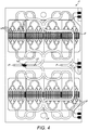
- FIG 4 where the flow from the inlet 3" is shown as a block whit colour and is created in an upper layer which then feeds into channels in a lower layer (indicated in Fig 4 with parallel lines) at the first bifurcation (in Figure 4 it should be understood that the first bifurcation does allow fluid flow and the solid line shown in the figure is simply indicative of a change to different layers).
- the inlet 3" is again configured to have bifurcations 13" splitting the channel into two channels and then further bifurcations result in a plurality of channels 14".
- the channel that is immediately downstream of the inlet 3" is a relatively deep channel that extends through a plurality of layers of the substrate (or through a layer of the substrate to a depth X), however after the initial bifurcation, further channel bifurcations result in the channels becoming smaller, and these smaller channels are formed in a lesser number of substrate layers (or through a different layer of the substrate to a depth >X), typically in the mid-layer of the substrate.
- the positioning of the channels is such that they do not initially all run parallel but do lead to a plurality of groups of parallel channels 14" of smaller circumference downstream of the inlet 3".
- the plurality of parallel channels 14" each flow across electrodes therein.
- Flow can be directed by configuring the channels such that it can flow through multiple first capture areas 2" as shown here.
- the device 1" can be multilayered such that the channel depth can be configured easily.
- a multilayer channel configuration allows for different channels depths leading to the bifurcation zone. It can also allow for a smaller footprint as channels can run in different planes. In this way, pressure is consistently reduced and minimised inside the main capture channels.
- the device also comprises a second area 6", which is downstream of and in fluid communication with the first capture area(s) 2" (or chamber(s) 2").
- a waste outlet provided between the first area 2" and second area 6" which can be provided with a valve, such that when the valve is in a first position, e.g. open, flow is directed through a waste outlet 12" to a waste chamber or area, and when in a second position, e.g. closed, flow does not exit via the waste outlet and instead is directed to the second area.
- the second area comprises a plurality of electrodes 5a" arranged such that enriched sample will flow over them or come into contact with them when the device is in use.
- the electrodes 5a are tuned appropriately, as would be understood by one skilled in the art, to trap target cells using DEP when the electrodes are activated.
- a sample is introduced into the first capture area 2" at a first flow rate.
- the flow rate is regulated by a pump (not shown).
- the electrodes 5" are activated and as such, target cells (e.g. M. Tuberculosis cells or Mycobacterium smegmatis cells ) in the sample are trapped by DEP forces at least part of the surface of the electrodes 5".
- the sample continues to flow through the chamber 2" such that target cells continue to be captured whilst the remaining sample eluate from which the target cells have been removed travels via the waste outlet 12" to a waste reservoir or other area.
- the electrodes 5" are deactivated and the trapped target cells are released from the surface of the electrodes". This results in the media in the first capture area 2" becoming enriched with target cells (providing, of course, that said target cells were in fact present in the original sample). This is referred to herein as the enriched sample.
- the enriched sample does not flow to the waste chamber but instead is then flowed through a channel, in this example a microfluidic channel, into the second chamber or area 6".
- the flow through the second chamber 6" is at a second flow rate that is lower than the flow rate of the sample through the first capture area 2".
Landscapes
- Health & Medical Sciences (AREA)
- Chemical & Material Sciences (AREA)
- Life Sciences & Earth Sciences (AREA)
- Immunology (AREA)
- Hematology (AREA)
- Analytical Chemistry (AREA)
- General Health & Medical Sciences (AREA)
- Physics & Mathematics (AREA)
- Engineering & Computer Science (AREA)
- Molecular Biology (AREA)
- Biomedical Technology (AREA)
- Cell Biology (AREA)
- Urology & Nephrology (AREA)
- Clinical Laboratory Science (AREA)
- Dispersion Chemistry (AREA)
- Pathology (AREA)
- General Physics & Mathematics (AREA)
- Chemical Kinetics & Catalysis (AREA)
- Biochemistry (AREA)
- Fluid Mechanics (AREA)
- Microbiology (AREA)
- Virology (AREA)
- Food Science & Technology (AREA)
- Medicinal Chemistry (AREA)
- Biotechnology (AREA)
- Zoology (AREA)
- Tropical Medicine & Parasitology (AREA)
- Apparatus Associated With Microorganisms And Enzymes (AREA)
- Measuring Or Testing Involving Enzymes Or Micro-Organisms (AREA)
- Investigating, Analyzing Materials By Fluorescence Or Luminescence (AREA)
- Sampling And Sample Adjustment (AREA)
- Automatic Analysis And Handling Materials Therefor (AREA)
- Investigating Or Analyzing Materials By The Use Of Electric Means (AREA)
- Micro-Organisms Or Cultivation Processes Thereof (AREA)
Claims (15)
- Mikrofluidvorrichtung (1, 1', 1") zum Konzentrieren von Zielzellen, dadurch gekennzeichnet, dass die Vorrichtung Folgendes umfasst:einen ersten Einfangbereich (2, 2', 2"), durch den eine Probe geleitet werden kann, wobei der erste Einfangbereich (2, 2', 2") eine Vielzahl von Elektroden (5, 5', 5") umfasst, die so abgestimmt sind, dass sie die Zielzellen unter Verwendung von Di-Elektrophorese (DEP) einfangen, wenn sie aktiviert sind, und die Zielzellen freisetzen, wenn sie deaktiviert sind, wobei die Elektroden (5, 5', 5") so angeordnet sind, dass eine Probe, die durch den Bereich fließt, über sie fließt;einen Abfallbereich stromabwärts des ersten Einfangbereichs (2, 2', 2") und in Fluidverbindung mit dem ersten Einfangbereich (2, 2', 2");einen zweiten Einfangbereich (6, 6', 6") stromabwärts des ersten Einfangbereichs (2, 2', 2") und in Fluidverbindung mit dem ersten Bereich (2, 2', 2"), wobei der zweite Einfangbereich (6, 6', 6") ein kleineres Volumen als der erste Einfangbereich (2, 2', 2") hat, und eine Vielzahl von Elektroden (5a, 5a', 5a") umfasst, die so abgestimmt sind, dass sie Zielzellen unter Verwendung von Di-Elektrophorese (DEP) einfangen, wobei die Elektroden (5a, 5a', 5a") so angeordnet sind, dass eine Probe, die durch den zweiten Bereich (6, 6', 6") fließt, über sie fließt;eine Vielzahl von Durchflussreglern, die so angepasst sind, dass sie sicherstellen, dass die volumetrische Durchflussrate der Probe, die durch den zweiten Einfangsbereich (6, 6', 6") fließt, geringer ist als die volumetrische Durchflussrate der Probe, die durch den ersten Einfangbereich (2, 2', 2") fließt;wobei die Vorrichtung so angeordnet ist, dass, wenn die zum Einfangen der Zielzellen unter Verwendung von Di-Elektrophorese (DEP) im ersten Einfangbereich (2, 2', 2") abgestimmten Elektroden (5, 5', 5") aktiviert werden, Probe aus dem ersten Einfangbereich (2, 2', 2") zum Abfallbereich fließt, und wenn die zum Einfangen der Zielzellen unter Verwendung von Di-Elektrophorese (DEP) im ersten Einfangbereich (2, 2', 2") abgestimmten Elektroden (5, 5', 5") deaktiviert werden, Probe aus dem ersten Einfangbereich (2, 2', 2") zum zweiten Einfangbereich (6, 6', 6") fließt.
- Mikrofluidvorrichtung (1, 1', 1") nach Anspruch 1, wobei der erste Einfangbereich (2, 2', 2") mindestens einen Einlass (3, 3', 3") umfasst, wobei der mindestens eine Einlass (3, 3', 3") in mehrere Kanäle (14', 14") unterteilt ist, wobei jeder Kanal (14', 14") einen kleineren Umfang hat als der mindestens eine Einlass (3, 3', 3") des ersten Einfangbereichs (2, 2', 2").
- Mikrofluidvorrichtung (1, 1', 1") nach einem der Ansprüche 1 oder 2, wobei die Vorrichtung (1, 1', 1") ein Steuermodul umfasst, das einen Fluss eines neuen Puffers oder Mediums in den ersten Einfangbereich (2, 2', 2") und/oder zweiten Bereich (6, 6', 6") einleitet, wenn die Elektroden in dem ersten Einfangbereich (2, 2', 2") oder zweiten Einfangbereich (6, 6', 6") deaktiviert sind.
- Mikrofluidvorrichtung (1, 1', 1") nach einem der vorstehenden Ansprüche, umfassend eine optische Erfassungsvorrichtung.
- Mikrofluidvorrichtung nach Anspruch 4, wobei die optische Erfassungsvorrichtung so angeordnet ist, dass sie Signale aus dem zweiten Bereich (6, 6', 6") erfasst.
- Mikrofluidvorrichtung (1, 1', 1") nach einem der vorstehenden Ansprüche, wobei der Abfallbereich ein Abfallbehälter (9) ist.
- Mikrofluidvorrichtung (1, 1', 1") nach einem der vorstehenden Ansprüche, wobei die Durchflussregler Pumpen sind.
- Verfahren zum Konzentrieren von Zielpartikeln in einer Probe, das die folgenden Schritte umfasst:Bereitstellen einer Mikrofluidvorrichtung (1, 1', 1") nach einem der vorstehenden Ansprüche;Einführen einer Probe in den ersten Einfangbereich (2, 2', 2") und Durchfließen der Probe durch den ersten Einfangbereich (2, 2', 2") mit einer ersten Durchflussrate, wobei die erste Vielzahl von Elektroden (5, 5', 5") aktiviert und so angeordnet ist, dass sie jegliche Zielpartikel einfängt, undwobei der Probenstrom aus dem ersten Einfangbereich (2, 2', 2") in den Abfallbereich geleitet wird;Deaktivieren der ersten Vielzahl von Elektroden (5, 5', 5") und Freisetzen von eingefangenen Zielpartikeln von der ersten Vielzahl von Elektroden (5, 5', 5") zur Bereitstellung einer angereicherten Probe, und auch Leiten des Probenflusses aus dem ersten Einfangbereich (2, 2', 2") heraus zu dem zweiten Bereich (6, 6', 6");Einleiten der angereicherten Probe in den zweiten Bereich (6, 6', 6") und Durchfließen der angereicherten Probe durch den zweiten Bereich (6, 6', 6") mit einer zweiten Durchflussrate, die niedriger ist als die erste Durchflussrate, und mit der zweiten Vielzahl von Elektroden (5a, 5a', 5a"), die so angeordnet und aktiviert sind, dass sie Zielpartikel einfangen.
- Verfahren zum Konzentrieren von Zielpartikeln nach Anspruch 8, wobei der Schritt des Freisetzens von eingefangenen Zielpartikeln von der ersten Vielzahl von Elektroden (5, 5', 5") zur Bereitstellung einer angereicherten Probe das Deaktivieren der Elektroden (5, 5', 5") in dem ersten Einfangbereich (2, 2', 2") nach einem definierten Zeitraum umfasst, um eingefangene Zielpartikel freizusetzen und eine angereicherte Probe bereitzustellen.
- Verfahren zum Konzentrieren von Zielpartikeln nach einem der Ansprüche 8 oder 9, wobei vor dem Freisetzen der eingefangenen Zielpartikel im ersten Einfangbereich (2, 2', 2") ein neuer Puffer oder ein neues Medium in den ersten Einfangbereich (2, 2', 2") geleitet wird.
- Verfahren zum Konzentrieren von Zielpartikeln nach einem der Ansprüche 8 bis 10, wobei die Probe einen niedrigen Salzgehalt oder eine niedrige lonenstärke aufweist.
- Verfahren zum Konzentrieren von Zielpartikeln nach einem der Ansprüche 8 bis 11, wobei das Verfahren den weiteren Schritt des Deaktivierens der Elektroden (5a, 5a', 5a") im zweiten Bereich (6, 6', 6") nach einem Zeitraum umfasst, um eingeschlossene Zielzellen zur Bereitstellung einer weiteren angereicherten Probe freizusetzen.
- Verfahren zum Konzentrieren von Zielpartikeln nach Anspruch 12, wobei vor dem Deaktivieren der Elektroden (5a, 5a', 5a") im zweiten Bereich (6, 6', 6") ein neuer Puffer oder ein neues Medium in den zweiten Bereich (6, 6', 6") geleitet wird.
- Verfahren zum Konzentrieren von Zielzellen nach einem der Ansprüche 8 bis 13, wobei eine optische Erfassungsvorrichtung vorgesehen ist und Zielpartikel unter Verwendung der optischen Erfassungsvorrichtung betrachtet werden.
- Verfahren zum Konzentrieren von Zielpartikeln nach Anspruch 14, wobei die optische Erfassungsvorrichtung so angeordnet ist, dass sie Signale aus dem zweiten Bereich (6, 6', 6") erfasst.
Applications Claiming Priority (4)
| Application Number | Priority Date | Filing Date | Title |
|---|---|---|---|
| GBGB1610830.0A GB201610830D0 (en) | 2016-06-21 | 2016-06-21 | Improved target cell concentration using dielectrophoresis (DEP) |
| GBGB1707566.4A GB201707566D0 (en) | 2017-05-11 | 2017-05-11 | Improved target cell concentration using dielectrophoresis (DEP) |
| PCT/EP2017/065019 WO2017220534A1 (en) | 2016-06-21 | 2017-06-20 | Improved target cell concentration using dielectrophoresis (dep) |
| EP17737217.4A EP3471879B1 (de) | 2016-06-21 | 2017-06-20 | Verbesserte zielzellenkonzentration mittels dielektrophorese (dep) |
Related Parent Applications (2)
| Application Number | Title | Priority Date | Filing Date |
|---|---|---|---|
| EP17737217.4A Division-Into EP3471879B1 (de) | 2016-06-21 | 2017-06-20 | Verbesserte zielzellenkonzentration mittels dielektrophorese (dep) |
| EP17737217.4A Division EP3471879B1 (de) | 2016-06-21 | 2017-06-20 | Verbesserte zielzellenkonzentration mittels dielektrophorese (dep) |
Publications (2)
| Publication Number | Publication Date |
|---|---|
| EP3693087A1 EP3693087A1 (de) | 2020-08-12 |
| EP3693087B1 true EP3693087B1 (de) | 2021-09-01 |
Family
ID=59298434
Family Applications (2)
| Application Number | Title | Priority Date | Filing Date |
|---|---|---|---|
| EP20167555.0A Active EP3693087B1 (de) | 2016-06-21 | 2017-06-20 | Verbesserte zielzellkonzentration mittels dielektrophorese (dep) |
| EP17737217.4A Active EP3471879B1 (de) | 2016-06-21 | 2017-06-20 | Verbesserte zielzellenkonzentration mittels dielektrophorese (dep) |
Family Applications After (1)
| Application Number | Title | Priority Date | Filing Date |
|---|---|---|---|
| EP17737217.4A Active EP3471879B1 (de) | 2016-06-21 | 2017-06-20 | Verbesserte zielzellenkonzentration mittels dielektrophorese (dep) |
Country Status (6)
| Country | Link |
|---|---|
| US (2) | US10710075B2 (de) |
| EP (2) | EP3693087B1 (de) |
| JP (2) | JP6641032B2 (de) |
| ES (2) | ES2802261T3 (de) |
| PL (1) | PL3471879T3 (de) |
| WO (1) | WO2017220534A1 (de) |
Families Citing this family (2)
| Publication number | Priority date | Publication date | Assignee | Title |
|---|---|---|---|---|
| GB2577074B (en) * | 2018-09-12 | 2022-06-01 | Quantumdx Group Ltd | Microfluidic device with DEP arrays |
| US20240316552A1 (en) * | 2021-06-30 | 2024-09-26 | Quantumdx Group Limited | Microfluidic device for concentrating target particles in a fluid sample using dielectrophoresis |
Family Cites Families (9)
| Publication number | Priority date | Publication date | Assignee | Title |
|---|---|---|---|---|
| US6576459B2 (en) * | 2001-03-23 | 2003-06-10 | The Regents Of The University Of California | Sample preparation and detection device for infectious agents |
| US20040011650A1 (en) * | 2002-07-22 | 2004-01-22 | Frederic Zenhausern | Method and apparatus for manipulating polarizable analytes via dielectrophoresis |
| US7476360B2 (en) * | 2003-12-09 | 2009-01-13 | Genefluidics, Inc. | Cartridge for use with electrochemical sensor |
| GB0618966D0 (en) * | 2006-09-26 | 2006-11-08 | Iti Scotland Ltd | Cartridge system |
| WO2010080978A2 (en) * | 2009-01-08 | 2010-07-15 | The General Hospital Corporation | Pre-depletion of leukocytes in whole blood samples prior to the capture of whole blood sample components |
| US9005987B2 (en) | 2009-04-16 | 2015-04-14 | University Of Southern California | Methods for quantitative target detection and related devices and systems |
| US9857333B2 (en) * | 2012-10-31 | 2018-01-02 | Berkeley Lights, Inc. | Pens for biological micro-objects |
| US8934700B2 (en) * | 2013-03-04 | 2015-01-13 | Caliper Life Sciences, Inc. | High-throughput single-cell imaging, sorting, and isolation |
| GB201311679D0 (en) * | 2013-06-28 | 2013-08-14 | Ibm | Microfluidic chip with dielectrophoretic electrodes extending in hydrophilic flow path |
-
2017
- 2017-06-20 PL PL17737217T patent/PL3471879T3/pl unknown
- 2017-06-20 US US16/311,147 patent/US10710075B2/en active Active
- 2017-06-20 ES ES17737217T patent/ES2802261T3/es active Active
- 2017-06-20 WO PCT/EP2017/065019 patent/WO2017220534A1/en not_active Ceased
- 2017-06-20 EP EP20167555.0A patent/EP3693087B1/de active Active
- 2017-06-20 JP JP2018566214A patent/JP6641032B2/ja active Active
- 2017-06-20 ES ES20167555T patent/ES2899107T3/es active Active
- 2017-06-20 EP EP17737217.4A patent/EP3471879B1/de active Active
-
2019
- 2019-12-26 JP JP2019236783A patent/JP6991192B2/ja active Active
-
2020
- 2020-06-12 US US16/900,703 patent/US11850593B2/en active Active
Also Published As
| Publication number | Publication date |
|---|---|
| JP6641032B2 (ja) | 2020-02-05 |
| EP3471879B1 (de) | 2020-05-13 |
| EP3471879A1 (de) | 2019-04-24 |
| US10710075B2 (en) | 2020-07-14 |
| US20200298235A1 (en) | 2020-09-24 |
| EP3693087A1 (de) | 2020-08-12 |
| ES2802261T3 (es) | 2021-01-18 |
| PL3471879T3 (pl) | 2020-11-16 |
| ES2899107T3 (es) | 2022-03-10 |
| WO2017220534A1 (en) | 2017-12-28 |
| US11850593B2 (en) | 2023-12-26 |
| JP6991192B2 (ja) | 2022-01-12 |
| US20190176151A1 (en) | 2019-06-13 |
| JP2020099325A (ja) | 2020-07-02 |
| JP2019525739A (ja) | 2019-09-12 |
Similar Documents
| Publication | Publication Date | Title |
|---|---|---|
| Zhang et al. | Fundamentals and applications of inertial microfluidics: a review | |
| EP3058365B1 (de) | Mikrofluidischer sortierer zur erkennung und isolation von zellen | |
| JP5920895B2 (ja) | マイクロ流体捕獲渦を使用して不均一溶液から細胞を単離する方法及びデバイス | |
| CN107110766B (zh) | 在微流体装置中对颗粒的联合分选和浓缩 | |
| JP5684224B2 (ja) | マイクロチャネルにおける粒子集束のためのシステムおよび方法 | |
| EP2964388B1 (de) | Einzellige bildgebung mit hohem durchsatz, sortierung und isolierung | |
| Ranchon et al. | DNA separation and enrichment using electro-hydrodynamic bidirectional flows in viscoelastic liquids | |
| EP1707965A1 (de) | Vorrichtung zur chemischen analyse und chemisches analyseverfahren | |
| US20080067068A1 (en) | DC-dielectrophoresis microfluidic apparatus, and applications of same | |
| US11850593B2 (en) | Target cell concentration using dielectrophoresis (DEP) | |
| HK40034581A (en) | Improved target cell concentration using dielectrophoresis (dep) | |
| HK40034581B (en) | Improved target cell concentration using dielectrophoresis (dep) | |
| HK40007222B (en) | Improved target cell concentration using dielectrophoresis (dep) | |
| HK40007222A (en) | Improved target cell concentration using dielectrophoresis (dep) | |
| JP4587215B2 (ja) | 成分分離機構と成分分離方法 | |
| Zhang | Particle inertial focusing and separation in serpentine microchannels: mechanisms and applications | |
| Zhang et al. | On-chip sample preparations for point-of-care cellular analysis of blood | |
| Morgan | Microfluidic devices to facilitate in-flow medium exchange, and tuneable size-based sorting, of microspheres | |
| Li | Development of microfluidic devices for cell based analysis | |
| Kumar | Inertio-and Elasto-Magnetic Fractionation of Multiple Microparticles in Newtonian and Non-Newtonian Fluid | |
| HK1242781A1 (en) | Combined sorting and concentrating particles in a microfluidic device |
Legal Events
| Date | Code | Title | Description |
|---|---|---|---|
| PUAI | Public reference made under article 153(3) epc to a published international application that has entered the european phase |
Free format text: ORIGINAL CODE: 0009012 |
|
| STAA | Information on the status of an ep patent application or granted ep patent |
Free format text: STATUS: THE APPLICATION HAS BEEN PUBLISHED |
|
| AC | Divisional application: reference to earlier application |
Ref document number: 3471879 Country of ref document: EP Kind code of ref document: P |
|
| AK | Designated contracting states |
Kind code of ref document: A1 Designated state(s): AL AT BE BG CH CY CZ DE DK EE ES FI FR GB GR HR HU IE IS IT LI LT LU LV MC MK MT NL NO PL PT RO RS SE SI SK SM TR |
|
| STAA | Information on the status of an ep patent application or granted ep patent |
Free format text: STATUS: REQUEST FOR EXAMINATION WAS MADE |
|
| 17P | Request for examination filed |
Effective date: 20210201 |
|
| RBV | Designated contracting states (corrected) |
Designated state(s): AL AT BE BG CH CY CZ DE DK EE ES FI FR GB GR HR HU IE IS IT LI LT LU LV MC MK MT NL NO PL PT RO RS SE SI SK SM TR |
|
| GRAP | Despatch of communication of intention to grant a patent |
Free format text: ORIGINAL CODE: EPIDOSNIGR1 |
|
| STAA | Information on the status of an ep patent application or granted ep patent |
Free format text: STATUS: GRANT OF PATENT IS INTENDED |
|
| REG | Reference to a national code |
Ref country code: HK Ref legal event code: DE Ref document number: 40034581 Country of ref document: HK |
|
| INTG | Intention to grant announced |
Effective date: 20210412 |
|
| GRAS | Grant fee paid |
Free format text: ORIGINAL CODE: EPIDOSNIGR3 |
|
| GRAA | (expected) grant |
Free format text: ORIGINAL CODE: 0009210 |
|
| STAA | Information on the status of an ep patent application or granted ep patent |
Free format text: STATUS: THE PATENT HAS BEEN GRANTED |
|
| AC | Divisional application: reference to earlier application |
Ref document number: 3471879 Country of ref document: EP Kind code of ref document: P |
|
| AK | Designated contracting states |
Kind code of ref document: B1 Designated state(s): AL AT BE BG CH CY CZ DE DK EE ES FI FR GB GR HR HU IE IS IT LI LT LU LV MC MK MT NL NO PL PT RO RS SE SI SK SM TR |
|
| REG | Reference to a national code |
Ref country code: GB Ref legal event code: FG4D |
|
| REG | Reference to a national code |
Ref country code: CH Ref legal event code: EP Ref country code: AT Ref legal event code: REF Ref document number: 1425633 Country of ref document: AT Kind code of ref document: T Effective date: 20210915 |
|
| REG | Reference to a national code |
Ref country code: DE Ref legal event code: R096 Ref document number: 602017045515 Country of ref document: DE |
|
| REG | Reference to a national code |
Ref country code: IE Ref legal event code: FG4D |
|
| REG | Reference to a national code |
Ref country code: SE Ref legal event code: TRGR |
|
| REG | Reference to a national code |
Ref country code: NL Ref legal event code: FP |
|
| REG | Reference to a national code |
Ref country code: LT Ref legal event code: MG9D |
|
| PG25 | Lapsed in a contracting state [announced via postgrant information from national office to epo] |
Ref country code: BG Free format text: LAPSE BECAUSE OF FAILURE TO SUBMIT A TRANSLATION OF THE DESCRIPTION OR TO PAY THE FEE WITHIN THE PRESCRIBED TIME-LIMIT Effective date: 20211201 Ref country code: LT Free format text: LAPSE BECAUSE OF FAILURE TO SUBMIT A TRANSLATION OF THE DESCRIPTION OR TO PAY THE FEE WITHIN THE PRESCRIBED TIME-LIMIT Effective date: 20210901 Ref country code: NO Free format text: LAPSE BECAUSE OF FAILURE TO SUBMIT A TRANSLATION OF THE DESCRIPTION OR TO PAY THE FEE WITHIN THE PRESCRIBED TIME-LIMIT Effective date: 20211201 Ref country code: FI Free format text: LAPSE BECAUSE OF FAILURE TO SUBMIT A TRANSLATION OF THE DESCRIPTION OR TO PAY THE FEE WITHIN THE PRESCRIBED TIME-LIMIT Effective date: 20210901 Ref country code: HR Free format text: LAPSE BECAUSE OF FAILURE TO SUBMIT A TRANSLATION OF THE DESCRIPTION OR TO PAY THE FEE WITHIN THE PRESCRIBED TIME-LIMIT Effective date: 20210901 Ref country code: RS Free format text: LAPSE BECAUSE OF FAILURE TO SUBMIT A TRANSLATION OF THE DESCRIPTION OR TO PAY THE FEE WITHIN THE PRESCRIBED TIME-LIMIT Effective date: 20210901 |
|
| REG | Reference to a national code |
Ref country code: AT Ref legal event code: MK05 Ref document number: 1425633 Country of ref document: AT Kind code of ref document: T Effective date: 20210901 |
|
| PG25 | Lapsed in a contracting state [announced via postgrant information from national office to epo] |
Ref country code: PL Free format text: LAPSE BECAUSE OF FAILURE TO SUBMIT A TRANSLATION OF THE DESCRIPTION OR TO PAY THE FEE WITHIN THE PRESCRIBED TIME-LIMIT Effective date: 20210901 Ref country code: LV Free format text: LAPSE BECAUSE OF FAILURE TO SUBMIT A TRANSLATION OF THE DESCRIPTION OR TO PAY THE FEE WITHIN THE PRESCRIBED TIME-LIMIT Effective date: 20210901 Ref country code: GR Free format text: LAPSE BECAUSE OF FAILURE TO SUBMIT A TRANSLATION OF THE DESCRIPTION OR TO PAY THE FEE WITHIN THE PRESCRIBED TIME-LIMIT Effective date: 20211202 |
|
| REG | Reference to a national code |
Ref country code: ES Ref legal event code: FG2A Ref document number: 2899107 Country of ref document: ES Kind code of ref document: T3 Effective date: 20220310 |
|
| PG25 | Lapsed in a contracting state [announced via postgrant information from national office to epo] |
Ref country code: AT Free format text: LAPSE BECAUSE OF FAILURE TO SUBMIT A TRANSLATION OF THE DESCRIPTION OR TO PAY THE FEE WITHIN THE PRESCRIBED TIME-LIMIT Effective date: 20210901 |
|
| PG25 | Lapsed in a contracting state [announced via postgrant information from national office to epo] |
Ref country code: IS Free format text: LAPSE BECAUSE OF FAILURE TO SUBMIT A TRANSLATION OF THE DESCRIPTION OR TO PAY THE FEE WITHIN THE PRESCRIBED TIME-LIMIT Effective date: 20220101 Ref country code: SM Free format text: LAPSE BECAUSE OF FAILURE TO SUBMIT A TRANSLATION OF THE DESCRIPTION OR TO PAY THE FEE WITHIN THE PRESCRIBED TIME-LIMIT Effective date: 20210901 Ref country code: SK Free format text: LAPSE BECAUSE OF FAILURE TO SUBMIT A TRANSLATION OF THE DESCRIPTION OR TO PAY THE FEE WITHIN THE PRESCRIBED TIME-LIMIT Effective date: 20210901 Ref country code: RO Free format text: LAPSE BECAUSE OF FAILURE TO SUBMIT A TRANSLATION OF THE DESCRIPTION OR TO PAY THE FEE WITHIN THE PRESCRIBED TIME-LIMIT Effective date: 20210901 Ref country code: PT Free format text: LAPSE BECAUSE OF FAILURE TO SUBMIT A TRANSLATION OF THE DESCRIPTION OR TO PAY THE FEE WITHIN THE PRESCRIBED TIME-LIMIT Effective date: 20220103 Ref country code: EE Free format text: LAPSE BECAUSE OF FAILURE TO SUBMIT A TRANSLATION OF THE DESCRIPTION OR TO PAY THE FEE WITHIN THE PRESCRIBED TIME-LIMIT Effective date: 20210901 Ref country code: CZ Free format text: LAPSE BECAUSE OF FAILURE TO SUBMIT A TRANSLATION OF THE DESCRIPTION OR TO PAY THE FEE WITHIN THE PRESCRIBED TIME-LIMIT Effective date: 20210901 Ref country code: AL Free format text: LAPSE BECAUSE OF FAILURE TO SUBMIT A TRANSLATION OF THE DESCRIPTION OR TO PAY THE FEE WITHIN THE PRESCRIBED TIME-LIMIT Effective date: 20210901 |
|
| REG | Reference to a national code |
Ref country code: DE Ref legal event code: R097 Ref document number: 602017045515 Country of ref document: DE |
|
| PLBE | No opposition filed within time limit |
Free format text: ORIGINAL CODE: 0009261 |
|
| STAA | Information on the status of an ep patent application or granted ep patent |
Free format text: STATUS: NO OPPOSITION FILED WITHIN TIME LIMIT |
|
| PG25 | Lapsed in a contracting state [announced via postgrant information from national office to epo] |
Ref country code: DK Free format text: LAPSE BECAUSE OF FAILURE TO SUBMIT A TRANSLATION OF THE DESCRIPTION OR TO PAY THE FEE WITHIN THE PRESCRIBED TIME-LIMIT Effective date: 20210901 |
|
| 26N | No opposition filed |
Effective date: 20220602 |
|
| PG25 | Lapsed in a contracting state [announced via postgrant information from national office to epo] |
Ref country code: SI Free format text: LAPSE BECAUSE OF FAILURE TO SUBMIT A TRANSLATION OF THE DESCRIPTION OR TO PAY THE FEE WITHIN THE PRESCRIBED TIME-LIMIT Effective date: 20210901 |
|
| PG25 | Lapsed in a contracting state [announced via postgrant information from national office to epo] |
Ref country code: MC Free format text: LAPSE BECAUSE OF FAILURE TO SUBMIT A TRANSLATION OF THE DESCRIPTION OR TO PAY THE FEE WITHIN THE PRESCRIBED TIME-LIMIT Effective date: 20210901 |
|
| REG | Reference to a national code |
Ref country code: CH Ref legal event code: PL |
|
| REG | Reference to a national code |
Ref country code: BE Ref legal event code: MM Effective date: 20220630 |
|
| PG25 | Lapsed in a contracting state [announced via postgrant information from national office to epo] |
Ref country code: LU Free format text: LAPSE BECAUSE OF NON-PAYMENT OF DUE FEES Effective date: 20220620 Ref country code: LI Free format text: LAPSE BECAUSE OF NON-PAYMENT OF DUE FEES Effective date: 20220630 Ref country code: IE Free format text: LAPSE BECAUSE OF NON-PAYMENT OF DUE FEES Effective date: 20220620 Ref country code: CH Free format text: LAPSE BECAUSE OF NON-PAYMENT OF DUE FEES Effective date: 20220630 |
|
| PG25 | Lapsed in a contracting state [announced via postgrant information from national office to epo] |
Ref country code: BE Free format text: LAPSE BECAUSE OF NON-PAYMENT OF DUE FEES Effective date: 20220630 |
|
| P01 | Opt-out of the competence of the unified patent court (upc) registered |
Effective date: 20230516 |
|
| PG25 | Lapsed in a contracting state [announced via postgrant information from national office to epo] |
Ref country code: MK Free format text: LAPSE BECAUSE OF FAILURE TO SUBMIT A TRANSLATION OF THE DESCRIPTION OR TO PAY THE FEE WITHIN THE PRESCRIBED TIME-LIMIT Effective date: 20210901 Ref country code: CY Free format text: LAPSE BECAUSE OF FAILURE TO SUBMIT A TRANSLATION OF THE DESCRIPTION OR TO PAY THE FEE WITHIN THE PRESCRIBED TIME-LIMIT Effective date: 20210901 |
|
| PG25 | Lapsed in a contracting state [announced via postgrant information from national office to epo] |
Ref country code: HU Free format text: LAPSE BECAUSE OF FAILURE TO SUBMIT A TRANSLATION OF THE DESCRIPTION OR TO PAY THE FEE WITHIN THE PRESCRIBED TIME-LIMIT; INVALID AB INITIO Effective date: 20170620 |
|
| PG25 | Lapsed in a contracting state [announced via postgrant information from national office to epo] |
Ref country code: MT Free format text: LAPSE BECAUSE OF FAILURE TO SUBMIT A TRANSLATION OF THE DESCRIPTION OR TO PAY THE FEE WITHIN THE PRESCRIBED TIME-LIMIT Effective date: 20210901 |
|
| PGFP | Annual fee paid to national office [announced via postgrant information from national office to epo] |
Ref country code: DE Payment date: 20250603 Year of fee payment: 9 |
|
| PGFP | Annual fee paid to national office [announced via postgrant information from national office to epo] |
Ref country code: GB Payment date: 20250520 Year of fee payment: 9 |
|
| PGFP | Annual fee paid to national office [announced via postgrant information from national office to epo] |
Ref country code: NL Payment date: 20250620 Year of fee payment: 9 |
|
| PGFP | Annual fee paid to national office [announced via postgrant information from national office to epo] |
Ref country code: FR Payment date: 20250606 Year of fee payment: 9 |
|
| PGFP | Annual fee paid to national office [announced via postgrant information from national office to epo] |
Ref country code: SE Payment date: 20250602 Year of fee payment: 9 |
|
| PGFP | Annual fee paid to national office [announced via postgrant information from national office to epo] |
Ref country code: ES Payment date: 20250702 Year of fee payment: 9 |
|
| PGFP | Annual fee paid to national office [announced via postgrant information from national office to epo] |
Ref country code: IT Payment date: 20250617 Year of fee payment: 9 |
|
| PG25 | Lapsed in a contracting state [announced via postgrant information from national office to epo] |
Ref country code: TR Free format text: LAPSE BECAUSE OF FAILURE TO SUBMIT A TRANSLATION OF THE DESCRIPTION OR TO PAY THE FEE WITHIN THE PRESCRIBED TIME-LIMIT Effective date: 20210901 |