EP3691055A1 - Connector fitting device - Google Patents
Connector fitting device Download PDFInfo
- Publication number
- EP3691055A1 EP3691055A1 EP20152845.2A EP20152845A EP3691055A1 EP 3691055 A1 EP3691055 A1 EP 3691055A1 EP 20152845 A EP20152845 A EP 20152845A EP 3691055 A1 EP3691055 A1 EP 3691055A1
- Authority
- EP
- European Patent Office
- Prior art keywords
- connector
- axis
- fitting device
- arm
- gripper
- Prior art date
- Legal status (The legal status is an assumption and is not a legal conclusion. Google has not performed a legal analysis and makes no representation as to the accuracy of the status listed.)
- Granted
Links
Images




Classifications
-
- H—ELECTRICITY
- H01—ELECTRIC ELEMENTS
- H01R—ELECTRICALLY-CONDUCTIVE CONNECTIONS; STRUCTURAL ASSOCIATIONS OF A PLURALITY OF MUTUALLY-INSULATED ELECTRICAL CONNECTING ELEMENTS; COUPLING DEVICES; CURRENT COLLECTORS
- H01R43/00—Apparatus or processes specially adapted for manufacturing, assembling, maintaining, or repairing of line connectors or current collectors or for joining electric conductors
- H01R43/26—Apparatus or processes specially adapted for manufacturing, assembling, maintaining, or repairing of line connectors or current collectors or for joining electric conductors for engaging or disengaging the two parts of a coupling device
-
- B—PERFORMING OPERATIONS; TRANSPORTING
- B25—HAND TOOLS; PORTABLE POWER-DRIVEN TOOLS; MANIPULATORS
- B25J—MANIPULATORS; CHAMBERS PROVIDED WITH MANIPULATION DEVICES
- B25J15/00—Gripping heads and other end effectors
- B25J15/0028—Gripping heads and other end effectors with movable, e.g. pivoting gripping jaw surfaces
-
- B—PERFORMING OPERATIONS; TRANSPORTING
- B25—HAND TOOLS; PORTABLE POWER-DRIVEN TOOLS; MANIPULATORS
- B25J—MANIPULATORS; CHAMBERS PROVIDED WITH MANIPULATION DEVICES
- B25J15/00—Gripping heads and other end effectors
- B25J15/009—Gripping heads and other end effectors with pins for accurately positioning the object on the gripping head
-
- B—PERFORMING OPERATIONS; TRANSPORTING
- B25—HAND TOOLS; PORTABLE POWER-DRIVEN TOOLS; MANIPULATORS
- B25J—MANIPULATORS; CHAMBERS PROVIDED WITH MANIPULATION DEVICES
- B25J15/00—Gripping heads and other end effectors
- B25J15/02—Gripping heads and other end effectors servo-actuated
- B25J15/0253—Gripping heads and other end effectors servo-actuated comprising parallel grippers
-
- B—PERFORMING OPERATIONS; TRANSPORTING
- B25—HAND TOOLS; PORTABLE POWER-DRIVEN TOOLS; MANIPULATORS
- B25J—MANIPULATORS; CHAMBERS PROVIDED WITH MANIPULATION DEVICES
- B25J9/00—Program-controlled manipulators
- B25J9/02—Program-controlled manipulators characterised by movement of the arms, e.g. cartesian coordinate type
- B25J9/04—Program-controlled manipulators characterised by movement of the arms, e.g. cartesian coordinate type by rotating at least one arm, excluding the head movement itself, e.g. cylindrical coordinate type or polar coordinate type
- B25J9/046—Revolute coordinate type
-
- B—PERFORMING OPERATIONS; TRANSPORTING
- B25—HAND TOOLS; PORTABLE POWER-DRIVEN TOOLS; MANIPULATORS
- B25J—MANIPULATORS; CHAMBERS PROVIDED WITH MANIPULATION DEVICES
- B25J9/00—Program-controlled manipulators
- B25J9/16—Program controls
- B25J9/1679—Program controls characterised by the tasks executed
- B25J9/1687—Assembly, peg and hole, palletising, straight line, weaving pattern movement
-
- B—PERFORMING OPERATIONS; TRANSPORTING
- B60—VEHICLES IN GENERAL
- B60R—VEHICLES, VEHICLE FITTINGS, OR VEHICLE PARTS, NOT OTHERWISE PROVIDED FOR
- B60R16/00—Electric or fluid circuits specially adapted for vehicles and not otherwise provided for; Arrangement of elements of electric or fluid circuits specially adapted for vehicles and not otherwise provided for
- B60R16/02—Electric or fluid circuits specially adapted for vehicles and not otherwise provided for; Arrangement of elements of electric or fluid circuits specially adapted for vehicles and not otherwise provided for electric constitutive elements
- B60R16/023—Electric or fluid circuits specially adapted for vehicles and not otherwise provided for; Arrangement of elements of electric or fluid circuits specially adapted for vehicles and not otherwise provided for electric constitutive elements for transmission of signals between vehicle parts or subsystems
-
- H—ELECTRICITY
- H01—ELECTRIC ELEMENTS
- H01R—ELECTRICALLY-CONDUCTIVE CONNECTIONS; STRUCTURAL ASSOCIATIONS OF A PLURALITY OF MUTUALLY-INSULATED ELECTRICAL CONNECTING ELEMENTS; COUPLING DEVICES; CURRENT COLLECTORS
- H01R13/00—Details of coupling devices of the kinds covered by groups H01R12/70 or H01R24/00 - H01R33/00
- H01R13/46—Bases; Cases
- H01R13/50—Bases; Cases formed as an integral body
-
- H—ELECTRICITY
- H01—ELECTRIC ELEMENTS
- H01R—ELECTRICALLY-CONDUCTIVE CONNECTIONS; STRUCTURAL ASSOCIATIONS OF A PLURALITY OF MUTUALLY-INSULATED ELECTRICAL CONNECTING ELEMENTS; COUPLING DEVICES; CURRENT COLLECTORS
- H01R13/00—Details of coupling devices of the kinds covered by groups H01R12/70 or H01R24/00 - H01R33/00
- H01R13/46—Bases; Cases
- H01R13/516—Means for holding or embracing insulating body, e.g. casing, hoods
-
- H—ELECTRICITY
- H01—ELECTRIC ELEMENTS
- H01R—ELECTRICALLY-CONDUCTIVE CONNECTIONS; STRUCTURAL ASSOCIATIONS OF A PLURALITY OF MUTUALLY-INSULATED ELECTRICAL CONNECTING ELEMENTS; COUPLING DEVICES; CURRENT COLLECTORS
- H01R2107/00—Four or more poles
-
- H—ELECTRICITY
- H01—ELECTRIC ELEMENTS
- H01R—ELECTRICALLY-CONDUCTIVE CONNECTIONS; STRUCTURAL ASSOCIATIONS OF A PLURALITY OF MUTUALLY-INSULATED ELECTRICAL CONNECTING ELEMENTS; COUPLING DEVICES; CURRENT COLLECTORS
- H01R2201/00—Connectors or connections adapted for particular applications
- H01R2201/26—Connectors or connections adapted for particular applications for vehicles
Definitions
- the present disclosure relates to a connector fitting device for fitting a connector to an opponent connector.
- a hybrid vehicle 100 includes wire harnesses WH1 to WH3.
- the wire harnesses WH1 to WH3 electrically connect a junction box 102, which is connected to a battery 101, with an inverter unit 103.
- the wire harness WH1 is connected to the junction box 102.
- the wire harness WH2 is connected to the inverter unit 103.
- the wire harness WH3 electrically connects the wire harnesses WH1 and WH2.
- Connections between a connector 110 of the junction box 102 and a connector of the wire harness WH1 (not illustrated), a connector 111 of the inverter unit 103 and a connector of the wire harness WH2 (not illustrated), a connector 112 of the wire harness WH1 and a connector 113 of the wire harness WH3, and a connector 114 of the wire harness WH2 and a connector 115 of the wire harness WH3 are achieved by mate fitting.
- a fitting operation of the connectors is a burden to the operator, and there has been a need for reducing the burden.
- the present disclosure has been made to solve the above-described problem, and it is an object of the present disclosure to provide a connector fitting device that reduces a burden to an operator who performs a fitting operation the connectors.
- One aspect of the present disclosure is a connector fitting device for fitting a first connector to a second connector, including a movable arm body connected to a base on a base end side of the movable arm body, and a gripper connected to a distal end side of the movable arm body and capable of gripping the first connector, in which the connector fitting device configured to move the gripper to an arbitrary position in a three-dimensional space and in an arbitrary direction in the three-dimensional space.
- the movable arm body moves the gripper to a connector feeding position, the gripper grips the connector, and the movable arm body moves the gripped connector to a fitting position to an opponent connector, whereby the movable arm body moves the connector in a fitting direction to the opponent connector for fitting.
- FIGs. 1 to 6 illustrate a first embodiment of the present disclosure.
- a housing 2 for various sensors, an electronic control unit (ECU), and so on is mounted in the vehicle 1.
- a male connector 10 serving as an opponent connector (second connector) is attached to the housing 2.
- the male connector 10 is fixed at a determined position and in a determined direction in the vehicle 1.
- a female connector (first connector) 20 connected to the terminal of a wire harness WH is fitted to the male connector 10, whereby the above-described sensors and the electronic control unit are connected to the system of the vehicle via a wire harness (cable) WH.
- the female connector 20 of the wire harness WH is fitted to the male connector 10 fixed at a determined position and in a determined direction in the vehicle 1 using a connector fitting device (hereinafter referred to as a fitting device) 30.
- a connector fitting device hereinafter referred to as a fitting device 30.
- the female connector 20 connected to the wire harness WH is arranged at a feeding position as illustrated in FIG. 2(a) .
- the female connector 20 is conveyed to the position of the male connector 10 fixed at the determined position and in the determined direction in the vehicle 1, and is fitted to the male connector 10 as illustrated in FIG. 2(b) .
- the male connector 10 includes a housing 12 having a connector fitting chamber (hereinafter referred to as a fitting chamber) 11, and a plurality of male terminals (not illustrated) arranged in a protruding manner in the fitting chamber 11 of the housing 12.
- the fitting chamber 11 has a substantially rectangular parallelepiped space, with one surface opened to the outside. Through this opening, the female connector 20 is inserted into and fitted to the male connector 10.
- An opponent housing lock (not illustrated) is provided in the fitting chamber 11.
- the female connector 20 includes a housing 22 having a plurality of terminal accommodating chambers 21 each having an open front surface, and female terminals (not illustrated) each accommodated in the terminal accommodating chambers 21.
- the housing 22 has a substantially rectangular parallelepiped shape.
- a housing lock 23 is provided on the upper surface of the housing 22.
- a surface to be clamped 24 is formed at a rearward position of both side surfaces of the housing 22.
- the surface to be clamped 24 is, for example, a flat surface and is clamped by a pair of clamping portions 41 of the fitting device 30 described below.
- the wire harness WH is connected to individual female terminals (not illustrated) and pulled out from the rear surface of the housing 22. In other words, the female connector 20 is connected to the end of the wire harness WH.
- the fitting device 30 includes a movable arm body 32 connected to a base 31 on a base end side of the movable arm body 32, and a gripper 40 connected to the distal end side (tip end side) of the movable arm body 32.
- the movable arm body 32 includes a device main body 33, a first arm 34, a second arm 35, and a third arm 36.
- the device main body 33 is provided on the base 31. Further, the device main body 33 can rotate about an axis (first axis) C1.
- the axis (first axis) C1 is, for example, orthogonal to a horizontal plane. In this case, the device main body 33 rotates in the horizontal plane.
- the first arm 34 is rotatably connected to the distal end portion (tip end portion) of the device main body 33.
- the first arm 34 can rotate about an axis (second axis) C2.
- the axis (second axis) C2 is orthogonal to the axis (first axis) C1.
- the first arm 34 rotates in a vertical plane which is orthogonal to the above-described horizontal plane.
- the second arm 35 is rotatably connected to the distal end portion of the first arm 34.
- the second arm 35 can rotate about an axis (third axis) C3.
- the axis (third axis) C3 extends in the same direction as the axis (second axis) C2. That is, the axis (third axis) C3 is parallel to the axis (second axis) C2. Therefore, the second arm 35 can rotate in a plane in which the first arm 34 rotates.
- the third arm 36 is rotatably connected to the distal end portion of the second arm 35.
- the third arm 36 can rotate about an axis (fourth axis) C4.
- the axis (fourth axis) C4 extends in the same direction as the axis (second axis) C2. That is, the axis (fourth axis) C4 is parallel to the axis (second axis) C2.
- the gripper 40 is rotatably connected to the distal end portion of the third arm 36.
- the gripper 40 can rotate around the axis (fifth axis) C5.
- the axis (fifth axis) C5 extends in the same direction as the axis (first axis) C1. That is, the axis (fifth axis) C5 is parallel to the axis (first axis) C1.
- a rotary joint is used to connect between the base 31 and the device main body 33, the device main body 33 and the first arm 34, the first arm 34 and the second arm 35, the second arm 35 and the third arm 36, and the third arm 36 and the gripper 40.
- the gripper 40 can be moved to an arbitrary position in the three-dimensional space and can be directed in an arbitrary direction in the three-dimensional space.
- the gripper 40 is moved to an arbitrary position in the three-dimensional space by the rotation of the device main body 33, the first arm 34, and the second arm 35.
- the gripper 40 is directed in an arbitrary direction in the three-dimensional space.
- the second arm 35 and the third arm 36 are connected by a ball joint and the gripper 40 is rigidly connected to the third arm 36.
- the gripper 40 has a pair of clamping portions 41.
- the pair of clamping portions 41 are slidably provided so that a distance between the clamping portions 41 in the clamping direction (indicated by straight double arrows) can be adjusted.
- Each clamping portion 41 has a clamping surface 41a facing the opponent clamping portion 41. As will be described later, the clamping surface 41a contacts the surface to be clamped 24 of the female connector 20 when the female connector 20 is clamped by the gripper 40.
- the movable arm body 32 moves the gripper 40 to a position at which the female connector 20 is fed and the housing 22 of the female connector 20 can be clamped.
- the clamping surface 41a comes into contact with the surface to be clamped 24 on both sides of the housing 22 of the female connector 20 to grip the female connector 20.
- the movable arm body 32 moves the gripped female connector 20 to a fitting start position facing the male connector 10 in the vicinity of the male connector 10 (see FIG. 5 ).
- the movable arm body 32 moves the female connector 20 in the fitting direction, while adjusting the direction in a proper fitting direction to the male connector 10.
- the female connector 20 moves until the housing lock 23 of the female connector 20 engages an opponent housing lock (not illustrated) of the male connector 10.
- the female connector 20 is fitted into the male connector 10 as illustrated in FIG. 6 .
- the distance between the pair of clamping portions 41 is widened to release clamping of the female connector 20 by the pair of clamping portions 41.
- the fitting operation is completed once.
- the fitting device 30 includes the movable arm body 32 connected to the base 31 on a base end side of the movable arm body, and the gripper 40 connected to the distal end side of the movable arm body 32 and capable of gripping the female connector 20, in which the gripper 40 is moved to the arbitrary position in the three-dimensional space and directed in the arbitrary direction in the three-dimensional space.
- the fitting device 30 includes the gripper 40 that can grip the female connector 20 and the movable arm body 32 that can change the three-dimensional position and the three-dimensional direction of the gripper 40.
- the present embodiment can reduce the burden to the operator in the connector fitting operation.
- FIGs. 7 to 11 illustrate a second embodiment of the present disclosure.
- the second embodiment differs from the first embodiment in the configuration of the female connector 20 and the configuration of the pair of clamping portions 41 of the fitting device 30.
- a protrusion (second protrusion) 25 for preventing misalignment is provided at a rearward position on both side surfaces of the housing 22 of the female connector 20, that is, at a position clamped by the pair of clamping portions 41 of the fitting device 30.
- Each protrusion 25 is generally a delta cone-shaped protrusion.
- Each protrusion 25 has two tapered surfaces 25a and a contact surface 25b arranged at the rear end of the two tapered surfaces 25a.
- the two tapered surfaces 25a and the contact surface 25b constitute a conical surface of the protrusion 25 having a shape similar to a delta cone.
- the two tapered surfaces 25a are inclined in opposite directions with respect to the vertical direction, and are inclined in opposite directions with respect to a lateral direction.
- the contact surface 25b is a flat surface extending in the vertical and lateral directions.
- the vertical direction is a direction orthogonal to the fitting direction of the female connector 20 with respect to the male connector 10 and the clamping direction of the pair of clamping portions 41.
- the lateral direction is the clamping direction of the pair of clamping portions 41.
- each of the pair of clamping portions 41 has two protrusions (first protrusions) 42.
- the two protrusions 42 in each clamping portion 41 protrude toward the opponent clamping portion 41 and are spaced apart from each other in a predetermined direction.
- the predetermined direction is, for example, the vertical direction orthogonal to the fitting direction of the female connector 20 with respect to the male connector 10 and orthogonal to the clamping direction of the pair of clamping portions 41.
- the protrusions 42 are cylindrical rods.
- the tip end surface of each protrusion 42 is formed as a spherical surface which comes into contact with the opposing tapered surface 25a when the pair of clamping portions 41 clamp the female connector 20.
- Each of the pair of clamping portions 41 has a contact surface 43.
- the contact surface 43 is arranged to the rearward of the protrusions 42.
- “rearward” refers to a position rearward of the female connector 20 in the fitting direction of the female connector 20.
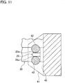
- the contact surface 43 is formed on a surface orthogonal to the clamping surface 41a. As illustrated in FIG. 11 , the contact surface 43 may be a plane parallel to the surface including the arrangement of the two protrusions 42.
- the female connector 20 is clamped by narrowing the distance between the pair of clamping portions 41.
- the protrusions 42 of the pair of clamping portions 41 contact the tapered surface 25a of the protrusion 25 provided on both side surfaces of the housing 22 (see FIG. 7(a) ).
- the pressing force from the protrusions 42 causes the contact surface 25b (see FIG. 7(c) ) of the housing 22 to contact the contact surface 43 of each clamping portion 41.
- the pair of clamping portions 41 clamp the housing 22 of the female connector 20 in a state where these abutments are maintained.
- the housing 22 of the female connector 20 is clamped (supported) in a state where the pair of clamping portions 41 of the gripper 40 is in contact with the female connector 20 at three or more points.
- This allows the female connector 20 to be firmly gripped.
- the fitting operation of the connectors can be performed reliably without causing displacement of the position and the angle (orientation) of the female connector 20 relative to the gripper 40.
- FIGs. 12(a) to 12C illustrate a third embodiment of the present disclosure.
- the third embodiment is different from the second embodiment only in the configuration of the female connector 20.
- the configuration of the pair of clamping portions 41 of the fitting device 30 is the same as that of the second embodiment.
- the female connector 20 includes a housing 22 and a holder 26 attached to cover the rear portion of the housing 22.
- a protrusion 25 for preventing misalignment is provided on both side surfaces of the holder 26.
- the protrusion 25 of the third embodiment is configured similarly to the protrusion 25 of the second embodiment, and the description thereof is not repeated.
- the same reference numbers are given to the same constituent components in the drawings.
- the form of the housing 22 of the female connector 20 is different from that of the second embodiment, and the form of the male connector (not illustrated) as the opponent connector is also different.
- the fitting device 30 is configured similarly to that of the second embodiment, and the description thereof is not repeated.
- the third embodiment can also reduce the burden to the operator who performs the connector fitting operation for the same reason as recited in the first embodiment.
- fitting device 30 according to the third embodiment can also grip the female connector 20 firmly for the same reason as recited the second embodiment.
- the protrusion 25 is provided on both side surfaces of the housing 22.
- the protrusion 25 for preventing misalignment is provided on both side surfaces of the holder 26.
- the above-described embodiments have described the fitting of the female connector 20 connected to the wire harness WH to the male connector 10 attached to the housing 2.
- the male connector 10 may not be attached to the housing 2, and the female connector 20 may not be connected to the wire harness WH.
- the present disclosure is applicable to fitting two connectors.
- the male connector 10 may be fitted to the female connector 20 which is fixed at a determined position and in a determined direction in the vehicle 1.
- the fitting device 30 may grip a male connector.
- the movable arm body 32 includes the device main body 33, the first arm 34, the second arm 35, and the third arm 36.
- the movable arm body 32 may be formed to move the gripper 40 to the arbitrary position in the three-dimensional space and in the arbitrary direction in the three-dimensional space.
- the above-described embodiments include the gripper 40 having the pair of clamping portions 41, but the gripper 40 may have other constituent components capable of gripping the connector.
Landscapes
- Engineering & Computer Science (AREA)
- Mechanical Engineering (AREA)
- Robotics (AREA)
- Manufacturing & Machinery (AREA)
- Details Of Connecting Devices For Male And Female Coupling (AREA)
- Manipulator (AREA)
- Manufacturing Of Electrical Connectors (AREA)
Abstract
Description
- The present disclosure relates to a connector fitting device for fitting a connector to an opponent connector.
- As illustrated in
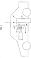
FIG. 13 , ahybrid vehicle 100 includes wire harnesses WH1 to WH3. The wire harnesses WH1 to WH3 electrically connect ajunction box 102, which is connected to abattery 101, with aninverter unit 103. The wire harness WH1 is connected to thejunction box 102. - The wire harness WH2 is connected to the
inverter unit 103. The wire harness WH3 electrically connects the wire harnesses WH1 and WH2. - Connections between a
connector 110 of thejunction box 102 and a connector of the wire harness WH1 (not illustrated), aconnector 111 of theinverter unit 103 and a connector of the wire harness WH2 (not illustrated), aconnector 112 of the wire harness WH1 and aconnector 113 of the wire harness WH3, and aconnector 114 of the wire harness WH2 and aconnector 115 of the wire harness WH3 are achieved by mate fitting. - Conventionally, an operator has made such mating connections of the connectors manually.
- A fitting operation of the connectors, however, is a burden to the operator, and there has been a need for reducing the burden.
- The present disclosure has been made to solve the above-described problem, and it is an object of the present disclosure to provide a connector fitting device that reduces a burden to an operator who performs a fitting operation the connectors.
- One aspect of the present disclosure is a connector fitting device for fitting a first connector to a second connector, including a movable arm body connected to a base on a base end side of the movable arm body, and a gripper connected to a distal end side of the movable arm body and capable of gripping the first connector, in which the connector fitting device configured to move the gripper to an arbitrary position in a three-dimensional space and in an arbitrary direction in the three-dimensional space.
- According to the present disclosure, the movable arm body moves the gripper to a connector feeding position, the gripper grips the connector, and the movable arm body moves the gripped connector to a fitting position to an opponent connector, whereby the movable arm body moves the connector in a fitting direction to the opponent connector for fitting. This eliminates the need for the operator to perform the fitting operation in person, and the operator only needs to operate the connector fitting device or set an automatic operation, thus reducing the burden to the operator.
-
-
FIG. 1 is a conceptual diagram for explaining connector fitting by a connector fitting device according to a first embodiment of the present disclosure; -
FIG. 2(a) is a perspective view illustrating a state in which a female connector is located at a feeding position with respect to a male connector in the first embodiment, andFIG. 2(b) is a perspective view illustrating a state in which the female connector is fitted to the male connector; -
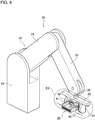
FIG. 3 is a perspective view of the connector fitting device according to the first embodiment; -
FIG. 4 is a perspective view of a state in which the connector fitting device according to the first embodiment grips the female connector; -
FIG. 5 is a perspective view illustrating a state in which the connector fitting device according to the first embodiment moves the female connector to a position facing a male connector and starts fitting to the male connector; -
FIG. 6 is a perspective view illustrating a state in which the connector fitting device according to the first embodiment has fitted the female connector to the male connector; -
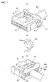
FIG. 7(a) is a perspective view of a female connector according to a second embodiment of the present disclosure when viewed from the front side,FIG. 7(b) is an enlarged view of a portion D1 inFIG. 7(a), and FIG. 7(c) is the perspective view of the female connector when viewed from the rear surface side; -
FIG. 8(a) is a perspective view of the connector fitting device according to the second embodiment, andFIG. 8(b) is an enlarged view of a portion D2 inFIG. 8(a) ; -
FIG. 9 is a perspective view of a state in which the connector fitting device grips the female connector according to the second embodiment; -
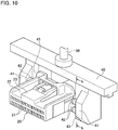
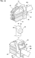
FIG. 10 is an enlarged view of a portion D3 inFIG. 9 ; -
FIG. 11 is a cross-sectional view taken along line bb ofFIG. 10 ; -
FIG. 12(a) is a perspective view of a female connector according to a third embodiment of the present disclosure when viewed from the front side,FIG. 12(b) is an enlarged view of a portion D4 inFIG. 12(a), and FIG. 12C is a perspective view of the female connector when viewed from the rear surface side; and -
FIG. 13 is a conceptual diagram of electrical connection using wire harnesses in a hybrid vehicle for explaining a conventional example. - Various embodiments will be described hereinafter with reference to the accompanying drawings.
- In the following detailed description, for purposes of explanation, numerous specific details are set forth in order to provide a thorough understanding of the disclosed embodiments. It will be apparent, however, that one or more embodiments may be practiced without these specific details. In other instances, well-known structures and devices are schematically shown in order to simplify the drawing.
- Description will be hereinbelow provided for embodiments of the present invention by referring to the drawings. It should be noted that the same or similar parts and components throughout the drawings will be denoted by the same or similar reference signs, and that descriptions for such parts and components will be omitted or simplified. In addition, it should be noted that the drawings are schematic and therefore different from the actual ones.
-
FIGs. 1 to 6 illustrate a first embodiment of the present disclosure. As illustrated inFIG. 1 , ahousing 2 for various sensors, an electronic control unit (ECU), and so on is mounted in the vehicle 1. Amale connector 10 serving as an opponent connector (second connector) is attached to thehousing 2. Themale connector 10 is fixed at a determined position and in a determined direction in the vehicle 1. A female connector (first connector) 20 connected to the terminal of a wire harness WH is fitted to themale connector 10, whereby the above-described sensors and the electronic control unit are connected to the system of the vehicle via a wire harness (cable) WH. - Thus, the
female connector 20 of the wire harness WH is fitted to themale connector 10 fixed at a determined position and in a determined direction in the vehicle 1 using a connector fitting device (hereinafter referred to as a fitting device) 30. Specifically, thefemale connector 20 connected to the wire harness WH is arranged at a feeding position as illustrated inFIG. 2(a) . Thefemale connector 20 is conveyed to the position of themale connector 10 fixed at the determined position and in the determined direction in the vehicle 1, and is fitted to themale connector 10 as illustrated inFIG. 2(b) . - First, the
male connector 10 and thefemale connector 20 are described. As illustrated inFIGs. 2(a) and 2(b) , themale connector 10 includes ahousing 12 having a connector fitting chamber (hereinafter referred to as a fitting chamber) 11, and a plurality of male terminals (not illustrated) arranged in a protruding manner in thefitting chamber 11 of thehousing 12. Thefitting chamber 11 has a substantially rectangular parallelepiped space, with one surface opened to the outside. Through this opening, thefemale connector 20 is inserted into and fitted to themale connector 10. An opponent housing lock (not illustrated) is provided in thefitting chamber 11. - The
female connector 20 includes ahousing 22 having a plurality ofterminal accommodating chambers 21 each having an open front surface, and female terminals (not illustrated) each accommodated in theterminal accommodating chambers 21. Thehousing 22 has a substantially rectangular parallelepiped shape. Ahousing lock 23 is provided on the upper surface of thehousing 22. A surface to be clamped 24 is formed at a rearward position of both side surfaces of thehousing 22. The surface to be clamped 24 is, for example, a flat surface and is clamped by a pair of clampingportions 41 of thefitting device 30 described below. The wire harness WH is connected to individual female terminals (not illustrated) and pulled out from the rear surface of thehousing 22. In other words, thefemale connector 20 is connected to the end of the wire harness WH. - Next, the
fitting device 30 is described. As illustrated inFIG. 3 , thefitting device 30 includes amovable arm body 32 connected to abase 31 on a base end side of themovable arm body 32, and agripper 40 connected to the distal end side (tip end side) of themovable arm body 32. - The
movable arm body 32 includes a devicemain body 33, afirst arm 34, asecond arm 35, and athird arm 36. The devicemain body 33 is provided on thebase 31. Further, the devicemain body 33 can rotate about an axis (first axis) C1. The axis (first axis) C1 is, for example, orthogonal to a horizontal plane. In this case, the devicemain body 33 rotates in the horizontal plane. Thefirst arm 34 is rotatably connected to the distal end portion (tip end portion) of the devicemain body 33. Thefirst arm 34 can rotate about an axis (second axis) C2. The axis (second axis) C2 is orthogonal to the axis (first axis) C1. For example, thefirst arm 34 rotates in a vertical plane which is orthogonal to the above-described horizontal plane. - The
second arm 35 is rotatably connected to the distal end portion of thefirst arm 34. Thesecond arm 35 can rotate about an axis (third axis) C3. The axis (third axis) C3 extends in the same direction as the axis (second axis) C2. That is, the axis (third axis) C3 is parallel to the axis (second axis) C2. Therefore, thesecond arm 35 can rotate in a plane in which thefirst arm 34 rotates. - The
third arm 36 is rotatably connected to the distal end portion of thesecond arm 35. Thethird arm 36 can rotate about an axis (fourth axis) C4. The axis (fourth axis) C4 extends in the same direction as the axis (second axis) C2. That is, the axis (fourth axis) C4 is parallel to the axis (second axis) C2. - The
gripper 40 is rotatably connected to the distal end portion of thethird arm 36. Thegripper 40 can rotate around the axis (fifth axis) C5. The axis (fifth axis) C5 extends in the same direction as the axis (first axis) C1. That is, the axis (fifth axis) C5 is parallel to the axis (first axis) C1. - In other words, a rotary joint is used to connect between the base 31 and the device
main body 33, the devicemain body 33 and thefirst arm 34, thefirst arm 34 and thesecond arm 35, thesecond arm 35 and thethird arm 36, and thethird arm 36 and thegripper 40. With such a configuration, thegripper 40 can be moved to an arbitrary position in the three-dimensional space and can be directed in an arbitrary direction in the three-dimensional space. Specifically, thegripper 40 is moved to an arbitrary position in the three-dimensional space by the rotation of the devicemain body 33, thefirst arm 34, and thesecond arm 35. By the rotation of thethird arm 36 and the rotation of thegripper 40 itself, thegripper 40 is directed in an arbitrary direction in the three-dimensional space. The same operation is possible if thesecond arm 35 and thethird arm 36 are connected by a ball joint and thegripper 40 is rigidly connected to thethird arm 36. - As illustrated in
FIG. 3 , thegripper 40 has a pair of clampingportions 41. The pair of clampingportions 41 are slidably provided so that a distance between the clampingportions 41 in the clamping direction (indicated by straight double arrows) can be adjusted. Each clampingportion 41 has aclamping surface 41a facing theopponent clamping portion 41. As will be described later, the clampingsurface 41a contacts the surface to be clamped 24 of thefemale connector 20 when thefemale connector 20 is clamped by thegripper 40. - Next, a connector fitting operation using the
fitting device 30 is described. Themovable arm body 32 moves thegripper 40 to a position at which thefemale connector 20 is fed and thehousing 22 of thefemale connector 20 can be clamped. Next, as illustrated inFIG. 4 , by narrowing the distance between the pair of clampingportions 41, the clampingsurface 41a comes into contact with the surface to be clamped 24 on both sides of thehousing 22 of thefemale connector 20 to grip thefemale connector 20. Then, themovable arm body 32 moves the grippedfemale connector 20 to a fitting start position facing themale connector 10 in the vicinity of the male connector 10 (seeFIG. 5 ). Next, as indicated by an arrow a inFIG. 5 , themovable arm body 32 moves thefemale connector 20 in the fitting direction, while adjusting the direction in a proper fitting direction to themale connector 10. By the operation of themovable arm body 32, thefemale connector 20 moves until thehousing lock 23 of thefemale connector 20 engages an opponent housing lock (not illustrated) of themale connector 10. As a result, thefemale connector 20 is fitted into themale connector 10 as illustrated inFIG. 6 . When the fitting of the connectors is completed, the distance between the pair of clampingportions 41 is widened to release clamping of thefemale connector 20 by the pair of clampingportions 41. Thus, the fitting operation is completed once. - As described above, the
fitting device 30 includes themovable arm body 32 connected to the base 31 on a base end side of the movable arm body, and thegripper 40 connected to the distal end side of themovable arm body 32 and capable of gripping thefemale connector 20, in which thegripper 40 is moved to the arbitrary position in the three-dimensional space and directed in the arbitrary direction in the three-dimensional space. In other words, thefitting device 30 includes thegripper 40 that can grip thefemale connector 20 and themovable arm body 32 that can change the three-dimensional position and the three-dimensional direction of thegripper 40. - Therefore, there is no need for the operator to move the
female connector 20 or perform the connector fitting operation in person. That is, the operator may operate or set automatic operation on thefitting device 30. Therefore, the present embodiment can reduce the burden to the operator in the connector fitting operation. -
FIGs. 7 to 11 illustrate a second embodiment of the present disclosure. The second embodiment differs from the first embodiment in the configuration of thefemale connector 20 and the configuration of the pair of clampingportions 41 of thefitting device 30. - Specifically, as illustrated in
FIGs. 7(a) to 7(c) , a protrusion (second protrusion) 25 for preventing misalignment is provided at a rearward position on both side surfaces of thehousing 22 of thefemale connector 20, that is, at a position clamped by the pair of clampingportions 41 of thefitting device 30. Eachprotrusion 25 is generally a delta cone-shaped protrusion. Eachprotrusion 25 has two taperedsurfaces 25a and acontact surface 25b arranged at the rear end of the twotapered surfaces 25a. The twotapered surfaces 25a and thecontact surface 25b constitute a conical surface of theprotrusion 25 having a shape similar to a delta cone. The twotapered surfaces 25a are inclined in opposite directions with respect to the vertical direction, and are inclined in opposite directions with respect to a lateral direction. Thecontact surface 25b is a flat surface extending in the vertical and lateral directions. Here, the vertical direction is a direction orthogonal to the fitting direction of thefemale connector 20 with respect to themale connector 10 and the clamping direction of the pair of clampingportions 41. Further, the lateral direction is the clamping direction of the pair of clampingportions 41. - As illustrated in
FIGs. 8(a) and 8(b) , each of the pair of clampingportions 41 has two protrusions (first protrusions) 42. The twoprotrusions 42 in each clampingportion 41 protrude toward theopponent clamping portion 41 and are spaced apart from each other in a predetermined direction. The predetermined direction is, for example, the vertical direction orthogonal to the fitting direction of thefemale connector 20 with respect to themale connector 10 and orthogonal to the clamping direction of the pair of clampingportions 41. Theprotrusions 42 are cylindrical rods. The tip end surface of eachprotrusion 42 is formed as a spherical surface which comes into contact with the opposing taperedsurface 25a when the pair of clampingportions 41 clamp thefemale connector 20. Each of the pair of clampingportions 41 has acontact surface 43. Thecontact surface 43 is arranged to the rearward of theprotrusions 42. Here, "rearward" refers to a position rearward of thefemale connector 20 in the fitting direction of thefemale connector 20. Thecontact surface 43 is formed on a surface orthogonal to theclamping surface 41a. As illustrated inFIG. 11 , thecontact surface 43 may be a plane parallel to the surface including the arrangement of the twoprotrusions 42. - Other constituent components are similar to those in the first embodiment, and the description thereof is not repeated. The same reference numbers are given to the same constituent components in the drawings.
- As illustrated in
FIGs. 9 and10 , thefemale connector 20 is clamped by narrowing the distance between the pair of clampingportions 41. When the clampingportions 41 clamp thefemale connector 20, theprotrusions 42 of the pair of clampingportions 41 contact thetapered surface 25a of theprotrusion 25 provided on both side surfaces of the housing 22 (seeFIG. 7(a) ). Further, the pressing force from theprotrusions 42 causes thecontact surface 25b (seeFIG. 7(c) ) of thehousing 22 to contact thecontact surface 43 of each clampingportion 41. The pair of clampingportions 41 clamp thehousing 22 of thefemale connector 20 in a state where these abutments are maintained. - Also in the second embodiment, for the same reason as in the first embodiment, the burden to the operator in the connector fitting operation can be reduced.
- As illustrated in
FIG. 11 , in the second embodiment, thehousing 22 of thefemale connector 20 is clamped (supported) in a state where the pair of clampingportions 41 of thegripper 40 is in contact with thefemale connector 20 at three or more points. This allows thefemale connector 20 to be firmly gripped. In other words, when thefemale connector 20 is fitted to themale connector 10 and even when the reaction force generated by the fitting operation acts on thegripper 40 from thefemale connector 20, the fitting operation of the connectors can be performed reliably without causing displacement of the position and the angle (orientation) of thefemale connector 20 relative to thegripper 40. -
FIGs. 12(a) to 12C illustrate a third embodiment of the present disclosure. The third embodiment is different from the second embodiment only in the configuration of thefemale connector 20. The configuration of the pair of clampingportions 41 of thefitting device 30 is the same as that of the second embodiment. - In the third embodiment, the
female connector 20 includes ahousing 22 and aholder 26 attached to cover the rear portion of thehousing 22. Aprotrusion 25 for preventing misalignment is provided on both side surfaces of theholder 26. Theprotrusion 25 of the third embodiment is configured similarly to theprotrusion 25 of the second embodiment, and the description thereof is not repeated. The same reference numbers are given to the same constituent components in the drawings. The form of thehousing 22 of thefemale connector 20 is different from that of the second embodiment, and the form of the male connector (not illustrated) as the opponent connector is also different. - The
fitting device 30 is configured similarly to that of the second embodiment, and the description thereof is not repeated. - The third embodiment can also reduce the burden to the operator who performs the connector fitting operation for the same reason as recited in the first embodiment.
- Further, the
fitting device 30 according to the third embodiment can also grip thefemale connector 20 firmly for the same reason as recited the second embodiment. - As in the second embodiment, when both side surfaces of the rear portion of the
housing 22 are exposed to the outside, theprotrusion 25 is provided on both side surfaces of thehousing 22. On the other hand, when both side surfaces of the rear portion of thehousing 22 are covered by theholder 26, as in the third embodiment, theprotrusion 25 for preventing misalignment is provided on both side surfaces of theholder 26. - The above-described embodiments have described the fitting of the
female connector 20 connected to the wire harness WH to themale connector 10 attached to thehousing 2. Alternatively, themale connector 10 may not be attached to thehousing 2, and thefemale connector 20 may not be connected to the wire harness WH. In other words, the present disclosure is applicable to fitting two connectors. - Further, the relationship between the
male connector 10 and thefemale connector 20 may be reversed. In other words, themale connector 10 may be fitted to thefemale connector 20 which is fixed at a determined position and in a determined direction in the vehicle 1. Thefitting device 30 may grip a male connector. - In the above-described embodiments, the
movable arm body 32 includes the devicemain body 33, thefirst arm 34, thesecond arm 35, and thethird arm 36. Alternatively, themovable arm body 32 may be formed to move thegripper 40 to the arbitrary position in the three-dimensional space and in the arbitrary direction in the three-dimensional space. - The above-described embodiments include the
gripper 40 having the pair of clampingportions 41, but thegripper 40 may have other constituent components capable of gripping the connector. - Embodiments of the present disclosure have been described above. However, the disclosure may be embodied in other specific forms without departing from the spirit or essential characteristics thereof. The present embodiments are therefore to be considered in all respects as illustrative and not restrictive, the scope of the invention being indicated by the appended claims rather than by the foregoing description and all changes, which come within the meaning and range of equivalency of the claims, are therefore intended to be embraced therein.
- Moreover, the effects described in the embodiments of the present disclosure are only a list of optimum effects achieved by the present invention. Hence, the effects of the present invention are not limited to those described in the embodiment of the present disclosure.
Claims (7)
- A connector fitting device for fitting a first connector to a second connector, comprising:a movable arm body connected to a base on a base end side of the movable arm body; anda gripper connected to a distal end side of the movable arm body and capable of gripping the first connector, whereinthe connector fitting device configured to move the gripper to an arbitrary position in a three-dimensional space and in an arbitrary direction in the three-dimensional space.
- The connector fitting device according to claim 1, wherein
the movable arm body includes
a device main body provided rotatably about a first axis on the base,
a first arm rotatably connected to the device main body about a second axis orthogonal to the first axis,
a second arm rotatably connected to a distal end portion of the first arm about a third axis extending in the same direction as the second axis, and
a third arm rotatably connected to a distal end portion of the second arm about a fourth axis extending in the same direction as the second axis, and
the gripper is rotatably connected to a distal end portion of the third arm about a fifth axis extending in the same direction as the first axis. - The connector fitting device according to claim 1 or 2, wherein
the gripper include a pair of clamping portions, and
the pair of clamping portions each include first two protrusions protruding toward an opponent clamping portion and arranged spaced apart from each other in a vertical direction, and a contact surface formed rearward of the first two protrusions. - The connector fitting device according to claim 3, wherein
the contact surface is a plane parallel to a surface including an arrangement of the first two protrusions. - The connector fitting device according to claim 3 or 4, wherein
each of the first protrusions has a spherical tip end surface. - The connector fitting device according to any one of claims 3 to 5, wherein
the first connector has a second protrusion protruding from both side surfaces of the first connector,
the second protrusion includes two tapered surfaces inclined in opposite directions with respect to a vertical direction and inclined in opposite directions with respect to a lateral direction, and a contact surface arranged at a rear end of the two tapered surfaces, and
the pair of clamping portions is configured to grip the first connector in a state where the first two protrusions contact both of the tapered surfaces of the first connector and the contact surface of the first connector contacts each of the two contact surfaces of the pair of clamping portions by pressing force of the first two protrusions. - The connector fitting device according to claim 6, wherein
when both of side surfaces of a rear portion of a housing of the first connector are exposed to the outside, the second protrusion is provided on both side surfaces of the housing, and
when a holder covers both side surfaces of the rear side of the housing, the second protrusion is provided on both side surfaces of the holder.
Applications Claiming Priority (1)
| Application Number | Priority Date | Filing Date | Title |
|---|---|---|---|
| JP2019013946A JP6868651B2 (en) | 2019-01-30 | 2019-01-30 | Connector mating device |
Publications (2)
| Publication Number | Publication Date |
|---|---|
| EP3691055A1 true EP3691055A1 (en) | 2020-08-05 |
| EP3691055B1 EP3691055B1 (en) | 2022-03-23 |
Family
ID=69185486
Family Applications (1)
| Application Number | Title | Priority Date | Filing Date |
|---|---|---|---|
| EP20152845.2A Active EP3691055B1 (en) | 2019-01-30 | 2020-01-21 | Connector fitting device |
Country Status (4)
| Country | Link |
|---|---|
| US (1) | US11417996B2 (en) |
| EP (1) | EP3691055B1 (en) |
| JP (1) | JP6868651B2 (en) |
| CN (1) | CN111509526B (en) |
Cited By (1)
| Publication number | Priority date | Publication date | Assignee | Title |
|---|---|---|---|---|
| DE102022103503A1 (en) | 2022-02-15 | 2023-08-17 | WAGO Verwaltungsgesellschaft mit beschränkter Haftung | Process, robot system and computer program for the automated assembly of components on mounting rails |
Families Citing this family (3)
| Publication number | Priority date | Publication date | Assignee | Title |
|---|---|---|---|---|
| DE102020210287B4 (en) | 2020-08-13 | 2023-02-02 | Volkswagen Aktiengesellschaft | Electrical contact system |
| DE102023210027A1 (en) * | 2023-10-12 | 2025-04-17 | Volkswagen Aktiengesellschaft | Method, process arrangement and connector for the automated handling of a cable harness |
| WO2026057842A1 (en) * | 2024-09-16 | 2026-03-19 | Limacorporate S.P.A. | Gripping device for a mechanical component, gripping method and corresponding gripping kit |
Citations (4)
| Publication number | Priority date | Publication date | Assignee | Title |
|---|---|---|---|---|
| US20130076902A1 (en) * | 2011-09-26 | 2013-03-28 | Universite Laval | Robotically operated vehicle charging station |
| EP3012073A1 (en) * | 2014-10-22 | 2016-04-27 | Seiko Epson Corporation | Robot |
| EP3064324A1 (en) * | 2015-03-02 | 2016-09-07 | Kabushiki Kaisha Yaskawa Denki | Robot |
| WO2017178924A1 (en) * | 2016-04-13 | 2017-10-19 | Tyco Electronics (Shanghai) Co. Ltd. | Robot assembling system and robot assembling method for connector assembly |
Family Cites Families (24)
| Publication number | Priority date | Publication date | Assignee | Title |
|---|---|---|---|---|
| US3139302A (en) * | 1961-09-08 | 1964-06-30 | Molins Machine Co Ltd | Mechanical handling apparatus |
| US4042122A (en) * | 1975-05-27 | 1977-08-16 | The Bendix Corporation | Reorientation device for an object manipulator |
| DE3340614C1 (en) * | 1983-11-10 | 1985-02-21 | Daimler-Benz Ag, 7000 Stuttgart | Device for painting series parts with changing colors |
| JPS60229109A (en) * | 1984-04-27 | 1985-11-14 | Hitachi Ltd | Position correcting system using visual camera |
| JPS6135776U (en) * | 1984-08-08 | 1986-03-05 | 三菱電機株式会社 | robot |
| US4647100A (en) * | 1985-07-25 | 1987-03-03 | Arobotech Systems, Inc. | Parallel gripper with roller supported gripper arms |
| JPH074787B2 (en) * | 1986-06-04 | 1995-01-25 | 株式会社日立製作所 | Gripping device |
| JPH0450302Y2 (en) * | 1987-01-08 | 1992-11-26 | ||
| IT1231427B (en) * | 1987-10-08 | 1991-12-04 | Civiemme Srl | CLAMP PALLETIZER FOR THE GRAPHIC INDUSTRY |
| JPH0639912Y2 (en) * | 1990-11-30 | 1994-10-19 | エンケイ株式会社 | Robot hand wheel gripping claw |
| US5494325A (en) * | 1993-08-24 | 1996-02-27 | Canadian Space Agency | Article converging/diverging, chamfered walls gripping anvils |
| JP3638162B2 (en) * | 1995-09-29 | 2005-04-13 | 沖電気工業株式会社 | Automatic insertion / removal robot for main wiring board connection pins |
| JP4441615B2 (en) * | 2005-06-09 | 2010-03-31 | 独立行政法人産業技術総合研究所 | Robot arm control device for inserting 3-pin plug for power supply |
| JP5448326B2 (en) * | 2007-10-29 | 2014-03-19 | キヤノン株式会社 | Gripping device and gripping device control method |
| CH705297A1 (en) * | 2011-07-21 | 2013-01-31 | Tecan Trading Ag | Gripping pliers with interchangeable gripper fingers. |
| JP6400321B2 (en) * | 2014-03-31 | 2018-10-03 | 本田技研工業株式会社 | Work holding method |
| JP2015223649A (en) * | 2014-05-27 | 2015-12-14 | 株式会社安川電機 | Gear incorporating system and gear incorporating method |
| JP2016043455A (en) * | 2014-08-25 | 2016-04-04 | セイコーエプソン株式会社 | Robot and robot system |
| JP2018007378A (en) | 2016-06-30 | 2018-01-11 | 矢崎総業株式会社 | Wiring harness |
| JP6915239B2 (en) * | 2016-07-22 | 2021-08-04 | セイコーエプソン株式会社 | Insertion method |
| JP6506245B2 (en) * | 2016-12-26 | 2019-04-24 | ファナック株式会社 | Machine learning apparatus and part assembling system for learning assembling operation |
| CN106826883B (en) * | 2017-02-25 | 2024-06-21 | 中信戴卡股份有限公司 | Grabbing hub is with self-adjusting robot clamping jaw |
| JP6718583B2 (en) * | 2017-05-18 | 2020-07-08 | Smc株式会社 | Work gripping device |
| CN208539319U (en) * | 2018-05-29 | 2019-02-22 | 宁波图锐自动化设备有限公司 | It is a kind of for liquid crystal display connector to the angle adjusting mechanism of plug in machine |
-
2019
- 2019-01-30 JP JP2019013946A patent/JP6868651B2/en active Active
-
2020
- 2020-01-19 CN CN202010059357.2A patent/CN111509526B/en active Active
- 2020-01-21 EP EP20152845.2A patent/EP3691055B1/en active Active
- 2020-01-29 US US16/775,674 patent/US11417996B2/en active Active
Patent Citations (4)
| Publication number | Priority date | Publication date | Assignee | Title |
|---|---|---|---|---|
| US20130076902A1 (en) * | 2011-09-26 | 2013-03-28 | Universite Laval | Robotically operated vehicle charging station |
| EP3012073A1 (en) * | 2014-10-22 | 2016-04-27 | Seiko Epson Corporation | Robot |
| EP3064324A1 (en) * | 2015-03-02 | 2016-09-07 | Kabushiki Kaisha Yaskawa Denki | Robot |
| WO2017178924A1 (en) * | 2016-04-13 | 2017-10-19 | Tyco Electronics (Shanghai) Co. Ltd. | Robot assembling system and robot assembling method for connector assembly |
Cited By (1)
| Publication number | Priority date | Publication date | Assignee | Title |
|---|---|---|---|---|
| DE102022103503A1 (en) | 2022-02-15 | 2023-08-17 | WAGO Verwaltungsgesellschaft mit beschränkter Haftung | Process, robot system and computer program for the automated assembly of components on mounting rails |
Also Published As
| Publication number | Publication date |
|---|---|
| EP3691055B1 (en) | 2022-03-23 |
| CN111509526B (en) | 2021-10-22 |
| JP2020121361A (en) | 2020-08-13 |
| US20200244026A1 (en) | 2020-07-30 |
| CN111509526A (en) | 2020-08-07 |
| US11417996B2 (en) | 2022-08-16 |
| JP6868651B2 (en) | 2021-05-12 |
Similar Documents
| Publication | Publication Date | Title |
|---|---|---|
| EP3691055B1 (en) | Connector fitting device | |
| JP6664425B2 (en) | Electrical connector with terminal position assurance device | |
| EP2790273A1 (en) | Electrical connector system connectable in a straight or right angle configuration | |
| CN113785449A (en) | Socket connector for charging port assembly | |
| KR20190033086A (en) | Power terminals for electrical connectors | |
| CN103828134B (en) | electrical connector | |
| US9246260B2 (en) | Electrical connector | |
| CN109638562A (en) | Electric connector system with cooperation guide features | |
| US20020177348A1 (en) | Power feeding connector apparatus | |
| EP2811586A1 (en) | Connector device | |
| CN103430396A (en) | High Voltage Connector Assembly | |
| JP4658429B2 (en) | Improvement of flexible circuit connection device | |
| JPH11260481A (en) | Electrical connector with latch | |
| US11005215B2 (en) | Connector and connector assembly | |
| JP2023033402A (en) | connector | |
| US11812576B2 (en) | Socket connector for a power connector system | |
| US20240313458A1 (en) | Reliable high speed connector | |
| US5504990A (en) | Device for connecting connection elements into connectors | |
| CN108352656B (en) | connector device | |
| JP7044816B2 (en) | Wire straightening method and wire straightening device | |
| JP2000223198A (en) | Electrical connector | |
| CN119895667A (en) | Supply charging device comprising a supply power connector | |
| US20180358747A1 (en) | Electrical connection device | |
| US20100130052A1 (en) | Electrical connector | |
| JPH07235343A (en) | connector |
Legal Events
| Date | Code | Title | Description |
|---|---|---|---|
| PUAI | Public reference made under article 153(3) epc to a published international application that has entered the european phase |
Free format text: ORIGINAL CODE: 0009012 |
|
| STAA | Information on the status of an ep patent application or granted ep patent |
Free format text: STATUS: REQUEST FOR EXAMINATION WAS MADE |
|
| 17P | Request for examination filed |
Effective date: 20200121 |
|
| AK | Designated contracting states |
Kind code of ref document: A1 Designated state(s): AL AT BE BG CH CY CZ DE DK EE ES FI FR GB GR HR HU IE IS IT LI LT LU LV MC MK MT NL NO PL PT RO RS SE SI SK SM TR |
|
| AX | Request for extension of the european patent |
Extension state: BA ME |
|
| RBV | Designated contracting states (corrected) |
Designated state(s): AL AT BE BG CH CY CZ DE DK EE ES FI FR GB GR HR HU IE IS IT LI LT LU LV MC MK MT NL NO PL PT RO RS SE SI SK SM TR |
|
| RIC1 | Information provided on ipc code assigned before grant |
Ipc: H01R 107/00 20060101ALN20210831BHEP Ipc: H01R 13/516 20060101ALN20210831BHEP Ipc: B25J 15/02 20060101ALI20210831BHEP Ipc: B25J 15/00 20060101ALI20210831BHEP Ipc: B25J 9/04 20060101ALI20210831BHEP Ipc: H01R 43/26 20060101AFI20210831BHEP |
|
| GRAP | Despatch of communication of intention to grant a patent |
Free format text: ORIGINAL CODE: EPIDOSNIGR1 |
|
| STAA | Information on the status of an ep patent application or granted ep patent |
Free format text: STATUS: GRANT OF PATENT IS INTENDED |
|
| RIC1 | Information provided on ipc code assigned before grant |
Ipc: H01R 107/00 20060101ALN20210921BHEP Ipc: H01R 13/516 20060101ALN20210921BHEP Ipc: B25J 15/02 20060101ALI20210921BHEP Ipc: B25J 15/00 20060101ALI20210921BHEP Ipc: B25J 9/04 20060101ALI20210921BHEP Ipc: H01R 43/26 20060101AFI20210921BHEP |
|
| RIC1 | Information provided on ipc code assigned before grant |
Ipc: H01R 107/00 20060101ALN20210929BHEP Ipc: H01R 13/516 20060101ALN20210929BHEP Ipc: B25J 15/02 20060101ALI20210929BHEP Ipc: B25J 15/00 20060101ALI20210929BHEP Ipc: B25J 9/04 20060101ALI20210929BHEP Ipc: H01R 43/26 20060101AFI20210929BHEP |
|
| INTG | Intention to grant announced |
Effective date: 20211022 |
|
| GRAJ | Information related to disapproval of communication of intention to grant by the applicant or resumption of examination proceedings by the epo deleted |
Free format text: ORIGINAL CODE: EPIDOSDIGR1 |
|
| STAA | Information on the status of an ep patent application or granted ep patent |
Free format text: STATUS: REQUEST FOR EXAMINATION WAS MADE |
|
| INTC | Intention to grant announced (deleted) | ||
| GRAP | Despatch of communication of intention to grant a patent |
Free format text: ORIGINAL CODE: EPIDOSNIGR1 |
|
| STAA | Information on the status of an ep patent application or granted ep patent |
Free format text: STATUS: GRANT OF PATENT IS INTENDED |
|
| RIC1 | Information provided on ipc code assigned before grant |
Ipc: H01R 107/00 20060101ALN20211217BHEP Ipc: H01R 13/516 20060101ALN20211217BHEP Ipc: B25J 15/02 20060101ALI20211217BHEP Ipc: B25J 15/00 20060101ALI20211217BHEP Ipc: B25J 9/04 20060101ALI20211217BHEP Ipc: H01R 43/26 20060101AFI20211217BHEP |
|
| GRAS | Grant fee paid |
Free format text: ORIGINAL CODE: EPIDOSNIGR3 |
|
| INTG | Intention to grant announced |
Effective date: 20220119 |
|
| GRAA | (expected) grant |
Free format text: ORIGINAL CODE: 0009210 |
|
| STAA | Information on the status of an ep patent application or granted ep patent |
Free format text: STATUS: THE PATENT HAS BEEN GRANTED |
|
| AK | Designated contracting states |
Kind code of ref document: B1 Designated state(s): AL AT BE BG CH CY CZ DE DK EE ES FI FR GB GR HR HU IE IS IT LI LT LU LV MC MK MT NL NO PL PT RO RS SE SI SK SM TR |
|
| REG | Reference to a national code |
Ref country code: GB Ref legal event code: FG4D |
|
| REG | Reference to a national code |
Ref country code: CH Ref legal event code: EP |
|
| REG | Reference to a national code |
Ref country code: DE Ref legal event code: R096 Ref document number: 602020002263 Country of ref document: DE |
|
| REG | Reference to a national code |
Ref country code: IE Ref legal event code: FG4D |
|
| REG | Reference to a national code |
Ref country code: AT Ref legal event code: REF Ref document number: 1478098 Country of ref document: AT Kind code of ref document: T Effective date: 20220415 |
|
| REG | Reference to a national code |
Ref country code: LT Ref legal event code: MG9D |
|
| REG | Reference to a national code |
Ref country code: NL Ref legal event code: MP Effective date: 20220323 |
|
| PG25 | Lapsed in a contracting state [announced via postgrant information from national office to epo] |
Ref country code: SE Free format text: LAPSE BECAUSE OF FAILURE TO SUBMIT A TRANSLATION OF THE DESCRIPTION OR TO PAY THE FEE WITHIN THE PRESCRIBED TIME-LIMIT Effective date: 20220323 Ref country code: RS Free format text: LAPSE BECAUSE OF FAILURE TO SUBMIT A TRANSLATION OF THE DESCRIPTION OR TO PAY THE FEE WITHIN THE PRESCRIBED TIME-LIMIT Effective date: 20220323 Ref country code: NO Free format text: LAPSE BECAUSE OF FAILURE TO SUBMIT A TRANSLATION OF THE DESCRIPTION OR TO PAY THE FEE WITHIN THE PRESCRIBED TIME-LIMIT Effective date: 20220623 Ref country code: LT Free format text: LAPSE BECAUSE OF FAILURE TO SUBMIT A TRANSLATION OF THE DESCRIPTION OR TO PAY THE FEE WITHIN THE PRESCRIBED TIME-LIMIT Effective date: 20220323 Ref country code: HR Free format text: LAPSE BECAUSE OF FAILURE TO SUBMIT A TRANSLATION OF THE DESCRIPTION OR TO PAY THE FEE WITHIN THE PRESCRIBED TIME-LIMIT Effective date: 20220323 Ref country code: BG Free format text: LAPSE BECAUSE OF FAILURE TO SUBMIT A TRANSLATION OF THE DESCRIPTION OR TO PAY THE FEE WITHIN THE PRESCRIBED TIME-LIMIT Effective date: 20220623 |
|
| REG | Reference to a national code |
Ref country code: AT Ref legal event code: MK05 Ref document number: 1478098 Country of ref document: AT Kind code of ref document: T Effective date: 20220323 |
|
| PG25 | Lapsed in a contracting state [announced via postgrant information from national office to epo] |
Ref country code: LV Free format text: LAPSE BECAUSE OF FAILURE TO SUBMIT A TRANSLATION OF THE DESCRIPTION OR TO PAY THE FEE WITHIN THE PRESCRIBED TIME-LIMIT Effective date: 20220323 Ref country code: GR Free format text: LAPSE BECAUSE OF FAILURE TO SUBMIT A TRANSLATION OF THE DESCRIPTION OR TO PAY THE FEE WITHIN THE PRESCRIBED TIME-LIMIT Effective date: 20220624 Ref country code: FI Free format text: LAPSE BECAUSE OF FAILURE TO SUBMIT A TRANSLATION OF THE DESCRIPTION OR TO PAY THE FEE WITHIN THE PRESCRIBED TIME-LIMIT Effective date: 20220323 |
|
| PG25 | Lapsed in a contracting state [announced via postgrant information from national office to epo] |
Ref country code: NL Free format text: LAPSE BECAUSE OF FAILURE TO SUBMIT A TRANSLATION OF THE DESCRIPTION OR TO PAY THE FEE WITHIN THE PRESCRIBED TIME-LIMIT Effective date: 20220323 |
|
| PG25 | Lapsed in a contracting state [announced via postgrant information from national office to epo] |
Ref country code: SM Free format text: LAPSE BECAUSE OF FAILURE TO SUBMIT A TRANSLATION OF THE DESCRIPTION OR TO PAY THE FEE WITHIN THE PRESCRIBED TIME-LIMIT Effective date: 20220323 Ref country code: SK Free format text: LAPSE BECAUSE OF FAILURE TO SUBMIT A TRANSLATION OF THE DESCRIPTION OR TO PAY THE FEE WITHIN THE PRESCRIBED TIME-LIMIT Effective date: 20220323 Ref country code: RO Free format text: LAPSE BECAUSE OF FAILURE TO SUBMIT A TRANSLATION OF THE DESCRIPTION OR TO PAY THE FEE WITHIN THE PRESCRIBED TIME-LIMIT Effective date: 20220323 Ref country code: PT Free format text: LAPSE BECAUSE OF FAILURE TO SUBMIT A TRANSLATION OF THE DESCRIPTION OR TO PAY THE FEE WITHIN THE PRESCRIBED TIME-LIMIT Effective date: 20220725 Ref country code: ES Free format text: LAPSE BECAUSE OF FAILURE TO SUBMIT A TRANSLATION OF THE DESCRIPTION OR TO PAY THE FEE WITHIN THE PRESCRIBED TIME-LIMIT Effective date: 20220323 Ref country code: EE Free format text: LAPSE BECAUSE OF FAILURE TO SUBMIT A TRANSLATION OF THE DESCRIPTION OR TO PAY THE FEE WITHIN THE PRESCRIBED TIME-LIMIT Effective date: 20220323 Ref country code: CZ Free format text: LAPSE BECAUSE OF FAILURE TO SUBMIT A TRANSLATION OF THE DESCRIPTION OR TO PAY THE FEE WITHIN THE PRESCRIBED TIME-LIMIT Effective date: 20220323 Ref country code: AT Free format text: LAPSE BECAUSE OF FAILURE TO SUBMIT A TRANSLATION OF THE DESCRIPTION OR TO PAY THE FEE WITHIN THE PRESCRIBED TIME-LIMIT Effective date: 20220323 |
|
| PG25 | Lapsed in a contracting state [announced via postgrant information from national office to epo] |
Ref country code: PL Free format text: LAPSE BECAUSE OF FAILURE TO SUBMIT A TRANSLATION OF THE DESCRIPTION OR TO PAY THE FEE WITHIN THE PRESCRIBED TIME-LIMIT Effective date: 20220323 Ref country code: IS Free format text: LAPSE BECAUSE OF FAILURE TO SUBMIT A TRANSLATION OF THE DESCRIPTION OR TO PAY THE FEE WITHIN THE PRESCRIBED TIME-LIMIT Effective date: 20220723 Ref country code: AL Free format text: LAPSE BECAUSE OF FAILURE TO SUBMIT A TRANSLATION OF THE DESCRIPTION OR TO PAY THE FEE WITHIN THE PRESCRIBED TIME-LIMIT Effective date: 20220323 |
|
| REG | Reference to a national code |
Ref country code: DE Ref legal event code: R097 Ref document number: 602020002263 Country of ref document: DE |
|
| PLBE | No opposition filed within time limit |
Free format text: ORIGINAL CODE: 0009261 |
|
| STAA | Information on the status of an ep patent application or granted ep patent |
Free format text: STATUS: NO OPPOSITION FILED WITHIN TIME LIMIT |
|
| PG25 | Lapsed in a contracting state [announced via postgrant information from national office to epo] |
Ref country code: DK Free format text: LAPSE BECAUSE OF FAILURE TO SUBMIT A TRANSLATION OF THE DESCRIPTION OR TO PAY THE FEE WITHIN THE PRESCRIBED TIME-LIMIT Effective date: 20220323 |
|
| 26N | No opposition filed |
Effective date: 20230102 |
|
| PG25 | Lapsed in a contracting state [announced via postgrant information from national office to epo] |
Ref country code: SI Free format text: LAPSE BECAUSE OF FAILURE TO SUBMIT A TRANSLATION OF THE DESCRIPTION OR TO PAY THE FEE WITHIN THE PRESCRIBED TIME-LIMIT Effective date: 20220323 |
|
| PG25 | Lapsed in a contracting state [announced via postgrant information from national office to epo] |
Ref country code: IT Free format text: LAPSE BECAUSE OF FAILURE TO SUBMIT A TRANSLATION OF THE DESCRIPTION OR TO PAY THE FEE WITHIN THE PRESCRIBED TIME-LIMIT Effective date: 20220323 |
|
| REG | Reference to a national code |
Ref country code: CH Ref legal event code: PL |
|
| PG25 | Lapsed in a contracting state [announced via postgrant information from national office to epo] |
Ref country code: LU Free format text: LAPSE BECAUSE OF NON-PAYMENT OF DUE FEES Effective date: 20230121 |
|
| REG | Reference to a national code |
Ref country code: BE Ref legal event code: MM Effective date: 20230131 |
|
| PG25 | Lapsed in a contracting state [announced via postgrant information from national office to epo] |
Ref country code: LI Free format text: LAPSE BECAUSE OF NON-PAYMENT OF DUE FEES Effective date: 20230131 Ref country code: CH Free format text: LAPSE BECAUSE OF NON-PAYMENT OF DUE FEES Effective date: 20230131 |
|
| PG25 | Lapsed in a contracting state [announced via postgrant information from national office to epo] |
Ref country code: FR Free format text: LAPSE BECAUSE OF NON-PAYMENT OF DUE FEES Effective date: 20230131 Ref country code: BE Free format text: LAPSE BECAUSE OF NON-PAYMENT OF DUE FEES Effective date: 20230131 |
|
| PG25 | Lapsed in a contracting state [announced via postgrant information from national office to epo] |
Ref country code: IE Free format text: LAPSE BECAUSE OF NON-PAYMENT OF DUE FEES Effective date: 20230121 |
|
| PG25 | Lapsed in a contracting state [announced via postgrant information from national office to epo] |
Ref country code: MC Free format text: LAPSE BECAUSE OF FAILURE TO SUBMIT A TRANSLATION OF THE DESCRIPTION OR TO PAY THE FEE WITHIN THE PRESCRIBED TIME-LIMIT Effective date: 20220323 |
|
| PG25 | Lapsed in a contracting state [announced via postgrant information from national office to epo] |
Ref country code: MC Free format text: LAPSE BECAUSE OF FAILURE TO SUBMIT A TRANSLATION OF THE DESCRIPTION OR TO PAY THE FEE WITHIN THE PRESCRIBED TIME-LIMIT Effective date: 20220323 |
|
| GBPC | Gb: european patent ceased through non-payment of renewal fee |
Effective date: 20240121 |
|
| PG25 | Lapsed in a contracting state [announced via postgrant information from national office to epo] |
Ref country code: GB Free format text: LAPSE BECAUSE OF NON-PAYMENT OF DUE FEES Effective date: 20240121 |
|
| PG25 | Lapsed in a contracting state [announced via postgrant information from national office to epo] |
Ref country code: GB Free format text: LAPSE BECAUSE OF NON-PAYMENT OF DUE FEES Effective date: 20240121 |
|
| PG25 | Lapsed in a contracting state [announced via postgrant information from national office to epo] |
Ref country code: CY Free format text: LAPSE BECAUSE OF FAILURE TO SUBMIT A TRANSLATION OF THE DESCRIPTION OR TO PAY THE FEE WITHIN THE PRESCRIBED TIME-LIMIT; INVALID AB INITIO Effective date: 20200121 |
|
| PG25 | Lapsed in a contracting state [announced via postgrant information from national office to epo] |
Ref country code: HU Free format text: LAPSE BECAUSE OF FAILURE TO SUBMIT A TRANSLATION OF THE DESCRIPTION OR TO PAY THE FEE WITHIN THE PRESCRIBED TIME-LIMIT; INVALID AB INITIO Effective date: 20200121 |
|
| PG25 | Lapsed in a contracting state [announced via postgrant information from national office to epo] |
Ref country code: TR Free format text: LAPSE BECAUSE OF FAILURE TO SUBMIT A TRANSLATION OF THE DESCRIPTION OR TO PAY THE FEE WITHIN THE PRESCRIBED TIME-LIMIT Effective date: 20220323 |
|
| PGFP | Annual fee paid to national office [announced via postgrant information from national office to epo] |
Ref country code: DE Payment date: 20251203 Year of fee payment: 7 |