EP3691021A1 - Electrode assembly, and secondary battery and battery pack including same - Google Patents
Electrode assembly, and secondary battery and battery pack including same Download PDFInfo
- Publication number
- EP3691021A1 EP3691021A1 EP19868935.8A EP19868935A EP3691021A1 EP 3691021 A1 EP3691021 A1 EP 3691021A1 EP 19868935 A EP19868935 A EP 19868935A EP 3691021 A1 EP3691021 A1 EP 3691021A1
- Authority
- EP
- European Patent Office
- Prior art keywords
- safety plate
- semiconductor material
- safety
- radical unit
- unit
- Prior art date
- Legal status (The legal status is an assumption and is not a legal conclusion. Google has not performed a legal analysis and makes no representation as to the accuracy of the status listed.)
- Pending
Links
Images



Classifications
-
- H—ELECTRICITY
- H01—ELECTRIC ELEMENTS
- H01M—PROCESSES OR MEANS, e.g. BATTERIES, FOR THE DIRECT CONVERSION OF CHEMICAL ENERGY INTO ELECTRICAL ENERGY
- H01M10/00—Secondary cells; Manufacture thereof
- H01M10/04—Construction or manufacture in general
- H01M10/0436—Small-sized flat cells or batteries for portable equipment
-
- H—ELECTRICITY
- H01—ELECTRIC ELEMENTS
- H01M—PROCESSES OR MEANS, e.g. BATTERIES, FOR THE DIRECT CONVERSION OF CHEMICAL ENERGY INTO ELECTRICAL ENERGY
- H01M10/00—Secondary cells; Manufacture thereof
- H01M10/60—Heating or cooling; Temperature control
- H01M10/61—Types of temperature control
- H01M10/613—Cooling or keeping cold
-
- H—ELECTRICITY
- H01—ELECTRIC ELEMENTS
- H01M—PROCESSES OR MEANS, e.g. BATTERIES, FOR THE DIRECT CONVERSION OF CHEMICAL ENERGY INTO ELECTRICAL ENERGY
- H01M10/00—Secondary cells; Manufacture thereof
- H01M10/60—Heating or cooling; Temperature control
- H01M10/62—Heating or cooling; Temperature control specially adapted for specific applications
- H01M10/623—Portable devices, e.g. mobile telephones, cameras or pacemakers
-
- H—ELECTRICITY
- H01—ELECTRIC ELEMENTS
- H01M—PROCESSES OR MEANS, e.g. BATTERIES, FOR THE DIRECT CONVERSION OF CHEMICAL ENERGY INTO ELECTRICAL ENERGY
- H01M10/00—Secondary cells; Manufacture thereof
- H01M10/60—Heating or cooling; Temperature control
- H01M10/63—Control systems
- H01M10/637—Control systems characterised by the use of reversible temperature-sensitive devices, e.g. NTC, PTC or bimetal devices; characterised by control of the internal current flowing through the cells, e.g. by switching
-
- H—ELECTRICITY
- H01—ELECTRIC ELEMENTS
- H01M—PROCESSES OR MEANS, e.g. BATTERIES, FOR THE DIRECT CONVERSION OF CHEMICAL ENERGY INTO ELECTRICAL ENERGY
- H01M10/00—Secondary cells; Manufacture thereof
- H01M10/60—Heating or cooling; Temperature control
- H01M10/64—Heating or cooling; Temperature control characterised by the shape of the cells
- H01M10/647—Prismatic or flat cells, e.g. pouch cells
-
- H—ELECTRICITY
- H01—ELECTRIC ELEMENTS
- H01M—PROCESSES OR MEANS, e.g. BATTERIES, FOR THE DIRECT CONVERSION OF CHEMICAL ENERGY INTO ELECTRICAL ENERGY
- H01M10/00—Secondary cells; Manufacture thereof
- H01M10/60—Heating or cooling; Temperature control
- H01M10/65—Means for temperature control structurally associated with the cells
- H01M10/654—Means for temperature control structurally associated with the cells located inside the innermost case of the cells, e.g. mandrels, electrodes or electrolytes
-
- H—ELECTRICITY
- H01—ELECTRIC ELEMENTS
- H01M—PROCESSES OR MEANS, e.g. BATTERIES, FOR THE DIRECT CONVERSION OF CHEMICAL ENERGY INTO ELECTRICAL ENERGY
- H01M10/00—Secondary cells; Manufacture thereof
- H01M10/60—Heating or cooling; Temperature control
- H01M10/65—Means for temperature control structurally associated with the cells
- H01M10/658—Means for temperature control structurally associated with the cells by thermal insulation or shielding
-
- H—ELECTRICITY
- H01—ELECTRIC ELEMENTS
- H01M—PROCESSES OR MEANS, e.g. BATTERIES, FOR THE DIRECT CONVERSION OF CHEMICAL ENERGY INTO ELECTRICAL ENERGY
- H01M50/00—Constructional details or processes of manufacture of the non-active parts of electrochemical cells other than fuel cells, e.g. hybrid cells
- H01M50/20—Mountings; Secondary casings or frames; Racks, modules or packs; Suspension devices; Shock absorbers; Transport or carrying devices; Holders
-
- H—ELECTRICITY
- H01—ELECTRIC ELEMENTS
- H01M—PROCESSES OR MEANS, e.g. BATTERIES, FOR THE DIRECT CONVERSION OF CHEMICAL ENERGY INTO ELECTRICAL ENERGY
- H01M50/00—Constructional details or processes of manufacture of the non-active parts of electrochemical cells other than fuel cells, e.g. hybrid cells
- H01M50/50—Current conducting connections for cells or batteries
- H01M50/572—Means for preventing undesired use or discharge
- H01M50/574—Devices or arrangements for the interruption of current
- H01M50/581—Devices or arrangements for the interruption of current in response to temperature
-
- H—ELECTRICITY
- H01—ELECTRIC ELEMENTS
- H01M—PROCESSES OR MEANS, e.g. BATTERIES, FOR THE DIRECT CONVERSION OF CHEMICAL ENERGY INTO ELECTRICAL ENERGY
- H01M50/00—Constructional details or processes of manufacture of the non-active parts of electrochemical cells other than fuel cells, e.g. hybrid cells
- H01M50/50—Current conducting connections for cells or batteries
- H01M50/572—Means for preventing undesired use or discharge
- H01M50/584—Means for preventing undesired use or discharge for preventing incorrect connections inside or outside the batteries
- H01M50/586—Means for preventing undesired use or discharge for preventing incorrect connections inside or outside the batteries inside the batteries, e.g. incorrect connections of electrodes
-
- H—ELECTRICITY
- H01—ELECTRIC ELEMENTS
- H01M—PROCESSES OR MEANS, e.g. BATTERIES, FOR THE DIRECT CONVERSION OF CHEMICAL ENERGY INTO ELECTRICAL ENERGY
- H01M50/00—Constructional details or processes of manufacture of the non-active parts of electrochemical cells other than fuel cells, e.g. hybrid cells
- H01M50/50—Current conducting connections for cells or batteries
- H01M50/572—Means for preventing undesired use or discharge
- H01M50/584—Means for preventing undesired use or discharge for preventing incorrect connections inside or outside the batteries
- H01M50/59—Means for preventing undesired use or discharge for preventing incorrect connections inside or outside the batteries characterised by the protection means
- H01M50/593—Spacers; Insulating plates
-
- H—ELECTRICITY
- H01—ELECTRIC ELEMENTS
- H01M—PROCESSES OR MEANS, e.g. BATTERIES, FOR THE DIRECT CONVERSION OF CHEMICAL ENERGY INTO ELECTRICAL ENERGY
- H01M2200/00—Safety devices for primary or secondary batteries
- H01M2200/10—Temperature sensitive devices
-
- H—ELECTRICITY
- H01—ELECTRIC ELEMENTS
- H01M—PROCESSES OR MEANS, e.g. BATTERIES, FOR THE DIRECT CONVERSION OF CHEMICAL ENERGY INTO ELECTRICAL ENERGY
- H01M2200/00—Safety devices for primary or secondary batteries
- H01M2200/10—Temperature sensitive devices
- H01M2200/105—NTC
-
- H—ELECTRICITY
- H01—ELECTRIC ELEMENTS
- H01M—PROCESSES OR MEANS, e.g. BATTERIES, FOR THE DIRECT CONVERSION OF CHEMICAL ENERGY INTO ELECTRICAL ENERGY
- H01M2220/00—Batteries for particular applications
- H01M2220/30—Batteries in portable systems, e.g. mobile phone, laptop
-
- Y—GENERAL TAGGING OF NEW TECHNOLOGICAL DEVELOPMENTS; GENERAL TAGGING OF CROSS-SECTIONAL TECHNOLOGIES SPANNING OVER SEVERAL SECTIONS OF THE IPC; TECHNICAL SUBJECTS COVERED BY FORMER USPC CROSS-REFERENCE ART COLLECTIONS [XRACs] AND DIGESTS
- Y02—TECHNOLOGIES OR APPLICATIONS FOR MITIGATION OR ADAPTATION AGAINST CLIMATE CHANGE
- Y02E—REDUCTION OF GREENHOUSE GAS [GHG] EMISSIONS, RELATED TO ENERGY GENERATION, TRANSMISSION OR DISTRIBUTION
- Y02E60/00—Enabling technologies; Technologies with a potential or indirect contribution to GHG emissions mitigation
- Y02E60/10—Energy storage using batteries
Definitions
- the present invention relates to an electrode assembly, a secondary battery comprising the same, and a battery pack, and more particularly, to an electrode assembly having improved safety, a secondary battery comprising the same, and a battery pack.
- secondary batteries are chargeable and dischargeable batteries unlike primary batteries that are not chargeable.
- Such secondary batteries are being used in hightech electronic devices such as cellular phones, laptop computers, camcorders, and the like.
- the secondary batteries are classified into a cantype secondary battery in which an electrode assembly is embedded in a metal can and a pouch-type secondary battery in which an electrode assembly is embedded in a pouch.
- the pouch-type secondary battery comprises an electrode assembly in which electrodes and separators are alternately stacked, an electrolyte, and a pouch that accommodates the electrode assembly and the electrolyte.
- the pouch comprises an accommodation part that accommodates the electrode assembly and the electrolyte and a sealing part that seals the accommodation part.
- the present invention has been made to solve the above-described problem, and an objective of the present invention is to provide an electrode assembly of which a temperature is prevented from rising to a set temperature or more to prevent ignition or explosion from occurring, a secondary battery comprising the same, and a battery pack.
- An electrode assembly according to the present invention in order to achieve the objective may comprise: a radical unit provided with first and second electrodes stacked with a separator therebetween, wherein the first electrode is stacked at the outermost side; and a safety unit disposed on the outermost surface of the radical unit, wherein the safety unit comprises: a first safety plate disposed above the outermost surface of the radical unit; and a first semiconductor material provided between the radical unit and the first safety plate, wherein the first semiconductor material serves as an insulator at a first set temperature or less to disconnect the radical unit to the first safety plate and changes from the insulator to a conductor at the first set temperature or more to connect the radical unit to the first safety plate, thereby dissipating heat of the radical unit while conducting the heat to the first safety plate.
- the first set temperature may be 60°C to 80°C.
- the separator may have an area greater than that of the electrodes, the first semiconductor material may have the same area as the semiconductor, and the first safety plate may have the same area as the first or second electrode.
- the safety unit may further comprise: a second safety plate disposed outside the first safety plate; and a second semiconductor material provided between the first safety plate and the second safety plate, wherein the second semiconductor material serves as an insulator at a second set temperature or less to disconnect the first safety plate from the second safety plate and changes from the insulator to a conductor at the second set temperature or more to connect the first safety plate to the second safety plate, thereby dissipating heat of the first safety plate while conducting the heat to the second safety plate.
- the second set temperature may be 80°C to 100°C.
- the first safety plate may be made of an aluminum (Al) material, and the second safety plate is made of a copper (Cu) material.
- the second semiconductor material may have the same size as the first semiconductor material, and the second safety plate may have a size greater than that of the first safety plate and less than or equal to that of the second semiconductor material.
- the second safety plate may have a thickness greater than that of the first safety plate.
- Each of the first semiconductor material and the second semiconductor material may be made of germanium or silicon.
- a secondary battery may comprise: an electrode assembly; and a case configured to accommodate the electrode assembly, wherein the electrode assembly comprises: a radical unit provided with first and second electrodes stacked with a separator therebetween, wherein the first electrode is stacked at the outermost side; and a safety unit disposed on the outermost surface of the radical unit, wherein the safety unit comprises: a first safety plate disposed above the outermost surface of the radical unit; and a first semiconductor material provided between the radical unit and the first safety plate, wherein the first semiconductor material serves as an insulator at a first set temperature or less to disconnect the radical unit to the first safety plate and changes from the insulator to a conductor at the first set temperature or more to connect the radical unit to the first safety plate, thereby dissipating heat of the radical unit while conducting the heat to the first safety plate.
- the electrode assembly comprises: a radical unit provided with first and second electrodes stacked with a separator therebetween, wherein the first electrode is stacked at the outermost side; and a safety unit disposed on
- the safety unit may further comprise: a second safety plate disposed outside the first safety plate; and a second semiconductor material provided between the first safety plate and the second safety plate, wherein the second semiconductor material serves as an insulator at a second set temperature or less to disconnect the first safety plate from the second safety plate and changes from the insulator to a conductor at the second set temperature or more to connect the first safety plate to the second safety plate, thereby dissipating heat of the first safety plate while conducting the heat to the second safety plate.
- the electrode assembly may comprise: a first electrode lead connected to the first electrode and having an end drawn to the outside of the case; and a second electrode lead connected to the second electrode and having an end drawn to the outside of the case, and the electrode assembly may further comprise a third semiconductor material between the first electrode lead and the second electrode lead, wherein the third semiconductor material serves as an insulator at a third set temperature or less to disconnect the first electrode lead from the second electrode lead and changes from the insulator to a conductor at the third set temperature or more to connect the first electrode lead to the second electrode lead, thereby generating short-circuit.
- the third set temperature may be 100°C to 110°C.
- a battery pack according to the present invention may comprise a secondary battery provided with an electrode assembly and a case configured to accommodate the electrode assembly, wherein the electrode assembly comprises: a radical unit provided with first and second electrodes stacked with a separator therebetween, wherein the first electrode is stacked at the outermost side; and a safety unit disposed on the outermost surface of the radical unit, wherein the safety unit comprises: a first safety plate disposed above the outermost surface of the radical unit; and a first semiconductor material provided between the radical unit and the first safety plate, wherein the first semiconductor material serves as an insulator at a first set temperature or less to disconnect the radical unit to the first safety plate and changes from the insulator to a conductor at the first set temperature or more to connect the radical unit to the first safety plate, thereby dissipating heat of the radical unit while conducting the heat to the first safety plate.
- the electrode assembly comprises: a radical unit provided with first and second electrodes stacked with a separator therebetween, wherein the first electrode is stacked at the outermost side
- the electrode assembly according to the present invention may comprise the radical unit and the safety unit provided with the first safety plate and the first semiconductor material. Therefore, when the temperature of the electrode assembly rises to the first set temperature or more, the rise in temperature of the electrode assembly may be suppressed by the safety unit to prevent the electrode assembly from being ignited and exploded.
- the safety unit may disconnect the radical unit from the first safety plate through the first semiconductor material, which is the insulator.
- the first semiconductor material which is the insulator, may change into to the conductor to connect the radical unit to the first safety plate. Accordingly, the heat generated in the radical unit may be conducted to the first safety plate and then dissipated. As a result, the temperature of the electrode assembly may be prevented from rising to the first set temperature or more, thereby preventing the ignition and explosion from occurring.
- the safety unit according to the present invention may comprise the second safety plate and the second semiconductor material.
- the second semiconductor material may change into the conductor at the temperature greater than that of the first semiconductor material. Therefore, when the temperature of the electrode assembly rises to the second set temperature or more, the second semiconductor material, which is the insulator, may change into the conductor to connect the first safety plate to the second safety plate. Accordingly, the heat of the radical unit may be conducted to the first and second safety plates and then dissipated. As a result, the temperature of the electrode assembly may be prevented from rising to the second set temperature or more.
- the safety unit according to the present invention may comprise the third semiconductor material.
- the third semiconductor material may change into the conductor at the temperature greater than that of the second semiconductor material. Therefore, when the temperature of the electrode assembly rises to the third set temperature or more, the third semiconductor material, which is the insulator, may change into the conductor to connect the first electrode lead to the second electrode lead, thereby generating the short-circuit. Accordingly, the temperature of the electrode assembly may be prevented from rising to the third set temperature or more, thereby preventing the ignition and explosion from occurring.
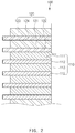
- An electrode assembly 100 according to a first embodiment of the present invention comprises a radical unit 110 and a safety unit 120 disposed on the outermost surface of the radical unit 110 as illustrated in FIGS. 1 and 2 .
- the radical unit 110 is provided with first and second electrodes, which are stacked with a separator therebetween.
- the first electrode is stacked at the outermost side.
- the radical unit 110 comprises first electrodes 111 and the second electrodes 113, which are alternately stacked in a direction from the top to the bottom, and a separator 112 disposed between each of the first electrodes 111 and each of the second electrodes 113.
- the first electrode 111 comprises a first collector and a first electrode active material applied on a surface of the first collector
- the second electrode 113 comprises a second collector and a second electrode active material applied on a surface of the second collector.
- the first electrode may be a negative electrode
- the second electrode may be a positive electrode
- the first collector is made of a copper (CU) material
- a second collector made of an aluminum (Al) material.
- the safety unit 120 is configured to suppress a rise in temperature of the radical unit and comprises a first safety plate 121 disposed above the outermost surface of the radical unit 110 and a first semiconductor material 122 provided between the radical unit 110 and the first safety plate 121.
- the first safety plate 121 is configured to suppress the rise in temperature of the radical unit and is made of a metal or non-metal having thermal conductivity.
- the first safety plate 121 may be made of an aluminum (Al) material. That is, when the temperature of radical unit 110 rises, the first safety plate 121 may absorb heat of the radical unit to dissipate the heat to the outside, thereby capable of suppressing the rise in temperature of the radical unit.
- Al aluminum
- the aluminum is a material having superior electrical conductivity, the heat generated in the radical unit may be effectively absorbed and dissipated.
- the first safety plate 121 may be made of the same material as the collector of the second electrode 113.
- the first semiconductor material 122 is disposed between the radical unit 110 and the first safety plate 121 to electrically connect the radical unit 110 to the first safety plate 121 or electrically disconnect the radical unit 110 from the first safety plate 121 according to the temperature variation.
- the first semiconductor material 122 is maintained as an insulator to disconnect the radical unit 110 from the first safety plate 121 when the temperature of the radical unit 110 is maintained at a first set temperature or less.
- the first semiconductor material 122 may change from the insulator to a conductor to connect the radical unit 110 to the first safety plate 121 so that current flows. Accordingly, the heat generated in the radical unit 110 may be conducted to the first safety plate 121 and then dissipated. As a result, the temperature of the radical unit 110 may be prevented from rising to the first set temperature or more.
- the first semiconductor material 122 may connect or disconnect the radical unit 110 to/from the first safety plate 121 according to the temperature variation of the radical unit 110. As a result, the rise in temperature of the radical unit 110 may be effectively suppressed.
- the first set temperature may be 60°C to 80°C.
- the first set temperature may be 80°C. That is, a change (that is, contraction) occurs in the separator 112 of the radical unit 110 at the temperature of 60°C to 80°C, preferably, 80°C. In this case, the possibility of occurrence of short-circuit increases.
- the first set temperature is set to 60°C to 80°C so as to prevent the above, the temperature of the radical unit 110 may be prevented from rising to 60°C to 80°C or more. Accordingly, the separator 112 may be previously prevented from changing to reduce the possibility of occurrence of the short-circuit.
- the separator 112 has an area larger than that of each of the first and second electrodes 111 and 113, and the first semiconductor material 122 has the same area as the separator 112. That is, since the first semiconductor material 122 has the same area as the separator 112, the radical unit 110 and the first safety plate 121 may be separated from each other so that the current does not flow between the radical unit 110 and the first safety plate 121 at the first set temperature or less.
- the semiconductor material 122 may have the same thickness as the semiconductor material 112 to minimize an increase in thickness of the electrode assembly 100.
- the first safety plate 121 has the same area as each of the first and second electrodes 111 and 113 and has an area less than that of the first semiconductor material 122. Accordingly, even when a skew fail occurs between the radical unit 110 and the first safety plate 121, the radical unit 110 and the first safety plate 121 may be prevented from being connected to each other.
- the first safety plate 121 has a thickness greater than that of each of the first electrode and the second electrode. Accordingly, heat dissipation performance of the first safety plate 121 may increase significantly. As a result, the heat generated in the radical unit 110 may be rapidly absorbed and then dissipated to the outside.
- the first semiconductor material 122 may be made of a phase transition material that changes from an insulator to a conductor, and the phase transition material may be germanium or silicon.
- the germanium and the silicon are semiconductors and have a feature in which electrons move at a predetermined temperature.
- the germanium that is the semiconductor has high resistance because vibratory motion of atoms are significantly reduced at a low temperature. Accordingly, the germanium may serve as an insulator.
- the first semiconductor material 122 has the characteristics as the insulator at a low temperature and has a property of changing into the conductor at a high temperature.
- the safety unit 120 having the above-described constituents may comprise the first safety plate 121 and the first semiconductor material 122 to prevent the temperature of the radical unit 110 from rising to the first set temperature or more. As a result, the electrode assembly 110 may be prevented from being ignited or exploded.
- the safety unit 120 further comprises a second safety plate 123 disposed on an outer surface of the first safety plate 121 and a second semiconductor material 124 provided between the first safety plate 121 and the second safety plate 123. That is, if the first safety plate 121 and the first semiconductor material 122 do not suppress the rise in temperature of the radical unit 110, the safety unit 120 may suppress again the rise in temperature of the radical unit 110 by using the second safety plate 123 and the second semiconductor material 124.
- the second safety plate 123 dissipates the heat generated in the radical unit together with the first safety plate 121 to suppress the rise in temperature of the radical unit 110.
- the second safety plate 123 is made of a metal or non-metal having thermal conductivity, preferably, a copper (Cu) material. That is, the copper (Cu) has conductivity higher than that of the aluminum. Accordingly, the heat generated in the radical unit may be effectively absorbed and then dissipated to the outside. As a result, the rise in temperature of the radical unit 110 may be significantly suppressed.
- a metal or non-metal having thermal conductivity preferably, a copper (Cu) material. That is, the copper (Cu) has conductivity higher than that of the aluminum. Accordingly, the heat generated in the radical unit may be effectively absorbed and then dissipated to the outside. As a result, the rise in temperature of the radical unit 110 may be significantly suppressed.
- the second safety plate 123 may be made of the same material as the first collector of the first electrode 111.
- the second semiconductor material 124 is disposed between the first safety plate 121 and the second safety plate 123 to connect or disconnect the first safety plate 121 to/from the second safety plate 123 according to the temperature variation.
- the second semiconductor material 124 may serve as the insulator to disconnect the first safety plate 121 from the second safety plate 123. Also, when the temperature of the radical unit 110 rises to the second set temperature or more, the second semiconductor material 124 may change from the insulator to the conductor to connect the first safety plate 121 to the second safety plate 123 so that the current flows. Accordingly, the heat of the first safety plate 121 is conducted to the second safety plate 123 and then dissipated. In other words, the heat generated in the radical unit 110 may be conducted to the first safety plate 121 and the second safety plate 123 to suppress the temperature of the radical unit 110 to significantly prevent the electrode assembly from being ignited and exploded.
- the second set temperature is higher than the first set temperature.
- the second set temperature may be 80°C to 100°C.
- the second set temperature may be 100°C. That is, the possibility of ignition in the radical unit 110 due to the change of the separator 112 may increases at the temperature of 80°C to 100°C, preferably, 100°C. Accordingly, when the second set temperature is set to 80°C to 100°C, the temperature of the radical unit may be prevented from rising to 80°C to 100°C or more. As a result, the ignition of the electrode assembly may be prevented.
- the second semiconductor material 124 may be made of a material having a phase transition temperature higher than that of the first semiconductor material 122. This is done for preventing the phase transition of the second semiconductor material 124, even when the phase transition of the first semiconductor material 122 occurs. That is, each of the second semiconductor material 124 and the first semiconductor material 122 is made of germanium or silicon. Here, the second semiconductor material 124 further contains compounds and thus has a phase transition temperature higher than that of the first semiconductor material 122.
- the second semiconductor material 124 has the same size as the first semiconductor material 122.
- the second safety plate 123 has a size greater than that of the first safety plate 121 and less than or equal to that of the second semiconductor material 124.
- the electrode assembly may be prevented from increasing in volume and also prevent the first safety plate 121 and the second safety plate 123 from being connected to each other at the second set temperature or less.
- the second safety plate 123 has a thickness greater than that of the first safety plate 121. Accordingly, the second safety plate 123 has heat dissipation performance higher than that of the first safety plate 121 to more stably reduce the temperature of the radical unit 110.
- the electrode assembly 100 may comprise the safety unit 120 to suppress the rise in temperature of the radical unit, thereby preventing the radical unit from being ignited and exploded.
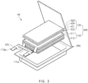
- a secondary battery 10 according to a second embodiment of the present invention comprises an electrode assembly 100 and a case that accommodates the electrode assembly 100 as illustrated in FIG. 3 .
- the electrode assembly 100 comprises a radical unit 110 which comprises first and second electrodes 111 and 113 stacked with a separator 112 therebetween, wherein the first electrode 111 is stacked at the outermost side, and a safety unit 120 disposed on the outermost surface of the radical unit 110.
- the safety unit 120 comprises a first safety plate 121 disposed above the outermost surface of the radical unit 110 and a first semiconductor material 122 provided between the radical unit 110 and the first safety plate 121.
- the first semiconductor material 122 may serve as an insulator at a first set temperature or less to disconnect the radical unit 110 from the first safety plate 121 and may change from the insulator to a conductor at the first set temperature or more to connect the radical unit 110 to the first safety plate 121 so that the radical unit 110 and the first safety plate 121 are electrically conducted with respect to each other.
- heat of the radical unit 110 is conducted to the first safety plate 121 and then dissipated.
- the safety unit 120 further comprises a second safety plate 123 disposed on an outer surface of the first safety plate 121 and a second semiconductor material 124 provided between the first safety plate 121 and the second safety plate 123. That is, in the safety unit 120, when the temperature of the radical unit 110 is below a second set temperature, the second semiconductor material 124 may serve as the insulator to disconnect the first safety plate 121 from the second safety plate 123, and when the temperature of the radical unit 110 is above the second set temperature, the second semiconductor material 124 may change from the insulator to the conductor to connect the first safety pate 121 to the second safety plate 123 so that the first safety plate 121 and the second safety plate 123 are conducted with respect to each other. Thus, the heat of the first safety plate 121 is conducted to the second safety plate 123 to prevent a rise in temperature of the electrode assembly.
- the case 200 comprises an accommodation part that accommodates the electrode assembly 100 and a sealing part that seals the accommodation part.
- the electrode assembly 100 comprises a first electrode lead 111a connected to the first electrode 111 and having an end that is drawn to the outside of the case 200 and a second electrode lead 113a connected to the second electrode 113 and having an end that is drawn to the outside of the case 200.
- the electrode assembly comprises a third semiconductor material 125 between the first electrode lead 111a and the second electrode lead 113a.
- the third semiconductor material 125 may serve as an insulator to disconnect the first electrode lead 111a from the second electrode lead 113a when the temperature of the radical unit is maintained at a third set temperature or less and may change from the insulator to a conductor to connect the first electrode lead 111a to the second electrode lead 113a so that the first electrode lead 111a and the second electrode lead 113a are conducted with respect to each other when the temperature of the radical unit rises to the third set temperature or more, thereby generating short-circuit.
- the third semiconductor material 125 may connect or disconnect the first electrode lead 111a to/from the second electrode lead 113a according to the temperature variation of the radical unit 110. Accordingly, the temperature of the radical unit 110 may be prevented from rising to the third set temperature or more. As a result, the ignition or explosion due to thermal runaway of the radical unit 110 may be prevented.
- the third semiconductor material 125 may be made of a phase transition material.
- the third set temperature is higher than the second set temperature.
- the third set temperature may be 100°C to 110°C, preferably, 110°C. That is, the thermal runaway (degradation or breakage due to heat) occurs at a temperature of 100°C to 110°C, preferably, 110°C.
- the third set temperature may be set to 100°C to 110°C to prevent the thermal runaway of the radical unit from occurring.
- the secondary battery 10 may comprise the electrode assembly 100 provided with the safety unit 120 to prevent the temperature of the electrode assembly 100 from rising to the set temperature or more, thereby preventing the ignition and explosion.
- the temperature of the radical unit 110 rises rapidly.
- the rise in temperature of the radical unit 110 may be suppressed by the safety unit 120.
- the first semiconductor material 122 may serve as the insulator to disconnect the radical unit 110 from the first safety plate 121, and when the temperature of the radical unit 110 rises to the first set temperature or more, the first semiconductor material 122 may change from the insulator to the conductor to connect the radical unit 110 to the first safety plate 121 so that the radical unit 110 and the first safety plate 121 are conducted with respect to each other. Therefore, the heat generated in the radical unit 110 may be conducted to the first safety plate 121 and then dissipated to the outside to suppress the temperature of the radical unit 110 to the first set temperature or more.
- the safety unit 120 suppresses again the rise in temperature of the radical unit 110 by using the second safety plate 123 and the second semiconductor material 124.
- the second semiconductor material 124 changes from the insulator to the conductor to connect the first safety plate 121 to the second safety plate 123 so that the first safety plate 121 to the second safety plate 123 are conducted with respect to each other, thereby dissipating the heat of the first safety plate 121 conducted to the second safety plate 123. That is, as the heat generated in the radical unit 110 is absorbed into the first safety plate 121 and the second safety plate 123 and then dissipated to the outside, the temperature is suppressed to the second set temperature or less to significantly prevent the radical unit 110 from being ignited and exploded.
- the safety unit 120 suppresses the rise in temperature of the radical unit 110 by using the third semiconductor material 125.
- the third semiconductor material 125 may change from the insulator to the conductor to connect the first electrode lead 111a to the second electrode lead 113a, which are provided in the radical unit 110, thereby generating the short-circuit from occurring in advance. Therefore, the voltage and temperature of the radical unit 110 may be reduced to suppress the rise in temperature of the radical unit 110, thereby preventing the ignition and explosion from occurring.
- a battery pack comprising the secondary battery according to the second embodiment may be archived.
- a battery pack according to a third embodiment of the present invention comprises a secondary battery and a pack case that accommodates the secondary battery.
- the secondary battery comprises an electrode assembly and a case that accommodates the electrode assembly.
- the electrode assembly comprises a radical unit which comprises first and second electrodes stacked with a separator therebetween, wherein the first electrode 111 is stacked at the outermost side, and a safety unit which is disposed on the outermost surface of the radical unit.
- the safety unit comprises a first safety plate disposed above the outermost surface of the radical unit and a first semiconductor material provided between the radical unit and the first safety plate.
- the first semiconductor material may serve as an insulator at a first set temperature or less to disconnect the radical unit from the first safety plate and may change from the insulator to a conductor at the first set temperature or more to connect the radical unit to the first safety plate, thereby dissipating the heat of the radical unit while conducting the heat to the first safety plate.
- the secondary battery has the same constituent as the secondary battery described above in the second embodiment, and thus its duplicated descriptions will be omitted.
- the battery pack according to the third embodiment may significantly improve the safety.
- Germanium is prepared as a first semiconductor material according to the present invention, and then resistance values of the germanium are measured according to a temperature variation. As a result, a graph illustrated in FIG. 5 may be obtained.
- the germanium has resistance of about 3500 ⁇ to 2000 ⁇ at a temperature of 60°C to 80°C. That is, the germanium has high resistance at the temperature of 60°C to 80°C and thus exhibits characteristics as an insulator through which current does not flow. Also, the germanium has resistance of about 2000 ⁇ or less at a temperature of 80°C or more. That is, the germanium has characteristics as a conductor through which current begins to flow at resistance of 2000 ⁇ or less. In other words, the germanium changes in property from the insulator to the conductor.
- the first semiconductor material according to the present invention may be made of the germanium of which the resistance value changes according to the temperature variation to reduce the temperature of the radical unit according to the temperature variation of the radical unit.
Landscapes
- Chemical & Material Sciences (AREA)
- Chemical Kinetics & Catalysis (AREA)
- Electrochemistry (AREA)
- General Chemical & Material Sciences (AREA)
- Engineering & Computer Science (AREA)
- Manufacturing & Machinery (AREA)
- Automation & Control Theory (AREA)
- Life Sciences & Earth Sciences (AREA)
- Biophysics (AREA)
- Connection Of Batteries Or Terminals (AREA)
- Secondary Cells (AREA)
- Battery Mounting, Suspending (AREA)
Abstract
Description
- The present application claims the benefit of the priority of Korean Patent Application No.
10-2018-0118864, filed on October 05, 2018 - The present invention relates to an electrode assembly, a secondary battery comprising the same, and a battery pack, and more particularly, to an electrode assembly having improved safety, a secondary battery comprising the same, and a battery pack.
- In generally, secondary batteries are chargeable and dischargeable batteries unlike primary batteries that are not chargeable. Such secondary batteries are being used in hightech electronic devices such as cellular phones, laptop computers, camcorders, and the like.
- These secondary batteries are classified into a cantype secondary battery in which an electrode assembly is embedded in a metal can and a pouch-type secondary battery in which an electrode assembly is embedded in a pouch. The pouch-type secondary battery comprises an electrode assembly in which electrodes and separators are alternately stacked, an electrolyte, and a pouch that accommodates the electrode assembly and the electrolyte. Also, the pouch comprises an accommodation part that accommodates the electrode assembly and the electrolyte and a sealing part that seals the accommodation part.
- However, there has been a problem in which the temperature of the secondary batteries rises rapidly to cause ignition or explosion when short-circuit occurs due to overcharging or external impact.
- The present invention has been made to solve the above-described problem, and an objective of the present invention is to provide an electrode assembly of which a temperature is prevented from rising to a set temperature or more to prevent ignition or explosion from occurring, a secondary battery comprising the same, and a battery pack.
- An electrode assembly according to the present invention in order to achieve the objective may comprise: a radical unit provided with first and second electrodes stacked with a separator therebetween, wherein the first electrode is stacked at the outermost side; and a safety unit disposed on the outermost surface of the radical unit, wherein the safety unit comprises: a first safety plate disposed above the outermost surface of the radical unit; and a first semiconductor material provided between the radical unit and the first safety plate, wherein the first semiconductor material serves as an insulator at a first set temperature or less to disconnect the radical unit to the first safety plate and changes from the insulator to a conductor at the first set temperature or more to connect the radical unit to the first safety plate, thereby dissipating heat of the radical unit while conducting the heat to the first safety plate.
- The first set temperature may be 60°C to 80°C.
- The separator may have an area greater than that of the electrodes, the first semiconductor material may have the same area as the semiconductor, and the first safety plate may have the same area as the first or second electrode.
- The safety unit may further comprise: a second safety plate disposed outside the first safety plate; and a second semiconductor material provided between the first safety plate and the second safety plate, wherein the second semiconductor material serves as an insulator at a second set temperature or less to disconnect the first safety plate from the second safety plate and changes from the insulator to a conductor at the second set temperature or more to connect the first safety plate to the second safety plate, thereby dissipating heat of the first safety plate while conducting the heat to the second safety plate.
- The second set temperature may be 80°C to 100°C.
- The first safety plate may be made of an aluminum (Al) material, and the second safety plate is made of a copper (Cu) material.
- The second semiconductor material may have the same size as the first semiconductor material, and the second safety plate may have a size greater than that of the first safety plate and less than or equal to that of the second semiconductor material.
- The second safety plate may have a thickness greater than that of the first safety plate.
- Each of the first semiconductor material and the second semiconductor material may be made of germanium or silicon.
- Also, a secondary battery according to the present invention may comprise: an electrode assembly; and a case configured to accommodate the electrode assembly, wherein the electrode assembly comprises: a radical unit provided with first and second electrodes stacked with a separator therebetween, wherein the first electrode is stacked at the outermost side; and a safety unit disposed on the outermost surface of the radical unit, wherein the safety unit comprises: a first safety plate disposed above the outermost surface of the radical unit; and a first semiconductor material provided between the radical unit and the first safety plate, wherein the first semiconductor material serves as an insulator at a first set temperature or less to disconnect the radical unit to the first safety plate and changes from the insulator to a conductor at the first set temperature or more to connect the radical unit to the first safety plate, thereby dissipating heat of the radical unit while conducting the heat to the first safety plate.
- The safety unit may further comprise: a second safety plate disposed outside the first safety plate; and a second semiconductor material provided between the first safety plate and the second safety plate, wherein the second semiconductor material serves as an insulator at a second set temperature or less to disconnect the first safety plate from the second safety plate and changes from the insulator to a conductor at the second set temperature or more to connect the first safety plate to the second safety plate, thereby dissipating heat of the first safety plate while conducting the heat to the second safety plate.
- The electrode assembly may comprise: a first electrode lead connected to the first electrode and having an end drawn to the outside of the case; and a second electrode lead connected to the second electrode and having an end drawn to the outside of the case, and the electrode assembly may further comprise a third semiconductor material between the first electrode lead and the second electrode lead, wherein the third semiconductor material serves as an insulator at a third set temperature or less to disconnect the first electrode lead from the second electrode lead and changes from the insulator to a conductor at the third set temperature or more to connect the first electrode lead to the second electrode lead, thereby generating short-circuit.
- The third set temperature may be 100°C to 110°C.
- Also, a battery pack according to the present invention may comprise a secondary battery provided with an electrode assembly and a case configured to accommodate the electrode assembly, wherein the electrode assembly comprises: a radical unit provided with first and second electrodes stacked with a separator therebetween, wherein the first electrode is stacked at the outermost side; and a safety unit disposed on the outermost surface of the radical unit, wherein the safety unit comprises: a first safety plate disposed above the outermost surface of the radical unit; and a first semiconductor material provided between the radical unit and the first safety plate, wherein the first semiconductor material serves as an insulator at a first set temperature or less to disconnect the radical unit to the first safety plate and changes from the insulator to a conductor at the first set temperature or more to connect the radical unit to the first safety plate, thereby dissipating heat of the radical unit while conducting the heat to the first safety plate.
- The electrode assembly according to the present invention may comprise the radical unit and the safety unit provided with the first safety plate and the first semiconductor material. Therefore, when the temperature of the electrode assembly rises to the first set temperature or more, the rise in temperature of the electrode assembly may be suppressed by the safety unit to prevent the electrode assembly from being ignited and exploded.
- That is, when the temperature of the electrode assembly is maintained at the first set temperature or less, the safety unit may disconnect the radical unit from the first safety plate through the first semiconductor material, which is the insulator. On the other hand, when the temperature of the electrode assembly rises to the first set temperature or more, the first semiconductor material, which is the insulator, may change into to the conductor to connect the radical unit to the first safety plate. Accordingly, the heat generated in the radical unit may be conducted to the first safety plate and then dissipated. As a result, the temperature of the electrode assembly may be prevented from rising to the first set temperature or more, thereby preventing the ignition and explosion from occurring.
- Also, the safety unit according to the present invention may comprise the second safety plate and the second semiconductor material. Here, the second semiconductor material may change into the conductor at the temperature greater than that of the first semiconductor material. Therefore, when the temperature of the electrode assembly rises to the second set temperature or more, the second semiconductor material, which is the insulator, may change into the conductor to connect the first safety plate to the second safety plate. Accordingly, the heat of the radical unit may be conducted to the first and second safety plates and then dissipated. As a result, the temperature of the electrode assembly may be prevented from rising to the second set temperature or more.
- Also, the safety unit according to the present invention may comprise the third semiconductor material. Here, the third semiconductor material may change into the conductor at the temperature greater than that of the second semiconductor material. Therefore, when the temperature of the electrode assembly rises to the third set temperature or more, the third semiconductor material, which is the insulator, may change into the conductor to connect the first electrode lead to the second electrode lead, thereby generating the short-circuit. Accordingly, the temperature of the electrode assembly may be prevented from rising to the third set temperature or more, thereby preventing the ignition and explosion from occurring.
-
-
FIG. 1 is a cross-sectional view of an electrode assembly according to a first embodiment of the present invention. -
FIG. 2 is a partially enlarged view ofFIG. 1 . -
FIG. 3 is a perspective view of a secondary battery according to a second embodiment of the present invention. -
FIG. 4 is a plan view illustrating the secondary battery according to the second embodiment of the present invention. -
FIG. 5 is a graph showing an experimental example according to the present invention. - Hereinafter, preferred embodiments of the present invention will be described in detail with reference to the accompanying drawings so as to be easily carried out by a person skilled in the art to which the present invention pertains. The present invention may, however, be embodied in different forms and should not be construed as limited to the embodiments set forth herein. In the drawings, anything unnecessary for describing the present invention will be omitted for clarity, and also like reference numerals refer to like elements throughout.
- An
electrode assembly 100 according to a first embodiment of the present invention comprises aradical unit 110 and asafety unit 120 disposed on the outermost surface of theradical unit 110 as illustrated inFIGS. 1 and2 . - The
radical unit 110 is provided with first and second electrodes, which are stacked with a separator therebetween. Here, the first electrode is stacked at the outermost side. - For example, referring to
FIG. 1 , theradical unit 110 comprisesfirst electrodes 111 and thesecond electrodes 113, which are alternately stacked in a direction from the top to the bottom, and aseparator 112 disposed between each of thefirst electrodes 111 and each of thesecond electrodes 113. - The
first electrode 111 comprises a first collector and a first electrode active material applied on a surface of the first collector, and Thesecond electrode 113 comprises a second collector and a second electrode active material applied on a surface of the second collector. - Here, the first electrode may be a negative electrode, and the second electrode may be a positive electrode. Also, the first collector is made of a copper (CU) material, and a second collector made of an aluminum (Al) material.
- The
safety unit 120 is configured to suppress a rise in temperature of the radical unit and comprises afirst safety plate 121 disposed above the outermost surface of theradical unit 110 and afirst semiconductor material 122 provided between theradical unit 110 and thefirst safety plate 121. - The
first safety plate 121 is configured to suppress the rise in temperature of the radical unit and is made of a metal or non-metal having thermal conductivity. Preferably, thefirst safety plate 121 may be made of an aluminum (Al) material. That is, when the temperature ofradical unit 110 rises, thefirst safety plate 121 may absorb heat of the radical unit to dissipate the heat to the outside, thereby capable of suppressing the rise in temperature of the radical unit. In particular, since the aluminum is a material having superior electrical conductivity, the heat generated in the radical unit may be effectively absorbed and dissipated. - Also, the
first safety plate 121 may be made of the same material as the collector of thesecond electrode 113. - The
first semiconductor material 122 is disposed between theradical unit 110 and thefirst safety plate 121 to electrically connect theradical unit 110 to thefirst safety plate 121 or electrically disconnect theradical unit 110 from thefirst safety plate 121 according to the temperature variation. - That is, the
first semiconductor material 122 is maintained as an insulator to disconnect theradical unit 110 from thefirst safety plate 121 when the temperature of theradical unit 110 is maintained at a first set temperature or less. Here, even when the heat is generated in theradical unit 110, the heat is not conducted to thefirst safety plate 121. Also, when the temperature of theradical unit 110 rises to the first set temperature or more, thefirst semiconductor material 122 may change from the insulator to a conductor to connect theradical unit 110 to thefirst safety plate 121 so that current flows. Accordingly, the heat generated in theradical unit 110 may be conducted to thefirst safety plate 121 and then dissipated. As a result, the temperature of theradical unit 110 may be prevented from rising to the first set temperature or more. - In other words, the
first semiconductor material 122 may connect or disconnect theradical unit 110 to/from thefirst safety plate 121 according to the temperature variation of theradical unit 110. As a result, the rise in temperature of theradical unit 110 may be effectively suppressed. - Here, the first set temperature may be 60°C to 80°C. Preferably, the first set temperature may be 80°C. That is, a change (that is, contraction) occurs in the
separator 112 of theradical unit 110 at the temperature of 60°C to 80°C, preferably, 80°C. In this case, the possibility of occurrence of short-circuit increases. When the first set temperature is set to 60°C to 80°C so as to prevent the above, the temperature of theradical unit 110 may be prevented from rising to 60°C to 80°C or more. Accordingly, theseparator 112 may be previously prevented from changing to reduce the possibility of occurrence of the short-circuit. - Also, the
separator 112 has an area larger than that of each of the first andsecond electrodes first semiconductor material 122 has the same area as theseparator 112. That is, since thefirst semiconductor material 122 has the same area as theseparator 112, theradical unit 110 and thefirst safety plate 121 may be separated from each other so that the current does not flow between theradical unit 110 and thefirst safety plate 121 at the first set temperature or less. - Also, the
semiconductor material 122 may have the same thickness as thesemiconductor material 112 to minimize an increase in thickness of theelectrode assembly 100. - Also, the
first safety plate 121 has the same area as each of the first andsecond electrodes first semiconductor material 122. Accordingly, even when a skew fail occurs between theradical unit 110 and thefirst safety plate 121, theradical unit 110 and thefirst safety plate 121 may be prevented from being connected to each other. - Also, the
first safety plate 121 has a thickness greater than that of each of the first electrode and the second electrode. Accordingly, heat dissipation performance of thefirst safety plate 121 may increase significantly. As a result, the heat generated in theradical unit 110 may be rapidly absorbed and then dissipated to the outside. - Also, the
first semiconductor material 122 may be made of a phase transition material that changes from an insulator to a conductor, and the phase transition material may be germanium or silicon. The germanium and the silicon are semiconductors and have a feature in which electrons move at a predetermined temperature. Here, referring toFIG. 5 , the germanium that is the semiconductor has high resistance because vibratory motion of atoms are significantly reduced at a low temperature. Accordingly, the germanium may serve as an insulator. Also, when the temperature rises, the resistance is reduced while the vibratory motion of the atoms increases. Accordingly, the insulator is changed into the conductor to allow the current to flow well therethrough. In summary, thefirst semiconductor material 122 has the characteristics as the insulator at a low temperature and has a property of changing into the conductor at a high temperature. - The
safety unit 120 having the above-described constituents may comprise thefirst safety plate 121 and thefirst semiconductor material 122 to prevent the temperature of theradical unit 110 from rising to the first set temperature or more. As a result, theelectrode assembly 110 may be prevented from being ignited or exploded. - Also, the
safety unit 120 further comprises asecond safety plate 123 disposed on an outer surface of thefirst safety plate 121 and asecond semiconductor material 124 provided between thefirst safety plate 121 and thesecond safety plate 123. That is, if thefirst safety plate 121 and thefirst semiconductor material 122 do not suppress the rise in temperature of theradical unit 110, thesafety unit 120 may suppress again the rise in temperature of theradical unit 110 by using thesecond safety plate 123 and thesecond semiconductor material 124. - In more detail, when the heat of the
first safety plate 121 is conducted to thesecond safety plate 123, thesecond safety plate 123 dissipates the heat generated in the radical unit together with thefirst safety plate 121 to suppress the rise in temperature of theradical unit 110. - Here, the
second safety plate 123 is made of a metal or non-metal having thermal conductivity, preferably, a copper (Cu) material. That is, the copper (Cu) has conductivity higher than that of the aluminum. Accordingly, the heat generated in the radical unit may be effectively absorbed and then dissipated to the outside. As a result, the rise in temperature of theradical unit 110 may be significantly suppressed. - Particularly, the
second safety plate 123 may be made of the same material as the first collector of thefirst electrode 111. - The
second semiconductor material 124 is disposed between thefirst safety plate 121 and thesecond safety plate 123 to connect or disconnect thefirst safety plate 121 to/from thesecond safety plate 123 according to the temperature variation. - That is, when the temperature of the
radical unit 110 is maintained at the second set temperature or less, thesecond semiconductor material 124 may serve as the insulator to disconnect thefirst safety plate 121 from thesecond safety plate 123. Also, when the temperature of theradical unit 110 rises to the second set temperature or more, thesecond semiconductor material 124 may change from the insulator to the conductor to connect thefirst safety plate 121 to thesecond safety plate 123 so that the current flows. Accordingly, the heat of thefirst safety plate 121 is conducted to thesecond safety plate 123 and then dissipated. In other words, the heat generated in theradical unit 110 may be conducted to thefirst safety plate 121 and thesecond safety plate 123 to suppress the temperature of theradical unit 110 to significantly prevent the electrode assembly from being ignited and exploded. - Also, the second set temperature is higher than the first set temperature. For example, the second set temperature may be 80°C to 100°C. Preferably, the second set temperature may be 100°C. That is, the possibility of ignition in the
radical unit 110 due to the change of theseparator 112 may increases at the temperature of 80°C to 100°C, preferably, 100°C. Accordingly, when the second set temperature is set to 80°C to 100°C, the temperature of the radical unit may be prevented from rising to 80°C to 100°C or more. As a result, the ignition of the electrode assembly may be prevented. - Also, the
second semiconductor material 124 may be made of a material having a phase transition temperature higher than that of thefirst semiconductor material 122. This is done for preventing the phase transition of thesecond semiconductor material 124, even when the phase transition of thefirst semiconductor material 122 occurs. That is, each of thesecond semiconductor material 124 and thefirst semiconductor material 122 is made of germanium or silicon. Here, thesecond semiconductor material 124 further contains compounds and thus has a phase transition temperature higher than that of thefirst semiconductor material 122. - Also, the
second semiconductor material 124 has the same size as thefirst semiconductor material 122. Here, thesecond safety plate 123 has a size greater than that of thefirst safety plate 121 and less than or equal to that of thesecond semiconductor material 124. Thus, the electrode assembly may be prevented from increasing in volume and also prevent thefirst safety plate 121 and thesecond safety plate 123 from being connected to each other at the second set temperature or less. - Also, the
second safety plate 123 has a thickness greater than that of thefirst safety plate 121. Accordingly, thesecond safety plate 123 has heat dissipation performance higher than that of thefirst safety plate 121 to more stably reduce the temperature of theradical unit 110. - Therefore, the
electrode assembly 100 according to the first embodiment of the present invention may comprise thesafety unit 120 to suppress the rise in temperature of the radical unit, thereby preventing the radical unit from being ignited and exploded. - Hereinafter, in describing another embodiment according to the present invention, constituents having the same configuration and function have been given with the same reference numerals, and thus their duplicated descriptions will be omitted.
- A
secondary battery 10 according to a second embodiment of the present invention comprises anelectrode assembly 100 and a case that accommodates theelectrode assembly 100 as illustrated inFIG. 3 . - The
electrode assembly 100 comprises aradical unit 110 which comprises first andsecond electrodes separator 112 therebetween, wherein thefirst electrode 111 is stacked at the outermost side, and asafety unit 120 disposed on the outermost surface of theradical unit 110. - The
safety unit 120 comprises afirst safety plate 121 disposed above the outermost surface of theradical unit 110 and afirst semiconductor material 122 provided between theradical unit 110 and thefirst safety plate 121. - Here, the
first semiconductor material 122 may serve as an insulator at a first set temperature or less to disconnect theradical unit 110 from thefirst safety plate 121 and may change from the insulator to a conductor at the first set temperature or more to connect theradical unit 110 to thefirst safety plate 121 so that theradical unit 110 and thefirst safety plate 121 are electrically conducted with respect to each other. Thus, heat of theradical unit 110 is conducted to thefirst safety plate 121 and then dissipated. - Also, the
safety unit 120 further comprises asecond safety plate 123 disposed on an outer surface of thefirst safety plate 121 and asecond semiconductor material 124 provided between thefirst safety plate 121 and thesecond safety plate 123. That is, in thesafety unit 120, when the temperature of theradical unit 110 is below a second set temperature, thesecond semiconductor material 124 may serve as the insulator to disconnect thefirst safety plate 121 from thesecond safety plate 123, and when the temperature of theradical unit 110 is above the second set temperature, thesecond semiconductor material 124 may change from the insulator to the conductor to connect thefirst safety pate 121 to thesecond safety plate 123 so that thefirst safety plate 121 and thesecond safety plate 123 are conducted with respect to each other. Thus, the heat of thefirst safety plate 121 is conducted to thesecond safety plate 123 to prevent a rise in temperature of the electrode assembly. - The
case 200 comprises an accommodation part that accommodates theelectrode assembly 100 and a sealing part that seals the accommodation part. - Also, the
electrode assembly 100 comprises afirst electrode lead 111a connected to thefirst electrode 111 and having an end that is drawn to the outside of thecase 200 and asecond electrode lead 113a connected to thesecond electrode 113 and having an end that is drawn to the outside of thecase 200. - Here, the electrode assembly comprises a
third semiconductor material 125 between thefirst electrode lead 111a and thesecond electrode lead 113a. Thethird semiconductor material 125 may serve as an insulator to disconnect thefirst electrode lead 111a from thesecond electrode lead 113a when the temperature of the radical unit is maintained at a third set temperature or less and may change from the insulator to a conductor to connect thefirst electrode lead 111a to thesecond electrode lead 113a so that thefirst electrode lead 111a and thesecond electrode lead 113a are conducted with respect to each other when the temperature of the radical unit rises to the third set temperature or more, thereby generating short-circuit. - That is, the
third semiconductor material 125 may connect or disconnect thefirst electrode lead 111a to/from thesecond electrode lead 113a according to the temperature variation of theradical unit 110. Accordingly, the temperature of theradical unit 110 may be prevented from rising to the third set temperature or more. As a result, the ignition or explosion due to thermal runaway of theradical unit 110 may be prevented. - Also, the
third semiconductor material 125 may be made of a phase transition material. - Here, the third set temperature is higher than the second set temperature. For example, the third set temperature may be 100°C to 110°C, preferably, 110°C. That is, the thermal runaway (degradation or breakage due to heat) occurs at a temperature of 100°C to 110°C, preferably, 110°C. Thus, the third set temperature may be set to 100°C to 110°C to prevent the thermal runaway of the radical unit from occurring.
- Therefore, the
secondary battery 10 according to the second embodiment of the present invention may comprise theelectrode assembly 100 provided with thesafety unit 120 to prevent the temperature of theelectrode assembly 100 from rising to the set temperature or more, thereby preventing the ignition and explosion. - Hereinafter, a use state of the
secondary battery 10 according to the second embodiment of the present invention will be described. - First, when the
secondary battery 10 is charged, a temperature rises as theradical unit 110 of theelectrode assembly 100 accommodated in thecase 200 is charged. Here, if theradical unit 110 of theelectrode assembly 100 is overcharged, the temperature of theradical unit 110 rises rapidly. In this case, when the temperature of theradical unit 110 rises to the first set temperature of 60°C to 80°C or more, the rise in temperature of theradical unit 110 may be suppressed by thesafety unit 120. - That is, in the
safety unit 120, when the temperature of theradical unit 110 is maintained at the first set temperature or less, thefirst semiconductor material 122 may serve as the insulator to disconnect theradical unit 110 from thefirst safety plate 121, and when the temperature of theradical unit 110 rises to the first set temperature or more, thefirst semiconductor material 122 may change from the insulator to the conductor to connect theradical unit 110 to thefirst safety plate 121 so that theradical unit 110 and thefirst safety plate 121 are conducted with respect to each other. Therefore, the heat generated in theradical unit 110 may be conducted to thefirst safety plate 121 and then dissipated to the outside to suppress the temperature of theradical unit 110 to the first set temperature or more. - Also, when the temperature of the
radical unit 110 rises to the second set temperature of 80°C to 100°C or more, thesafety unit 120 suppresses again the rise in temperature of theradical unit 110 by using thesecond safety plate 123 and thesecond semiconductor material 124. - That is, when the temperature of the
radical unit 110 rises to the second set temperature or more, thesecond semiconductor material 124 changes from the insulator to the conductor to connect thefirst safety plate 121 to thesecond safety plate 123 so that thefirst safety plate 121 to thesecond safety plate 123 are conducted with respect to each other, thereby dissipating the heat of thefirst safety plate 121 conducted to thesecond safety plate 123. That is, as the heat generated in theradical unit 110 is absorbed into thefirst safety plate 121 and thesecond safety plate 123 and then dissipated to the outside, the temperature is suppressed to the second set temperature or less to significantly prevent theradical unit 110 from being ignited and exploded. - Also, when the thermal runaway occurs due to the continuous rise in temperature of the
radical unit 110, thesafety unit 120 suppresses the rise in temperature of theradical unit 110 by using thethird semiconductor material 125. - That is, when the temperature of the
radical unit 110 rises up to the third set temperature of 100°C to 110°C, thethird semiconductor material 125 may change from the insulator to the conductor to connect thefirst electrode lead 111a to thesecond electrode lead 113a, which are provided in theradical unit 110, thereby generating the short-circuit from occurring in advance. Therefore, the voltage and temperature of theradical unit 110 may be reduced to suppress the rise in temperature of theradical unit 110, thereby preventing the ignition and explosion from occurring. - Also, a battery pack comprising the secondary battery according to the second embodiment may be archived.
- That is, a battery pack according to a third embodiment of the present invention comprises a secondary battery and a pack case that accommodates the secondary battery. Here, the secondary battery comprises an electrode assembly and a case that accommodates the electrode assembly.
- The electrode assembly comprises a radical unit which comprises first and second electrodes stacked with a separator therebetween, wherein the
first electrode 111 is stacked at the outermost side, and a safety unit which is disposed on the outermost surface of the radical unit. - The safety unit comprises a first safety plate disposed above the outermost surface of the radical unit and a first semiconductor material provided between the radical unit and the first safety plate.
- The first semiconductor material may serve as an insulator at a first set temperature or less to disconnect the radical unit from the first safety plate and may change from the insulator to a conductor at the first set temperature or more to connect the radical unit to the first safety plate, thereby dissipating the heat of the radical unit while conducting the heat to the first safety plate.
- Here, the secondary battery has the same constituent as the secondary battery described above in the second embodiment, and thus its duplicated descriptions will be omitted.
- Thus, the battery pack according to the third embodiment may significantly improve the safety.
- Germanium is prepared as a first semiconductor material according to the present invention, and then resistance values of the germanium are measured according to a temperature variation. As a result, a graph illustrated in
FIG. 5 may be obtained. - Referring to the graph of
FIG. 5 , the germanium has resistance of about 3500 Ω to 2000 Ω at a temperature of 60°C to 80°C. That is, the germanium has high resistance at the temperature of 60°C to 80°C and thus exhibits characteristics as an insulator through which current does not flow. Also, the germanium has resistance of about 2000 Ω or less at a temperature of 80°C or more. That is, the germanium has characteristics as a conductor through which current begins to flow at resistance of 2000Ω or less. In other words, the germanium changes in property from the insulator to the conductor. - Thus, the first semiconductor material according to the present invention may be made of the germanium of which the resistance value changes according to the temperature variation to reduce the temperature of the radical unit according to the temperature variation of the radical unit.
- The scope of the present invention is defined by the appended claims rather than the detailed descriptions, and it is possible to make various embodiments derived from the meaning and scope of the claims and their equivalents concept.
Claims (14)
- An electrode assembly comprising:a radical unit provided with first and second electrodes stacked with a separator therebetween, wherein the first electrode is stacked at the outermost side; anda safety unit disposed on the outermost surface of the radical unit,wherein the safety unit comprises: a first safety plate disposed above the outermost surface of the radical unit; and a first semiconductor material provided between the radical unit and the first safety plate,wherein the first semiconductor material serves as an insulator at a first set temperature or less to disconnect the radical unit to the first safety plate and changes from the insulator to a conductor at the first set temperature or more to connect the radical unit to the first safety plate, thereby dissipating heat of the radical unit while conducting the heat to the first safety plate.
- The electrode assembly of claim 1, wherein the first set temperature is 60°C to 80°C.
- The electrode assembly of claim 1, wherein the separator has an area greater than that of the electrodes,
the first semiconductor material has the same area as the semiconductor, and
the first safety plate has the same area as the first or second electrode. - The electrode assembly of claim 1, wherein the safety unit further comprises: a second safety plate disposed outside the first safety plate; and a second semiconductor material provided between the first safety plate and the second safety plate,
wherein the second semiconductor material serves as an insulator at a second set temperature or less to disconnect the first safety plate from the second safety plate and changes from the insulator to a conductor at the second set temperature or more to connect the first safety plate to the second safety plate, thereby dissipating heat of the first safety plate while conducting the heat to the second safety plate. - The electrode assembly of claim 4, wherein the second set temperature is 80°C to 100°C.
- The electrode assembly of claim 4, wherein the first safety plate is made of an aluminum (Al) material, and the second safety plate is made of a copper (Cu) material.
- The electrode assembly of claim 4, wherein the second semiconductor material has the same size as the first semiconductor material, and
the second safety plate has a size greater than that of the first safety plate and less than or equal to that of the second semiconductor material. - The electrode assembly of claim 7, wherein the second safety plate has a thickness greater than that of the first safety plate.
- The electrode assembly of claim 1, wherein each of the first semiconductor material and the second semiconductor material is made of germanium or silicon.
- A secondary battery comprising:an electrode assembly; anda case configured to accommodate the electrode assembly,wherein the electrode assembly comprises: a radical unit provided with first and second electrodes stacked with a separator therebetween, wherein the first electrode is stacked at the outermost side; and a safety unit disposed on the outermost surface of the radical unit,wherein the safety unit comprises: a first safety plate disposed above the outermost surface of the radical unit; and a first semiconductor material provided between the radical unit and the first safety plate,wherein the first semiconductor material serves as an insulator at a first set temperature or less to disconnect the radical unit to the first safety plate and changes from the insulator to a conductor at the first set temperature or more to connect the radical unit to the first safety plate, thereby dissipating heat of the radical unit while conducting the heat to the first safety plate.
- The secondary battery of claim 10, wherein the safety unit further comprises: a second safety plate disposed outside the first safety plate; and a second semiconductor material provided between the first safety plate and the second safety plate,
wherein the second semiconductor material serves as an insulator at a second set temperature or less to disconnect the first safety plate from the second safety plate and changes from the insulator to a conductor at the second set temperature or more to connect the first safety plate to the second safety plate, thereby dissipating heat of the first safety plate while conducting the heat to the second safety plate. - The secondary battery of claim 10, wherein the electrode assembly comprises: a first electrode lead connected to the first electrode and having an end drawn to the outside of the case; and a second electrode lead connected to the second electrode and having an end drawn to the outside of the case, and
the electrode assembly further comprises a third semiconductor material between the first electrode lead and the second electrode lead, wherein the third semiconductor material serves as an insulator at a third set temperature or less to disconnect the first electrode lead from the second electrode lead and changes from the insulator to a conductor at the third set temperature or more to connect the first electrode lead to the second electrode lead, thereby generating short-circuit. - The secondary battery of claim 12, wherein the third set temperature is 100°C to 110°C.
- A battery pack comprising a secondary battery provided with an electrode assembly and a case configured to accommodate the electrode assembly,
wherein the electrode assembly comprises: a radical unit provided with first and second electrodes stacked with a separator therebetween, wherein the first electrode is stacked at the outermost side; and a safety unit disposed on the outermost surface of the radical unit,
wherein the safety unit comprises: a first safety plate disposed above the outermost surface of the radical unit; and a first semiconductor material provided between the radical unit and the first safety plate,
wherein the first semiconductor material serves as an insulator at a first set temperature or less to disconnect the radical unit to the first safety plate and changes from the insulator to a conductor at the first set temperature or more to connect the radical unit to the first safety plate, thereby dissipating heat of the radical unit while conducting the heat to the first safety plate.
Applications Claiming Priority (2)
| Application Number | Priority Date | Filing Date | Title |
|---|---|---|---|
| KR1020180118864A KR102288123B1 (en) | 2018-10-05 | 2018-10-05 | Electrode assembly, secondary battery and battery pack comprising the same |
| PCT/KR2019/009048 WO2020071623A1 (en) | 2018-10-05 | 2019-07-23 | Electrode assembly, and secondary battery and battery pack including same |
Publications (2)
| Publication Number | Publication Date |
|---|---|
| EP3691021A1 true EP3691021A1 (en) | 2020-08-05 |
| EP3691021A4 EP3691021A4 (en) | 2021-01-27 |
Family
ID=70055465
Family Applications (1)
| Application Number | Title | Priority Date | Filing Date |
|---|---|---|---|
| EP19868935.8A Pending EP3691021A4 (en) | 2018-10-05 | 2019-07-23 | SET OF ELECTRODES AND SECONDARY BATTERY AND BATTERY PACK INCLUDING THIS |
Country Status (5)
| Country | Link |
|---|---|
| US (1) | US11404733B2 (en) |
| EP (1) | EP3691021A4 (en) |
| KR (1) | KR102288123B1 (en) |
| CN (1) | CN111279544B (en) |
| WO (1) | WO2020071623A1 (en) |
Families Citing this family (2)
| Publication number | Priority date | Publication date | Assignee | Title |
|---|---|---|---|---|
| KR102723746B1 (en) * | 2021-09-13 | 2024-10-31 | 주식회사 엘지에너지솔루션 | A pouch-type battery cell with a safety element between the electrode lead and the lead film |
| CN220627729U (en) | 2022-06-27 | 2024-03-19 | 米沃奇电动工具公司 | Fuses and devices including conductive paths for the passage of electric current |
Family Cites Families (16)
| Publication number | Priority date | Publication date | Assignee | Title |
|---|---|---|---|---|
| KR100615164B1 (en) | 2000-02-07 | 2006-08-25 | 삼성에스디아이 주식회사 | Secondary battery |
| JP2002203562A (en) | 2000-12-28 | 2002-07-19 | Toshiba Corp | Non-aqueous electrolyte secondary battery |
| KR100958649B1 (en) | 2002-12-27 | 2010-05-20 | 삼성에스디아이 주식회사 | Battery unit, a winding method thereof, and a lithium secondary battery manufactured using the same |
| JP4984456B2 (en) | 2005-08-19 | 2012-07-25 | トヨタ自動車株式会社 | battery |
| KR100670485B1 (en) | 2005-09-30 | 2007-01-16 | 삼성에스디아이 주식회사 | Electrode assembly for lithium secondary battery and lithium secondary battery comprising same |
| KR101014817B1 (en) | 2007-12-14 | 2011-02-14 | 주식회사 엘지화학 | Stacked / Foldable Electrode Assembly with Safety Member and Method of Manufacturing the Same |
| JP5343465B2 (en) * | 2008-09-11 | 2013-11-13 | マツダ株式会社 | Power storage device |
| KR101466405B1 (en) * | 2008-09-17 | 2014-11-27 | 주식회사 엘지화학 | Battery collectors and secondary batteries comprising the same |
| CN103222098B (en) | 2011-06-30 | 2016-08-03 | 株式会社Lg化学 | Electrode assembly for secondary battery and lithium secondary battery comprising same |
| KR101815712B1 (en) | 2012-07-10 | 2018-01-08 | 삼성에스디아이 주식회사 | Separator for rechargeable lithium battery and rechargeable lithium battery including the same |
| WO2014148585A1 (en) | 2013-03-22 | 2014-09-25 | 日本碍子株式会社 | Thermal switch, temperature adjustment structure, and battery pack |
| KR101720619B1 (en) * | 2013-10-08 | 2017-03-28 | 삼성에스디아이 주식회사 | Secondary battery |
| KR101558702B1 (en) * | 2013-12-19 | 2015-10-08 | 현대자동차주식회사 | High-voltage battery for vehicle |
| KR101889593B1 (en) * | 2015-04-03 | 2018-08-17 | 주식회사 엘지화학 | Electrode Assembly Including Safety Member and Lithium Secondary Battery Comprising the Same |
| CN106486437A (en) * | 2015-08-31 | 2017-03-08 | 谢彦君 | A kind of semi-conducting electrode single piece and chiller |
| KR102028073B1 (en) * | 2016-06-09 | 2019-10-04 | 주식회사 엘지화학 | Secondary Battery and Battery Pack |
-
2018
- 2018-10-05 KR KR1020180118864A patent/KR102288123B1/en active Active
-
2019
- 2019-07-23 CN CN201980005195.XA patent/CN111279544B/en active Active
- 2019-07-23 US US16/757,585 patent/US11404733B2/en active Active
- 2019-07-23 EP EP19868935.8A patent/EP3691021A4/en active Pending
- 2019-07-23 WO PCT/KR2019/009048 patent/WO2020071623A1/en not_active Ceased
Also Published As
| Publication number | Publication date |
|---|---|
| CN111279544B (en) | 2023-07-28 |
| US20210083341A1 (en) | 2021-03-18 |
| KR102288123B1 (en) | 2021-08-11 |
| CN111279544A (en) | 2020-06-12 |
| US11404733B2 (en) | 2022-08-02 |
| EP3691021A4 (en) | 2021-01-27 |
| WO2020071623A1 (en) | 2020-04-09 |
| KR20200039213A (en) | 2020-04-16 |
Similar Documents
| Publication | Publication Date | Title |
|---|---|---|
| EP3731304B1 (en) | Battery module | |
| US11404755B2 (en) | Secondary battery | |
| JP4579880B2 (en) | Secondary battery | |
| EP1998401B1 (en) | Electrode assembley and secondary battery using the same | |
| CN104103802B (en) | Rechargeable secondary batteries | |
| KR101766047B1 (en) | Battery Cell | |
| KR101779156B1 (en) | Pouch type secondary battery and method of fabricating the same | |
| JP4537355B2 (en) | Secondary battery with PTC element | |
| CN114631218B (en) | Electrode assembly and secondary battery including the same | |
| KR20170095040A (en) | Battery module and battery pack including the same | |
| US9099695B2 (en) | Battery pack with reinforced coupling member | |
| KR20140129600A (en) | Secondary battery and Component for secondary battery applied for it | |
| KR20200064752A (en) | A positive electrode and an electrode assembly comprising the positive electrode | |
| US11404733B2 (en) | Electrode assembly, secondary battery comprising the same, and battery pack | |
| EP3531475B1 (en) | Leadtab assembly and battery cell having the same | |
| EP4057402A1 (en) | Electrode assembly and secondary battery including same | |
| US11721839B2 (en) | Electrode assembly with improved connection between electrode tabs | |
| KR101189621B1 (en) | Secondary battery with improved safety | |
| KR100577489B1 (en) | Secondary battery with electrode terminal having PTC characteristics | |
| JP2024515126A (en) | Ignition-suppressing lithium secondary battery | |
| KR20140125704A (en) | Connecting component with insulating layer for a secondary battery, and Secondary battery module and pack comprising the same |
Legal Events
| Date | Code | Title | Description |
|---|---|---|---|
| STAA | Information on the status of an ep patent application or granted ep patent |
Free format text: STATUS: THE INTERNATIONAL PUBLICATION HAS BEEN MADE |
|
| PUAI | Public reference made under article 153(3) epc to a published international application that has entered the european phase |
Free format text: ORIGINAL CODE: 0009012 |
|
| STAA | Information on the status of an ep patent application or granted ep patent |
Free format text: STATUS: REQUEST FOR EXAMINATION WAS MADE |
|
| 17P | Request for examination filed |
Effective date: 20200426 |
|
| AK | Designated contracting states |
Kind code of ref document: A1 Designated state(s): AL AT BE BG CH CY CZ DE DK EE ES FI FR GB GR HR HU IE IS IT LI LT LU LV MC MK MT NL NO PL PT RO RS SE SI SK SM TR |
|
| AX | Request for extension of the european patent |
Extension state: BA ME |
|
| A4 | Supplementary search report drawn up and despatched |
Effective date: 20210112 |
|
| RIC1 | Information provided on ipc code assigned before grant |
Ipc: H01M 10/647 20140101ALI20201221BHEP Ipc: H01M 10/613 20140101ALI20201221BHEP Ipc: H01M 2/34 20060101ALI20201221BHEP Ipc: H01M 10/654 20140101ALI20201221BHEP Ipc: H01M 10/637 20140101AFI20201221BHEP Ipc: H01M 2/10 20060101ALI20201221BHEP |
|
| DAV | Request for validation of the european patent (deleted) | ||
| DAX | Request for extension of the european patent (deleted) | ||
| RAP1 | Party data changed (applicant data changed or rights of an application transferred) |
Owner name: LG ENERGY SOLUTION LTD. |
|
| RAP3 | Party data changed (applicant data changed or rights of an application transferred) |
Owner name: LG ENERGY SOLUTION, LTD. |
|
| STAA | Information on the status of an ep patent application or granted ep patent |
Free format text: STATUS: EXAMINATION IS IN PROGRESS |
|
| 17Q | First examination report despatched |
Effective date: 20250807 |