EP3690975A1 - Secondary battery - Google Patents
Secondary battery Download PDFInfo
- Publication number
- EP3690975A1 EP3690975A1 EP20151695.2A EP20151695A EP3690975A1 EP 3690975 A1 EP3690975 A1 EP 3690975A1 EP 20151695 A EP20151695 A EP 20151695A EP 3690975 A1 EP3690975 A1 EP 3690975A1
- Authority
- EP
- European Patent Office
- Prior art keywords
- short side
- welding
- side portion
- portions
- secondary battery
- Prior art date
- Legal status (The legal status is an assumption and is not a legal conclusion. Google has not performed a legal analysis and makes no representation as to the accuracy of the status listed.)
- Granted
Links
Images








Classifications
-
- H—ELECTRICITY
- H01—ELECTRIC ELEMENTS
- H01M—PROCESSES OR MEANS, e.g. BATTERIES, FOR THE DIRECT CONVERSION OF CHEMICAL ENERGY INTO ELECTRICAL ENERGY
- H01M50/00—Constructional details or processes of manufacture of the non-active parts of electrochemical cells other than fuel cells, e.g. hybrid cells
- H01M50/10—Primary casings; Jackets or wrappings
-
- H—ELECTRICITY
- H01—ELECTRIC ELEMENTS
- H01M—PROCESSES OR MEANS, e.g. BATTERIES, FOR THE DIRECT CONVERSION OF CHEMICAL ENERGY INTO ELECTRICAL ENERGY
- H01M10/00—Secondary cells; Manufacture thereof
- H01M10/05—Accumulators with non-aqueous electrolyte
- H01M10/052—Li-accumulators
- H01M10/0525—Rocking-chair batteries, i.e. batteries with lithium insertion or intercalation in both electrodes; Lithium-ion batteries
-
- H—ELECTRICITY
- H01—ELECTRIC ELEMENTS
- H01M—PROCESSES OR MEANS, e.g. BATTERIES, FOR THE DIRECT CONVERSION OF CHEMICAL ENERGY INTO ELECTRICAL ENERGY
- H01M50/00—Constructional details or processes of manufacture of the non-active parts of electrochemical cells other than fuel cells, e.g. hybrid cells
- H01M50/10—Primary casings; Jackets or wrappings
- H01M50/116—Primary casings; Jackets or wrappings characterised by the material
- H01M50/117—Inorganic material
- H01M50/119—Metals
-
- H—ELECTRICITY
- H01—ELECTRIC ELEMENTS
- H01M—PROCESSES OR MEANS, e.g. BATTERIES, FOR THE DIRECT CONVERSION OF CHEMICAL ENERGY INTO ELECTRICAL ENERGY
- H01M50/00—Constructional details or processes of manufacture of the non-active parts of electrochemical cells other than fuel cells, e.g. hybrid cells
- H01M50/10—Primary casings; Jackets or wrappings
- H01M50/131—Primary casings; Jackets or wrappings characterised by physical properties, e.g. gas permeability, size or heat resistance
- H01M50/133—Thickness
-
- H—ELECTRICITY
- H01—ELECTRIC ELEMENTS
- H01M—PROCESSES OR MEANS, e.g. BATTERIES, FOR THE DIRECT CONVERSION OF CHEMICAL ENERGY INTO ELECTRICAL ENERGY
- H01M50/00—Constructional details or processes of manufacture of the non-active parts of electrochemical cells other than fuel cells, e.g. hybrid cells
- H01M50/10—Primary casings; Jackets or wrappings
- H01M50/147—Lids or covers
- H01M50/166—Lids or covers characterised by the methods of assembling casings with lids
-
- H—ELECTRICITY
- H01—ELECTRIC ELEMENTS
- H01M—PROCESSES OR MEANS, e.g. BATTERIES, FOR THE DIRECT CONVERSION OF CHEMICAL ENERGY INTO ELECTRICAL ENERGY
- H01M50/00—Constructional details or processes of manufacture of the non-active parts of electrochemical cells other than fuel cells, e.g. hybrid cells
- H01M50/10—Primary casings; Jackets or wrappings
- H01M50/183—Sealing members
-
- H—ELECTRICITY
- H01—ELECTRIC ELEMENTS
- H01M—PROCESSES OR MEANS, e.g. BATTERIES, FOR THE DIRECT CONVERSION OF CHEMICAL ENERGY INTO ELECTRICAL ENERGY
- H01M50/00—Constructional details or processes of manufacture of the non-active parts of electrochemical cells other than fuel cells, e.g. hybrid cells
- H01M50/10—Primary casings; Jackets or wrappings
- H01M50/102—Primary casings; Jackets or wrappings characterised by their shape or physical structure
- H01M50/103—Primary casings; Jackets or wrappings characterised by their shape or physical structure prismatic or rectangular
-
- Y—GENERAL TAGGING OF NEW TECHNOLOGICAL DEVELOPMENTS; GENERAL TAGGING OF CROSS-SECTIONAL TECHNOLOGIES SPANNING OVER SEVERAL SECTIONS OF THE IPC; TECHNICAL SUBJECTS COVERED BY FORMER USPC CROSS-REFERENCE ART COLLECTIONS [XRACs] AND DIGESTS
- Y02—TECHNOLOGIES OR APPLICATIONS FOR MITIGATION OR ADAPTATION AGAINST CLIMATE CHANGE
- Y02E—REDUCTION OF GREENHOUSE GAS [GHG] EMISSIONS, RELATED TO ENERGY GENERATION, TRANSMISSION OR DISTRIBUTION
- Y02E60/00—Enabling technologies; Technologies with a potential or indirect contribution to GHG emissions mitigation
- Y02E60/10—Energy storage using batteries
Definitions
- aspects of embodiments of the present invention relate to a secondary battery.
- a battery may be classified as a prismatic type, a cylindrical type, a pouch type, etc., according to the shape of a can, or case.
- a prismatic or cylindrical battery may be manufactured by inserting an electrode assembly having a positive electrode, a negative electrode, and a separator into a metal can and sealing the electrode assembly, while a pouch type battery may be manufactured by enclosing an electrode assembly using an aluminum foil coated with an insulator.
- Traditional battery can manufacturing methods may include a deep drawing process, an impact process, and so on.
- the deep drawing process is performed such that a sheet-shaped metal plate is placed on a molding die, and punching operations are performed on the metal plate about ten times using a punch, thereby completing the can.
- the impact process is performed such that a slug in the form of a billet is placed on a molding die and a strong punching operation is performed on the slug about one time using a punch, thereby completing the can.
- the impact process can reduce the number of processing steps, thereby lowering the manufacturing cost.
- the conventional deep drawing process and the conventional impact process are both limited in reducing a can thickness due to the respective manufacturing process characteristics and may have a large deviation in the thickness of the can according to the area of the can.
- the conventional deep drawing process and the conventional impact process are problematic in that the manufacturing cost of the battery can is quite high.
- a secondary battery may have substantially no thickness deviation in various areas of a can by reducing the thickness of the can and increasing dimensional accuracy.
- a secondary battery may have increased capacity relative to the battery size and may have reduced manufacturing cost by minimizing or reducing the thickness of the can.
- a secondary battery includes: an electrode assembly; a case accommodating the electrode assembly; and a cap assembly coupled to the case to seal the case, wherein the case includes a bottom portion, long side portions bent and extended from the bottom portion, a first short side portion bent and extended from the bottom portion, and second short side portions bent and extended from the long side portions, and the first short side portion and the second short side portions are connected to one another to define a short side portion.
- the first short side portion may have a shape of a triangle, a rectangle, a trapezoid, a semicircle, or a semi-ellipse, and the second short side portions may be configured to correspond with the first short side portion.
- the second short side portions may be connected to each other.
- the short side portion may include welding portions, and the welding portions may include a first welding portion located between the first short side portion and the second short side portions, and a second welding portion located between the second short side portions.
- the first welding portion and the second welding portion may be connected to each other.
- the first welding portion may be shaped as a straight line having at least one vertex, and the second welding portion may be shaped as a straight line extending from the first welding portion.
- the first welding portion may have a vertex angle in a range from 80 degrees to 100 degrees.
- the second welding portion may be extended from a vertex or a side of the first welding portion.
- the first welding portion may be shaped as a curve, and the second welding portion may be shaped as a straight line extending from the first welding portion.
- a welding portion of the welding portions may include a butt joint structure, a lap joint structure, an overlay joint structure, or an edge joint structure.
- the butt joint structure may be configured to provide the welding portion in a state in which an end of the first short side portion and an end of the second short side portions are in contact with each other.
- the lap joint structure may be configured to provide the welding portion in a state in which the first short side portion and the second short side portions overlap with each other.
- the overlay joint structure may be configured to provide the welding portion in a state in which a cover plate is attached to the first short side portion and the second short side portions.
- a welding portion of the welding portions may include multiple welding beads, and the multiple welding beads include circular peripheries facing the bottom portion.
- the first short side portion may extend from both end portions of the bottom portion
- the second short side portions may extend from both ends of the long side portions
- the short side portion may be defined on both sides of the bottom portion and the long side portions.
- the thickness of a can may be reduced, and there may be substantially no thickness deviation in each area of the can by increasing dimensional accuracy.
- a can having a top opening may be provided by performing blanking and/or notching, bending, and welding processes on a metal plate. In such a way, the can may be manufactured using a metal plate through bending and welding processes, rather than a conventional process, e.g., deep drawing or impacting, thereby determining the thickness of the can depending on the thickness of the metal plate.
- the can may have a reduced thickness, compared to the conventional can, and may have a uniform thickness in various areas of the can (e.g., a bottom portion, long side portions, and short side portions). Accordingly, when a cap assembly is welded to the can, the cap assembly may uniformly contact corresponding areas of the can, thereby preventing or substantially preventing a welding failure from occurring to the cap assembly.
- a capacity relative to the battery size may be increased and the manufacturing cost may be reduced by minimizing or reducing the thickness of a can. That is, as described above, the metal plate may be bent and welded to provide the can, thereby allowing the can to have a reduced thickness, compared to a conventional can. Accordingly, the secondary battery may have a larger charge/discharge capacity than a conventional secondary battery, even if the secondary battery according to the present invention has a same size as the conventional battery.
- first the terms “first,” “second,” etc. may be used herein to describe various members, elements, regions, layers, and/or sections, these members, elements, regions, layers, and/or sections should not be limited by these terms. These terms are used to distinguish one member, element, region, layer, and/or section from another. Thus, for example, a first member, a first element, a first region, a first layer, and/or a first section discussed below could be termed a second member, a second element, a second region, a second layer, and/or a second section without departing from the teachings of the present disclosure.
- spatially relative terms such as “below,” “beneath,” “lower,” “above,” “upper,” and the like, may be used herein for ease of description to describe one element or feature's relationship to another element(s) or feature(s) as illustrated in the figures. It is to be understood that the spatially relative terms are intended to encompass different orientations of the device in use or operation in addition to the orientation depicted in the figures. For example, if the device in the figures is turned over, elements described as “below” or “beneath” other elements or features would then be oriented “on” or “above” the other elements or features. Thus, the exemplary term “below” can encompass both an orientation of above and below.
- welding portion used throughout this specification may be referred to as a temporary welding portion and/or a welding portion in some cases, which is for representing the welding sequence and function but is not intended to limit the invention.
- welding as used herein mainly means laser welding, and examples of a laser used for welding may include, but are not limited to, CO 2 laser, fiber laser, disk laser, semiconductor laser, and/or yttrium aluminum garnet (YAG) laser.
- YAG yttrium aluminum garnet
- second short side portion and “third short side portion” may be referred to as second short side portions, in some cases.
- a plural “second short side portions” may refer together to "a second short side portion” and a "third short side portion”.
- FIG. 1 is a perspective view illustrating a secondary battery according to an example embodiment of the present invention.
- a secondary battery 100 may include an electrode assembly 110 (110 and 210 in the examples shown in FIGS. 2A and 2B ), a first terminal 120, a second terminal 130, a can, or case, 140, and a cap assembly 150.
- the can 140 may be provided by blanking and/or notching, bending, and welding a metal plate, and may have a substantially hexahedral shape having an opening through which the electrode assembly 110 is inserted and placed and the cap assembly 150 is mounted.
- the can 140 may include a rectangular bottom portion 141 having long sides and short sides, long side portions 142 and 143 bent and extended from the respective long sides of the bottom portion 141 to the cap assembly 150, and short side portions 144 and 145 extended from the respective short sides of the bottom portion 141 and the long side portions 142 and 143.
- the can 140 and the cap assembly 150 assembled to each other are illustrated, such that the opening, which is a substantially opened part of a region corresponding to the cap assembly 150, is not illustrated in FIG. 1 .
- the interior surface of the can 140 is subjected to insulation treatment such that the can 140 is insulated from the electrode assembly 110, the first terminal 120, the second terminal 130, and the cap assembly 150.
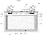
- FIGS. 2A and 2B are cross-sectional views illustrating secondary batteries 100 and 200 according to example embodiments of the present invention.
- the secondary battery 100 may include the electrode assembly 110 having a winding axis extending in a horizontal direction (i.e., in a direction substantially parallel with a lengthwise direction of the cap assembly 150).
- the secondary battery 200 may include an electrode assembly 210 having a winding axis extending in a vertical direction (i.e., in a direction substantially perpendicular to the lengthwise direction of the cap assembly 150).
- the electrode assembly may be a stacked electrode assembly, rather than a wound electrode assembly.
- the electrode assembly 110 may be formed by winding or stacking a stacked structure including a first electrode plate 111, a separator 113, and a second electrode plate 112, which are thin plates or layers.
- the first electrode plate 111 may operate as a negative electrode and the second electrode plate 112 may operate as a positive electrode, or vice versa.
- the first electrode plate 111 may be formed by coating a first active material, such as graphite or carbon, on a first electrode collector made of a metal foil, such as copper, a copper alloy, nickel, or a nickel alloy, and may include a first uncoated portion 111a that is not coated with the first active material.
- the second electrode plate 112 may be formed by coating a second active material, such as a transition metal oxide, on a second electrode collector made of a metal foil, such as aluminum or an aluminum alloy, and may include a second uncoated portion 112a that is not coated with the second electrode material.
- the separator 113 which is located between the first and second electrode plates 111 and 112, may prevent or substantially prevent short circuits between the first and second electrode plates 111 and 112, and may allow lithium ions to move.
- the separator 113 may include polyethylene, polypropylene, or a composite film of polyethylene and polypropylene.
- the separator 113 may be replaced by an inorganic solid electrolyte, such as a sulfide-based compound, an oxide-based compound, or a sulphate compound, such as to not necessitate a liquid- or gel-phase electrolyte solution.
- the first terminal 120 and the second terminal 130 electrically connected to the first electrode plate 111 and the second electrode plate 112, respectively, are located at opposite ends of the electrode assembly 110.
- the electrode assembly 110 may be accommodated in the can 140 with an electrolytic solution.
- the electrolytic solution may include an organic solvent, such as ethylene carbonate (EC), propylene carbonate (PC), diethyl carbonate (DEC), ethyl methyl carbonate (EMC), or dimethyl carbonate (DMC), and a lithium salt, such as LiPF 6 or LiBF 4 .
- an organic solvent such as ethylene carbonate (EC), propylene carbonate (PC), diethyl carbonate (DEC), ethyl methyl carbonate (EMC), or dimethyl carbonate (DMC)
- a lithium salt such as LiPF 6 or LiBF 4 .
- the first terminal 120 may be made of a metal and may be electrically connected to the first electrode plate 111.
- the first terminal 120 may include a first collector plate 121, a first terminal pillar 122, and a first terminal plate 124.
- the first collector plate 121 may be brought into contact with the first uncoated portion 111a protruding at an end of the electrode assembly 110.
- the first collector plate 121 may be welded to the first uncoated portion 111a.
- the first collector plate 121 may be substantially in an inverted L-shaped (" ⁇ ") configuration and may have a terminal hole 121a located in a top portion thereof.
- the first terminal pillar 122 may be inserted into the terminal hole 121a, followed by riveting and/or welding.
- the first collector plate 121 may be made of copper or a copper alloy.
- the first terminal pillar 122 penetrates the cap plate 151 to be described later and is electrically connected to the first collector plate 121 under the cap plate 151.
- a flange 122a may be located below the cap plate 151 to prevent or substantially prevent the first terminal pillar 122 from being dislodged from the cap plate 151.
- first terminal pillar 122 a portion of the first terminal pillar 122 positioned below the flange 122a is fitted into the first terminal hole 121a of the first collector plate 121, followed by riveting and/or welding.
- the first terminal pillar 122 may be electrically insulated from the cap plate 151.
- boundary regions of the upwardly exposed first terminal pillar 122 and the first terminal plate 124 may be welded to each other.
- a laser beam may be supplied to the boundary regions of the upwardly exposed first terminal pillar 122 and the first terminal plate 124 to melt the boundary regions, followed by cooling, thereby welding the boundary regions.
- the welded regions are designated by reference numeral 125 in FIG. 2A .
- a bus bar made of aluminum or an aluminum alloy may be welded to the first terminal plate 124.
- the second terminal 130 may also be made of a metal and may be electrically connected to the second electrode plate 112.
- the second terminal 130 may include a second collector plate 131, a second terminal pillar 132, and a second terminal plate 134.
- the second collector plate 131 may be brought into contact with the second uncoated portion 112a protruding at an end of the electrode assembly 110.
- the second collector plate 131 may be substantially in an inverted L-shaped (" ⁇ ") configuration and may have a terminal hole 131a located in a top portion thereof.
- the second terminal pillar 132 may be inserted into the terminal hole 131a and coupled thereto.
- the first collector plate 121 may be made of, for example, but is not limited to, aluminum or an aluminum alloy.
- the second terminal pillar 132 penetrates the cap plate 151 to be described later and is electrically connected to the second collector plate 131 under the cap plate 151.
- a flange 132a may be located below the cap plate 151 to prevent or substantially prevent the second terminal pillar 132 from being dislodged from the cap plate 151.
- a portion of the second terminal pillar 132 positioned below the flange 132a is fitted into the second terminal hole 131a of the second collector plate 131, followed by riveting and/or welding.
- the second terminal pillar 132 may be electrically insulated from the cap plate 151.
- the second terminal pillar 132 may be made of aluminum or an aluminum alloy.
- the second terminal plate 134 has a hole 134a.
- the second terminal plate 134 is coupled to the second terminal pillar 132. That is, the second terminal pillar 132 may be coupled to the hole 134a of the second terminal plate 134.
- the second terminal pillar 132 and the second terminal plate 134 may be riveted and/or welded to each other.
- boundary regions of the upwardly exposed second terminal pillar 132 and the second terminal plate 134 may be welded to each other.
- a laser beam may be supplied to the boundary regions of the upwardly exposed second terminal pillar 132 and the second terminal plate 134 to melt the boundary regions, followed by cooling, thereby welding the boundary regions.
- the welded regions are designated by reference numeral 135 in FIG. 2A .
- a bus bar made of aluminum or an aluminum alloy may be easily welded to the second terminal plate 134.
- the second terminal plate 134 may be electrically connected to the cap plate 151.
- the cap plate 151 and the can 140 which will be described below, may have the same polarity as the second terminal 130 (e.g., a positive polarity).
- the seal gasket 152 made of an insulating material may be located between each of the first terminal pillar 122 and the second terminal pillar 132 and the cap plate 151 at a bottom end of the cap plate 151 and may seal regions between each of the first terminal pillar 122 and the second terminal pillar 132 and the cap plate 151.
- the seal gasket 152 may prevent or substantially prevent external moisture from permeating into the secondary battery 100 or prevent or substantially prevent the electrolyte accommodated in the secondary battery 100 from being effused outside.
- the plug 153 may seal an electrolyte injection hole 151a of the cap plate 151.
- the safety vent 154 may be installed in a vent hole 151b of the cap plate 151 and has a notch configured to be openable at a preset pressure.
- the upper coupling member 155 may be located between each of the first terminal pillar 122 and the second terminal pillar 132 and the cap plate 151 at a top end of the cap plate 151. In addition, the upper coupling member 155 may closely contact the cap plate 151. In addition, the upper coupling member 155 may also closely contact and the seal gasket 152. In an embodiment, the upper coupling member 155 may insulate the first terminal pillar 122 and the second terminal pillar 132 from the cap plate 151. In some examples, the upper coupling member 155 located in the second terminal pillar 132 may electrically connect the second terminal plate 134 and the cap plate 151 to each other. Accordingly, the second terminal 130 may have the same polarity as the cap plate 151 and the can 140.
- the lower insulating member 156 may be located between each of the first collector plate 121 and the second collector plate 131 and the cap plate 151 and may prevent or substantially prevent an unnecessary short circuit from being generated. That is, the lower insulating member 156 may prevent or substantially prevent short circuits from being generated between the first collector plate 121 and the cap plate 151 and between the second collector plate 131 and the cap plate 151.
- the secondary battery 200 shown in FIG. 2B will now be described.
- the secondary battery 200 is different from the secondary battery 100 in terms of the construction of the electrode assembly 210 and the connection relationships between the electrode assembly 210 and each of the terminals 120 and 130.
- a first electrode tab 211a may be positioned between the electrode assembly 210 and a first terminal pillar 122 of a first terminal 120
- a second electrode tab 212a may be positioned between the electrode assembly 210 and a second terminal pillar 132 of a second terminal 130.
- the first electrode tab 211a may be extended from a top end of the electrode assembly 210 to a bottom end of the first terminal pillar 122 of the first terminal 120 to be electrically connected or welded to a planar flange 122a provided in the first terminal pillar 122.
- the second electrode tab 212a may be extended from a top end of the electrode assembly 210 to a bottom end of the second terminal pillar 132 of the second terminal 130 to be electrically connected or welded to a planar flange 132a provided in the second terminal pillar 132.
- the first electrode tab 211a may be either a first uncoated portion of the first electrode plate 211 of the electrode assembly 210, which is not coated with a first active material 211b, or a separate member connected to the first uncoated portion.
- the first uncoated portion may be made of the same material as the first electrode plate 211, and the separate member may be one selected from the group consisting of any of nickel, a nickel alloy, copper, a copper alloy, aluminum, an aluminum alloy, and equivalents thereof.
- the second electrode tab 212a may be either a second uncoated portion of the second electrode plate 212 of the electrode assembly 210, which is not coated with a second active material, or a separate member connected to the second uncoated portion.
- the second uncoated portion may be made of the same material as the second electrode plate 212, and the separate member may be one selected from the group consisting of any of aluminum, an aluminum alloy, nickel, a nickel alloy, copper, a copper alloy, and equivalents thereof.
- cans 140, 340, 440, 540, 640, and 740 manufactured by example methods, which will be described below, may be included in the secondary batteries 100 and 200 shown in FIGS. 1 , 2A , and 2B .
- FIGS. 3A to 3C are perspective views illustrating a method for manufacturing a secondary battery 100, 200 according to an example embodiment of the present invention.
- FIG. 3A shows a can 140 at an initial stage of manufacture.
- a substantially planar metal plate 140A having a uniform thickness may be provided using a blanking process and/or a notching process.
- the metal plate 140A may include a substantially rectangular bottom portion 141 having long sides and short sides, long side portions 142 and 143 horizontally extended from the respective long sides of the bottom portion 141, and short side portions 144 and 145 horizontally extended from the bottom portion 141 and the respective long side portions 142 and 143.
- one of the short side portions 144 may include a first short side portion 144a extended from the short side of the bottom portion 141 in a substantially triangular shape, a second short side portion 144b horizontally extended from an end of the long side portion 142, and a third short side portion 144c horizontally extended from an end of the long side portion 143.
- the second short side portion 144b may include an inclined periphery located on a region facing the first short side portion 144a
- the third short side portion 144c may also include an inclined periphery located on a region facing the first short side portion 144a.
- the second and third short side portions 144b and 144c may be matched or corresponding with the first short side portion 144a.
- the first to third short side portions together form a short side portion 144 of the case 140.
- the match or correspondence between the different short side portions forming a short side may be a form-fit or there may be a welding overlap between the respective short side portions to facilitate welding.
- the width of each of the long side portions 142 and 143 may be substantially equal to that of each of the long sides of the bottom portion 141.
- the width of the first short side portion 144a may be substantially equal to that of each of the short sides of the bottom portion 141.
- the overall width of the second and third short side portions 144b and 144c may be substantially equal to the width of each of the short sides of the bottom portion 141.
- the length of each of the long side portions 142 and 143 may be substantially equal to that of each of the short side portions 144 and 145.
- dashed lines indicate bending lines in a subsequent process to be described later.
- the metal plate 140A may include aluminum (Al), iron (Fe), copper (Cu), titanium (Ti), nickel (Ni), magnesium (Mg), chromium (Cr), manganese (Mn), zinc (Zn), or alloys of these elements.
- the metal plate 140A may include nickel (Ni) plated iron (Fe) or SUS (e.g., SUS 301, SUS 304, SUS 305, SUS 316L, or SUS 321).
- the metal plate 140A may have a thickness in a range from approximately 0.1 mm to approximately 10 mm, and a deviation in the thickness of the metal plate 140A in all areas may be in a range from approximately 0.1% to approximately 1%. Therefore, embodiments of the present invention may provide the can 140 that is relatively thin and has a small thickness deviation, compared to a conventional can.
- the metal plate 140A may be preprocessed to facilitate a bending process and/or a welding process, which will be described below.
- the metal plate 140A may be subjected to annealing treatment performed in a gas atmosphere (e.g., a predetermined gas atmosphere) and a temperature range (e.g., a predetermined temperature range) for a period of time (e.g., a predetermined period of time).
- the annealing treatment may be performed in an atmosphere of inert gas, such as argon (Ar) or nitrogen (N 2 ) at a temperature range from approximately 300 °C to approximately 1000 °C for approximately 10 seconds to approximately 60 minutes.
- the annealing treatment may increase the elastic modulus of the metal plate 140A by approximately 5% to approximately 60%. Accordingly, the bending process of the metal plate 140A, which will later be described, may be easily performed, and occurrence of a spring-back phenomenon can be minimized or reduced, particularly after the bending process.
- the metal plate 140A may have a substantially planar top surface and a substantially planar bottom surface.
- the top surface of the metal plate 140A may be subjected to insulation treatment.
- a thin insulation film may be located on the top surface of metal plate 140A by forming a thin oxide layer (e.g., an anodizing layer) through a metal oxidation process or coating or laminating an insulation resin (e.g., polyimide, polypropylene, or polyethylene).
- the top surface of the metal plate 140A may correspond to the interior surface of the can 140, and the bottom surface of the metal plate 140A may correspond to the exterior surface of the can 140.
- FIG. 3B shows a can 140 at a later stage of manufacture.
- the metal plate 140A may be bent in a shape (e.g., a predetermined shape).
- the metal plate 140A may be bent in a predetermined shape after it is fixed by a bending machine or a press mold.
- the long side portions 142 and 143 bent and extended from the respective long sides of the bottom portion 141 in a substantially perpendicular direction, and the short side portions 144 and 145 bent and extended from the bottom portion 141 and the long side portions 142 and 143 in a substantially perpendicular direction may be provided as the result of the bending process.
- the long side portions 142 and 143 may be bent approximately 90 degrees from the long sides of the bottom portion 141 to be extended
- the short side portions 144 and 145 may be bent approximately 90 degrees from the short sides of the bottom portion 141 to be extended and may be bent approximately 90 degrees from the long side portions 142 and 143 to be extended.
- the first short side portion 144a, the second short side portion 144b, and the third short side portion 144c may be positioned to face one another, and their peripheries may be matched and brought into contact with one another.
- a vertex angle defined between the upper periphery of the first short side portion 144a and the short side of the bottom portion 141 may be in a range from approximately 40 degrees to approximately 50 degrees, and, in an embodiment, 45 degrees.
- the vertex angle of the first short side portion 144a facing the second and third short side portions 144b and 144c may be in a range from approximately 80 degrees to approximately 100 degrees, and, in an embodiment, 90 degrees.
- a vertex at which the bottom portion 141, the end of the long side portion 142, the first short side portion 144a, and the second short side portion 144b meet, and a vertex at which the bottom portion 141, the end of the long side portion 143, the first short side portion 144a, and the third short side portion 144c meet, may be bent in a substantially round shape.
- FIG. 3B shows an example in which the short side portions 144 and 145 are bent from the long side portions 142 and 143, respectively. That is, FIG. 3B shows an example in which the long side portions 142 and 143 have yet to be bent from the bottom portion 141.
- FIG. 3C shows the can 140 at a later stage of manufacture.
- a welding process may be performed.
- welding portions 146 may be provided in the short side portions 144 and 145.
- the welding portions 146 may include a first welding portion 146a located at a boundary region between the first short side portion 144a and the second short side portion 144b, a second welding portion 146b located at a boundary region between the first short side portion 144a and the third short side portion 144c, and a third welding portion 146c located at a boundary region between the second short side portion 144b and the third short side portion 144c.
- first welding portion 146a may be at an acute angle with respect to a short side of the bottom portion 141 at a vertex, where the bottom portion 141, an end of the long side portion 142, and the first short side portion 144a meet
- second welding portion 146b may be at an acute angle with respect to the short side of the bottom portion 141 at a vertex, where the bottom portion 141, the end of the long side portion 143, and the first short side portion 144a meet.
- the third welding portion 146c may be extended from a bottom end of the second and third short side portions 144b and 144c to a top end (i.e., an opening 147) of the second and third short side portions 144b and 144c.
- first and second welding portions 146a and 146b may be consecutively formed, and the third welding portion 146c may then be formed, or vice versa.
- the welding process may be performed on the first welding portion 146a, the third welding portion 146c, and the second welding portion 146b in that order, or the welding order may be reversed.
- the welding process performed on the third welding portion 146c may be started from the bottom end and may be terminated at the top end, or vice versa.
- the first, second, and third welding portions 146a, 146b, and 146c may include a butt joint structure, a lap joint structure, an overlay joint structure, or an edge joint structure.
- the welding portions 146 may be in a substantially inverted Y-shaped (" ") configuration.
- the welding portions 146 may be provided to have a solid-line shape. Therefore, the first short side portion 144a may be securely fixed to the second and third short side portions 144b and 144c due to the first and second welding portions 146a and 146b, and the second and third short side portions 144b and 144c may be securely fixed to each other by the third welding portion 146c.
- first and second welding portions 146a and 146b connected to each other may be shaped as straight lines having at least one vertex
- the third welding portion 146c may be shaped as a straight line extending from the vertex, where the first and second welding portions 146a and 146b meet, to the opening 147.
- a vertex angle defined between the first welding portion 146a and the second welding portion 146b may be in a range from approximately 80 degrees to approximately 100 degrees, and, in an embodiment, 90 degrees.
- an angle in a range from approximately 40 degrees to approximately 50 degrees, and, in an embodiment, 45 degrees, may be defined between the first welding portion 146a and the short side of the bottom portion 141, and an angle in a range from approximately 40 degrees to approximately 50 degrees, and, in an embodiment, 45 degrees, may be defined between the second welding portion 146b and the short side of the bottom portion 141.
- one or more embodiments of the present invention provide the can 140 configured such that the first short side portion 144a is bent and extended from the bottom portion 141, the second and third short side portions 144b and 144c are bent and extended from the long side portions 142 and 143, and the first, second, and third short side portions 144a,144b, and 144c are connected to one another through the first, second, and third welding portions 146a, 146b, and 146c to define a single short side portion 144, thereby providing the can 140 having increased bending and welding workability and improved sealing efficiency to prevent or substantially prevent leakage of electrolyte.
- first short side portion 144a is bent and extended from the corresponding bottom portion 141
- a welding process is not necessarily performed between the bottom portion 141 corresponding to the first short side portion 144a and the first short side portion 144a.
- second and third short side portions 144b and 144c are bent and extended from the corresponding long side portions 142 and 143, respectively, a welding process is not necessarily performed between the long side portions 142 and 143 corresponding to the second and third short side portions 144b and 144c and the second and third short side portions 144b and 144c.
- These configurations may be commonly applied between the long side portions 142 and 143 and another short side portion 145.
- a temporary welding portion may first be provided at a boundary region between the first short side portion 144a and the second short side portion 144b, a boundary region between the first short side portion 144a and the third short side portion 144c, and/or a boundary region between the second short side portion 144b and the third short side portion 144c.
- the temporary welding portion may include multiple temporary welding portions spaced apart from one another.
- the temporary welding portions may be provided to have substantially dotted-line shapes. The temporary welding portions may prevent or substantially prevent a spring-back phenomenon from occurring to the long side portions 142 and 143, the short side portions 144 and 145, and the bottom portion 141.
- the temporary welding portions can securely fix the long side portions 142 and 143 and the short side portions 144 and 145 to each other. Accordingly, the main welding portions 146 (i.e., the welding portions 146) may be easily provided.
- the temporary welding portions may be provided by ultrasonic welding or resistance welding, as well as laser welding.
- FIGS. 4A to 4C are perspective views illustrating a method for manufacturing a secondary battery 100, 200 according to an example embodiment of the present invention.
- FIG. 4A shows a can 340 at an initial stage of manufacture.
- a substantially planar metal plate 340A having a uniform thickness may be provided using a blanking process and/or a notching process.
- the metal plate 340A may include a substantially rectangular bottom portion 341 having long sides and short sides, long side portions 342 and 343 horizontally extended from the respective long sides of the bottom portion 341, and short side portions 344 and 345 horizontally extended from the bottom portion 341 and the respective long side portions 342 and 343.
- one of the short side portions 344 may include a first short side portion 344a extended from the short side of the bottom portion 341 in a substantially trapezoidal shape, a second short side portion 344b horizontally extended from an end of the long side portion 342, and a third short side portion 344c horizontally extended from an end of the long side portion 343.
- the second short side portion 344b may have a periphery inclined and bent at a region facing the first short side portion 344a
- the third short side portion 344c may also have a periphery inclined and bent at a region facing the first short side portion 344a.
- widths of the long side portions 342 and 343 may be substantially equal to a width of the bottom portion 341.
- widths of the short side portions 344 and 345 may be substantially equal to a width of each of the short sides of the bottom portion 341.
- the overall width of the second and third short side portions 344b and 344c may be substantially equal to the width of each of the short sides of the bottom portion 341.
- the length of each of the long side portions 342 and 343 may be substantially equal to that of each of the short side portions 344 and 345.
- the first short side portion 344a bent and extended from the short side of the bottom portion 341 has a substantially trapezoidal shape, but it is to be understood by one skilled in the art that the first short side portion 344a may have a square or rectangular shape.
- FIG. 4B shows the can 340 at a later stage of manufacture.
- the metal plate 340A may be bent in a shape (e.g., a predetermined shape).
- the metal plate 340A may be bent in a predetermined shape after it is fixed by a bending machine or a press mold.
- the long side portions 342 and 343 bent and extended from the respective long sides of the bottom portion 341 in a substantially perpendicular direction, and the short side portions 344 and 345 bent and extended from the bottom portion 341 and the long side portions 342 and 343 in a substantially perpendicular direction may be provided as the result of the bending process. That is, the long side portions 342 and 343 may be bent approximately 90 degrees from the long sides of the bottom portion 341 to be extended, and the short side portions 344 and 345 may be bent approximately 90 degrees from the short sides of the bottom portion 341 to be extended and may be bent approximately 90 degrees from the long side portions 342 and 343 to be extended.
- first short side portion 344a may be bent approximately 90 degrees from the short side of the bottom portion 341 to be extended
- the second short side portion 344b may be bent approximately 90 degrees from an end of the long side portion 342 to be extended
- the third short side portion 344c may be bent approximately 90 degrees from an end of the long side portion 343 to be extended. Therefore, the first short side portion 344a, the second short side portion 344b, and the third short side portion 344c may be positioned to face one another and their peripheries may contact one another.
- an angle defined between the periphery of the first short side portion 344a and the short side of the bottom portion 341 may be in a range from approximately 40 degrees to approximately 50 degrees, and, in an embodiment, 45 degrees.
- FIG. 4B shows an example in which the short side portions 344 and 345 are bent from the long side portions 342 and 343.
- FIG. 4C shows the can 340 at a later stage of manufacture.
- a welding process may be performed.
- welding portions 346 may be provided in the short side portions 344 and 345.
- the welding portions 346 may include a first welding portion 346a located at a boundary region between the first short side portion 344a and the second short side portion 344b, a second welding portion 346b located at a boundary region between the first short side portion 344a and the third short side portion 344c, and a third welding portion 346c located at a boundary region between the second short side portion 344b and the third short side portion 344c.
- the first welding portion 346a may be at an acute angle with respect to the short side of the bottom portion 341 at a vertex, where the bottom portion 341, an end of the long side portion 342 and the first short side portion 344a meet, and may be extended to be bent
- the second welding portion 346b may be at an acute angle with respect to the short side of the bottom portion 341 at a vertex, where the bottom portion 341, an end of the long side portion 343, and the first short side portion 344a meet, and may be extended to be bent.
- the third welding portion 346c may be extended from bottom ends of the second and third short side portions 344b and 344c to top ends (i.e., an opening 347) of the second and third short side portions 344b and 344c.
- the first and second welding portions 346a and 346b may be consecutively formed, and the third welding portion 346c may then be formed, or vice versa.
- the welding process performed on the third welding portion 346c may be started from a bottom end of the third welding portion 346c and may be terminated at the top end, or vice versa.
- the first, second, and third welding portions 346a, 346b, and 346c may include a butt joint structure, a lap joint structure, an overlay joint structure, or an edge joint structure.
- the welding portions 346 may be in a substantially " " shaped configuration.
- the welding portions 346 may overlap with temporary welding portions and may be shaped as solid lines. Therefore, the first short side portion 344a may be securely fixed to the second and third short side portions 344b and 344c by the first and second welding portions 346a and 346b, and the second and third short side portions 344b and 344c may be securely fixed to each other by the third welding portion 346c.
- first and second welding portions 346a and 346b may be shaped as straight lines having at least two vertices
- the third welding portion 346c may be shaped as a straight line extending from a side where the first and second welding portions 346a and 346b meet to the opening 347.
- first short side portion 344a is bent and extended from the corresponding bottom portion 341
- a welding process is not necessarily performed between the bottom portion 341 corresponding to the first short side portion 344a and the first short side portion 344a.
- second and third short side portions 344b and 344c are bent and extended from the corresponding long side portions 342 and 343, respectively, a welding process is not necessarily performed between the long side portions 342 and 343 corresponding to the second and third short side portions 344b and 344c and the second and third short side portions 344b and 344c.
- temporary welding portions may first be provided at a boundary region between the first short side portion 344a and the second short side portion 344b, a boundary region between the first short side portion 344a and the third short side portion 344c, and/or a boundary region between the second short side portion 344b and the third short side portion 344c.
- the temporary welding portions may prevent or substantially prevent a spring back phenomenon from occurring to the long side portions 342 and 343, the short side portions 344 and 345, and the bottom portion 341.
- the temporary welding portions can securely fix the long side portions 342 and 343 and the short side portions 344 and 345 to each other. Accordingly, the main welding portions 346 (i.e., the welding portions 346) may be easily provided.
- FIGS. 5A to 5D are partial perspective views illustrating cans 440, 540, 640, and 740 included in a secondary battery according to example embodiments of the present invention.
- short side portions 444 of the can 440 may include a first short side portion 444a bent and extended from the bottom portion 141 in a substantially semicircular shape, a second short side portion 444b bent and extended from an end of the long side portion 142, and a third short side portion 444c bent and extended from an end of the long side portion 143.
- the second short side portion 444b and the third short side portion 444c may have peripheries matched with the substantially semicircular first short side portion 444a.
- the first, second, and third short side portions 444a, 444b, and 444c may be integrally formed by welding portions 446 to define a single short side portion 444.
- the welding portions 446 may include a first welding portion 446a located at a boundary region between the first short side portion 444a and the second short side portion 444b, a second welding portion 446b located at a boundary region between the first short side portion 444a and the third short side portion 444c, and a third welding portion 446c located at a boundary region between the second short side portion 444b and the third short side portion 444c.
- the first and second welding portions 446a and 446b may have a substantially semicircular shape
- the third welding portion 446c may be shaped as a straight line extending from a region where the first and second welding portions 446a and 446b meet to a top opening of the can 440.
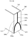
- short side portions 544 of the can 540 may include a substantially vertically semi-elliptical first short side portion 544a bent and extended from the bottom portion 141, a second short side portion 544b bent and extended from an end of the long side portion 142, and a third short side portion 544c bent and extended from an end of the long side portion 143.
- the second short side portion 544b and the third short side portion 544c may have peripheries matched with the substantially vertically semi-elliptical first short side portion 544a.
- the first, second, and third short side portions 544a, 544b, and 544c may be integrally formed by welding portions 546 to define a single short side portion 544.
- the welding portions 546 may include a first welding portion 546a located at a boundary region between the first short side portion 544a and the second short side portion 544b, a second welding portion 546b located at a boundary region between the first short side portion 544a and the third short side portion 544c, and a third welding portion 546c located at a boundary region between the second short side portion 544b and the third short side portion 544c.
- the first and second welding portions 546a and 546b may have a substantially vertically semi-elliptical shape
- the third welding portion 546c may be shaped as a straight line extending from a region where the first and second welding portions 546a and 546b meet to a top opening of the can 540.
- the vertically semi-elliptical shape means that the major axis of an ellipse extends in a vertical direction.
- short side portions 644 of the can 640 may include a substantially horizontally semi-elliptical first short side portion 644a bent and extended from the bottom portion 141, a second short side portion 644b bent and extended from an end of the long side portion 142, and a third short side portion 644c bent and extended from an end of the long side portion 143.
- the second short side portion 644b and the third short side portion 644c may have peripheries matched with the substantially horizontally semi-elliptical first short side portion 644a.
- the first, second, and third short side portions 644a, 644b, and 644c may be integrally formed by welding portions 646 to define a single short side portion 644.
- the welding portions 646 may include a first welding portion 646a located at a boundary region between the first short side portion 644a and the second short side portion 644b, a second welding portion 646b located at a boundary region between the first short side portion 644a and the third short side portion 644c, and a third welding portion 646c located at a boundary region between the second short side portion 644b and the third short side portion 644c.
- the first and second welding portions 646a and 646b may have a substantially horizontally semi-elliptical shape
- the third welding portion 646c may be shaped as a straight line extending from a region where the first and second welding portions 646a and 646b meet to a top opening of the can 640.
- the horizontally semi-elliptical shape means that the major axis of an ellipse extends in a horizontal direction.
- short side portions 744 of the can 740 may include a substantially quadrangular (rectangular or square) first short side portion 744a bent and extended from the bottom portion 141, a second short side portion 744b bent and extended from an end of the long side portion 142, and a third short side portion 744c bent and extended from an end of the long side portion 143.
- the second short side portion 744b and the third short side portion 744c may have peripheries matched or corresponding with the substantially quadrangular first short side portion 744a.
- the first, second, and third short side portions 744a, 744b, and 744c may be integrally formed by welding portions 746 to define a single short side portion 744.
- the welding portions 746 may include a first welding portion 746a located at a boundary region between the first short side portion 744a and the second short side portion 744b, a second welding portion 746b located at a boundary region between the first short side portion 744a and the third short side portion 744c, and a third welding portion 746c located at a boundary region between the second short side portion 744b and the third short side portion 744c.
- first and second welding portions 746a and 746b may have a substantially quadrangular shape (e.g., three sides of a quadrangle), and the third welding portion 746c may be shaped as a straight line extending from a region where the first and second welding portions 746a and 746b meet to a top opening of the can 740.
- first welding portion 746a may be provided at a boundary region between an end of the long side portion 142 and the first short side portion 744a and a boundary region between the first short side portion 744a and the second short side portion 744b
- second welding portion 746b may be provided at a boundary region between an end of the long side portion 143 and the first short side portion 744a and a boundary region between the first short side portion 744a and the third short side portion 744c.
- the regions of the first and second welding portions located at the boundary region between the end of the long side portion 142 and the first short side portion 744a and a boundary region between the end of the long side portion 143 and the first short side portion 744a may include an edge joint structure.
- FIG. 6 is a plan view illustrating a configuration of welding portions 146 provided in the can 140 of the secondary battery 100, 200 according to an example embodiment of the present invention.
- the welding portions 146 may include multiple welding beads.
- the multiple welding beads may overlap with one another from the bottom portion 141 of the can 140 to the opening 147 (i.e., the cap assembly 150). That is, since laser beams move from the bottom portion 141 of the can 140 to the opening 147 (that is, from the bottom ends to the top ends of the short side portions 144a and 144b), circular peripheries of the multiple welding beads may face substantially bottom ends (i.e., the bottom portion 141).
- the welding portions 146 include the multiple overlapping welding portions, such that pin holes, blow holes, and/or worm holes may not be located in the welding portions 146.
- the welding portions 146 are located to face the bottom portion 141 of the can 140 from the opening 147 of the can 140, the circular peripheries of the multiple welding beads may face substantially top ends (i.e., the opening 147).
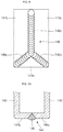
- FIGS. 7A to 7E are cross-sectional views illustrating configurations of welding portions provided in the can of the secondary battery 100, 200 according to example embodiments of the present invention.
- a welding portion 146 may be provided between a second short side portion 144b extended from an end of a long side portion 142 and a third short side portion 144c extended from an end of a long side portion 143.
- the welding portion 146 may include a butt joint structure. That is, the welding portion 146 may be provided in a butted state in which an end of the second short side portion 144b is matched with an end of the third short side portion 144c to be brought into contact with each other.
- the welding portion 146 may be provided not only outside but also inside (i.e., inside of the can 140).
- a welding portion 146A may be provided between the second short side portion 144b extended from an end of the long side portion 142 and the third short side portion 144c extended from an end of the long side portion 143.
- the welding portion 146A may include a lap joint structure. That is, the welding portion 146A may be provided in a state in which the second short side portion 144b and the third short side portion 144c overlap with each other. In an embodiment, the welding portion 146A may be provided not only outside but also inside (i.e., inside of the can 140).
- a welding portion 146B may be provided between the first short side portion 144a extended from the bottom portion 141 and the second, third short side portion 144b, 144c.
- the welding portion 146B may include a lap joint structure. That is, the welding portion 146B may be provided in a state in which the first short side portion 144a and the second, third short side portion 144b, 144c overlap with each other.
- the first short side portion 144a may overlap with the second, third short side portion 144b, 144c from an exterior surface of the second, third short side portion 144b, 144c.
- the welding portion 146B may be provided not only outside but also inside (i.e., inside of the can 140).
- a welding portion 146C may be provided in a state in which the first short side portion 144a overlaps with an interior surface of the second, third short side portion 144b, 144c.
- the welding portion 146C may be provided not only outside but also inside (i.e., inside of the can 140).
- welding portions 846a and 846b may be provided between the second short side portion 144b extended from an end of the long side portion 142 and the third short side portion 144c extended from an end of the long side portion 143.
- the welding portions 846a and 846b may include a single-side overlay joint structure having a cover plate 836.
- the welding portions 846a and 846b may be provided not only outside but also inside (i.e., inside of the can 140). Therefore, the welding portions 846a and 846b may also include double-side overlay joint structure.
- the can according to embodiments of the present invention may include a wide variety of joint structures for welding portions, and the can may have improved sealing efficiency to prevent or substantially prevent leakage of electrolyte.
Landscapes
- Chemical & Material Sciences (AREA)
- Chemical Kinetics & Catalysis (AREA)
- Electrochemistry (AREA)
- General Chemical & Material Sciences (AREA)
- Engineering & Computer Science (AREA)
- Materials Engineering (AREA)
- Manufacturing & Machinery (AREA)
- Inorganic Chemistry (AREA)
- Sealing Battery Cases Or Jackets (AREA)
- Connection Of Batteries Or Terminals (AREA)
Abstract
Description
- Aspects of embodiments of the present invention relate to a secondary battery.
- A battery may be classified as a prismatic type, a cylindrical type, a pouch type, etc., according to the shape of a can, or case. A prismatic or cylindrical battery may be manufactured by inserting an electrode assembly having a positive electrode, a negative electrode, and a separator into a metal can and sealing the electrode assembly, while a pouch type battery may be manufactured by enclosing an electrode assembly using an aluminum foil coated with an insulator.
- Traditional battery can manufacturing methods may include a deep drawing process, an impact process, and so on. In an example, the deep drawing process is performed such that a sheet-shaped metal plate is placed on a molding die, and punching operations are performed on the metal plate about ten times using a punch, thereby completing the can. In another example, the impact process is performed such that a slug in the form of a billet is placed on a molding die and a strong punching operation is performed on the slug about one time using a punch, thereby completing the can. The impact process can reduce the number of processing steps, thereby lowering the manufacturing cost.
- However, the conventional deep drawing process and the conventional impact process are both limited in reducing a can thickness due to the respective manufacturing process characteristics and may have a large deviation in the thickness of the can according to the area of the can. In addition, the conventional deep drawing process and the conventional impact process are problematic in that the manufacturing cost of the battery can is quite high.
- The above information disclosed in this Background section is only for enhancement of understanding of the background of the described technology and, therefore, it may contain information that does not form the prior art that is already known in this country to a person of ordinary skill in the art.
- According to an aspect of embodiments of the present invention, a secondary battery may have substantially no thickness deviation in various areas of a can by reducing the thickness of the can and increasing dimensional accuracy.
- According to another aspect of embodiments of the present invention, a secondary battery may have increased capacity relative to the battery size and may have reduced manufacturing cost by minimizing or reducing the thickness of the can.
- According to one or more embodiments of the present invention, a secondary battery includes: an electrode assembly; a case accommodating the electrode assembly; and a cap assembly coupled to the case to seal the case, wherein the case includes a bottom portion, long side portions bent and extended from the bottom portion, a first short side portion bent and extended from the bottom portion, and second short side portions bent and extended from the long side portions, and the first short side portion and the second short side portions are connected to one another to define a short side portion.
- The first short side portion may have a shape of a triangle, a rectangle, a trapezoid, a semicircle, or a semi-ellipse, and the second short side portions may be configured to correspond with the first short side portion.
- The second short side portions may be connected to each other.
- The short side portion may include welding portions, and the welding portions may include a first welding portion located between the first short side portion and the second short side portions, and a second welding portion located between the second short side portions.
- The first welding portion and the second welding portion may be connected to each other.
- The first welding portion may be shaped as a straight line having at least one vertex, and the second welding portion may be shaped as a straight line extending from the first welding portion.
- The first welding portion may have a vertex angle in a range from 80 degrees to 100 degrees.
- The second welding portion may be extended from a vertex or a side of the first welding portion.
- The first welding portion may be shaped as a curve, and the second welding portion may be shaped as a straight line extending from the first welding portion.
- A welding portion of the welding portions may include a butt joint structure, a lap joint structure, an overlay joint structure, or an edge joint structure.
- The butt joint structure may be configured to provide the welding portion in a state in which an end of the first short side portion and an end of the second short side portions are in contact with each other.
- The lap joint structure may be configured to provide the welding portion in a state in which the first short side portion and the second short side portions overlap with each other.
- The overlay joint structure may be configured to provide the welding portion in a state in which a cover plate is attached to the first short side portion and the second short side portions.
- A welding portion of the welding portions may include multiple welding beads, and the multiple welding beads include circular peripheries facing the bottom portion.
- The first short side portion may extend from both end portions of the bottom portion, the second short side portions may extend from both ends of the long side portions, and the short side portion may be defined on both sides of the bottom portion and the long side portions.
- As described above, in a secondary battery according to one or more embodiments of the present invention, the thickness of a can may be reduced, and there may be substantially no thickness deviation in each area of the can by increasing dimensional accuracy. In some examples, a can having a top opening may be provided by performing blanking and/or notching, bending, and welding processes on a metal plate. In such a way, the can may be manufactured using a metal plate through bending and welding processes, rather than a conventional process, e.g., deep drawing or impacting, thereby determining the thickness of the can depending on the thickness of the metal plate. Therefore, the can may have a reduced thickness, compared to the conventional can, and may have a uniform thickness in various areas of the can (e.g., a bottom portion, long side portions, and short side portions). Accordingly, when a cap assembly is welded to the can, the cap assembly may uniformly contact corresponding areas of the can, thereby preventing or substantially preventing a welding failure from occurring to the cap assembly.
- In addition, in the secondary battery according to one or more embodiments of the present invention, a capacity relative to the battery size may be increased and the manufacturing cost may be reduced by minimizing or reducing the thickness of a can. That is, as described above, the metal plate may be bent and welded to provide the can, thereby allowing the can to have a reduced thickness, compared to a conventional can. Accordingly, the secondary battery may have a larger charge/discharge capacity than a conventional secondary battery, even if the secondary battery according to the present invention has a same size as the conventional battery.
-
-
FIG. 1 is a perspective view illustrating a secondary battery according to an example embodiment of the present invention. -
FIGS. 2A and2B are cross-sectional views illustrating secondary batteries according to example embodiments of the present invention. -
FIGS. 3A to 3C are perspective views illustrating a method for manufacturing a secondary battery according to an example embodiment of the present invention. -
FIGS. 4A to 4C are perspective views illustrating a method for manufacturing a secondary battery according to an example embodiment of the present invention. -
FIGS. 5A to 5D are partial perspective views illustrating a method for manufacturing a secondary battery according to an example embodiment of the present invention. -
FIG. 6 is a plan view illustrating a configuration of a welding portion provided in a can of a secondary battery according to an example embodiment of the present invention. -
FIGS. 7A to 7E are cross-sectional views illustrating configurations of welding portions provided in a can of a secondary battery according to example embodiments of the present invention. - Herein, some example embodiments of the present invention will be described in further detail.
- Various embodiments of the present invention may be embodied in many different forms and should not be construed as being limited to the example embodiments set forth herein. Rather, these example embodiments of the disclosure are provided so that this disclosure will be thorough and complete and will convey inventive concepts of the disclosure to those skilled in the art.
- In addition, in the accompanying drawings, sizes or thicknesses of various components may be exaggerated for brevity and clarity. Like numbers refer to like elements throughout. In addition, it is to be understood that when an element A is referred to as being "connected to" an element B, the element A may be directly connected to the element B or one or more intervening elements C may be present, and the element A and the element B may be indirectly connected to each other.
- The terminology used herein is for the purpose of describing particular embodiments and is not intended to be limiting of the disclosure. As used herein, the singular forms are intended to include the plural forms as well, unless the context clearly indicates otherwise. It is to be further understood that the terms "comprise or include" and/or "comprising or including," when used in this specification, specify the presence of stated features, numbers, steps, operations, elements, and/or components, but do not preclude the presence or addition of one or more other features, numbers, steps, operations, elements, components, and/or groups thereof.
- It is to be understood that, although the terms "first," "second," etc. may be used herein to describe various members, elements, regions, layers, and/or sections, these members, elements, regions, layers, and/or sections should not be limited by these terms. These terms are used to distinguish one member, element, region, layer, and/or section from another. Thus, for example, a first member, a first element, a first region, a first layer, and/or a first section discussed below could be termed a second member, a second element, a second region, a second layer, and/or a second section without departing from the teachings of the present disclosure.
- Spatially relative terms, such as "below," "beneath," "lower," "above," "upper," and the like, may be used herein for ease of description to describe one element or feature's relationship to another element(s) or feature(s) as illustrated in the figures. It is to be understood that the spatially relative terms are intended to encompass different orientations of the device in use or operation in addition to the orientation depicted in the figures. For example, if the device in the figures is turned over, elements described as "below" or "beneath" other elements or features would then be oriented "on" or "above" the other elements or features. Thus, the exemplary term "below" can encompass both an orientation of above and below.
- The term "welding portion" used throughout this specification may be referred to as a temporary welding portion and/or a welding portion in some cases, which is for representing the welding sequence and function but is not intended to limit the invention. In addition, the term "welding" as used herein mainly means laser welding, and examples of a laser used for welding may include, but are not limited to, CO2 laser, fiber laser, disk laser, semiconductor laser, and/or yttrium aluminum garnet (YAG) laser. In addition, the terms "second short side portion" and "third short side portion" may be referred to as second short side portions, in some cases. Thus, a plural "second short side portions" may refer together to "a second short side portion" and a "third short side portion".
- Unless otherwise defined, all terms used herein (including technical or scientific terms) have the same meanings as those generally understood by those skilled in the art to which the inventive concept pertains. Such terms as those defined in a generally used dictionary are to be interpreted as having meanings equal to the contextual meanings in the relevant field of art, and are not to be interpreted as having idealized or excessively formal meanings unless clearly defined herein.
-
FIG. 1 is a perspective view illustrating a secondary battery according to an example embodiment of the present invention. In the example shown inFIG. 1 , asecondary battery 100 may include an electrode assembly 110 (110 and 210 in the examples shown inFIGS. 2A and2B ), afirst terminal 120, asecond terminal 130, a can, or case, 140, and acap assembly 150. - In some examples, the
can 140 may be provided by blanking and/or notching, bending, and welding a metal plate, and may have a substantially hexahedral shape having an opening through which theelectrode assembly 110 is inserted and placed and thecap assembly 150 is mounted. In some examples, thecan 140 may include arectangular bottom portion 141 having long sides and short sides,long side portions bottom portion 141 to thecap assembly 150, andshort side portions bottom portion 141 and thelong side portions - In
FIG. 1 , thecan 140 and thecap assembly 150 assembled to each other are illustrated, such that the opening, which is a substantially opened part of a region corresponding to thecap assembly 150, is not illustrated inFIG. 1 . In an embodiment, the interior surface of thecan 140 is subjected to insulation treatment such that thecan 140 is insulated from theelectrode assembly 110, thefirst terminal 120, thesecond terminal 130, and thecap assembly 150. -
FIGS. 2A and2B are cross-sectional views illustratingsecondary batteries FIG. 2A , thesecondary battery 100 may include theelectrode assembly 110 having a winding axis extending in a horizontal direction (i.e., in a direction substantially parallel with a lengthwise direction of the cap assembly 150). In the example shown inFIG. 2B , thesecondary battery 200 may include anelectrode assembly 210 having a winding axis extending in a vertical direction (i.e., in a direction substantially perpendicular to the lengthwise direction of the cap assembly 150). In some examples, the electrode assembly may be a stacked electrode assembly, rather than a wound electrode assembly. - The
secondary battery 100 shown inFIG. 2A will now be described. Theelectrode assembly 110 may be formed by winding or stacking a stacked structure including afirst electrode plate 111, aseparator 113, and asecond electrode plate 112, which are thin plates or layers. In some examples, thefirst electrode plate 111 may operate as a negative electrode and thesecond electrode plate 112 may operate as a positive electrode, or vice versa. In some examples, thefirst electrode plate 111 may be formed by coating a first active material, such as graphite or carbon, on a first electrode collector made of a metal foil, such as copper, a copper alloy, nickel, or a nickel alloy, and may include a firstuncoated portion 111a that is not coated with the first active material. In some examples, thesecond electrode plate 112 may be formed by coating a second active material, such as a transition metal oxide, on a second electrode collector made of a metal foil, such as aluminum or an aluminum alloy, and may include a seconduncoated portion 112a that is not coated with the second electrode material. In some examples, theseparator 113, which is located between the first andsecond electrode plates second electrode plates separator 113 may include polyethylene, polypropylene, or a composite film of polyethylene and polypropylene. In an embodiment, theseparator 113 may be replaced by an inorganic solid electrolyte, such as a sulfide-based compound, an oxide-based compound, or a sulphate compound, such as to not necessitate a liquid- or gel-phase electrolyte solution. Thefirst terminal 120 and thesecond terminal 130 electrically connected to thefirst electrode plate 111 and thesecond electrode plate 112, respectively, are located at opposite ends of theelectrode assembly 110. In some examples, theelectrode assembly 110 may be accommodated in thecan 140 with an electrolytic solution. In some examples, the electrolytic solution may include an organic solvent, such as ethylene carbonate (EC), propylene carbonate (PC), diethyl carbonate (DEC), ethyl methyl carbonate (EMC), or dimethyl carbonate (DMC), and a lithium salt, such as LiPF6 or LiBF4. In some examples, if the inorganic solid electrolyte is used, the electrolytic solution may be omitted. - The
first terminal 120 may be made of a metal and may be electrically connected to thefirst electrode plate 111. In some examples, thefirst terminal 120 may include afirst collector plate 121, a firstterminal pillar 122, and a firstterminal plate 124. In some examples, thefirst collector plate 121 may be brought into contact with the firstuncoated portion 111a protruding at an end of theelectrode assembly 110. Thefirst collector plate 121 may be welded to the firstuncoated portion 111a. In some examples, thefirst collector plate 121 may be substantially in an inverted L-shaped ("┌") configuration and may have aterminal hole 121a located in a top portion thereof. In some examples, the firstterminal pillar 122 may be inserted into theterminal hole 121a, followed by riveting and/or welding. In some examples, thefirst collector plate 121 may be made of copper or a copper alloy. In some examples, the firstterminal pillar 122 penetrates thecap plate 151 to be described later and is electrically connected to thefirst collector plate 121 under thecap plate 151. In addition, in some examples, while the firstterminal pillar 122 is upwardly protruded and extended to an upper portion of thecap plate 151 by a length (e.g., a predetermined length), aflange 122a may be located below thecap plate 151 to prevent or substantially prevent the firstterminal pillar 122 from being dislodged from thecap plate 151. In an embodiment, a portion of the firstterminal pillar 122 positioned below theflange 122a is fitted into the firstterminal hole 121a of thefirst collector plate 121, followed by riveting and/or welding. In some examples, the firstterminal pillar 122 may be electrically insulated from thecap plate 151. In some examples, boundary regions of the upwardly exposed firstterminal pillar 122 and the firstterminal plate 124 may be welded to each other. For example, a laser beam may be supplied to the boundary regions of the upwardly exposed firstterminal pillar 122 and the firstterminal plate 124 to melt the boundary regions, followed by cooling, thereby welding the boundary regions. The welded regions are designated byreference numeral 125 inFIG. 2A . In an embodiment, a bus bar made of aluminum or an aluminum alloy may be welded to the firstterminal plate 124. - The
second terminal 130 may also be made of a metal and may be electrically connected to thesecond electrode plate 112. In some examples, thesecond terminal 130 may include asecond collector plate 131, a secondterminal pillar 132, and a secondterminal plate 134. In some examples, thesecond collector plate 131 may be brought into contact with the seconduncoated portion 112a protruding at an end of theelectrode assembly 110. In some examples, thesecond collector plate 131 may be substantially in an inverted L-shaped ("┐") configuration and may have aterminal hole 131a located in a top portion thereof. In some examples, the secondterminal pillar 132 may be inserted into theterminal hole 131a and coupled thereto. In some examples, thefirst collector plate 121 may be made of, for example, but is not limited to, aluminum or an aluminum alloy. In some examples, the secondterminal pillar 132 penetrates thecap plate 151 to be described later and is electrically connected to thesecond collector plate 131 under thecap plate 151. In addition, in some examples, while the secondterminal pillar 132 is upwardly protruded and extended to an upper portion of thecap plate 151 by a length (e.g., a predetermined length), aflange 132a may be located below thecap plate 151 to prevent or substantially prevent the secondterminal pillar 132 from being dislodged from thecap plate 151. In an embodiment, a portion of the secondterminal pillar 132 positioned below theflange 132a is fitted into the secondterminal hole 131a of thesecond collector plate 131, followed by riveting and/or welding. In an embodiment, the secondterminal pillar 132 may be electrically insulated from thecap plate 151. In some examples, the secondterminal pillar 132 may be made of aluminum or an aluminum alloy. In an embodiment, the secondterminal plate 134 has ahole 134a. In addition, the secondterminal plate 134 is coupled to the secondterminal pillar 132. That is, the secondterminal pillar 132 may be coupled to thehole 134a of the secondterminal plate 134. In an embodiment, the secondterminal pillar 132 and the secondterminal plate 134 may be riveted and/or welded to each other. In some examples, boundary regions of the upwardly exposed secondterminal pillar 132 and the secondterminal plate 134 may be welded to each other. For example, a laser beam may be supplied to the boundary regions of the upwardly exposed secondterminal pillar 132 and the secondterminal plate 134 to melt the boundary regions, followed by cooling, thereby welding the boundary regions. The welded regions are designated byreference numeral 135 inFIG. 2A . In an embodiment, a bus bar made of aluminum or an aluminum alloy may be easily welded to the secondterminal plate 134. In an embodiment, the secondterminal plate 134 may be electrically connected to thecap plate 151. Thus, in an embodiment, thecap plate 151 and thecan 140, which will be described below, may have the same polarity as the second terminal 130 (e.g., a positive polarity). - The
cap assembly 150 may be coupled to thecan 140. In some examples, thecap assembly 150 may include thecap plate 151, aseal gasket 152, aplug 153, asafety vent 154, anupper coupling member 155, and a lower insulatingmember 156. Thecap plate 151 may seal the opening of thecase 140, and may be made of the same material as thecase 140. In some examples, thecap plate 151 may be coupled to thecan 140 by laser welding. In an embodiment, since thecap plate 151 has the same polarity as thesecond terminal 130, thecap plate 151 and thecan 140 may have the same polarity. Theseal gasket 152 made of an insulating material may be located between each of the firstterminal pillar 122 and the secondterminal pillar 132 and thecap plate 151 at a bottom end of thecap plate 151 and may seal regions between each of the firstterminal pillar 122 and the secondterminal pillar 132 and thecap plate 151. Theseal gasket 152 may prevent or substantially prevent external moisture from permeating into thesecondary battery 100 or prevent or substantially prevent the electrolyte accommodated in thesecondary battery 100 from being effused outside. Theplug 153 may seal anelectrolyte injection hole 151a of thecap plate 151. In an embodiment, thesafety vent 154 may be installed in avent hole 151b of thecap plate 151 and has a notch configured to be openable at a preset pressure. Theupper coupling member 155 may be located between each of the firstterminal pillar 122 and the secondterminal pillar 132 and thecap plate 151 at a top end of thecap plate 151. In addition, theupper coupling member 155 may closely contact thecap plate 151. In addition, theupper coupling member 155 may also closely contact and theseal gasket 152. In an embodiment, theupper coupling member 155 may insulate the firstterminal pillar 122 and the secondterminal pillar 132 from thecap plate 151. In some examples, theupper coupling member 155 located in the secondterminal pillar 132 may electrically connect the secondterminal plate 134 and thecap plate 151 to each other. Accordingly, thesecond terminal 130 may have the same polarity as thecap plate 151 and thecan 140. The lower insulatingmember 156 may be located between each of thefirst collector plate 121 and thesecond collector plate 131 and thecap plate 151 and may prevent or substantially prevent an unnecessary short circuit from being generated. That is, the lower insulatingmember 156 may prevent or substantially prevent short circuits from being generated between thefirst collector plate 121 and thecap plate 151 and between thesecond collector plate 131 and thecap plate 151. - The
secondary battery 200 shown inFIG. 2B will now be described. Thesecondary battery 200 is different from thesecondary battery 100 in terms of the construction of theelectrode assembly 210 and the connection relationships between theelectrode assembly 210 and each of theterminals electrode assembly 210 and a firstterminal pillar 122 of afirst terminal 120, and asecond electrode tab 212a may be positioned between theelectrode assembly 210 and a secondterminal pillar 132 of asecond terminal 130. The first electrode tab 211a may be extended from a top end of theelectrode assembly 210 to a bottom end of the firstterminal pillar 122 of thefirst terminal 120 to be electrically connected or welded to aplanar flange 122a provided in the firstterminal pillar 122. In addition, thesecond electrode tab 212a may be extended from a top end of theelectrode assembly 210 to a bottom end of the secondterminal pillar 132 of thesecond terminal 130 to be electrically connected or welded to aplanar flange 132a provided in the secondterminal pillar 132. The first electrode tab 211a may be either a first uncoated portion of thefirst electrode plate 211 of theelectrode assembly 210, which is not coated with a firstactive material 211b, or a separate member connected to the first uncoated portion. Here, the first uncoated portion may be made of the same material as thefirst electrode plate 211, and the separate member may be one selected from the group consisting of any of nickel, a nickel alloy, copper, a copper alloy, aluminum, an aluminum alloy, and equivalents thereof. In addition, thesecond electrode tab 212a may be either a second uncoated portion of thesecond electrode plate 212 of theelectrode assembly 210, which is not coated with a second active material, or a separate member connected to the second uncoated portion. Here, the second uncoated portion may be made of the same material as thesecond electrode plate 212, and the separate member may be one selected from the group consisting of any of aluminum, an aluminum alloy, nickel, a nickel alloy, copper, a copper alloy, and equivalents thereof. - As described above, in an embodiment, since a winding axis of the electrode assembly and terminal axes of the terminals are parallel or horizontal with each other, the electrode assembly has excellent electrolyte impregnation capability when an electrolyte is injected, and internal gases may be rapidly transferred to a safety vent during overcharging to facilitate the
safety vent 154 quickly operating. In addition, electrode tabs (uncoated portions or separate members) of the electrode assembly may be directly electrically connected to the terminals, which shortens electrical paths, thereby reducing internal resistance of thesecondary battery 100 while reducing the number of components of thesecondary battery 100. - In embodiments,
cans secondary batteries FIGS. 1 ,2A , and2B . -
FIGS. 3A to 3C are perspective views illustrating a method for manufacturing asecondary battery FIG. 3A shows a can 140 at an initial stage of manufacture. - In the example shown in
FIG. 3A , a substantiallyplanar metal plate 140A having a uniform thickness may be provided using a blanking process and/or a notching process. In some examples, themetal plate 140A may include a substantiallyrectangular bottom portion 141 having long sides and short sides,long side portions bottom portion 141, andshort side portions bottom portion 141 and the respectivelong side portions short side portions 144 may include a firstshort side portion 144a extended from the short side of thebottom portion 141 in a substantially triangular shape, a secondshort side portion 144b horizontally extended from an end of thelong side portion 142, and a thirdshort side portion 144c horizontally extended from an end of thelong side portion 143. In an embodiment, the secondshort side portion 144b may include an inclined periphery located on a region facing the firstshort side portion 144a, and the thirdshort side portion 144c may also include an inclined periphery located on a region facing the firstshort side portion 144a. In other words, the second and thirdshort side portions short side portion 144a. In other words, the first to third short side portions together form ashort side portion 144 of thecase 140. The match or correspondence between the different short side portions forming a short side may be a form-fit or there may be a welding overlap between the respective short side portions to facilitate welding. In an embodiment, the width of each of thelong side portions bottom portion 141. In an embodiment, the width of the firstshort side portion 144a may be substantially equal to that of each of the short sides of thebottom portion 141. In addition, the overall width of the second and thirdshort side portions bottom portion 141. In addition, the length of each of thelong side portions short side portions FIG. 3A , dashed lines indicate bending lines in a subsequent process to be described later. - In some examples, the
metal plate 140A may include aluminum (Al), iron (Fe), copper (Cu), titanium (Ti), nickel (Ni), magnesium (Mg), chromium (Cr), manganese (Mn), zinc (Zn), or alloys of these elements. In some examples, themetal plate 140A may include nickel (Ni) plated iron (Fe) or SUS (e.g., SUS 301, SUS 304, SUS 305, SUS 316L, or SUS 321). - In some examples, the
metal plate 140A may have a thickness in a range from approximately 0.1 mm to approximately 10 mm, and a deviation in the thickness of themetal plate 140A in all areas may be in a range from approximately 0.1% to approximately 1%. Therefore, embodiments of the present invention may provide thecan 140 that is relatively thin and has a small thickness deviation, compared to a conventional can. - In some examples, the
metal plate 140A may be preprocessed to facilitate a bending process and/or a welding process, which will be described below. In some examples, themetal plate 140A may be subjected to annealing treatment performed in a gas atmosphere (e.g., a predetermined gas atmosphere) and a temperature range (e.g., a predetermined temperature range) for a period of time (e.g., a predetermined period of time). In some examples, the annealing treatment may be performed in an atmosphere of inert gas, such as argon (Ar) or nitrogen (N2) at a temperature range from approximately 300 °C to approximately 1000 °C for approximately 10 seconds to approximately 60 minutes. The annealing treatment may increase the elastic modulus of themetal plate 140A by approximately 5% to approximately 60%. Accordingly, the bending process of themetal plate 140A, which will later be described, may be easily performed, and occurrence of a spring-back phenomenon can be minimized or reduced, particularly after the bending process. - In an embodiment, the
metal plate 140A may have a substantially planar top surface and a substantially planar bottom surface. In an embodiment, the top surface of themetal plate 140A may be subjected to insulation treatment. In some examples, a thin insulation film may be located on the top surface ofmetal plate 140A by forming a thin oxide layer (e.g., an anodizing layer) through a metal oxidation process or coating or laminating an insulation resin (e.g., polyimide, polypropylene, or polyethylene). In some examples, the top surface of themetal plate 140A may correspond to the interior surface of thecan 140, and the bottom surface of themetal plate 140A may correspond to the exterior surface of thecan 140. These features of themetal plate 140A may be commonly applied to all of the metal plates disclosed in the following embodiments. -
FIG. 3B shows a can 140 at a later stage of manufacture. In the example shown inFIG. 3B , themetal plate 140A may be bent in a shape (e.g., a predetermined shape). In some examples, themetal plate 140A may be bent in a predetermined shape after it is fixed by a bending machine or a press mold. - In some examples, the
long side portions bottom portion 141 in a substantially perpendicular direction, and theshort side portions bottom portion 141 and thelong side portions long side portions bottom portion 141 to be extended, and theshort side portions bottom portion 141 to be extended and may be bent approximately 90 degrees from thelong side portions - Therefore, the first
short side portion 144a, the secondshort side portion 144b, and the thirdshort side portion 144c may be positioned to face one another, and their peripheries may be matched and brought into contact with one another. In an embodiment, a vertex angle defined between the upper periphery of the firstshort side portion 144a and the short side of thebottom portion 141 may be in a range from approximately 40 degrees to approximately 50 degrees, and, in an embodiment, 45 degrees. In an embodiment, the vertex angle of the firstshort side portion 144a facing the second and thirdshort side portions - In an embodiment, an angle defined between each of two upper peripheries of the first
short side portion 144a and the short side of thebottom portion 141 may be in a range from approximately 40 degrees to approximately 50 degrees, and, in an embodiment, 45 degrees, an angle defined between the periphery of the secondshort side portion 144b facing an end of a periphery of the firstshort side portion 144a and an end of thelong side portion 142 may be in a range from approximately 40 degrees to approximately 50 degrees, and, in an embodiment, 45 degrees, and an angle defined between the periphery of the thirdshort side portion 144c facing another end of the periphery of the firstshort side portion 144a and an end of thelong side portion 143 may be in a range from approximately 40 degrees to approximately 50 degrees, and, in an embodiment, 45 degrees. Accordingly, a vertex at which thebottom portion 141, the end of thelong side portion 142, the firstshort side portion 144a, and the secondshort side portion 144b meet, and a vertex at which thebottom portion 141, the end of thelong side portion 143, the firstshort side portion 144a, and the thirdshort side portion 144c meet, may be bent in a substantially round shape. -
FIG. 3B shows an example in which theshort side portions long side portions FIG. 3B shows an example in which thelong side portions bottom portion 141. -
FIG. 3C shows thecan 140 at a later stage of manufacture. In the example shown inFIG. 3C , a welding process may be performed. In some examples,welding portions 146 may be provided in theshort side portions welding portions 146 may include afirst welding portion 146a located at a boundary region between the firstshort side portion 144a and the secondshort side portion 144b, asecond welding portion 146b located at a boundary region between the firstshort side portion 144a and the thirdshort side portion 144c, and athird welding portion 146c located at a boundary region between the secondshort side portion 144b and the thirdshort side portion 144c. - In other words, the
first welding portion 146a may be at an acute angle with respect to a short side of thebottom portion 141 at a vertex, where thebottom portion 141, an end of thelong side portion 142, and the firstshort side portion 144a meet, and thesecond welding portion 146b may be at an acute angle with respect to the short side of thebottom portion 141 at a vertex, where thebottom portion 141, the end of thelong side portion 143, and the firstshort side portion 144a meet. In an embodiment, thethird welding portion 146c may be extended from a bottom end of the second and thirdshort side portions short side portions - In some examples, the first and
second welding portions third welding portion 146c may then be formed, or vice versa. In an embodiment, the welding process may be performed on thefirst welding portion 146a, thethird welding portion 146c, and thesecond welding portion 146b in that order, or the welding order may be reversed. In addition, the welding process performed on thethird welding portion 146c may be started from the bottom end and may be terminated at the top end, or vice versa. In some examples, the first, second, andthird welding portions welding portions 146 may be in a substantially inverted Y-shaped ("") configuration. The
welding portions 146 may be provided to have a solid-line shape. Therefore, the firstshort side portion 144a may be securely fixed to the second and thirdshort side portions second welding portions short side portions third welding portion 146c. - In an embodiment, the first and
second welding portions third welding portion 146c may be shaped as a straight line extending from the vertex, where the first andsecond welding portions opening 147. In an embodiment, a vertex angle defined between thefirst welding portion 146a and thesecond welding portion 146b may be in a range from approximately 80 degrees to approximately 100 degrees, and, in an embodiment, 90 degrees. In an embodiment, an angle in a range from approximately 40 degrees to approximately 50 degrees, and, in an embodiment, 45 degrees, may be defined between thefirst welding portion 146a and the short side of thebottom portion 141, and an angle in a range from approximately 40 degrees to approximately 50 degrees, and, in an embodiment, 45 degrees, may be defined between thesecond welding portion 146b and the short side of thebottom portion 141. - As described above, one or more embodiments of the present invention provide the
can 140 configured such that the firstshort side portion 144a is bent and extended from thebottom portion 141, the second and thirdshort side portions long side portions short side portions third welding portions short side portion 144, thereby providing thecan 140 having increased bending and welding workability and improved sealing efficiency to prevent or substantially prevent leakage of electrolyte. - In an embodiment, since the first
short side portion 144a is bent and extended from the correspondingbottom portion 141, a welding process is not necessarily performed between thebottom portion 141 corresponding to the firstshort side portion 144a and the firstshort side portion 144a. In addition, since the second and thirdshort side portions long side portions long side portions short side portions short side portions long side portions short side portion 145. - In some examples, prior to formation of the
welding portions 146, a temporary welding portion may first be provided at a boundary region between the firstshort side portion 144a and the secondshort side portion 144b, a boundary region between the firstshort side portion 144a and the thirdshort side portion 144c, and/or a boundary region between the secondshort side portion 144b and the thirdshort side portion 144c. In an embodiment, the temporary welding portion may include multiple temporary welding portions spaced apart from one another. In some examples, the temporary welding portions may be provided to have substantially dotted-line shapes. The temporary welding portions may prevent or substantially prevent a spring-back phenomenon from occurring to thelong side portions short side portions bottom portion 141. In addition, the temporary welding portions can securely fix thelong side portions short side portions -
FIGS. 4A to 4C are perspective views illustrating a method for manufacturing asecondary battery FIG. 4A shows a can 340 at an initial stage of manufacture. - In the example shown in
FIG. 4A , a substantiallyplanar metal plate 340A having a uniform thickness may be provided using a blanking process and/or a notching process. In some examples, themetal plate 340A may include a substantiallyrectangular bottom portion 341 having long sides and short sides,long side portions bottom portion 341, andshort side portions bottom portion 341 and the respectivelong side portions short side portions 344 may include a firstshort side portion 344a extended from the short side of thebottom portion 341 in a substantially trapezoidal shape, a secondshort side portion 344b horizontally extended from an end of thelong side portion 342, and a thirdshort side portion 344c horizontally extended from an end of thelong side portion 343. Here, the secondshort side portion 344b may have a periphery inclined and bent at a region facing the firstshort side portion 344a, and the thirdshort side portion 344c may also have a periphery inclined and bent at a region facing the firstshort side portion 344a. In an embodiment, widths of thelong side portions bottom portion 341. In an embodiment, widths of theshort side portions bottom portion 341. In addition, the overall width of the second and thirdshort side portions bottom portion 341. In addition, the length of each of thelong side portions short side portions - In this example, the first
short side portion 344a bent and extended from the short side of thebottom portion 341 has a substantially trapezoidal shape, but it is to be understood by one skilled in the art that the firstshort side portion 344a may have a square or rectangular shape. -
FIG. 4B shows thecan 340 at a later stage of manufacture. In the example shown inFIG. 4B , themetal plate 340A may be bent in a shape (e.g., a predetermined shape). In some examples, themetal plate 340A may be bent in a predetermined shape after it is fixed by a bending machine or a press mold. - In some examples, the
long side portions bottom portion 341 in a substantially perpendicular direction, and theshort side portions bottom portion 341 and thelong side portions long side portions bottom portion 341 to be extended, and theshort side portions bottom portion 341 to be extended and may be bent approximately 90 degrees from thelong side portions short side portion 344a may be bent approximately 90 degrees from the short side of thebottom portion 341 to be extended, the secondshort side portion 344b may be bent approximately 90 degrees from an end of thelong side portion 342 to be extended, and the thirdshort side portion 344c may be bent approximately 90 degrees from an end of thelong side portion 343 to be extended. Therefore, the firstshort side portion 344a, the secondshort side portion 344b, and the thirdshort side portion 344c may be positioned to face one another and their peripheries may contact one another. In an embodiment, an angle defined between the periphery of the firstshort side portion 344a and the short side of thebottom portion 341 may be in a range from approximately 40 degrees to approximately 50 degrees, and, in an embodiment, 45 degrees.FIG. 4B shows an example in which theshort side portions long side portions -
FIG. 4C shows thecan 340 at a later stage of manufacture. In the example shown inFIG. 4C , a welding process may be performed. In some examples,welding portions 346 may be provided in theshort side portions welding portions 346 may include afirst welding portion 346a located at a boundary region between the firstshort side portion 344a and the secondshort side portion 344b, asecond welding portion 346b located at a boundary region between the firstshort side portion 344a and the thirdshort side portion 344c, and athird welding portion 346c located at a boundary region between the secondshort side portion 344b and the thirdshort side portion 344c. - In an embodiment, the
first welding portion 346a may be at an acute angle with respect to the short side of thebottom portion 341 at a vertex, where thebottom portion 341, an end of thelong side portion 342 and the firstshort side portion 344a meet, and may be extended to be bent, and thesecond welding portion 346b may be at an acute angle with respect to the short side of thebottom portion 341 at a vertex, where thebottom portion 341, an end of thelong side portion 343, and the firstshort side portion 344a meet, and may be extended to be bent. In an embodiment, thethird welding portion 346c may be extended from bottom ends of the second and thirdshort side portions short side portions second welding portions third welding portion 346c may then be formed, or vice versa. In addition, the welding process performed on thethird welding portion 346c may be started from a bottom end of thethird welding portion 346c and may be terminated at the top end, or vice versa. In some examples, the first, second, andthird welding portions welding portions 346 may be in a substantially "" shaped configuration. In an embodiment, the
welding portions 346 may overlap with temporary welding portions and may be shaped as solid lines. Therefore, the firstshort side portion 344a may be securely fixed to the second and thirdshort side portions second welding portions short side portions third welding portion 346c. In an embodiment, the first andsecond welding portions third welding portion 346c may be shaped as a straight line extending from a side where the first andsecond welding portions opening 347. - Here, since the first
short side portion 344a is bent and extended from the correspondingbottom portion 341, a welding process is not necessarily performed between thebottom portion 341 corresponding to the firstshort side portion 344a and the firstshort side portion 344a. In addition, since the second and thirdshort side portions long side portions long side portions short side portions short side portions - In some examples, prior to formation of the
welding portions 346, temporary welding portions may first be provided at a boundary region between the firstshort side portion 344a and the secondshort side portion 344b, a boundary region between the firstshort side portion 344a and the thirdshort side portion 344c, and/or a boundary region between the secondshort side portion 344b and the thirdshort side portion 344c. The temporary welding portions may prevent or substantially prevent a spring back phenomenon from occurring to thelong side portions short side portions bottom portion 341. In addition, the temporary welding portions can securely fix thelong side portions short side portions -
FIGS. 5A to 5D are partial perspectiveviews illustrating cans - As shown in
FIG. 5A ,short side portions 444 of thecan 440 may include a firstshort side portion 444a bent and extended from thebottom portion 141 in a substantially semicircular shape, a secondshort side portion 444b bent and extended from an end of thelong side portion 142, and a third short side portion 444c bent and extended from an end of thelong side portion 143. Here, the secondshort side portion 444b and the third short side portion 444c may have peripheries matched with the substantially semicircular firstshort side portion 444a. The first, second, and thirdshort side portions portions 446 to define a singleshort side portion 444. In some examples, thewelding portions 446 may include afirst welding portion 446a located at a boundary region between the firstshort side portion 444a and the secondshort side portion 444b, asecond welding portion 446b located at a boundary region between the firstshort side portion 444a and the third short side portion 444c, and athird welding portion 446c located at a boundary region between the secondshort side portion 444b and the third short side portion 444c. Here, the first andsecond welding portions third welding portion 446c may be shaped as a straight line extending from a region where the first andsecond welding portions can 440. - As shown in
FIG. 5B ,short side portions 544 of thecan 540 may include a substantially vertically semi-elliptical firstshort side portion 544a bent and extended from thebottom portion 141, a secondshort side portion 544b bent and extended from an end of thelong side portion 142, and a thirdshort side portion 544c bent and extended from an end of thelong side portion 143. Here, the secondshort side portion 544b and the thirdshort side portion 544c may have peripheries matched with the substantially vertically semi-elliptical firstshort side portion 544a. The first, second, and thirdshort side portions portions 546 to define a singleshort side portion 544. In some examples, thewelding portions 546 may include afirst welding portion 546a located at a boundary region between the firstshort side portion 544a and the secondshort side portion 544b, asecond welding portion 546b located at a boundary region between the firstshort side portion 544a and the thirdshort side portion 544c, and athird welding portion 546c located at a boundary region between the secondshort side portion 544b and the thirdshort side portion 544c. Here, the first andsecond welding portions third welding portion 546c may be shaped as a straight line extending from a region where the first andsecond welding portions can 540. Here, the vertically semi-elliptical shape means that the major axis of an ellipse extends in a vertical direction. - As shown in
FIG. 5C ,short side portions 644 of thecan 640 may include a substantially horizontally semi-elliptical firstshort side portion 644a bent and extended from thebottom portion 141, a secondshort side portion 644b bent and extended from an end of thelong side portion 142, and a thirdshort side portion 644c bent and extended from an end of thelong side portion 143. Here, the secondshort side portion 644b and the thirdshort side portion 644c may have peripheries matched with the substantially horizontally semi-elliptical firstshort side portion 644a. The first, second, and thirdshort side portions portions 646 to define a singleshort side portion 644. In some examples, thewelding portions 646 may include afirst welding portion 646a located at a boundary region between the firstshort side portion 644a and the secondshort side portion 644b, asecond welding portion 646b located at a boundary region between the firstshort side portion 644a and the thirdshort side portion 644c, and athird welding portion 646c located at a boundary region between the secondshort side portion 644b and the thirdshort side portion 644c. Here, the first andsecond welding portions third welding portion 646c may be shaped as a straight line extending from a region where the first andsecond welding portions can 640. Here, the horizontally semi-elliptical shape means that the major axis of an ellipse extends in a horizontal direction. - As shown in
FIG. 5D , short side portions 744 of thecan 740 may include a substantially quadrangular (rectangular or square) firstshort side portion 744a bent and extended from thebottom portion 141, a secondshort side portion 744b bent and extended from an end of thelong side portion 142, and a thirdshort side portion 744c bent and extended from an end of thelong side portion 143. Here, the secondshort side portion 744b and the thirdshort side portion 744c may have peripheries matched or corresponding with the substantially quadrangular firstshort side portion 744a. The first, second, and thirdshort side portions portions 746 to define a single short side portion 744. In some examples, thewelding portions 746 may include afirst welding portion 746a located at a boundary region between the firstshort side portion 744a and the secondshort side portion 744b, asecond welding portion 746b located at a boundary region between the firstshort side portion 744a and the thirdshort side portion 744c, and athird welding portion 746c located at a boundary region between the secondshort side portion 744b and the thirdshort side portion 744c. Here, the first andsecond welding portions third welding portion 746c may be shaped as a straight line extending from a region where the first andsecond welding portions can 740. - In addition, the
first welding portion 746a may be provided at a boundary region between an end of thelong side portion 142 and the firstshort side portion 744a and a boundary region between the firstshort side portion 744a and the secondshort side portion 744b, and thesecond welding portion 746b may be provided at a boundary region between an end of thelong side portion 143 and the firstshort side portion 744a and a boundary region between the firstshort side portion 744a and the thirdshort side portion 744c. In an embodiment, the regions of the first and second welding portions located at the boundary region between the end of thelong side portion 142 and the firstshort side portion 744a and a boundary region between the end of thelong side portion 143 and the firstshort side portion 744a may include an edge joint structure. -
FIG. 6 is a plan view illustrating a configuration ofwelding portions 146 provided in thecan 140 of thesecondary battery welding portions 146 may include multiple welding beads. The multiple welding beads may overlap with one another from thebottom portion 141 of thecan 140 to the opening 147 (i.e., the cap assembly 150). That is, since laser beams move from thebottom portion 141 of thecan 140 to the opening 147 (that is, from the bottom ends to the top ends of theshort side portions welding portions 146 include the multiple overlapping welding portions, such that pin holes, blow holes, and/or worm holes may not be located in thewelding portions 146. In some examples, since thewelding portions 146 are located to face thebottom portion 141 of thecan 140 from theopening 147 of thecan 140, the circular peripheries of the multiple welding beads may face substantially top ends (i.e., the opening 147). -
FIGS. 7A to 7E are cross-sectional views illustrating configurations of welding portions provided in the can of thesecondary battery - In the example shown in
FIG. 7A , awelding portion 146 may be provided between a secondshort side portion 144b extended from an end of along side portion 142 and a thirdshort side portion 144c extended from an end of along side portion 143. Thewelding portion 146 may include a butt joint structure. That is, thewelding portion 146 may be provided in a butted state in which an end of the secondshort side portion 144b is matched with an end of the thirdshort side portion 144c to be brought into contact with each other. In an embodiment, thewelding portion 146 may be provided not only outside but also inside (i.e., inside of the can 140). - In the example shown in
FIG. 7B , awelding portion 146A may be provided between the secondshort side portion 144b extended from an end of thelong side portion 142 and the thirdshort side portion 144c extended from an end of thelong side portion 143. Thewelding portion 146A may include a lap joint structure. That is, thewelding portion 146A may be provided in a state in which the secondshort side portion 144b and the thirdshort side portion 144c overlap with each other. In an embodiment, thewelding portion 146A may be provided not only outside but also inside (i.e., inside of the can 140). - In the example shown in
FIG. 7C , awelding portion 146B may be provided between the firstshort side portion 144a extended from thebottom portion 141 and the second, thirdshort side portion welding portion 146B may include a lap joint structure. That is, thewelding portion 146B may be provided in a state in which the firstshort side portion 144a and the second, thirdshort side portion short side portion 144a may overlap with the second, thirdshort side portion short side portion welding portion 146B may be provided not only outside but also inside (i.e., inside of the can 140). - In the example shown in
FIG. 7D , awelding portion 146C may be provided in a state in which the firstshort side portion 144a overlaps with an interior surface of the second, thirdshort side portion welding portion 146C may be provided not only outside but also inside (i.e., inside of the can 140). - In the example shown in
FIG. 7E ,welding portions short side portion 144b extended from an end of thelong side portion 142 and the thirdshort side portion 144c extended from an end of thelong side portion 143. Thewelding portions cover plate 836. In an embodiment, thewelding portions welding portions - As described above, the can according to embodiments of the present invention may include a wide variety of joint structures for welding portions, and the can may have improved sealing efficiency to prevent or substantially prevent leakage of electrolyte.
- Although the welding structures of the boundary region between the second
short side portion 144b and the thirdshort side portion 144c have been mainly described, one skilled in the art will readily understand that they may be commonly applied to a boundary region between the firstshort side portion 144a and the secondshort side portion 144b and a boundary region between the firstshort side portion 144a and the thirdshort side portion 144c. - While the secondary battery of the present invention has been particularly shown and described with reference to some example embodiments thereof, it will be understood by those of ordinary skill in the art that various changes in form and details may be made therein without departing from the scope of the present invention as set forth by the following claims.
| 100, 200: Secondary battery | 110: Electrode assembly |
| 120: First terminal | 130: |
| 140, 340: Can | 140A: Metal plate |
| 141: Bottom portion | 142,143: Long side portion |
| 144,145: Short side portion | 146: (Main) Welding portion |
| 147: Opening | 150: Cap assembly |
Claims (15)
- A secondary battery (100) comprising:an electrode assembly (110);a case (140) accommodating the electrode assembly (110); anda cap assembly (150) coupled to the case (140) to seal the case (140),wherein the case (140) comprises a bottom portion (141), long side portions (142, 143) bent and extended from the bottom portion (141), and short side portions (144, 145), wherein a short side portion (144) comprises a first short side portion (144a) bent and extended from the bottom portion (141), and second short side portions (144b, 144c) bent and extended from the long side portions (142, 143), and the first short side portion (144a) and the second short side portions (144b, 144c) are connected to one another to define the respective short side portion (144).
- The secondary battery (100) of claim 1, wherein the first short side portion (144a) has a shape of a triangle, a rectangle, a trapezoid, a semicircle, or a semi-ellipse, and the second short side portions (144b, 144c) are configured to match with the first short side portion (144a) such that a short side portion (144) is formed.
- The secondary battery (100) of claim 1 or 2, wherein the second short side portions (144b, 144c) are connected to each other.
- The secondary battery (100) of any one of the previous claims, wherein each short side portion comprises welding portions (146), and the welding portions (146) comprise a first welding portion (146a) located between the first short side portion (144a) and the second short side portions (144b, 144c), and a second welding portion (146b) located between the second short side portions (144b, 144c).
- The secondary battery (100) of claim 4, wherein the first welding portion (146a) and the second welding portion (146b) are connected to each other.
- The secondary battery (100) of claim 4 or 5, wherein the first welding portion (146a) is shaped as a straight line having at least one vertex, and the second welding portion (146b) is shaped as a straight line extending from the first welding portion (146a).
- The secondary battery (100) of claim 6, wherein the first welding portion (146a) has a vertex angle in a range from 80 degrees to 100 degrees.
- The secondary battery (100) of claim 6, wherein the second welding portion (146b) is extended from a vertex or a side of the first welding portion (146a).
- The secondary battery (100) of claim 4 or 5, wherein the first welding portion (146a) is shaped as a curve, and the second welding portion (146b) is shaped as a straight line extending from the first welding portion (146a).
- The secondary battery (100) of any one of claims 4 to 9, wherein a welding portion of the welding portions (146) comprises a butt joint structure, a lap joint structure, an overlay joint structure, or an edge joint structure.
- The secondary battery (100) of claim 10, wherein the butt joint structure is configured to provide the welding portion (146) in a state in which an end of the first short side portion (144a) and an end of the second short side portions (144b, 144c) are in contact with each other.
- The secondary battery (100) of claim 10, wherein the lap joint structure is configured to provide the welding portion (146) in a state in which the first short side portion (144a) and the second short side portions (144b, 144c) overlap with each other.
- The secondary battery (100) of claim 10, wherein the overlay joint structure is configured to provide the welding portion (146) in a state in which a cover plate is attached to the first short side portion (144a) and the second short side portions (144b, 144c).
- The secondary battery (100) of any one of claims 4 to 9, wherein a welding portion of the welding portions (146) comprises multiple welding beads, and the multiple welding beads comprise circular peripheries facing the bottom portion (141).
- The secondary battery (100) of any one of the previous claims, wherein the first short side portion (144a) extends from both end portions of the bottom portion (141), the second short side portions (144b, 144c) extend from both ends of the long side portions (142, 143), respectively, and the short side portion (144) is defined on both sides of the bottom portion (141) and the long side portions (142, 143).
Applications Claiming Priority (1)
| Application Number | Priority Date | Filing Date | Title |
|---|---|---|---|
| KR1020190012371A KR102775448B1 (en) | 2019-01-31 | 2019-01-31 | Secondary battery |
Publications (2)
| Publication Number | Publication Date |
|---|---|
| EP3690975A1 true EP3690975A1 (en) | 2020-08-05 |
| EP3690975B1 EP3690975B1 (en) | 2025-10-15 |
Family
ID=69167702
Family Applications (1)
| Application Number | Title | Priority Date | Filing Date |
|---|---|---|---|
| EP20151695.2A Active EP3690975B1 (en) | 2019-01-31 | 2020-01-14 | Secondary battery |
Country Status (5)
| Country | Link |
|---|---|
| US (2) | US12519126B2 (en) |
| EP (1) | EP3690975B1 (en) |
| KR (2) | KR102775448B1 (en) |
| CN (1) | CN111509146B (en) |
| PL (1) | PL3690975T3 (en) |
Cited By (4)
| Publication number | Priority date | Publication date | Assignee | Title |
|---|---|---|---|---|
| EP3745487A1 (en) * | 2019-05-29 | 2020-12-02 | Samsung SDI Co., Ltd. | Secondary battery |
| EP3751633A1 (en) * | 2019-06-10 | 2020-12-16 | Samsung SDI Co., Ltd. | Secondary battery |
| EP4542762A4 (en) * | 2023-02-28 | 2025-11-26 | Contemporary Amperex Technology Hong Kong Ltd | BATTERY CELL, BATTERY AND ELECTRICAL DEVICE |
| US12614791B2 (en) | 2023-02-28 | 2026-04-28 | Contemporary Amperex Technology (Hong Kong) Limited | Battery cell, battery and electric device |
Families Citing this family (6)
| Publication number | Priority date | Publication date | Assignee | Title |
|---|---|---|---|---|
| KR102786074B1 (en) * | 2019-07-04 | 2025-03-26 | 삼성에스디아이 주식회사 | Secondary battery |
| USD1047887S1 (en) * | 2020-07-16 | 2024-10-22 | Zebra Technologies Corporation | Battery |
| CN115513575A (en) * | 2021-06-23 | 2022-12-23 | 比亚迪股份有限公司 | Battery case, battery using same and electronic device using same |
| CN114267909A (en) * | 2021-12-17 | 2022-04-01 | 马鞍山大仓精工科技有限公司 | Lithium battery shell and manufacturing method thereof |
| KR20230109949A (en) * | 2022-01-14 | 2023-07-21 | 삼성에스디아이 주식회사 | secondary battery |
| US20250105401A1 (en) * | 2023-09-22 | 2025-03-27 | GM Global Technology Operations LLC | Manufacturing process for prismatic battery cell enclosures |
Citations (3)
| Publication number | Priority date | Publication date | Assignee | Title |
|---|---|---|---|---|
| EP2528132A2 (en) * | 2011-05-25 | 2012-11-28 | Lithium Energy Japan | Method of manufacturing battery, and battery |
| EP3174126A1 (en) * | 2015-11-25 | 2017-05-31 | Samsung SDI Co., Ltd. | Rechargeable battery |
| JP2017200707A (en) * | 2017-07-27 | 2017-11-09 | 株式会社大北製作所 | Metal box |
Family Cites Families (25)
| Publication number | Priority date | Publication date | Assignee | Title |
|---|---|---|---|---|
| JPH0654660B2 (en) * | 1987-06-25 | 1994-07-20 | 日本電池株式会社 | Method of manufacturing prismatic battery |
| JPH06321235A (en) | 1993-04-30 | 1994-11-22 | Kinpoudou Matsumoto Kogyo Kk | Square fancy can |
| JP2001236929A (en) | 2000-02-22 | 2001-08-31 | Sumitomo Metal Ind Ltd | Titanium battery case |
| JP2002198011A (en) | 2000-12-27 | 2002-07-12 | Shin Kobe Electric Mach Co Ltd | Prismatic nonaqueous electrolyte secondary battery |
| KR100913836B1 (en) | 2006-09-18 | 2009-08-26 | 주식회사 엘지화학 | Pouch type secondary battery with improved safety |
| KR101135498B1 (en) * | 2010-06-03 | 2012-04-13 | 삼성에스디아이 주식회사 | Rechargeable battery and can of the same |
| KR101155889B1 (en) | 2010-08-30 | 2012-06-20 | 에스비리모티브 주식회사 | Rechargeable battery |
| JP5483457B2 (en) | 2010-12-20 | 2014-05-07 | アイダエンジニアリング株式会社 | Battery, battery container and manufacturing method |
| JP6045783B2 (en) * | 2011-01-25 | 2016-12-14 | 株式会社東芝 | Secondary battery and method for manufacturing secondary battery |
| US20130029211A1 (en) | 2011-07-28 | 2013-01-31 | Samsung Sdi Co., Ltd. | Rechargeable Battery |
| KR20130065291A (en) | 2011-12-09 | 2013-06-19 | 삼성에스디아이 주식회사 | Battery pack |
| JP5821605B2 (en) | 2011-12-16 | 2015-11-24 | 三菱自動車工業株式会社 | Secondary battery |
| WO2013093965A1 (en) | 2011-12-20 | 2013-06-27 | トヨタ自動車株式会社 | Battery container and method of fabricating same |
| JP5997929B2 (en) | 2012-05-09 | 2016-09-28 | 福伸電機株式会社 | Method for manufacturing exterior body for power storage element |
| JP6050606B2 (en) | 2012-05-09 | 2016-12-21 | 福伸電機株式会社 | Method for manufacturing exterior body for power storage element |
| JP6090313B2 (en) | 2012-05-22 | 2017-03-08 | 株式会社Gsユアサ | Electricity storage element |
| JP5708574B2 (en) | 2012-06-27 | 2015-04-30 | トヨタ自動車株式会社 | Battery and manufacturing method thereof |
| KR20140004391A (en) | 2012-07-02 | 2014-01-13 | 삼성에스디아이 주식회사 | Battery pack and case |
| KR20140004835A (en) | 2012-07-02 | 2014-01-14 | 에스케이이노베이션 주식회사 | Battery pack |
| KR101637891B1 (en) | 2013-09-05 | 2016-07-08 | 주식회사 엘지화학 | Prismatic Battery Cell Having Battery Case Comprising Two or More Members |
| WO2016203342A1 (en) * | 2015-06-16 | 2016-12-22 | Semiconductor Energy Laboratory Co., Ltd. | Power storage device and electronic device |
| KR102510884B1 (en) * | 2015-11-19 | 2023-03-16 | 삼성에스디아이 주식회사 | Secondary battery |
| KR101704981B1 (en) | 2016-09-30 | 2017-02-09 | (주)대원모빌랙 | Carriage assembly of mobile rack |
| JP7015124B2 (en) * | 2017-07-31 | 2022-02-02 | 三洋電機株式会社 | Power storage device and insulation holder |
| KR102793400B1 (en) | 2019-04-19 | 2025-04-09 | 삼성에스디아이 주식회사 | Secondary battery |
-
2019
- 2019-01-31 KR KR1020190012371A patent/KR102775448B1/en active Active
- 2019-12-18 US US16/719,521 patent/US12519126B2/en active Active
-
2020
- 2020-01-14 PL PL20151695.2T patent/PL3690975T3/en unknown
- 2020-01-14 EP EP20151695.2A patent/EP3690975B1/en active Active
- 2020-01-15 CN CN202010039940.7A patent/CN111509146B/en active Active
-
2025
- 2025-02-25 KR KR1020250024478A patent/KR20250036093A/en active Pending
- 2025-11-12 US US19/386,916 patent/US20260074274A1/en active Pending
Patent Citations (3)
| Publication number | Priority date | Publication date | Assignee | Title |
|---|---|---|---|---|
| EP2528132A2 (en) * | 2011-05-25 | 2012-11-28 | Lithium Energy Japan | Method of manufacturing battery, and battery |
| EP3174126A1 (en) * | 2015-11-25 | 2017-05-31 | Samsung SDI Co., Ltd. | Rechargeable battery |
| JP2017200707A (en) * | 2017-07-27 | 2017-11-09 | 株式会社大北製作所 | Metal box |
Cited By (7)
| Publication number | Priority date | Publication date | Assignee | Title |
|---|---|---|---|---|
| EP3745487A1 (en) * | 2019-05-29 | 2020-12-02 | Samsung SDI Co., Ltd. | Secondary battery |
| US11670824B2 (en) | 2019-05-29 | 2023-06-06 | Samsung Sdi Co., Ltd. | Secondary battery |
| EP3751633A1 (en) * | 2019-06-10 | 2020-12-16 | Samsung SDI Co., Ltd. | Secondary battery |
| US11489223B2 (en) | 2019-06-10 | 2022-11-01 | Samsung Sdi Co., Ltd. | Secondary battery |
| EP4542762A4 (en) * | 2023-02-28 | 2025-11-26 | Contemporary Amperex Technology Hong Kong Ltd | BATTERY CELL, BATTERY AND ELECTRICAL DEVICE |
| US12592433B2 (en) | 2023-02-28 | 2026-03-31 | Contemporary Amperex Technology (Hong Kong) Limited | Battery cell, battery, and electrical equipment |
| US12614791B2 (en) | 2023-02-28 | 2026-04-28 | Contemporary Amperex Technology (Hong Kong) Limited | Battery cell, battery and electric device |
Also Published As
| Publication number | Publication date |
|---|---|
| CN111509146B (en) | 2023-09-12 |
| PL3690975T3 (en) | 2026-01-05 |
| EP3690975B1 (en) | 2025-10-15 |
| US20260074274A1 (en) | 2026-03-12 |
| US20200251692A1 (en) | 2020-08-06 |
| KR102775448B1 (en) | 2025-03-05 |
| US12519126B2 (en) | 2026-01-06 |
| KR20200094936A (en) | 2020-08-10 |
| CN111509146A (en) | 2020-08-07 |
| KR20250036093A (en) | 2025-03-13 |
Similar Documents
| Publication | Publication Date | Title |
|---|---|---|
| EP3690975B1 (en) | Secondary battery | |
| EP3726602B1 (en) | Secondary battery | |
| US11670824B2 (en) | Secondary battery | |
| US11387508B2 (en) | Secondary battery | |
| US11469462B2 (en) | Secondary battery | |
| US20260066405A1 (en) | Secondary battery | |
| KR20210055543A (en) | Secondary battery | |
| CN112072004B (en) | Secondary battery | |
| KR20210050927A (en) | Secondary battery | |
| KR20210056066A (en) | Secondary battery |
Legal Events
| Date | Code | Title | Description |
|---|---|---|---|
| PUAI | Public reference made under article 153(3) epc to a published international application that has entered the european phase |
Free format text: ORIGINAL CODE: 0009012 |
|
| STAA | Information on the status of an ep patent application or granted ep patent |
Free format text: STATUS: REQUEST FOR EXAMINATION WAS MADE |
|
| 17P | Request for examination filed |
Effective date: 20200114 |
|
| AK | Designated contracting states |
Kind code of ref document: A1 Designated state(s): AL AT BE BG CH CY CZ DE DK EE ES FI FR GB GR HR HU IE IS IT LI LT LU LV MC MK MT NL NO PL PT RO RS SE SI SK SM TR |
|
| AX | Request for extension of the european patent |
Extension state: BA ME |
|
| STAA | Information on the status of an ep patent application or granted ep patent |
Free format text: STATUS: EXAMINATION IS IN PROGRESS |
|
| 17Q | First examination report despatched |
Effective date: 20220428 |
|
| REG | Reference to a national code |
Ref country code: DE Ref legal event code: R079 Free format text: PREVIOUS MAIN CLASS: H01M0002020000 Ipc: H01M0050100000 Ref country code: DE Ref legal event code: R079 Ref document number: 602020060371 Country of ref document: DE Free format text: PREVIOUS MAIN CLASS: H01M0002020000 Ipc: H01M0050100000 |
|
| GRAP | Despatch of communication of intention to grant a patent |
Free format text: ORIGINAL CODE: EPIDOSNIGR1 |
|
| STAA | Information on the status of an ep patent application or granted ep patent |
Free format text: STATUS: GRANT OF PATENT IS INTENDED |
|
| RIC1 | Information provided on ipc code assigned before grant |
Ipc: H01M 50/103 20210101ALI20241214BHEP Ipc: H01M 50/10 20210101AFI20241214BHEP |
|
| INTG | Intention to grant announced |
Effective date: 20250103 |
|
| GRAJ | Information related to disapproval of communication of intention to grant by the applicant or resumption of examination proceedings by the epo deleted |
Free format text: ORIGINAL CODE: EPIDOSDIGR1 |
|
| STAA | Information on the status of an ep patent application or granted ep patent |
Free format text: STATUS: EXAMINATION IS IN PROGRESS |
|
| GRAP | Despatch of communication of intention to grant a patent |
Free format text: ORIGINAL CODE: EPIDOSNIGR1 |
|
| STAA | Information on the status of an ep patent application or granted ep patent |
Free format text: STATUS: GRANT OF PATENT IS INTENDED |
|
| INTC | Intention to grant announced (deleted) | ||
| INTG | Intention to grant announced |
Effective date: 20250522 |
|
| GRAS | Grant fee paid |
Free format text: ORIGINAL CODE: EPIDOSNIGR3 |
|
| GRAA | (expected) grant |
Free format text: ORIGINAL CODE: 0009210 |
|
| STAA | Information on the status of an ep patent application or granted ep patent |
Free format text: STATUS: THE PATENT HAS BEEN GRANTED |
|
| AK | Designated contracting states |
Kind code of ref document: B1 Designated state(s): AL AT BE BG CH CY CZ DE DK EE ES FI FR GB GR HR HU IE IS IT LI LT LU LV MC MK MT NL NO PL PT RO RS SE SI SK SM TR |
|
| REG | Reference to a national code |
Ref country code: GB Ref legal event code: FG4D Ref country code: CH Ref legal event code: F10 Free format text: ST27 STATUS EVENT CODE: U-0-0-F10-F00 (AS PROVIDED BY THE NATIONAL OFFICE) Effective date: 20251015 |
|
| REG | Reference to a national code |
Ref country code: DE Ref legal event code: R096 Ref document number: 602020060371 Country of ref document: DE |
|
| REG | Reference to a national code |
Ref country code: IE Ref legal event code: FG4D |
|
| PGFP | Annual fee paid to national office [announced via postgrant information from national office to epo] |
Ref country code: FR Payment date: 20251231 Year of fee payment: 7 |
|
| PGFP | Annual fee paid to national office [announced via postgrant information from national office to epo] |
Ref country code: PL Payment date: 20251230 Year of fee payment: 7 |
|
| REG | Reference to a national code |
Ref country code: NL Ref legal event code: MP Effective date: 20251015 |
|
| PGFP | Annual fee paid to national office [announced via postgrant information from national office to epo] |
Ref country code: HU Payment date: 20260130 Year of fee payment: 7 |
|
| REG | Reference to a national code |
Ref country code: AT Ref legal event code: MK05 Ref document number: 1847849 Country of ref document: AT Kind code of ref document: T Effective date: 20251015 |
|
| PG25 | Lapsed in a contracting state [announced via postgrant information from national office to epo] |
Ref country code: NL Free format text: LAPSE BECAUSE OF FAILURE TO SUBMIT A TRANSLATION OF THE DESCRIPTION OR TO PAY THE FEE WITHIN THE PRESCRIBED TIME-LIMIT Effective date: 20251015 |
|
| PGFP | Annual fee paid to national office [announced via postgrant information from national office to epo] |
Ref country code: GB Payment date: 20260106 Year of fee payment: 7 |
|
| PG25 | Lapsed in a contracting state [announced via postgrant information from national office to epo] |
Ref country code: ES Free format text: LAPSE BECAUSE OF FAILURE TO SUBMIT A TRANSLATION OF THE DESCRIPTION OR TO PAY THE FEE WITHIN THE PRESCRIBED TIME-LIMIT Effective date: 20251015 |
|
| REG | Reference to a national code |
Ref country code: LT Ref legal event code: MG9D |
|
| PG25 | Lapsed in a contracting state [announced via postgrant information from national office to epo] |
Ref country code: NO Free format text: LAPSE BECAUSE OF FAILURE TO SUBMIT A TRANSLATION OF THE DESCRIPTION OR TO PAY THE FEE WITHIN THE PRESCRIBED TIME-LIMIT Effective date: 20260115 |
|
| PGFP | Annual fee paid to national office [announced via postgrant information from national office to epo] |
Ref country code: DE Payment date: 20251230 Year of fee payment: 7 |
|
| PG25 | Lapsed in a contracting state [announced via postgrant information from national office to epo] |
Ref country code: HR Free format text: LAPSE BECAUSE OF FAILURE TO SUBMIT A TRANSLATION OF THE DESCRIPTION OR TO PAY THE FEE WITHIN THE PRESCRIBED TIME-LIMIT Effective date: 20251015 Ref country code: AT Free format text: LAPSE BECAUSE OF FAILURE TO SUBMIT A TRANSLATION OF THE DESCRIPTION OR TO PAY THE FEE WITHIN THE PRESCRIBED TIME-LIMIT Effective date: 20251015 Ref country code: FI Free format text: LAPSE BECAUSE OF FAILURE TO SUBMIT A TRANSLATION OF THE DESCRIPTION OR TO PAY THE FEE WITHIN THE PRESCRIBED TIME-LIMIT Effective date: 20251015 |
|
| PG25 | Lapsed in a contracting state [announced via postgrant information from national office to epo] |
Ref country code: RS Free format text: LAPSE BECAUSE OF FAILURE TO SUBMIT A TRANSLATION OF THE DESCRIPTION OR TO PAY THE FEE WITHIN THE PRESCRIBED TIME-LIMIT Effective date: 20260115 |
|
| PG25 | Lapsed in a contracting state [announced via postgrant information from national office to epo] |
Ref country code: IS Free format text: LAPSE BECAUSE OF FAILURE TO SUBMIT A TRANSLATION OF THE DESCRIPTION OR TO PAY THE FEE WITHIN THE PRESCRIBED TIME-LIMIT Effective date: 20260215 |
|
| PG25 | Lapsed in a contracting state [announced via postgrant information from national office to epo] |
Ref country code: PT Free format text: LAPSE BECAUSE OF FAILURE TO SUBMIT A TRANSLATION OF THE DESCRIPTION OR TO PAY THE FEE WITHIN THE PRESCRIBED TIME-LIMIT Effective date: 20260216 |
|
| PG25 | Lapsed in a contracting state [announced via postgrant information from national office to epo] |
Ref country code: LV Free format text: LAPSE BECAUSE OF FAILURE TO SUBMIT A TRANSLATION OF THE DESCRIPTION OR TO PAY THE FEE WITHIN THE PRESCRIBED TIME-LIMIT Effective date: 20251015 |