EP3726602B1 - Secondary battery - Google Patents
Secondary battery Download PDFInfo
- Publication number
- EP3726602B1 EP3726602B1 EP20158768.0A EP20158768A EP3726602B1 EP 3726602 B1 EP3726602 B1 EP 3726602B1 EP 20158768 A EP20158768 A EP 20158768A EP 3726602 B1 EP3726602 B1 EP 3726602B1
- Authority
- EP
- European Patent Office
- Prior art keywords
- side portions
- short side
- portions
- secondary battery
- stepped parts
- Prior art date
- Legal status (The legal status is an assumption and is not a legal conclusion. Google has not performed a legal analysis and makes no representation as to the accuracy of the status listed.)
- Active
Links
- 238000003466 welding Methods 0.000 claims description 45
- 229910052751 metal Inorganic materials 0.000 description 33
- 239000002184 metal Substances 0.000 description 33
- 238000000034 method Methods 0.000 description 31
- PXHVJJICTQNCMI-UHFFFAOYSA-N Nickel Chemical compound [Ni] PXHVJJICTQNCMI-UHFFFAOYSA-N 0.000 description 12
- 229910052782 aluminium Inorganic materials 0.000 description 9
- XAGFODPZIPBFFR-UHFFFAOYSA-N aluminium Chemical compound [Al] XAGFODPZIPBFFR-UHFFFAOYSA-N 0.000 description 9
- 238000005452 bending Methods 0.000 description 9
- 238000004519 manufacturing process Methods 0.000 description 9
- -1 polyethylene Polymers 0.000 description 8
- 229910000838 Al alloy Inorganic materials 0.000 description 7
- 239000010949 copper Substances 0.000 description 6
- 230000008878 coupling Effects 0.000 description 6
- 238000010168 coupling process Methods 0.000 description 6
- 238000005859 coupling reaction Methods 0.000 description 6
- RYGMFSIKBFXOCR-UHFFFAOYSA-N Copper Chemical compound [Cu] RYGMFSIKBFXOCR-UHFFFAOYSA-N 0.000 description 5
- 239000011149 active material Substances 0.000 description 5
- 229910052802 copper Inorganic materials 0.000 description 5
- 239000000463 material Substances 0.000 description 5
- 229910000881 Cu alloy Inorganic materials 0.000 description 4
- 239000003792 electrolyte Substances 0.000 description 4
- 239000008151 electrolyte solution Substances 0.000 description 4
- 238000009413 insulation Methods 0.000 description 4
- 229910052759 nickel Inorganic materials 0.000 description 4
- 238000004804 winding Methods 0.000 description 4
- 229910000990 Ni alloy Inorganic materials 0.000 description 3
- 239000004698 Polyethylene Substances 0.000 description 3
- 239000004743 Polypropylene Substances 0.000 description 3
- 238000000137 annealing Methods 0.000 description 3
- 239000011248 coating agent Substances 0.000 description 3
- 238000000576 coating method Methods 0.000 description 3
- 239000011888 foil Substances 0.000 description 3
- 238000005242 forging Methods 0.000 description 3
- 229920000573 polyethylene Polymers 0.000 description 3
- 229920001155 polypropylene Polymers 0.000 description 3
- XKRFYHLGVUSROY-UHFFFAOYSA-N Argon Chemical compound [Ar] XKRFYHLGVUSROY-UHFFFAOYSA-N 0.000 description 2
- OKTJSMMVPCPJKN-UHFFFAOYSA-N Carbon Chemical compound [C] OKTJSMMVPCPJKN-UHFFFAOYSA-N 0.000 description 2
- OIFBSDVPJOWBCH-UHFFFAOYSA-N Diethyl carbonate Chemical compound CCOC(=O)OCC OIFBSDVPJOWBCH-UHFFFAOYSA-N 0.000 description 2
- KMTRUDSVKNLOMY-UHFFFAOYSA-N Ethylene carbonate Chemical compound O=C1OCCO1 KMTRUDSVKNLOMY-UHFFFAOYSA-N 0.000 description 2
- XEEYBQQBJWHFJM-UHFFFAOYSA-N Iron Chemical compound [Fe] XEEYBQQBJWHFJM-UHFFFAOYSA-N 0.000 description 2
- HBBGRARXTFLTSG-UHFFFAOYSA-N Lithium ion Chemical compound [Li+] HBBGRARXTFLTSG-UHFFFAOYSA-N 0.000 description 2
- 150000001875 compounds Chemical class 0.000 description 2
- 238000001816 cooling Methods 0.000 description 2
- JBTWLSYIZRCDFO-UHFFFAOYSA-N ethyl methyl carbonate Chemical compound CCOC(=O)OC JBTWLSYIZRCDFO-UHFFFAOYSA-N 0.000 description 2
- 239000007789 gas Substances 0.000 description 2
- 229910003480 inorganic solid Inorganic materials 0.000 description 2
- 229910001416 lithium ion Inorganic materials 0.000 description 2
- 239000011777 magnesium Substances 0.000 description 2
- 239000011572 manganese Substances 0.000 description 2
- 238000000465 moulding Methods 0.000 description 2
- RUOJZAUFBMNUDX-UHFFFAOYSA-N propylene carbonate Chemical compound CC1COC(=O)O1 RUOJZAUFBMNUDX-UHFFFAOYSA-N 0.000 description 2
- 238000004080 punching Methods 0.000 description 2
- 238000007789 sealing Methods 0.000 description 2
- 239000007784 solid electrolyte Substances 0.000 description 2
- 239000010936 titanium Substances 0.000 description 2
- IJGRMHOSHXDMSA-UHFFFAOYSA-N Atomic nitrogen Chemical compound N#N IJGRMHOSHXDMSA-UHFFFAOYSA-N 0.000 description 1
- VYZAMTAEIAYCRO-UHFFFAOYSA-N Chromium Chemical compound [Cr] VYZAMTAEIAYCRO-UHFFFAOYSA-N 0.000 description 1
- 229910000570 Cupronickel Inorganic materials 0.000 description 1
- 229910001290 LiPF6 Inorganic materials 0.000 description 1
- FYYHWMGAXLPEAU-UHFFFAOYSA-N Magnesium Chemical compound [Mg] FYYHWMGAXLPEAU-UHFFFAOYSA-N 0.000 description 1
- PWHULOQIROXLJO-UHFFFAOYSA-N Manganese Chemical compound [Mn] PWHULOQIROXLJO-UHFFFAOYSA-N 0.000 description 1
- 239000004642 Polyimide Substances 0.000 description 1
- UCKMPCXJQFINFW-UHFFFAOYSA-N Sulphide Chemical compound [S-2] UCKMPCXJQFINFW-UHFFFAOYSA-N 0.000 description 1
- RTAQQCXQSZGOHL-UHFFFAOYSA-N Titanium Chemical compound [Ti] RTAQQCXQSZGOHL-UHFFFAOYSA-N 0.000 description 1
- 229910045601 alloy Inorganic materials 0.000 description 1
- 239000000956 alloy Substances 0.000 description 1
- JNDMLEXHDPKVFC-UHFFFAOYSA-N aluminum;oxygen(2-);yttrium(3+) Chemical compound [O-2].[O-2].[O-2].[Al+3].[Y+3] JNDMLEXHDPKVFC-UHFFFAOYSA-N 0.000 description 1
- 238000007743 anodising Methods 0.000 description 1
- 229910052786 argon Inorganic materials 0.000 description 1
- 229910052799 carbon Inorganic materials 0.000 description 1
- 239000002131 composite material Substances 0.000 description 1
- 238000010276 construction Methods 0.000 description 1
- IEJIGPNLZYLLBP-UHFFFAOYSA-N dimethyl carbonate Chemical compound COC(=O)OC IEJIGPNLZYLLBP-UHFFFAOYSA-N 0.000 description 1
- 239000007772 electrode material Substances 0.000 description 1
- 238000010294 electrolyte impregnation Methods 0.000 description 1
- 239000000835 fiber Substances 0.000 description 1
- 230000014509 gene expression Effects 0.000 description 1
- 229910002804 graphite Inorganic materials 0.000 description 1
- 239000010439 graphite Substances 0.000 description 1
- 239000011261 inert gas Substances 0.000 description 1
- 238000002347 injection Methods 0.000 description 1
- 239000007924 injection Substances 0.000 description 1
- 239000011810 insulating material Substances 0.000 description 1
- 239000012212 insulator Substances 0.000 description 1
- 210000001503 joint Anatomy 0.000 description 1
- 238000010030 laminating Methods 0.000 description 1
- 229910003002 lithium salt Inorganic materials 0.000 description 1
- 159000000002 lithium salts Chemical class 0.000 description 1
- 229910001496 lithium tetrafluoroborate Inorganic materials 0.000 description 1
- 229910052749 magnesium Inorganic materials 0.000 description 1
- 229910052748 manganese Inorganic materials 0.000 description 1
- 239000003960 organic solvent Substances 0.000 description 1
- 230000003647 oxidation Effects 0.000 description 1
- 238000007254 oxidation reaction Methods 0.000 description 1
- 229920001721 polyimide Polymers 0.000 description 1
- 238000009497 press forging Methods 0.000 description 1
- 239000011347 resin Substances 0.000 description 1
- 229920005989 resin Polymers 0.000 description 1
- 239000004065 semiconductor Substances 0.000 description 1
- 229910021653 sulphate ion Inorganic materials 0.000 description 1
- 229910019655 synthetic inorganic crystalline material Inorganic materials 0.000 description 1
- JBQYATWDVHIOAR-UHFFFAOYSA-N tellanylidenegermanium Chemical compound [Te]=[Ge] JBQYATWDVHIOAR-UHFFFAOYSA-N 0.000 description 1
- 229910052719 titanium Inorganic materials 0.000 description 1
- 229910000314 transition metal oxide Inorganic materials 0.000 description 1
- 229910019901 yttrium aluminum garnet Inorganic materials 0.000 description 1
Images


Classifications
-
- H—ELECTRICITY
- H01—ELECTRIC ELEMENTS
- H01M—PROCESSES OR MEANS, e.g. BATTERIES, FOR THE DIRECT CONVERSION OF CHEMICAL ENERGY INTO ELECTRICAL ENERGY
- H01M50/00—Constructional details or processes of manufacture of the non-active parts of electrochemical cells other than fuel cells, e.g. hybrid cells
- H01M50/10—Primary casings, jackets or wrappings of a single cell or a single battery
- H01M50/102—Primary casings, jackets or wrappings of a single cell or a single battery characterised by their shape or physical structure
- H01M50/103—Primary casings, jackets or wrappings of a single cell or a single battery characterised by their shape or physical structure prismatic or rectangular
-
- H—ELECTRICITY
- H01—ELECTRIC ELEMENTS
- H01M—PROCESSES OR MEANS, e.g. BATTERIES, FOR THE DIRECT CONVERSION OF CHEMICAL ENERGY INTO ELECTRICAL ENERGY
- H01M10/00—Secondary cells; Manufacture thereof
- H01M10/04—Construction or manufacture in general
-
- H—ELECTRICITY
- H01—ELECTRIC ELEMENTS
- H01M—PROCESSES OR MEANS, e.g. BATTERIES, FOR THE DIRECT CONVERSION OF CHEMICAL ENERGY INTO ELECTRICAL ENERGY
- H01M10/00—Secondary cells; Manufacture thereof
- H01M10/05—Accumulators with non-aqueous electrolyte
- H01M10/052—Li-accumulators
-
- H—ELECTRICITY
- H01—ELECTRIC ELEMENTS
- H01M—PROCESSES OR MEANS, e.g. BATTERIES, FOR THE DIRECT CONVERSION OF CHEMICAL ENERGY INTO ELECTRICAL ENERGY
- H01M10/00—Secondary cells; Manufacture thereof
- H01M10/05—Accumulators with non-aqueous electrolyte
- H01M10/058—Construction or manufacture
-
- H—ELECTRICITY
- H01—ELECTRIC ELEMENTS
- H01M—PROCESSES OR MEANS, e.g. BATTERIES, FOR THE DIRECT CONVERSION OF CHEMICAL ENERGY INTO ELECTRICAL ENERGY
- H01M50/00—Constructional details or processes of manufacture of the non-active parts of electrochemical cells other than fuel cells, e.g. hybrid cells
- H01M50/10—Primary casings, jackets or wrappings of a single cell or a single battery
- H01M50/131—Primary casings, jackets or wrappings of a single cell or a single battery characterised by physical properties, e.g. gas-permeability or size
- H01M50/133—Thickness
-
- H—ELECTRICITY
- H01—ELECTRIC ELEMENTS
- H01M—PROCESSES OR MEANS, e.g. BATTERIES, FOR THE DIRECT CONVERSION OF CHEMICAL ENERGY INTO ELECTRICAL ENERGY
- H01M50/00—Constructional details or processes of manufacture of the non-active parts of electrochemical cells other than fuel cells, e.g. hybrid cells
- H01M50/10—Primary casings, jackets or wrappings of a single cell or a single battery
- H01M50/147—Lids or covers
- H01M50/148—Lids or covers characterised by their shape
- H01M50/15—Lids or covers characterised by their shape for prismatic or rectangular cells
-
- H—ELECTRICITY
- H01—ELECTRIC ELEMENTS
- H01M—PROCESSES OR MEANS, e.g. BATTERIES, FOR THE DIRECT CONVERSION OF CHEMICAL ENERGY INTO ELECTRICAL ENERGY
- H01M50/00—Constructional details or processes of manufacture of the non-active parts of electrochemical cells other than fuel cells, e.g. hybrid cells
- H01M50/10—Primary casings, jackets or wrappings of a single cell or a single battery
- H01M50/147—Lids or covers
- H01M50/166—Lids or covers characterised by the methods of assembling casings with lids
- H01M50/169—Lids or covers characterised by the methods of assembling casings with lids by welding, brazing or soldering
-
- H—ELECTRICITY
- H01—ELECTRIC ELEMENTS
- H01M—PROCESSES OR MEANS, e.g. BATTERIES, FOR THE DIRECT CONVERSION OF CHEMICAL ENERGY INTO ELECTRICAL ENERGY
- H01M50/00—Constructional details or processes of manufacture of the non-active parts of electrochemical cells other than fuel cells, e.g. hybrid cells
- H01M50/10—Primary casings, jackets or wrappings of a single cell or a single battery
- H01M50/116—Primary casings, jackets or wrappings of a single cell or a single battery characterised by the material
- H01M50/117—Inorganic material
- H01M50/119—Metals
-
- H—ELECTRICITY
- H01—ELECTRIC ELEMENTS
- H01M—PROCESSES OR MEANS, e.g. BATTERIES, FOR THE DIRECT CONVERSION OF CHEMICAL ENERGY INTO ELECTRICAL ENERGY
- H01M50/00—Constructional details or processes of manufacture of the non-active parts of electrochemical cells other than fuel cells, e.g. hybrid cells
- H01M50/10—Primary casings, jackets or wrappings of a single cell or a single battery
- H01M50/172—Arrangements of electric connectors penetrating the casing
- H01M50/174—Arrangements of electric connectors penetrating the casing adapted for the shape of the cells
- H01M50/176—Arrangements of electric connectors penetrating the casing adapted for the shape of the cells for prismatic or rectangular cells
-
- Y—GENERAL TAGGING OF NEW TECHNOLOGICAL DEVELOPMENTS; GENERAL TAGGING OF CROSS-SECTIONAL TECHNOLOGIES SPANNING OVER SEVERAL SECTIONS OF THE IPC; TECHNICAL SUBJECTS COVERED BY FORMER USPC CROSS-REFERENCE ART COLLECTIONS [XRACs] AND DIGESTS
- Y02—TECHNOLOGIES OR APPLICATIONS FOR MITIGATION OR ADAPTATION AGAINST CLIMATE CHANGE
- Y02E—REDUCTION OF GREENHOUSE GAS [GHG] EMISSIONS, RELATED TO ENERGY GENERATION, TRANSMISSION OR DISTRIBUTION
- Y02E60/00—Enabling technologies; Technologies with a potential or indirect contribution to GHG emissions mitigation
- Y02E60/10—Energy storage using batteries
-
- Y—GENERAL TAGGING OF NEW TECHNOLOGICAL DEVELOPMENTS; GENERAL TAGGING OF CROSS-SECTIONAL TECHNOLOGIES SPANNING OVER SEVERAL SECTIONS OF THE IPC; TECHNICAL SUBJECTS COVERED BY FORMER USPC CROSS-REFERENCE ART COLLECTIONS [XRACs] AND DIGESTS
- Y02—TECHNOLOGIES OR APPLICATIONS FOR MITIGATION OR ADAPTATION AGAINST CLIMATE CHANGE
- Y02P—CLIMATE CHANGE MITIGATION TECHNOLOGIES IN THE PRODUCTION OR PROCESSING OF GOODS
- Y02P70/00—Climate change mitigation technologies in the production process for final industrial or consumer products
- Y02P70/50—Manufacturing or production processes characterised by the final manufactured product
Definitions
- the present disclosure relates to a secondary battery.
- a battery may be classified as a prismatic battery, a cylindrical battery, a pouch battery, etc., according to the shape of a case.
- a prismatic or cylindrical battery may be manufactured by inserting an electrode assembly having a positive electrode, a negative electrode and a separator into a metal can (or case) having the corresponding shape and sealing the electrode assembly, while a pouch type battery may be manufactured by enclosing an electrode assembly using an aluminum foil coated with an insulator.
- Traditional battery can (case or housing) manufacturing methods may include a deep drawing process, an impact process, and/or the like.
- the US 2012/0064389 A1 and the US 2009/0311594 A1 disclose battery cans obtained by deep drawing the cans having supporting stepped portions.
- the US 9 123 916 B2 discloses a can for a battery with a welded top portion.
- the deep drawing process is performed such that a sheet-shaped metal plate is placed on a molding die and punching operations are performed on the metal plate about ten times using a punch, thereby completing the can.
- the impact process is performed such that a slug in the form of a billet is placed on a molding die and a strong punching operation is performed on the slug about one time using a punch, thereby competing the can.
- the impact process can reduce the number of processing steps, thereby lowering the manufacturing cost.
- the related art deep drawing process and the related art impact process are both limited in reducing a can thickness due to the respective manufacturing process characteristics and reveal a big deviation in the thickness of the can according to the area of the can.
- the related art deep drawing process and the related art impact process are problematic in that the manufacturing cost of the battery can is quite high.
- One or more aspects of embodiments of the present invention are directed toward a secondary battery, which can stably (suitably) support a cap plate even if the length of a can is increased.
- Embodiments of the present invention are also directed toward a secondary battery, which can improve manufacturability while reducing the processing cost by providing a stepped part in a can (or case) using a press forging process.
- Each of the long side portions of the case may include one or more of the stepped parts.
- the short side portions of the case may include one or more stepped parts.
- Each of the long side portions of the case may include one or more of the stepped parts, and each of the short side portions of the case may include one or more stepped parts.
- the stepped parts may have a uniform depth in the long side portions in a first direction, the first direction being a thickness direction of the case.
- Curved portions are located between the long side portions and the short side portions.
- the stepped parts extend along the long side portions toward the curved portions.
- the stepped parts may extend along entire lengths of the long side portions.
- the stepped parts have a depth in the curved portions in a first direction, the first direction being a thickness direction of the case, and the depth of the stepped parts in the curved portions is gradually reduced toward the short side portions.
- An interior curvature radius of a top end of the case having the stepped parts may be larger than that of a bottom end of the case.
- a curvature radius of a corner of the cap plate may be equal to the interior curvature radius of the top end of the case.
- the stepped parts may have a uniform height in a second direction in the long side portions and the curved portions, the second direction being a height direction of the case.
- the height of each of the stepped parts in the second direction may be equal to a thickness of the cap plate in the second direction.
- the stepped parts may extend from the curved portions to at least a portion of the short side portions.
- the stepped parts have a depth in the short side portions in the first direction, and the depth of the stepped parts in the short side portions may be gradually reduced.
- the cap plate may be coupled to the stepped parts.
- Each of the short side portions may be configured by combining a first short side portion bent and extended from the bottom portion and second and third short side portions extending from a respective one of the long side portions, and the short side portions may include welding portions which connect the first, second, and third short side portions to each other by welding.
- Each of the short side portions may be formed by connecting a first short side portion bent and extended from the bottom portion and second and third short side portions extending from a respective one of the long side portions.
- a stepped part is located in each of long side portions to stably support a cap plate even if the length of a case is increased.
- a stepped part is formed through a forging process using a press in a state in which a case is in form of a metal plate which has yet to be bent, thereby improving manufacturability while reducing the processing cost.
- welding portion used throughout this specification can be referred to as a temporary welding portion and/or a welding portion in some cases, which is for representing the welding sequence and function but is not intended to limit the invention.
- welding as used herein mainly refers to laser welding, and examples of laser used for welding may include, but not limited to, CO2 laser, fiber laser, disk laser, semiconductor laser and/or YAG(Yttrium Aluminum Garnet) laser.
- second short side portion and “third short side portion” can be collectively referred to as second short side portions, in some cases.
- FIG. 1 is a perspective view illustrating an example secondary battery according to an embodiment of the present invention.
- the secondary battery 100 may include an electrode assembly 110, a first terminal 120, a second terminal 130, a can (or case) 140 and a cap assembly 150.
- the can 140 may be provided by blanking and/or notching, bending and welding a metal plate and may have a substantially hexahedral shape having an opening through which the electrode assembly 110 is inserted and placed and onto which the cap assembly 150 is mounted.
- the can 140 may include a rectangular bottom portion 141 having long sides and short sides, long side portions 142 and 143 bent and extended from the respective long sides of the bottom portion 141 to the cap assembly 150, and short side portions 144 and 145 extended from the respective short sides of the bottom portion 141 and the long side portions 142 and 143. The can 140 will be described below in more detail.
- the can 140 and the cap assembly 150 assembled (coupled) to each other are illustrated.
- the opening which is a substantially open part of a region of the can 140 corresponding to the cap assembly 150, is not illustrated in FIG. 1 .
- the interior surface of the can 140 may be subjected to insulation treatment such that the can 140 is insulated from the electrode assembly, the first terminal 120, the second terminal 130 and the cap assembly 150.
- FIGS. 2A and 2B are cross-sectional views illustrating example secondary batteries 100 and 200.
- the secondary battery 100 may include an electrode assembly 110 having a winding axis extending in a horizontal direction (i.e., in a direction substantially parallel with a lengthwise direction of the cap assembly 150).
- the secondary battery 200 may include an electrode assembly 210 having a winding axis extending in a vertical direction (i.e., in a direction substantially perpendicular to the lengthwise direction of the cap assembly 150).
- the electrode assembly may be a stacked electrode assembly, not a wound electrode assembly.
- the electrode assembly 110 may be formed by winding or stacking a stacked structure including a first electrode plate 111, a separator 113, and a second electrode plate 112, which are thin plates or layers.
- the first electrode plate 111 may operate as a negative electrode and the second electrode plate 112 may operate as a positive electrode, and vice versa.
- the first electrode plate 111 may be formed by coating a first active material, such as graphite and/or carbon, on a first electrode collector made of a metal foil, such as copper, a copper alloy, nickel, and/or a nickel alloy, and may include a first uncoated portion 111a that is not coated with the first active material.
- the second electrode plate 112 may be formed by coating a second active material, such as a transition metal oxide, on a second electrode collector made of a metal foil, such as aluminum or an aluminum alloy, and may include a second uncoated portion 112a that is not coated with the second electrode material.
- the separator 113 which is located between the first and second electrode plates 111 and 112, may prevent or reduce short circuits between the first and second electrode plates 111 and 112, and may allow lithium ions to move (e.g., may facilitate the movement of lithium ions).
- the separator 113 may include polyethylene, polypropylene, or a composite film of polyethylene and polypropylene.
- the separator 113 may be replaced by an inorganic solid electrolyte, such as a sulfide-based compound, an oxide-based compound, or a sulphate compound, not necessitating a liquid- or gel-phase electrolyte solution.
- the electrode assembly 110 can be accommodated in the can 140 with an electrolytic solution.
- the electrolytic solution may include an organic solvent, such as ethylene carbonate (EC), propylene carbonate (PC), diethyl carbonate (DEC), ethyl methyl carbonate (EMC), and/or dimethyl carbonate (DMC), and a lithium salt, such as LiPF 6 and/or LiBF 4 .
- the electrolytic solution may be omitted if the inorganic solid electrolyte is used, the electrolytic solution may be omitted.
- the first terminal 120 may be made of a metal and may be electrically connected to the first electrode plate 111.
- the first terminal 120 may include a first collector plate 121, a first terminal pillar 122 and a first terminal plate 124.
- the first collector plate 121 may be brought into contact with the first uncoated portion 111a protruding to one end of the electrode assembly 110.
- the first collector plate 121 may be welded to the first uncoated portion 111a.
- the first collector plate 121 may be roughly in an inverted L-shaped (" ⁇ " ) configuration and may have a terminal hole 121a located in its top portion.
- the first terminal pillar 122 may be inserted into the terminal hole 121a, followed by riveting and/or welding.
- the first collector plate 121 may be made of copper or a copper alloy.
- the first terminal pillar 122 penetrates the cap plate 151 to be described later and is electrically connected to the first collector plate 121 under the cap plate 151.
- the first terminal pillar 122 is extended to an upper portion of the cap plate 151 and upwardly protruded by a set or predetermined length, and a flange 122a may be located below the cap plate 151 to prevent or protect the first terminal pillar 122 from being dislodged from the cap plate 151.
- a portion of the first terminal pillar 122 positioned below the flange 122a is fitted into the first terminal hole 121a of the first collector plate 121, followed by riveting and/or welding.
- the first terminal pillar 122 may be electrically insulated from the cap plate 151.
- boundary regions of the upwardly exposed portion of the first terminal pillar 122 and the first terminal plate 124 may be welded to each other.
- laser beam may be supplied to the boundary regions of the upwardly exposed portion of the first terminal pillar 122 and the first terminal plate 124 to melt the boundary regions thereof, followed by cooling, thereby welding the boundary regions.
- the welded regions are designated by reference number 125 in FIG. 2A .
- a bus bar made of aluminum or an aluminum alloy may be welded to the first terminal plate 124.
- the second terminal 130 may also be made of a metal and may be electrically connected to the second electrode plate 112.
- the second terminal 130 may include a second collector plate 131, a second terminal pillar 132 and a second terminal plate 134.
- the second collector plate 131 may be brought into contact with the second uncoated portion 112a protruding to one end of the electrode assembly 110.
- the second collector plate 131 may be roughly in an inverted L-shaped (" ⁇ ") configuration and may have a terminal hole 131a located in its top portion.
- the second terminal pillar 132 may be inserted into the terminal hole 131a and then coupled thereto.
- the second collector plate 131 may be made of, for example, but not limited to, aluminum or an aluminum alloy.
- the second terminal pillar 132 penetrates (e.g., goes through) the cap plate 151 to be described later and is electrically connected to the second collector plate 131 under the cap plate 151.
- the second terminal pillar 132 is extended to an upper portion of the cap plate 151 and upwardly protruded by a set or predetermined length, and a flange 132a may be located below the cap plate 151 to prevent or protect the second terminal pillar 132 from being dislodged from the cap plate 151.
- the second terminal pillar 132 positioned below the flange 132a is fitted into the second terminal hole 131a of the second collector plate 131, followed by riveting and/or welding.
- the second terminal pillar 132 may be electrically insulated from the cap plate 151.
- the second terminal pillar 132 may be made of aluminum or an aluminum alloy.
- the second terminal plate 134 has a hole 134a.
- the second terminal plate 134 is coupled to the second terminal pillar 132. That is, the second terminal pillar 132 is coupled to the hole 134a of the second terminal plate 134.
- the second terminal pillar 132 and the second terminal plate 134 may be riveted and/or welded to each other.
- boundary regions of the upwardly exposed portion of the second terminal pillar 132 and the second terminal plate 134 may be welded to each other.
- laser beam may be supplied to the boundary regions of the upwardly exposed portion of the second terminal pillar 132 and the second terminal plate 134 to melt the boundary regions, followed by cooling, thereby welding the boundary regions.
- the welded regions are designated by reference number 135 in FIG. 2A .
- a bus bar made of aluminum or an aluminum alloy may be easily welded to the second terminal plate 134.
- the second terminal plate 134 may be electrically connected to the cap plate 151.
- the cap plate 151 and the can 140 may have the same polarity as the second terminal 130 (e.g., a positive polarity).
- the cap assembly 150 may be coupled to the can 140.
- the cap assembly 150 may include the cap plate 151, a seal gasket 152, a plug 153, a safety vent 154, an upper coupling member 155 and a lower insulating member 156.
- the cap plate 151 may seal the opening of the case 140, and may be made of the same material as the case 140.
- the cap plate 151 may be coupled to the can 140 by laser welding. In the embodiments in which the cap plate 151 has the same polarity as the second terminal 130, the cap plate 151 and the can 140 may have the same polarity.
- the seal gasket 152 made of an insulating material may be located between each of the first terminal pillar 122 and the second terminal pillar 132 and the cap plate 151 at a bottom end of the cap plate 151 and may seal regions between each of the first terminal pillar 122 and the second terminal pillar 132 and the cap plate 151.
- the seal gasket 152 may prevent or reduce external moisture from permeating into the secondary battery 100 or prevent or reduce the electrolyte accommodated in the secondary battery 100 from being effused outside.
- the plug 153 may seal an electrolyte injection hole 151a of the cap plate 151.
- the safety vent 154 may be installed in a vent hole 151b of the cap plate 151 and may have a notch 154a configured to be openable at a preset (or set) pressure.
- the upper coupling member 155 may be located between each of the first terminal pillar 122 and the second terminal pillar 132 and the cap plate 151 at a top end of the cap plate 151. In some embodiments, the upper coupling member 155 may closely contact the cap plate 151. In some embodiments, the upper coupling member 155 may also closely contact and the seal gasket 152. The upper coupling member 155 may insulate the first terminal pillar 122 and the second terminal pillar 132 from the cap plate 151.
- the upper coupling member 155 located in the second terminal pillar 132 may electrically connect the second terminal plate 134 and the cap plate 151 to each other. Accordingly, the second terminal 130 may have the same polarity as the cap plate 151 and the can 140.
- the lower insulating member 156 may be located between each of the first collector plate 121 and the second collector plate 131 and the cap plate 151 and may prevent or reduce an unnecessary short circuit from being generated. That is, the lower insulating member 156 may prevent or reduce short circuits from being generated between the first collector plate 121 and the cap plate 151 and between the second collector plate 131 and the cap plate 151.
- the secondary battery 200 shown in FIG. 2B will now be described.
- the secondary battery 200 is different from the secondary battery 100 in terms of the construction of the electrode assembly 210 and the connection relationships between the electrode assembly 210 and each of the terminals 120 and 130.
- a first electrode tab 211a may be positioned between the electrode assembly 210 and a first terminal pillar 122 of a first terminal 120
- a second electrode tab 212a may be positioned between the electrode assembly 210 and a second terminal pillar 132 of a second terminal 130.
- the first electrode tab 211a may be extended from a top end of the electrode assembly 210 to a bottom end of the first terminal pillar 122 of the first terminal 120 to then be electrically connected or welded to a planar flange 122a provided in the first terminal pillar 122.
- the second electrode tab 212a may be extended from a top end of the electrode assembly 210 to a bottom end of the second terminal pillar 132 of the second terminal 130 to then be electrically connected or welded to a planar flange 132a provided in the second terminal pillar 132.
- the first electrode tab 211a may be either a first uncoated portion of the first electrode plate 211 of the electrode assembly 210, which is not coated with a first active material 211b, or a separate member connected to the first uncoated portion.
- the first uncoated portion may be made of the same material as the first electrode plate 211, and a material for forming the separate member may be one selected from the group consisting of nickel, a nickel alloy, copper, a copper alloy, aluminum, an aluminum alloy, and equivalents thereof.
- the second electrode tab 212a may be either a second uncoated portion of the second electrode plate 212 of the electrode assembly 210, which is not coated with a second active material, or a separate member connected to the second uncoated portion.
- the second uncoated portion may be made of the same material as the second electrode plate 212, and a material for forming the separate member may be one selected from the group consisting of aluminum, an aluminum alloy nickel, a nickel alloy, copper, a copper alloy, and equivalents thereof.
- the electrode assembly 210 has excellent electrolyte impregnation capability when an electrolyte is injected, and internal gases are rapidly transferred to a safety vent 154 during overcharging to make the safety vent 154 quickly operate.
- electrode tabs (uncoated portions or separate members) of the electrode assembly 210 are directly electrically connected to the terminals 120 and 130, which shortens electrical paths, thereby reducing internal resistance of the secondary battery 100 while reducing the number of components of the secondary battery 100.
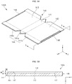
- FIGS. 3A to 3G are perspective views or cross-sectional views illustrating an example method for manufacturing example secondary batteries 100 and 200.
- FIG. 3A shows a can at an initial stage of manufacture
- FIG. 3B is a cross-sectional view taken along the line A-A of FIG. 3A .
- a substantially planar metal plate 140A having a substantially uniform thickness may be provided using a blanking process and/or a notching process.
- the metal plate 140A may include a substantially rectangular bottom portion 141 having long sides and short sides, long side portions 142 and 143 horizontally extending from the respective long sides of the bottom portion 141, short side portions 144 and 145 horizontally extending from the bottom portion 141 and the respective long side portions 142 and 143, and stepped parts (or steps) 146 located in each of the long side portions 142 and 143.
- one of the short side portions 144 may include a first short side portion 144a extending from the short side of the bottom portion 141 in a substantially triangular shape, a second short side portion 144b horizontally extending from the long side portion 142, and a third short side portion 144c horizontally extending from the other long side portion 143.
- the second short side portion 144b may include an inclined periphery (e.g., an inclined side) facing the first short side portion 144a
- the third short side portion 144c may also include an inclined periphery (e.g., an inclined side) facing the first short side portion 144a.
- the second and third short side portions 144b and 144c may be configured to match (align) with the first short side portion 144a when the can 140 is assembled.
- each of the long side portions 142 and 143 may be substantially equal to that of each of the long sides of the bottom portion 141.
- the width of the first short side portion 144a (in a z-axis direction) may be substantially equal to that of each of the short sides of the bottom portion 141.
- the overall width of the second and third short side portions 144b and 144c (measured in the z-axis direction after the can 140 is assembled) may be substantially equal to the width of each of the short sides of the bottom portion 141.
- each of the long side portions 142 and 143 may be substantially equal to that of each of the short side portions 144 and 145 (measured in a y-axis direction after the can 140 is assembled).
- dotted lines indicate bending lines in a subsequent process to be described later in more detail.
- the stepped parts 146 may be located along first ends (or edges) of each of the long side portions 142 and 143.
- the stepped parts 146 are located at the ends (or edges) of the long side portions 142 and 143 that are facing away from the bottom portion 141 in the metal plate 140A, and the stepped parts 146 may include grooves having a set or predetermined depth.
- the stepped parts 146 may be formed by a forging process using a press.
- the stepped parts 146 may be configured to have a set or predetermined depth in the z-axis direction (a thickness direction of the long side portions 142 and 143 when the can 140 is assembled) and be positioned a set or predetermined distance away from the bottom portion 141 in the y-axis direction in which the long side portions 142 and 143 are extended when the can 140 is assembled.
- the z-axis direction thickness direction of the long side portions 142 and 143 when the can 140 is assembled
- the y-axis direction which is crossing (e.g., perpendicular to) the first direction and in which the long side portions 142 and 143 are extended from the bottom portion 141 when the can 140 is assembled
- the first direction (z-axis) may correspond to a thickness direction of the can 140
- the second direction (y-axis) may correspond to a height direction of the can 140.
- the stepped parts 146 are where the cap assembly 150 is placed when the metal plate 140A is bent and welded to form the can 140 in a later process.
- the stepped parts 146 may be located in both of the long side portions 142 and 143 positioned at opposite sides of the bottom portion 141. However, for brevity, the following description will focus on only the stepped part 146 located in one long side portion 142.
- curved portions 147 are located between the long side portion 142 and each of the short side portions 144 and 145.
- the curved portions 147 are boundary regions where the long side portion 142 and the short side portions 144 and 145 meet, as indicated by dotted lines in FIG. 3A .
- the boundary regions are bent in curved shapes when bending is performed between the long side portion 142 and each of the short side portions 144 and 145. Therefore, as shown in FIG. 3B , the boundary regions between the long side portion 142 and the short side portions 144 and 145, which are bent portions, will be defined as curved portions 147.
- the stepped parts 146 are configured to extend along the long side portion 142 toward the curved portions 147 (e.g., from one curved portion 147 to the other curved portion 147).
- the stepped parts 146 may not be entirely provided in the short side portions 144 and 145 (e.g., the short side portions 144 and 145 may not include any portion of the stepped parts 146), which is for the purpose of securing a welding area and a welding thickness when the second short side portion 144b and the third short side portion 144c are welded in a later process.
- the stepped parts 146 were entirely located in the second and third short side portions 144b and 144c, the second and third short side portions 144b and 144c may have relatively small thicknesses, resulting in welding failures. Therefore, according to embodiments of the present invention, the stepped parts 146 are provided on the long side portion 142 and the curved portions 147, thereby securing welding reliability.
- the stepped part 146 is formed to have a uniform depth W1 in the first direction (z-axis) in the long side portion 142.
- the depth W1 of the stepped part 146 may be approximately (about) 20% of the thickness of the metal plate 140A in the y-axis direction (when the can 140 is assembled, the depth W1 is measured in the z-axis direction).
- the stepped part 146 in the curved portions 147 of the metal plate 140A, the stepped part 146 may have a depth W2 in the y-axis direction (when the can 140 is assembled, the depth W2 is measured in the z-axis direction) that may be gradually reduced toward the short side portions 144 and 145.
- the depth W1 of the stepped part 146 in the long side portion 142 may be larger than the depth W2 of the stepped part 146 in the curved portions 147 (W1>W2).
- the stepped part 146 is formed to have a set or predetermined height along the second direction (y-axis).
- the stepped part 146 is formed to have a uniform height D along the second direction (y-axis) in the long side portion 142 and the curved portions 147 when the can 140 is assembled (in the metal plate 140A, the height D of the stepped parts 146 is measured in the z-axis direction).
- the second direction (y-axis) height D of the stepped part 146 may be equal to the thickness of the cap plate 151 in the second direction, when the can 140 is assembled.
- the stepped part 146 may function to securely (suitably) place and/or fix the cap plate 151 to the can 140. In some embodiments, this configuration can be commonly applied to the stepped part 146 located at the other long side portion 143.
- the metal plate 140A may include aluminum (Al), iron (Fe), copper (Cu), titanium (Ti), nickel (Ni), magnesium (Mg), chrome (Cr), manganese (Mn), zinc (Zn) or one or more alloys of any of these elements.
- the metal plate 140A may include nickel (Ni) plated iron (Fe) and/or SUS (e.g., SUS 301, SUS 304, SUS 305, SUS 316L, and/or SUS 321).
- the metal plate 140A may have a thickness in the range from approximately (about) 0.1 mm to approximately (about) 10 mm, and a deviation in the thickness of the metal plate 140A in all areas may be in the range from approximately (about) 0.1% to approximately (about) 1%. Therefore, embodiments of the present invention may provide the can 140 that is relatively thin and has a small thickness deviation, compared to the related art can.
- the metal plate 140A may be preprocessed to facilitate a bending process and/or a welding process, which will be described below.
- the metal plate 140A may be subjected to annealing treatment performed in a predetermined gas atmosphere and a set or predetermined temperature range for a set or predetermined period of time.
- the annealing treatment may be performed in an atmosphere of inert gas, such as argon (Ar) and/or nitrogen (N2) at a temperature ranging from approximately (about) 300°C to approximately (about) 1000°C for approximately (about) 10 seconds to approximately (about) 60 minutes.
- the annealing treatment may increase the elongate of the metal plate 140A by approximately (about) 5% to approximately (about) 60%. Accordingly, the bending process of the metal plate 140A may be easily performed, and occurrence of a spring-back phenomenon can be reduced or minimized, particularly after the bending process.
- the metal plate 140A may have a substantially planar top surface and a substantially planar bottom surface.
- the top surface of the metal plate 140A may be subjected to insulation treatment.
- a thin insulation film may be located on the top surface of metal plate 140A by forming a thin oxide layer (e.g., an anodizing layer) through a metal oxidation process or coating or laminating an insulation resin (e.g., polyimide, polypropylene or polyethylene).
- the top surface of the metal plate 140A may correspond to the interior surface of the can 140, and the bottom surface of the metal plate 140A may correspond to the exterior surface of the can 140.
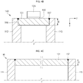
- FIG. 3C shows a can at a later stage of manufacture.
- the metal plate 140A may be bent in a set or predetermined shape.
- the metal plate 140A may be bent in a set or predetermined shape after it is fixed by a bending machine or a press mold.
- the long side portions 142 and 143 bent and extended from the respective long sides of the bottom portion 141 in a substantially perpendicular (normal) direction (with respect to the bottom portion 141), and the short side portions 144 and 145 bent and extended from the bottom portion 141 and the long side portions 142 and 143 in a substantially perpendicular (normal) direction (with respect to the bottom portion 141 and the long side portions 142 and 143), may be provided as the result of the bending process.
- the long side portions 142 and 143 may be bent approximately (about) 90 degrees from the long sides of the bottom portion 141 to then be extended
- the short side portions 144 and 145 may be bent approximately (about) 90 degrees from the short sides of the bottom portion 141 to then be extended and may be bent approximately (about) 90 degrees from the long side portions 142 and 143 to then be extended.
- first short side portion 144a, the second short side portion 144b and the third short side portion 144c may be positioned to face one another and their peripheries (outer edges) may be matched (aligned) with one another and/or may contact one another.
- a vertical angle between the upper periphery of the first short side portion 144a and the short side of the bottom portion 141 may be in the range from approximately (about) 40 degrees to approximately (about) 50 degrees, for example, 45 degrees.
- a vertical angle between the periphery of the first short side portion 144a facing the second short side portion 144b or the third short side portion 144c, and the periphery of the respective one of the second and third short side portions 144b and 144c facing the first short side portion 144a may be in the range from approximately (about) 80 degrees to approximately (about) 100 degrees, for example, 90 degrees.
- an angle defined between each of two upper peripheries of the first short side portion 144a and the short side of the bottom portion 141 may be in the range from approximately (about) 40 degrees to approximately (about) 50 degrees, for example, 45 degrees
- an angle defined between the periphery of the second short side portion 144b facing one periphery of the first short side portion 144a and the long side portion 142 may be in the range from approximately (about) 40 degrees to approximately (about) 50 degrees, for example, 45 degrees
- the periphery of the third short side portion 144c facing the other periphery of the first short side portion 144a and the long side portion 143 may be in the range from approximately (about) 40 degrees to approximately (about) 50 degrees, for example, 45 degrees.
- a vertex at which the bottom portion 141, the one long side portion 142, the first short side portion 144a and the second short side portion 144b meet, and a vertex at which the bottom portion 141, the long side portion 143 meet, the first short side portion 144a and the third short side portion 144c, may be bent in a substantially round shape.
- FIG. 3C shows an example in which the short side portion 144 (or 145) is bent from the bottom portion 141 and the long side portion 142 (or 143). That is, FIG. 3C shows an example in which the long side portion 142 has yet to be bent from the bottom portion 141.
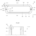
- FIG. 3D shows a can at a later stage of manufacture.
- FIG. 3E is a plan view of a can.
- FIG. 3F is a cross-sectional view taken along the line B-B of FIG. 3E
- FIG. 3G is a cross-sectional view taken along the line C-C of FIG. 3E .
- a welding process may be performed.
- the welding process may be performed by laser welding, ultrasonic welding and/or resistance welding.
- welding portions 148 are located in each of the short side portions 144 and 145.
- the welding portions 148 may be located in a boundary region between the first short side portion 144a and the second short side portion 144b, a boundary region between the first short side portion 144a and the third short side portion 144c and a boundary region between the second short side portion 144b and the third short side portion 144c.
- the welding portions 148 may include a butt joint structure, a lab joint structure, a cover joint structure and/or an edge joint structure. In one or more embodiments, the welding portions 148 may be in a substantially inverted Y-shaped (" ⁇ ") configuration. The welding portions 148 may be indicated by solid lines. Therefore, the first short side portion 144a may be perfectly (suitably) and securely fixed to the second and third short side portions 144b and 144c owing (due) to the welding portions 148, and the second and third short side portions 144b and 144c (or the second short side portions 144b and 144c) may perfectly (suitably) and securely fixed to each other.
- the second direction (y-axis) height D of the stepped part 146 is uniformly maintained in the long side portions 142 and 143 and the curved portions 147.
- the first direction (z-axis) depth W1 of the stepped part 146 in the long side portion 142 is larger than the first direction (z-axis) depth W2 of the stepped part 146 in the curved portions 147 (W1>W2).
- an interior curvature radius R2 of a top end of the can 140 having the stepped parts 146 is different from an interior curvature radius R1 of a bottom end of the can 140.
- the interior curvature radius R2 of the top end of the can 140 in the curved portions 147 is larger than the interior curvature radius R1 of the bottom end of the can 140.
- the corner of the cap plate 150 coupled to the stepped part 146 may be made to have a curved shape.
- the embodiments of the present invention provide the can 140 configured such that the first short side portion 144a is bent and extended from the bottom portion 141, the second and third short side portions 144b and 144c are bent and extended from the long side portions 142 and 143, and the first, second and third short side portions 144a, 144b and 144c are connected to one another through the welding portions 148 to construct one single short side portion 144, thereby increasing bending and welding workability, and improving sealing efficiency to prevent or reduce leakage of electrolyte.
- first short side portion 144a is bent and extended from the corresponding edge of the bottom portion 141, a welding process is not necessarily performed between the edge of the bottom portion 141 corresponding to (adjacent to) the first short side portion 144a and the first short side portion 144a.
- second and third short side portions 144b and 144c are bent and extended from the corresponding long side portions 142 and 143, respectively, a welding process is not necessarily needed to be performed between the edges of the long side portions 142 and 143 corresponding to (adjacent to) the second and third short side portions 144b and 144c and the second and third short side portions 144b and 144c.
- These configurations can be commonly applied to between the long side portions 142 and 143 and another short side portion 145.
- FIG. 4A is a plan view illustrating an example secondary battery
- FIG. 4B is a cross-sectional view taken along the line D-D of FIG. 4A
- FIG. 4C is a cross-sectional view taken along the line E-E of FIG. 4A .
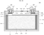
- the cap assembly 150 is mounted on the case 140 manufactured by the method shown in FIGS. 3A to 3G , and an interfacial surface between the can 140 and the cap plate 151 is then welded, thus completing the secondary battery 100.
- a welding portion 157 between the can 140 and the cap plate 151 may be connected to the welding portions 148 between the second short side portion 144b and the third short side portion 144c.
- the cap plate 151 may be shaped to correspond to the top opening of the can 140 having the stepped part 146. In other words, a thickness D of the cap plate 151 may be equal to the second direction (y-axis) thickness D of the stepped part 146 (see FIGS.
- the curvature radius R2 of the corner of the cap plate 151 may be equal to the interior curvature radius R2 of the top end of the can 140 in the curved portions 147, where the stepped parts 146 are located (see FIG. 4A ).
- the stepped parts 146 are provided in the long side portions 142 and 143 and the curved portions 147, rather than in the short side portions 144 and 145 of the can 140, thereby stably (suitably) supporting the cap plate 151 even if the length of the can 140 is increased.
- the stepped part 146 is provided in the long side portions 142 and 143 and the curved portions 147 by a forging process using a press in a state in which the can 140 is in form of the metal plate 140A which has yet to be bent, manufacturability can be improved reducing the processing cost.
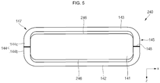
- FIG. 5 is a plan view illustrating a stepped part formed in a can of an example secondary battery.
- the can 240 may include a rectangular bottom portion 141 having long sides and short sides, long side portions 142 and 143 bent and extended from the respective long sides of the bottom portion 141 toward a cap assembly, short side portions 144 and 145 extended from the respective short sides of the bottom portion 141 and the long side portions 142 and 143, and a stepped part 246 located at an interior edge of a top end of the can 240.
- the stepped part 246 may be extended along the long side portions 142 toward the curved portions 147 and some portions of the short side portions 144.
- the stepped part 246 may not be located in the welding portions 148 of the short side portions 144, where the second short side portion 144b and the third short side portion 144c are welded, which is for the purpose of securing a welding area and a welding thickness of the welding portions 148 when the second short side portion 144b and the third short side portion 144c are welded.
- a first direction (x-axis) depth of the stepped part 246 may be uniformly maintained in the long side portion 142, while being gradually reduced in the curved portions 147 and the short side portion 144.
- a second direction (y-axis) height of the stepped part 246 may be uniformly maintained in all of the long side portion 142, the curved portions 147 and the short side portion 144.
Description
- The present disclosure relates to a secondary battery.
- A battery may be classified as a prismatic battery, a cylindrical battery, a pouch battery, etc., according to the shape of a case. A prismatic or cylindrical battery may be manufactured by inserting an electrode assembly having a positive electrode, a negative electrode and a separator into a metal can (or case) having the corresponding shape and sealing the electrode assembly, while a pouch type battery may be manufactured by enclosing an electrode assembly using an aluminum foil coated with an insulator.
- Traditional battery can (case or housing) manufacturing methods may include a deep drawing process, an impact process, and/or the like. For example, the
US 2012/0064389 A1 and theUS 2009/0311594 A1 disclose battery cans obtained by deep drawing the cans having supporting stepped portions. TheUS 9 123 916 B2 - However, the related art deep drawing process and the related art impact process are both limited in reducing a can thickness due to the respective manufacturing process characteristics and reveal a big deviation in the thickness of the can according to the area of the can. In addition, the related art deep drawing process and the related art impact process are problematic in that the manufacturing cost of the battery can is quite high.
- One or more aspects of embodiments of the present invention are directed toward a secondary battery, which can stably (suitably) support a cap plate even if the length of a can is increased.
- Embodiments of the present invention are also directed toward a secondary battery, which can improve manufacturability while reducing the processing cost by providing a stepped part in a can (or case) using a press forging process.
- According to the present invention, there is provided a secondary battery according to claim 1.
- Each of the long side portions of the case may include one or more of the stepped parts.
- The short side portions of the case may include one or more stepped parts.
- Each of the long side portions of the case may include one or more of the stepped parts, and each of the short side portions of the case may include one or more stepped parts.
- The stepped parts may have a uniform depth in the long side portions in a first direction, the first direction being a thickness direction of the case.
- Curved portions are located between the long side portions and the short side portions.
- The stepped parts extend along the long side portions toward the curved portions.
- The stepped parts may extend along entire lengths of the long side portions.
- The stepped parts have a depth in the curved portions in a first direction, the first direction being a thickness direction of the case, and the depth of the stepped parts in the curved portions is gradually reduced toward the short side portions.
- An interior curvature radius of a top end of the case having the stepped parts may be larger than that of a bottom end of the case.
- A curvature radius of a corner of the cap plate may be equal to the interior curvature radius of the top end of the case.
- The stepped parts may have a uniform height in a second direction in the long side portions and the curved portions, the second direction being a height direction of the case.
- The height of each of the stepped parts in the second direction may be equal to a thickness of the cap plate in the second direction.
- The stepped parts may extend from the curved portions to at least a portion of the short side portions.
- The stepped parts have a depth in the short side portions in the first direction, and the depth of the stepped parts in the short side portions may be gradually reduced.
- The cap plate may be coupled to the stepped parts.
- Each of the short side portions may be configured by combining a first short side portion bent and extended from the bottom portion and second and third short side portions extending from a respective one of the long side portions, and the short side portions may include welding portions which connect the first, second, and third short side portions to each other by welding.
- Each of the short side portions may be formed by connecting a first short side portion bent and extended from the bottom portion and second and third short side portions extending from a respective one of the long side portions.
- As described above, according to various embodiments of the present invention, a stepped part is located in each of long side portions to stably support a cap plate even if the length of a case is increased.
- In addition, according to various embodiments of the present invention, a stepped part is formed through a forging process using a press in a state in which a case is in form of a metal plate which has yet to be bent, thereby improving manufacturability while reducing the processing cost.
-
-
FIG. 1 is a perspective view illustrating an example secondary battery according to an embodiment of the present invention. -
FIGS. 2A and2B are cross-sectional views illustrating example secondary batteries. -
FIGS. 3A to 3G are perspective views or cross-sectional views illustrating an example method for manufacturing example secondary batteries. -
FIG. 4A is a plan view illustrating an example secondary battery. -
FIG. 4B is a cross-sectional view taken along the line D-D ofFIG. 4A . -
FIG. 4C is a cross-sectional view taken along the line E-E ofFIG. 4A . -
FIG. 5 is a plan view illustrating a stepped part formed in a case of an example secondary battery. - Hereinafter, example embodiments of the present invention will be described in more detail.
- In addition, in the accompanying drawings, sizes or thicknesses of various components may be exaggerated for brevity and clarity. Like numbers refer to like elements throughout. In addition, it will be understood that when an element A is referred to as being "connected to" an element B, the element A can be directly connected to the element B or one or more intervening elements C may be present and the element A and the element B may then be indirectly connected to each other.
- As used herein, the singular forms are intended to include the plural forms as well, unless the context clearly indicates otherwise. It will be further understood that the terms "comprise" or "include" and/or "comprising" or "including," when used in this specification, specify the presence of stated features, numbers, steps, operations, elements, and/or components, but do not preclude the presence or addition of one or more other features, numbers, steps, operations, elements, components, and/or groups thereof.
- Meanwhile, the term "welding portion" used throughout this specification can be referred to as a temporary welding portion and/or a welding portion in some cases, which is for representing the welding sequence and function but is not intended to limit the invention. In addition, the term "welding" as used herein mainly refers to laser welding, and examples of laser used for welding may include, but not limited to, CO2 laser, fiber laser, disk laser, semiconductor laser and/or YAG(Yttrium Aluminum Garnet) laser. In addition, the terms "second short side portion" and "third short side portion" can be collectively referred to as second short side portions, in some cases.
- Expressions such as "at least one of," "one of," and "selected from," when preceding a list of elements, modify the entire list of elements and do not modify the individual elements of the list. Further, the use of "may" when describing embodiments of the present invention refers to "one or more embodiments of the present invention."
-
FIG. 1 is a perspective view illustrating an example secondary battery according to an embodiment of the present invention. In the example shown inFIG. 1 , thesecondary battery 100 may include anelectrode assembly 110, afirst terminal 120, asecond terminal 130, a can (or case) 140 and acap assembly 150. - In one or more embodiments, the
can 140 may be provided by blanking and/or notching, bending and welding a metal plate and may have a substantially hexahedral shape having an opening through which theelectrode assembly 110 is inserted and placed and onto which thecap assembly 150 is mounted. In one or more embodiments, thecan 140 may include arectangular bottom portion 141 having long sides and short sides,long side portions bottom portion 141 to thecap assembly 150, andshort side portions bottom portion 141 and thelong side portions - In
FIG. 1 , thecan 140 and thecap assembly 150 assembled (coupled) to each other are illustrated. As such, the opening, which is a substantially open part of a region of thecan 140 corresponding to thecap assembly 150, is not illustrated inFIG. 1 . In one or more embodiments, the interior surface of thecan 140 may be subjected to insulation treatment such that thecan 140 is insulated from the electrode assembly, thefirst terminal 120, thesecond terminal 130 and thecap assembly 150. -
FIGS. 2A and2B are cross-sectional views illustrating examplesecondary batteries FIG. 2A , thesecondary battery 100 may include anelectrode assembly 110 having a winding axis extending in a horizontal direction (i.e., in a direction substantially parallel with a lengthwise direction of the cap assembly 150). In the example shown inFIG. 2B , thesecondary battery 200 may include anelectrode assembly 210 having a winding axis extending in a vertical direction (i.e., in a direction substantially perpendicular to the lengthwise direction of the cap assembly 150). In one or more embodiments, the electrode assembly may be a stacked electrode assembly, not a wound electrode assembly. - The
secondary battery 100 shown inFIG. 2A will now be described in more detail. Theelectrode assembly 110 may be formed by winding or stacking a stacked structure including afirst electrode plate 111, aseparator 113, and asecond electrode plate 112, which are thin plates or layers. In one or more embodiments, thefirst electrode plate 111 may operate as a negative electrode and thesecond electrode plate 112 may operate as a positive electrode, and vice versa. - In one or more embodiments, the
first electrode plate 111 may be formed by coating a first active material, such as graphite and/or carbon, on a first electrode collector made of a metal foil, such as copper, a copper alloy, nickel, and/or a nickel alloy, and may include a firstuncoated portion 111a that is not coated with the first active material. In one or more embodiments, thesecond electrode plate 112 may be formed by coating a second active material, such as a transition metal oxide, on a second electrode collector made of a metal foil, such as aluminum or an aluminum alloy, and may include a seconduncoated portion 112a that is not coated with the second electrode material. In one or more embodiments, theseparator 113, which is located between the first andsecond electrode plates second electrode plates separator 113 may include polyethylene, polypropylene, or a composite film of polyethylene and polypropylene. In some embodiments, theseparator 113 may be replaced by an inorganic solid electrolyte, such as a sulfide-based compound, an oxide-based compound, or a sulphate compound, not necessitating a liquid- or gel-phase electrolyte solution. Thefirst terminal 120 and thesecond terminal 130 electrically connected to thefirst electrode plate 111 and thesecond electrode plate 112, respectively, are located at opposite ends of theelectrode assembly 110. In one or more embodiments, theelectrode assembly 110 can be accommodated in thecan 140 with an electrolytic solution. In one or more embodiments, the electrolytic solution may include an organic solvent, such as ethylene carbonate (EC), propylene carbonate (PC), diethyl carbonate (DEC), ethyl methyl carbonate (EMC), and/or dimethyl carbonate (DMC), and a lithium salt, such as LiPF6and/or LiBF4. In one or more embodiments, if the inorganic solid electrolyte is used, the electrolytic solution may be omitted. - The
first terminal 120 may be made of a metal and may be electrically connected to thefirst electrode plate 111. In one or more embodiments, thefirst terminal 120 may include afirst collector plate 121, a firstterminal pillar 122 and a firstterminal plate 124. In one or more embodiments, thefirst collector plate 121 may be brought into contact with the firstuncoated portion 111a protruding to one end of theelectrode assembly 110. Thefirst collector plate 121 may be welded to the firstuncoated portion 111a. In one or more embodiments, thefirst collector plate 121 may be roughly in an inverted L-shaped ("┌" ) configuration and may have aterminal hole 121a located in its top portion. In one or more embodiments, the firstterminal pillar 122 may be inserted into theterminal hole 121a, followed by riveting and/or welding. In one or more embodiments, thefirst collector plate 121 may be made of copper or a copper alloy. In one or more embodiments, the firstterminal pillar 122 penetrates thecap plate 151 to be described later and is electrically connected to thefirst collector plate 121 under thecap plate 151. In one or more embodiments, the firstterminal pillar 122 is extended to an upper portion of thecap plate 151 and upwardly protruded by a set or predetermined length, and aflange 122a may be located below thecap plate 151 to prevent or protect the firstterminal pillar 122 from being dislodged from thecap plate 151. A portion of the firstterminal pillar 122 positioned below theflange 122a is fitted into the firstterminal hole 121a of thefirst collector plate 121, followed by riveting and/or welding. In one or more embodiments, the firstterminal pillar 122 may be electrically insulated from thecap plate 151. In one or more embodiments, boundary regions of the upwardly exposed portion of the firstterminal pillar 122 and the firstterminal plate 124 may be welded to each other. For example, laser beam may be supplied to the boundary regions of the upwardly exposed portion of the firstterminal pillar 122 and the firstterminal plate 124 to melt the boundary regions thereof, followed by cooling, thereby welding the boundary regions. The welded regions are designated byreference number 125 inFIG. 2A . Meanwhile, a bus bar made of aluminum or an aluminum alloy may be welded to the firstterminal plate 124. - The
second terminal 130 may also be made of a metal and may be electrically connected to thesecond electrode plate 112. In one or more embodiments, thesecond terminal 130 may include asecond collector plate 131, a secondterminal pillar 132 and a secondterminal plate 134. In one or more embodiments, thesecond collector plate 131 may be brought into contact with the seconduncoated portion 112a protruding to one end of theelectrode assembly 110. In one or more embodiments, thesecond collector plate 131 may be roughly in an inverted L-shaped ("┐") configuration and may have aterminal hole 131a located in its top portion. In one or more embodiments, the secondterminal pillar 132 may be inserted into theterminal hole 131a and then coupled thereto. In one or more embodiments, thesecond collector plate 131 may be made of, for example, but not limited to, aluminum or an aluminum alloy. In one or more embodiments, the secondterminal pillar 132 penetrates (e.g., goes through) thecap plate 151 to be described later and is electrically connected to thesecond collector plate 131 under thecap plate 151. In one or more embodiments, the secondterminal pillar 132 is extended to an upper portion of thecap plate 151 and upwardly protruded by a set or predetermined length, and aflange 132a may be located below thecap plate 151 to prevent or protect the secondterminal pillar 132 from being dislodged from thecap plate 151. A portion of the secondterminal pillar 132 positioned below theflange 132a is fitted into the secondterminal hole 131a of thesecond collector plate 131, followed by riveting and/or welding. Here, the secondterminal pillar 132 may be electrically insulated from thecap plate 151. In one or more embodiments, the secondterminal pillar 132 may be made of aluminum or an aluminum alloy. The secondterminal plate 134 has ahole 134a. In some embodiments, the secondterminal plate 134 is coupled to the secondterminal pillar 132. That is, the secondterminal pillar 132 is coupled to thehole 134a of the secondterminal plate 134. In some embodiments, the secondterminal pillar 132 and the secondterminal plate 134 may be riveted and/or welded to each other. In one or more embodiments, boundary regions of the upwardly exposed portion of the secondterminal pillar 132 and the secondterminal plate 134 may be welded to each other. For example, laser beam may be supplied to the boundary regions of the upwardly exposed portion of the secondterminal pillar 132 and the secondterminal plate 134 to melt the boundary regions, followed by cooling, thereby welding the boundary regions. The welded regions are designated byreference number 135 inFIG. 2A . Meanwhile, a bus bar made of aluminum or an aluminum alloy may be easily welded to the secondterminal plate 134. Here, the secondterminal plate 134 may be electrically connected to thecap plate 151. Thus, thecap plate 151 and thecan 140 may have the same polarity as the second terminal 130 (e.g., a positive polarity). - The
cap assembly 150 may be coupled to thecan 140. In one or more embodiments, thecap assembly 150 may include thecap plate 151, aseal gasket 152, aplug 153, asafety vent 154, anupper coupling member 155 and a lower insulatingmember 156. Thecap plate 151 may seal the opening of thecase 140, and may be made of the same material as thecase 140. In one or more embodiments, thecap plate 151 may be coupled to thecan 140 by laser welding. In the embodiments in which thecap plate 151 has the same polarity as thesecond terminal 130, thecap plate 151 and thecan 140 may have the same polarity. Theseal gasket 152 made of an insulating material may be located between each of the firstterminal pillar 122 and the secondterminal pillar 132 and thecap plate 151 at a bottom end of thecap plate 151 and may seal regions between each of the firstterminal pillar 122 and the secondterminal pillar 132 and thecap plate 151. Theseal gasket 152 may prevent or reduce external moisture from permeating into thesecondary battery 100 or prevent or reduce the electrolyte accommodated in thesecondary battery 100 from being effused outside. Theplug 153 may seal anelectrolyte injection hole 151a of thecap plate 151. Thesafety vent 154 may be installed in avent hole 151b of thecap plate 151 and may have anotch 154a configured to be openable at a preset (or set) pressure. Theupper coupling member 155 may be located between each of the firstterminal pillar 122 and the secondterminal pillar 132 and thecap plate 151 at a top end of thecap plate 151. In some embodiments, theupper coupling member 155 may closely contact thecap plate 151. In some embodiments, theupper coupling member 155 may also closely contact and theseal gasket 152. Theupper coupling member 155 may insulate the firstterminal pillar 122 and the secondterminal pillar 132 from thecap plate 151. In one or more embodiments, theupper coupling member 155 located in the secondterminal pillar 132 may electrically connect the secondterminal plate 134 and thecap plate 151 to each other. Accordingly, thesecond terminal 130 may have the same polarity as thecap plate 151 and thecan 140. The lower insulatingmember 156 may be located between each of thefirst collector plate 121 and thesecond collector plate 131 and thecap plate 151 and may prevent or reduce an unnecessary short circuit from being generated. That is, the lower insulatingmember 156 may prevent or reduce short circuits from being generated between thefirst collector plate 121 and thecap plate 151 and between thesecond collector plate 131 and thecap plate 151. - The
secondary battery 200 shown inFIG. 2B will now be described. Thesecondary battery 200 is different from thesecondary battery 100 in terms of the construction of theelectrode assembly 210 and the connection relationships between theelectrode assembly 210 and each of theterminals first electrode tab 211a may be positioned between theelectrode assembly 210 and a firstterminal pillar 122 of afirst terminal 120, and asecond electrode tab 212a may be positioned between theelectrode assembly 210 and a secondterminal pillar 132 of asecond terminal 130. Specifically, thefirst electrode tab 211a may be extended from a top end of theelectrode assembly 210 to a bottom end of the firstterminal pillar 122 of thefirst terminal 120 to then be electrically connected or welded to aplanar flange 122a provided in the firstterminal pillar 122. In some embodiments, thesecond electrode tab 212a may be extended from a top end of theelectrode assembly 210 to a bottom end of the secondterminal pillar 132 of thesecond terminal 130 to then be electrically connected or welded to aplanar flange 132a provided in the secondterminal pillar 132. Thefirst electrode tab 211a may be either a first uncoated portion of thefirst electrode plate 211 of theelectrode assembly 210, which is not coated with a firstactive material 211b, or a separate member connected to the first uncoated portion. Here, the first uncoated portion may be made of the same material as thefirst electrode plate 211, and a material for forming the separate member may be one selected from the group consisting of nickel, a nickel alloy, copper, a copper alloy, aluminum, an aluminum alloy, and equivalents thereof. In some embodiments, thesecond electrode tab 212a may be either a second uncoated portion of thesecond electrode plate 212 of theelectrode assembly 210, which is not coated with a second active material, or a separate member connected to the second uncoated portion. Here, the second uncoated portion may be made of the same material as thesecond electrode plate 212, and a material for forming the separate member may be one selected from the group consisting of aluminum, an aluminum alloy nickel, a nickel alloy, copper, a copper alloy, and equivalents thereof. - As described above, since a winding axis of the
electrode assembly 210 and terminal axes of theterminals electrode assembly 210 has excellent electrolyte impregnation capability when an electrolyte is injected, and internal gases are rapidly transferred to asafety vent 154 during overcharging to make thesafety vent 154 quickly operate. In addition, electrode tabs (uncoated portions or separate members) of theelectrode assembly 210 are directly electrically connected to theterminals secondary battery 100 while reducing the number of components of thesecondary battery 100. -
FIGS. 3A to 3G are perspective views or cross-sectional views illustrating an example method for manufacturing examplesecondary batteries FIG. 3A shows a can at an initial stage of manufacture, andFIG. 3B is a cross-sectional view taken along the line A-A ofFIG. 3A . - In the example shown in
FIG. 3A , a substantiallyplanar metal plate 140A having a substantially uniform thickness may be provided using a blanking process and/or a notching process. In one or more embodiments, themetal plate 140A may include a substantiallyrectangular bottom portion 141 having long sides and short sides,long side portions bottom portion 141,short side portions bottom portion 141 and the respectivelong side portions long side portions - In one or more embodiments, one of the
short side portions 144 may include a firstshort side portion 144a extending from the short side of thebottom portion 141 in a substantially triangular shape, a secondshort side portion 144b horizontally extending from thelong side portion 142, and a thirdshort side portion 144c horizontally extending from the otherlong side portion 143. Here, the secondshort side portion 144b may include an inclined periphery (e.g., an inclined side) facing the firstshort side portion 144a, and the thirdshort side portion 144c may also include an inclined periphery (e.g., an inclined side) facing the firstshort side portion 144a. In other words, the second and thirdshort side portions short side portion 144a when thecan 140 is assembled. - In some embodiments, the length of each of the
long side portions 142 and 143 (in an x-axis direction) may be substantially equal to that of each of the long sides of thebottom portion 141. The width of the firstshort side portion 144a (in a z-axis direction) may be substantially equal to that of each of the short sides of thebottom portion 141. The overall width of the second and thirdshort side portions can 140 is assembled) may be substantially equal to the width of each of the short sides of thebottom portion 141. In some embodiments, the height of each of thelong side portions short side portions 144 and 145 (measured in a y-axis direction after thecan 140 is assembled). InFIG. 3A , dotted lines indicate bending lines in a subsequent process to be described later in more detail. - The stepped
parts 146 may be located along first ends (or edges) of each of thelong side portions parts 146 are located at the ends (or edges) of thelong side portions bottom portion 141 in themetal plate 140A, and the steppedparts 146 may include grooves having a set or predetermined depth. In one or more embodiments, the steppedparts 146 may be formed by a forging process using a press. The steppedparts 146 may be configured to have a set or predetermined depth in the z-axis direction (a thickness direction of thelong side portions can 140 is assembled) and be positioned a set or predetermined distance away from thebottom portion 141 in the y-axis direction in which thelong side portions can 140 is assembled. Here, the z-axis direction (thickness direction of thelong side portions can 140 is assembled) is defined as a first direction, and the y-axis direction (which is crossing (e.g., perpendicular to) the first direction and in which thelong side portions bottom portion 141 when thecan 140 is assembled) is defined as a second direction. In one or more embodiments, the first direction (z-axis) may correspond to a thickness direction of thecan 140, and the second direction (y-axis) may correspond to a height direction of thecan 140. - In some embodiments, the stepped
parts 146 are where thecap assembly 150 is placed when themetal plate 140A is bent and welded to form thecan 140 in a later process. The steppedparts 146 may be located in both of thelong side portions bottom portion 141. However, for brevity, the following description will focus on only the steppedpart 146 located in onelong side portion 142. Referring toFIG. 3B ,curved portions 147 are located between thelong side portion 142 and each of theshort side portions curved portions 147 are boundary regions where thelong side portion 142 and theshort side portions FIG. 3A . In practice, the boundary regions are bent in curved shapes when bending is performed between thelong side portion 142 and each of theshort side portions FIG. 3B , the boundary regions between thelong side portion 142 and theshort side portions curved portions 147. The steppedparts 146 are configured to extend along thelong side portion 142 toward the curved portions 147 (e.g., from onecurved portion 147 to the other curved portion 147). However, the steppedparts 146 may not be entirely provided in theshort side portions 144 and 145 (e.g., theshort side portions short side portion 144b and the thirdshort side portion 144c are welded in a later process. For example, if the steppedparts 146 were entirely located in the second and thirdshort side portions short side portions parts 146 are provided on thelong side portion 142 and thecurved portions 147, thereby securing welding reliability. - The stepped
part 146 is formed to have a uniform depth W1 in the first direction (z-axis) in thelong side portion 142. For example, in thelong side portion 142, the depth W1 of the steppedpart 146 may be approximately (about) 20% of the thickness of themetal plate 140A in the y-axis direction (when thecan 140 is assembled, the depth W1 is measured in the z-axis direction). In some embodiments, in thecurved portions 147 of themetal plate 140A, the steppedpart 146 may have a depth W2 in the y-axis direction (when thecan 140 is assembled, the depth W2 is measured in the z-axis direction) that may be gradually reduced toward theshort side portions part 146 in thelong side portion 142 may be larger than the depth W2 of the steppedpart 146 in the curved portions 147 (W1>W2). In some embodiments, the steppedpart 146 is formed to have a set or predetermined height along the second direction (y-axis). For example, the steppedpart 146 is formed to have a uniform height D along the second direction (y-axis) in thelong side portion 142 and thecurved portions 147 when thecan 140 is assembled (in themetal plate 140A, the height D of the steppedparts 146 is measured in the z-axis direction). In some embodiments, the second direction (y-axis) height D of the steppedpart 146 may be equal to the thickness of thecap plate 151 in the second direction, when thecan 140 is assembled. The steppedpart 146 may function to securely (suitably) place and/or fix thecap plate 151 to thecan 140. In some embodiments, this configuration can be commonly applied to the steppedpart 146 located at the otherlong side portion 143. - In one or more embodiments, the
metal plate 140A may include aluminum (Al), iron (Fe), copper (Cu), titanium (Ti), nickel (Ni), magnesium (Mg), chrome (Cr), manganese (Mn), zinc (Zn) or one or more alloys of any of these elements. In one or more embodiments, themetal plate 140A may include nickel (Ni) plated iron (Fe) and/or SUS (e.g., SUS 301, SUS 304, SUS 305, SUS 316L, and/or SUS 321). - In one or more embodiments, the
metal plate 140A may have a thickness in the range from approximately (about) 0.1 mm to approximately (about) 10 mm, and a deviation in the thickness of themetal plate 140A in all areas may be in the range from approximately (about) 0.1% to approximately (about) 1%. Therefore, embodiments of the present invention may provide thecan 140 that is relatively thin and has a small thickness deviation, compared to the related art can. - In one or more embodiments, the
metal plate 140A may be preprocessed to facilitate a bending process and/or a welding process, which will be described below. In one or more embodiments, themetal plate 140A may be subjected to annealing treatment performed in a predetermined gas atmosphere and a set or predetermined temperature range for a set or predetermined period of time. In one or more embodiments, the annealing treatment may be performed in an atmosphere of inert gas, such as argon (Ar) and/or nitrogen (N2) at a temperature ranging from approximately (about) 300°C to approximately (about) 1000°C for approximately (about) 10 seconds to approximately (about) 60 minutes. The annealing treatment may increase the elongate of themetal plate 140A by approximately (about) 5% to approximately (about) 60%. Accordingly, the bending process of themetal plate 140A may be easily performed, and occurrence of a spring-back phenomenon can be reduced or minimized, particularly after the bending process. - In some embodiments, the
metal plate 140A may have a substantially planar top surface and a substantially planar bottom surface. The top surface of themetal plate 140A may be subjected to insulation treatment. In one or more embodiments, a thin insulation film may be located on the top surface ofmetal plate 140A by forming a thin oxide layer (e.g., an anodizing layer) through a metal oxidation process or coating or laminating an insulation resin (e.g., polyimide, polypropylene or polyethylene). In one or more embodiments, the top surface of themetal plate 140A may correspond to the interior surface of thecan 140, and the bottom surface of themetal plate 140A may correspond to the exterior surface of thecan 140. -
FIG. 3C shows a can at a later stage of manufacture. In the example shown inFIG. 3C , themetal plate 140A may be bent in a set or predetermined shape. In one or more embodiments, themetal plate 140A may be bent in a set or predetermined shape after it is fixed by a bending machine or a press mold. - In one or more embodiments, the
long side portions bottom portion 141 in a substantially perpendicular (normal) direction (with respect to the bottom portion 141), and theshort side portions bottom portion 141 and thelong side portions bottom portion 141 and thelong side portions 142 and 143), may be provided as the result of the bending process. For example, thelong side portions bottom portion 141 to then be extended, and theshort side portions bottom portion 141 to then be extended and may be bent approximately (about) 90 degrees from thelong side portions - Therefore, the first
short side portion 144a, the secondshort side portion 144b and the thirdshort side portion 144c may be positioned to face one another and their peripheries (outer edges) may be matched (aligned) with one another and/or may contact one another. Here, as shown inFIG. 3A , a vertical angle between the upper periphery of the firstshort side portion 144a and the short side of thebottom portion 141 may be in the range from approximately (about) 40 degrees to approximately (about) 50 degrees, for example, 45 degrees. In some embodiments, a vertical angle between the periphery of the firstshort side portion 144a facing the secondshort side portion 144b or the thirdshort side portion 144c, and the periphery of the respective one of the second and thirdshort side portions short side portion 144a may be in the range from approximately (about) 80 degrees to approximately (about) 100 degrees, for example, 90 degrees. - In one or more embodiments, an angle defined between each of two upper peripheries of the first
short side portion 144a and the short side of thebottom portion 141 may be in the range from approximately (about) 40 degrees to approximately (about) 50 degrees, for example, 45 degrees, an angle defined between the periphery of the secondshort side portion 144b facing one periphery of the firstshort side portion 144a and thelong side portion 142 may be in the range from approximately (about) 40 degrees to approximately (about) 50 degrees, for example, 45 degrees, and the periphery of the thirdshort side portion 144c facing the other periphery of the firstshort side portion 144a and thelong side portion 143 may be in the range from approximately (about) 40 degrees to approximately (about) 50 degrees, for example, 45 degrees. Accordingly, a vertex at which thebottom portion 141, the onelong side portion 142, the firstshort side portion 144a and the secondshort side portion 144b meet, and a vertex at which thebottom portion 141, thelong side portion 143 meet, the firstshort side portion 144a and the thirdshort side portion 144c, may be bent in a substantially round shape. - Meanwhile,
FIG. 3C shows an example in which the short side portion 144 (or 145) is bent from thebottom portion 141 and the long side portion 142 (or 143). That is,FIG. 3C shows an example in which thelong side portion 142 has yet to be bent from thebottom portion 141. -
FIG. 3D shows a can at a later stage of manufacture.FIG. 3E is a plan view of a can.FIG. 3F is a cross-sectional view taken along the line B-B ofFIG. 3E , andFIG. 3G is a cross-sectional view taken along the line C-C ofFIG. 3E . - In the example shown in
FIG. 3D , a welding process may be performed. In one or more embodiments, the welding process may be performed by laser welding, ultrasonic welding and/or resistance welding. In the present invention,welding portions 148 are located in each of theshort side portions welding portions 148 may be located in a boundary region between the firstshort side portion 144a and the secondshort side portion 144b, a boundary region between the firstshort side portion 144a and the thirdshort side portion 144c and a boundary region between the secondshort side portion 144b and the thirdshort side portion 144c. - In one or more embodiments, the
welding portions 148 may include a butt joint structure, a lab joint structure, a cover joint structure and/or an edge joint structure. In one or more embodiments, thewelding portions 148 may be in a substantially inverted Y-shaped ("λ") configuration. Thewelding portions 148 may be indicated by solid lines. Therefore, the firstshort side portion 144a may be perfectly (suitably) and securely fixed to the second and thirdshort side portions welding portions 148, and the second and thirdshort side portions short side portions - Referring to
FIGS. 3E, 3F and3G , the second direction (y-axis) height D of the steppedpart 146 is uniformly maintained in thelong side portions curved portions 147. However, the first direction (z-axis) depth W1 of the steppedpart 146 in thelong side portion 142 is larger than the first direction (z-axis) depth W2 of the steppedpart 146 in the curved portions 147 (W1>W2). Accordingly, as shown inFIG. 3E , in thecurved portions 147 of thecan 140, an interior curvature radius R2 of a top end of thecan 140 having the steppedparts 146 is different from an interior curvature radius R1 of a bottom end of thecan 140. In other words, after thecan 140 is assembled, because the steppedparts 146 are located in thelong side portions curved portions 147 at the top end of thecan 140, and the first direction (z-axis) depth W2 of the steppedparts 146 in thecurved portions 147 is gradually reduced toward theshort side portions can 140 in thecurved portions 147 is larger than the interior curvature radius R1 of the bottom end of thecan 140. As described above, if the first direction (z-axis) depth W2 of the steppedpart 146 in thecurved portions 147 is made to be gradually reduced toward theshort side portions cap plate 150 coupled to the steppedpart 146 may be made to have a curved shape. - The embodiments of the present invention provide the
can 140 configured such that the firstshort side portion 144a is bent and extended from thebottom portion 141, the second and thirdshort side portions long side portions short side portions welding portions 148 to construct one singleshort side portion 144, thereby increasing bending and welding workability, and improving sealing efficiency to prevent or reduce leakage of electrolyte. - Here, since the first
short side portion 144a is bent and extended from the corresponding edge of thebottom portion 141, a welding process is not necessarily performed between the edge of thebottom portion 141 corresponding to (adjacent to) the firstshort side portion 144a and the firstshort side portion 144a. In some embodiments, since the second and thirdshort side portions long side portions long side portions short side portions short side portions long side portions short side portion 145. -
FIG. 4A is a plan view illustrating an example secondary battery,FIG. 4B is a cross-sectional view taken along the line D-D ofFIG. 4A , andFIG. 4C is a cross-sectional view taken along the line E-E ofFIG. 4A . - As shown in
FIG. 4A , thecap assembly 150 is mounted on thecase 140 manufactured by the method shown inFIGS. 3A to 3G , and an interfacial surface between thecan 140 and thecap plate 151 is then welded, thus completing thesecondary battery 100. Awelding portion 157 between thecan 140 and thecap plate 151 may be connected to thewelding portions 148 between the secondshort side portion 144b and the thirdshort side portion 144c. Thecap plate 151 may be shaped to correspond to the top opening of thecan 140 having the steppedpart 146. In other words, a thickness D of thecap plate 151 may be equal to the second direction (y-axis) thickness D of the stepped part 146 (seeFIGS. 4B and 4C ), the curvature radius R2 of the corner of thecap plate 151 may be equal to the interior curvature radius R2 of the top end of thecan 140 in thecurved portions 147, where the steppedparts 146 are located (seeFIG. 4A ). - As described above, according to the present invention, the stepped
parts 146 are provided in thelong side portions curved portions 147, rather than in theshort side portions can 140, thereby stably (suitably) supporting thecap plate 151 even if the length of thecan 140 is increased. - According to various embodiments of the present invention, because the stepped
part 146 is provided in thelong side portions curved portions 147 by a forging process using a press in a state in which thecan 140 is in form of themetal plate 140A which has yet to be bent, manufacturability can be improved reducing the processing cost. -
FIG. 5 is a plan view illustrating a stepped part formed in a can of an example secondary battery. - As shown in
FIG. 5 , thecan 240 may include arectangular bottom portion 141 having long sides and short sides,long side portions bottom portion 141 toward a cap assembly,short side portions bottom portion 141 and thelong side portions part 246 located at an interior edge of a top end of thecan 240. The steppedpart 246 may be extended along thelong side portions 142 toward thecurved portions 147 and some portions of theshort side portions 144. However, the steppedpart 246 may not be located in thewelding portions 148 of theshort side portions 144, where the secondshort side portion 144b and the thirdshort side portion 144c are welded, which is for the purpose of securing a welding area and a welding thickness of thewelding portions 148 when the secondshort side portion 144b and the thirdshort side portion 144c are welded. A first direction (x-axis) depth of the steppedpart 246 may be uniformly maintained in thelong side portion 142, while being gradually reduced in thecurved portions 147 and theshort side portion 144. In some embodiments, a second direction (y-axis) height of the steppedpart 246 may be uniformly maintained in all of thelong side portion 142, thecurved portions 147 and theshort side portion 144.
Claims (13)
- A secondary battery comprising:an electrode assembly (110, 120);a case (140) configured to accommodate the electrode assembly (110, 120), the case (140) comprising a bottom portion (141), long side portions (142, 143), and short side portions (144, 145),a cap plate (151) coupled to the case (140),the long side portions (142, 143) comprising one or more stepped parts (146), located at the ends of said long side portions that are facing away from the bottom portion (141),wherein curved portions (147) are located between the long side portions (142, 143) and the short side portions (144, 145), wherein the stepped parts (146) extend along the long side portions (142, 143) toward the curved portions (147),wherein the stepped parts (146) each have a depth (W2) in the curved portions (147) in a first direction, the first direction being a thickness direction of the case (140),characterized in that,the short side portions (144, 145) are bent and welded and welding portions (148) are located in each of the short side portions (144,145), andwherein the depth (W2) of each of the stepped parts (146) in the curved portions (147) is gradually reduced toward the short side portions (144, 145).
- The secondary battery of claim 1, wherein each of the long side portions (142, 143) of the case (140) comprises one or more of the stepped parts (146).
- The secondary battery of one of the claims 1 to 2, wherein the short side portions (144, 145) of the case (140) comprise one or more stepped parts (246), and/or
each of the short side portions (144, 145) of the case (140) comprises one or more stepped parts (246). - The secondary battery of one of the claims 1 to 3, wherein the stepped parts (146) have a uniform depth (W1) in the long side portions (142, 143) in a first direction, the first direction being a thickness direction of the case (140).
- The secondary battery of one of the claims 1 to 4, wherein the stepped parts (146) extend along entire lengths of the long side portions (142, 143).
- The secondary battery of one of the claims 1 to 5, wherein an interior curvature radius (R2) of a top end of the case (140) having the stepped parts (146) is larger than an interior curvature radius (R1) of a bottom end of the case (140).
- The secondary battery of claim 6, wherein a curvature radius of a corner of the cap plate (151) is equal to the interior curvature radius (R2) of the top end of the case (140).
- The secondary battery of one of the claims 1 to 7, wherein the stepped parts (146) have a uniform height (D) in a second direction in the long side portions (142, 143) and the curved portions (147), the second direction being a height direction of the case (140).
- The secondary battery of claim 8, wherein the height (D) of each of the stepped parts (146) in the second direction is equal to a thickness of the cap plate (151) in the second direction.
- The secondary battery of one of the claims 1 to 9, wherein the stepped parts (246) extend from the curved portions (147) to portions of the short side portions (144, 145).
- The secondary battery of claim 10, wherein the stepped parts (246) have a depth in the short side portions (144, 145) in a first direction, the first direction being a thickness direction of the case (240), and
the depth of the stepped parts (246) in the short side portions (144, 145) is gradually reduced. - The secondary battery of one of the claims 1 to 11, wherein the cap plate (151) is coupled to the stepped parts (146).
- The secondary battery of one of the claims 1 to 12, wherein each of the short side portions (144, 145) is configured by combining a first short side portion (144a) bent and extended from the bottom portion (141) and second and third short side portions (144b, 144c) extending from a respective one of the long side portions (142, 143), and
the short side portions (144, 145) comprise welding portions (148) which connect the first, second, and third short side portions (144a, 144b, 144c) to each other by welding.
Priority Applications (1)
| Application Number | Priority Date | Filing Date | Title |
|---|---|---|---|
| PL20158768T PL3726602T3 (en) | 2019-04-18 | 2020-02-21 | Secondary battery |
Applications Claiming Priority (1)
| Application Number | Priority Date | Filing Date | Title |
|---|---|---|---|
| KR1020190045576A KR20200122630A (en) | 2019-04-18 | 2019-04-18 | Secondary battery |
Publications (2)
| Publication Number | Publication Date |
|---|---|
| EP3726602A1 EP3726602A1 (en) | 2020-10-21 |
| EP3726602B1 true EP3726602B1 (en) | 2021-11-10 |
Family
ID=69740113
Family Applications (1)
| Application Number | Title | Priority Date | Filing Date |
|---|---|---|---|
| EP20158768.0A Active EP3726602B1 (en) | 2019-04-18 | 2020-02-21 | Secondary battery |
Country Status (6)
| Country | Link |
|---|---|
| US (1) | US20200335739A1 (en) |
| EP (1) | EP3726602B1 (en) |
| KR (1) | KR20200122630A (en) |
| CN (1) | CN111834555B (en) |
| HU (1) | HUE057249T2 (en) |
| PL (1) | PL3726602T3 (en) |
Families Citing this family (1)
| Publication number | Priority date | Publication date | Assignee | Title |
|---|---|---|---|---|
| KR102607988B1 (en) * | 2023-09-07 | 2023-12-06 | (주)케이엔에스 | safety vent automatic welding apparatus of prismatic type secondary battery can |
Family Cites Families (11)
| Publication number | Priority date | Publication date | Assignee | Title |
|---|---|---|---|---|
| KR100709834B1 (en) * | 2005-04-26 | 2007-04-23 | 삼성에스디아이 주식회사 | Secondary battery |
| CN2859815Y (en) * | 2005-12-29 | 2007-01-17 | 比亚迪股份有限公司 | Battery cover sheet and electric battery |
| KR100983200B1 (en) * | 2008-06-12 | 2010-09-20 | 삼성에스디아이 주식회사 | Secondary Battery |
| KR101100990B1 (en) * | 2009-12-15 | 2011-12-29 | 삼성에스디아이 주식회사 | Secondary battery |
| KR101135498B1 (en) * | 2010-06-03 | 2012-04-13 | 삼성에스디아이 주식회사 | Rechargeable battery and can of the same |
| KR101182935B1 (en) * | 2010-09-13 | 2012-09-13 | 삼성에스디아이 주식회사 | Secondary Battery |
| JP6142466B2 (en) * | 2011-05-25 | 2017-06-07 | 株式会社Gsユアサ | Battery manufacturing method and battery |
| KR20130049535A (en) * | 2011-11-04 | 2013-05-14 | 삼성에스디아이 주식회사 | Rechargeable battery |
| WO2013175760A1 (en) * | 2012-05-22 | 2013-11-28 | 株式会社Gsユアサ | Electricity storage element |
| CN207124213U (en) * | 2017-05-31 | 2018-03-20 | 深圳市比亚迪锂电池有限公司 | A kind of battery container, battery cover board and battery |
| CN108987614B (en) * | 2017-05-31 | 2022-02-08 | 深圳市比亚迪锂电池有限公司 | Battery shell and battery |
-
2019
- 2019-04-18 KR KR1020190045576A patent/KR20200122630A/en active Search and Examination
-
2020
- 2020-01-22 US US16/749,238 patent/US20200335739A1/en not_active Abandoned
- 2020-02-21 HU HUE20158768A patent/HUE057249T2/en unknown
- 2020-02-21 PL PL20158768T patent/PL3726602T3/en unknown
- 2020-02-21 EP EP20158768.0A patent/EP3726602B1/en active Active
- 2020-03-13 CN CN202010174270.XA patent/CN111834555B/en active Active
Also Published As
| Publication number | Publication date |
|---|---|
| CN111834555A (en) | 2020-10-27 |
| CN111834555B (en) | 2022-12-30 |
| US20200335739A1 (en) | 2020-10-22 |
| KR20200122630A (en) | 2020-10-28 |
| HUE057249T2 (en) | 2022-04-28 |
| EP3726602A1 (en) | 2020-10-21 |
| PL3726602T3 (en) | 2022-02-28 |
Similar Documents
| Publication | Publication Date | Title |
|---|---|---|
| US10727469B2 (en) | Secondary battery | |
| US10840537B2 (en) | Method of manufacturing secondary battery and secondary battery manufactured by the method | |
| US20200251692A1 (en) | Secondary battery | |
| US20200091492A1 (en) | Secondary battery | |
| EP3726603A1 (en) | Secondary battery | |
| EP3726602B1 (en) | Secondary battery | |
| EP3745487B1 (en) | Secondary battery | |
| US11489223B2 (en) | Secondary battery | |
| EP4213278A1 (en) | Secondary battery | |
| KR20210056066A (en) | Secondary battery | |
| EP3761387A1 (en) | Secondary battery | |
| KR20210055543A (en) | Secondary battery | |
| US20220336894A1 (en) | Secondary battery | |
| KR20210050927A (en) | Secondary battery | |
| EP3595045B1 (en) | Secondary battery |
Legal Events
| Date | Code | Title | Description |
|---|---|---|---|
| PUAI | Public reference made under article 153(3) epc to a published international application that has entered the european phase |
Free format text: ORIGINAL CODE: 0009012 |
|
| STAA | Information on the status of an ep patent application or granted ep patent |
Free format text: STATUS: REQUEST FOR EXAMINATION WAS MADE |
|
| 17P | Request for examination filed |
Effective date: 20200221 |
|
| AK | Designated contracting states |
Kind code of ref document: A1 Designated state(s): AL AT BE BG CH CY CZ DE DK EE ES FI FR GB GR HR HU IE IS IT LI LT LU LV MC MK MT NL NO PL PT RO RS SE SI SK SM TR |
|
| AX | Request for extension of the european patent |
Extension state: BA ME |
|
| REG | Reference to a national code |
Ref country code: DE Ref legal event code: R079 Ref document number: 602020000936 Country of ref document: DE Free format text: PREVIOUS MAIN CLASS: H01M0002020000 Ipc: H01M0010040000 |
|
| GRAP | Despatch of communication of intention to grant a patent |
Free format text: ORIGINAL CODE: EPIDOSNIGR1 |
|
| STAA | Information on the status of an ep patent application or granted ep patent |
Free format text: STATUS: GRANT OF PATENT IS INTENDED |
|
| INTG | Intention to grant announced |
Effective date: 20210709 |
|
| RIC1 | Information provided on ipc code assigned before grant |
Ipc: H01M 10/04 20060101AFI20210628BHEP Ipc: H01M 10/052 20100101ALI20210628BHEP Ipc: H01M 10/058 20100101ALI20210628BHEP Ipc: H01M 50/103 20210101ALI20210628BHEP Ipc: H01M 50/116 20210101ALI20210628BHEP Ipc: H01M 50/15 20210101ALI20210628BHEP Ipc: H01M 50/169 20210101ALI20210628BHEP |
|
| GRAS | Grant fee paid |
Free format text: ORIGINAL CODE: EPIDOSNIGR3 |
|
| GRAA | (expected) grant |
Free format text: ORIGINAL CODE: 0009210 |
|
| STAA | Information on the status of an ep patent application or granted ep patent |
Free format text: STATUS: THE PATENT HAS BEEN GRANTED |
|
| AK | Designated contracting states |
Kind code of ref document: B1 Designated state(s): AL AT BE BG CH CY CZ DE DK EE ES FI FR GB GR HR HU IE IS IT LI LT LU LV MC MK MT NL NO PL PT RO RS SE SI SK SM TR |
|
| REG | Reference to a national code |
Ref country code: GB Ref legal event code: FG4D |
|
| REG | Reference to a national code |
Ref country code: AT Ref legal event code: REF Ref document number: 1446909 Country of ref document: AT Kind code of ref document: T Effective date: 20211115 Ref country code: CH Ref legal event code: EP |
|
| REG | Reference to a national code |
Ref country code: DE Ref legal event code: R096 Ref document number: 602020000936 Country of ref document: DE |
|
| REG | Reference to a national code |
Ref country code: IE Ref legal event code: FG4D |
|
| REG | Reference to a national code |
Ref country code: SE Ref legal event code: TRGR |
|
| REG | Reference to a national code |
Ref country code: LT Ref legal event code: MG9D |
|
| REG | Reference to a national code |
Ref country code: NL Ref legal event code: MP Effective date: 20211110 |
|
| REG | Reference to a national code |
Ref country code: AT Ref legal event code: MK05 Ref document number: 1446909 Country of ref document: AT Kind code of ref document: T Effective date: 20211110 |
|
| REG | Reference to a national code |
Ref country code: HU Ref legal event code: AG4A Ref document number: E057249 Country of ref document: HU |
|
| PG25 | Lapsed in a contracting state [announced via postgrant information from national office to epo] |
Ref country code: RS Free format text: LAPSE BECAUSE OF FAILURE TO SUBMIT A TRANSLATION OF THE DESCRIPTION OR TO PAY THE FEE WITHIN THE PRESCRIBED TIME-LIMIT Effective date: 20211110 Ref country code: LT Free format text: LAPSE BECAUSE OF FAILURE TO SUBMIT A TRANSLATION OF THE DESCRIPTION OR TO PAY THE FEE WITHIN THE PRESCRIBED TIME-LIMIT Effective date: 20211110 Ref country code: FI Free format text: LAPSE BECAUSE OF FAILURE TO SUBMIT A TRANSLATION OF THE DESCRIPTION OR TO PAY THE FEE WITHIN THE PRESCRIBED TIME-LIMIT Effective date: 20211110 Ref country code: BG Free format text: LAPSE BECAUSE OF FAILURE TO SUBMIT A TRANSLATION OF THE DESCRIPTION OR TO PAY THE FEE WITHIN THE PRESCRIBED TIME-LIMIT Effective date: 20220210 Ref country code: AT Free format text: LAPSE BECAUSE OF FAILURE TO SUBMIT A TRANSLATION OF THE DESCRIPTION OR TO PAY THE FEE WITHIN THE PRESCRIBED TIME-LIMIT Effective date: 20211110 |
|
| PG25 | Lapsed in a contracting state [announced via postgrant information from national office to epo] |
Ref country code: IS Free format text: LAPSE BECAUSE OF FAILURE TO SUBMIT A TRANSLATION OF THE DESCRIPTION OR TO PAY THE FEE WITHIN THE PRESCRIBED TIME-LIMIT Effective date: 20220310 Ref country code: PT Free format text: LAPSE BECAUSE OF FAILURE TO SUBMIT A TRANSLATION OF THE DESCRIPTION OR TO PAY THE FEE WITHIN THE PRESCRIBED TIME-LIMIT Effective date: 20220310 Ref country code: NO Free format text: LAPSE BECAUSE OF FAILURE TO SUBMIT A TRANSLATION OF THE DESCRIPTION OR TO PAY THE FEE WITHIN THE PRESCRIBED TIME-LIMIT Effective date: 20220210 Ref country code: NL Free format text: LAPSE BECAUSE OF FAILURE TO SUBMIT A TRANSLATION OF THE DESCRIPTION OR TO PAY THE FEE WITHIN THE PRESCRIBED TIME-LIMIT Effective date: 20211110 Ref country code: LV Free format text: LAPSE BECAUSE OF FAILURE TO SUBMIT A TRANSLATION OF THE DESCRIPTION OR TO PAY THE FEE WITHIN THE PRESCRIBED TIME-LIMIT Effective date: 20211110 Ref country code: HR Free format text: LAPSE BECAUSE OF FAILURE TO SUBMIT A TRANSLATION OF THE DESCRIPTION OR TO PAY THE FEE WITHIN THE PRESCRIBED TIME-LIMIT Effective date: 20211110 Ref country code: GR Free format text: LAPSE BECAUSE OF FAILURE TO SUBMIT A TRANSLATION OF THE DESCRIPTION OR TO PAY THE FEE WITHIN THE PRESCRIBED TIME-LIMIT Effective date: 20220211 |
|
| PG25 | Lapsed in a contracting state [announced via postgrant information from national office to epo] |
Ref country code: SM Free format text: LAPSE BECAUSE OF FAILURE TO SUBMIT A TRANSLATION OF THE DESCRIPTION OR TO PAY THE FEE WITHIN THE PRESCRIBED TIME-LIMIT Effective date: 20211110 Ref country code: SK Free format text: LAPSE BECAUSE OF FAILURE TO SUBMIT A TRANSLATION OF THE DESCRIPTION OR TO PAY THE FEE WITHIN THE PRESCRIBED TIME-LIMIT Effective date: 20211110 Ref country code: RO Free format text: LAPSE BECAUSE OF FAILURE TO SUBMIT A TRANSLATION OF THE DESCRIPTION OR TO PAY THE FEE WITHIN THE PRESCRIBED TIME-LIMIT Effective date: 20211110 Ref country code: ES Free format text: LAPSE BECAUSE OF FAILURE TO SUBMIT A TRANSLATION OF THE DESCRIPTION OR TO PAY THE FEE WITHIN THE PRESCRIBED TIME-LIMIT Effective date: 20211110 Ref country code: EE Free format text: LAPSE BECAUSE OF FAILURE TO SUBMIT A TRANSLATION OF THE DESCRIPTION OR TO PAY THE FEE WITHIN THE PRESCRIBED TIME-LIMIT Effective date: 20211110 Ref country code: DK Free format text: LAPSE BECAUSE OF FAILURE TO SUBMIT A TRANSLATION OF THE DESCRIPTION OR TO PAY THE FEE WITHIN THE PRESCRIBED TIME-LIMIT Effective date: 20211110 Ref country code: CZ Free format text: LAPSE BECAUSE OF FAILURE TO SUBMIT A TRANSLATION OF THE DESCRIPTION OR TO PAY THE FEE WITHIN THE PRESCRIBED TIME-LIMIT Effective date: 20211110 |
|
| REG | Reference to a national code |
Ref country code: DE Ref legal event code: R097 Ref document number: 602020000936 Country of ref document: DE |
|
| PLBE | No opposition filed within time limit |
Free format text: ORIGINAL CODE: 0009261 |
|
| STAA | Information on the status of an ep patent application or granted ep patent |
Free format text: STATUS: NO OPPOSITION FILED WITHIN TIME LIMIT |
|
| PG25 | Lapsed in a contracting state [announced via postgrant information from national office to epo] |
Ref country code: MC Free format text: LAPSE BECAUSE OF FAILURE TO SUBMIT A TRANSLATION OF THE DESCRIPTION OR TO PAY THE FEE WITHIN THE PRESCRIBED TIME-LIMIT Effective date: 20211110 |
|
| 26N | No opposition filed |
Effective date: 20220811 |
|
| REG | Reference to a national code |
Ref country code: BE Ref legal event code: MM Effective date: 20220228 |
|
| PG25 | Lapsed in a contracting state [announced via postgrant information from national office to epo] |
Ref country code: LU Free format text: LAPSE BECAUSE OF NON-PAYMENT OF DUE FEES Effective date: 20220221 Ref country code: AL Free format text: LAPSE BECAUSE OF FAILURE TO SUBMIT A TRANSLATION OF THE DESCRIPTION OR TO PAY THE FEE WITHIN THE PRESCRIBED TIME-LIMIT Effective date: 20211110 |
|
| PG25 | Lapsed in a contracting state [announced via postgrant information from national office to epo] |
Ref country code: SI Free format text: LAPSE BECAUSE OF FAILURE TO SUBMIT A TRANSLATION OF THE DESCRIPTION OR TO PAY THE FEE WITHIN THE PRESCRIBED TIME-LIMIT Effective date: 20211110 |
|
| PG25 | Lapsed in a contracting state [announced via postgrant information from national office to epo] |
Ref country code: IE Free format text: LAPSE BECAUSE OF NON-PAYMENT OF DUE FEES Effective date: 20220221 |
|
| PG25 | Lapsed in a contracting state [announced via postgrant information from national office to epo] |
Ref country code: BE Free format text: LAPSE BECAUSE OF NON-PAYMENT OF DUE FEES Effective date: 20220228 |
|
| PGFP | Annual fee paid to national office [announced via postgrant information from national office to epo] |
Ref country code: FR Payment date: 20230208 Year of fee payment: 4 |
|
| PG25 | Lapsed in a contracting state [announced via postgrant information from national office to epo] |
Ref country code: IT Free format text: LAPSE BECAUSE OF FAILURE TO SUBMIT A TRANSLATION OF THE DESCRIPTION OR TO PAY THE FEE WITHIN THE PRESCRIBED TIME-LIMIT Effective date: 20211110 |
|
| PGFP | Annual fee paid to national office [announced via postgrant information from national office to epo] |
Ref country code: SE Payment date: 20230126 Year of fee payment: 4 Ref country code: PL Payment date: 20230126 Year of fee payment: 4 |
|
| P01 | Opt-out of the competence of the unified patent court (upc) registered |
Effective date: 20230528 |
|
| REG | Reference to a national code |
Ref country code: CH Ref legal event code: PL |
|
| PG25 | Lapsed in a contracting state [announced via postgrant information from national office to epo] |
Ref country code: LI Free format text: LAPSE BECAUSE OF NON-PAYMENT OF DUE FEES Effective date: 20230228 Ref country code: CH Free format text: LAPSE BECAUSE OF NON-PAYMENT OF DUE FEES Effective date: 20230228 |
|
| PG25 | Lapsed in a contracting state [announced via postgrant information from national office to epo] |
Ref country code: MK Free format text: LAPSE BECAUSE OF FAILURE TO SUBMIT A TRANSLATION OF THE DESCRIPTION OR TO PAY THE FEE WITHIN THE PRESCRIBED TIME-LIMIT Effective date: 20211110 Ref country code: CY Free format text: LAPSE BECAUSE OF FAILURE TO SUBMIT A TRANSLATION OF THE DESCRIPTION OR TO PAY THE FEE WITHIN THE PRESCRIBED TIME-LIMIT Effective date: 20211110 |
|
| PGFP | Annual fee paid to national office [announced via postgrant information from national office to epo] |
Ref country code: HU Payment date: 20240220 Year of fee payment: 5 Ref country code: DE Payment date: 20240130 Year of fee payment: 5 Ref country code: GB Payment date: 20240201 Year of fee payment: 5 Ref country code: GB Payment date: 20240201 Year of fee payment: 4 Ref country code: GB Payment date: 20240201 Year of fee payment: 3 |