EP3690962A1 - Assembly, device and method for thermal treatment of a multilayer body - Google Patents
Assembly, device and method for thermal treatment of a multilayer body Download PDFInfo
- Publication number
- EP3690962A1 EP3690962A1 EP19154936.9A EP19154936A EP3690962A1 EP 3690962 A1 EP3690962 A1 EP 3690962A1 EP 19154936 A EP19154936 A EP 19154936A EP 3690962 A1 EP3690962 A1 EP 3690962A1
- Authority
- EP
- European Patent Office
- Prior art keywords
- multilayer body
- surface element
- arrangement
- energy source
- heat treatment
- Prior art date
- Legal status (The legal status is an assumption and is not a legal conclusion. Google has not performed a legal analysis and makes no representation as to the accuracy of the status listed.)
- Pending
Links
- 238000000034 method Methods 0.000 title claims description 92
- 238000007669 thermal treatment Methods 0.000 title description 2
- 238000010438 heat treatment Methods 0.000 claims abstract description 123
- 230000005855 radiation Effects 0.000 claims abstract description 45
- 230000008569 process Effects 0.000 claims description 82
- OKTJSMMVPCPJKN-UHFFFAOYSA-N Carbon Chemical compound [C] OKTJSMMVPCPJKN-UHFFFAOYSA-N 0.000 claims description 33
- 230000007797 corrosion Effects 0.000 claims description 23
- 238000005260 corrosion Methods 0.000 claims description 23
- 229910052751 metal Inorganic materials 0.000 claims description 22
- 239000002184 metal Substances 0.000 claims description 22
- 229910052799 carbon Inorganic materials 0.000 claims description 19
- 239000002131 composite material Substances 0.000 claims description 16
- 229910002804 graphite Inorganic materials 0.000 claims description 15
- 239000010439 graphite Substances 0.000 claims description 15
- 239000000853 adhesive Substances 0.000 claims description 12
- 230000001070 adhesive effect Effects 0.000 claims description 12
- 239000000919 ceramic Substances 0.000 claims description 12
- 239000002241 glass-ceramic Substances 0.000 claims description 12
- 239000011521 glass Substances 0.000 claims description 9
- VYPSYNLAJGMNEJ-UHFFFAOYSA-N Silicium dioxide Chemical compound O=[Si]=O VYPSYNLAJGMNEJ-UHFFFAOYSA-N 0.000 claims description 6
- 229920000049 Carbon (fiber) Polymers 0.000 claims description 5
- 239000005388 borosilicate glass Substances 0.000 claims description 5
- 239000004917 carbon fiber Substances 0.000 claims description 5
- VNWKTOKETHGBQD-UHFFFAOYSA-N methane Chemical compound C VNWKTOKETHGBQD-UHFFFAOYSA-N 0.000 claims description 5
- 239000005354 aluminosilicate glass Substances 0.000 claims description 4
- 239000010410 layer Substances 0.000 claims 2
- 239000010408 film Substances 0.000 description 35
- 239000011669 selenium Substances 0.000 description 30
- 239000002243 precursor Substances 0.000 description 28
- 239000000758 substrate Substances 0.000 description 28
- 229910052711 selenium Inorganic materials 0.000 description 25
- 229910052717 sulfur Inorganic materials 0.000 description 25
- 229910052798 chalcogen Inorganic materials 0.000 description 21
- 150000001787 chalcogens Chemical class 0.000 description 21
- 239000004065 semiconductor Substances 0.000 description 20
- BUGBHKTXTAQXES-UHFFFAOYSA-N Selenium Chemical compound [Se] BUGBHKTXTAQXES-UHFFFAOYSA-N 0.000 description 18
- 239000011888 foil Substances 0.000 description 17
- NINIDFKCEFEMDL-UHFFFAOYSA-N Sulfur Chemical compound [S] NINIDFKCEFEMDL-UHFFFAOYSA-N 0.000 description 16
- 239000011593 sulfur Substances 0.000 description 16
- 229910052733 gallium Inorganic materials 0.000 description 15
- 239000000463 material Substances 0.000 description 15
- 239000010409 thin film Substances 0.000 description 14
- 150000001875 compounds Chemical class 0.000 description 12
- 239000010949 copper Substances 0.000 description 12
- 229910052738 indium Inorganic materials 0.000 description 12
- 238000004519 manufacturing process Methods 0.000 description 12
- 239000006096 absorbing agent Substances 0.000 description 10
- 238000010521 absorption reaction Methods 0.000 description 8
- 238000001816 cooling Methods 0.000 description 8
- 238000006243 chemical reaction Methods 0.000 description 7
- GYHNNYVSQQEPJS-UHFFFAOYSA-N Gallium Chemical compound [Ga] GYHNNYVSQQEPJS-UHFFFAOYSA-N 0.000 description 6
- HVMJUDPAXRRVQO-UHFFFAOYSA-N copper indium Chemical compound [Cu].[In] HVMJUDPAXRRVQO-UHFFFAOYSA-N 0.000 description 6
- 238000005452 bending Methods 0.000 description 5
- 239000011248 coating agent Substances 0.000 description 5
- 238000000576 coating method Methods 0.000 description 5
- 238000010276 construction Methods 0.000 description 5
- 239000007789 gas Substances 0.000 description 5
- BWGNESOTFCXPMA-UHFFFAOYSA-N Dihydrogen disulfide Chemical compound SS BWGNESOTFCXPMA-UHFFFAOYSA-N 0.000 description 4
- ZOKXTWBITQBERF-UHFFFAOYSA-N Molybdenum Chemical compound [Mo] ZOKXTWBITQBERF-UHFFFAOYSA-N 0.000 description 4
- 238000013461 design Methods 0.000 description 4
- 239000011733 molybdenum Substances 0.000 description 4
- 229910018072 Al 2 O 3 Inorganic materials 0.000 description 3
- RYGMFSIKBFXOCR-UHFFFAOYSA-N Copper Chemical compound [Cu] RYGMFSIKBFXOCR-UHFFFAOYSA-N 0.000 description 3
- GPBUGPUPKAGMDK-UHFFFAOYSA-N azanylidynemolybdenum Chemical compound [Mo]#N GPBUGPUPKAGMDK-UHFFFAOYSA-N 0.000 description 3
- 229910052802 copper Inorganic materials 0.000 description 3
- 238000005265 energy consumption Methods 0.000 description 3
- APFVFJFRJDLVQX-UHFFFAOYSA-N indium atom Chemical compound [In] APFVFJFRJDLVQX-UHFFFAOYSA-N 0.000 description 3
- 230000035699 permeability Effects 0.000 description 3
- 238000002310 reflectometry Methods 0.000 description 3
- 238000007789 sealing Methods 0.000 description 3
- 230000005654 stationary process Effects 0.000 description 3
- MARUHZGHZWCEQU-UHFFFAOYSA-N 5-phenyl-2h-tetrazole Chemical compound C1=CC=CC=C1C1=NNN=N1 MARUHZGHZWCEQU-UHFFFAOYSA-N 0.000 description 2
- 229910001182 Mo alloy Inorganic materials 0.000 description 2
- BKQMNPVDJIHLPD-UHFFFAOYSA-N OS(=O)(=O)[Se]S(O)(=O)=O Chemical compound OS(=O)(=O)[Se]S(O)(=O)=O BKQMNPVDJIHLPD-UHFFFAOYSA-N 0.000 description 2
- QEWCDOSBINPOPV-UHFFFAOYSA-N S(=O)(=O)(O)[Se]S(=O)(=O)O.[Sn].[Zn].[Cu] Chemical compound S(=O)(=O)(O)[Se]S(=O)(=O)O.[Sn].[Zn].[Cu] QEWCDOSBINPOPV-UHFFFAOYSA-N 0.000 description 2
- ATJFFYVFTNAWJD-UHFFFAOYSA-N Tin Chemical compound [Sn] ATJFFYVFTNAWJD-UHFFFAOYSA-N 0.000 description 2
- 229910001080 W alloy Inorganic materials 0.000 description 2
- XLOMVQKBTHCTTD-UHFFFAOYSA-N Zinc monoxide Chemical compound [Zn]=O XLOMVQKBTHCTTD-UHFFFAOYSA-N 0.000 description 2
- 230000005540 biological transmission Effects 0.000 description 2
- 230000015572 biosynthetic process Effects 0.000 description 2
- 239000011203 carbon fibre reinforced carbon Substances 0.000 description 2
- 239000003518 caustics Substances 0.000 description 2
- 229910052951 chalcopyrite Inorganic materials 0.000 description 2
- -1 chalcopyrite compound Chemical class 0.000 description 2
- 238000009833 condensation Methods 0.000 description 2
- 230000005494 condensation Effects 0.000 description 2
- 239000013078 crystal Substances 0.000 description 2
- ZZEMEJKDTZOXOI-UHFFFAOYSA-N digallium;selenium(2-) Chemical compound [Ga+3].[Ga+3].[Se-2].[Se-2].[Se-2] ZZEMEJKDTZOXOI-UHFFFAOYSA-N 0.000 description 2
- 238000009826 distribution Methods 0.000 description 2
- 229910052736 halogen Inorganic materials 0.000 description 2
- 150000002367 halogens Chemical class 0.000 description 2
- 239000003112 inhibitor Substances 0.000 description 2
- 239000012212 insulator Substances 0.000 description 2
- 229910001092 metal group alloy Inorganic materials 0.000 description 2
- 229910052750 molybdenum Inorganic materials 0.000 description 2
- 230000000737 periodic effect Effects 0.000 description 2
- 239000004033 plastic Substances 0.000 description 2
- 230000009467 reduction Effects 0.000 description 2
- 238000007788 roughening Methods 0.000 description 2
- 125000006850 spacer group Chemical group 0.000 description 2
- 238000004544 sputter deposition Methods 0.000 description 2
- 238000005496 tempering Methods 0.000 description 2
- 238000002207 thermal evaporation Methods 0.000 description 2
- 229910052718 tin Inorganic materials 0.000 description 2
- 238000012546 transfer Methods 0.000 description 2
- JBRZTFJDHDCESZ-UHFFFAOYSA-N AsGa Chemical compound [As]#[Ga] JBRZTFJDHDCESZ-UHFFFAOYSA-N 0.000 description 1
- HCHKCACWOHOZIP-UHFFFAOYSA-N Zinc Chemical compound [Zn] HCHKCACWOHOZIP-UHFFFAOYSA-N 0.000 description 1
- KTSFMFGEAAANTF-UHFFFAOYSA-N [Cu].[Se].[Se].[In] Chemical compound [Cu].[Se].[Se].[In] KTSFMFGEAAANTF-UHFFFAOYSA-N 0.000 description 1
- YKTSYUJCYHOUJP-UHFFFAOYSA-N [O--].[Al+3].[Al+3].[O-][Si]([O-])([O-])[O-] Chemical compound [O--].[Al+3].[Al+3].[O-][Si]([O-])([O-])[O-] YKTSYUJCYHOUJP-UHFFFAOYSA-N 0.000 description 1
- 238000007792 addition Methods 0.000 description 1
- 230000008859 change Effects 0.000 description 1
- 239000000470 constituent Substances 0.000 description 1
- 238000004132 cross linking Methods 0.000 description 1
- 230000006378 damage Effects 0.000 description 1
- 230000003247 decreasing effect Effects 0.000 description 1
- 230000006735 deficit Effects 0.000 description 1
- 230000003111 delayed effect Effects 0.000 description 1
- 238000005137 deposition process Methods 0.000 description 1
- 238000011161 development Methods 0.000 description 1
- XIMIGUBYDJDCKI-UHFFFAOYSA-N diselenium Chemical compound [Se]=[Se] XIMIGUBYDJDCKI-UHFFFAOYSA-N 0.000 description 1
- 230000000694 effects Effects 0.000 description 1
- 238000005516 engineering process Methods 0.000 description 1
- 238000011010 flushing procedure Methods 0.000 description 1
- 239000003365 glass fiber Substances 0.000 description 1
- 230000001771 impaired effect Effects 0.000 description 1
- 238000002844 melting Methods 0.000 description 1
- 230000008018 melting Effects 0.000 description 1
- 229910044991 metal oxide Inorganic materials 0.000 description 1
- 150000004706 metal oxides Chemical class 0.000 description 1
- 150000002739 metals Chemical class 0.000 description 1
- 239000000203 mixture Substances 0.000 description 1
- 238000005457 optimization Methods 0.000 description 1
- 230000000704 physical effect Effects 0.000 description 1
- 229910021420 polycrystalline silicon Inorganic materials 0.000 description 1
- 229920000642 polymer Polymers 0.000 description 1
- 238000012545 processing Methods 0.000 description 1
- 238000005086 pumping Methods 0.000 description 1
- 239000010453 quartz Substances 0.000 description 1
- 230000006798 recombination Effects 0.000 description 1
- 238000005215 recombination Methods 0.000 description 1
- 230000001105 regulatory effect Effects 0.000 description 1
- 239000005368 silicate glass Substances 0.000 description 1
- 239000007787 solid Substances 0.000 description 1
- 230000006641 stabilisation Effects 0.000 description 1
- 238000011105 stabilization Methods 0.000 description 1
- 238000005987 sulfurization reaction Methods 0.000 description 1
- 230000003746 surface roughness Effects 0.000 description 1
- 229920001169 thermoplastic Polymers 0.000 description 1
- 239000004416 thermosoftening plastic Substances 0.000 description 1
- KUAZQDVKQLNFPE-UHFFFAOYSA-N thiram Chemical compound CN(C)C(=S)SSC(=S)N(C)C KUAZQDVKQLNFPE-UHFFFAOYSA-N 0.000 description 1
- 239000011135 tin Substances 0.000 description 1
- 230000009466 transformation Effects 0.000 description 1
- 239000012780 transparent material Substances 0.000 description 1
- 229910052725 zinc Inorganic materials 0.000 description 1
- 239000011701 zinc Substances 0.000 description 1
- 239000011787 zinc oxide Substances 0.000 description 1
Images


Classifications
-
- H—ELECTRICITY
- H01—ELECTRIC ELEMENTS
- H01L—SEMICONDUCTOR DEVICES NOT COVERED BY CLASS H10
- H01L31/00—Semiconductor devices sensitive to infrared radiation, light, electromagnetic radiation of shorter wavelength or corpuscular radiation and specially adapted either for the conversion of the energy of such radiation into electrical energy or for the control of electrical energy by such radiation; Processes or apparatus specially adapted for the manufacture or treatment thereof or of parts thereof; Details thereof
- H01L31/18—Processes or apparatus specially adapted for the manufacture or treatment of these devices or of parts thereof
- H01L31/186—Particular post-treatment for the devices, e.g. annealing, impurity gettering, short-circuit elimination, recrystallisation
- H01L31/1864—Annealing
-
- H—ELECTRICITY
- H01—ELECTRIC ELEMENTS
- H01L—SEMICONDUCTOR DEVICES NOT COVERED BY CLASS H10
- H01L21/00—Processes or apparatus adapted for the manufacture or treatment of semiconductor or solid state devices or of parts thereof
- H01L21/67—Apparatus specially adapted for handling semiconductor or electric solid state devices during manufacture or treatment thereof; Apparatus specially adapted for handling wafers during manufacture or treatment of semiconductor or electric solid state devices or components ; Apparatus not specifically provided for elsewhere
- H01L21/67005—Apparatus not specifically provided for elsewhere
- H01L21/67011—Apparatus for manufacture or treatment
- H01L21/67098—Apparatus for thermal treatment
- H01L21/67115—Apparatus for thermal treatment mainly by radiation
-
- Y—GENERAL TAGGING OF NEW TECHNOLOGICAL DEVELOPMENTS; GENERAL TAGGING OF CROSS-SECTIONAL TECHNOLOGIES SPANNING OVER SEVERAL SECTIONS OF THE IPC; TECHNICAL SUBJECTS COVERED BY FORMER USPC CROSS-REFERENCE ART COLLECTIONS [XRACs] AND DIGESTS
- Y02—TECHNOLOGIES OR APPLICATIONS FOR MITIGATION OR ADAPTATION AGAINST CLIMATE CHANGE
- Y02E—REDUCTION OF GREENHOUSE GAS [GHG] EMISSIONS, RELATED TO ENERGY GENERATION, TRANSMISSION OR DISTRIBUTION
- Y02E10/00—Energy generation through renewable energy sources
- Y02E10/50—Photovoltaic [PV] energy
-
- Y—GENERAL TAGGING OF NEW TECHNOLOGICAL DEVELOPMENTS; GENERAL TAGGING OF CROSS-SECTIONAL TECHNOLOGIES SPANNING OVER SEVERAL SECTIONS OF THE IPC; TECHNICAL SUBJECTS COVERED BY FORMER USPC CROSS-REFERENCE ART COLLECTIONS [XRACs] AND DIGESTS
- Y02—TECHNOLOGIES OR APPLICATIONS FOR MITIGATION OR ADAPTATION AGAINST CLIMATE CHANGE
- Y02P—CLIMATE CHANGE MITIGATION TECHNOLOGIES IN THE PRODUCTION OR PROCESSING OF GOODS
- Y02P70/00—Climate change mitigation technologies in the production process for final industrial or consumer products
- Y02P70/50—Manufacturing or production processes characterised by the final manufactured product
Definitions
- the multilayer body is heated essentially indirectly by the heated surface element by means of heat radiation and heat conduction.
- the surface element preferably has a low reflectivity and a high emissivity, so that the radiation emitted by the radiation field is largely absorbed.
- the cross section of the linear support elements is preferably round (circular or disk-shaped) or rectangular.
- the narrower surface lies parallel to the surface element (first surface).
- a rectangular cross-section with the narrower side parallel to the surface element ensures high rigidity with reduced shading.
- the cross-section of the linear support elements can be circular (round wire or round rod), ring-shaped (tube), T-shaped (T-beam) or double-T-shaped (double-T beam).
- the device for heat treating a multilayer body comprises a device for forming a (reduced) process space for a multilayer body.
- the process space is reduced in relation to the chamber volume of a chamber (heating or cooling chamber) in which the device for forming a reduced process space is located.
- the device for forming a process space comprises a bottom-side section, hereinafter referred to as "bottom”, a lid-side section, hereinafter referred to as "lid”, and at least one frame, which together form a gas-tight process space for receiving the multilayer body, at least during the heat treatment .
- the frame connects the bottom and the lid and also serves as a spacer for the lid and bottom.
- the frame is made of graphite or a composite such as carbon fiber reinforced carbon.
- the frame can be firmly connected to the cover and is then referred to as the "cover frame”. In this case, the frame is not firmly attached to the floor.
- the frame can be firmly connected to the floor and is then referred to as the "floor frame”. In this case, the frame is not firmly attached to the lid.
- the device for forming a process space can comprise two frames, a first frame being fixedly connected to the lid (and not firmly connected to the floor) and referred to as "lid frame”, and a second frame being fixedly connected to the floor (and is not firmly attached to the lid) and is referred to as "floor frame”. Bottom and cover frames are not firmly connected or can be detachably connected to one another without being destroyed. To form the process space, base and cover frames can be placed on top of one another or nested inside one another.
- the lid-side energy source, the lid as an intermediate element and the multilayer body form a first arrangement for the heat treatment of a multilayer body according to the present invention.
- the bottom-side energy source, the bottom as an intermediate element and the multilayer body form a second arrangement for the heat treatment of a multilayer body according to the present invention.
- the lid or bottom are not part of the arrangement according to the invention for the heat treatment of a multilayer body, they consisted, for example, of a glass ceramic plate.
- the device for forming a process space comprises a single frame, which in this case is a floor frame that is firmly connected to the floor.
- the floor comprises a surface element which is arranged between the energy source on the floor and the multilayer body located in the process space, hereinafter referred to as "floor surface element”, and a support device for the floor surface element, hereinafter referred to as "floor support device”.
- the cover surface element is opaque, partially transparent or transparent to the radiant heat from the cover-side energy source.
- the bottom surface element is opaque, partially transparent or transparent to the radiant heat from the bottom energy source.
- the cover surface element and the base surface element are each flat-planar bodies which, for example, are rectangular in shape when viewed from the plane.
- the cover surface element forms the cover flat and serves to seal the process space. It has an outer cover surface facing the cover-side energy source and an inner cover surface facing the process space.
- the floor surface element forms the floor area and also serves to seal the process space. It has an outer bottom surface facing the bottom energy source and an inner bottom surface facing the process space.
- the multilayer body advantageously lies on the inner bottom surface.
- the bottom surface element or the inside bottom surface is preferably structured with elevations, so that the contact surface with the multilayer body is as small as possible. This suppresses the influence of heat conduction.
- the heat conduction can lead to spatially very inhomogeneous heating if the multilayer body bulges when heating or is not quite flat due to preliminary processes.
- the structuring can by roughening or coating with structures in the range of one to several hundred micrometers.
- the lid support device is designed such that it mechanically supports the lid surface element in the direction of the lid-side energy source.
- the lid support device is arranged between the lid surface element and the lid-side energy source.
- the lid support device is preferably arranged on the outer lid surface, advantageously in contact with the outer lid surface.
- the lid support device is advantageously not located within the process space.
- the cover support device does not support the cover surface element over the entire surface. Rather, the cover support device supports the cover surface element only in regions, ie only in one or more regions of the cover surface element. The full surface of the cover surface element is therefore not supported.
- the lid support device covers less than 10%, more preferably less than 5% and most preferably less than 2%, of the outer cover surface (viewed perpendicularly through the cover surface element), so that only a slight shadowing of the heating radiation impinging on the cover surface element is covered by the cover support device he follows.
- the floor support device is designed such that it mechanically supports the floor surface element in the direction of the energy source on the floor.
- the floor support device is arranged between the floor surface element and the floor-side energy source.
- the floor support device is preferably arranged on the outer floor surface, advantageously in contact with the outer floor surface.
- the floor support device is advantageously not located within the process space.
- the intermediate element is not supported over the entire area by the associated support device, but is only supported in some areas, the unobstructed view of the heating radiation on the surface element is only slightly impaired, so that the multi-layer body can be heated in a homogeneous manner and only slight thermal inhomogeneities occur.
- the surface element (lid or bottom) can be optimized in terms of the gas-tight design of the process space with low mass and corrosion resistance, with the support device ensuring sufficient mechanical stability.
- the planar element can in particular have a thickness that is dimensioned perpendicular to the plane of the plane, in which, without a mechanical support device, due to its own weight (cover) or due to its own weight plus the weight of the multi-layer body and possibly the weight of the cover and frame (bottom) a fracture is probable or at least a deflection perpendicular to the surface plane occurs which is no longer acceptable due to the high quality requirements (elastic deflection of more than 2 mm per square meter).
- the deflection of the surface element is preferably less than 1 mm.
- the invention extends to the use of the method according to the invention for the heat treatment of a multilayer body for producing an absorber in the manufacture of thin-film solar cells.
- the device 101 for forming a process space 14 is located between the base radiator field 7 and the cover radiator field 11. Both the base 5 and the cover 12 can be considered in a generalized manner as intermediate element 15 t that is located between an energy source 16 (bottom radiator array 7 or cover radiator array 11) and the multilayer body 1.
- the cover 12 has an outer cover surface 29 facing the cover radiator field 11 and an inner cover surface 30 facing the multilayer body 1.
- the floor 5 has an outer floor surface 31 facing the floor heater field 7 and an inner bottom surface 32 facing the multilayer body 1.
- the multilayer body 1 preferably lies on the inner bottom surface 32.
- the radiant heaters of the cover radiator array 11 emit the upper radiant heat 8, which strikes the outer cover surface 29, partially passes through the (here, for example, partially transparent) cover 12 and strikes the top of the multilayer body 1, ie the precursor layer 4.
- the multilayer body 1 lies in the area of the upper heating radiation 8. A part of the upper heating radiation 8 is absorbed by the cover 12 and heats the cover 12, which in turn emits the heat radiation 9, which likewise heats the multilayer body 1.
- the radiant heaters of the floor heater array 7 emit the lower heating radiation 6, which strikes the outer floor surface 31 of the (here, for example, partially transparent) floor 5 and heats the floor 5.
- the bottom 5 transfers the energy to the multi-layer body 1 through heat conduction 10 and heat radiation. While the multilayer body 1 is primarily heated from above by the upper radiant heat 8, it is heated from below by heat conduction 10 and heat radiation from the heated floor 5.
- the process space 14 is filled with the process gas and sealed. Thereafter, the tempering takes place at a tempering rate of several ° C. per second, for example 5 ° C./s, the cover radiator panel 11 and the base radiator panel 7 can also be regulated separately to generate a defined heating output. By heating the cover 12 and base 5 at the same time, condensation of volatile constituents of the atmosphere of the process space 14 can be at least largely prevented.
- FIGS Figure 3 shows a schematic representation of an arrangement consisting of energy source 16 (such as bottom radiator array 7 or cover radiator array 11), intermediate element 15 (such as base 5 or cover 12) and multilayer body 1, as also shown in FIGS Figures 1 and 2nd is realized.
- the intermediate element has a first surface 27 facing the energy source 16 and a second surface 28 facing away from the energy source 16. The radiant heat from energy source 16 strikes first surface 27.
- a stationary process hood is not subject to such large temperature fluctuations as a transportable process box, if it is constantly in the radiation field of the radiant heater.
- the stationary process hood then has hardly any possibility of cooling during the heating process and, irrespective of its mass, will assume a temperature in stationary operation which results from the balance of energy input by radiation from the radiant heaters and energy loss by radiation, heat conduction and convection. If a stationary process hood is used for the heater-assisted cooling, this also cools down noticeably and is reheated with the next multi-layer body.
- the transportable process box has approximately room temperature and has to be warmed up again during the heat treatment of the multilayer body and cooled again to near room temperature.
- r is the heating rate and P abs is the absorbed heating radiation.
- the equation can be applied both to the intermediate element 15 and to the multilayer body 1. Accordingly, the heating rate r increases with the decreasing mass M and heat capacity c. However, if the absorbed radiation energy P abs is very low due to very low absorption, the multilayer body 1 can be heated by the transparent intermediate element 15 without it heating up to the same extent. In continuous operation, the energy loss due to the heating of the intermediate element 15 depends on the absorption of the intermediate element 15, the average heating power and the cycle time, since each new substrate (multilayer body 1) in turn contributes to the cooling of the intermediate element 15 via thermal radiation and heat conduction. In the case of the mobile process box comes then add the active cooling at the end of the process cycle.
- the invention takes a different path here, in that the mass of the intermediate element 15 is considerably reduced by means of an improved construction and suitable thinner materials. Due to the much lower mass of the intermediate element 15, opaque materials can also be used for this.
- the desired rapid heating rates of typically 1 to 5 ° C / s can only be achieved when using very thin intermediate elements 15.
- the tasks of gas-tight and corrosion-resistant sealing of the process space and the mechanical stabilization by the intermediate element 15 can be separated and optimized separately by means of a combination of a flat surface element and the associated support device.
- the surface element 17 is firmly connected (for example clamped) to the frame 13, the support device 22 not being directly firmly connected to the frame 13.
- the support device 22 it would be possible for the support device 22 to be firmly connected to the frame 13 is, whereas the surface element 17 is not fixed to the frame 13.
- the surface element 17 is then clamped or fastened on the support device 22.
- both the surface element 17 and the support device 22 are each directly connected to the frame 13.
- the surface element 17 can be designed as a rigid plate 19 with a small thickness.
- a composite material such as carbon fiber-reinforced carbon, glass ceramic or a glass with a high softening point such as borosilicate glass, aluminosilicate glass or quartz glass can be used as the material.
- the plate 19 is thin and preferably has a thickness of less than 4 mm, more preferably less than 1 mm, even more preferably less than 0.3 mm.
- the wires 20 consist of a metal, for example a molybdenum or tungsten alloy.
- the wires 20 can additionally be coated with a corrosion protection layer, which consists, for example, of Al 2 O 3 , MoN, Si 3 N 4 or the like.
- the thermal conductivity of the film 18 or thin plate 19 is good, shading by the wires 20 will have little influence on the radiation to the multilayer body 1.
- the mass of the intermediate element 15 can be small. Due to the composite technology, the requirements and the functions are divided between the two components: the main load of the corrosion resistance and the sealing is carried out by the film 18 or the thin plate 19, the wire mesh 23 takes over the mechanical requirement with regard to tensile and bending tensile strength.
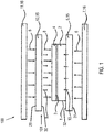
- Figures 8 to 11 considered in which a further embodiment of the intermediate element 15 is illustrated.
- Figure 8 shows a cross-sectional view (perpendicular to the surface element 17)
- Figure 9 likewise a cross-sectional view (perpendicular to the surface element 17, but perpendicular to the Figure 8)
- Figure 10 a supervision Figure 11 another supervision.
- Figure 8 shows a cross-sectional view (perpendicular to the surface element 17)
- Figure 9 likewise a cross-sectional view (perpendicular to the surface element 17, but perpendicular to the Figure 8)
- Figure 10 a supervision Figure 11 another supervision.
- the rods 24 consist, for example, of graphite, metal, ceramic, or glass ceramic.
- the rods 24 preferably have a rectangular cross section.
- a rectangular cross section with the short side parallel to the surface element 17 enables a high degree of rigidity with reduced shading to be achieved.
- the cross section of the rods 24 can also, depending on the material and construction, be advantageously circular (round rod), ring-shaped (tube), T-shaped (T-beam) or double-T-shaped (double-T beam).
- the rods 24 are advantageously made of a partially transparent, more preferably a transparent material.
- the absorption of the heating radiation in the rods 24 is preferably less than 20%, preferably less than 10%, and even more preferably less than 5%.
- This can advantageously be a ceramic adhesive.
- the attachment can also be carried out in a punctiform manner to reduce cold spots. If the thermal conductivity of the surface element 17 is high, but that of the connecting material is low, the effect of delayed heating can be minimized.
- the bars 24, which are oriented perpendicular to the plane of the surface element 17, can significantly stiffen the surface element 17. The mechanical requirements on the surface element 17 can thereby be reduced, so that the unsupported surface between the bars 24 is significantly reduced.
- the distance and the cross section of the rods 24 should be optimized so that the bending tensile strength of the surface element 17 is sufficient to withstand the pressure loads on the cantilever surface between two rods 24.
- the total mass of the number, distance and cross section of the rods 24 should only be chosen as large as necessary. It goes without saying that the bars 24 which are perpendicular to the surface element 17 represent a far better optimization of mass and rigidity than just a flat plate.
- the surface element 17 with a bar grid 25 or a line arrangement 26 made of bars 24 forms a composite body with significantly higher rigidity and low mass.
- Figure 13 the method for the heat treatment of a multilayer body 1 is illustrated. It comprises a first step S1, in which the multilayer body 1 is provided in a device 100 according to the invention for the heat treatment of a multilayer body 1, and a second step S2, in which the multilayer body 1 is irradiated with heating radiation on the bottom and lid sides. The respective radiant heat hits the lid and bottom of the Device for forming a (reduced) process space.
- the invention provides an improved arrangement, device and method for the heat treatment of a multilayer body, in which the mass of at least one intermediate element can be considerably reduced.
- the intermediate element either has a surface element in the form of a flexible film, or a surface element which is in the form of a flexible film or a thin rigid plate and is mechanically supported by a support device.
- the reduced mass can save costs in the heat treatment of the multilayer body without impairing the mechanical stability and corrosion resistance of the intermediate element.
Abstract
Die Erfindung betrifft eine Anordnung (102) zum Wärmebehandeln eines Mehrschichtkörpers (1), welche eine Energiequelle (16, 7, 11) mit mindestens einem Heizstrahler zur Erzeugung einer Heizstrahlung (6, 8), einen Mehrschichtkörper (1), und ein zwischen der Energiequelle (16, 7, 11) und dem Mehrschichtkörper (1) angeordnetes Zwischenelement (15, 5, 12) umfasst. Gemäß einer ersten Alternative umfasst das Zwischenelement (15, 5, 12) ein in Form einer biegsamen Folie (18) ausgebildetes Flächenelement (17). Gemäß einer zweiten Alternative umfasst das Zwischenelement (15, 5, 12) ein in Form einer biegsamen Folie (18) oder starren Platte (19) ausgebildetes Flächenelement (17), wobei das Flächenelement (17) eine der Energiequelle (16, 7, 11) zugewandte Fläche (27) aufweist, die von der Heizstrahlung (6, 8) bestrahlt werden kann, wobei die der Energiequelle (16, 7, 11) zugewandte Fläche (27) durch eine Stützeinrichtung (22, 23, 25, 26) in Richtung zur Energiequelle (16, 7, 11) mechanisch abgestützt ist.The invention relates to an arrangement (102) for heat treatment of a multi-layer body (1), which has an energy source (16, 7, 11) with at least one radiant heater for generating heating radiation (6, 8), a multi-layer body (1), and a between the Energy source (16, 7, 11) and the multilayer body (1) arranged intermediate element (15, 5, 12) comprises. According to a first alternative, the intermediate element (15, 5, 12) comprises a surface element (17) in the form of a flexible film (18). According to a second alternative, the intermediate element (15, 5, 12) comprises a surface element (17) in the form of a flexible film (18) or rigid plate (19), the surface element (17) being one of the energy sources (16, 7, 11 ) has facing surface (27) which can be irradiated by the heating radiation (6, 8), the surface (27) facing the energy source (16, 7, 11) being supported by a support device (22, 23, 25, 26) in Direction to the energy source (16, 7, 11) is mechanically supported.
Description
Die vorliegende Erfindung liegt auf dem technischen Gebiet der Herstellung von Dünnschichtsolarmodulen und betrifft eine Anordnung, eine Vorrichtung und ein Verfahren zur thermischen Behandlung eines Mehrschichtkörpers für ein Dünnschichtsolarmodul.The present invention lies in the technical field of the production of thin-film solar modules and relates to an arrangement, an apparatus and a method for the thermal treatment of a multilayer body for a thin-film solar module.
Photovoltaische Schichtensysteme für die Fertigung von Dünnschichtsolarmodulen sind dem Fachmann wohlbekannt. Die Materialien der Schichten, insbesondere das halbleitende Material der zur photoelektrischen Konversion eingesetzten Absorberschicht, werden so gewählt, dass das einfallende Sonnenlicht mit einem zufriedenstellenden Wirkungsgrad in elektrischen Strom umgewandelt werden kann. Aufgrund der physikalischen Eigenschaften und der technologischen Handhabbarkeit sind Absorberschichten aus amorphem, mikromorphem oder polykristallinem Silizium, Cadmium-Tellurid (CdTe), Gallium-Arsenid (GaAs), Kupfer-Indium/Gallium-Diselenid/Disulfid/Disulfoselenid (Cu(In,Ga) (S,Se)2), Kupfer-Zink-Zinn-Sulfo-Selenid (CZTS aus der Gruppe der Kesterite) und organischen Halbleitern in besonderer Weise geeignet. Der pentenäre Halbleiter Cu(In,Ga) (S,Se)2, der zur Gruppe der Chalkopyrit-Verbindungshalbleiter gehört, hat in der industriellen Serienfertigung von Dünnschichtsolarmodulen besondere Bedeutung erlangt.Photovoltaic layer systems for the production of thin-film solar modules are well known to the person skilled in the art. The materials of the layers, in particular the semiconducting material of the absorber layer used for photoelectric conversion, are selected so that the incident sunlight can be converted into electrical current with a satisfactory efficiency. Due to the physical properties and the technological handling, absorber layers made of amorphous, micromorphous or polycrystalline silicon, cadmium telluride (CdTe), gallium arsenide (GaAs), copper indium / gallium diselenide / disulfide / disulfoselenide (Cu (In, Ga) (S, Se) 2 ), copper-zinc-tin-sulfo-selenide (CZTS from the kesterite group) and organic semiconductors are particularly suitable. The pentenary semiconductor Cu (In, Ga) (S, Se) 2 , which belongs to the group of chalcopyrite compound semiconductors, has become particularly important in the industrial series production of thin-film solar modules.
Ein mögliches Verfahren zur Herstellung von Absorberschichten aus Cu(In,Ga)(S,Se)2 besteht aus einem Zweistufenprozess. Solche zweistufigen Verfahren sind beispielsweise aus
Die Wärmebehandlung des beschichteten Substrats erfolgt beispielsweise in In-Line-Anlagen, bei denen das beschichtete Substrat nacheinander verschiedenen Kammern zugeführt wird, die entlang einer Prozesstraße angeordnet sind. In einem typischen Aufbau umfasst eine solche In-Line-Anlage eine Ladestation, Heizkammern, in denen die beschichteten Substrate mit Aufheizgeschwindigkeiten von mehreren °C/s schnell erwärmt werden, sowie Kühlkammern, in denen die beschichteten Substrate abgekühlt und aus der Anlage ausgeschleust werden.The heat treatment of the coated substrate takes place, for example, in in-line systems, in which the coated substrate is successively fed to different chambers which are arranged along a process line. In a typical construction, such an in-line system comprises a charging station, heating chambers in which the coated substrates are heated rapidly at heating rates of several ° C./s, and cooling chambers in which the coated substrates are cooled and discharged from the system.
Die Wärmebehandlung des beschichteten Substrats ist ein kostenintensiver und technisch anspruchsvoller Prozess, der hohe Temperaturen, einen genauen Temperaturverlauf und eine definierte Zusammensetzung der Prozessatmosphäre erfordert, wenn hohe Wirkungsgrade mit ausreichend guter Reproduzierbarkeit erreicht werden sollen. So müssen beispielsweise bei der Fertigung hochwertiger Cu(In,Ga) (S,Se)2-Verbindungshalbleiter der Dampfdruck und die Stoffmenge Selens (Se) in der Prozessatmosphäre gut kontrolliert werden. Eine ausreichende Se-Menge ist nötig, um eine vollständige Selenisierung des metallischen Precursors zu gewährleisten. Deutlicher Se-Verlust würde zu einer unvollständigen Umwandlung des Precursors zum Verbindungshalbleiter führen. Selbst ein schwacher Se-Verlust kann noch zu Rekombination, d.h. Wirkungsgradverlust, und verstärkten Transienten (insbesondere Damp-Heat-Verluste) im fertigen Dünnschichtsolarmodul führen.The heat treatment of the coated substrate is a cost-intensive and technically demanding process that requires high temperatures, a precise temperature profile and a defined composition of the process atmosphere if high efficiencies with sufficiently good reproducibility are to be achieved. For example, in the production of high-quality Cu (In, Ga) (S, Se) 2 compound semiconductors, the vapor pressure and the amount of selenium (Se) in the process atmosphere must be carefully controlled. A sufficient amount of Se is necessary to ensure complete selenization of the metallic precursor. Significant Se loss would lead to an incomplete conversion of the precursor to the compound semiconductor. Even a weak Se loss can still lead to recombination, ie loss of efficiency, and increased transients (in particular steam-heat losses) in the finished thin-film solar module.
Zur besseren Kontrolle der Parameter des Wärmebehandlungsprozesses ist es bekannt, den Prozessraum für das beschichtete Substrat durch eine Prozessbox zu begrenzen. Hierdurch kann der Partialdruck der leicht flüchtigen Chalkogenkomponenten wie Selen oder Schwefel während der Wärmebehandlung weitestgehend konstant gehalten werden. Außerdem wird die Exposition der Prozesskammer mit korrosiven Gasen reduziert. Selen und Schwefel sind äußerst korrosive Stoffe, die Metalle bei den bei der Wärmebehandlung erforderlichen hohen Temperaturen stark angreifen.To better control the parameters of the heat treatment process, it is known to limit the process space for the coated substrate by means of a process box. As a result, the partial pressure of the volatile chalcogen components such as selenium or sulfur can be kept largely constant during the heat treatment. In addition, the Process chamber exposure to corrosive gases reduced. Selenium and sulfur are extremely corrosive substances that strongly attack metals at the high temperatures required for heat treatment.
Die Erwärmung des beschichteten Substrats erfolgt typischer Weise durch elektrisch betriebene Heizstrahler, die deckel- und bodenseitig der Prozessbox angeordnet sind, wobei die Heizstrahlung (sichtbares Licht bis Infrarot) auf Deckel und Boden der Prozessbox gerichtet ist. Für Deckel und Boden haben sich Glaskeramikplatten bewährt, da sie hochtemperaturfest, unempfindlich gegenüber Temperaturgradienten und inert gegenüber Korrosion durch Selen oder Schwefel sind, einen sehr niedrigen Ausdehnungskoeffizienten aufweisen und eine hohe mechanische Stabilität besitzen. Der Rahmen besteht typischer Weise aus Graphit oder einem Verbundwerkstoff wie ein kohlenstofffaserverstärkter Kohlenstoff (CFRC = Carbon-Fiber-Reinforced Carbon, RCC = Reinforced Carbon-Carbon, CFC = Carbon Fiber Carbon Composite).The coated substrate is typically heated by electrically operated radiant heaters which are arranged on the top and bottom of the process box, the radiant heat (visible light to infrared) being directed at the lid and bottom of the process box. Glass-ceramic plates have proven themselves for the lid and base, since they are resistant to high temperatures, insensitive to temperature gradients and inert to corrosion by selenium or sulfur, have a very low coefficient of expansion and have high mechanical stability. The frame typically consists of graphite or a composite material such as a carbon fiber reinforced carbon (CFRC = Carbon-Fiber-Reinforced Carbon, RCC = Reinforced Carbon-Carbon, CFC = Carbon Fiber Carbon Composite).
Die Verwendung einer Prozessbox erlaubt zwar eine zuverlässige Herstellung qualitativ hochwertiger Absorberschichten, jedoch ist der Energieverbrauch bei diesem Herstellungsprozess relativ hoch, da nicht nur das beschichtete Substrat, sondern auch die Prozessbox erwärmt wird. Mit jeweils 4 mm dicken Platten für Boden und Deckel beträgt allein deren Masse jeweils bereits etwa das Vierfache des beschichteten Substrats. Bei einem Substrat mit einer Größe von etwa 1 m2 (entspricht 5 kg bei 2 mm Dicke) beträgt das Gesamtgewicht der Prozessbox mit Rahmen ca 40 kg. Diese Masse wird während der thermischen Umsetzung des Precursors bis auf Prozesstemperatur aufgeheizt und muss anschließend wieder abgekühlt werden. Dies ist nachteilig, da es für eine nachhaltige und kostengünstige Herstellungsweise von Dünnschichtsolarmodulen wünschenswert ist, den Energieverbrauch so niedrig wie möglich zu halten.The use of a process box allows reliable production of high-quality absorber layers, but the energy consumption in this production process is relatively high since not only the coated substrate but also the process box is heated. With 4 mm thick plates for the base and lid, their mass alone is already about four times the coated substrate. In the case of a substrate with a size of approximately 1 m 2 (corresponds to 5 kg with a thickness of 2 mm), the total weight of the process box with frame is approximately 40 kg. This mass is heated up to the process temperature during the thermal conversion of the precursor and then has to be cooled again. This is disadvantageous since it is desirable for a thin film solar module to be produced in a sustainable and cost-effective manner to keep the energy consumption as low as possible.
Zudem müssen generelle Anforderungen an eine Prozessbox erfüllt sein, nämlich ein schneller Energieeintrag in den Innenraum, der Heizraten des Precursors von mehreren °C/s erlaubt, sowie eine ausreichende mechanische Robustheit, um den Transport eines beschichteten Substrats (typischer Weise ca. 5 kg/m2) zu gewährleisten und leichte Über- oder Unterdrücke während Spül- und Abpumpprozesse und während der konvektiven Kühlung auszuhalten. Die mechanischen Belastungen liegen hierbei in der Größenordnung von bis zu 40 kg/m2 (ohne Eigengewicht). Die Belastungen erfordern insbesondere eine hohe Biegezugfestigkeit des eingesetzten Materials. Des Weiteren muss die Prozessbox hinreichend mechanisch steif sein, so dass sich das Volumen des Prozessraums nicht signifikant ändert, beispielsweise durch elastische oder plastische Verformung während der Wärmebehandlung des beschichteten Substrats.In addition, general requirements for a process box must be met, namely a quick energy input into the interior, which allows the precursor to heat up to several ° C / s, and sufficient mechanical robustness to transport a coated substrate (typically approx. 5 kg / m 2 ) and to withstand slight overpressures or underpressures during flushing and draining processes and during convective cooling. The mechanical loads are of the order of up to 40 kg / m 2 (without dead weight). The loads in particular require a high bending tensile strength of the material used. Furthermore, the process box must be sufficiently mechanically stiff so that the volume of the process space does not change significantly, for example due to elastic or plastic deformation during the heat treatment of the coated substrate.
Die vorliegende Erfindung zielt auf vorstehende Aufgaben ab, wobei die im Stand der Technik bekannten Vorrichtungen zum Wärmebehandeln beschichteter Substrate in vorteilhafter Weise so weitergebildet werden sollen, dass eine energiesparende und kostengünstige Herstellung von Dünnschichtsolarmodulen in zuverlässiger Weise mit reproduzierbaren hohen Wirkungsgaden ermöglicht ist.The present invention aims at the above objects, wherein the devices for heat treatment of coated substrates known in the prior art are to be advantageously developed in such a way that an energy-saving and cost-effective production of thin-film solar modules is made possible in a reliable manner with reproducible high efficiencies.
Diese und weitere Aufgaben werden nach dem Vorschlag der Erfindung durch eine Anordnung, eine Vorrichtung und ein Verfahren zum Wärmebehandeln eines Mehrschichtkörpers mit den Merkmalen der unabhängigen und nebengeordneten Ansprüche gelöst. Bevorzugte Ausführungen gehen aus den Unteransprüchen hervor.According to the proposal of the invention, these and other objects are achieved by an arrangement, a device and a method for the heat treatment of a multilayer body with the features of the independent and independent claims. Preferred statements emerge from the subclaims.
Erfindungsgemäß ist eine Anordnung und eine Vorrichtung zum Wärmebehandeln eines Mehrschichtkörpers gezeigt. Der Ausdruck "Mehrschichtkörper" beschreibt im Sinne der Erfindung ein Substrat, z.B. ein Glassubstrat, mit einer oder mehreren darauf aufgebrachten Schichten, die einer Wärmebehandlung zu unterziehen sind.According to the invention, an arrangement and a device for the heat treatment of a multilayer body are shown. In the context of the invention, the term “multilayer body” describes a substrate, for example a glass substrate, with one or more layers applied thereon which are to be subjected to a heat treatment.
Der Mehrschichtkörper dient zur Herstellung eines Dünnschichtsolarmoduls. Vorzugsweise handelt es sich um ein Dünnschichtsolarmodul mit Verbundscheibenstruktur, welches über eine Deckplatte und ein rückseitiges Substrat (z.B. Glasplatten) verfügt, die durch eine thermoplastische oder vernetzende Polymer-Zwischenschicht (z.B. PVB oder EVA) fest miteinander verbunden sind. Die Erfindung bezieht sich insbesondere auf einen Mehrschichtkörper für ein Dünnschichtsolarmodul in Substratkonfiguration, bei der der Schichtenaufbau zur Herstellung der Solarzellen auf einer der Lichteintrittsseite zugewandten Oberfläche des rückseitigen Substrats aufgebracht ist, oder in Superstratkonfiguration, bei welcher der Schichtenaufbau auf einer von der Lichteintrittsseite abgewandten Oberfläche der transparenten Deckplatte aufgebracht ist.The multilayer body is used to manufacture a thin-film solar module. It is preferably a thin-film solar module with a composite pane structure, which has a cover plate and a rear substrate (e.g. glass plates), which are firmly connected to one another by a thermoplastic or cross-linking polymer intermediate layer (e.g. PVB or EVA). The invention relates in particular to a multilayer body for a thin-film solar module in a substrate configuration in which the layer structure for producing the solar cells is applied to a surface of the rear substrate facing the light entry side, or in a superstrate configuration in which the layer structure is applied to a surface facing away from the light entry side transparent cover plate is applied.
In Einklang mit der üblichen Verwendung bezieht sich der Begriff "Dünnschichtsolarmodul" auf Module mit einem Schichtenaufbau mit einer geringen Dicke von beispielsweise einigen Mikrometern, welche einen Träger für eine ausreichende mechanische Festigkeit benötigen. Der Träger kann beispielsweise aus Glas, Kunststoff, Metall oder einer Metallegierung bestehen und in Abhängigkeit von der jeweiligen Schichtdicke und den spezifischen Materialeigenschaften als starre Platte oder biegsame Folie ausgestaltet sein.In accordance with the usual use, the term “thin-film solar module” refers to modules with a layer structure with a small thickness of, for example, a few micrometers, which require a carrier for sufficient mechanical strength. The carrier can consist, for example, of glass, plastic, metal or a metal alloy and, depending on the respective layer thickness and the specific material properties, can be designed as a rigid plate or flexible film.
Bei einem Dünnschichtsolarmodul umfasst der Schichtenaufbau in an sich bekannter Weise eine Rückelektrodenschicht, eine Frontelektrodenschicht, und eine zwischen Rück- und Frontelektrodenschicht angeordnete, fotovoltaisch aktive Absorberschicht. Die Frontelektrodenschicht ist optisch transparent, da ein Durchtritt von Licht zum Schichtenaufbau ermöglicht sein muss. Die Frontelektrodenschicht umfasst oder besteht typischer Weise aus einem dotierten Metalloxid (TCO = Transparent Conductive Oxide), beispielsweise n-leitendes, insbesondere Aluminium-dotiertes, Zinkoxid (AZO).In the case of a thin-film solar module, the layer structure comprises, in a manner known per se, a back electrode layer, a front electrode layer, and a photovoltaically active absorber layer arranged between the back and front electrode layers. The front electrode layer is optically transparent, since light must pass through to build up the layer. The front electrode layer typically comprises or consists of a doped metal oxide (TCO = Transparent Conductive Oxide), for example n-type, in particular aluminum-doped, zinc oxide (AZO).
Vorzugsweise weist der Mehrschichtkörper einen Schichtenstapel (Precursor) zur Herstellung eines chalkogenhaltiges Halbleitermaterials auf. Als Chalkogene werden die Elemente der 6. Hauptgruppe des Periodensystems bezeichnet. Das Halbleitermaterial der Absorberschicht enthält mindestens ein Chalkogen, vorzugsweise Schwefel und/oder Selen. Besonders bevorzugt ist dies ein chalkogenhaltiger Chalkopyrit-Verbindungshalbleiter, bei dem es sich vorteilhaft um einen ternären I-III-VI-Verbindungshalbleiter aus der Gruppe Kupfer-Indium/Gallium-Disulfid/Diselenid handelt, abgekürzt durch die Formel Cu(In,Ga)(S,Se)2. In vorstehender Formel können Indium und Gallium jeweils allein oder in Kombination vorliegen. Entsprechendes gilt für die Chalkogene Schwefel und Selen, die jeweils allein oder in Kombination vorliegen können. Als Material für die Absorberschicht eignet sich in besonderer Weise CISe (Kupfer-Indium-Diselenid), CIS (Kupfer-Indium-Disulfid), CIGSe (Kupfer-Indium-Gallium-Diselenid) CIGS (Kupfer-Indium-Gallium-Disulfid) oder CIGS-Se (Kupfer-Indium-Gallium-Disulfoselenid). Gleichermaßen bevorzugt kann der Mehrschichtkörper einen Schichtenstapel (Precursor) zur Herstellung eines chalkogenhaltigen Kesterit-Verbindungshalbleiters, vorzugsweise Kupfer-Zink-Zinn-Sulfoselenid (CZTS) aufweisen. Der chalkogenhaltige Kesterit-Verbindungshalbleiter enthält mindestens ein Chalkogen, vorzugsweise Schwefel und/oder Selen.The multilayer body preferably has a layer stack (precursor) for producing a chalcogen-containing semiconductor material. The elements of the 6th main group of the periodic table are called chalcogens. The semiconductor material of the absorber layer contains at least one chalcogen, preferably sulfur and / or selenium. This is particularly preferably a chalcogen-containing chalcopyrite compound semiconductor, which is advantageously a ternary I-III-VI compound semiconductor from the group copper-indium / gallium disulfide / diselenide, abbreviated by the formula Cu (In, Ga) ( S, Se) 2 . In the above formula, indium and gallium can each be used alone or in combination. The same applies to the chalcogens sulfur and selenium, which can be present alone or in combination. CISe (copper indium diselenide), CIS (copper indium disulfide), CIGSe (copper indium gallium diselenide) CIGS (copper indium gallium disulfide) or CIGS are particularly suitable as the material for the absorber layer -Se (copper indium gallium disulfoselenide). Similarly, the multilayer body can preferably have a layer stack (precursor) for producing a chalcogen-containing kesterite compound semiconductor, preferably copper-zinc-tin sulfoselenide (CZTS). The chalcogen-containing compound semiconductor contains at least one chalcogen, preferably sulfur and / or selenium.
Zweckmäßig wird eine Cu(In,Ga) (S,Se)2-Absorberschicht auf einem Substrat in einem zweistufigen RTP-Prozess hergestellt. Hierbei wird, nach Herstellen einer Rückelektrodenschicht auf dem Substrat, zunächst eine Vorläuferschicht (Precursor) auf die Rückelektrodenschicht aufgebracht. Die Vorläuferschicht, welche aus einer oder mehreren Lagen bestehen kann, enthält die Elemente Kupfer, Indium und Gallium, die vorzugsweise durch Sputtern aufgebracht werden. Des Weiteren enthält die Vorläuferschicht mindestens ein Chalkogen in elementarer Form, vorzugsweise Selen und/oder Schwefel, welches vorzugsweise durch thermisches Verdampfen aufgebracht wird. Bei diesen Abscheideprozessen liegt die Temperatur des Trägers typischer Weise unterhalb von 100 °C, so dass die Elemente im Wesentlichen als Metalllegierung und elementares Chalkogen (Selen und/oder Schwefel) unreagiert erhalten bleiben. Anschließend wird die Vorläuferschicht durch Erwärmen in einer mindestens ein Chalkogen (Selen und/oder Schwefel) enthaltenden Atmosphäre zu einem Cu(In,Ga) (S,Se)2-Verbindungshalbleiter reagiert (thermisch umgesetzt). Beispielsweise enthält die Vorläuferschicht als Chalkogen nur elementares Selen und die thermische Umsetzung der Vorläuferschicht erfolgt in einer Atmosphäre, die als Chalkogen nur Schwefel enthält. Durch die Wärmebehandlung der Vorläuferschicht findet eine Kristallbildung und Phasenumwandlung der Vorläuferschicht zur Halbleiterschicht (Verbindungshalbleiter) statt. In entsprechender Weise kann in einem zweistufigen Verfahren ein chalkogenhaltiger Kesterit-Verbindungshalbleiter hergestellt werden, wobei zunächst eine Vorläuferschicht auf die Rückelektrodenschicht aufgebracht wird, die Kupfer, Zink, Zinn und mindestens ein Chalkogen (vorzugsweise Schwefel und/oder Selen, besonders bevorzugt nur Selen) enthält. Anschließend wird die Vorläuferschicht durch Erwärmen in einer Atmosphäre, welche mindestens ein Chalkogen (vorzugsweise Schwefel und/oder Selen, besonders bevorzugt nur Schwefel) enthält, zum Verbindungshalbleiter umgesetzt.A Cu (In, Ga) (S, Se) 2 absorber layer is expediently produced on a substrate in a two-stage RTP process. Here, after producing a back electrode layer on the substrate, a precursor layer is first applied to the back electrode layer. The precursor layer, which can consist of one or more layers, contains the elements copper, indium and gallium, which are preferably applied by sputtering. Furthermore, the precursor layer contains at least one chalcogen in elemental form, preferably selenium and / or sulfur, which is preferably applied by thermal evaporation. With these deposition processes the temperature of the carrier is typically below 100 ° C., so that the elements remain essentially unreacted as metal alloy and elemental chalcogen (selenium and / or sulfur). The precursor layer is then reacted by heating in an atmosphere containing at least one chalcogen (selenium and / or sulfur) to give a Cu (In, Ga) (S, Se) 2 compound semiconductor (thermally converted). For example, the precursor layer contains only elemental selenium as chalcogen, and the thermal conversion of the precursor layer takes place in an atmosphere which contains only sulfur as chalcogen. The heat treatment of the precursor layer causes crystal formation and phase transformation of the precursor layer to the semiconductor layer (compound semiconductor). In a corresponding manner, a chalcogenite-containing compound semiconductor can be produced in a two-stage process, a precursor layer containing copper, zinc, tin and at least one chalcogen (preferably sulfur and / or selenium, particularly preferably only selenium) being first applied to the back electrode layer . The precursor layer is then converted to the compound semiconductor by heating in an atmosphere which contains at least one chalcogen (preferably sulfur and / or selenium, particularly preferably only sulfur).
Die erfindungsgemäße Anordnung zum Wärmebehandeln eines Mehrschichtkörpers umfasst eine Energiequelle mit mindestens einem Heizstrahler (z.B. ein Strahlerfeld mit einer ein- oder zweidimensionalen Anordnung von Heizstrahlern) zur Erzeugung einer Heizstrahlung, einen Mehrschichtkörper, sowie ein zwischen der Energiequelle und dem Mehrschichtkörper angeordnetes Zwischenelement, auf welches die Heizstrahlung trifft.The arrangement according to the invention for the heat treatment of a multilayer body comprises an energy source with at least one radiant heater (e.g. a radiator array with a one- or two-dimensional arrangement of radiant heaters) for generating radiant heat, a multilayer body, and an intermediate element arranged between the energy source and the multilayer body, on which the Radiant heat hits.
Gemäß einer ersten Alternative umfasst das Zwischenelement ein in Form einer biegsamen Folie ausgebildetes Flächenelement. Gemäß einer zweiten Alternative umfasst das Zwischenelement ein Flächenelement, dass in Form einer biegsamen Folie oder einer starren Platte ausgebildet ist, wobei auf einer der Energiequelle zugewandten Seite des Flächenelements eine Stützeinrichtung zum mechanischen Abstützen des Flächenelements in Richtung zur Energiequelle angeordnet ist. Konkret wird eine der Energiequelle zugewandte Fläche des Flächenelements, welche von der Heizstrahlung der Energiequelle bestrahlt werden kann, von der Stützeinrichtung in Richtung der Energiequelle mechanisch abgestützt. Beispielsweise besteht das Zwischenelement nur aus dem Flächenelement oder setzt sich aus dem Flächenelement und der Stützeinrichtung zusammen.According to a first alternative, the intermediate element comprises a surface element designed in the form of a flexible film. According to a second alternative, the intermediate element comprises a surface element which is designed in the form of a flexible film or a rigid plate, a support device for mechanically supporting the surface element in the direction of the energy source being arranged on a side of the surface element facing the energy source. Specifically, a surface of the surface element facing the energy source, which can be irradiated by the heating radiation of the energy source, is mechanically supported by the support device in the direction of the energy source. For example, the intermediate element consists only of the surface element or is composed of the surface element and the support device.
Im Sinne vorliegender Erfindung bezeichnet der Begriff "Flächenelement" einen flächig-ebenen Körper, beispielsweise mit Rechteckform. Das Flächenelement weist eine der Energiequelle zugewandte erste Fläche auf, die von der Heizstrahlung der Energiequelle direkt bestrahlt werden kann. Die von der Heizstrahlung direkt bestrahlte Fläche kann der ersten Fläche des Flächenelements entsprechen, aber auch kleiner sein. Gegenüberliegend zur ersten Fläche weist das Flächenelement eine von der Energiequelle abgewandte zweite Fläche auf, welche bei der Verwendung des Zwischenelements als Boden auch als Auflagefläche für den Mehrschichtkörper dienen kann.In the sense of the present invention, the term “surface element” denotes a flat, flat body, for example with a rectangular shape. The surface element has a first surface which faces the energy source and which can be directly irradiated by the heating radiation of the energy source. The surface directly irradiated by the heating radiation can correspond to the first surface of the surface element, but can also be smaller. Opposite the first surface, the surface element has a second surface facing away from the energy source, which, when the intermediate element is used as a base, can also serve as a support surface for the multilayer body.
In der erfindungsgemäßen Anordnung zum Wärmebehandeln eines Mehrschichtkörpers sind die Energiequelle und das Zwischenelement so angeordnet, dass der Mehrschichtkörper direkt durch Heizstrahlung (bei einem für die Heizstrahlung transparenten oder teiltransparenten Flächenelement) oder indirekt durch das aufgeheizte Flächenelement (bei einem für die Heizstrahlung opaken Flächenelement) aufgeheizt werden kann. Bei direkter Aufheizung passiert zumindest ein Teil der Heizstrahlung der Energiequelle das Flächenelement und trifft auf den Mehrschichtkörper, wodurch der Mehrschichtkörper aufgeheizt wird. Bei indirekter Aufheizung wird das Flächenelement durch die auftreffende Heizstrahlung der Energiequelle aufgeheizt und gibt die Wärme über Wärmestrahlung und Wärmeleitung an den Mehrschichtkörper ab. Falls das Flächenelement opak ist, erfolgt eine Heizung des Mehrschichtkörpers im Wesentlichen indirekt durch das erwärmte Flächenelement mittels Wärmestrahlung und Wärmeleitung. Das Flächenelement hat vorzugsweise eine geringe Reflektivität und eine hohe Emissivität, damit die vom Strahlerfeld emittierte Strahlung weitestgehend absorbiert wird.In the arrangement according to the invention for the heat treatment of a multilayer body, the energy source and the intermediate element are arranged in such a way that the multilayer body is heated directly by radiant heat (in the case of a surface element which is transparent or partially transparent for the radiant heat) or indirectly by the heated surface element (in the case of a surface element which is opaque for the radiant heat) can be. In the case of direct heating, at least part of the heating radiation from the energy source passes through the surface element and strikes the multilayer body, as a result of which the multilayer body is heated. With indirect heating, the surface element is affected by the incident radiation The energy source is heated up and emits the heat to the multilayer body via heat radiation and heat conduction. If the surface element is opaque, the multilayer body is heated essentially indirectly by the heated surface element by means of heat radiation and heat conduction. The surface element preferably has a low reflectivity and a high emissivity, so that the radiation emitted by the radiation field is largely absorbed.
Im Sinne vorliegender Erfindung bezieht sich der Begriff "Transparenz" bzw. "transparent" auf eine Durchlässigkeit für Heizstrahlung von wenigstens 85%, insbesondere wenigstens 90%, vorzugsweise wenigstens 95%, insbesondere 100%. Der Begriff "Opazität" bzw. "opak" bezieht sich auf eine Durchlässigkeit für Heizstrahlung von weniger als 5%, insbesondere 0%. Der Begriff "Teiltransparenz" bzw. "teiltransparent" bezieht sich auf eine Durchlässigkeit für Heizstrahlung die zwischen jener der Opazität und Transparenz liegt.In the sense of the present invention, the term “transparency” or “transparent” refers to a permeability to radiant heat of at least 85%, in particular at least 90%, preferably at least 95%, in particular 100%. The term "opacity" or "opaque" refers to a permeability to radiant heat of less than 5%, in particular 0%. The term "partial transparency" or "partially transparent" refers to a permeability to radiant heat that lies between that of opacity and transparency.
Das Flächenelement ist gemäß der ersten Alternative als biegsame Folie ausgebildet oder gemäß der zweiten Alternative als biegsame Folie oder dünne starre Platte mit mechanischer Stützeinrichtung ausgebildet. Erfindungsgemäß kann das Zwischenelement so ausgebildet sein, dass es eine geringere Masse aufweist als im Stand der Technik eingesetzte Zwischenelemente, was in vorteilhafter Weise eine erhebliche Einsparung von Energiekosten bei der Wärmebehandlung des Mehrschichtkörpers ermöglicht. Da das Flächenelement sehr dünn ausgebildet sein kann, sind zudem auch opake Materialen für das Flächenelement verwendbar, da die gewünschten hohen Heizraten von einigen °C pro Sekunde nur mit sehr dünnen Flächenelementen erreicht werden können.According to the first alternative, the surface element is designed as a flexible film or, according to the second alternative, as a flexible film or thin rigid plate with a mechanical support device. According to the invention, the intermediate element can be designed such that it has a lower mass than the intermediate elements used in the prior art, which advantageously enables considerable savings in energy costs during the heat treatment of the multilayer body. Since the surface element can be made very thin, opaque materials can also be used for the surface element, since the desired high heating rates of a few ° C per second can only be achieved with very thin surface elements.
Vorzugsweise weist das Flächenelement eine solche (geringe) Dicke auf, dass ein Formfaktor, gegeben durch den Quotienten aus Dicke/Diagonale des Flächenelements, weniger als 4 mm/1 m, also weniger als 4 x 10⁻³, beträgt. Hier wird ein rechteckförmiges Flächenelement mit einer Diagonalen der der Energiequelle zugewandten ersten Fläche betrachtet. Vorzugsweise weist das Flächenelement eine solche Dicke auf, dass der Formfaktor weniger als 5 x 10⁻⁴ beträgt. Dies gilt insbesondere für den Fall, dass die Transmission des Flächenelements weniger als 20%, weniger als 5% oder weniger als 1% ist, was schnelle Heizraten des Mehrschichtkörpers ermöglicht. Ist die Transmission des Flächenelements größer als 50% oder sogar größer als 70%, kann der Formfaktor auch größer sein.The surface element preferably has such a (small) thickness that a form factor, given by the quotient of the thickness / diagonal of the surface element, is less than 4 mm / 1 m, i.e. less than 4 x 10 -3 . Here, a rectangular surface element with a diagonal of the first surface facing the energy source is considered. The surface element preferably has a thickness such that the form factor is less than 5 × 10 -4 . This applies in particular to the case where the transmission of the surface element is less than 20%, less than 5% or less than 1%, which enables fast heating rates of the multilayer body. If the transmission of the surface element is greater than 50% or even greater than 70%, the form factor can also be greater.
Vorzugsweise beträgt die Dicke des Flächenelements weniger als 4 mm, stärker bevorzugt weniger als 1 mm, noch stärker bevorzugt weniger als 0,5 mm.The thickness of the surface element is preferably less than 4 mm, more preferably less than 1 mm, even more preferably less than 0.5 mm.
Vorzugsweise ist die gesamte Masse des Zwischenelements so gewählt, dass sie weniger als 400%, vorzugsweise weniger als 200%, stärker bevorzugt weniger als 100%, noch stärker bevorzugt weniger als 50%, am stärksten bevorzugt weniger als 10%, der Masse des Mehrschichtkörpers beträgt. Hierdurch können bei der Wärmebehandlung des Mehrschichtkörpers Energiekosten in erheblichen Umfang eingespart werden.The total mass of the intermediate element is preferably selected such that it is less than 400%, preferably less than 200%, more preferably less than 100%, even more preferably less than 50%, most preferably less than 10%, of the mass of the multilayer body is. As a result, energy costs can be saved to a considerable extent in the heat treatment of the multilayer body.
Falls das Flächenelement in Form einer nicht formstabilen, d.h. biegsamen, Folie ausgebildet ist, beträgt die Dicke der Folie vorzugsweise weniger als 0,5 mm, stärker bevorzugt weniger als 0,3 mm.If the surface element is in the form of a non-dimensionally stable, i.e. flexible film is formed, the thickness of the film is preferably less than 0.5 mm, more preferably less than 0.3 mm.
Vorzugsweise enthält oder besteht die Folie aus Graphit mit oder ohne Korrosionsinhibitor, welche reißfest und korrosionsbeständig ist. Vorzugsweise enthält oder besteht die Folie aus einem Verbundwerkstoff, wie beispielsweise ein kohlenstofffaserverstärkter Kohlenstoff. Möglich ist auch, dass die Folie eine ein- oder beidseitig mit einer Korrosionsschutzschicht beschichtete Metallfolie ist. Die Beschichtung der Metallfolie ist hierdurch resistent gegen Korrosion bei hohen Temperaturen. Ein Beispiel hierfür ist eine Molybdän-Folie, die beidseitig mit einer z.B. 20 bis 1000 nm dicken Molybdän-Nitrid (MoN)-Schicht beschichtet ist, die als Korrosionsschutzschicht dient. Möglich sind auch andere keramische Korrosionsschutzschichten, beispielsweise aus SiC, Al2O3, TiN usw. Metallfolien sind mechanisch sehr stabil hinsichtlich Biegezugfestigkeit und Reißfestigkeit. Sie können deshalb sehr dünn sein. Die hohe Wärmeleitfähigkeit sorgt für eine homogene Temperaturverteilung. Die Emissivität der Metallfolien sollte durch deren Beschichtung oder Oberflächenrauigkeit möglichst hoch sein und der Reflexionsgrad sehr gering. Die Korrosionsbeständigkeit wird durch die Korrosionsschutzschicht gewährleistet.The film preferably contains or consists of graphite with or without a corrosion inhibitor, which is tear-resistant and corrosion-resistant. The film preferably contains or consists of a composite material, such as, for example, a carbon fiber-reinforced carbon. It is also possible that the film is a metal film coated on one or both sides with a corrosion protection layer. The coating of the metal foil is therefore resistant to corrosion at high temperatures. An example of this is a molybdenum film which is coated on both sides with a 20 to 1000 nm thick molybdenum nitride (MoN) layer, which serves as a corrosion protection layer. Other ceramic corrosion protection layers, for example made of SiC, Al 2 O 3 , TiN etc., are also possible. Metal foils are mechanically very stable with regard to flexural tensile strength and tensile strength. You can therefore be very thin. The high thermal conductivity ensures a homogeneous temperature distribution. The emissivity of the metal foils should be as high as possible due to their coating or surface roughness and the reflectance should be very low. The corrosion protection layer is guaranteed by the corrosion protection layer.
Alternativ zu beschichteten Metallfolien sind auch Verbundfolien geeignet, beispielsweise eine Metallfolie, die durch einen Klebstoff (z.B. ein keramischer Klebstoff oder Graphitkleber) ein- oder beidseitig mit einer Graphitfolie verbunden ist. Die Funktion der Abdichtung und der Korrosionsstabilität übernimmt die Graphitfolie. Die mechanische Stabilität wird durch die Metallfolie erreicht.As an alternative to coated metal foils, composite foils are also suitable, for example a metal foil that is connected to a graphite foil on one or both sides by an adhesive (e.g. a ceramic adhesive or graphite adhesive). The graphite foil takes on the function of sealing and corrosion stability. The mechanical stability is achieved through the metal foil.
Falls das Flächenelement in Form einer starren Platte ausgebildet ist, beträgt die Dicke der Platte vorzugsweise weniger als 4 mm, stärker bevorzugt weniger als 1 mm, noch stärker bevorzugt weniger als 0,5 mm. Vorzugsweise enthält oder besteht die Platte aus Glaskeramik, kohlenstofffaserverstärkter Kohlenstoff oder einem Glas mit einem hohen Erweichungspunkt (typischer Weise höher als 800°C) wie Borosilikatglas, Aluminiumsilikatglas oder Quarzglas.If the surface element is in the form of a rigid plate, the thickness of the plate is preferably less than 4 mm, more preferably less than 1 mm, even more preferably less than 0.5 mm. The plate preferably contains or consists of glass ceramic, carbon fiber-reinforced carbon or a glass with a high softening point (typically higher than 800 ° C.) such as borosilicate glass, aluminum silicate glass or quartz glass.
Das in Form einer biegsamen Folie oder starren Platte ausgebildete Flächenelement hat vorzugsweise eine geringe Reflektivität und hohe Emissivität, damit die von der Energiequelle emittierte Strahlung weitestgehend absorbiert wird. Vorzugsweise hat das Flächenelement zur Energiequelle hin eine Reflexion von kleiner 10%, stärker bevorzugt kleiner 5% und am besten kleiner 2% (die prozentualen Angaben beziehen sich auf den Anteil der reflektierten Heizstrahlung) .The surface element in the form of a flexible film or rigid plate preferably has a low reflectivity and high emissivity, so that the radiation emitted by the energy source is largely absorbed. The surface element preferably has a reflection of less than 10% towards the energy source, more preferably less than 5% and most preferably less than 2% (the percentages relate to the proportion of reflected heating radiation).
Die zweite Fläche des in Form einer biegsamen Folie oder starren Platte ausgebildeten Flächenelements, die als Auflagefläche für einen Mehrschichtkörper dienen kann, ist vorzugsweise mit Erhebungen strukturiert, so dass die Kontaktfläche zum Mehrschichtkörper möglichst gering ist. Damit wird der Einfluss der Wärmeleitung unterdrückt. Die Wärmeleitung kann zu einem räumlich sehr inhomogenen Aufheizen führen, wenn sich der Mehrschichtkörper beim Aufheizen wölbt oder schon durch Vorprozesse nicht ganz plan ist. Die Strukturierung kann durch Aufrauen, lokale Entschichtung oder Beschichtung erfolgen. Die Strukturierung umfasst Erhebungen, die als statistische und/oder periodische Strukturen ausgebildet sein können, deren Abmessung senkrecht zum Flächenelement (Höhe) vorzugsweise im Bereich von einem bis mehreren Hundert Mikrometern liegt.The second surface of the surface element designed in the form of a flexible film or rigid plate, which can serve as a support surface for a multilayer body, is preferably structured with elevations, so that the contact surface with the multilayer body is as small as possible. This suppresses the influence of heat conduction. The heat conduction can lead to a spatially very inhomogeneous heating if the multilayer body bulges when heating or is not quite flat due to preliminary processes. The structuring can be done by roughening, local stripping or coating. The structuring comprises elevations which can be designed as statistical and / or periodic structures, the dimensions of which are perpendicular to the surface element (height), preferably in the range from one to several hundred micrometers.
Die Stützeinrichtung ist so ausgebildet, dass sie das Flächenelement bzw. die erste Fläche des Flächenelements in Richtung zur Energiequelle hin mechanisch abstützt. Die Stützeinrichtung ist zu diesem Zweck zwischen dem Flächenelement und der Energiequelle angeordnet. Die Stützeinrichtung stützt das Flächenelement vorzugsweise nicht vollflächig ab, d.h. eine Kontaktfläche der Stützeinrichtung, in dem die Stützeinrichtung Berührungskontakt mit der ersten Fläche hat, ist kleiner als die erste Fläche. Insbesondere ist die Stützeinrichtung somit nicht in Form einer Schicht oder Beschichtung ausgebildet, welche auf die erste Fläche des Flächenelements aufgebracht ist. Vorzugsweise bedeckt die Stützeinrichtung weniger als 10% der ersten Fläche des Flächenelements (in Sicht senkrecht durch das Flächenelement), so dass nur eine geringfügige Abschattung der auf das Flächenelement auftreffenden Heizstrahlung durch die Stützeinrichtung erfolgt. Der Mehrschichtkörper kann somit homogen aufgeheizt werden und es treten nur geringe thermische Inhomogenitäten auf. Beispielsweise haben das Flächenelement und die Stützeinrichtung nur losen Berührungskontakt, wobei die Stützeinrichtung der ersten Fläche des Flächenelements anliegt. Vorzugsweise sind das Flächenelement und die Stützeinrichtung fest miteinander verbunden. Beispielsweise ist die Stützeinrichtung mit der ersten Fläche des Flächenelements fest verbunden, beispielsweise durch einen Klebstoff, vorzugsweise durch einen keramischen Klebstoff. Vorzugsweise ist die Stützeinrichtung nur stellenweise, insbesondere punktweise, mit dem Flächenelement fest verbunden, um einen unerwünschten Wärmeübergang (Kältebrücken) zu minimieren.The support device is designed such that it mechanically supports the surface element or the first surface of the surface element in the direction of the energy source. For this purpose, the support device is arranged between the surface element and the energy source. The support device preferably does not support the surface element over the entire surface, ie a contact surface of the support device in which the support device is in contact with the first surface is smaller than the first surface. In particular, the support device is therefore not in the form of a layer or coating which is applied to the first surface of the surface element. The support device preferably covers less than 10% of the first surface of the surface element (in the view perpendicularly through the surface element), so that only a slight shading of the heating radiation impinging on the surface element is effected by the support device. The multilayer body can thus be heated up homogeneously and only slight thermal inhomogeneities occur. For example, the surface element and the support device have only loose contact, the support device being in contact with the first surface of the surface element. The surface element and the support device are preferably firmly connected to one another. For example, the support device is firmly connected to the first surface of the surface element, for example by an adhesive, preferably by a ceramic adhesive. The support device is preferably firmly connected to the surface element only in places, in particular at points, in order to minimize undesired heat transfer (cold bridges).
Die Kombination von Flächenelement und Stützeinrichtung ermöglicht gleichsam eine Entkopplung der Anforderungen an das Zwischenelement einerseits einen gasdichten Prozessraum mit geringer Masse zu formen und andererseits ausreichend mechanisch stabil sowie genügend beständig gegen die bei der Wärmebehandlung auftretenden korrosiven Substanzen zu sein. Insbesondere kann das Flächenelement hiebei gezielt im Hinblick auf die gasdichte Ausbildung des Prozessraums bei geringer Masse und Korrosionbeständigkeit optimiert werden, wobei durch die Stützeinrichtung eine ausreichende mechanische Stabilität gewährleistet wird.The combination of surface element and support device makes it possible to decouple the requirements for the intermediate element, on the one hand, to form a gas-tight process space with low mass and, on the other hand, to be sufficiently mechanically stable and sufficiently resistant to the corrosive substances that occur during heat treatment. In particular, the surface element can be specifically optimized with regard to the gas-tight design of the process space with a low mass and resistance to corrosion, the supporting device ensuring sufficient mechanical stability.
Gemäß einer bevorzugten Ausgestaltung der Erfindung ist die Stützeinrichtung in Form eines Gitters aus sich kreuzenden linienförmigen Stützelementen ausgebildet. Das Gitter weist eine oder vorzugsweise eine Vielzahl von Maschen auf. Vorteilhaft sind die linienförmigen Stützelemente im Gitter fest miteinander verbunden. Gemäß einer weiteren bevorzugten Ausgestaltung sind die linienförmigen Stützelemente in einer Linienanordnung angeordnet, wobei die linienförmigen Stützelemente nebeneinander liegend, insbesondere parallel, angeordnet sind. Durch die Stützeinrichtung kann einerseits eine gute mechanische Abstützung des Flächenelements erreicht werden. Andererseits sind Inhomogenitäten beim Aufheizen des Mehrschichtkörpers durch Abschirmen der Heizstrahlung relativ gering. Vorteilhaft erstreckt sich das Gitter bzw. die Linienanordnung über die komplette erste Fläche des Flächenelements (in senkrechter Sicht durch das Flächenelement), ohne jedoch Berührungskontakt mit der kompletten ersten Fläche zu haben.According to a preferred embodiment of the invention, the support device is designed in the form of a grid made of intersecting linear support elements. The grid has one or preferably a plurality of meshes. The linear support elements in the lattice are advantageously firmly connected to one another. According to a further preferred embodiment, the linear support elements are arranged in a line arrangement, the linear support elements being arranged next to one another, in particular in parallel. Good mechanical support of the surface element can be achieved on the one hand by the support device. On the other hand, inhomogeneities when heating the multilayer body by shielding the heating radiation are relatively low. This advantageously extends Grid or the line arrangement over the entire first surface of the surface element (in a vertical view through the surface element), but without being in contact with the entire first surface.
In Abhängigkeit der Dicke der linienförmigen Stützelemente kann deren Zahl im Hinblick auf die für die mechanische Abstützung geforderte Kraftaufnahme geeignet gewählt sein, wobei entweder eine geringere Zahl von dickeren Stützelementen oder eine größere Zahl von dünneren Stützelementen vorgesehen sein können. Je dünner die linienförmigen Stützelemente sind, desto geringer sind die hierdurch verursachten möglichen Abschattungen und Temperaturinhomogenitäten. Das in Form einer Folie oder dünnen Platte ausgebildete Flächenelement kann z.B. durch einen keramischen Kleber mit den linienförmigen Stützelementen verbunden sein.Depending on the thickness of the linear support elements, their number can be selected appropriately with regard to the force absorption required for the mechanical support, wherein either a smaller number of thicker support elements or a larger number of thinner support elements can be provided. The thinner the linear support elements, the lower the possible shadowing and temperature inhomogeneities caused by this. The surface element in the form of a film or thin plate can e.g. be connected to the linear support elements by a ceramic adhesive.
Vorteilhaft ist das Gitter aus linienförmigen Stützelementen ein Draht- oder Stabgitter, wobei die linienförmigen Stützelemente aus Metall oder einem anderen Material bestehen können. Optional bestehen die linienförmigen Stützelemente aus Metall, das mit einer Korrosionsschutzschicht beschichtet ist. Beispielsweise enthalten oder bestehen die Metalldrähte aus einer Molybdän- oder Wolfram-Legierung. Beispielsweise enthält oder besteht die keramische Korrosionsschutzschicht aus Al2O3, MoN, Si3N4 oder dergleichen. Möglich wäre auch eine Herstellung des (Draht-)Gitters aus Glasfasern. Die linienförmigen Stützelemente können beispielsweise aus Graphit, Metall, Keramik, Glaskeramik oder einem Glas mit einem hohen Erweichungspunkt (typischer Weise oberhalb von 800°C), wie Borosilikatglas, Aluminosilikatglas oder Quarzglas, bestehen. Sie können auch aus einem Verbundwerkstoff wie kohlenstofffaserverstärkter Kohlenstoff gefertigt sein.The grid made of linear support elements is advantageously a wire or rod grid, wherein the linear support elements can consist of metal or another material. The linear support elements are optionally made of metal, which is coated with a corrosion protection layer. For example, the metal wires contain or consist of a molybdenum or tungsten alloy. For example, the ceramic corrosion protection layer contains or consists of Al 2 O 3 , MoN, Si 3 N 4 or the like. It would also be possible to manufacture the (wire) grid from glass fibers. The linear support elements can consist, for example, of graphite, metal, ceramic, glass ceramic or a glass with a high softening point (typically above 800 ° C.), such as borosilicate glass, aluminosilicate glass or quartz glass. They can also be made from a composite material such as carbon fiber reinforced carbon.
Die linienförmigen Stützelemente sind vorzugsweise als Drähte oder Stäbe ausgebildet. In Einklang mit der gängigen Verwendung der Begriffe unterscheiden sich Stäbe nur durch ihren größeren Querschnitt von Drähten.The linear support elements are preferably designed as wires or rods. In line with the usual The use of terms only distinguishes rods by their larger cross-section from wires.
Der Querschnitt der linienförmigen Stützelemente ist vorzugsweise rund (kreis- bzw. scheibenförmig) oder rechteckig. Bei linienförmigen Stützelementen in Rechteckform (Stäbe) ist es bevorzugt, wenn die schmälere Fläche parallel zum Flächenelement (erste Fläche) liegt. Durch einen rechteckigen Querschnitt mit der schmäleren Seite parallel zum Flächenelement wird eine hohe Steifigkeit bei reduzierter Verschattung erreicht. Je nach Material und Konstruktion kann der Querschnitt der linienförmigen Stützelemente kreisförmig (Runddraht bzw. Rundstab), ringförmig (Rohr), T-förmig (T-Träger) oder Doppel-T-förmig (Doppel-T-Träger) sein.The cross section of the linear support elements is preferably round (circular or disk-shaped) or rectangular. In the case of linear support elements in a rectangular shape (rods), it is preferred if the narrower surface lies parallel to the surface element (first surface). A rectangular cross-section with the narrower side parallel to the surface element ensures high rigidity with reduced shading. Depending on the material and construction, the cross-section of the linear support elements can be circular (round wire or round rod), ring-shaped (tube), T-shaped (T-beam) or double-T-shaped (double-T beam).
Die linienförmigen Stützelemente können opak, teiltransparent oder transparent sein. Bevorzugt sind die linienförmigen Stützelemente mindestens teiltransparent, d.h. teiltransparent oder transparent. Vorteilhaft beträgt die Absorption der Heizstrahlung in den linienförmigen Stützelementen weniger als 50%, stärker bevorzugt weniger als 20% und ist am besten kleiner als 5%. Durch die Transparenz ist die Abschattung der Heizstrahlung auf die Fläche des Flächenelements (Folie oder dünne Platte) sehr gering.The linear support elements can be opaque, partially transparent or transparent. The linear support elements are preferably at least partially transparent, i.e. partially transparent or transparent. The absorption of the heating radiation in the linear support elements is advantageously less than 50%, more preferably less than 20% and is best less than 5%. The transparency of the heat radiation on the surface of the surface element (foil or thin plate) is very low due to the transparency.
Da sich linienförmige Stützelemente aufgrund einer vergleichsweise großen Masse langsamer aufheizen können als das Flächenelement selbst und insbesondere opake Stäbe auch ein gewisse Verschattung bewirken, ist es vorteilhaft, zwischen die linienförmigen Stützelemente und das Flächenelement einen thermischen Isolator einzubauen. So kann verhindert werden, dass die Verbindungsstelle als Wärmesenke wirkt. Dies könnte zu Inhomogenitäten im Strahlungsfeld und damit möglicherweise auch im Mehrschichtkörper führen. Dies ist vorteilhaft ein keramischer Kleber. Die Befestigung erfolgt vorzugsweise punktförmig zur Reduzierung von Kältebrücken.Since line-shaped support elements can heat up more slowly than the surface element itself and, in particular, opaque rods can also cause a certain amount of shading due to a comparatively large mass, it is advantageous to install a thermal insulator between the line-shaped support elements and the surface element. This can prevent the connection point from acting as a heat sink. This could lead to inhomogeneities in the radiation field and thus possibly also in the multilayer body. This is advantageously a ceramic adhesive. The attachment is preferably punctiform to reduce cold spots.
Die Erfindung betrifft weiterhin eine Vorrichtung zum Wärmebehandeln eines Mehrschichtkörpers, welche mindestens eine wie vorstehend beschrieben ausgebildete Anordnung zum Wärmebehandeln eines Mehrschichtkörpers umfasst.The invention further relates to a device for the heat treatment of a multilayer body, which comprises at least one arrangement designed as described above for the heat treatment of a multilayer body.
Die Vorrichtung zum Wärmebehandeln eines Mehrschichtkörpers umfasst eine Einrichtung zum Ausbilden eines (reduzierten) Prozessraums für einen Mehrschichtkörper. Der Prozessraum ist in Bezug auf das Kammervolumen einer Kammer (Heiz- oder Kühlkammer), in dem sich die Einrichtung zum Ausbilden eines reduzierten Prozessraums befindet, reduziert. Die Einrichtung zum Ausbilden eines Prozessraums umfasst einen bodenseitigen Abschnitt, im Weiteren als "Boden" bezeichnet, einen deckelseitigen Abschnitt, im Weiteren als "Deckel" bezeichnet, sowie mindestens einen Rahmen, die gemeinsam einen zumindest während der Wärmebehandlung gasdichten Prozessraum zur Aufnahme des Mehrschichtkörpers bilden. Der Rahmen verbindet Boden und Deckel miteinander und dient gleichzeitig als Abstandshalter für Deckel und Boden. Der Rahmen besteht beispielsweise aus Graphit oder einem Verbundwerkstoff wie ein kohlenstofffaserverstärkter Kohlenstoff.The device for heat treating a multilayer body comprises a device for forming a (reduced) process space for a multilayer body. The process space is reduced in relation to the chamber volume of a chamber (heating or cooling chamber) in which the device for forming a reduced process space is located. The device for forming a process space comprises a bottom-side section, hereinafter referred to as "bottom", a lid-side section, hereinafter referred to as "lid", and at least one frame, which together form a gas-tight process space for receiving the multilayer body, at least during the heat treatment . The frame connects the bottom and the lid and also serves as a spacer for the lid and bottom. For example, the frame is made of graphite or a composite such as carbon fiber reinforced carbon.
Im Sinne vorliegender Erfindung bedeutet "Gasdichtigkeit", dass der Prozessraum nicht zwingend geschlossen sein muss. Vielmehr kann der Prozessraum auch eine oder mehrere Öffnungen zur äußeren Umgebung aufweisen, solange ein Gasaustausch zwischen Prozessraum und äußerer Umgebung während der Wärmebehandlung eines Mehrschichtkörpers so gering ist, dass die Atmosphäre im Prozessraum hierdurch nicht wesentlich beeinträchtigt wird. Dies gilt für den bei der Wärmebehandlung üblicher Weise vorherrschenden Normaldruck. Wird hingegen ein Über- oder Unterdruck angelegt, ist der Gasaustausch nicht mehr vernachlässigbar.In the sense of the present invention, “gas tightness” means that the process space does not necessarily have to be closed. Rather, the process space can also have one or more openings to the external environment, as long as a gas exchange between the process space and the external environment during the heat treatment of a multilayer body is so small that the atmosphere in the process space is not significantly affected thereby. This applies to the normal pressure prevailing in the heat treatment. If, on the other hand, an overpressure or underpressure is applied, the gas exchange is no longer negligible.
Im Prozessraum ist bzw. kann ein Mehrschichtkörper aufgenommen werden. Der Deckel und der Boden sind jeweils flächig-ebene Abschnitte der Einrichtung zum Ausbilden eines Prozessraums, beispielsweise in Rechteckform, die in Arbeitsposition mit ihren Ebenen typischer Weise parallel zur Horizontalen angeordnet sind. Der Rahmen ist typischer Weise umlaufend zum Boden bzw. Deckel angeordnet. Die Rahmenwand ist typischer Weise senkrecht zur Horizontalen gerichtet. Vorzugsweise ist der Mehrschichtkörper auf dem Boden gelagert.A multi-layer body is or can be accommodated in the process space. The lid and bottom are each flat-flat sections of the device for forming a process space, for example in a rectangular shape, which are typically arranged parallel to the horizontal with their planes in the working position. The frame is typically arranged all around the bottom or lid. The frame wall is typically directed perpendicular to the horizontal. The multilayer body is preferably mounted on the floor.
Der Rahmen kann mit dem Deckel fest verbunden sein und wird dann als "Deckelrahmen" bezeichnet. In diesem Fall ist der Rahmen mit dem Boden nicht fest verbunden. Alternativ kann der Rahmen mit dem Boden fest verbunden sein und wird dann als "Bodenrahmen" bezeichnet. In diesem Fall ist der Rahmen mit dem Deckel nicht fest verbunden. Alternativ kann die Einrichtung zum Ausbilden eines Prozessraums zwei Rahmen umfassen, wobei ein erster Rahmen mit dem Deckel fest verbunden ist (und mit dem Boden nicht fest verbunden ist) und als "Deckelrahmen" bezeichnet wird, und ein zweiter Rahmen mit dem Boden fest verbunden ist (und mit dem Deckel nicht fest verbunden ist) und als "Bodenrahmen" bezeichnet wird. Boden- und Deckelrahmen sind nicht fest verbunden bzw. können zerstörungsfrei lösbar miteinander verbunden werden. Zur Formung des Prozessraums können Boden- und Deckelrahmen aufeinander gesetzt oder ineinander geschachtelt werden.The frame can be firmly connected to the cover and is then referred to as the "cover frame". In this case, the frame is not firmly attached to the floor. Alternatively, the frame can be firmly connected to the floor and is then referred to as the "floor frame". In this case, the frame is not firmly attached to the lid. Alternatively, the device for forming a process space can comprise two frames, a first frame being fixedly connected to the lid (and not firmly connected to the floor) and referred to as "lid frame", and a second frame being fixedly connected to the floor (and is not firmly attached to the lid) and is referred to as "floor frame". Bottom and cover frames are not firmly connected or can be detachably connected to one another without being destroyed. To form the process space, base and cover frames can be placed on top of one another or nested inside one another.
Die Vorrichtung zum Wärmebehandeln eines Mehrschichtkörpers umfasst weiterhin eine erste bzw. deckelseitige Energiequelle mit mindestens einem Heizstrahler, die unmittelbar benachbart zum Deckel angeordnet ist, sowie eine zweite bzw. bodenseitige Energiequelle mit mindestens einem Heizstrahler, die unmittelbar benachbart zum Boden angeordnet ist. Die Einrichtung zum Ausbilden eines (reduzierten) Prozessraums befindet sich zwischen der deckelseitigen Energiequelle und der bodenseitigen Energiequelle. Die deckelseitige Energiequelle und die bodenseitige Energiequelle umfassen jeweils mindestens einen Heizstrahler zum Erzeugen einer Heizstrahlung, die geeignet ist, den im Prozessraum befindlichen Mehrschichtkörper aufzuheizen. Typischer Weise hat die Heizstrahlung eine Wellenlänge im Bereich des sichtbaren Lichts (380 nm bis 780 nm) sowie im darüber liegenden infraroten Wellenlängenbereich. Der mindestens eine Heizstrahler kann linien- oder flächenförmig sein. Beispielsweise sind die deckelseitige Energiequelle und die bodenseitige Energiequelle jeweils in Form eines Heizstrahlerfelds mit einer ein- oder zweidimensionalen Anordnung von Heizstrahlern ausgebildet.The device for heat treating a multilayer body further comprises a first or cover-side energy source with at least one radiant heater, which is arranged immediately adjacent to the cover, and a second or bottom-side energy source with at least one radiant heater, which is arranged directly adjacent to the floor. The device for forming a (reduced) process space is located between the cover-side energy source and the bottom-side energy source. The cover-side energy source and the bottom-side energy source each comprise at least one radiant heater for generating radiant heat that is suitable for that in the process space to heat up the multilayer body. The radiant heat typically has a wavelength in the range of visible light (380 nm to 780 nm) and in the infrared wavelength range above it. The at least one radiant heater can be linear or flat. For example, the cover-side energy source and the bottom-side energy source are each designed in the form of a radiant heater field with a one- or two-dimensional arrangement of radiant heaters.
In der erfindungsgemäßen Vorrichtung zum Wärmebehandeln eines Mehrschichtkörpers bildet die deckelseitige Energiequelle, der Deckel als Zwischenelement und der Mehrschichtkörper eine erste Anordnung zum Wärmebehandeln eines Mehrschichtkörpers gemäß vorliegender Erfindung. Zusätzlich oder alternativ bildet die bodenseitige Energiequelle, der Boden als Zwischenelement und der Mehrschichtkörper eine zweite Anordnung zum Wärmebehandeln eines Mehrschichtkörpers gemäß vorliegender Erfindung. Für den Fall, dass Deckel oder Boden nicht Teil der erfindungsgemäßen Anordnung zum Wärmebehandeln eines Mehrschichtkörpers sind, bestehten sie beispielsweise aus einer Glaskeramikplatte.In the device for heat treating a multilayer body according to the invention, the lid-side energy source, the lid as an intermediate element and the multilayer body form a first arrangement for the heat treatment of a multilayer body according to the present invention. Additionally or alternatively, the bottom-side energy source, the bottom as an intermediate element and the multilayer body form a second arrangement for the heat treatment of a multilayer body according to the present invention. In the event that the lid or bottom are not part of the arrangement according to the invention for the heat treatment of a multilayer body, they consisted, for example, of a glass ceramic plate.
Die deckelseitige Energiequelle und der Deckel sind so angeordnet, dass der im Prozessraum befindliche Mehrschichtkörper direkt durch Heizstrahlung (bei einem für die Heizstrahlung transparenten oder teiltransparenten Deckel) oder indirekt durch den aufgeheizten Deckel (bei einem für die Heizstrahlung opaken Deckel) aufgeheizt werden kann. Die deckelseitige Energiequelle befindet sich somit nicht in direkter Nachbarschaft zum Boden. In entsprechender Weise sind die bodenseitige Energiequelle und der Boden so angeordnet, dass der im Prozessraum befindliche Mehrschichtkörper direkt durch Heizstrahlung (bei einem für die Heizstrahlung transparenten oder teiltransparenten Boden) oder indirekt durch den aufgeheizten Boden (bei einem für die Heizstrahlung opaken Boden) aufgeheizt werden kann. Die bodenseitige Energiequelle befindet sich somit nicht in direkter Nachbarschaft zum Boden.The lid-side energy source and the lid are arranged in such a way that the multilayer body located in the process room can be heated directly by radiant heat (in the case of a lid that is transparent or partially transparent to the radiant heat) or indirectly by the heated lid (in the case of a lid that is opaque for the radiant heat). The cover-side energy source is therefore not in the direct vicinity of the floor. The base-side energy source and the base are arranged in such a way that the multilayer body located in the process room is heated directly by radiant heat (in the case of a floor that is transparent or partially transparent to the radiant heat) or indirectly by the heated floor (in the case of a floor that is opaque for the radiant heat) can. The So the energy source on the ground is not in the immediate vicinity of the ground.
Wie oben beschrieben, kann in der mindestens einen Anordnung das Zwischenelement insbesondere ein in Form einer biegsamen Folie ausgebildetes Flächenelement aufweisen. Eine Stützeinrichtung ist hierbei nicht erforderlich. Alternativ kann das Flächenelement eine Folie oder starre Platte als Flächenelement aufweisen, wobei ergänzend eine mechanische Stützeinrichtung zum Abstützen des Flächenelements in Richtung Energiequelle vorgesehen ist.As described above, in the at least one arrangement the intermediate element can in particular have a surface element designed in the form of a flexible film. A support device is not required. Alternatively, the surface element can have a film or rigid plate as the surface element, with a mechanical support device for supporting the surface element in the direction of the energy source being additionally provided.
Gemäß einer ersten Variante der Vorrichtung zum Wärmebehandeln eines Mehrschichtkörpers umfasst die Einrichtung zum Ausbilden eines Prozessraums einen einzigen Rahmen, der in diesem Fall ein mit dem Deckel fest verbundener Deckelrahmen ist. Der Deckel umfasst ein Flächenelement, welches zwischen der deckelseitigen Energiequelle und dem im Prozessraum befindlichen Mehrschichtkörper angeordnet ist, im weiteren als "Deckelflächenelement" bezeichnet, und eine Stützeinrichtung für das Deckelflächenelement, im Weiteren als "Deckelstützeinrichtung" bezeichnet.According to a first variant of the device for the heat treatment of a multilayer body, the device for forming a process space comprises a single frame, which in this case is a lid frame that is firmly connected to the lid. The cover comprises a surface element, which is arranged between the energy source on the cover side and the multilayer body located in the process space, hereinafter referred to as "cover surface element", and a support device for the cover surface element, hereinafter referred to as "cover support device".
Gemäß einer zweiten Variante der Vorrichtung zum Wärmebehandeln eines Mehrschichtkörpers umfasst die Einrichtung zum Ausbilden eines Prozessraums einen einzigen Rahmen, der in diesem Fall ein mit dem Boden fest verbundener Bodenrahmen ist. Der Boden umfasst ein Flächenelement, welches zwischen der bodenseitigen Energiequelle und dem im Prozessraum befindlichen Mehrschichtkörper angeordnet ist, im weiteren als "Bodenflächenelement" bezeichnet, und eine Stützeinrichtung für das Bodenflächenelement, im Weiteren als "Bodenstützeinrichtung" bezeichnet.According to a second variant of the device for the heat treatment of a multilayer body, the device for forming a process space comprises a single frame, which in this case is a floor frame that is firmly connected to the floor. The floor comprises a surface element which is arranged between the energy source on the floor and the multilayer body located in the process space, hereinafter referred to as "floor surface element", and a support device for the floor surface element, hereinafter referred to as "floor support device".
Gemäß einer dritten Variante der Vorrichtung zum Wärmebehandeln eines Mehrschichtkörpers umfasst die Einrichtung zum Ausbilden eines Prozessraums einen ersten Rahmen und einen zweiten Rahmen, wobei der erste Rahmen ein mit dem Deckel fest verbundener Deckelrahmen und der zweite Rahmen ein mit dem Boden fest verbundener Bodenrahmen ist. Entsprechend zur ersten Variante umfasst der Deckel ein Deckelflächenelement und eine Deckelstützeinrichtung. Entsprechend zur zweiten Variante umfasst der Boden ein Bodenflächenelement und eine Bodenstützeinrichtung. Der Deckelrahmen und der Bodenrahmen sind nicht fest miteinander verbunden und können zerstörungsfrei lösbar miteinander verbunden werden. Insbesondere können der Deckelrahmen und der Bodenrahmen aufeinander gesetzt oder ineinander verschachtelt werden.According to a third variant of the device for the heat treatment of a multilayer body, the device for forming a process space comprises a first frame and a second frame, the first frame being one with the Cover firmly connected cover frame and the second frame is a floor frame firmly connected to the floor. According to the first variant, the cover comprises a cover surface element and a cover support device. According to the second variant, the floor comprises a floor surface element and a floor support device. The cover frame and the base frame are not firmly connected to one another and can be detachably connected to one another without being destroyed. In particular, the cover frame and the base frame can be placed on top of one another or nested within one another.
Das Deckelflächenelement ist opak, teiltransparent oder transparent für die Heizstrahlung der deckelseitigen Energiequelle. Das Bodenflächenelement ist opak, teiltransparent oder transparent für die Heizstrahlung der bodenseitigen Energiequelle.The cover surface element is opaque, partially transparent or transparent to the radiant heat from the cover-side energy source. The bottom surface element is opaque, partially transparent or transparent to the radiant heat from the bottom energy source.
Das Deckelflächenelement und das Bodenflächenelement sind jeweils flächige-ebene Körper, die in Aufsicht auf die Ebene beispielsweise rechteckförmig ausgebildet sind. Das Deckelflächenelement bildet den Deckel flächig aus und dient zur Abdichtung des Prozessraums. Es weist eine der deckelseitigen Energiequelle zugewandte äußere Deckelfläche und eine dem Prozessraum zugewandte innere Deckelfläche auf. Das Bodenflächenelement bildet den Boden flächig aus und dient gleichermaßen zur Abdichtung des Prozessraums. Es weist eine der bodenseitigen Energiequelle zugewandte äußere Bodenfläche und eine dem Prozessraum zugewandte innere Bodenfläche auf. Vorteilhaft liegt der Mehrschichtkörper der inneren Bodenfläche auf. Vorzugsweise ist das Bodenflächenelement bzw. die innenliegende Bodenfläche mit Erhebungen strukturiert, so dass die Kontaktfläche zum Mehrschichtkörper möglichst gering ist. Damit wird der Einfluss der Wärmeleitung unterdrückt. Die Wärmeleitung kann zu räumlich sehr inhomogenem Aufheizen führen, wenn sich der Mehrschichtkörper beim Aufheizen wölbt oder schon durch Vorprozesse nicht ganz plan ist. Die Strukturierung kann durch Aufrauen oder Beschichten erfolgen mit Strukturen im Bereich von einem bis mehreren Hundert Mikrometern.The cover surface element and the base surface element are each flat-planar bodies which, for example, are rectangular in shape when viewed from the plane. The cover surface element forms the cover flat and serves to seal the process space. It has an outer cover surface facing the cover-side energy source and an inner cover surface facing the process space. The floor surface element forms the floor area and also serves to seal the process space. It has an outer bottom surface facing the bottom energy source and an inner bottom surface facing the process space. The multilayer body advantageously lies on the inner bottom surface. The bottom surface element or the inside bottom surface is preferably structured with elevations, so that the contact surface with the multilayer body is as small as possible. This suppresses the influence of heat conduction. The heat conduction can lead to spatially very inhomogeneous heating if the multilayer body bulges when heating or is not quite flat due to preliminary processes. The structuring can by roughening or coating with structures in the range of one to several hundred micrometers.
Die Deckelstützeinrichtung ist so ausgebildet, dass sie das Deckelflächenelement in Richtung zur deckelseitigen Energiequelle mechanisch abstützt. Die Deckelstützeinrichtung ist zu diesem Zweck zwischen dem Deckelflächenelement und der deckelseitigen Energiequelle angeordnet. Vorzugsweise ist die Deckelstützeinrichtung an der äußeren Deckelfläche angeordnet, vorteilhaft in Berührungskontakt mit der äußeren Deckelfäche. Vorteilhaft befindet sich die Deckelstützeinrichtung nicht innerhalb des Prozessraums. Die Deckelstützeinrichtung stützt das Deckelflächenelement nicht vollflächig ab. Vielmehr stützt die Deckelstützeinrichtung das Deckelflächenelement nur bereichsweise, d.h. nur in einem oder mehreren Bereichen des Deckelflächenelements, ab. Es wird also nicht die volle Fläche des Deckelflächenelements abgestützt. Vorzugsweise bedeckt die Deckelstützeinrichtung weniger als 10%, stärker bevorzugt weniger als 5% und am besten weniger als 2%, der äußeren Deckelfläche (in Sicht senkrecht durch das Deckelflächenelement), so dass nur eine geringfügige Abschattung der auf das Deckelflächenelement auftreffenden Heizstrahlung durch die Deckelstützeinrichtung erfolgt. Analog ist die Bodenstützeinrichtung so ausgebildet, dass sie das Bodenflächenelement in Richtung zur bodenseitigen Energiequelle mechanisch abstützt. Die Bodenstützeinrichtung ist zu diesem Zweck zwischen dem Bodenflächenelement und der bodenseitigen Energiequelle angeordnet. Vorzugsweise ist die Bodenstützeinrichtung an der äußeren Bodenfäche angeordnet, vorteilhaft in Berührungskontakt mit der äußeren Bodenfäche. Vorteilhaft befindet sich die Bodenstützeinrichtung nicht innerhalb des Prozessraums. Auch die Bodenstützeinrichtung stützt das Bodenflächenelement nicht vollflächig ab, sondern nur bereichsweise, d.h. nur in einem oder mehreren Bereichen des Bodenflächenelements. Vorzugsweise bedeckt die Bodenstützeinrichtung weniger als 10%, stärker bevorzugt weniger als 5% und am besten weniger als 2%, der äußeren Bodenfläche (in Sicht senkrecht durch das Bodenflächenelement), so dass nur eine geringfügige Beeinträchtigung der auf das Bodenflächenelement auftreffenden Heizstrahlung durch die Bodenstützeinrichtung auftritt.The lid support device is designed such that it mechanically supports the lid surface element in the direction of the lid-side energy source. For this purpose, the lid support device is arranged between the lid surface element and the lid-side energy source. The lid support device is preferably arranged on the outer lid surface, advantageously in contact with the outer lid surface. The lid support device is advantageously not located within the process space. The cover support device does not support the cover surface element over the entire surface. Rather, the cover support device supports the cover surface element only in regions, ie only in one or more regions of the cover surface element. The full surface of the cover surface element is therefore not supported. Preferably, the lid support device covers less than 10%, more preferably less than 5% and most preferably less than 2%, of the outer cover surface (viewed perpendicularly through the cover surface element), so that only a slight shadowing of the heating radiation impinging on the cover surface element is covered by the cover support device he follows. Analogously, the floor support device is designed such that it mechanically supports the floor surface element in the direction of the energy source on the floor. For this purpose, the floor support device is arranged between the floor surface element and the floor-side energy source. The floor support device is preferably arranged on the outer floor surface, advantageously in contact with the outer floor surface. The floor support device is advantageously not located within the process space. The floor support device does not support the floor surface element over the full area, but only in regions, ie only in one or more areas of the floor surface element. Preferably the floor support covers less than 10%, more preferably less than 5% and most preferably less than 2% of that outer floor surface (in view vertically through the floor surface element), so that there is only a slight impairment of the heating radiation impinging on the floor surface element by the floor support device.
Die Gestaltung von Deckel und/oder Boden der Einrichtung zum Ausbilden eines (reduzierten) Prozessraums als Zwischenelement der erfindungsgemäßen Anordnung zum Wärmebehandeln eines Mehrschichtkörpers ermöglicht in vorteilhafter Weise durch eine Verringerung der Masse des Zwischenelements eine Verringerung der Gesamtmasse der Einrichtung zur Ausbildung eines Prozessraums, ohne hierdurch deren mechanische Stabilität zu beeinträchtigen. Da somit bei der Wärmebehandlung des im Prozessraum befindlichen Mehrschichtkörpers weniger Masse der Einrichtung zur Ausbildung eines Prozessraums miterhitzt (bzw. abgekühlt) wird, können in erheblichem Umfang Energiekosten eingespart werden. Da das Zwischenelement durch die zugehörige Stützeinrichtung nicht vollflächig, sondern nur bereichsweise unterstützt ist, ist die freie Sicht der Heizstrahlung auf das Flächenelement nur wenig beeinträchtigt, so dass der Mehrschichtkörper flächig-homogen aufgeheizt werden kann und nur geringe thermische Inhomogenitäten auftreten. Das Flächenelement (Deckel oder Boden) kann gezielt im Hinblick auf die gasdichte Ausbildung des Prozessraums bei geringer Masse und Korrosionbeständigkeit optimiert werden, wobei durch die Stützeinrichtung eine ausreichende mechanische Stabilität gewährleistet ist.The design of the lid and / or bottom of the device for forming a (reduced) process space as an intermediate element of the arrangement according to the invention for the heat treatment of a multilayer body advantageously makes it possible, by reducing the mass of the intermediate element, to reduce the total mass of the device for forming a process space, without this to impair their mechanical stability. Since less mass of the device for forming a process space is thus also heated (or cooled) during the heat treatment of the multilayer body located in the process space, energy costs can be saved to a considerable extent. Since the intermediate element is not supported over the entire area by the associated support device, but is only supported in some areas, the unobstructed view of the heating radiation on the surface element is only slightly impaired, so that the multi-layer body can be heated in a homogeneous manner and only slight thermal inhomogeneities occur. The surface element (lid or bottom) can be optimized in terms of the gas-tight design of the process space with low mass and corrosion resistance, with the support device ensuring sufficient mechanical stability.
Das Flächenelement kann bei der Ausbildung als dünne starre Platte insbesondere eine sich senkrecht zur Flächenebene bemessende Dicke aufweisen, bei der ohne mechanische Stützeinrichtung schon aufgrund des Eigengewichts (Deckel) oder aufgrund des Eigengewichts plus Gewicht des Mehrschichtkörpers und gegebenenfalls Gewicht von Deckel und Rahmen (Boden) ein Bruch wahrscheinlich ist oder zumindest eine im Hinblick auf die hohen Gütenanforderungen nicht mehr akzeptable Durchbiegung senkrecht zur Flächenebene auftritt (elastische Durchbiegung von mehr als 2 mm pro Quadratmeter). Mit Stützeinrichtung beträgt die Durchbiegung des Flächenelements vorzugsweise weniger als 1 mm.When it is designed as a thin rigid plate, the planar element can in particular have a thickness that is dimensioned perpendicular to the plane of the plane, in which, without a mechanical support device, due to its own weight (cover) or due to its own weight plus the weight of the multi-layer body and possibly the weight of the cover and frame (bottom) a fracture is probable or at least a deflection perpendicular to the surface plane occurs which is no longer acceptable due to the high quality requirements (elastic deflection of more than 2 mm per square meter). With the support device, the deflection of the surface element is preferably less than 1 mm.
Die Erfindung erstreckt sich weiterhin auf ein Verfahren zum Wärmebehandeln eines Mehrschichtkörpers, welches umfasst:
- Bereitstellen des Mehrschichtkörpers in einer wie oben beschriebenen Vorrichtung zum Wärmebehandeln eines Mehrschichtkörpers,
- Bestrahlen des Mehrschichtkörpers mit auf Deckel und Boden gerichteten Heizstrahlungen.
- Providing the multilayer body in a device for heat treating a multilayer body as described above,
- Irradiate the multilayer body with radiant heat directed at the lid and bottom.
Für die Ausgestaltung der Vorrichtung zum Wärmebehandeln eines Mehrschichtkörpers zur Durchführung des erfindungsgemäßen Verfahrens wird auf obige Ausführungen Bezug genommen.For the design of the device for the heat treatment of a multilayer body for carrying out the method according to the invention, reference is made to the above statements.
Des Weiteren erstreckt sich die Erfindung auf die Verwendung des erfindungsgemäßen Verfahrens zum Wärmebehandeln eines Mehrschichtkörpers zur Herstellung eines Absorbers bei der Fertigung von Dünnschichtsolarzellen.Furthermore, the invention extends to the use of the method according to the invention for the heat treatment of a multilayer body for producing an absorber in the manufacture of thin-film solar cells.
Die verschiedenen Ausgestaltungen der Erfindung können einzeln oder in beliebigen Kombinationen realisiert sein. Insbesondere sind die vorstehend genannten und nachstehend zu erläuternden Merkmale nicht nur in den angegebenen Kombinationen, sondern auch in anderen Kombinationen oder in Alleinstellung einsetzbar, ohne den Rahmen der vorliegenden Erfindung zu verlassen.The various configurations of the invention can be implemented individually or in any combination. In particular, the features mentioned above and to be explained below can be used not only in the specified combinations, but also in other combinations or on their own without departing from the scope of the present invention.
Die Erfindung wird nun näher erläutert, wobei Bezug auf die beigefügten Figuren genommen wird. Es zeigen:
- Fig. 1
- eine Querschnittansicht einer Vorrichtung zum Wärmebehandeln eines Mehrschichtkörpers zur Veranschaulichung der thermischen Verhältnisse beim Heizen des Mehrschichtkörpers;
- Fig. 2
- eine Querschnittansicht der Vorrichtung zum Wärmebehandeln eines
Mehrschichtkörpers von Figur 1 ; - Fig. 3
- eine schematische Darstellung einer Anordnung bestehend aus Energiequelle, Zwischenelement und Mehrschichtkörper;
- Fig. 4
- ein Ausführungsbeispiel für ein Zwischenelement in einer Querschnittansicht;
- Fig. 5
- das
Zwischenelement von Figur 4 in Aufsicht; - Fig. 6
- ein weiteres Ausführungsbeispiel für ein Zwischenelement in einer Querschnittansicht;
- Fig. 7
- das
Zwischenelement von Figur 6 in Aufsicht; - Fig. 8
- ein weiteres Ausführungsbeispiel für ein Zwischenelement in einer Querschnittansicht;
- Fig. 9
- eine weitere Querschnittansicht des
Zwischenenelements von Figur 8 ; - Fig. 10
- das
Zwischenelement von Figur 8 in Aufsicht; - Fig. 11
- das
Zwischenelement von Figur 8 in Aufsicht in einer Variante; - Fig. 12
- die
Querschnittansicht von Figur 9 mit Ergänzungen; - Fig. 13
- ein Flussdiagramm zur Veranschaulichung der Verfahrensschritte des erfindungsgemäßen Verfahrens zum Wärmebehandeln eines Mehrschichtkörpers.
- Fig. 1
- a cross-sectional view of an apparatus for heat treating a multilayer body to illustrate the thermal conditions when heating the multilayer body;
- Fig. 2
- a cross-sectional view of the device for the heat treatment of a multilayer body of
Figure 1 ; - Fig. 3
- a schematic representation of an arrangement consisting of energy source, intermediate element and multilayer body;
- Fig. 4
- an embodiment of an intermediate element in a cross-sectional view;
- Fig. 5
- the intermediate element of
Figure 4 under supervision; - Fig. 6
- a further embodiment of an intermediate element in a cross-sectional view;
- Fig. 7
- the intermediate element of
Figure 6 under supervision; - Fig. 8
- a further embodiment of an intermediate element in a cross-sectional view;
- Fig. 9
- another cross-sectional view of the intermediate element of
Figure 8 ; - Fig. 10
- the intermediate element of
Figure 8 under supervision; - Fig. 11
- the intermediate element of
Figure 8 under supervision in a variant; - Fig. 12
- the cross-sectional view of
Figure 9 with additions; - Fig. 13
- a flowchart to illustrate the method steps of the invention Process for the heat treatment of a multilayer body.
Seien zunächst die
Die Vorrichtung 100 zum Wärmebehandeln eines Mehrschichtkörpers 1 umfasst eine insgesamt mit der Bezugszahl 101 bezeichnete Einrichtung zum Ausbilden eines (reduzierten) Prozessraums. Die Einrichtung 101 umfasst einen Boden 5, einen Deckel 12, sowie einen Rahmen 13, der Boden 5 und Deckel 12 räumlich miteinander verbindet und gleichzeitig als Abstandhalter für Boden 5 und Deckel 12 dient. Boden 5, Deckel 12 und Rahmen 13 formen gemeinsam einen gasdichten Prozessraum 14 (siehe
Der Mehrschichtkörper 1 umfasst ein Substrat 2, z.B. eine Glasplatte, sowie eine auf das Substrat 2 aufgebrachte Rückelektrodenschicht 3, z.B. aus Molybdän, und eine hierauf aufgebrachte Vorläuferschicht (Precursor) 4, welche zu einem Verbindungshalbleiter thermisch umgesetzt werden soll. Für die Herstellung einer Cu(In,Ga)(S,Se)2-Absorberschicht besteht die Vorläuferschicht 4 aus verschiedenen Einzellagen, welche Kupfer, Indium und Gallium enthalten, die beispielsweise durch Sputtern aufgebracht sind. Weiterhin enthält die Vorläuferschicht 4 mindestens ein Chalkogen in elementarer Form, vorzugsweise Selen und/oder Schwefel, welches vorzugsweise durch thermisches Verdampfen aufgebracht wird. Die Vorläuferschicht 4 wird durch Erwärmen in einer mindestens ein Chalkogen (Selen und/oder Schwefel) enthaltenden Atmosphäre zum Cu(In,Ga)(S,Se)2-Verbindungshalbleiter reagiert (thermisch umgesetzt). Beispielsweise enthält die Vorläuferschicht 4 als Chalkogen nur elementares Selen und die thermische Umsetzung der Vorläuferschicht erfolgt in einer Atmosphäre, die als Chalkogen nur Schwefel enthält. Die thermische Umsetzung der Vorläuferschicht 4 erfolgt im Prozessraum 14.The
Angrenzend an und unmittelbar benachbart zum Deckel 12 befindet sich als deckelseitige Energiequelle ein Deckelstrahlerfeld 11 mit einer Vielzahl von in einer ein- oder zweidimensionalen Anordnung (Array) platzierten Heizstrahlern (z.B. Halogenlampen, Infrarotstrahler oder Flächenstrahler) zum Emittieren von Heizstrahlung zum deckelseitigen Heizen des Mehrschichtkörpers 1. In analoger Weise befindet sich angrenzend an und unmittelbar benachbart zum Boden 5 als bodenseitige Energiquelle ein Bodenstrahlerfeld 7 mit einer Vielzahl von in einer ein- oder zweidimensionalen Anordnung (Array) platzierten Heizstrahlern (z.B. Halogenlampen, Infrarotstrahler oder Flächenstrahler) zum Emittieren von Heizstrahlung zum bodenseitigen Heizen des Mehrschichtkörpers 1. Die Einrichtung 101 zum Ausbilden eines Prozessraums 14 befindet sich zwischen dem Bodenstrahlerfeld 7 und dem Deckelstrahlerfeld 11. Sowohl Boden 5 als auch Deckel 12 können in verallgemeinerter Weise jeweils als Zwischenelement 15 betrachet werden, das sich zwischen einer Energiequelle 16 (Bodenstrahlerfeld 7 bzw. Deckelstrahlerfeld 11) und dem Mehrschichtkörper 1 befindet. Der Deckel 12 weist eine dem Deckelstrahlerfeld 11 zugewandte äußere Deckelfläche 29 und gegenüberliegend eine dem Mehrschichtkörper 1 zugewandte innere Deckelfläche 30 auf. Der Boden 5 weist eine dem Bodenstrahlerfeld 7 zugewandte äußere Bodenfläche 31 und gegenüberliegend eine dem Mehrschichtkörper 1 zugewandte innere Bodenfläche 32 auf. Der Mehrschichtkörper 1 liegt der inneren Bodenfläche 32 vorzugsweise auf.Adjacent to and immediately adjacent to the cover 12, there is a cover radiator array 11 with a plurality of radiant heaters (for example halogen lamps, infrared radiators or surface radiators) placed in a one or two-dimensional arrangement (array) for emitting radiant heat for the cover-side heating of the
Wie in
Nach dem Ablegen des Mehrschichtkörpers 1 auf den Boden 5 wird der Prozessraum 14 mit dem Prozeßgas befüllt und verschlossen. Danach erfolgt das Temperieren mit einer Temperierrate von mehreren °C pro Sekunde, beispielsweise 5 °C/s, wobei das Deckelstrahlerfeld 11 und das Bodenstrahlerfeld 7 zum Erzeugen einer definierten Heizleistung auch getrennt geregelt werden können. Durch das Mitheizen von Deckel 12 und Boden 5 kann eine Kondensation flüchtiger Bestandteile der Atmospäre des Prozessraums 14 zumindest weitestgehend verhindert werden.After the
Die Heizenergie, die ohne Zwischenelement 15 notwendig wäre, um den Mehrschichtkörper 1 auf die gewünschte Temperatur aufzuheizen, stellt den minimalen Energieverbrauch E0 dar. Die wesentliche Verlustquelle beim Aufheizen des Mehrschichtkörpers 1 ist die Energie Ez = ΔQ, die zum Aufheizen des Zwischenelementes 15 notwendig ist, gegeben durch die Formel: ![]()
![]()
Je größer die Masse M und die Wärmekapazität c des Zwischenelementes 15 sind, desto höher ist der Energieverlust Ez. Der Verringerung der Masse M steht die geringere mechanische Belastbarkeit entgegen. Dünnere Glaskeramik würde in der erforderlichen Größe (z.B. 1 - 2 m2) schon aufgrund des Eigengewichtes oder aufgrund des Gewichtes von Substrat + Boden + Deckel + Rahmen und der zusätzlichen mechanischen Belastungen bei Transport und durch Druckdifferenzen (Boden) zu stark durchbiegen oder brechen. Insofern scheidet eine bloße Verringerung der Dicke eines glaskeramischen Zwischenelements 15 aus.The larger the mass M and the heat capacity c of the
Eine stationäre Prozesshaube unterliegt keinen so großen Temperaturschwankungen wie eine transportable Prozessbox, wenn sie sich ständig im Strahlungsfeld der Heizstrahler befindet. Die stationäre Prozesshaube hat dann während des Heizprozesses kaum Möglichkeit abzukühlen und wird unabhängig von deren Masse im stationären Betrieb eine Temperatur annehmen, die sich aus der Bilanz von Energieeintrag durch Strahlung der Heizstrahler und Energieverlust durch Strahlung, Wärmeleitung und Konvektion ergibt. Wird eine stationäre Prozesshaube bei der heizerunterstützten Abkühlung eingesetzt, kühlt auch diese merklich ab und wird beim nächsten Mehrschichtkörper wieder mit aufgeheizt. Im Unterschied hierzu weist die transportable Prozessbox annähernd Raumtemperatur auf und muss bei der Wärmebehandlung des Mehrschichtkörpers von neuem erwärmt und wieder auf nahe Raumtemperatur abgekühlt werden.A stationary process hood is not subject to such large temperature fluctuations as a transportable process box, if it is constantly in the radiation field of the radiant heater. The stationary process hood then has hardly any possibility of cooling during the heating process and, irrespective of its mass, will assume a temperature in stationary operation which results from the balance of energy input by radiation from the radiant heaters and energy loss by radiation, heat conduction and convection. If a stationary process hood is used for the heater-assisted cooling, this also cools down noticeably and is reheated with the next multi-layer body. In contrast to this, the transportable process box has approximately room temperature and has to be warmed up again during the heat treatment of the multilayer body and cooled again to near room temperature.
Denkbar wäre, ein Zwischenelement 15 mit einer möglichst hohen Transparenz zu verwenden, so dass die Absorption der Heizleistung sehr gering ist. Obige Formel kann hierzu umgeschrieben werden zu: ![]()
![]()
Hier ist r die Heizrate und Pabs die absorbierte Heizstrahlung. Die Gleichung lässt sich sowohl auf das Zwischenelement 15 als auch den Mehrschichtkörper 1 anwenden. Demnach erhöht sich die Heizrate r mit kleiner werdender Masse M und Wärmekapazität c. Wenn durch sehr geringe Absorption die absorbierte Strahlungsenergie Pabs jedoch sehr gering ist, kann man den Mehrschichtkörper 1 durch das transparente Zwischenelement 15 aufheizen, ohne dass dieses sich in gleichem Maße mit aufheizt. In einem kontinuierlichen Betrieb hängt der Energieverlust durch Aufheizen des Zwischenelements 15 von der Absorption des Zwischenelements 15, der mittleren Heizleistung und der Taktzeit ab, da jedes neue Substrat (Mehrschichtkörper 1) wiederum über Wärmestrahlung und Wärmeleitung zur Kühlung des Zwischenelements 15 beiträgt. Im Fall der mobilen Prozessbox kommt dann noch die aktive Kühlung am Ende des Prozesszyklus hinzu.Here r is the heating rate and P abs is the absorbed heating radiation. The equation can be applied both to the
Zwar gibt es Glaskeramiken mit höherer Transparenz, jedoch hat sich gezeigt, dass die Absorption immer noch so hoch ist, dass sich die Glaskeramik bei einer mobilen Prozessbox über den gesamten Prozesszyklus doch auf nahezu Substrattemperatur aufheizt. Quarz ist in den erforderlichen Größen sehr teuer, wenn überhaupt verfügbar. Hinzu kommt, dass wenn die Temperatur des Zwischenelements 15 deutlich kälter ist als die des Substrats, Selen oder andere gasförmige Verbindungen mit geringerem Schmelzpunkt dort zumindest temporär kondensieren können. Dies führt zu einem temporären Chalkogenverlust in einer kritischen Prozessphase. Bei stärker werdender Kondensation wird die Absorption der Heizstrahlung in den Kondensaten zunehmen. Es wird sich ein stationärer Zustand einstellen.There are glass ceramics with higher transparency, but it has been shown that the absorption is still so high that the glass ceramic heats up to almost substrate temperature over the entire process cycle in a mobile process box. Quartz in the required sizes is very expensive, if at all available. In addition, if the temperature of the
Die Erfindung geht hier einen anderen Weg, indem die Masse des Zwischenelements 15 über eine verbesserte Konstruktion und geeignete dünnere Materialien erheblich reduziert wird. Durch die weitaus geringere Masse des Zwischenelements 15 können auch opake Materialen hierfür verwendet werden. Die gewünschten schnellen Heizraten von typischer Weise 1 bis 5 °C/s können nur bei Verwendung sehr dünner Zwischenelemente 15 erreicht werden. Insbesondere können die Aufgaben der gasdichten und korrosionsfesten Abdichtung des Prozessraums und die mechanische Stabilisierung durch das Zwischenelement 15 mittels einer Kombination aus flächigem Flächenelement und zugehöriger Stützeinrichtung getrennt und separat optimiert werden.The invention takes a different path here, in that the mass of the
Dies wird nachfolgend näher erläutert. Die
Demnach ist das Zwischenelement 15 ein Flächenelement 17, das hier beispielsweise in Form einer biegsamen Folie 18 ausgebildet ist.
Wenn die Folie den Boden 5 ausbildet, ist die Folie vorzugsweise mit Erhebungen strukturiert, so dass die Kontaktfläche zum Mehrschichtkörper 1 möglichst gering ist. Damit wird der Einfluss der Wärmeleitung unterdrückt.If the film forms the bottom 5, the film is preferably structured with elevations so that the contact area with the
Wenn sowohl der Deckel 12 als auch der Boden 5 der Vorrichtung 100 zum Wärmebehandeln eines Mehrschichtkörpers 1 der
In
Demnach umfasst das Zwischenelement 15 ein Flächenelement 17, das als biegsame Folie 18 oder als starre Platte 19 ausgebildet ist. Wie die biegsame Folie 18 erstreckt sich die starre Platte 19 über den kompletten Innenbereich des Rahmens 13. Das Zwischenelement 15 umfasst weiterhin eine Stützeinrichtung 22, die hier beispielsweise als Drahtgitter 23 ausgebildet ist. Das Drahtgitter 23 setzt sich aus einer Mehrzahl geradliniger Drähte 20 zusammen, die sich kreuzen und miteinander verbunden sind. Die sich kreuzenden Drähte 20 formen eine Vielzahl polygoner Maschen. Das Drahtgitter 20 erstreckt sich über die komplette Fläche (d.h. erste Fläche 27) des Flächenelements 17 innerhalb des Rahmens 13. Wie in
Die Stützeinrichtung 22 ist auf der der Energiequelle 16 zugewandten Seite des Flächenelements 17 angeordnet, hier beispielsweise in Berührungskontakt mit der ersten Fläche 27 des Flächenelements 17. Die Stützeinrichtung 22 stützt das Flächenelement 17 flächig in Richtung der Energiequelle 16 ab und gewährleistet eine ausreichende mechanische Stabilität des Flächenelements 17.The support device 22 is arranged on the side of the
Die Verbindungsstellen 21 bestehen beispielsweise aus einem Klebstoff mit geringer Wärmeleitfähigkeit, z.B. aus einem Keramikkleber. Da die Verbindungsstellen 21 das Flächenelement 17 an den Drähten 20 befestigt, muss das Flächenelement 17 nicht notwendigerweise im Rahmen 13 eingespannt sein, da die auftretende mechanische Belastung von den Drähten 20 getragen wird. Die mechanische Belastung wird durch die Drähte 20 aufgenommen, wobei im Vergleich zum Ausführungsbeispiel der
Das Flächenelement 17 kann als eine starre Platte 19 mit geringer Dicke ausgebildet sein. Als Material kann beispielsweise ein Verbundwerkstoff, wie kohlenstofffaserverstärkter Kohlenstoff, Glaskeramik oder ein Glas mit hohem Erweichungspunkt wie ein Borosilikatglas, Aluminosilikatglas oder Quarzglas, verwendet werden. Die Platte 19 ist dünn und weist vorzugsweise eine Dicke von weniger als 4 mm, stärker bevorzugt weniger als 1 mm, noch stärker bevorzugt weniger als 0,3 mm auf.The
Die Drähte 20 bestehen aus einem Metall, beispielsweise einer Molybdän- oder Wolfram-Legierung. Die Drähte 20 können zusätzlich mit einer Korrosionschutzschicht beschichtet sein, welche beispielsweise aus Al2O3, MoN, Si3N4 oder dergleichen besteht.The
Wenn die Wärmeleitfähigkeit der Folie 18 oder dünnen Platte 19 gut ist, wird die Verschattung durch die Drähte 20 kaum einen Einfluss auf die Abstrahlung zum Mehrschichtkörper 1 haben. In dieser Ausführungsform kann die Masse des Zwischenelementes 15 gering sein. Durch die Verbundtechnik sind die Anforderungen und die Funktionen auf die zwei Komponenten aufgeteilt: die Hauptlast der Korrosionsfestigkeit und die Abdichtung übernimmt die Folie 18 bzw. die dünne Platte 19, das Drahtgitter 23 übernimmt die mechanischen Anforderung hinsichtlich Zug- und Biegezugfestigkeit.If the thermal conductivity of the film 18 or thin plate 19 is good, shading by the
Es seien nun die
Demnach umfasst das Zwischenelement 15 eine Stützeinrichtung 22, die hier nicht durch Drähte 20, sondern durch Stäbe 24 gebildet wird. Wie in der Aufsicht von
Die Stäbe 24 bestehen beispielsweise aus Graphit, Metall, Keramik, oder Glaskeramik. Vorzugsweise haben die Stäbe 24 einen rechteckigen Querschnitt. Durch einen rechteckigen Querschnitt mit der kurzen Seite parallel zum Flächenelement 17 kann eine hohe Steifigkeit bei reduzierter Verschattung erreicht werden. Der Querschnitt der Stäbe 24 kann aber auch, je nach Material und Konstruktion vorteilhaft kreisförmig (Rundstab), ringförmig (Rohr), T-förmig (T-Träger) oder doppel-T förmig (Doppel-T-Träger) sein. Vorteilhaft sind die Stäbe 24 aus einem teiltransparenten, stärker bevorzugt einem transparenten Material gefertigt. Vorzugsweise beträgt die Absorption der Heizstrahlung in den Stäben 24 weniger als 20%, bevorzugt weniger als 10%, und noch stärker bevorzugt weniger als 5%. Durch die Transparenz ist die Abschattung der Heizstrahlung auf das Flächenelement 17 sehr gering. Über die Heizstrahlung und Wärmeleitung werden sich die Stäbe 24 über die Dauer des Prozesses aufheizen. Je nach Konstruktion kann es jedoch einen dauerhaften Temperaturgradienten zwischen Flächenelement 17 und Stäben 24 kommen.The
In
Bei der Verwendung von Stäben 24 ist es vorteilhaft, zwischen Stäbe 24 und Flächenelement 17 einen thermischen Isolator einzubauen. Das kann vorteilhaft ein keramischer Kleber sein. Die Befestigung kann auch punktförmig erfolgen zur Reduzierung von Kältebrücken. Wenn die Wärmeleitfähigkeit des Flächenelements 17 hoch ist, die des Verbindungsmaterials jedoch niedrig, kann der Effekt des verzögerten Aufheizens minimiert werden. Durch die senkrecht zur Ebene des Flächenelements 17 gerichteten Stäbe 24 kann das Flächenelement 17 deutlich versteift werden. Die mechanischen Anforderungen an das Flächenelement 17 können dadurch reduziert werden, so dass die freitragende Fläche zwischen den Stäben 24 deutlich reduziert wird. Der Abstand und der Querschnitt der Stäbe 24 sollte so optimiert werden, dass die Biegezugfestigkeit des Flächenelements 17 ausreicht, um die Druckbelastungen auf die freitragende Fläche zwischen zwei Stäben 24 auszuhalten. Die Gesamtmasse aus Anzahl, Abstand und Querschnitt der Stäbe 24 sollte dabei nur so groß wie nötig gewählt werden. Es versteht sich, dass die senkrecht zum Flächenelement 17 stehenden Stäbe 24 eine weitaus bessere Optimierung aus Masse und Steifigkeit darstellen als nur eine flache Platte. Das Flächenelement 17 mit einem Stabgitter 25 oder einer Linienanordnung 26 aus Stäben 24 bildet einen Verbundkörper mit deutlich höherer Steifigkeit und geringer Masse.When using
In
Die Erfindung stellt eine verbesserte Anordnung, Vorrichtung und Verfahren zum Wärmebehandeln eines Mehrschichtkörpers zur Verfügung, bei der die Masse mindestens eines Zwischenelements erheblich reduziert werden kann. Das Zwischenelement weist entweder ein in Form einer biegsamen Folie ausgebildetes Flächenelement auf, oder ein Flächenelement, das in Form einer biegsamen Folie oder einen dünnen starren Platte ausgebildet ist, und durch eine Stützeinrichtung mechanisch abgestützt ist. Durch die verringerte Masse können Kosten bei der Wärmebehandlung des Mehrschichtkörpers eingespart werden, ohne die mechanische Stabilität und Korrosionsfestigkeit des Zwischenelements zu beeinträchtigen.The invention provides an improved arrangement, device and method for the heat treatment of a multilayer body, in which the mass of at least one intermediate element can be considerably reduced. The intermediate element either has a surface element in the form of a flexible film, or a surface element which is in the form of a flexible film or a thin rigid plate and is mechanically supported by a support device. The reduced mass can save costs in the heat treatment of the multilayer body without impairing the mechanical stability and corrosion resistance of the intermediate element.
- 11
- MehrschichtkörperMultilayer body
- 22nd
- SubstratSubstrate
- 33rd
- RückelektrodenschichtBack electrode layer
- 44th
- VorläuferschichtPrecursor layer
- 55
- Bodenground
- 66
- untere Heizstrahlunglower radiant heat
- 77
- BodenstrahlerfeldGround heater field
- 88th
- obere Heizstrahlungupper radiant heat
- 99
- WärmestrahlungHeat radiation
- 1010th
- WärmeleitungHeat conduction
- 1111
- DeckelstrahlerfeldCover spot field
- 1212th
- Deckelcover
- 1313
- Rahmenframe
- 1414
- ProzessraumProcess room
- 1515
- ZwischenelementIntermediate element
- 1616
- EnergiequelleEnergy source
- 1717th
- FlächenelementSurface element
- 1818th
- Foliefoil
- 1919th
- Platteplate
- 2020
- Drahtwire
- 2121
- VerbindungsstelleLiaison
- 2222
- StützeinrichtungSupport device
- 2323
- DrahtgitterWire mesh
- 2424th
- StabRod
- 2525th
- StabgitterBar grille
- 2626
- LinienanordnungLine arrangement
- 2727
- erste Flächefirst area
- 2828
- zweite Flächesecond area
- 2929
- äußere Deckelflächeouter lid surface
- 3030th
- innere Deckelflächeinner lid surface
- 3131
- äußere Bodenflächeouter floor area
- 3232
- innere Bodenflächeinner floor area
- 100100
-
Vorrichtung zum Wärmebehandeln eines Mehrschicht körpers 1Device for the heat treatment of a
multilayer body 1 - 101101
-
Einrichtung zum Ausbilden eines Prozessraums 14Device for forming a
process space 14 - 102102
-
Anordnung zum Wärmebehandeln eines Mehrschichtkör pers 1Arrangement for the heat treatment of a
multilayer body 1
Claims (15)
Priority Applications (7)
| Application Number | Priority Date | Filing Date | Title |
|---|---|---|---|
| EP19154936.9A EP3690962A1 (en) | 2019-01-31 | 2019-01-31 | Assembly, device and method for thermal treatment of a multilayer body |
| JP2021544256A JP7430469B2 (en) | 2019-01-31 | 2019-10-29 | Apparatus, equipment and method for heat treating multilayer bodies |
| CN201980091997.7A CN113574683A (en) | 2019-01-31 | 2019-10-29 | Device, apparatus and method for the thermal treatment of a multilayer body of a thin-film solar module |
| US17/435,048 US20220158022A1 (en) | 2019-01-31 | 2019-10-29 | Arrangement, device, and method for heat treating a multilayer body |
| KR1020217027000A KR20210129660A (en) | 2019-01-31 | 2019-10-29 | Apparatus, equipment and method for heat treatment of laminates |
| EP19914015.3A EP3918643A4 (en) | 2019-01-31 | 2019-10-29 | Arrangement, device, and method for heat treating a multilayer body |
| PCT/CN2019/113842 WO2020155697A1 (en) | 2019-01-31 | 2019-10-29 | Arrangement, device, and method for heat treating a multilayer body |
Applications Claiming Priority (1)
| Application Number | Priority Date | Filing Date | Title |
|---|---|---|---|
| EP19154936.9A EP3690962A1 (en) | 2019-01-31 | 2019-01-31 | Assembly, device and method for thermal treatment of a multilayer body |
Publications (1)
| Publication Number | Publication Date |
|---|---|
| EP3690962A1 true EP3690962A1 (en) | 2020-08-05 |
Family
ID=65351864
Family Applications (2)
| Application Number | Title | Priority Date | Filing Date |
|---|---|---|---|
| EP19154936.9A Pending EP3690962A1 (en) | 2019-01-31 | 2019-01-31 | Assembly, device and method for thermal treatment of a multilayer body |
| EP19914015.3A Pending EP3918643A4 (en) | 2019-01-31 | 2019-10-29 | Arrangement, device, and method for heat treating a multilayer body |
Family Applications After (1)
| Application Number | Title | Priority Date | Filing Date |
|---|---|---|---|
| EP19914015.3A Pending EP3918643A4 (en) | 2019-01-31 | 2019-10-29 | Arrangement, device, and method for heat treating a multilayer body |
Country Status (6)
| Country | Link |
|---|---|
| US (1) | US20220158022A1 (en) |
| EP (2) | EP3690962A1 (en) |
| JP (1) | JP7430469B2 (en) |
| KR (1) | KR20210129660A (en) |
| CN (1) | CN113574683A (en) |
| WO (1) | WO2020155697A1 (en) |
Cited By (1)
| Publication number | Priority date | Publication date | Assignee | Title |
|---|---|---|---|---|
| WO2023016747A1 (en) * | 2021-08-13 | 2023-02-16 | Singulus Technologies Ag | Spacer device for a heating system for heating large-area substrates, heating system, and heating method |
Citations (5)
| Publication number | Priority date | Publication date | Assignee | Title |
|---|---|---|---|---|
| JPS61129834A (en) * | 1984-11-28 | 1986-06-17 | Dainippon Screen Mfg Co Ltd | Heat treatment apparatus |
| EP0399662A2 (en) * | 1989-05-01 | 1990-11-28 | AT&T Corp. | Procedure for annealing of semiconductors |
| US5861609A (en) * | 1995-10-02 | 1999-01-19 | Kaltenbrunner; Guenter | Method and apparatus for rapid thermal processing |
| WO2001009961A2 (en) * | 1999-07-30 | 2001-02-08 | Siemens Aktiengesellschaft | Method and device for annealing a multi-layer body, and such a multi-layer body |
| EP2360720A1 (en) * | 2010-02-23 | 2011-08-24 | Saint-Gobain Glass France | Device for positioning at least two objects, assemblies in particular multi-layer body assemblies, assembly for processing, in particular selenization, of objects, method for positioning at least two objects |
Family Cites Families (10)
| Publication number | Priority date | Publication date | Assignee | Title |
|---|---|---|---|---|
| US5578503A (en) * | 1992-09-22 | 1996-11-26 | Siemens Aktiengesellschaft | Rapid process for producing a chalcopyrite semiconductor on a substrate |
| DE50015996D1 (en) * | 1999-10-20 | 2010-10-28 | Saint Gobain | Device and method for simultaneous tempering of several processed goods |
| JP2006196593A (en) * | 2005-01-12 | 2006-07-27 | Sumitomo Electric Ind Ltd | Semiconductor device and heat sink |
| US20130005139A1 (en) * | 2011-06-30 | 2013-01-03 | Guardian Industries Corp. | Techniques for manufacturing planar patterned transparent contact and/or electronic devices including same |
| CN102318515A (en) * | 2011-08-24 | 2012-01-18 | 农业部规划设计研究院 | Greenhouse capable of shifting function with seasonal change |
| WO2014009387A1 (en) * | 2012-07-09 | 2014-01-16 | Saint-Gobain Glass France | System and method for processing substrates |
| WO2014009388A1 (en) * | 2012-07-09 | 2014-01-16 | Saint-Gobain Glass France | Device and method for heat treating an object |
| JP6092386B2 (en) * | 2012-07-19 | 2017-03-08 | サン−ゴバン グラス フランスSaint−Gobain Glass France | Avoiding glass deformation in the thermal process. |
| CN206078316U (en) * | 2016-10-20 | 2017-04-12 | 成都成飞绿色环境科技有限责任公司 | Novel glasshouse |
| CN107507878A (en) * | 2017-09-06 | 2017-12-22 | 蚌埠玻璃工业设计研究院 | A kind of photovoltaic back glass of thin-film solar cells multi-layer film structure |
-
2019
- 2019-01-31 EP EP19154936.9A patent/EP3690962A1/en active Pending
- 2019-10-29 EP EP19914015.3A patent/EP3918643A4/en active Pending
- 2019-10-29 KR KR1020217027000A patent/KR20210129660A/en not_active Application Discontinuation
- 2019-10-29 WO PCT/CN2019/113842 patent/WO2020155697A1/en unknown
- 2019-10-29 US US17/435,048 patent/US20220158022A1/en active Pending
- 2019-10-29 JP JP2021544256A patent/JP7430469B2/en active Active
- 2019-10-29 CN CN201980091997.7A patent/CN113574683A/en active Pending
Patent Citations (5)
| Publication number | Priority date | Publication date | Assignee | Title |
|---|---|---|---|---|
| JPS61129834A (en) * | 1984-11-28 | 1986-06-17 | Dainippon Screen Mfg Co Ltd | Heat treatment apparatus |
| EP0399662A2 (en) * | 1989-05-01 | 1990-11-28 | AT&T Corp. | Procedure for annealing of semiconductors |
| US5861609A (en) * | 1995-10-02 | 1999-01-19 | Kaltenbrunner; Guenter | Method and apparatus for rapid thermal processing |
| WO2001009961A2 (en) * | 1999-07-30 | 2001-02-08 | Siemens Aktiengesellschaft | Method and device for annealing a multi-layer body, and such a multi-layer body |
| EP2360720A1 (en) * | 2010-02-23 | 2011-08-24 | Saint-Gobain Glass France | Device for positioning at least two objects, assemblies in particular multi-layer body assemblies, assembly for processing, in particular selenization, of objects, method for positioning at least two objects |
Non-Patent Citations (1)
| Title |
|---|
| J. PALM ET AL.: "CIS module pilot processing applying concurrent rapid selenization and sulfurization of large area thin film precursors", THIN SOLID FILMS, vol. 431-432, 2003, pages 414 - 522 |
Cited By (1)
| Publication number | Priority date | Publication date | Assignee | Title |
|---|---|---|---|---|
| WO2023016747A1 (en) * | 2021-08-13 | 2023-02-16 | Singulus Technologies Ag | Spacer device for a heating system for heating large-area substrates, heating system, and heating method |
Also Published As
| Publication number | Publication date |
|---|---|
| EP3918643A1 (en) | 2021-12-08 |
| WO2020155697A1 (en) | 2020-08-06 |
| EP3918643A4 (en) | 2022-05-25 |
| JP7430469B2 (en) | 2024-02-13 |
| KR20210129660A (en) | 2021-10-28 |
| JP2022519048A (en) | 2022-03-18 |
| US20220158022A1 (en) | 2022-05-19 |
| CN113574683A (en) | 2021-10-29 |
Similar Documents
| Publication | Publication Date | Title |
|---|---|---|
| EP0715358B2 (en) | Process for fabricating a solar cell with a chalcopyrite absorbing layer and solar cell so produced | |
| DE102011081749B4 (en) | Substrate treatment plant | |
| DE102007030486A1 (en) | Collector for generating electrical and thermal energy | |
| EP2539926B1 (en) | Device for forming a reduced chamber space and method for positioning multilayer bodies | |
| DE19956735A1 (en) | Diode structure, especially for thin film solar cells | |
| DE102013104232A1 (en) | solar cell | |
| WO2012119857A1 (en) | Method for producing the pentanary compound semiconductor cztsse, and thin-film solar cell | |
| DE102009045929A1 (en) | Solar cell and method for producing the same | |
| EP3231016B1 (en) | Photovoltaic module and photovoltaic system | |
| EP1977453A2 (en) | Concentrator photovoltaics device with positioning aid | |
| EP2609617B1 (en) | Device and method for heat-treating a plurality of multi-layer bodies | |
| DE102008035735A1 (en) | Open encapsulated concentrator system for solar radiation | |
| EP2875530B1 (en) | Prevention of glass bending during thermal procedures | |
| EP2815426B1 (en) | Process box, process holder, assemblies and method for processing coated substrates | |
| EP3690962A1 (en) | Assembly, device and method for thermal treatment of a multilayer body | |
| DE102012203830A1 (en) | Method and apparatus using a strained azo layer and interfacial Fermi-level pinning in double-sided thin film PV cells | |
| DE102009008371A1 (en) | Integral process from wafer fabrication to module production for the production of wafers, solar cells and solar modules | |
| EP2865011A1 (en) | LAYER SYSTEM FOR THIN FILM SOLAR CELLS HAVING AN NAxINlSyCLz BUFFER LAYER | |
| EP3627564A1 (en) | Method for the post-treatment of an absorber layer | |
| DE102008030679B4 (en) | Device for the diffusion treatment of workpieces | |
| DE202007005302U1 (en) | Collector e.g. hybrid collector, for generating electrical and thermal energy from solar energy, has photovoltaic module and solar thermal module arranged in common housing, where insulation space is arranged between two modules | |
| EP2607814A1 (en) | Solar collector with glass pane arranged upwards which reduces heat radiation and is in direct contact with the absorber-heat transfer device combination | |
| DE102010018595A1 (en) | Process for producing a compound semiconductor layer | |
| EP2936548B1 (en) | Method for manufacturing a compound semiconductor and thin film solar cell | |
| EP3736355A1 (en) | Method and device for producing a bridging semiconductor containing chalcogen |
Legal Events
| Date | Code | Title | Description |
|---|---|---|---|
| PUAI | Public reference made under article 153(3) epc to a published international application that has entered the european phase |
Free format text: ORIGINAL CODE: 0009012 |
|
| STAA | Information on the status of an ep patent application or granted ep patent |
Free format text: STATUS: THE APPLICATION HAS BEEN PUBLISHED |
|
| AK | Designated contracting states |
Kind code of ref document: A1 Designated state(s): AL AT BE BG CH CY CZ DE DK EE ES FI FR GB GR HR HU IE IS IT LI LT LU LV MC MK MT NL NO PL PT RO RS SE SI SK SM TR |
|
| AX | Request for extension of the european patent |
Extension state: BA ME |