EP3690948B1 - Anzeigebildschirm, mobiles endgerät und anzeigeverfahren - Google Patents
Anzeigebildschirm, mobiles endgerät und anzeigeverfahren Download PDFInfo
- Publication number
- EP3690948B1 EP3690948B1 EP18863610.4A EP18863610A EP3690948B1 EP 3690948 B1 EP3690948 B1 EP 3690948B1 EP 18863610 A EP18863610 A EP 18863610A EP 3690948 B1 EP3690948 B1 EP 3690948B1
- Authority
- EP
- European Patent Office
- Prior art keywords
- light
- emitting region
- display screen
- brightness value
- touch screen
- Prior art date
- Legal status (The legal status is an assumption and is not a legal conclusion. Google has not performed a legal analysis and makes no representation as to the accuracy of the status listed.)
- Active
Links
Images

Classifications
-
- G—PHYSICS
- G06—COMPUTING OR CALCULATING; COUNTING
- G06F—ELECTRIC DIGITAL DATA PROCESSING
- G06F3/00—Input arrangements for transferring data to be processed into a form capable of being handled by the computer; Output arrangements for transferring data from processing unit to output unit, e.g. interface arrangements
- G06F3/01—Input arrangements or combined input and output arrangements for interaction between user and computer
- G06F3/03—Arrangements for converting the position or the displacement of a member into a coded form
- G06F3/041—Digitisers, e.g. for touch screens or touch pads, characterised by the transducing means
- G06F3/042—Digitisers, e.g. for touch screens or touch pads, characterised by the transducing means by opto-electronic means
- G06F3/0421—Digitisers, e.g. for touch screens or touch pads, characterised by the transducing means by opto-electronic means by interrupting or reflecting a light beam, e.g. optical touch-screen
-
- G—PHYSICS
- G06—COMPUTING OR CALCULATING; COUNTING
- G06F—ELECTRIC DIGITAL DATA PROCESSING
- G06F3/00—Input arrangements for transferring data to be processed into a form capable of being handled by the computer; Output arrangements for transferring data from processing unit to output unit, e.g. interface arrangements
- G06F3/01—Input arrangements or combined input and output arrangements for interaction between user and computer
- G06F3/048—Interaction techniques based on graphical user interfaces [GUI]
- G06F3/0487—Interaction techniques based on graphical user interfaces [GUI] using specific features provided by the input device, e.g. functions controlled by the rotation of a mouse with dual sensing arrangements, or of the nature of the input device, e.g. tap gestures based on pressure sensed by a digitiser
- G06F3/0488—Interaction techniques based on graphical user interfaces [GUI] using specific features provided by the input device, e.g. functions controlled by the rotation of a mouse with dual sensing arrangements, or of the nature of the input device, e.g. tap gestures based on pressure sensed by a digitiser using a touch-screen or digitiser, e.g. input of commands through traced gestures
-
- G—PHYSICS
- G06—COMPUTING OR CALCULATING; COUNTING
- G06V—IMAGE OR VIDEO RECOGNITION OR UNDERSTANDING
- G06V40/00—Recognition of biometric, human-related or animal-related patterns in image or video data
- G06V40/10—Human or animal bodies, e.g. vehicle occupants or pedestrians; Body parts, e.g. hands
- G06V40/12—Fingerprints or palmprints
- G06V40/13—Sensors therefor
- G06V40/1318—Sensors therefor using electro-optical elements or layers, e.g. electroluminescent sensing
-
- H—ELECTRICITY
- H04—ELECTRIC COMMUNICATION TECHNIQUE
- H04M—TELEPHONIC COMMUNICATION
- H04M1/00—Substation equipment, e.g. for use by subscribers
- H04M1/02—Constructional features of telephone sets
- H04M1/0202—Portable telephone sets, e.g. cordless phones, mobile phones or bar type handsets
- H04M1/026—Details of the structure or mounting of specific components
- H04M1/0266—Details of the structure or mounting of specific components for a display module assembly
-
- H—ELECTRICITY
- H10—SEMICONDUCTOR DEVICES; ELECTRIC SOLID-STATE DEVICES NOT OTHERWISE PROVIDED FOR
- H10K—ORGANIC ELECTRIC SOLID-STATE DEVICES
- H10K59/00—Integrated devices, or assemblies of multiple devices, comprising at least one organic light-emitting element covered by group H10K50/00
- H10K59/40—OLEDs integrated with touch screens
Definitions
- Embodiments of the present disclosure relate to the field of communication technology, in particular to a display screen, a mobile terminal and a display method.
- a fingerprint identification module is arranged right below a display screen.
- the success rate of fingerprints identification is low, due to a relatively low brightness value of the display screen.
- US 2017/220838 discloses an under-screen optical sensor module for on-screen fingerprint sensing.
- CN 107168469 discloses a fingerprint collecting method and a related device.
- the present disclosure provides in some embodiments a display screen, including an Organic Light-Emitting Diode (OLED) display screen and an optical fingerprint module arranged in the OLED display screen.
- the OLED display screen includes a light-emitting layer and a touch screen.
- the light-emitting layer includes a first light-emitting region and a second light-emitting region.
- the first light-emitting region is arranged at a position corresponding to the optical fingerprint module and is configured to emit light at a first preset brightness value, when the region of the touch screen, which corresponds to the first light-emitting region, is not touched.
- the first light-emitting region emits light at a second preset brightness value, which is larger than the first preset brightness value.
- the present disclosure provides in some embodiments of a mobile terminal including the above-mentioned display screen.
- the present disclosure provides in some embodiments of a display method for the above-mentioned mobile terminal, including, when it is detected that the touch screen is touched and skin patterns on the touch screen have been detected by the optical fingerprint module, controlling the first light-emitting region emits light at the second preset brightness value.
- the present disclosure provides in some embodiments a mobile terminal, including a memory, a processor, and a computer program stored in the memory and executed by the processor.
- the processor is configured to execute the computer program so as to implement the steps of the above-mentioned display method.
- the present disclosure provides in some embodiments a computer-readable storage medium storing in a computer program.
- the computer program is executed by a processor so as to implement the steps of the above-mentioned display method.
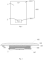
- the present disclosure provides in some embodiments of a display screen, which includes an OLED display screen 1 and an optical fingerprint module 2 arranged in the OLED display screen 1.
- the OLED display screen 1 may include a light-emitting layer 101 and a touch screen.
- the light-emitting layer may include a first light-emitting region 1011 and a second light-emitting region 1012.
- the first light-emitting region 1011 may be arranged at a position corresponding to the optical fingerprint module 2 and configured to emit light at a first preset brightness value, when the region of the touch screen, which corresponds to the first light-emitting region, is not touched.
- the first light-emitting region 1011 emits light at a second preset brightness value.
- the first preset brightness value is smaller than the second preset brightness value.
- the OLED display screen 1 may include the light-emitting layer 101 and the touch screen 102.
- An area about a cross section of the light-emitting layer 101 may equal to, or slightly greater than, an area about a cross section of the touch screen 102, so as to ensure each portion of the touch screen 102 can be irradiated by the light from the light-emitting layer.
- Each portion of the light-emitting layer 101 may emit light at a same brightness value, or emit light at brightness values having a difference within a certain range, so as to provide the light of the touch screen with a homogeneous brightness value as viewed by user's eyes.
- the difference among the brightness values may be within 0.00001 to 0.000001 cd/m 2 .
- cd/m 2 is a luminance unit.
- the first light-emitting region 1011 and the second light-emitting region 1012 may have been designed just at the beginning of the design of the display screen.
- the touch screen may be pressed by a body part of the user having skin patterns, such as a finger. It should be noted that, the touch screen 102 may be pressed by the user's finger, because the optical fingerprint module 2 in the OLED display screen 1 is specially used to identify the fingerprint.
- Two separate circuits may be provided to supply power to the first light-emitting region 1011 and the second light-emitting region 1012, respectively.
- the power may be supplied to the first light-emitting region 1011 through two electric wires, i.e., a first electric wire and a second electric wire.
- the first electric wire is configured to provide an Emissive Layer Voltage Device Device (ELVDD) to the first light-emitting region
- the second electric wire is configured to provide an Emissive Layer Voltage Series Series (ELVSS) to the first light-emitting region 1011.
- the power may be supplied to the second light-emitting region 1012 through two electric wires, i.e., a third electric wire and a fourth electric wire.
- the third electric wire is configured to supply the ELVDD to the second light-emitting region the 1012
- the fourth electric wire is configured to supply ELVSS to the second light-emitting region 1012.
- the first electric wire and the third electric wire may each provide a voltage of 4.6V
- the second electric wire and the fourth electric wire may each provide a voltage of 2.6V.
- the first light-emitting region 1011 and the second light-emitting region 1012 may each emit the light at 430 cd/m 2 , i.e., the first preset brightness value.
- the first electric wire When the touch screen 102 is touched, the first electric wire may provide a voltage of 5.5V and the second electric wire may provide a voltage of 3.0V, so as to enable the first light-emitting region 1011 to emit the light at 600 cd/m 2 , i.e., the second preset brightness value.
- the optical fingerprint module 2 it is able to increase the brightness value of the first light-emitting region 1011 when the touch screen 102 is touched, and enable the optical fingerprint module 2 to identify the skin patterns, e.g., the fingerprint improves a fingerprint identification success rate of the display screen in a more accurate manner.
- Different voltages may be provided when a processor of a mobile terminal is reading information at different regions of the touch screen 102.
- an ELVDD of 4.6V and an ELVSS of 2.8V may be provided when the processor is reading information on the touch screen 102 at a position corresponding to the second light-emitting region 1012
- an ELVDD of 5.5V and an ELVSS of 3.0V may be provided when the processor is reading information on the touch screen 102 at a position corresponding to the first light-emitting region 1011.
- the optical fingerprint module 2 it is also able to increase the brightness value of the first light-emitting region 1011, and enable the optical fingerprint module 2 to identify the skin patterns, e.g., the fingerprint, in a more accurate manner, thereby to improve the fingerprint identification success rate of the display screen.
- the OLED display screen 1 may include the touch screen 102, a transparent adhesive layer 103, a polarizer 104, an upper glass substrate 105, the light-emitting layer 101, a lower glass substrate 106, and a protection foam layer 107.
- the polarizer 104 is attached to the touch screen 102 by the transparent adhesive layer 103.
- the polarizer 104 is configured to change a transmission direction of the light, so as to increase a transmittance and decrease a reflectance. Thereby, the entire display screen presents better display effects.
- the light-emitting layer 101 may be arranged between the upper glass substrate 105 and the lower glass substrate 106, in order to facilitate the transmission of the light from the light-emitting layer 101.
- the protection foam layer 107 is configured to protect the optical fingerprint module 2.
- the optical fingerprint module 2 may be arranged at a same layer as, or arranged below, the protection foam layer 107, so as to be protected by the protection foam layer.
- the display screen may include the display screen and the optical fingerprint module arranged in the OLED display screen.
- the OLED display screen may include the light-emitting layer and the touch screen.
- the light-emitting layer may include the first light-emitting region and the second light-emitting region.
- the first light-emitting region may be arranged at a position corresponding to the optical fingerprint module and configured to, emit light at a first preset brightness value, when the region of the touch screen, which corresponds to the first light-emitting region, is not touched.
- the first light-emitting region When the region of the touch screen, which corresponds to the first light-emitting region, is touched, the first light-emitting region emits light at a second preset brightness value, which is larger than the first preset brightness value.
- the brightness value of the first light-emitting region may be changed from the first preset brightness value to the second preset brightness value. As a result, it is able to increase the brightness value of the first light-emitting region. Furthermore, there is an improvement of the fingerprint identification success rate of the display screen.
- the range of a screen-to-body ratio of the OLED display screen 1 is 85% to 93%.
- the first light-emitting region 1011 When the screen-to-body ratio of the OLED display screen 1 is 85% or 93%, it is able for the first light-emitting region 1011 to emit light at the first preset brightness value when the region of the touch screen 102, which corresponds to the first light-emitting region 1011, is not touched. And the first light-emitting region 1011 emits light at the second preset brightness value when the region of the touch screen 102, which corresponds to the first light-emitting region 1011, is touched.
- the first light-emitting region may emit light at the first preset brightness value when the region of the touch screen 102, which corresponds to the first light-emitting region 1011, is not touched. And the first light-emitting region emits light at the second preset brightness value when the region of the touch screen 102, which corresponds to the first light-emitting region 1011, is touched.
- the OLED display screen having the screen-to-body ratio of 85% to 93% to improve the above effect more obviously.
- the second light-emitting region 1012 is configured to emit light at the first predetermined brightness value, both when the region of the touch screen 102, which corresponds to the first light-emitting region 1011, is not touched, and when the region of the touch screen 102, which corresponds to the first light-emitting region 1011, is touched.
- the second light-emitting region is configured to emit light at the first preset brightness value all the time, so as to ensure that the region of the touch screen, which corresponds to the second light-emitting region 1011, has a constant brightness value.
- a configuration can facilitate the reading of the information on the touch screen at the position corresponding to the second light-emitting region, and prolongs a service life of the display screen.
- the first preset brightness value may be greater than or equal to 600 cd/m 2 .
- the first preset brightness value is greater than or equal to 600 cd/m 2 , it is able to further improve the fingerprint identification success rate of the optical fingerprint module, and also improve the fingerprint identification success rate of the display screen.
- the second preset brightness value may be 0.2 to 430 cd/m 2 .
- the second preset brightness value is 0.2 to 430 cd/m 2 , it is able to prolong the service life of the display screen and promote the controllability of the display screen.
- the optical fingerprint module 2 may be arranged in the OLED display screen 1 through an adhesive.
- the optical fingerprint module when the optical fingerprint module is arranged in the OLED display screen through the adhesive, it is able to fix the optical fingerprint module in a better manner. In addition, when a fault occurs for the optical fingerprint module, it is able to facilitate the disassembly of the optical fingerprint module, thereby to facilitate the maintenance of the display screen.
- the present disclosure further provides in some embodiments of a mobile terminal including the above-mentioned display screen.
- the mobile terminal may be a mobile phone, a tablet personal computer, a laptop computer, a Personal Digital Assistant (PDA), a Mobile Internet Device (MID), or a wearable device.
- PDA Personal Digital Assistant
- MID Mobile Internet Device
- the brightness value of the first light-emitting region may be changed from the first preset brightness value to the second preset brightness value.
- it is able to not only increase the brightness value of the first light-emitting region, but also improve the fingerprint identification success rate of the display screen.
- the present disclosure further provides in some embodiments a display method for the above-mentioned mobile terminal, which includes Step 301 of, when it is detected that the touch screen is touched and skin patterns on the touch screen have been detected by the optical fingerprint module, controlling the first light-emitting region to emit light at the second preset brightness value.
- the first light-emitting region when it is detected that the touch screen is touched and the skin patterns on the touch screen have been detected by the optical fingerprint module, the first light-emitting region may be controlled to emit light at the second predeset brightness value.
- the first light-emitting region emits light at the second preset brightness value, it is able to improve the fingerprint identification success rate of the optical fingerprint module.
- the display method may further include controlling the second light-emitting region to emit light at the first predetermined brightness value.
- the second light-emitting region may be controlled to emit light at the first preset brightness value when the first light-emitting region is controlled to emit light at the second preset brightness value, so as to enable the entire display screen to display at the constant brightness values, which improves the user experience.
- it is able to prevent the second light-emitting region from emitting light at the second preset brightness value, thereby to reduce the power consumption for the entire display screen.
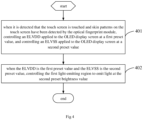
- the present disclosure further provides in some embodiments a display method for the above-mentioned mobile terminal, which includes: Step 401 of, when it is detected that the touch screen is touched and skin patterns on the touch screen have been detected by the optical fingerprint module, controlling an ELVDD applied to the OLED display screen at a first preset value, and controlling an ELVSS applied to the OLED display screen at a second preset value; and Step 402 of, when the ELVDD is the first preset value and the ELVSS is the second preset value, controlling the first light-emitting region to emit light at the second preset brightness value.
- the ELVDD applied to the entire OLED display screen may be controlled to be smaller than a first threshold, and the ELVSS may be controlled to be smaller than a second threshold.
- the first threshold may be smaller than the first preset value
- the second threshold may be smaller than the second preset value.
- the first light-emitting region may be controlled to emit light at the second preset brightness value.
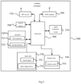
- a mobile terminal 500 which includes a Radio Frequency (RF) circuit 510, a memory 520, an input unit 530, a display unit 540, a processor 560, an audio frequency circuit 570, a Wireless Fidelity (WiFi) module 580 and a power source 590.
- RF Radio Frequency
- the input unit 530 is configured to receive digital or character information inputted by the user, and generate a signal input related to user settings and function control of the mobile terminal 500.
- the input unit 530 may include a touch panel 531.
- the touch panel 531 also called as touch screen, is configured to collect a touch operation made by the user on or in proximity to the touch screen (e.g., an operation made by the user through any appropriate object or attachment (e.g., finger or stylus) on or in the proximity to the touch panel 531), and drive a corresponding connection device in accordance with a predetermined program.
- the touch panel 531 may include a touch detection unit and a touch controller.
- the touch detection unit is configured to detect a touch position and a signal generated due to the touch operation, and transmit the signal to the touch controller.
- the touch controller is configured to receive touch information from the touch detection unit, convert it into coordinates of a touch point, transmit the coordinates to the processor 560, and receive and execute a command from the processor 560.
- the touch panel 531 may be of a resistive type, a capacitive type, an infrared type or a surface acoustic wave (SAW) type.
- the input unit 530 may further include an input device 532 which includes, but not limited to, a physical keyboard, a functional button (e.g., a volume control button or an on/off button), a trackball, a mouse, and a joystick.
- the display unit 540 is configured to display information inputted by the user or information to be presented to the user, and various interfaces for the mobile terminal 500, and it may include a display panel 541.
- the display screen 1441 may be a Liquid Crystal Display (LCD) screen or an OLED screen.
- the touch panel 531 may cover the display panel 541, so as to form a touch display screen.
- the touch information may be transmitted to the processor 560 so as to determine a type of a touch event.
- the processor 560 may provide corresponding visual output on the touch display screen in accordance with the type of the touch event.
- the touch display screen may include an application interface display region and a commonly-used controls display region.
- An arrangement mode of the two display regions will not be particularly defined herein, e.g., one of the two display regions may be arranged above or under the other, or arranged to the left or the right of the other.
- the application interface display region may be adopted to display interfaces for applications, and each interface may include an icon for at least one application and/or an interface element such as Widget desktop control.
- the application interface display region may also be a blank interface where no content is contained.
- the commonly-used controls display region may be adopted to display controls which are used frequently, e.g., setting button, interface number, scroll bar, or such application icons as telephone book icon.
- the processor 560 may be a control center of the mobile terminal 500, and connected to each member of the entire mobile terminal via various interfaces and lines.
- the processor 560 is configured to run or execute software programs and/or modules stored in a first memory 521, and call data stored in a second memory 522, so as to achieve various functions of the mobile terminal 500 and process the data, thereby to monitor the mobile terminal 500.
- the processor 560 may include one or more processing units.
- the mobile terminal 500 may include a display screen, and the display screen may include an OLED display screen and an optical fingerprint module arranged in the OLED display screen.
- the display screen may include a light-emitting layer and a touch screen.
- the processor 560 is configured to, when it is detected that the touch screen is touched and skin lines on the touch screen have been detected by the optical fingerprint module, control the first light-emitting region to emit light at the second predetermined brightness value.
- the processor 560 is further configured to: when it is detected that the touch screen is touched and the skin patterns on the touch screen has been detected by the optical fingerprint module, control an ELVDD applied to the OLED display screen to be a first preset value, and control an ELVSS applied to the OLED display screen to be a second preset value; and when the ELVDD is the first preset value and the ELVSS is the second preset value, control the first light-emitting region to emit light at the second preset brightness value.
- the first light-emitting region may be controlled to emit light at the second preset brightness value. As a result, it is able to achieve functions of the display screen in a better manner, and prolong the service life of the entire display screen.
- the present disclosure further provides in some embodiments a computer-readable storage medium storing therein a computer program.
- the computer program is executed by a processor so as to, when it is detected that the touch screen is touched and skin lines on the touch screen have been detected by the optical fingerprint module, control the first light-emitting region to emit light at the second predetermined brightness value.
- the units may be, or may not be, physically separated from each other.
- the units for displaying may be, or may not be, physical units, i.e., they may be arranged at an identical position, or distributed on a plurality of network elements. Parts or all of the units may be selected in accordance with the practical need, so as to achieve the purpose of the present disclosure.
- the functional units in the embodiments of the present disclosure may be integrated into a processing unit, or the functional units may exist independently, or two or more functional units may be combined together.
- the functional units are implemented in a software form and sold or used as a separate product, they may be stored in a computer-readable medium.
- the technical solutions of the present disclosure partial or full, or parts of the technical solutions of the present disclosure contributing to the related art, may appear in the form of software products, which may be stored in a storage medium and include several instructions so as to enable computer equipment (a personal computer, a server or network equipment) to execute all or parts of the steps of the method according to the embodiments of the present disclosure.
- the storage medium includes any medium capable of storing therein program codes, e.g., a universal serial bus (USB) flash disk, a mobile hard disk (HD), a read-only memory (ROM), a random access memory (RAM), a magnetic disk or an optical disk.
- program codes e.g., a universal serial bus (USB) flash disk, a mobile hard disk (HD), a read-only memory (ROM), a random access memory (RAM), a magnetic disk or an optical disk.
- the computer program may be stored in a computer-readable storage medium.
- the storage medium may be a magnetic disc, an optical disc, an ROM or an RAM.
Landscapes
- Engineering & Computer Science (AREA)
- Theoretical Computer Science (AREA)
- Human Computer Interaction (AREA)
- Physics & Mathematics (AREA)
- General Physics & Mathematics (AREA)
- General Engineering & Computer Science (AREA)
- Multimedia (AREA)
- Signal Processing (AREA)
- Electroluminescent Light Sources (AREA)
- User Interface Of Digital Computer (AREA)
- Devices For Indicating Variable Information By Combining Individual Elements (AREA)
Claims (11)
- Anzeigebildschirm (1), umfassend einen organischen Leuchtdiode, OLED, -Anzeigebildschirm und ein optisches Fingerabdruckmodul (2), das in dem OLED-Anzeigebildschirm (1) angeordnet ist, wobei der OLED-Anzeigebildschirm (1) eine lichtemittierende Schicht (101) und einen Berührungsbildschirm (102) umfasst, die lichtemittierende Schicht (101) einen ersten lichtemittierenden Bereich (1011) und einen zweiten lichtemittierenden Bereich (1012) umfasst, und der erste lichtemittierende Bereich (1011) an einer Position angeordnet ist, die dem optischen Fingerabdruckmodul (2) entspricht, und ausgelegt ist, um, wenn der Bereich des Berührungsbildschirms (102), der dem ersten lichtemittierenden Bereich (1011) entspricht, nicht berührt wird, Licht mit einem ersten voreingestellten Helligkeitswert zu emittieren, und wenn der Bereich des Berührungsbildschirms (102), der dem ersten lichtemittierenden Bereich (1011) entspricht, berührt wird, Licht mit einem zweiten voreingestellten Helligkeitswert zu emittieren, der erste voreingestellte Helligkeitswert kleiner als der zweite voreingestellte Helligkeitswert ist,
dadurch gekennzeichnet, dass
zwei getrennte Schaltungen bereitgestellt sind, um den ersten lichtemittierende Bereich (1011) und den zweiten lichtemittierenden Bereich (1012) mit Leistung zu versorgen. - Anzeigebildschirm (1) nach Anspruch 1, wobei der zweite lichtemittierende Bereich (1012) ausgelegt ist, um, wenn der Bereich des Berührungsbildschirms (102), der dem ersten lichtemittierenden Bereich (1011) entspricht, nicht berührt wird, und wenn der Bereich des Berührungsbildschirms (102), der dem ersten lichtemittierenden Bereich (1011) entspricht, berührt wird, Licht mit dem ersten voreingestellten Helligkeitswert zu emittieren.
- Anzeigebildschirm (1) nach Anspruch 2, wobei der erste voreingestellte Helligkeitswert 0,2 bis 430 cd/m2 beträgt.
- Anzeigebildschirm (1) nach Anspruch 3, wobei der zweite voreingestellte Helligkeitswert größer oder gleich 600 cd/m2 ist.
- Anzeigebildschirm (1) nach Anspruch 4, wobei das optische Fingerabdruckmodul (2) in dem OLED-Anzeigebildschirm durch einen Kleber angeordnet ist.
- Mobiles Endgerät, umfassend den Anzeigebildschirm nach einem der Ansprüche 1-5.
- Anzeigeverfahren für das mobile Endgerät nach Anspruch 6, umfassend:
Steuern, wenn erkannt wird, dass der Berührungsbildschirm (102) berührt wird und Hautmuster auf dem Berührungsbildschirm (102) durch das optische Fingerabdruckmodul (2) erkannt wurden, des ersten lichtemittierenden Bereichs (1011), um Licht mit dem zweiten voreingestellten Helligkeitswert zu emittieren. - Anzeigeverfahren nach Anspruch 7, wobei das Steuern, wenn erkannt wird, dass der Berührungsbildschirm (102) berührt wird und die Hautmuster auf dem Berührungsbildschirm (102) durch das optische Fingerabdruckmodul (2) erkannt wurden, des ersten lichtemittierenden Bereichs (1011), um Licht mit dem zweiten voreingestellten Helligkeitswert zu emittieren, Folgendes umfasst:Steuern, wenn erkannt wird, dass der Berührungsbildschirm (102) berührt wird und die Hautmuster auf dem Berührungsbildschirm (102) durch das optische Fingerabdruckmodul (2) erkannt wurden, einer Emissive Layer Voltage Device Device, ELVDD, die auf den OLED-Anzeigebildschirm angewendet wird, um ein erster voreingestellter Wert zu sein, und einer Emissive Layer Voltage Series Series, ELVSS, die auf den OLED-Anzeigebildschirm angewendet wird, um ein zweiter voreingestellter Wert zu sein; undSteuern, wenn die ELVDD der erste voreingestellte Wert ist und der ELVSS der zweite voreingestellte Wert ist, des ersten lichtemittierenden Bereichs (1011), um Licht mit dem zweiten voreingestellten Helligkeitswert zu emittieren.
- Anzeigeverfahren nach Anspruch 7 oder 8, wobei das Anzeigeverfahren nach dem Steuern des ersten lichtemittierenden Bereichs (1011) zum Emittieren von Licht mit dem zweiten voreingestellten Helligkeitswert ferner Folgendes umfasst:
Steuern des zweiten lichtemittierenden Bereichs (1012), um Licht mit dem ersten voreingestellten Helligkeitswert zu emittieren. - Mobiles Endgerät, umfassend einen Speicher, einen Prozessor und ein Computerprogramm, das in dem Speicher gespeichert und durch den Prozessor ausgeführt wird, wobei der Prozessor dazu ausgelegt ist, das Computerprogramm auszuführen, um das Anzeigeverfahren nach einem der Ansprüche 7-9 zu implementieren.
- Computerlesbares Speichermedium, das darin ein Computerprogramm speichert, wobei das Computerprogramm durch einen Prozessor ausgeführt wird, um die Schritte des Anzeigeverfahrens nach einem der Ansprüche 7-9 zu implementieren.
Applications Claiming Priority (2)
| Application Number | Priority Date | Filing Date | Title |
|---|---|---|---|
| CN201710895986.7A CN107819011B (zh) | 2017-09-28 | 2017-09-28 | 一种显示屏、移动终端和显示方法 |
| PCT/CN2018/103564 WO2019062471A1 (zh) | 2017-09-28 | 2018-08-31 | 显示屏、移动终端和显示方法 |
Publications (3)
| Publication Number | Publication Date |
|---|---|
| EP3690948A1 EP3690948A1 (de) | 2020-08-05 |
| EP3690948A4 EP3690948A4 (de) | 2020-11-18 |
| EP3690948B1 true EP3690948B1 (de) | 2025-04-23 |
Family
ID=61607174
Family Applications (1)
| Application Number | Title | Priority Date | Filing Date |
|---|---|---|---|
| EP18863610.4A Active EP3690948B1 (de) | 2017-09-28 | 2018-08-31 | Anzeigebildschirm, mobiles endgerät und anzeigeverfahren |
Country Status (5)
| Country | Link |
|---|---|
| US (1) | US11145695B2 (de) |
| EP (1) | EP3690948B1 (de) |
| CN (1) | CN107819011B (de) |
| ES (1) | ES3025786T3 (de) |
| WO (1) | WO2019062471A1 (de) |
Families Citing this family (16)
| Publication number | Priority date | Publication date | Assignee | Title |
|---|---|---|---|---|
| CN107819011B (zh) * | 2017-09-28 | 2019-12-17 | 维沃移动通信有限公司 | 一种显示屏、移动终端和显示方法 |
| CN108762379A (zh) * | 2018-04-10 | 2018-11-06 | 珠海市魅族科技有限公司 | 显示方法及装置、计算机装置和计算机可读存储介质 |
| CN108648691B (zh) | 2018-05-14 | 2020-03-20 | 上海天马有机发光显示技术有限公司 | 显示面板及其驱动方法、显示装置 |
| CN108399890B (zh) * | 2018-05-30 | 2020-08-18 | 上海天马有机发光显示技术有限公司 | 一种有机发光显示面板及其驱动方法、有机发光显示装置 |
| CN108776789B (zh) | 2018-06-05 | 2020-12-04 | 上海天马有机发光显示技术有限公司 | 显示面板和显示装置 |
| KR102623375B1 (ko) * | 2018-06-08 | 2024-01-11 | 삼성디스플레이 주식회사 | 표시장치 및 이의 제조 방법 |
| CN110658886A (zh) * | 2018-06-29 | 2020-01-07 | 中兴通讯股份有限公司 | 显示屏模组、终端及其控制方法、装置、计算机存储介质 |
| CN109343811B (zh) * | 2018-09-30 | 2022-06-24 | 维沃移动通信有限公司 | 一种显示调整方法及终端设备 |
| CN109545132A (zh) * | 2018-11-26 | 2019-03-29 | 昆山国显光电有限公司 | 屏体显示方法、显示屏及电子设备 |
| CN109445160B (zh) * | 2018-12-27 | 2021-09-28 | 厦门天马微电子有限公司 | 显示模组及显示装置 |
| CN109902626B (zh) * | 2019-02-27 | 2024-01-05 | 维沃移动通信有限公司 | 终端设备 |
| KR102655532B1 (ko) | 2019-05-14 | 2024-04-09 | 삼성전자주식회사 | 디스플레이의 광을 이용하여 생체 정보를 획득하기 위한 전자 장치 및 방법 |
| CN110379351B (zh) * | 2019-07-29 | 2022-10-11 | 武汉天马微电子有限公司 | 显示面板的驱动方法、显示面板及显示装置 |
| CN110519432B (zh) * | 2019-09-09 | 2021-04-09 | Oppo(重庆)智能科技有限公司 | 电子装置 |
| CN111309135B (zh) * | 2020-01-14 | 2021-07-16 | 昆山国显光电有限公司 | 显示屏的感光控制方法及其感光控制装置、显示装置 |
| JP7811991B2 (ja) | 2021-10-18 | 2026-02-06 | グーグル エルエルシー | アンダーディスプレイセンサーのための輝度制御 |
Family Cites Families (18)
| Publication number | Priority date | Publication date | Assignee | Title |
|---|---|---|---|---|
| KR101761636B1 (ko) * | 2010-07-20 | 2017-07-27 | 삼성디스플레이 주식회사 | 유기전계발광 표시장치 |
| US8994690B2 (en) | 2012-04-29 | 2015-03-31 | Weidong Shi | Method and apparatuses of transparent fingerprint imager integrated with touch display device |
| KR101566198B1 (ko) * | 2013-06-28 | 2015-11-05 | 삼성전자주식회사 | 초음파 진단 장치의 디스플레이 이동 방법 및 초음파 진단 장치 |
| KR102288308B1 (ko) * | 2014-08-05 | 2021-08-10 | 삼성메디슨 주식회사 | 초음파 진단 장치 |
| CN107004130B (zh) * | 2015-06-18 | 2020-08-28 | 深圳市汇顶科技股份有限公司 | 用于屏幕上指纹感应的屏幕下光学传感器模块 |
| KR102519423B1 (ko) * | 2015-09-15 | 2023-04-10 | 삼성메디슨 주식회사 | 조영 영상으로부터 정보를 획득하는 방법, 이를 위한 초음파 장치 및 초음파 장치의 동작 방법 |
| CN106570442B (zh) * | 2015-10-09 | 2021-05-14 | 小米科技有限责任公司 | 指纹识别方法及装置 |
| KR20170091438A (ko) * | 2016-02-01 | 2017-08-09 | 삼성메디슨 주식회사 | 초음파 영상 표시 방법 및 장치 |
| CN105912168A (zh) * | 2016-04-22 | 2016-08-31 | 上海与德通讯技术有限公司 | 显示模组、电子设备及指纹解锁方法 |
| CN107346411A (zh) * | 2016-05-06 | 2017-11-14 | 曦威科技股份有限公司 | 光学感测模块及指纹感测装置 |
| KR101816509B1 (ko) * | 2016-08-03 | 2018-02-21 | 주식회사 슈프리마 | 위조 지문 판별 장치 및 그 제작 방법 |
| US20180157395A1 (en) * | 2016-12-07 | 2018-06-07 | Lg Electronics Inc. | Mobile terminal and method for controlling the same |
| CN106778707B (zh) * | 2017-02-09 | 2020-09-11 | Oppo广东移动通信有限公司 | 指纹识别方法、显示屏以及移动终端 |
| KR102040388B1 (ko) * | 2017-04-19 | 2019-11-04 | 선전 구딕스 테크놀로지 컴퍼니, 리미티드 | 광 강도 검출 방법, 장치 및 스마트 단말기 |
| CN107194324A (zh) | 2017-04-28 | 2017-09-22 | 广东欧珀移动通信有限公司 | 指纹识别区域显示方法及相关产品 |
| CN107168469B (zh) | 2017-06-20 | 2020-02-07 | Oppo广东移动通信有限公司 | 指纹的采集方法及相关产品 |
| KR102143148B1 (ko) * | 2017-09-09 | 2020-08-10 | 애플 인크. | 생체측정 인증의 구현 |
| CN107819011B (zh) | 2017-09-28 | 2019-12-17 | 维沃移动通信有限公司 | 一种显示屏、移动终端和显示方法 |
-
2017
- 2017-09-28 CN CN201710895986.7A patent/CN107819011B/zh active Active
-
2018
- 2018-08-31 EP EP18863610.4A patent/EP3690948B1/de active Active
- 2018-08-31 WO PCT/CN2018/103564 patent/WO2019062471A1/zh not_active Ceased
- 2018-08-31 ES ES18863610T patent/ES3025786T3/es active Active
- 2018-08-31 US US16/651,471 patent/US11145695B2/en active Active
Also Published As
| Publication number | Publication date |
|---|---|
| EP3690948A4 (de) | 2020-11-18 |
| WO2019062471A1 (zh) | 2019-04-04 |
| CN107819011A (zh) | 2018-03-20 |
| ES3025786T3 (en) | 2025-06-09 |
| EP3690948A1 (de) | 2020-08-05 |
| CN107819011B (zh) | 2019-12-17 |
| US20200266245A1 (en) | 2020-08-20 |
| US11145695B2 (en) | 2021-10-12 |
Similar Documents
| Publication | Publication Date | Title |
|---|---|---|
| EP3690948B1 (de) | Anzeigebildschirm, mobiles endgerät und anzeigeverfahren | |
| US10684650B2 (en) | Electronic device including module mounted in sunken area of layer | |
| EP3279778B1 (de) | Elektronische vorrichtung mit fingerabdrucksensor | |
| US9904510B2 (en) | Information handling devices with touch-based reflective display | |
| KR102163104B1 (ko) | 시변 특성을 갖는 구동 신호를 사용한 터치 패널 여기 | |
| EP3096210B1 (de) | Verfahren und vorrichtung zur verarbeitung von eingaben unter verwendung einer berührungsanzeige | |
| US9007297B2 (en) | Information handling devices with touch-based reflective display | |
| US11132121B2 (en) | Method, apparatus, storage medium, and electronic device of processing split screen display | |
| US10088968B2 (en) | Touch panel and display device | |
| US12131019B2 (en) | Virtual keyboard animation | |
| US20150309660A1 (en) | Method and device for controlling operation according to damage to touch area of electronic device | |
| US11150749B2 (en) | Control module for stylus with whiteboard-style erasure | |
| US20140240252A1 (en) | Electronic apparatus, method of controlling the same, and computer-readable recording medium | |
| US11244142B2 (en) | Unlocking method and mobile terminal | |
| US20160378231A1 (en) | Display device | |
| US20080055256A1 (en) | Touch screen controller with embedded overlay | |
| US20150160776A1 (en) | Input device, input disabling method, input disabling program, and computer readable recording medium | |
| US10691207B2 (en) | Display devices with virtual reprsentations of electronic devices | |
| KR102353919B1 (ko) | 터치의 압력에 응답하여 지정된 동작을 수행하는 전자 장치 및 방법 | |
| US20240168782A1 (en) | Electronic device, and methods of the electronic device for generating feedback related to an interaction with a touch input arrangement | |
| US20110199309A1 (en) | Input Device | |
| US20100265107A1 (en) | Self-description of an adaptive input device | |
| US10282091B2 (en) | Bi-stable display based off-screen keyboard | |
| EP3313054B1 (de) | System mit einem elektronischen gerät mit zusatzgerät | |
| US20240377906A1 (en) | Sensor Module and Control Method for Sensor Module |
Legal Events
| Date | Code | Title | Description |
|---|---|---|---|
| STAA | Information on the status of an ep patent application or granted ep patent |
Free format text: STATUS: THE INTERNATIONAL PUBLICATION HAS BEEN MADE |
|
| PUAI | Public reference made under article 153(3) epc to a published international application that has entered the european phase |
Free format text: ORIGINAL CODE: 0009012 |
|
| STAA | Information on the status of an ep patent application or granted ep patent |
Free format text: STATUS: REQUEST FOR EXAMINATION WAS MADE |
|
| 17P | Request for examination filed |
Effective date: 20200302 |
|
| AK | Designated contracting states |
Kind code of ref document: A1 Designated state(s): AL AT BE BG CH CY CZ DE DK EE ES FI FR GB GR HR HU IE IS IT LI LT LU LV MC MK MT NL NO PL PT RO RS SE SI SK SM TR |
|
| AX | Request for extension of the european patent |
Extension state: BA ME |
|
| A4 | Supplementary search report drawn up and despatched |
Effective date: 20201021 |
|
| RIC1 | Information provided on ipc code assigned before grant |
Ipc: G06F 3/042 20060101AFI20201015BHEP Ipc: G06K 9/00 20060101ALI20201015BHEP |
|
| RIN1 | Information on inventor provided before grant (corrected) |
Inventor name: DENG, ZIQIANG |
|
| DAV | Request for validation of the european patent (deleted) | ||
| DAX | Request for extension of the european patent (deleted) | ||
| STAA | Information on the status of an ep patent application or granted ep patent |
Free format text: STATUS: EXAMINATION IS IN PROGRESS |
|
| 17Q | First examination report despatched |
Effective date: 20221110 |
|
| REG | Reference to a national code |
Ref country code: DE Free format text: PREVIOUS MAIN CLASS: H01L0027320000 Ref country code: DE Ref legal event code: R079 Ref document number: 602018081393 Country of ref document: DE Free format text: PREVIOUS MAIN CLASS: H01L0027320000 Ipc: G06F0003042000 |
|
| GRAP | Despatch of communication of intention to grant a patent |
Free format text: ORIGINAL CODE: EPIDOSNIGR1 |
|
| STAA | Information on the status of an ep patent application or granted ep patent |
Free format text: STATUS: GRANT OF PATENT IS INTENDED |
|
| RIC1 | Information provided on ipc code assigned before grant |
Ipc: G06V 40/13 20220101ALI20241213BHEP Ipc: G06F 3/042 20060101AFI20241213BHEP |
|
| INTG | Intention to grant announced |
Effective date: 20250103 |
|
| GRAS | Grant fee paid |
Free format text: ORIGINAL CODE: EPIDOSNIGR3 |
|
| GRAA | (expected) grant |
Free format text: ORIGINAL CODE: 0009210 |
|
| STAA | Information on the status of an ep patent application or granted ep patent |
Free format text: STATUS: THE PATENT HAS BEEN GRANTED |
|
| AK | Designated contracting states |
Kind code of ref document: B1 Designated state(s): AL AT BE BG CH CY CZ DE DK EE ES FI FR GB GR HR HU IE IS IT LI LT LU LV MC MK MT NL NO PL PT RO RS SE SI SK SM TR |
|
| REG | Reference to a national code |
Ref country code: GB Ref legal event code: FG4D |
|
| REG | Reference to a national code |
Ref country code: CH Ref legal event code: EP |
|
| REG | Reference to a national code |
Ref country code: DE Ref legal event code: R096 Ref document number: 602018081393 Country of ref document: DE |
|
| REG | Reference to a national code |
Ref country code: IE Ref legal event code: FG4D |
|
| REG | Reference to a national code |
Ref country code: NL Ref legal event code: FP |
|
| REG | Reference to a national code |
Ref country code: ES Ref legal event code: FG2A Ref document number: 3025786 Country of ref document: ES Kind code of ref document: T3 Effective date: 20250609 |
|
| PGFP | Annual fee paid to national office [announced via postgrant information from national office to epo] |
Ref country code: NL Payment date: 20250704 Year of fee payment: 8 |
|
| REG | Reference to a national code |
Ref country code: AT Ref legal event code: MK05 Ref document number: 1788406 Country of ref document: AT Kind code of ref document: T Effective date: 20250423 |
|
| REG | Reference to a national code |
Ref country code: CH Ref legal event code: U11 Free format text: ST27 STATUS EVENT CODE: U-0-0-U10-U11 (AS PROVIDED BY THE NATIONAL OFFICE) Effective date: 20251006 |
|
| PG25 | Lapsed in a contracting state [announced via postgrant information from national office to epo] |
Ref country code: PT Free format text: LAPSE BECAUSE OF FAILURE TO SUBMIT A TRANSLATION OF THE DESCRIPTION OR TO PAY THE FEE WITHIN THE PRESCRIBED TIME-LIMIT Effective date: 20250825 Ref country code: FI Free format text: LAPSE BECAUSE OF FAILURE TO SUBMIT A TRANSLATION OF THE DESCRIPTION OR TO PAY THE FEE WITHIN THE PRESCRIBED TIME-LIMIT Effective date: 20250423 |
|
| PGFP | Annual fee paid to national office [announced via postgrant information from national office to epo] |
Ref country code: ES Payment date: 20250909 Year of fee payment: 8 |
|
| PGFP | Annual fee paid to national office [announced via postgrant information from national office to epo] |
Ref country code: DE Payment date: 20250702 Year of fee payment: 8 |
|
| REG | Reference to a national code |
Ref country code: LT Ref legal event code: MG9D |
|
| PG25 | Lapsed in a contracting state [announced via postgrant information from national office to epo] |
Ref country code: GR Free format text: LAPSE BECAUSE OF FAILURE TO SUBMIT A TRANSLATION OF THE DESCRIPTION OR TO PAY THE FEE WITHIN THE PRESCRIBED TIME-LIMIT Effective date: 20250724 Ref country code: NO Free format text: LAPSE BECAUSE OF FAILURE TO SUBMIT A TRANSLATION OF THE DESCRIPTION OR TO PAY THE FEE WITHIN THE PRESCRIBED TIME-LIMIT Effective date: 20250723 |
|
| PG25 | Lapsed in a contracting state [announced via postgrant information from national office to epo] |
Ref country code: PL Free format text: LAPSE BECAUSE OF FAILURE TO SUBMIT A TRANSLATION OF THE DESCRIPTION OR TO PAY THE FEE WITHIN THE PRESCRIBED TIME-LIMIT Effective date: 20250423 |
|
| PGFP | Annual fee paid to national office [announced via postgrant information from national office to epo] |
Ref country code: IT Payment date: 20250722 Year of fee payment: 8 |
|
| PG25 | Lapsed in a contracting state [announced via postgrant information from national office to epo] |
Ref country code: BG Free format text: LAPSE BECAUSE OF FAILURE TO SUBMIT A TRANSLATION OF THE DESCRIPTION OR TO PAY THE FEE WITHIN THE PRESCRIBED TIME-LIMIT Effective date: 20250423 |
|
| PGFP | Annual fee paid to national office [announced via postgrant information from national office to epo] |
Ref country code: GB Payment date: 20250703 Year of fee payment: 8 |
|
| PG25 | Lapsed in a contracting state [announced via postgrant information from national office to epo] |
Ref country code: HR Free format text: LAPSE BECAUSE OF FAILURE TO SUBMIT A TRANSLATION OF THE DESCRIPTION OR TO PAY THE FEE WITHIN THE PRESCRIBED TIME-LIMIT Effective date: 20250423 |
|
| PG25 | Lapsed in a contracting state [announced via postgrant information from national office to epo] |
Ref country code: AT Free format text: LAPSE BECAUSE OF FAILURE TO SUBMIT A TRANSLATION OF THE DESCRIPTION OR TO PAY THE FEE WITHIN THE PRESCRIBED TIME-LIMIT Effective date: 20250423 |
|
| PGFP | Annual fee paid to national office [announced via postgrant information from national office to epo] |
Ref country code: FR Payment date: 20250703 Year of fee payment: 8 |
|
| PGFP | Annual fee paid to national office [announced via postgrant information from national office to epo] |
Ref country code: MT Payment date: 20250926 Year of fee payment: 8 |
|
| PG25 | Lapsed in a contracting state [announced via postgrant information from national office to epo] |
Ref country code: RS Free format text: LAPSE BECAUSE OF FAILURE TO SUBMIT A TRANSLATION OF THE DESCRIPTION OR TO PAY THE FEE WITHIN THE PRESCRIBED TIME-LIMIT Effective date: 20250723 |
|
| PG25 | Lapsed in a contracting state [announced via postgrant information from national office to epo] |
Ref country code: IS Free format text: LAPSE BECAUSE OF FAILURE TO SUBMIT A TRANSLATION OF THE DESCRIPTION OR TO PAY THE FEE WITHIN THE PRESCRIBED TIME-LIMIT Effective date: 20250823 |
|
| PG25 | Lapsed in a contracting state [announced via postgrant information from national office to epo] |
Ref country code: LV Free format text: LAPSE BECAUSE OF FAILURE TO SUBMIT A TRANSLATION OF THE DESCRIPTION OR TO PAY THE FEE WITHIN THE PRESCRIBED TIME-LIMIT Effective date: 20250423 |
|
| PGFP | Annual fee paid to national office [announced via postgrant information from national office to epo] |
Ref country code: LU Payment date: 20251016 Year of fee payment: 8 |
|
| PGFP | Annual fee paid to national office [announced via postgrant information from national office to epo] |
Ref country code: MC Payment date: 20251002 Year of fee payment: 8 |
|
| PG25 | Lapsed in a contracting state [announced via postgrant information from national office to epo] |
Ref country code: SM Free format text: LAPSE BECAUSE OF FAILURE TO SUBMIT A TRANSLATION OF THE DESCRIPTION OR TO PAY THE FEE WITHIN THE PRESCRIBED TIME-LIMIT Effective date: 20250423 Ref country code: DK Free format text: LAPSE BECAUSE OF FAILURE TO SUBMIT A TRANSLATION OF THE DESCRIPTION OR TO PAY THE FEE WITHIN THE PRESCRIBED TIME-LIMIT Effective date: 20250423 |
|
| PGFP | Annual fee paid to national office [announced via postgrant information from national office to epo] |
Ref country code: BE Payment date: 20251006 Year of fee payment: 8 |
|
| PGFP | Annual fee paid to national office [announced via postgrant information from national office to epo] |
Ref country code: CH Payment date: 20251006 Year of fee payment: 8 |
|
| PG25 | Lapsed in a contracting state [announced via postgrant information from national office to epo] |
Ref country code: CZ Free format text: LAPSE BECAUSE OF FAILURE TO SUBMIT A TRANSLATION OF THE DESCRIPTION OR TO PAY THE FEE WITHIN THE PRESCRIBED TIME-LIMIT Effective date: 20250423 |
|
| PGFP | Annual fee paid to national office [announced via postgrant information from national office to epo] |
Ref country code: IE Payment date: 20251001 Year of fee payment: 8 |
|
| PG25 | Lapsed in a contracting state [announced via postgrant information from national office to epo] |
Ref country code: EE Free format text: LAPSE BECAUSE OF FAILURE TO SUBMIT A TRANSLATION OF THE DESCRIPTION OR TO PAY THE FEE WITHIN THE PRESCRIBED TIME-LIMIT Effective date: 20250423 |
|
| REG | Reference to a national code |
Ref country code: DE Ref legal event code: R097 Ref document number: 602018081393 Country of ref document: DE |
|
| PG25 | Lapsed in a contracting state [announced via postgrant information from national office to epo] |
Ref country code: SK Free format text: LAPSE BECAUSE OF FAILURE TO SUBMIT A TRANSLATION OF THE DESCRIPTION OR TO PAY THE FEE WITHIN THE PRESCRIBED TIME-LIMIT Effective date: 20250423 Ref country code: RO Free format text: LAPSE BECAUSE OF FAILURE TO SUBMIT A TRANSLATION OF THE DESCRIPTION OR TO PAY THE FEE WITHIN THE PRESCRIBED TIME-LIMIT Effective date: 20250423 |
|
| PLBE | No opposition filed within time limit |
Free format text: ORIGINAL CODE: 0009261 |
|
| STAA | Information on the status of an ep patent application or granted ep patent |
Free format text: STATUS: NO OPPOSITION FILED WITHIN TIME LIMIT |
|
| REG | Reference to a national code |
Ref country code: CH Ref legal event code: L10 Free format text: ST27 STATUS EVENT CODE: U-0-0-L10-L00 (AS PROVIDED BY THE NATIONAL OFFICE) Effective date: 20260304 |
|
| 26N | No opposition filed |
Effective date: 20260126 |