EP3690600B1 - Faltbare anzeige mit steifer stütze - Google Patents
Faltbare anzeige mit steifer stütze Download PDFInfo
- Publication number
- EP3690600B1 EP3690600B1 EP20154440.0A EP20154440A EP3690600B1 EP 3690600 B1 EP3690600 B1 EP 3690600B1 EP 20154440 A EP20154440 A EP 20154440A EP 3690600 B1 EP3690600 B1 EP 3690600B1
- Authority
- EP
- European Patent Office
- Prior art keywords
- layer
- stiff support
- display
- support sub
- sub
- Prior art date
- Legal status (The legal status is an assumption and is not a legal conclusion. Google has not performed a legal analysis and makes no representation as to the accuracy of the status listed.)
- Active
Links
Images




Classifications
-
- G—PHYSICS
- G06—COMPUTING OR CALCULATING; COUNTING
- G06F—ELECTRIC DIGITAL DATA PROCESSING
- G06F1/00—Details not covered by groups G06F3/00 - G06F13/00 and G06F21/00
- G06F1/16—Constructional details or arrangements
- G06F1/1613—Constructional details or arrangements for portable computers
- G06F1/1633—Constructional details or arrangements of portable computers not specific to the type of enclosures covered by groups G06F1/1615 - G06F1/1626
- G06F1/1637—Details related to the display arrangement, including those related to the mounting of the display in the housing
- G06F1/1652—Details related to the display arrangement, including those related to the mounting of the display in the housing the display being flexible, e.g. mimicking a sheet of paper, or rollable
-
- G—PHYSICS
- G09—EDUCATION; CRYPTOGRAPHY; DISPLAY; ADVERTISING; SEALS
- G09F—DISPLAYING; ADVERTISING; SIGNS; LABELS OR NAME-PLATES; SEALS
- G09F9/00—Indicating arrangements for variable information in which the information is built-up on a support by selection or combination of individual elements
- G09F9/30—Indicating arrangements for variable information in which the information is built-up on a support by selection or combination of individual elements in which the desired character or characters are formed by combining individual elements
- G09F9/301—Indicating arrangements for variable information in which the information is built-up on a support by selection or combination of individual elements in which the desired character or characters are formed by combining individual elements flexible foldable or roll-able electronic displays, e.g. thin LCD, OLED
-
- B—PERFORMING OPERATIONS; TRANSPORTING
- B32—LAYERED PRODUCTS
- B32B—LAYERED PRODUCTS, i.e. PRODUCTS BUILT-UP OF STRATA OF FLAT OR NON-FLAT, e.g. CELLULAR OR HONEYCOMB, FORM
- B32B37/00—Methods or apparatus for laminating, e.g. by curing or by ultrasonic bonding
- B32B37/12—Methods or apparatus for laminating, e.g. by curing or by ultrasonic bonding characterised by using adhesives
-
- B—PERFORMING OPERATIONS; TRANSPORTING
- B32—LAYERED PRODUCTS
- B32B—LAYERED PRODUCTS, i.e. PRODUCTS BUILT-UP OF STRATA OF FLAT OR NON-FLAT, e.g. CELLULAR OR HONEYCOMB, FORM
- B32B7/00—Layered products characterised by the relation between layers; Layered products characterised by the relative orientation of features between layers, or by the relative values of a measurable parameter between layers, i.e. products comprising layers having different physical, chemical or physicochemical properties; Layered products characterised by the interconnection of layers
- B32B7/04—Interconnection of layers
- B32B7/12—Interconnection of layers using interposed adhesives or interposed materials with bonding properties
-
- G—PHYSICS
- G06—COMPUTING OR CALCULATING; COUNTING
- G06F—ELECTRIC DIGITAL DATA PROCESSING
- G06F1/00—Details not covered by groups G06F3/00 - G06F13/00 and G06F21/00
- G06F1/16—Constructional details or arrangements
- G06F1/1613—Constructional details or arrangements for portable computers
- G06F1/1615—Constructional details or arrangements for portable computers with several enclosures having relative motions, each enclosure supporting at least one I/O or computing function
- G06F1/1616—Constructional details or arrangements for portable computers with several enclosures having relative motions, each enclosure supporting at least one I/O or computing function with folding flat displays, e.g. laptop computers or notebooks having a clamshell configuration, with body parts pivoting to an open position around an axis parallel to the plane they define in closed position
-
- G—PHYSICS
- G06—COMPUTING OR CALCULATING; COUNTING
- G06F—ELECTRIC DIGITAL DATA PROCESSING
- G06F1/00—Details not covered by groups G06F3/00 - G06F13/00 and G06F21/00
- G06F1/16—Constructional details or arrangements
- G06F1/1613—Constructional details or arrangements for portable computers
- G06F1/1615—Constructional details or arrangements for portable computers with several enclosures having relative motions, each enclosure supporting at least one I/O or computing function
- G06F1/1616—Constructional details or arrangements for portable computers with several enclosures having relative motions, each enclosure supporting at least one I/O or computing function with folding flat displays, e.g. laptop computers or notebooks having a clamshell configuration, with body parts pivoting to an open position around an axis parallel to the plane they define in closed position
- G06F1/1618—Constructional details or arrangements for portable computers with several enclosures having relative motions, each enclosure supporting at least one I/O or computing function with folding flat displays, e.g. laptop computers or notebooks having a clamshell configuration, with body parts pivoting to an open position around an axis parallel to the plane they define in closed position the display being foldable up to the back of the other housing with a single degree of freedom, e.g. by 360° rotation over the axis defined by the rear edge of the base enclosure
-
- G—PHYSICS
- G06—COMPUTING OR CALCULATING; COUNTING
- G06F—ELECTRIC DIGITAL DATA PROCESSING
- G06F1/00—Details not covered by groups G06F3/00 - G06F13/00 and G06F21/00
- G06F1/16—Constructional details or arrangements
- G06F1/1613—Constructional details or arrangements for portable computers
- G06F1/1633—Constructional details or arrangements of portable computers not specific to the type of enclosures covered by groups G06F1/1615 - G06F1/1626
- G06F1/1656—Details related to functional adaptations of the enclosure, e.g. to provide protection against EMI, shock, water, or to host detachable peripherals like a mouse or removable expansions units like PCMCIA cards, or to provide access to internal components for maintenance or to removable storage supports like CDs or DVDs, or to mechanically mount accessories
-
- G—PHYSICS
- G06—COMPUTING OR CALCULATING; COUNTING
- G06F—ELECTRIC DIGITAL DATA PROCESSING
- G06F1/00—Details not covered by groups G06F3/00 - G06F13/00 and G06F21/00
- G06F1/16—Constructional details or arrangements
- G06F1/1613—Constructional details or arrangements for portable computers
- G06F1/1633—Constructional details or arrangements of portable computers not specific to the type of enclosures covered by groups G06F1/1615 - G06F1/1626
- G06F1/1675—Miscellaneous details related to the relative movement between the different enclosures or enclosure parts
- G06F1/1681—Details related solely to hinges
-
- H—ELECTRICITY
- H04—ELECTRIC COMMUNICATION TECHNIQUE
- H04M—TELEPHONIC COMMUNICATION
- H04M1/00—Substation equipment, e.g. for use by subscribers
- H04M1/02—Constructional features of telephone sets
- H04M1/0202—Portable telephone sets, e.g. cordless phones, mobile phones or bar type handsets
- H04M1/0206—Portable telephones comprising a plurality of mechanically joined movable body parts, e.g. hinged housings
- H04M1/0208—Portable telephones comprising a plurality of mechanically joined movable body parts, e.g. hinged housings characterized by the relative motions of the body parts
- H04M1/021—Portable telephones comprising a plurality of mechanically joined movable body parts, e.g. hinged housings characterized by the relative motions of the body parts using combined folding and rotation motions
-
- H—ELECTRICITY
- H04—ELECTRIC COMMUNICATION TECHNIQUE
- H04M—TELEPHONIC COMMUNICATION
- H04M1/00—Substation equipment, e.g. for use by subscribers
- H04M1/02—Constructional features of telephone sets
- H04M1/0202—Portable telephone sets, e.g. cordless phones, mobile phones or bar type handsets
- H04M1/0206—Portable telephones comprising a plurality of mechanically joined movable body parts, e.g. hinged housings
- H04M1/0208—Portable telephones comprising a plurality of mechanically joined movable body parts, e.g. hinged housings characterized by the relative motions of the body parts
- H04M1/0214—Foldable telephones, i.e. with body parts pivoting to an open position around an axis parallel to the plane they define in closed position
-
- H—ELECTRICITY
- H04—ELECTRIC COMMUNICATION TECHNIQUE
- H04M—TELEPHONIC COMMUNICATION
- H04M1/00—Substation equipment, e.g. for use by subscribers
- H04M1/02—Constructional features of telephone sets
- H04M1/0202—Portable telephone sets, e.g. cordless phones, mobile phones or bar type handsets
- H04M1/026—Details of the structure or mounting of specific components
- H04M1/0266—Details of the structure or mounting of specific components for a display module assembly
- H04M1/0268—Details of the structure or mounting of specific components for a display module assembly including a flexible display panel
-
- B—PERFORMING OPERATIONS; TRANSPORTING
- B32—LAYERED PRODUCTS
- B32B—LAYERED PRODUCTS, i.e. PRODUCTS BUILT-UP OF STRATA OF FLAT OR NON-FLAT, e.g. CELLULAR OR HONEYCOMB, FORM
- B32B2457/00—Electrical equipment
- B32B2457/20—Displays, e.g. liquid crystal displays, plasma displays
-
- G—PHYSICS
- G06—COMPUTING OR CALCULATING; COUNTING
- G06F—ELECTRIC DIGITAL DATA PROCESSING
- G06F2203/00—Indexing scheme relating to G06F3/00 - G06F3/048
- G06F2203/041—Indexing scheme relating to G06F3/041 - G06F3/045
- G06F2203/04102—Flexible digitiser, i.e. constructional details for allowing the whole digitising part of a device to be flexed or rolled like a sheet of paper
Definitions
- the present invention relates to a foldable display stack-up and a method of generating the foldable display stack-up.
- a hinge system in the device typically allows the device, including the display, to be folded, but can provide insufficient support to the display itself. This can result in discontinuities in and poor operation of the foldable display, leading to user frustration and dissatisfaction with their devices.
- US2018/356859 discloses a foldable display of a computing device that includes a back stiffening layer, a transparent front-plate layer, a transparent cover window layer, and an OLED display layer disposed between the back stiffening layer and the transparent front-plate layer.
- the OLED display layer is characterized by a Young's modulus that is lower than the Young's modulus of the transparent front-plate layer and that is lower than the Young's modulus of the back stiffening layer; a neutral plane of the foldable display is located within the OLED display layer.
- US2016/357052 discloses a foldable display device comprising a display panel; and a backplate on a surface of the display panel, the backplate including a folding region and unfolding regions at both sides of the folding region, the backplate including at least two opening patterns in the folding region that are different from each other.
- US2017/153668 discloses a foldable display device that includes a display panel including a first surface and a second surface opposite to the first surface; and an impact absorption film adjacent to the second surface of the display panel and including first and second impact absorption layers.
- the second impact absorption layer includes a soft part corresponding to a first region of the second impact absorption layer and a hard part corresponding to a second region of the second impact absorption layer.
- the first impact absorption layer and the soft part of the second impact absorption layer have an elastic modulus value less than an elastic modulus value of the hard part.
- US2013/169515 discloses a flexible display apparatus including: a first film including a first surface and a second surface that are opposite each other, and a first groove formed in the first surface, the first film having a first rigidity; a third film on the second surface of the first film; a fourth film facing the third film; an emission display unit between and encapsulated by the third film and the fourth film; and a second film on the fourth film and facing the first film, the second film having a second rigidity that is less than the first rigidity.
- a foldable display with stiff support is discussed herein.
- a foldable display includes multiple layers.
- the topmost or outermost layer is an outer cover lens made from, for example, a plastic or hard coat laminate.
- An optically clear adhesive binds the cover lens to a display layer.
- the display layer is a laminate with thin film electronics and coatings, and creates the display that users see when looking at the foldable display.
- An adhesive binds the display layer to a support layer.
- the support layer is a stiff support layer, providing the higher layers (e.g., the display layer and the cover lens) with support despite the foldable nature of the display.
- the support layer material can be, for example, metal, glass, ceramic, or composite.
- the stiffness of the support layer prevents the display from being damaged despite the presence of the hinge system.
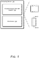
- FIG. 1 illustrates an example computing device 100 implementing the techniques discussed herein.
- the computing device 100 can be, or include, many different types of computing or electronic devices.
- the computing device 100 can be a smartphone or other wireless phone (e.g., a flip-phone or clamshell form factor), a notebook computer (e.g., netbook or ultrabook), a laptop computer, a wearable device (e.g., a smartwatch, an augmented reality headset or device, a virtual reality headset or device), a tablet or phablet computer, a personal media player, an Internet of Things (IoT) device, and so forth.
- IoT Internet of Things
- the computing device 100 includes a foldable display with stiff support 102 and electronics 104.
- the foldable display with stiff support 102 is a flexible material that can be bent or otherwise deformed, and return to its original shape.
- the foldable display with stiff support 102 can be configured as any suitable type of display, such as a light-emitting diode (LED) display, an organic light-emitting diode (OLED) display, a liquid crystal display (LCD), and so forth.
- LED light-emitting diode
- OLED organic light-emitting diode
- LCD liquid crystal display
- the computing device 100 also includes electronics 104.
- Electronics 104 represent hardware components for operating the computing device 100.
- electronics 104 can represent one or more integrated circuit chips and circuitry.
- electronics 104 can include a processor, a microphone, a speaker, a modem, motion detecting sensors, and so forth.
- the computing device 100 is a foldable device that is designed to fold over so that the device is longer or wider while open, and shorter or narrower when closed.
- the computing device 100 can have a clamshell form factor.
- the computing device 100 can be flexible to support one or both of concave bending and convex bending of the foldable display with stiff support 102. Accordingly, although concave bending is shown in some of the figures, the techniques discussed herein can analogously apply to convex bending of the foldable display with stiff support 102.
- FIG. 2 illustrates an example side view of a computing device 100.
- the computing device 100 is a flip-phone having a clamshell form factor.
- the computing device 100 includes a device housing 202 with a base section 204 of the device housing and a flip section 206 of the device housing.
- the computing device 200 includes a foldable display 208 implemented throughout both the base section 204 and the flip section 206 of the device housing 202.
- the foldable display 208 is the foldable display with stiff support 102 of FIG. 1 .
- the computing device 200 is implemented with a hinge system 210 that includes components operable to open and close the flip section 206 of the device housing 202 relative to the base section 204 of the device housing 202. Additionally, the hinge system 210 is operable to fold the foldable display 208 as the flip section 206 of the device housing 202 folds onto the base section 204 of the device housing in a closed position 214 of the mobile device 200. In this example, the foldable display 208 is shown looped in a folded position proximate the hinge system 210 in the closed position 214 of the computing device 100.
- the hinge system 210 opens to the open position 216 of the computing device 102, where the hinge is open to approximately one-hundred eighty degrees (180 deg). As illustrated, when the computing device 102 is in the open position 216 the foldable display is unfolded and extends across both the base section 204 of the device housing and the flip section 206 of the device housing.
- FIG. 3 shows an exploded diagram of the computing device 100 illustrating example layers of a display stack-up 302.
- the computing device 100 with the foldable display with stiff support 102 is shown.
- the display stack-up 302 is arranged at the front of the computing device 100 and includes multiple layers. Each layer has first and second base surfaces and a thickness therebetween that defines a height of a lateral surface at a periphery of the layer at a periphery around a perimeter of the layer.
- the multiple layers are stacked along an axis perpendicular to their base surfaces and parallel to their lateral surfaces.
- the multiple layers in the display stack-up 302 include a stiff support layer 304, an adhesive layer 306, a display layer 308, an optically clear adhesive layer 310, and a cover lens layer 312 stacked as illustrated along an axis that is perpendicular to the face of the computing device 100.
- the stiff support layer 304 Starting at the face of the computing device 100 is the stiff support layer 304, followed by the adhesive layer 306, followed by the display layer 308, followed by the optically clear adhesive layer 310, and followed by the cover lens layer 312 at the very top of the display stack-up 302.
- FIG. 4 shows an example, not covered by the claims, of a cross-sectional view of a display stack-up 400.
- the cross-sectional view in FIG. 4 is a cross-sectional view of the display stack-up of the foldable display 208 along the dashed line A illustrated in FIG. 2 .
- the display stack-up 400 can be, for example, the display stack-up 302 of FIG. 3 .
- the display stack-up 400 makes up a foldable display, and accordingly each layer 304 - 312 of the display stack-up 400 is foldable (is made of a flexible material that can be bent or otherwise deformed, and return to its original shape).
- each layer in the display stack-up 400 includes first and second base surfaces.
- the stiff support layer 304 has a first base surface 402 and a second base surface 404 having a thickness therebetween that defines a height of a lateral surface 406 at a periphery of the stiff support layer 304.
- the layers 304 - 312 are stacked along an axis (y-axis) perpendicular to their base surfaces and parallel to their lateral surfaces.
- the y-axis is perpendicular to a face of a computing device that includes the display stack-up 400.
- the stiff support layer 304 is a stiff support, providing support to the higher layers in the foldable display (layers 306 - 312).
- the stiff support layer 304 can be made of various materials, such as metal (e.g., aluminum or stainless steel), glass, ceramic, graphene, or other composite.
- the stiff support layer 304 has a stiffness of at least 60 gigapascals (GPa) and a thickness in the range of 20 to 60 micrometers ( ⁇ m) .
- the stiff support layer 304 also has a tensile strength in the range of 1500 to 3000 megapascals (MPa). With these characteristics, the stiff support layer 304 has a modulus of elasticity in the range of 60 to 1200 GPa.
- the combination of material properties for the stiff support layer 304 allow for curvature of the display stack-up 400 with bend radius between 2 to 6 millimeters (mm) for the range of thickness and range of anticipated cycles (e.g., opening and closing the flip-phone) in the range of 200 to 200,000.
- the adhesive layer 306 is an adhesive arranged to bind the stiff support layer 304 to the display layer 308.
- the adhesive layer 306 can be made of any of a variety of different low modulus materials (e.g., in the range of 1 to 500 kilopascals (KPa)), such as an acrylate or silicone.
- KPa kilopascals
- the adhesive layer 306 need not be, but can be, an optically clear adhesive layer.
- the adhesive layer 306 has a stiffness in the range of 1 to 100 KPa and a thickness in the range of 10 to 100 ⁇ m.
- the display layer 308 can be any single-layered or multi-layered display structure or assembly used to form images for viewing on the computing device 100.
- the display layer 308 can be, for example, a laminate with thin film electronics and coatings.
- the display layer 308 has a stiffness in the range of 1 to 10 GPa and a thickness in the range of 10 to 100 ⁇ m.
- the display layer 308 is optionally a touch-sensitive layer capable of detecting an object (e.g., a user's finger or stylus) touching the display stack-up 400 (e.g., touching the cover lens layer 312).
- the optically clear adhesive layer 310 is an optically clear adhesive arranged to bind the display layer 308 to the cover lens layer 312.
- the optically clear adhesive layer 310 being optically clear refers to the optically clear adhesive layer 310 not interfering with a user's viewing of images formed on the display layer 308 (e.g., the optically clear adhesive layer 310 is not visible to the user or the user can easily see through the optically clear adhesive layer 310).
- the optically clear adhesive layer 310 can be made of any of a variety of different low modulus materials (e.g., in the range of 1 to 500 KPa), such as an acrylate or silicone. In one or more embodiments, the optically clear adhesive layer 310 has a stiffness in the range of 1 to 100 KPa and a thickness in the range of 10 to 100 ⁇ m.
- the cover lens layer 312 is an outer cover lens for the display stack-up 400, providing protection to the lower layers in the foldable display (layers 304 - 310), such as protection from cuts and scratches.
- the cover lens layer 312 can be made of various materials, such as a plastic/hard coat laminate.
- the cover lens layer 312 has a stiffness in the range of 1 to 10 GPa and a thickness in the range of 10 to 100 ⁇ m.
- the layers 304 - 312 have various different ranges of thicknesses as discussed above.
- the thickness of a layer refers to the depth or height of the layer along the axis perpendicular to the first and second base surfaces of the layer.
- the support layer 304 is 10 ⁇ m thick
- the adhesive layer 306 is 50 ⁇ m thick
- the display layer 308 is 68 ⁇ m
- the optically clear adhesive layer 310 is 25 ⁇ m thick
- the cover lens layer 312 is 60 ⁇ m thick.
- the stiff support layer 304 has a significantly higher stiffness than each of the other layers in the display stack-up 400.
- the stiff support layer can have a stiffness that is at least six times greater than the stiffness of each of the other layers in the display stack-up 400.
- This stiffness of the stiff support layer 304 provides rigid support the other layers in the display stack-up 400 to prevent the stresses from localized loads along discontinuities from damaging the display layer 308 as well as other layers in the display stack-up 400. These discontinuities can take various different forms, such as a crease between two materials, a gap between two materials, a protrusion from a hinge system, and so forth.
- Each of the layers 304 - 312 of the display stack-up 400 has first and second base surfaces as discussed above.
- the surface area of each of these first and second base surfaces, as well as the geometric shapes and dimensions of these first and second base surfaces, of each of these layers 304 - 312 is approximately the same size (e.g., within a threshold amount, such as 95% of one another).
- the first and second base surfaces can each be a rectangle having approximately the same width and length.
- additional layers can optionally be added to the display stack-up of the foldable display with stiff support 102. Any such additional layers are flexible, and have a thickness and stiffness that are not greater than the thickness and stiffness ranges of the layers 306 - 312 discussed above. Furthermore, the stiff support layer 304 has a stiffness that is at least six times greater than the stiffness of any of such additional layers.
- one or more conductive layers used to detect an object (e.g., a user's finger or stylus) touching the display stack-up can be included in the display stack-up. Such a layer can be constructed from, for example, indium tin oxide (ITO) thin films. Additionally or alternatively, the functionality to detect an object touching the display stack-up can be included in the display layer 308.
- ITO indium tin oxide
- FIG. 5 shows an example, not covered by the claims, of a cross-sectional view of a display stack-up with an additional backing.
- FIG. 5 illustrates the protection that the stiff support layer 304 provides to the layers of the display stack-up 400.
- the cross-sectional view in FIG. 4 is a cross-sectional view of the display stack-up of the foldable display along the dashed line B illustrated in FIG. 1 .
- the display stack-up 400 is the same display stack-up 400 as illustrated in FIG. 4 .
- the display stack-up 400 includes a stiff support layer 304, an adhesive layer 306, a display layer 308, an optically clear adhesive layer 310, and a cover lens layer 312 as discussed above.
- the display stack-up 400 is backed by rigid backings 502 and 504.
- one of the rigid backings 502 and 504 is located in the base section 204 of the device housing and the other of the rigid backings 502 and 504 is located in the flip section 206 of the device housing.
- the rigid backings 502 and 504 can be made of any of a variety of materials, such as metal or a composite, and is designed to be rigid rather than flexible. Accordingly, when the display stack-up 400 is folded, the rigid backings 502 and 504 each remain rigid and do not fold.
- the rigid backings 502 and 504 are optionally bound to the stiff support layer 304, such as by an additional adhesive layer (not shown).
- the computing device 100 incorporating the display stack-up 400 typically has a hinge system that allows the computing device 100 to be folded.
- the rigid backings 502 and 504 back part of the display stack-up 400, but there are discontinuities in the hinge system that prevent the rigid backings 502 and 504 from backing the entire display stack-up 400. These discontinuities are illustrated as a gap 506 between rigid backing 502 and rigid backing 504. This gap 506 can contain no material, just empty space.
- pressure applied to the display stack-up 400 in an area above (e.g., along the y-axis) the discontinuities in the hinge system that prevent the rigid backings 502 and 504 from backing the entire display stack-up 400 can deform and damage the display layer 308 as well as other layers of the display stack-up 400.
- An example of such pressure is illustrated as pressure 508, which can be applied by an object (e.g., finger or stylus) touching the cover lens layer 312.
- the stiff support layer 304 spans the discontinuities in the hinge system that prevent the rigid backings 502 and 504 from backing the entire display stack-up 400. Accordingly, the stiff support layer 304 provides support to the additional layers of the display stack-up 400 (e.g., layers 306 - 312) despite the discontinuities in the hinge system that prevent the rigid backings 502 and 504 from backing the entire display stack-up 400.
- the stiffness of the stiff support layer 304 prevents the display layer 308 as well as other layers of the display stack-up 400 from being damaged despite the presence of the hinge system and any discontinuities in the hinge system that prevent the rigid backings 502 and 504 from backing the entire display stack-up 400.
- the stiff support layer 304 provides protection to the layers of the display stack-up 400 in the presence of such additional discontinuities in the rigid backings 502 and 504.
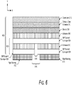
- FIG. 6 shows a cross-sectional view of a display stack-up 600 with an additional backing, according to the present invention.
- the cross-sectional view in FIG. 6 is a cross-sectional view of the display stack-up of the foldable display 208 along the dashed line B illustrated in FIG. 2 .
- the display stack-up 600 makes up a foldable display, and accordingly each layer of the display stack-up 600 is foldable (is made of a flexible material that can be bent or otherwise deformed, and return to its original shape).
- the display stack-up 600 is similar to the display stack-up 400 of FIG.
- stiff support layer 304 of the display stack-up 400 is separated into multiple different sub-layers that support different (but overlapping) portions of the other layers 306 - 312. These different sub-layers result in a stiff support layer 602 having variable thickness.
- the display stack-up 600 includes an adhesive layer 306, a display layer 308, an optically clear adhesive layer 310, and a cover lens layer 312 as discussed above.
- the display stack-up 400 also includes a stiff support layer 602 that includes stiff support sub-layers 604, 606, and 608. In the display stack-up 302 of FIG. 3 discussed above, the stiff support layer 602 can be used as the stiff support layer 304.
- the adhesive layer 306 is an adhesive arranged to bind the stiff support sub-layer 604 to the display layer 308.
- An adhesive layer 610 is an adhesive arranged to bind the stiff support sub-layer 604 to the stiff support sub-layer 606 and the stiff support sub-layer 608.
- the adhesive layer 610 can be made of any of a variety of different low modulus materials (e.g., in the range of 1 to 500 KPa), such as an acrylate or silicone, and can be the same material as used for the adhesive layer 306.
- the adhesive layer 610 need not be, but can be, an optically clear adhesive layer.
- the adhesive layer 610 has a stiffness in the range of 1 to 100 KPa and a thickness in the range of 10 to 100 ⁇ m.
- the stiff support sub-layer 604 is a stiff support, providing support to the higher layers in the foldable display (layers 306 - 308).
- the stiff support sub-layer 604 can be made of various materials, such as metal (e.g., aluminum or stainless steel), glass, ceramic, graphene, or other composite.
- the stiff support sub-layer 604 has a stiffness of at least 60 GPa and a thickness in the range of 20 to 60 ⁇ m.
- the stiff support layer 304 also has a tensile strength in the range of 1500 to 3000 MPa. With these characteristics, the stiff support layer 304 has a modulus of elasticity in the range of 60 to 1200 GPa.
- the combination of material properties for the stiff support sub-layer 604 allow for curvature of the display stack-up 600 with bend radius between 2 to 6 mm for the range of thickness and range of anticipated cycles (e.g., opening and closing the flip-phone) in the range of 200 to 200,000.
- the display stack-up 600 is backed by rigid backings 612 and 614.
- the rigid backings 612 and 614 can be made of any of a variety of materials, such as metal or a composite, and are designed to be rigid rather than flexible.
- the rigid backings 612 and 614 are analogous to the rigid backings 502 and 504, respectively, of FIG. 5 .
- the rigid backings 612 and 614 are optionally bound to the stiff support sub-layers 606 and 608, respectively.
- the computing device 100 incorporating the display stack-up 600 typically has a hinge system that allows the computing device 100 to be folded.
- the rigid backings 612 and 614 back part of the display stack-up 600, but there are discontinuities in the hinge system that prevent the rigid backings 612 and 614 from backing the entire display stack-up 600. These discontinuities are illustrated as a gap 616 between rigid backing 612 and rigid backing 614. Although a single gap 616 of discontinuities in the rigid backings 612 and 614 is illustrated in FIG. 6 , it should be noted that in some situations there can be additional areas of discontinuities in the rigid backings 612 and 614, such as areas between mating housing surfaces or other features (e.g., holes or cutouts) in the device housing that are needed for assembly of the computing device).
- the stiff support sub-layer 604 spans the discontinuities in the hinge system (and optionally additional areas of discontinuities in the rigid backings 612 and 614) that prevent the rigid backings 612 and 614 from backing the entire display stack-up 600. Accordingly, the stiff support sub-layer 604 provides support to the additional layers of the display stack-up 600 (e.g., layers 306 - 312) despite the discontinuities in the hinge system (and optionally additional areas of discontinuities in the rigid backings 612 and 614) that prevent the rigid backings 612 and 614 from backing the entire display stack-up 600.
- stiffness of the stiff support sub-layer 604 prevents the display layer 308 as well as other layers of the display stack-up 600 from being damaged despite the presence of the hinge system and any discontinuities in the hinge system that prevent the rigid backings 612 and 614 from backing the entire display stack-up 600.
- the stiff support sub-layers 606 and 608 provide further support to the additional layers of the display stack-up 600 (e.g., layers 306 - 312), although there is a gap 618 between stiff support sub-layer 606 and stiff support sub-layer 608.
- one of the stiff support sub-layers 606 and 608 is located in the base section 204 of the device housing and the other of the stiff support sub-layers 606 and 608 is located in the flip section 206 of the device housing.
- the gap 618 corresponds to part of the discontinuities illustrated as a gap 616 between rigid backing 612 and rigid backing 614 (e.g., this gap can contain no material, just empty space).
- the gap 618 is narrower (shorter along the x-axis) than the gap 616. In one or more embodiments, the gap 618 is approximately 75% of the length of the gap 616 (e.g., the gap 616 may be approximately 21 mm and the gap 618 may be approximately 16 mm).
- Each stiff support sub-layer 606 and 608 is a stiff support, providing support to the higher layers in the foldable display (layers 306 - 308).
- Each stiff support sub-layer 606 and 608 can be made of various materials, such as metal (e.g., aluminum or stainless steel), glass, ceramic, graphene, or other composite.
- each stiff support sub-layer 606 and 608 has a stiffness of at least 60 GPa, a thickness in the range of 20 to 60 ⁇ m, and a tensile strength in the range of 1500 to 3000 MPa. With these characteristics, each stiff support sub-layer 606 and 608 has a modulus of elasticity in the range of 60 to 1200 GPa.
- each of the stiff support sub-layers 606 and 608 have first and second base surfaces, analogous to the first and second base surfaces of the layers 304 - 312 discussed above.
- Each of these stiff support sub-layers 606 and 608 can have first and second base surfaces with geometric shapes that differ from the geometric shapes of the first and second base surfaces of the layers 604 and 306 - 312.
- each of these stiff support sub-layers 606 and 608 has first and second base surfaces with at least one dimension that is less than the corresponding dimension of the layers 604 and 306 - 312.
- the first and second base surfaces of each of the layers 604 and 306 - 312 can be rectangles that are 6 centimeters (cm) wide and 15 cm long.
- the first and second base surfaces of each of the stiff support sub-layers 606 and 608 can be rectangles that are 6 cm wide and 12 cm long.
- the stiff support sub-layer 604 provides protection to the layers of the display stack-up 600 in the presence of such additional discontinuities in the rigid backings 612 and 614.
- the stiff support sub-layer 606 and/or sub-layer 608 optionally also provide protection to the layers of the display stack-up 600 in the presence of such additional discontinuities in the rigid backings 612 and 614.
- stiff support sub-layers 604, 606, and 608 are illustrated in FIG. 6
- additional stiff support sub-layers could be included between the stiff support sub-layer 604 and the display layer 308, between the stiff support sub-layer 604 and a stiff support sub-layer 606 or 608, between the stiff support sub-layer 606 and the rigid backing 612, between the stiff support sub-layer 608 and the rigid backing 614, combinations thereof, and so forth.
- Any such stiff support sub-layer would be flexible, and have a thickness and stiffness that are not greater than the thickness and stiffness ranges of the stiff support sub-layers 604, 606, and 608.
- the stiff support sub-layers 606 and 608 support the curvature of the foldable display and protects against hinge/plate discontinuity when the computing device 100 is in the closed position as well as when transitioning between the closed and open positions.
- the stiff support sub-layer 604 provides protection to the layers of the display stack-up 600 in the presence of discontinuities in the rigid backings 612 and 614, such as discontinuities resulting from the hinge system of the computing device, areas between mating housing surfaces or other features (e.g., holes or cutouts) in the device housing that are needed for assembly of the computing device), and so forth.
- the stiff support sub-layers 606 and 608 provide support and protection to the layers in the display stack-up 600 at the discontinuities where the rigid backings 612 and 614 end and the curvature of the display stack-up 600 begins (when the computing device is in a closed position or transitioning between the closed and open positions).
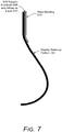
- FIG. 7 illustrates an example side-view of a foldable display stack-up with multiple stiff support sub-layers.
- FIG. 7 illustrates a display stack-up portion 700, the stiff support sub-layer 608 and adhesive layer 610, and the rigid backing 614.
- the display stack-up portion 700 is a portion of the display stack-up 600 of FIG. 6 , and includes the stiff support sub-layer 604, the adhesive layer 306, the display layer 308, the optically clear adhesive layer 310, and the cover lens layer 312 (the layers of the display stack-up 600 other than the adhesive layer 610 and the stiff support sub-layers 606 and 608).
- the display stack-up portion 700 is illustrated in FIG. 7 in its folded or closed position.
- the display stack-up portion 700 is a portion of the foldable display 208 of FIG. 2 (the foldable display 208 without the stiff support sub-layers 606 and 608 and adhesive layer 610) when the computing device 100 is in the closed position 214.
- the stiff support sub-layer 608 and adhesive layer 610 extend beyond the rigid backing 614, providing additional support for the curvature of the display stack-up 600 and protecting against discontinuities resulting from the hinge system or the rigid backing 614 while the computing device 100 is in the closed position or is transitioning between the closed and open positions.
- the stiff support sub-layer 608 protects against the discontinuity at the end of the rigid backing 614 there is a transition from having the support of the rigid backing 614 and not having the support of the rigid backing 614 (e.g., where the display stack-up portion 700 begins to bend as illustrated).
- FIG. 8 illustrates an example process 800 for implementing the techniques discussed herein in accordance with one or more embodiments.
- Process 800 is carried out by a computing device or system, such as a computing system for making flexible display stack-ups for electronic devices using thin-film laminate technology, and can be implemented in hardware or combinations of hardware with software or firmware.
- Process 800 is shown as a set of acts and is not limited to the order shown for performing the operations of the various acts.
- multiple layers of a foldable display stack-up are stacked along an axis perpendicular to first and second base surfaces of the multiple layers and parallel to the lateral surfaces of the layers (act 802).
- These multiple layers include the display layer and the stiff support layer discussed above, as well as optionally additional layers such as the cover lens layer.
- the stiff support layer has a stiffness that is at least six times greater than the stiffness of the display layer as discussed above.
- Each of the multiple layers is bound to another of the multiple layers using an adhesive layer (act 804).
- This binding includes binding the display layer to the stiff support layer using an adhesive layer as discussed above.
- FIG. 9 illustrates various components of an example electronic device 900 that can be implemented as a computing device as described with reference to any of the previous FIGs. 1-8 .
- the device 900 may be implemented as any one or combination of a fixed or mobile device in any form of a consumer, computer, portable, user, communication, phone, navigation, gaming, messaging, Web browsing, paging, media playback, or other type of electronic device.
- the electronic device 900 can include one or more data input components 902 via which any type of data, media content, or inputs can be received such as user-selectable inputs, messages, music, television content, recorded video content, and any other type of audio, video, or image data received from any content or data source.
- the data input components 902 may include various data input ports such as universal serial bus ports, coaxial cable ports, and other serial or parallel connectors (including internal connectors) for flash memory, DVDs, compact discs, and the like. These data input ports may be used to couple the electronic device to components, peripherals, or accessories such as keyboards, microphones, or cameras.
- the data input components 902 may also include various other input components such as microphones, touch sensors, keyboards, and so forth.
- the electronic device 900 of this example includes a processor system 904 (e.g., any of microprocessors, controllers, and the like) or a processor and memory system (e.g., implemented in a system on a chip), which processes computer executable instructions to control operation of the device 900.
- a processor system 904 may be implemented at least partially in hardware that can include components of an integrated circuit or on-chip system, an application specific integrated circuit, a field programmable gate array, a complex programmable logic device, and other implementations in silicon or other hardware.
- the electronic device 900 can be implemented with any one or combination of software, hardware, firmware, or fixed logic circuitry implemented in connection with processing and control circuits that are generally identified at 906.
- the electronic device 900 can include a system bus or data transfer system that couples the various components within the device 900.
- a system bus can include any one or combination of different bus structures such as a memory bus or memory controller, a peripheral bus, a universal serial bus, or a processor or local bus that utilizes any of a variety of bus architectures.
- the electronic device 900 also includes one or more memory devices 908 that enable data storage such as random access memory, nonvolatile memory (e.g., read only memory, flash memory, erasable programmable read only memory, electrically erasable programmable read only memory, etc.), and a disk storage device.
- a memory device 908 provides data storage mechanisms to store the device data 910, other types of information or data (e.g., data backed up from other devices), and various device applications 912 (e.g., software applications).
- an operating system 914 can be maintained as software instructions with a memory device and executed by the processor system 904.
- the techniques discussed herein can be implemented as a computer-readable storage medium having computer readable code stored thereon for programming a computing device (for example, a processor of a computing device) to perform a method as discussed herein.
- Computer-readable storage media refers to media and/or devices that enable persistent and/or non-transitory storage of information in contrast to mere signal transmission, carrier waves, or signals per se.
- Computer-readable storage media refers to non-signal bearing media.
- Examples of such computer-readable storage mediums include, but are not limited to, a hard disk, a CD-ROM, an optical storage device, a magnetic storage device, a ROM (Read Only Memory), a PROM (Programmable Read Only Memory), an EPROM (Erasable Programmable Read Only Memory), an EEPROM (Electrically Erasable Programmable Read Only Memory) and a Flash memory.
- the computer-readable storage medium can be, for example, memory devices 908.
- the electronic device 900 also includes a transceiver 920 that supports wireless and/or wired communication with other devices or services allowing data and control information to be sent as well as received by the device 900.
- the wireless and/or wired communication can be supported using any of a variety of different public or proprietary communication networks or protocols such as cellular networks (e.g., 3G networks, 4G networks such as LTE networks, 5G networks), wireless local area networks such as Wi-Fi networks, and so forth.
- the electronic device 900 also includes an audio or video processing system 922 that processes audio data or passes through the audio and video data to an audio system 924 or to a foldable display with stiff support 102.
- the foldable display with stiff support 102 also displays images generated by other components of the electronic device 900, such as images generated by the device applications 912, by the operating system 914, and so forth.
- the audio system or the display system may include any devices that process, display, play, or otherwise render audio, video, display, or image data.
- Display data and audio signals can be communicated to an audio component (e.g., a speaker) or to a display component via a radio frequency link, S-video link, high definition multimedia interface (HDMI), composite video link, component video link, digital video interface, analog audio connection, or other similar communication link, such as media data port 928.
- the audio system or the display system are external components to the electronic device.
- the display system can be an integrated component of the example electronic device, such as part of an integrated touch interface.
Landscapes
- Engineering & Computer Science (AREA)
- Theoretical Computer Science (AREA)
- Computer Hardware Design (AREA)
- Physics & Mathematics (AREA)
- General Physics & Mathematics (AREA)
- General Engineering & Computer Science (AREA)
- Human Computer Interaction (AREA)
- Signal Processing (AREA)
- Mathematical Physics (AREA)
- Devices For Indicating Variable Information By Combining Individual Elements (AREA)
Claims (10)
- Klappbarer Anzeigestapelaufbau, der Folgendes umfasst:eine Anzeigeschicht (308), die konfiguriert ist, um Bilder zum Betrachten auszubilden, wobei die Anzeigeschicht (308) flexibel und imstande ist, sich zu biegen;eine steife Trägerschicht (304), die die Anzeigeschicht (308) trägt, wobei die steife Trägerschicht (304) flexibel und imstande ist, sich zu biegen, wobei die Anzeigeschicht (304) und die steife Trägerschicht (308) jeweils eine erste und eine zweite Basisoberfläche und eine Dicke zwischen der ersten und der zweiten Basisoberfläche aufweisen, die eine Höhe einer Seitenoberfläche an einem Umfang der Schicht definiert, wobei die Anzeigeschicht (304) und die steife Trägerschicht (308) entlang einer Achse senkrecht zu ihren ersten und zweiten Basisoberflächen und parallel zu ihren Seitenoberflächen gestapelt werden, wobei die steife Trägerschicht (304) Folgendes einschließt:eine erste steife Trägerteilschicht (604), die eine erste und eine zweite Basisoberfläche aufweist, die ungefähr dieselbe geometrische Form und Abmessungen wie die erste und die zweite Basisoberfläche der Anzeigeschicht (308) aufweisen;eine zweite steife Trägerteilschicht (606) und eine dritte steife Trägerteilschicht (608), die jeweils eine erste und eine zweite Basisoberfläche mit wenigstens einer Abmessung aufweisen, die kleiner als die entsprechende Abmessung der ersten und der zweiten Basisoberfläche der Anzeigeschicht (308) ist, was zu einem Spalt (618) zwischen der zweiten steifen Trägerteilschicht (606) und der dritten steifen Trägerteilschicht (608) an einer Stelle entlang einer Achse parallel zu der ersten und der zweiten Basisoberfläche führt, wo die erste steife Trägerteilschicht (604) keinen Spalt aufweist;eine erste starre Rückseite (612) und eine zweite starre Rückseite (614), die jeweils eine erste und eine zweite Basisoberfläche mit wenigstens einer Abmessung aufweisen, die kleiner als die entsprechende Abmessung der ersten und der zweiten Basisoberflächen der zweiten steifen Trägerteilschicht (606) und der dritten steifen Trägerteilschicht (608) ist, was zu einem Spalt (616) zwischen der ersten starren Rückseite (612) und der zweiten starren Rückseite (614) an einer Stelle entlang einer Achse parallel zu der ersten und der zweiten Basisoberfläche führt, die den Spalt (618) zwischen der zweiten steifen Trägerteilschicht (606) und der dritten steifen Trägerteilschicht (608) überlappt und der größer als der Spalt (618) zwischen der zweiten steifen Trägerteilschicht (606) und der dritten steifen Trägerteilschicht (608) ist;eine Klebstoffschicht (306), die einen Kleber einschließt, der angeordnet ist, um die Anzeigeschicht (308) an die steife Trägerschicht (304) zu binden, wobei die steife Trägerschicht (304) eine Steifigkeit aufweist, die wenigstens sechsmal größer als die Steifigkeit der Klebstoffschicht (306) und wenigstens sechsmal größer als die Steifigkeit der Anzeigeschicht (308) ist; undeine Abdeckungslinsenschicht (312), die konfiguriert ist, um die Anzeigeschicht (308) zu schützen; undeine optisch klare Klebstoffschicht (310), die einen optisch klaren Klebstoff einschließt, der angeordnet ist, um die Anzeigeschicht (308) an die Abdeckungslinsenschicht (312) zu binden, wobei die optisch klare Klebstoffschicht (310) die Abdeckungslinsenschicht (312) an eine entgegengesetzte Oberfläche der Anzeigeschicht bindet als die Klebstoffschicht die steife Trägerschicht bindet.
- Anzeigestapelaufbau nach Anspruch 1, wobei die steife Trägerschicht (304) zwischen der Anzeigeschicht (308) und einem Gehäuse (202) einer Rechenvorrichtung (100) gelegen ist, die den Anzeigestapelaufbau einschließt.
- Anzeigestapelaufbau nach Anspruch 1 oder 2, wobei die steife Trägerschicht (304) eine Steifigkeit von wenigstens 60 Gigapascal aufweist.
- Anzeigestapelaufbau nach einem der vorhergehenden Ansprüche, wobei die steife Trägerschicht (304) eine Dicke in einem Bereich von 20 bis 60 Mikrometern aufweist.
- Anzeigestapelaufbau nach Anspruch 1, wobei die erste steife Trägerteilschicht (604), die zweite steife Trägerteilschicht (606) und die dritte steife Trägerteilschicht (608) jeweils eine Steifigkeit von wenigstens 60 Gigapascal aufweisen.
- Anzeigestapelaufbau nach Anspruch 1 oder 5, wobei die erste steife Trägerteilschicht (604), die zweite steife Trägerteilschicht (606) und die dritte steife Trägerteilschicht (608) jeweils eine Dicke in einem Bereich von 20 bis 60 Mikrometern aufweisen.
- Anzeigestapelaufbau nach einem der Ansprüche 1, 5 oder 6, wobei sich die zweite steife Trägerteilschicht (606) in einem Basisabschnitt (204) eines Gehäuses (202) einer Rechenvorrichtung (100) befindet, die den Anzeigestapelaufbau einschließt, und sich die dritte steife Trägerteilschicht (608) in einem Flip-Abschnitt (206) des Gehäuses (202) befindet.
- Verfahren zum Erzeugen einer klappbaren Anzeige, wobei das Verfahren Folgendes umfasst:Stapeln mehrerer Schichten einschließlich einer Anzeigeschicht (308), einer steifen Trägerschicht (304), einer ersten starren Rückseite (612) und einer zweiten starren Rückseite (614), wobei die Anzeigeschicht (308) konfiguriert ist, um Bilder zum Betrachten auszubilden und flexibel und imstande zu sein, sich zu biegen, wobei die steife Trägerschicht (304) die Anzeigeschicht (308) trägt und flexibel und imstande ist, sich zu biegen, wobei die Anzeigeschicht (308) und die steife Trägerschicht (304) jeweils eine erste und eine zweite Basisoberfläche und eine Dicke zwischen der ersten und zweiten Basisoberfläche aufweisen, die eine Höhe einer Seitenoberfläche an einem Umfang der Schicht definiert, wobei das Stapeln das Stapeln der Anzeigeschicht (308) und der steifen Trägerschicht (304) entlang einer Achse senkrecht zu ihren ersten und zweiten Basisoberflächen und parallel zu ihren Seitenoberflächen einschließt, wobei die steife Trägerschicht (304) eine erste steife Trägerteilschicht (604), eine zweite steife Trägerteilschicht (606) und eine dritte steife Trägerteilschicht (608) einschließt, wobei die erste steife Trägerteilschicht (604) eine erste und eine zweite Basisoberfläche aufweist, die ungefähr dieselbe geometrische Form und Abmessungen wie die erste und die zweite Basisoberfläche der Anzeigeschicht (308) aufweisen, wobei die zweite steife Trägerteilschicht (606) und die dritte steife Trägerteilschicht (608) jeweils eine erste und eine zweite Basisoberfläche mit wenigstens einer Abmessung aufweisen, die kleiner als die entsprechende Abmessung der ersten und der zweiten Basisoberfläche der Anzeigeschicht (308) ist, was zu einem Spalt (618) zwischen der zweiten steifen Trägerteilschicht (606) und der dritten steifen Trägerteilschicht (608) an einer Stelle entlang einer Achse parallel zu der ersten und der zweiten Basisoberfläche führt, wo die erste steife Trägerteilschicht (604) keinen Spalt aufweist, wobei die erste starre Rückseite (612) und die zweite starre Rückseite (614) jeweils eine erste und eine zweite Basisoberfläche mit wenigstens einer Abmessung aufweisen, die kleiner als die entsprechende Abmessung der ersten und der zweiten Basisoberfläche der zweiten steifen Trägerteilschicht (606) und der dritten steifen Trägerteilschicht (608) ist, was zu einem Spalt (616) zwischen der ersten starren Rückseite (612) und der zweiten starren Rückseite (614) an einer Stelle entlang einer Achse parallel zu der ersten und der zweiten Basisoberfläche führt, die den Spalt zwischen der zweiten steifen Trägerteilschicht (606) und der dritten steifen Trägerteilschicht (608) überlappt und der größer als der Spalt (618) zwischen der zweiten steifen Trägerteilschicht (606) und der dritten steifen Trägerteilschicht (608) ist; undBinden der Anzeigeschicht (308) an die steife Trägerschicht (304) unter Verwendung einer Klebstoffschicht (306), wobei die steife Trägerschicht (304) eine Steifigkeit aufweist, die wenigstens sechsmal größer als die Steifigkeit der Klebstoffschicht (306) und wenigstens sechsmal größer als die Steifigkeit der Anzeigeschicht (308) ist;wobei die mehreren Schichten ferner eine Abdeckungslinsenschicht (312) einschließen, die die Anzeigeschicht (308) schützt, wobei das Verfahren ferner Folgendes umfasst:
Binden der Abdeckungslinsenschicht (312) an die Anzeigeschicht (308) unter Verwendung eines optisch klaren Klebstoffs (310), wobei das Binden das Binden der Abdeckungslinsenschicht (312) an eine entgegengesetzte Oberfläche der Anzeigeschicht (308) einschließt als an diejenige, an die die steife Trägerschicht (304) gebunden ist. - Verfahren nach Anspruch 8, wobei das Binden der Anzeigeschicht (308) an die steife Trägerschicht (304) das Binden der Anzeigeschicht (308) an die erste steife Trägerteilschicht (604) und das Binden der zweiten steifen Trägerteilschicht (606) und der dritten steifen Trägerteilschicht (608) an die erste steife Trägerteilschicht (604) umfasst.
- Rechenvorrichtung (100), die Folgendes umfasst: ein Gehäuse (202) und einen klappbaren Anzeigestapelaufbau nach einem der Ansprüche 1 bis 7.
Applications Claiming Priority (1)
| Application Number | Priority Date | Filing Date | Title |
|---|---|---|---|
| US16/262,266 US10795415B2 (en) | 2019-01-30 | 2019-01-30 | Foldable display with stiff support |
Publications (2)
| Publication Number | Publication Date |
|---|---|
| EP3690600A1 EP3690600A1 (de) | 2020-08-05 |
| EP3690600B1 true EP3690600B1 (de) | 2021-12-01 |
Family
ID=69411225
Family Applications (1)
| Application Number | Title | Priority Date | Filing Date |
|---|---|---|---|
| EP20154440.0A Active EP3690600B1 (de) | 2019-01-30 | 2020-01-29 | Faltbare anzeige mit steifer stütze |
Country Status (4)
| Country | Link |
|---|---|
| US (1) | US10795415B2 (de) |
| EP (1) | EP3690600B1 (de) |
| KR (1) | KR20200094633A (de) |
| CN (1) | CN111508351B (de) |
Families Citing this family (18)
| Publication number | Priority date | Publication date | Assignee | Title |
|---|---|---|---|---|
| CN110557481B (zh) * | 2019-08-28 | 2021-06-15 | 华为技术有限公司 | 电子设备 |
| CN110599907A (zh) * | 2019-09-05 | 2019-12-20 | 武汉华星光电半导体显示技术有限公司 | 一种可折叠显示装置 |
| CN110792905B (zh) * | 2019-11-19 | 2021-08-27 | 京东方科技集团股份有限公司 | 支撑结构及显示装置 |
| CN111179762A (zh) * | 2020-03-06 | 2020-05-19 | 上海天马微电子有限公司 | 一种折叠显示装置 |
| US11554575B2 (en) * | 2020-06-24 | 2023-01-17 | Motorola Mobility Llc | Composite display cover |
| CN112150930A (zh) * | 2020-09-27 | 2020-12-29 | 武汉华星光电半导体显示技术有限公司 | 显示装置 |
| WO2022080885A1 (ko) * | 2020-10-14 | 2022-04-21 | 삼성전자 주식회사 | 플렉서블 디스플레이를 포함하는 전자 장치 |
| KR20220060605A (ko) * | 2020-11-04 | 2022-05-12 | 삼성디스플레이 주식회사 | 표시 장치 |
| KR102832950B1 (ko) | 2020-11-10 | 2025-07-11 | 삼성디스플레이 주식회사 | 표시 장치 |
| CN113035059B (zh) * | 2021-02-26 | 2022-08-02 | 武汉华星光电半导体显示技术有限公司 | 显示模组 |
| TWI767591B (zh) * | 2021-03-03 | 2022-06-11 | 富世達股份有限公司 | 鉸鏈 |
| US12115771B2 (en) * | 2021-06-07 | 2024-10-15 | Apple Inc. | Electronic devices with multilayer adhesive |
| KR20230000277A (ko) * | 2021-06-24 | 2023-01-02 | 삼성전자주식회사 | 플렉서블 디스플레이 및 그 플렉서블 디스플레이를 포함하는 전자 장치 |
| KR20230033772A (ko) | 2021-09-01 | 2023-03-09 | 엘지디스플레이 주식회사 | 표시 패널 및 이를 포함하는 표시 장치 |
| CN114495741B (zh) * | 2022-02-10 | 2023-06-27 | 武汉华星光电半导体显示技术有限公司 | 显示模组及终端设备 |
| WO2025005439A1 (ko) * | 2023-06-30 | 2025-01-02 | 삼성전자주식회사 | 플렉서블 디스플레이의 파손을 감소시키기 위한 구조를 포함하는 전자 장치 |
| US12353246B2 (en) | 2023-08-29 | 2025-07-08 | Google Llc | Narrow display borders using a display-to-frame interposer |
| US20250328163A1 (en) * | 2024-04-18 | 2025-10-23 | Google Llc | Foldable screen mesh imprints prevention |
Family Cites Families (29)
| Publication number | Priority date | Publication date | Assignee | Title |
|---|---|---|---|---|
| US5436744A (en) * | 1993-09-03 | 1995-07-25 | Motorola Inc. | Flexible liquid crystal display with integrated driver circuit and display electrodes formed on opposite sides of folded substrate |
| KR100944886B1 (ko) * | 2001-10-30 | 2010-03-03 | 가부시키가이샤 한도오따이 에네루기 켄큐쇼 | 반도체 장치의 제조 방법 |
| JP5471035B2 (ja) * | 2009-05-26 | 2014-04-16 | ソニー株式会社 | 表示装置、表示装置の製造方法、および電子機器 |
| US8890823B2 (en) * | 2012-01-09 | 2014-11-18 | Motorola Mobility Llc | System and method for reducing occurrences of unintended operations in an electronic device |
| US20130057557A1 (en) * | 2011-09-07 | 2013-03-07 | Qualcomm Mems Technologies, Inc. | High area stacked layered metallic structures and related methods |
| KR101876540B1 (ko) * | 2011-12-28 | 2018-07-10 | 삼성디스플레이 주식회사 | 가요성 표시 장치 및 가요성 표시 장치의 제조 방법 |
| US9116567B2 (en) * | 2012-04-25 | 2015-08-25 | Google Technology Holdings LLC | Systems and methods for managing the display of content on an electronic device |
| KR102265083B1 (ko) * | 2013-08-22 | 2021-06-15 | 삼성전자주식회사 | 가변강성 필름, 가변강성 유연 디스플레이 및 이의 제조 방법 |
| WO2015148779A1 (en) * | 2014-03-27 | 2015-10-01 | Polyera Corporation | Optimal mounting of a flexible display |
| KR102319835B1 (ko) * | 2014-09-22 | 2021-11-01 | 엘지디스플레이 주식회사 | 접이식 디스플레이 장치 |
| US9759937B2 (en) * | 2015-04-29 | 2017-09-12 | Apple Inc. | Display with integrated backlight |
| US9983424B2 (en) * | 2015-06-08 | 2018-05-29 | Lg Display Co., Ltd. | Foldable display device |
| KR102369943B1 (ko) * | 2015-06-25 | 2022-03-03 | 삼성디스플레이 주식회사 | 폴더블 표시 장치 |
| US9778772B2 (en) * | 2015-09-16 | 2017-10-03 | Microsoft Technology Licensing, Llc | Bendable device with display in movable connection with body |
| DE102016121942B4 (de) * | 2015-11-30 | 2024-07-25 | Lg Display Co., Ltd. | Faltbare Anzeigevorrichtung |
| KR20170064453A (ko) * | 2015-11-30 | 2017-06-09 | 엘지디스플레이 주식회사 | 폴더블 표시장치 |
| CN108430763B (zh) * | 2015-12-22 | 2021-07-16 | 3M创新有限公司 | 具有分立的粘合剂贴片的粘结层 |
| US10063677B2 (en) * | 2016-03-18 | 2018-08-28 | Motorola Mobility Llc | Electronic device with flexible display and hinged housing, and corresponding systems and methods |
| US9913392B2 (en) | 2016-04-13 | 2018-03-06 | Motorola Mobility Llc | Flexible display stack-up and method for arranging |
| US10503209B2 (en) * | 2016-08-18 | 2019-12-10 | Lenovo (Singapore) Pte. Ltd. | Electronic device with structural layer |
| KR102680552B1 (ko) * | 2016-11-30 | 2024-07-01 | 엘지디스플레이 주식회사 | 커버 플레이트 및 이를 포함하는 폴더블 표시장치 |
| US10409335B2 (en) * | 2016-12-12 | 2019-09-10 | Motorola Mobility Llc | Method to recover permanent set in a foldable display |
| KR102672832B1 (ko) * | 2016-12-30 | 2024-06-05 | 엘지디스플레이 주식회사 | 폴더블 표시 장치 |
| US10033015B1 (en) * | 2017-04-07 | 2018-07-24 | Motorola Mobility Llc | Flexible, optically clear, composite structures for foldable displays in mobile devices |
| KR102356866B1 (ko) * | 2017-04-10 | 2022-02-03 | 삼성디스플레이 주식회사 | 폴더블 표시 장치 및 이의 제조 방법 |
| KR102362080B1 (ko) * | 2017-05-31 | 2022-02-10 | 엘지디스플레이 주식회사 | 폴더블 표시장치 |
| US10268238B2 (en) * | 2017-06-08 | 2019-04-23 | Google Llc | Foldable display neutral axis management with thin, high modulus layers |
| KR102547854B1 (ko) * | 2018-05-04 | 2023-06-26 | 삼성디스플레이 주식회사 | 폴더블 표시 장치 및 폴더블 표시 장치의 제조 방법 |
| CN109147573B (zh) * | 2018-10-09 | 2019-12-31 | 武汉华星光电半导体显示技术有限公司 | 一种显示装置、保护盖板 |
-
2019
- 2019-01-30 US US16/262,266 patent/US10795415B2/en active Active
- 2019-12-02 CN CN201911213565.7A patent/CN111508351B/zh active Active
- 2019-12-24 KR KR1020190173974A patent/KR20200094633A/ko not_active Ceased
-
2020
- 2020-01-29 EP EP20154440.0A patent/EP3690600B1/de active Active
Also Published As
| Publication number | Publication date |
|---|---|
| KR20200094633A (ko) | 2020-08-07 |
| CN111508351A (zh) | 2020-08-07 |
| CN111508351B (zh) | 2022-04-19 |
| EP3690600A1 (de) | 2020-08-05 |
| US20200241594A1 (en) | 2020-07-30 |
| US10795415B2 (en) | 2020-10-06 |
Similar Documents
| Publication | Publication Date | Title |
|---|---|---|
| EP3690600B1 (de) | Faltbare anzeige mit steifer stütze | |
| US11147170B2 (en) | Display panels and display devices | |
| US9971436B2 (en) | Touch user interface at a display edge | |
| US10775849B2 (en) | Flexible device and method for manufacturing same | |
| EP3278326B1 (de) | Virtuelle grenzenlose anzeige | |
| CN109688245B (zh) | 具有显示模块的电子装置 | |
| CN202929522U (zh) | 信息处理设备 | |
| CN103092405B (zh) | 触摸屏面板及其制造方法和具有该触摸屏面板的移动装置 | |
| US8760394B2 (en) | Portable electronic device and switching method of icon | |
| CN107545843B (zh) | 包括窗部件的显示装置 | |
| US20220183174A1 (en) | Electronic device including flexible display | |
| EP4020071B1 (de) | Faltbarer anzeigebildschirm, herstellungsverfahren dafür und anzeigevorrichtung | |
| US20200333844A1 (en) | Flexible display device | |
| US20250147548A1 (en) | Foldable display device | |
| US20140285733A1 (en) | Touch display apparatus and method for manufacturing the same | |
| KR102356723B1 (ko) | 커버 윈도우 및 이를 포함하는 표시 장치 | |
| CN108881540A (zh) | 显示屏组件及电子设备 | |
| WO2020123758A1 (en) | Cover window of foldable display | |
| US8688177B2 (en) | Double-folded flexible printed circuit board for slider-type mobile devices | |
| KR102018228B1 (ko) | 이동 단말기 및 이의 제조 방법 | |
| CN111775532B (zh) | 显示屏保护膜及电子设备 | |
| CN111381704B (zh) | 触控显示模组及电子终端 | |
| CN112700728A (zh) | 显示模组及电子设备 | |
| US11335258B2 (en) | Information handling system thin display with minimal bezel | |
| KR20260006111A (ko) | 표시 장치 및 이의 제조 방법 |
Legal Events
| Date | Code | Title | Description |
|---|---|---|---|
| PUAI | Public reference made under article 153(3) epc to a published international application that has entered the european phase |
Free format text: ORIGINAL CODE: 0009012 |
|
| STAA | Information on the status of an ep patent application or granted ep patent |
Free format text: STATUS: THE APPLICATION HAS BEEN PUBLISHED |
|
| AK | Designated contracting states |
Kind code of ref document: A1 Designated state(s): AL AT BE BG CH CY CZ DE DK EE ES FI FR GB GR HR HU IE IS IT LI LT LU LV MC MK MT NL NO PL PT RO RS SE SI SK SM TR |
|
| AX | Request for extension of the european patent |
Extension state: BA ME |
|
| STAA | Information on the status of an ep patent application or granted ep patent |
Free format text: STATUS: REQUEST FOR EXAMINATION WAS MADE |
|
| 17P | Request for examination filed |
Effective date: 20210127 |
|
| RBV | Designated contracting states (corrected) |
Designated state(s): AL AT BE BG CH CY CZ DE DK EE ES FI FR GB GR HR HU IE IS IT LI LT LU LV MC MK MT NL NO PL PT RO RS SE SI SK SM TR |
|
| GRAJ | Information related to disapproval of communication of intention to grant by the applicant or resumption of examination proceedings by the epo deleted |
Free format text: ORIGINAL CODE: EPIDOSDIGR1 |
|
| STAA | Information on the status of an ep patent application or granted ep patent |
Free format text: STATUS: GRANT OF PATENT IS INTENDED |
|
| GRAP | Despatch of communication of intention to grant a patent |
Free format text: ORIGINAL CODE: EPIDOSNIGR1 |
|
| INTG | Intention to grant announced |
Effective date: 20210706 |
|
| GRAS | Grant fee paid |
Free format text: ORIGINAL CODE: EPIDOSNIGR3 |
|
| GRAA | (expected) grant |
Free format text: ORIGINAL CODE: 0009210 |
|
| STAA | Information on the status of an ep patent application or granted ep patent |
Free format text: STATUS: THE PATENT HAS BEEN GRANTED |
|
| AK | Designated contracting states |
Kind code of ref document: B1 Designated state(s): AL AT BE BG CH CY CZ DE DK EE ES FI FR GB GR HR HU IE IS IT LI LT LU LV MC MK MT NL NO PL PT RO RS SE SI SK SM TR |
|
| REG | Reference to a national code |
Ref country code: GB Ref legal event code: FG4D |
|
| REG | Reference to a national code |
Ref country code: AT Ref legal event code: REF Ref document number: 1452382 Country of ref document: AT Kind code of ref document: T Effective date: 20211215 Ref country code: CH Ref legal event code: EP |
|
| REG | Reference to a national code |
Ref country code: IE Ref legal event code: FG4D |
|
| REG | Reference to a national code |
Ref country code: DE Ref legal event code: R096 Ref document number: 602020001121 Country of ref document: DE |
|
| REG | Reference to a national code |
Ref country code: LT Ref legal event code: MG9D |
|
| REG | Reference to a national code |
Ref country code: NL Ref legal event code: MP Effective date: 20211201 |
|
| REG | Reference to a national code |
Ref country code: AT Ref legal event code: MK05 Ref document number: 1452382 Country of ref document: AT Kind code of ref document: T Effective date: 20211201 |
|
| PG25 | Lapsed in a contracting state [announced via postgrant information from national office to epo] |
Ref country code: RS Free format text: LAPSE BECAUSE OF FAILURE TO SUBMIT A TRANSLATION OF THE DESCRIPTION OR TO PAY THE FEE WITHIN THE PRESCRIBED TIME-LIMIT Effective date: 20211201 Ref country code: LT Free format text: LAPSE BECAUSE OF FAILURE TO SUBMIT A TRANSLATION OF THE DESCRIPTION OR TO PAY THE FEE WITHIN THE PRESCRIBED TIME-LIMIT Effective date: 20211201 Ref country code: FI Free format text: LAPSE BECAUSE OF FAILURE TO SUBMIT A TRANSLATION OF THE DESCRIPTION OR TO PAY THE FEE WITHIN THE PRESCRIBED TIME-LIMIT Effective date: 20211201 Ref country code: BG Free format text: LAPSE BECAUSE OF FAILURE TO SUBMIT A TRANSLATION OF THE DESCRIPTION OR TO PAY THE FEE WITHIN THE PRESCRIBED TIME-LIMIT Effective date: 20220301 Ref country code: AT Free format text: LAPSE BECAUSE OF FAILURE TO SUBMIT A TRANSLATION OF THE DESCRIPTION OR TO PAY THE FEE WITHIN THE PRESCRIBED TIME-LIMIT Effective date: 20211201 |
|
| PG25 | Lapsed in a contracting state [announced via postgrant information from national office to epo] |
Ref country code: SE Free format text: LAPSE BECAUSE OF FAILURE TO SUBMIT A TRANSLATION OF THE DESCRIPTION OR TO PAY THE FEE WITHIN THE PRESCRIBED TIME-LIMIT Effective date: 20211201 Ref country code: PL Free format text: LAPSE BECAUSE OF FAILURE TO SUBMIT A TRANSLATION OF THE DESCRIPTION OR TO PAY THE FEE WITHIN THE PRESCRIBED TIME-LIMIT Effective date: 20211201 Ref country code: NO Free format text: LAPSE BECAUSE OF FAILURE TO SUBMIT A TRANSLATION OF THE DESCRIPTION OR TO PAY THE FEE WITHIN THE PRESCRIBED TIME-LIMIT Effective date: 20220301 Ref country code: LV Free format text: LAPSE BECAUSE OF FAILURE TO SUBMIT A TRANSLATION OF THE DESCRIPTION OR TO PAY THE FEE WITHIN THE PRESCRIBED TIME-LIMIT Effective date: 20211201 Ref country code: HR Free format text: LAPSE BECAUSE OF FAILURE TO SUBMIT A TRANSLATION OF THE DESCRIPTION OR TO PAY THE FEE WITHIN THE PRESCRIBED TIME-LIMIT Effective date: 20211201 Ref country code: GR Free format text: LAPSE BECAUSE OF FAILURE TO SUBMIT A TRANSLATION OF THE DESCRIPTION OR TO PAY THE FEE WITHIN THE PRESCRIBED TIME-LIMIT Effective date: 20220302 |
|
| PG25 | Lapsed in a contracting state [announced via postgrant information from national office to epo] |
Ref country code: NL Free format text: LAPSE BECAUSE OF FAILURE TO SUBMIT A TRANSLATION OF THE DESCRIPTION OR TO PAY THE FEE WITHIN THE PRESCRIBED TIME-LIMIT Effective date: 20211201 |
|
| PG25 | Lapsed in a contracting state [announced via postgrant information from national office to epo] |
Ref country code: SM Free format text: LAPSE BECAUSE OF FAILURE TO SUBMIT A TRANSLATION OF THE DESCRIPTION OR TO PAY THE FEE WITHIN THE PRESCRIBED TIME-LIMIT Effective date: 20211201 Ref country code: SK Free format text: LAPSE BECAUSE OF FAILURE TO SUBMIT A TRANSLATION OF THE DESCRIPTION OR TO PAY THE FEE WITHIN THE PRESCRIBED TIME-LIMIT Effective date: 20211201 Ref country code: RO Free format text: LAPSE BECAUSE OF FAILURE TO SUBMIT A TRANSLATION OF THE DESCRIPTION OR TO PAY THE FEE WITHIN THE PRESCRIBED TIME-LIMIT Effective date: 20211201 Ref country code: PT Free format text: LAPSE BECAUSE OF FAILURE TO SUBMIT A TRANSLATION OF THE DESCRIPTION OR TO PAY THE FEE WITHIN THE PRESCRIBED TIME-LIMIT Effective date: 20220401 Ref country code: ES Free format text: LAPSE BECAUSE OF FAILURE TO SUBMIT A TRANSLATION OF THE DESCRIPTION OR TO PAY THE FEE WITHIN THE PRESCRIBED TIME-LIMIT Effective date: 20211201 Ref country code: EE Free format text: LAPSE BECAUSE OF FAILURE TO SUBMIT A TRANSLATION OF THE DESCRIPTION OR TO PAY THE FEE WITHIN THE PRESCRIBED TIME-LIMIT Effective date: 20211201 Ref country code: CZ Free format text: LAPSE BECAUSE OF FAILURE TO SUBMIT A TRANSLATION OF THE DESCRIPTION OR TO PAY THE FEE WITHIN THE PRESCRIBED TIME-LIMIT Effective date: 20211201 |
|
| PG25 | Lapsed in a contracting state [announced via postgrant information from national office to epo] |
Ref country code: MC Free format text: LAPSE BECAUSE OF FAILURE TO SUBMIT A TRANSLATION OF THE DESCRIPTION OR TO PAY THE FEE WITHIN THE PRESCRIBED TIME-LIMIT Effective date: 20211201 |
|
| REG | Reference to a national code |
Ref country code: DE Ref legal event code: R097 Ref document number: 602020001121 Country of ref document: DE |
|
| PG25 | Lapsed in a contracting state [announced via postgrant information from national office to epo] |
Ref country code: IS Free format text: LAPSE BECAUSE OF FAILURE TO SUBMIT A TRANSLATION OF THE DESCRIPTION OR TO PAY THE FEE WITHIN THE PRESCRIBED TIME-LIMIT Effective date: 20220401 |
|
| REG | Reference to a national code |
Ref country code: BE Ref legal event code: MM Effective date: 20220131 |
|
| PLBE | No opposition filed within time limit |
Free format text: ORIGINAL CODE: 0009261 |
|
| STAA | Information on the status of an ep patent application or granted ep patent |
Free format text: STATUS: NO OPPOSITION FILED WITHIN TIME LIMIT |
|
| PG25 | Lapsed in a contracting state [announced via postgrant information from national office to epo] |
Ref country code: LU Free format text: LAPSE BECAUSE OF NON-PAYMENT OF DUE FEES Effective date: 20220129 Ref country code: DK Free format text: LAPSE BECAUSE OF FAILURE TO SUBMIT A TRANSLATION OF THE DESCRIPTION OR TO PAY THE FEE WITHIN THE PRESCRIBED TIME-LIMIT Effective date: 20211201 Ref country code: AL Free format text: LAPSE BECAUSE OF FAILURE TO SUBMIT A TRANSLATION OF THE DESCRIPTION OR TO PAY THE FEE WITHIN THE PRESCRIBED TIME-LIMIT Effective date: 20211201 |
|
| 26N | No opposition filed |
Effective date: 20220902 |
|
| PG25 | Lapsed in a contracting state [announced via postgrant information from national office to epo] |
Ref country code: SI Free format text: LAPSE BECAUSE OF FAILURE TO SUBMIT A TRANSLATION OF THE DESCRIPTION OR TO PAY THE FEE WITHIN THE PRESCRIBED TIME-LIMIT Effective date: 20211201 Ref country code: FR Free format text: LAPSE BECAUSE OF NON-PAYMENT OF DUE FEES Effective date: 20220201 Ref country code: BE Free format text: LAPSE BECAUSE OF NON-PAYMENT OF DUE FEES Effective date: 20220131 |
|
| PG25 | Lapsed in a contracting state [announced via postgrant information from national office to epo] |
Ref country code: IE Free format text: LAPSE BECAUSE OF NON-PAYMENT OF DUE FEES Effective date: 20220129 |
|
| PG25 | Lapsed in a contracting state [announced via postgrant information from national office to epo] |
Ref country code: IT Free format text: LAPSE BECAUSE OF FAILURE TO SUBMIT A TRANSLATION OF THE DESCRIPTION OR TO PAY THE FEE WITHIN THE PRESCRIBED TIME-LIMIT Effective date: 20211201 |
|
| P01 | Opt-out of the competence of the unified patent court (upc) registered |
Effective date: 20230627 |
|
| REG | Reference to a national code |
Ref country code: CH Ref legal event code: PL |
|
| PG25 | Lapsed in a contracting state [announced via postgrant information from national office to epo] |
Ref country code: LI Free format text: LAPSE BECAUSE OF NON-PAYMENT OF DUE FEES Effective date: 20230131 Ref country code: CH Free format text: LAPSE BECAUSE OF NON-PAYMENT OF DUE FEES Effective date: 20230131 |
|
| PG25 | Lapsed in a contracting state [announced via postgrant information from national office to epo] |
Ref country code: MK Free format text: LAPSE BECAUSE OF FAILURE TO SUBMIT A TRANSLATION OF THE DESCRIPTION OR TO PAY THE FEE WITHIN THE PRESCRIBED TIME-LIMIT Effective date: 20211201 Ref country code: CY Free format text: LAPSE BECAUSE OF FAILURE TO SUBMIT A TRANSLATION OF THE DESCRIPTION OR TO PAY THE FEE WITHIN THE PRESCRIBED TIME-LIMIT Effective date: 20211201 |
|
| PG25 | Lapsed in a contracting state [announced via postgrant information from national office to epo] |
Ref country code: HU Free format text: LAPSE BECAUSE OF FAILURE TO SUBMIT A TRANSLATION OF THE DESCRIPTION OR TO PAY THE FEE WITHIN THE PRESCRIBED TIME-LIMIT; INVALID AB INITIO Effective date: 20200129 |
|
| PG25 | Lapsed in a contracting state [announced via postgrant information from national office to epo] |
Ref country code: MT Free format text: LAPSE BECAUSE OF FAILURE TO SUBMIT A TRANSLATION OF THE DESCRIPTION OR TO PAY THE FEE WITHIN THE PRESCRIBED TIME-LIMIT Effective date: 20211201 |
|
| PG25 | Lapsed in a contracting state [announced via postgrant information from national office to epo] |
Ref country code: TR Free format text: LAPSE BECAUSE OF FAILURE TO SUBMIT A TRANSLATION OF THE DESCRIPTION OR TO PAY THE FEE WITHIN THE PRESCRIBED TIME-LIMIT Effective date: 20211201 |
|
| PGFP | Annual fee paid to national office [announced via postgrant information from national office to epo] |
Ref country code: GB Payment date: 20260126 Year of fee payment: 7 |
|
| PGFP | Annual fee paid to national office [announced via postgrant information from national office to epo] |
Ref country code: DE Payment date: 20260127 Year of fee payment: 7 |