EP3690425A1 - Measurement device, measurement method, computer program, and storage medium - Google Patents
Measurement device, measurement method, computer program, and storage medium Download PDFInfo
- Publication number
- EP3690425A1 EP3690425A1 EP17927545.8A EP17927545A EP3690425A1 EP 3690425 A1 EP3690425 A1 EP 3690425A1 EP 17927545 A EP17927545 A EP 17927545A EP 3690425 A1 EP3690425 A1 EP 3690425A1
- Authority
- EP
- European Patent Office
- Prior art keywords
- light
- fluid
- scattered
- component
- irradiator
- Prior art date
- Legal status (The legal status is an assumption and is not a legal conclusion. Google has not performed a legal analysis and makes no representation as to the accuracy of the status listed.)
- Granted
Links
Images



Classifications
-
- G—PHYSICS
- G01—MEASURING; TESTING
- G01N—INVESTIGATING OR ANALYSING MATERIALS BY DETERMINING THEIR CHEMICAL OR PHYSICAL PROPERTIES
- G01N21/00—Investigating or analysing materials by the use of optical means, i.e. using sub-millimetre waves, infrared, visible or ultraviolet light
- G01N21/17—Systems in which incident light is modified in accordance with the properties of the material investigated
- G01N21/47—Scattering, i.e. diffuse reflection
- G01N21/49—Scattering, i.e. diffuse reflection within a body or fluid
- G01N21/53—Scattering, i.e. diffuse reflection within a body or fluid within a flowing fluid, e.g. smoke
- G01N21/532—Scattering, i.e. diffuse reflection within a body or fluid within a flowing fluid, e.g. smoke with measurement of scattering and transmission
-
- G—PHYSICS
- G01—MEASURING; TESTING
- G01N—INVESTIGATING OR ANALYSING MATERIALS BY DETERMINING THEIR CHEMICAL OR PHYSICAL PROPERTIES
- G01N21/00—Investigating or analysing materials by the use of optical means, i.e. using sub-millimetre waves, infrared, visible or ultraviolet light
- G01N21/17—Systems in which incident light is modified in accordance with the properties of the material investigated
- G01N21/47—Scattering, i.e. diffuse reflection
- G01N2021/4704—Angular selective
- G01N2021/4707—Forward scatter; Low angle scatter
-
- G—PHYSICS
- G01—MEASURING; TESTING
- G01N—INVESTIGATING OR ANALYSING MATERIALS BY DETERMINING THEIR CHEMICAL OR PHYSICAL PROPERTIES
- G01N21/00—Investigating or analysing materials by the use of optical means, i.e. using sub-millimetre waves, infrared, visible or ultraviolet light
- G01N21/17—Systems in which incident light is modified in accordance with the properties of the material investigated
- G01N21/47—Scattering, i.e. diffuse reflection
- G01N2021/4704—Angular selective
- G01N2021/4709—Backscatter
-
- G—PHYSICS
- G01—MEASURING; TESTING
- G01N—INVESTIGATING OR ANALYSING MATERIALS BY DETERMINING THEIR CHEMICAL OR PHYSICAL PROPERTIES
- G01N21/00—Investigating or analysing materials by the use of optical means, i.e. using sub-millimetre waves, infrared, visible or ultraviolet light
- G01N21/17—Systems in which incident light is modified in accordance with the properties of the material investigated
- G01N21/47—Scattering, i.e. diffuse reflection
- G01N2021/4704—Angular selective
- G01N2021/4711—Multiangle measurement
-
- G—PHYSICS
- G01—MEASURING; TESTING
- G01N—INVESTIGATING OR ANALYSING MATERIALS BY DETERMINING THEIR CHEMICAL OR PHYSICAL PROPERTIES
- G01N21/00—Investigating or analysing materials by the use of optical means, i.e. using sub-millimetre waves, infrared, visible or ultraviolet light
- G01N21/17—Systems in which incident light is modified in accordance with the properties of the material investigated
- G01N21/47—Scattering, i.e. diffuse reflection
- G01N2021/4704—Angular selective
- G01N2021/4726—Detecting scatter at 90°
-
- G—PHYSICS
- G01—MEASURING; TESTING
- G01N—INVESTIGATING OR ANALYSING MATERIALS BY DETERMINING THEIR CHEMICAL OR PHYSICAL PROPERTIES
- G01N21/00—Investigating or analysing materials by the use of optical means, i.e. using sub-millimetre waves, infrared, visible or ultraviolet light
- G01N21/17—Systems in which incident light is modified in accordance with the properties of the material investigated
- G01N21/47—Scattering, i.e. diffuse reflection
- G01N21/4738—Diffuse reflection, e.g. also for testing fluids, fibrous materials
- G01N2021/4764—Special kinds of physical applications
- G01N2021/4769—Fluid samples, e.g. slurries, granulates; Compressible powdery of fibrous samples
-
- G—PHYSICS
- G01—MEASURING; TESTING
- G01N—INVESTIGATING OR ANALYSING MATERIALS BY DETERMINING THEIR CHEMICAL OR PHYSICAL PROPERTIES
- G01N2201/00—Features of devices classified in G01N21/00
- G01N2201/06—Illumination; Optics
- G01N2201/061—Sources
- G01N2201/06113—Coherent sources; lasers
-
- G—PHYSICS
- G01—MEASURING; TESTING
- G01N—INVESTIGATING OR ANALYSING MATERIALS BY DETERMINING THEIR CHEMICAL OR PHYSICAL PROPERTIES
- G01N33/00—Investigating or analysing materials by specific methods not covered by groups G01N1/00 - G01N31/00
- G01N33/48—Biological material, e.g. blood, urine; Haemocytometers
- G01N33/483—Physical analysis of biological material
- G01N33/487—Physical analysis of biological material of liquid biological material
- G01N33/49—Blood
Definitions
- the present invention relates to a measuring apparatus and a measuring method that can measure information about fluid, a computer program, and a recording medium.
- an apparatus configured to irradiate fluid with light and to receive scattered light, thereby measuring information about the fluid.
- irradiation light is scattered in a plurality of directions. If those scattered lights are separately detected, it is considered that the information about the fluid can be measured by using respective properties of the scattered lights (e.g., refer to Patent Literature 1).
- Patent Literature 1 Japanese Patent No. 4451567
- the scattered light may include not only forward scattered light and backscattered light, but also side scattered light (i.e., light scattered in a direction substantially perpendicular to an optical axis in a surface layer of the fluid).
- side scattered light i.e., light scattered in a direction substantially perpendicular to an optical axis in a surface layer of the fluid.
- a method of measuring the information about the fluid by using the side scattered light still has room for improvement.
- a change in components of the fluid may also change a relation among scatter components.
- measurement precision is significantly reduced, which is technically problematic.
- a first measuring apparatus provided with: an irradiator configured to irradiate fluid with light; a first light receiver configured to receive a forward scatter component of scattered light scattered by the fluid; a second light receiver configured to receive a backscatter component of the scattered light; a third light receiver configured to receive a side scatter component of the scattered light; and an outputting device configured to output fluid information about the fluid, which is obtained on the basis of light receiving signals of the first light receiver, the second light receiver, and the third light receiver.
- a second measuring apparatus configured with: an irradiator configured to irradiate fluid with light; a first light receiver configured to receive a first component, which passes through the fluid, out of scattered light scattered by the fluid; a second light receiver configured to receive a second component, which is scattered in a first direction in which the irradiator is located in a surface layer of the fluid, out of the scattered light; a third light receiver configured to receive a third component, which is scattered in a second direction that is different from the first direction in the surface layer of the fluid, out of the scattered light; and an outputting device configured to output fluid information about the fluid, which is obtained on the basis of light receiving signals of the first light receiver, the second light receiver, and the third light receiver.
- the above object of the present invention can be achieved by a measuring method provided with: an irradiating process of irradiating fluid with light; a first light receiving process of receiving a forward scatter component of scattered light scattered by the fluid; a second light receiving process of receiving a backscatter component of the scattered light; a third light receiving process of receiving a side scatter component of the scattered light; and an outputting process of outputting fluid information about the fluid, which is obtained on the basis of light receiving signals of the first light receiving process, the second light receiving process, and the third light receiving process.
- the above object of the present invention can be achieved by a computer program for allowing a computer to perform: an irradiating process of irradiating fluid with light; a first light receiving process of receiving a forward scatter component of scattered light scattered by the fluid; a second light receiving process of receiving a backscatter component of the scattered light; a third light receiving process of receiving a side scatter component of the scattered light; and an outputting process of outputting fluid information about the fluid, which is obtained on the basis of light receiving signals of the first light receiving process, the second light receiving process, and the third light receiving process.
- the above object of the present invention can be achieved by a recording medium on which the computer program described above is recorded.
- the stored computer program can be executed by the computer. It is thus possible to output the accurate fluid information.
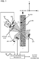
- FIG. 1 is a plan view illustrating the configuration of the measuring apparatus according to the first practical example.
- the measuring apparatus is configured as an apparatus for measuring a hematocrit value of blood by irradiating the blood that flows in a tubing 300, with light.
- the measuring apparatus is provided with an irradiator 100, a first light receiver 210, a second light receiver 220, a third light receiver 230, and a blood information processor 400.
- the irradiator 100 is configured, for example, as a laser light source, and is configured to irradiate the blood that flows in the tubing 300, with light.
- the irradiator 100 is placed such that an optical axis of irradiation light is an angle of ⁇ 1 to a direction in which the blood flows (i.e., a flow axis in FIG. 1 ).
- ⁇ 1 may be an angle other than the vicinity of 90 degrees and the vicinity of 45 degrees.
- the reason of avoiding setting ⁇ 1 in the vicinity of 90 degrees is to facilitate the placement of the third light receiver 230 described later.
- the reason of avoiding setting ⁇ 1 in the vicinity of 45 degrees is to prevent strong scattered light, which includes a backscatter component, from entering the third light receiver 230 described later.
- the first light receiver 210 is placed in a position in which it can receive a component that passes through the blood (i.e., a forward scatter component), out of light scattered by the blood that flows in the tubing 300. Specifically, the first light receiver 210 is placed in a position opposite to the irradiator 100, as viewed from the tubing 300. The first light receiver 210 is configured to output a signal corresponding to the received forward scatter component, to the blood information processor 400.
- a component that passes through the blood i.e., a forward scatter component
- the second light receiver 220 is placed in a position in which it can receive a component that is scattered in a direction of the position of the irradiator 100 (i.e., a backscatter component), out of the light scattered by the blood that flows in the tubing 300. Specifically, the second light receiver 220 is placed in a position extremely close to the irradiator 100. The second light receiver 220 is configured to output a signal corresponding to the received backscatter component, to the blood information processor 400.
- the third light receiver 230 is placed in a position in which it can receive a component that is scattered in a direction that is different from the direction of the position of the irradiator 100 (i.e., a side scatter component), out of the light scattered by the blood that flows in the tubing 300.
- the third light receiver 230 is placed in a direction at an angle of ⁇ 2 to the optical axis of irradiation light. ⁇ 2 is in the vicinity of 90 degrees.
- the blood information processor 400 is configured to arithmetically operate and output blood information (which is herein the hematocrit value of the blood), on the basis of the light receiving signals inputted from the first light receiver 210, the second light receiver 220, and the third light receiver 230. A method of arithmetically operating the blood information will be detailed later.
- FIG. 1 a positional relation of the light receivers is illustrated, two-dimensionally, but the light receivers may be arranged, three-dimensionally.
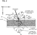
- FIG. 2 is version 1 of a cross sectional view illustrating a plurality of scatter components of the irradiation light and a placement location of each light receiver.
- FIG. 3 is version 2 of a cross sectional view illustrating a plurality of scatter components of irradiation light and a placement location of each light receiver.
- FIG. 2 is a cross sectional view in a direction in which the blood flows from a left side to a right side in the drawing.
- FIG. 3 is a cross sectional view in a direction in which the blood flows from a far side to a near side in the drawing.
- each of various components of the scattered light spreads from a scattering point (which is specifically a surface layer of the blood), three-dimensionally and radially.
- a scattering point which is specifically a surface layer of the blood
- the light receivers can receive the respective scatter components. This three-dimensional arrangement increases the degree of freedom of an arrangement layout of the light receivers.
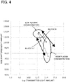
- FIG. 4 is a graph illustrating a relation between a transmitted light amount and a side scattered light amount.
- FIG. 5 is a graph illustrating a relation between the transmitted light amount and a backscattered light amount.
- a relation between an amount of light received by the first light receiver 210 (hereinafter referred to a "transmitted light amount” as occasion demands) and an amount of light received by the third light receiver 230 (hereinafter referred to a "side scattered light amount” as occasion demands) changes between when protein concentration in blood plasma in the blood is high and when it is low.
- a relation between a logarithm of the transmitted light amount (Log transmitted light amount) and the side scattered light amount linearly changes.
- a slope of a straight line varies depending on the type of the blood.
- a slope of a straight line of the blood A is clearly different from that of the blood B.
- a relation between the amount of the light received by the first light receiver 210 (i.e., the transmitted light amount) and an amount of light received by the second light receiver 220 (hereinafter referred to a "backscattered light amount" as occasion demands) also changes between when the protein concentration in the blood plasma in the blood is high and when it is low.
- a relation between the logarithm of the transmitted light amount (Log transmitted light amount) and the backscattered light amount linearly changes.
- a slope of a straight line varies depending on the type of the blood.
- a slope of a straight line of the blood A is clearly different from that of the blood B.
- the results in FIG. 4 and FIG. 5 may mean that the hematocrit value cannot be accurately measured from the transmitted light amount and the side scattered light amount, or from the transmitted light amount and the backscattered light amount.
- the measuring apparatus according to the first practical example is configured to calculate the hematocrit value by using the three types of scatter components.
- FIG. 6 is a graph illustrating a relation between the transmitted light amount and a sum of the side scattered light amount and the backscattered light amount (or an average value of the side scattered light amount and the backscattered light amount).
- the hematocrit value can be arithmetically operated by using the above relation.
- the hematocrit value may be arithmetically operated by using a predetermined mathematical expression, or may be determined by preparing a map as illustrated in FIG. 6 in advance.
- the transmitted light amount i.e., LogL1
- the transmitted light amount i.e., LogL1
- the transmitted light amount i.e., LogL1
- the transmitted light amount i.e., LogL1
- the transmitted light amount i.e., LogL1
- the sum of the side scattered light amount and the backscattered light amount i.e., ( ⁇ L2 + ⁇ L3)/2)
- the measuring apparatus in the first practical example, it is possible to arithmetically operate an accurate hematocrit value, by measuring each of the transmitted light amount (i.e., the forward scatter component of the scattered light), the side scattered light amount (i.e., the side scatter component of the scattered light), and the backscattered light amount (i.e., the backscatter component of the scattered light).
- the transmitted light amount i.e., the forward scatter component of the scattered light
- the side scattered light amount i.e., the side scatter component of the scattered light
- the backscattered light amount i.e., the backscatter component of the scattered light
- FIG. 7 is a plan view illustrating a configuration of the measuring apparatus according to the second practical example.
- the second practical example is partially different in configuration from the first practical example described above, and is substantially the same in other part.
- first practical example is partially different in configuration from the first practical example described above, and is substantially the same in other part.
- second practical example is partially different in configuration from the first practical example described above, and is substantially the same in other part.
- the measuring apparatus is provided with two irradiators (which are specifically a first irradiator 110 and a second irradiator 120).
- the first irradiator 110 is configured to apply light for measuring the transmitted light amount and the backscattered light amount.
- the first light receiver 210 which is configured to receive the forward scatter component, is placed opposite to the first irradiator 110, as viewed from the tubing 300, and the second light receiver 220, which is configured to receive the backscatter component, is placed extremely close to the first irradiator 110.
- the second irradiator 120 is configured to apply light for measuring the side scattered light amount.
- the second irradiator 120 is placed such that an optical axis of irradiation light is an angle of ⁇ 1 to a direction in which the blood flows (i.e., a flow axis).
- the third light receiver 230 is placed in a direction at an angle of ⁇ 2 to the optical axis of the light applied by the second irradiator 120.
- the provision of the two irradiators makes it possible to realize measurement conditions corresponding to the respective scatter components. Specifically, by placing the first irradiator 110 such that the light applied by the first irradiator 110 enters substantially perpendicular to the flow axis while diagonally setting the optical axis of the second irradiator 120 for measuring the side scattered light amount, it is possible to narrow a scattering range of the transmitted light, in comparison with that when the optical axis of the first irradiator 110 is diagonally set, so that it is possible to miniaturize the first irradiator 110.
- the present invention is not limited to the aforementioned embodiments and examples, but various changes may be made, if desired, without departing from the essence or spirit of the invention which can be read from the claims and the entire specification.
- a measuring apparatus, a measuring method, a computer program, and a recording medium that involve such changes are also intended to be within the technical scope of the present invention.
Landscapes
- Health & Medical Sciences (AREA)
- Life Sciences & Earth Sciences (AREA)
- Engineering & Computer Science (AREA)
- Chemical & Material Sciences (AREA)
- Physics & Mathematics (AREA)
- Biomedical Technology (AREA)
- General Health & Medical Sciences (AREA)
- General Physics & Mathematics (AREA)
- Immunology (AREA)
- Pathology (AREA)
- Biochemistry (AREA)
- Analytical Chemistry (AREA)
- Hematology (AREA)
- Ecology (AREA)
- Biophysics (AREA)
- Molecular Biology (AREA)
- Urology & Nephrology (AREA)
- Food Science & Technology (AREA)
- Medicinal Chemistry (AREA)
- Investigating Or Analysing Materials By Optical Means (AREA)
- Investigating Or Analysing Biological Materials (AREA)
Abstract
Description
- The present invention relates to a measuring apparatus and a measuring method that can measure information about fluid, a computer program, and a recording medium.
- For this type of apparatus, there is known an apparatus configured to irradiate fluid with light and to receive scattered light, thereby measuring information about the fluid. In the fluid, irradiation light is scattered in a plurality of directions. If those scattered lights are separately detected, it is considered that the information about the fluid can be measured by using respective properties of the scattered lights (e.g., refer to Patent Literature 1).
- Patent Literature 1: Japanese Patent No.
4451567 - The scattered light may include not only forward scattered light and backscattered light, but also side scattered light (i.e., light scattered in a direction substantially perpendicular to an optical axis in a surface layer of the fluid). A method of measuring the information about the fluid by using the side scattered light, however, still has room for improvement. For example, in a technology/technique described in the Patent Literature 1, a change in components of the fluid may also change a relation among scatter components. Thus, in the measurement of fluids having different components, measurement precision is significantly reduced, which is technically problematic.
- The above is an example of problems to be solved by the present invention. It is therefore an object of the present invention to provide a measuring apparatus and a measuring method that can measure the information about the fluid by using the side scattered light, a computer program, and a recording medium.
- The above object of the present invention can be achieved by a first measuring apparatus provided with: an irradiator configured to irradiate fluid with light; a first light receiver configured to receive a forward scatter component of scattered light scattered by the fluid; a second light receiver configured to receive a backscatter component of the scattered light; a third light receiver configured to receive a side scatter component of the scattered light; and an outputting device configured to output fluid information about the fluid, which is obtained on the basis of light receiving signals of the first light receiver, the second light receiver, and the third light receiver.
- The above object of the present invention can be achieved by a second measuring apparatus provided with: an irradiator configured to irradiate fluid with light; a first light receiver configured to receive a first component, which passes through the fluid, out of scattered light scattered by the fluid; a second light receiver configured to receive a second component, which is scattered in a first direction in which the irradiator is located in a surface layer of the fluid, out of the scattered light; a third light receiver configured to receive a third component, which is scattered in a second direction that is different from the first direction in the surface layer of the fluid, out of the scattered light; and an outputting device configured to output fluid information about the fluid, which is obtained on the basis of light receiving signals of the first light receiver, the second light receiver, and the third light receiver.
- The above object of the present invention can be achieved by a measuring method provided with: an irradiating process of irradiating fluid with light; a first light receiving process of receiving a forward scatter component of scattered light scattered by the fluid; a second light receiving process of receiving a backscatter component of the scattered light; a third light receiving process of receiving a side scatter component of the scattered light; and an outputting process of outputting fluid information about the fluid, which is obtained on the basis of light receiving signals of the first light receiving process, the second light receiving process, and the third light receiving process.
- The above object of the present invention can be achieved by a computer program for allowing a computer to perform: an irradiating process of irradiating fluid with light; a first light receiving process of receiving a forward scatter component of scattered light scattered by the fluid; a second light receiving process of receiving a backscatter component of the scattered light; a third light receiving process of receiving a side scatter component of the scattered light; and an outputting process of outputting fluid information about the fluid, which is obtained on the basis of light receiving signals of the first light receiving process, the second light receiving process, and the third light receiving process.
- The above object of the present invention can be achieved by a recording medium on which the computer program described above is recorded.
-
- [
FIG. 1] FIG. 1 is a plan view illustrating a configuration of a measuring apparatus according to a first practical example. - [
FIG. 2] FIG. 2 is version 1 of a cross sectional view illustrating a plurality of scatter components of irradiation light and a placement location of each light receiver. - [
FIG. 3] FIG. 3 isversion 2 of a cross sectional view illustrating a plurality of scatter components of irradiation light and a placement location of each light receiver. - [
FIG. 4] FIG. 4 is a graph illustrating a relation between a transmitted light amount and a side scattered light amount. - [
FIG. 5] FIG. 5 is a graph illustrating a relation between the transmitted light amount and a backscattered light amount. - [
FIG. 6] FIG. 6 is a graph illustrating a relation between the transmitted light amount and a sum of the side scattered light amount and the backscattered light amount. - [
FIG. 7] FIG. 7 is a plan view illustrating a configuration of a measuring apparatus according to a second practical example. -
- <1> A first measuring apparatus according to an embodiment is provided with: an irradiator configured to irradiate fluid with light; a first light receiver configured to receive a forward scatter component of scattered light scattered by the fluid; a second light receiver configured to receive a backscatter component of the scattered light; a third light receiver configured to receive a side scatter component of the scattered light; and an outputting device configured to output fluid information about the fluid, which is obtained on the basis of light receiving signals of the first light receiver, the second light receiver, and the third light receiver.
According to the first measuring apparatus in the embodiment, in operation thereof, for example, the fluid that flows in a tubing is irradiated with light by the irradiator. The light irradiated or applied from the irradiator is scattered in the fluid and becomes the scattered light.
The scattered light is received by each of the plurality of receivers arranged in different positions. Specifically, the forward scatter component of the scattered light is received by the first light receiver, the backscatter component of the scattered light is received by the second light receiver, and the side scatter component of the scattered light is received by the third light receiver. From the light receiving signals of the first light receiver, the second light receiver, and the third light receiver, the fluid information about the fluid is obtained, and is outputted from the outputting device.
In the embodiment, as described above, at least three scatter components (i.e., the forward scatter component, the backscatter component, and the side scatter component) are used to obtain the fluid information. It is thus possible to output accurate fluid information, in comparison with that when the fluid information is obtained on the basis of only one or two scatter components.
Moreover, an example of the fluid in the embodiment is blood, but the measurement can be also applied to any fluid other than the blood (e.g., ink, oil, wastewater or sewage, a seasoning, etc.).
Furthermore, an example of the fluid information in the embodiment may be information about the concentration of the fluid. More specifically, the fluid information may be information about a numerical value indicating a ratio of the volume of blood cells or blood corpuscles in the blood (which is a so-called hematocrit value). - <2> In an aspect of the measuring apparatus according to the embodiment, the outputting device is configured to output the fluid information, which is obtained on the basis of a sum of the backscatter component and the side scatter component, and on the basis of the forward scatter component.
According to studies by the present inventors, it is found that there is a fixed relation between the sum of the backscatter component and the side scatter component, and the forward scatter component. It is thus possible to output the accurate fluid information, more easily, by using the sum of the backscatter component and the side scatter component, and by using the forward scatter component. - <3> In another aspect of the measuring apparatus according to the embodiment, the irradiator is placed such that an optical axis of irradiation light is diagonal to a direction in which the fluid flows.
According to this aspect, since oblique light is applied with respect to the direction in which the fluid flows, it is easy to place the third light receiver configured to receive the side scatter component. It is also easy to detect a Doppler signal. - <4> In the aforementioned aspect in which the irradiator is placed such that the optical axis is diagonal, the irradiator may be placed such that the optical axis of the irradiation light is at an angle other than a vicinity of 45 degrees to the direction in which the fluid flows.
If the light is irradiated or applied at an angle of the vicinity of 45 degrees to the direction in which the fluid flows, strong scattered light, which includes the backscatter component, enters the third light receiver configured to receive the side scattered light, and it is hardly possible to appropriately receive the side scatter component. If the light is irradiated or applied at the angle other than the vicinity of 45 degrees, the aforementioned detrimental effect can be avoided. - <5> In another aspect of the measuring apparatus according to the embodiment, the irradiator includes a first irradiator and a second irradiator, the first light receiver is configured to receive a forward scatter component of scattered light of the first irradiator; the second light receiver is configured to receive a backscatter component of the scattered light of the first irradiator; and the third light receiver is configured to receive a side scatter component of scattered light of the second irradiator.
According to this aspect, the first irradiator for generating the forward scatter component and the backscatter component and the second irradiator for generating the side scatter component are provided, separately. Thus, in comparison with a single irradiator, it is possible to make measurements in the conditions that are suitable for the respective scatter components. - <6> A second measuring apparatus according to an embodiment is provided with: an irradiator configured to irradiate fluid with light; a first light receiver configured to receive a first component, which passes through the fluid, out of scattered light scattered by the fluid; a second light receiver configured to receive a second component, which is scattered in a first direction in which the irradiator is located in a surface layer of the fluid, out of the scattered light; a third light receiver configured to receive a third component, which is scattered in a second direction that is different from the first direction in the surface layer of the fluid, out of the scattered light; and an outputting device configured to output fluid information about the fluid, which is obtained on the basis of light receiving signals of the first light receiver, the second light receiver, and the third light receiver.
According to the second measuring apparatus in the embodiment, the first component, which passes through the fluid, is received by the first light receiver, the second component, which is scattered in the first direction in which the irradiator is located in the surface layer of the fluid, is received by the second light receiver, and the third component, which is scattered in the second direction that is different from the first direction in the surface layer of the fluid, is received by the third light receiver. From the light receiving signals of the first light receiver, the second light receiver, and the third light receiver, the fluid information about the fluid is obtained, and is outputted from the outputting device.
In the embodiment, as described above, at least three scatter components (i.e., the first component, the second component, and the third component) are used to obtain the fluid information. It is thus possible to output the accurate fluid information, in comparison with that when the fluid information is obtained on the basis of only one or two scatter components. - <7> A measuring method according to an embodiment is a measuring method provided with: an irradiating process of irradiating fluid with light; a first light receiving process of receiving a forward scatter component of scattered light scattered by the fluid; a second light receiving process of receiving a backscatter component of the scattered light; a third light receiving process of receiving a side scatter component of the scattered light; and an outputting process of outputting fluid information about the fluid, which is obtained on the basis of light receiving signals of the first light receiving process, the second light receiving process, and the third light receiving process.
According to the measuring method in the embodiment, as in the measuring apparatus described above, at least three scatter components are used to obtain the fluid information. It is thus possible to output the accurate fluid information, in comparison with that when the fluid information is obtained on the basis of only one or two scatter components. - <8> A computer program according to an embodiment allows a computer to perform: an irradiating process of irradiating fluid with light; a first light receiving process of receiving a forward scatter component of scattered light scattered by the fluid; a second light receiving process of receiving a backscatter component of the scattered light; a third light receiving process of receiving a side scatter component of the scattered light; and an outputting process of outputting fluid information about the fluid, which is obtained on the basis of light receiving signals of the first light receiving process, the second light receiving process, and the third light receiving process.
According to the computer program in the embodiment, the computer is allowed to perform the same processes as those in the measuring method described above. It is thus possible to output the accurate fluid information. - <9> On a recording medium according to an embodiment, the computer program described above is recorded.
- According to the recording medium in the embodiment, the stored computer program can be executed by the computer. It is thus possible to output the accurate fluid information.
- The effect and other benefits of the measuring apparatus, the measuring method, the computer program, and the recording medium according to the embodiments will be explained in more detail in practical examples below.
- Hereinafter, a measuring apparatus according to practical examples will be explained in detail with reference to the drawings. In the following, an explanation will be given to a situation in which the measuring apparatus is applied to an apparatus for measuring the concentration (or a hematocrit value) of blood that flows in a tubing that constitutes a blood circuit of an artificial dialysis apparatus.
- Firstly, a configuration of the measuring apparatus according to a first practical example will be explained with reference to
FIG. 1. FIG. 1 is a plan view illustrating the configuration of the measuring apparatus according to the first practical example. - As illustrated in
FIG. 1 , the measuring apparatus according to the first practical example is configured as an apparatus for measuring a hematocrit value of blood by irradiating the blood that flows in atubing 300, with light. The measuring apparatus is provided with anirradiator 100, afirst light receiver 210, a secondlight receiver 220, a thirdlight receiver 230, and ablood information processor 400. - The
irradiator 100 is configured, for example, as a laser light source, and is configured to irradiate the blood that flows in thetubing 300, with light. Theirradiator 100 is placed such that an optical axis of irradiation light is an angle of θ1 to a direction in which the blood flows (i.e., a flow axis inFIG. 1 ). θ1 may be an angle other than the vicinity of 90 degrees and the vicinity of 45 degrees. The reason of avoiding setting θ1 in the vicinity of 90 degrees is to facilitate the placement of the thirdlight receiver 230 described later. The reason of avoiding setting θ1 in the vicinity of 45 degrees is to prevent strong scattered light, which includes a backscatter component, from entering the thirdlight receiver 230 described later. - The
first light receiver 210 is placed in a position in which it can receive a component that passes through the blood (i.e., a forward scatter component), out of light scattered by the blood that flows in thetubing 300. Specifically, thefirst light receiver 210 is placed in a position opposite to theirradiator 100, as viewed from thetubing 300. Thefirst light receiver 210 is configured to output a signal corresponding to the received forward scatter component, to theblood information processor 400. - The second
light receiver 220 is placed in a position in which it can receive a component that is scattered in a direction of the position of the irradiator 100 (i.e., a backscatter component), out of the light scattered by the blood that flows in thetubing 300. Specifically, the secondlight receiver 220 is placed in a position extremely close to theirradiator 100. The secondlight receiver 220 is configured to output a signal corresponding to the received backscatter component, to theblood information processor 400. - The third
light receiver 230 is placed in a position in which it can receive a component that is scattered in a direction that is different from the direction of the position of the irradiator 100 (i.e., a side scatter component), out of the light scattered by the blood that flows in thetubing 300. Specifically, the thirdlight receiver 230 is placed in a direction at an angle of θ2 to the optical axis of irradiation light. θ2 is in the vicinity of 90 degrees. - The
blood information processor 400 is configured to arithmetically operate and output blood information (which is herein the hematocrit value of the blood), on the basis of the light receiving signals inputted from thefirst light receiver 210, the secondlight receiver 220, and the thirdlight receiver 230. A method of arithmetically operating the blood information will be detailed later. - For convenience of explanation, in
FIG. 1 , a positional relation of the light receivers is illustrated, two-dimensionally, but the light receivers may be arranged, three-dimensionally. Hereinafter, a three-dimensional arrangement of thefirst light receiver 210, the secondlight receiver 220, and the thirdlight receiver 230 will be explained with reference toFIG. 2 andFIG. 3 .FIG. 2 is version 1 of a cross sectional view illustrating a plurality of scatter components of the irradiation light and a placement location of each light receiver.FIG. 3 isversion 2 of a cross sectional view illustrating a plurality of scatter components of irradiation light and a placement location of each light receiver. - Each of coordinate axes in
FIG. 2 andFIG. 3 corresponds to a coordinate axis inFIG. 1 . In other words,FIG. 2 is a cross sectional view in a direction in which the blood flows from a left side to a right side in the drawing.FIG. 3 is a cross sectional view in a direction in which the blood flows from a far side to a near side in the drawing. - As illustrated in
FIG. 2 andFIG. 3 , each of various components of the scattered light (i.e., the forward scatter component, the backscatter component, and the side scatter component) spreads from a scattering point (which is specifically a surface layer of the blood), three-dimensionally and radially. Thus, even when thefirst light receiver 210, the secondlight receiver 220, and the thirdlight receiver 230 are arranged, three-dimensionally, as illustrated inFIG. 2 andFIG. 3 , the light receivers can receive the respective scatter components. This three-dimensional arrangement increases the degree of freedom of an arrangement layout of the light receivers. - Next, a relation among the scatter components and a resulting problem thereof will be explained with reference to
FIG. 4 andFIG. 5 .FIG. 4 is a graph illustrating a relation between a transmitted light amount and a side scattered light amount.FIG. 5 is a graph illustrating a relation between the transmitted light amount and a backscattered light amount. - As illustrated in
FIG. 4 , a relation between an amount of light received by the first light receiver 210 (hereinafter referred to a "transmitted light amount" as occasion demands) and an amount of light received by the third light receiver 230 (hereinafter referred to a "side scattered light amount" as occasion demands) changes between when protein concentration in blood plasma in the blood is high and when it is low. Specifically, when the protein concentration in the blood plasma changes, a relation between a logarithm of the transmitted light amount (Log transmitted light amount) and the side scattered light amount linearly changes. At this time, a slope of a straight line varies depending on the type of the blood. As is clear from the drawing, a slope of a straight line of the blood A is clearly different from that of the blood B. - As illustrated in
FIG. 5 , a relation between the amount of the light received by the first light receiver 210 (i.e., the transmitted light amount) and an amount of light received by the second light receiver 220 (hereinafter referred to a "backscattered light amount" as occasion demands) also changes between when the protein concentration in the blood plasma in the blood is high and when it is low. Specifically, when the protein concentration in the blood plasma changes, a relation between the logarithm of the transmitted light amount (Log transmitted light amount) and the backscattered light amount linearly changes. At this time, a slope of a straight line varies depending on the type of the blood. As is clear from the drawing, a slope of a straight line of the blood A is clearly different from that of the blood B. - The results in
FIG. 4 andFIG. 5 may mean that the hematocrit value cannot be accurately measured from the transmitted light amount and the side scattered light amount, or from the transmitted light amount and the backscattered light amount. In order to solve the problem, the measuring apparatus according to the first practical example is configured to calculate the hematocrit value by using the three types of scatter components. - Next, a method of deriving the hematocrit value by the measuring apparatus according to the first practical example will be explained with reference to
FIG. 6. FIG. 6 is a graph illustrating a relation between the transmitted light amount and a sum of the side scattered light amount and the backscattered light amount (or an average value of the side scattered light amount and the backscattered light amount). - As illustrated in
FIG. 6 , according to studies by the present inventors, it is found that there is a fixed relation between the transmitted light amount and the sum of the side scattered light amount and the backscattered light amount. Specifically, when the transmitted light amount is L1, the side scattered light amount is L2, and the backscattered light amount, the following relation is established.
- As a result, by measuring each of the transmitted light amount, the side scattered light amount, and the backscattered light amount, the hematocrit value can be arithmetically operated by using the above relation. The hematocrit value may be arithmetically operated by using a predetermined mathematical expression, or may be determined by preparing a map as illustrated in
FIG. 6 in advance. - For example, when the transmitted light amount (i.e., LogL1) is A, if the sum of the side scattered light amount and the backscattered light amount (i.e., (α×L2 + β×L3)/2) is a, then, the hematocrit value can be determined to be Hct=50. When the transmitted light amount (i.e., LogL1) is A, if the sum of the side scattered light amount and the backscattered light amount (i.e., (α×L2 + β×L3)/2) is b, then, the hematocrit value can be determined to be Hct=40.
- As explained above, according to the measuring apparatus in the first practical example, it is possible to arithmetically operate an accurate hematocrit value, by measuring each of the transmitted light amount (i.e., the forward scatter component of the scattered light), the side scattered light amount (i.e., the side scatter component of the scattered light), and the backscattered light amount (i.e., the backscatter component of the scattered light).
- Next, a measuring apparatus according to a second practical example will be explained with reference to
FIG. 7. FIG. 7 is a plan view illustrating a configuration of the measuring apparatus according to the second practical example. - The second practical example is partially different in configuration from the first practical example described above, and is substantially the same in other part. Thus, hereinafter, only a different part from the first practical example will be explained in detail, and an explanation of the same part will be omitted, as occasion demands.
- As illustrated in
FIG. 7 , the measuring apparatus according to the second practical example is provided with two irradiators (which are specifically afirst irradiator 110 and a second irradiator 120). - The
first irradiator 110 is configured to apply light for measuring the transmitted light amount and the backscattered light amount. Thus, thefirst light receiver 210, which is configured to receive the forward scatter component, is placed opposite to thefirst irradiator 110, as viewed from thetubing 300, and the secondlight receiver 220, which is configured to receive the backscatter component, is placed extremely close to thefirst irradiator 110. - The
second irradiator 120 is configured to apply light for measuring the side scattered light amount. Thus, thesecond irradiator 120 is placed such that an optical axis of irradiation light is an angle of θ1 to a direction in which the blood flows (i.e., a flow axis). Moreover, the thirdlight receiver 230 is placed in a direction at an angle of θ2 to the optical axis of the light applied by thesecond irradiator 120. - According to the measuring apparatus in the second practical example, the provision of the two irradiators makes it possible to realize measurement conditions corresponding to the respective scatter components. Specifically, by placing the
first irradiator 110 such that the light applied by thefirst irradiator 110 enters substantially perpendicular to the flow axis while diagonally setting the optical axis of thesecond irradiator 120 for measuring the side scattered light amount, it is possible to narrow a scattering range of the transmitted light, in comparison with that when the optical axis of thefirst irradiator 110 is diagonally set, so that it is possible to miniaturize thefirst irradiator 110. - The present invention is not limited to the aforementioned embodiments and examples, but various changes may be made, if desired, without departing from the essence or spirit of the invention which can be read from the claims and the entire specification. A measuring apparatus, a measuring method, a computer program, and a recording medium that involve such changes are also intended to be within the technical scope of the present invention.
-
- 100
- irradiator
- 110
- first irradiator
- 120
- second irradiator
- 210
- first light receiver
- 220
- second light receiver
- 230
- third light receiver
- 300
- tubing
- 400
- blood information processor
Claims (9)
- A measuring apparatus comprising:an irradiator configured to irradiate fluid with light;a first light receiver configured to receive a forward scatter component of scattered light scattered by the fluid;a second light receiver configured to receive a backscatter component of the scattered light;a third light receiver configured to receive a side scatter component of the scattered light; andan outputting device configured to output fluid information about the fluid, which is obtained on the basis of light receiving signals of said first light receiver, said second light receiver, and said third light receiver.
- The measuring apparatus according to claim 1, wherein said outputting device is configured to output the fluid information, which is obtained on the basis of a sum of the backscatter component and the side scatter component, and on the basis of the forward scatter component.
- The measuring apparatus according to claim 1 or 2, wherein said irradiator is placed such that an optical axis of irradiation light is diagonal to a direction in which the fluid flows.
- The measuring apparatus according to claim 3, wherein said irradiator is placed such that the optical axis of the irradiation light is at an angle other than a vicinity of 45 degrees to the direction in which the fluid flows.
- The measuring apparatus according to any of claims 1 to 4, wherein
said irradiator includes a first irradiator and a second irradiator,
said first light receiver is configured to receive a forward scatter component of scattered light of the first irradiator;
said second light receiver is configured to receive a backscatter component of the scattered light of the first irradiator; and
said third light receiver is configured to receive a side scatter component of scattered light of the second irradiator. - A measuring apparatus comprising:an irradiator configured to irradiate fluid with light;a first light receiver configured to receive a first component, which passes through the fluid, out of scattered light scattered by the fluid;a second light receiver configured to receive a second component, which is scattered in a first direction in which said irradiator is located in a surface layer of the fluid, out of the scattered light;a third light receiver configured to receive a third component, which is scattered in a second direction that is different from the first direction in the surface layer of the fluid, out of the scattered light; andan outputting device configured to output fluid information about the fluid, which is obtained on the basis of light receiving signals of said first light receiver, said second light receiver, and said third light receiver.
- A measuring method comprising:an irradiating process of irradiating fluid with light;a first light receiving process of receiving a forward scatter component of scattered light scattered by the fluid;a second light receiving process of receiving a backscatter component of the scattered light;a third light receiving process of receiving a side scatter component of the scattered light; andan outputting process of outputting fluid information about the fluid, which is obtained on the basis of light receiving signals of said first light receiving process, said second light receiving process, and said third light receiving process.
- A computer program for allowing a computer to perform:an irradiating process of irradiating fluid with light;a first light receiving process of receiving a forward scatter component of scattered light scattered by the fluid;a second light receiving process of receiving a backscatter component of the scattered light;a third light receiving process of receiving a side scatter component of the scattered light; andan outputting process of outputting fluid information about the fluid, which is obtained on the basis of light receiving signals of said first light receiving process, said second light receiving process, and said third light receiving process.
- A recording medium on which the computer program according to claim 8 is recorded.
Applications Claiming Priority (1)
| Application Number | Priority Date | Filing Date | Title |
|---|---|---|---|
| PCT/JP2017/035678 WO2019064559A1 (en) | 2017-09-29 | 2017-09-29 | Measurement device, measurement method, computer program, and storage medium |
Publications (3)
| Publication Number | Publication Date |
|---|---|
| EP3690425A1 true EP3690425A1 (en) | 2020-08-05 |
| EP3690425A4 EP3690425A4 (en) | 2021-05-19 |
| EP3690425B1 EP3690425B1 (en) | 2023-07-19 |
Family
ID=65902502
Family Applications (1)
| Application Number | Title | Priority Date | Filing Date |
|---|---|---|---|
| EP17927545.8A Active EP3690425B1 (en) | 2017-09-29 | 2017-09-29 | Measurement device and measurement method for hematoctrit |
Country Status (4)
| Country | Link |
|---|---|
| US (1) | US11209359B2 (en) |
| EP (1) | EP3690425B1 (en) |
| JP (1) | JP6858875B2 (en) |
| WO (1) | WO2019064559A1 (en) |
Families Citing this family (1)
| Publication number | Priority date | Publication date | Assignee | Title |
|---|---|---|---|---|
| CN111366514A (en) * | 2020-04-24 | 2020-07-03 | 南京波瑞自动化科技有限公司 | A system for measuring smoke and dust and its realization method |
Family Cites Families (21)
| Publication number | Priority date | Publication date | Assignee | Title |
|---|---|---|---|---|
| JP2815435B2 (en) * | 1989-12-22 | 1998-10-27 | 株式会社日立製作所 | Particle analyzer and blood cell counter |
| US5506679A (en) * | 1994-09-08 | 1996-04-09 | Hach Company | Nephelometer instrument |
| JP3446410B2 (en) * | 1995-07-24 | 2003-09-16 | 株式会社島津製作所 | Laser diffraction particle size distribution analyzer |
| JP3371816B2 (en) * | 1998-07-31 | 2003-01-27 | 株式会社島津製作所 | Particle concentration measuring method and device and particle measuring device |
| SE9804142D0 (en) | 1998-11-30 | 1998-11-30 | Gambro Ab | Method and device for providing a signal |
| US6519034B1 (en) * | 1998-12-16 | 2003-02-11 | Honeywell International Inc. | Oil quality sensor |
| US6567166B2 (en) | 2001-02-21 | 2003-05-20 | Honeywell International Inc. | Focused laser light turbidity sensor |
| US6743634B2 (en) * | 2002-08-23 | 2004-06-01 | Coulter International Corp. | Method and apparatus for differentiating blood cells using back-scatter |
| US6798508B2 (en) * | 2002-08-23 | 2004-09-28 | Coulter International Corp. | Fiber optic apparatus for detecting light scatter to differentiate blood cells and the like |
| DE10330641A1 (en) | 2003-07-07 | 2005-02-03 | Basf Coatings Ag | High-precision remission sensor for wet measurement of paints and pigment pastes |
| EP1754057A1 (en) | 2004-05-25 | 2007-02-21 | Renner Herrmann S.A. | An apparatus and method for measuring the spectral properties of a fluid |
| US7390662B2 (en) * | 2005-11-09 | 2008-06-24 | Beckman Coulter, Inc. | Method and apparatus for performing platelet measurement |
| DE102006029899B4 (en) * | 2006-06-29 | 2009-06-04 | Fresenius Medical Care Deutschland Gmbh | Spectroscopic detector and method for the determination of blood and biological markers in liquids |
| CN102282453B (en) * | 2008-11-14 | 2013-08-14 | 贝克曼考尔特公司 | Monolithic optical flow cells and method of manufacture |
| DE102009017304A1 (en) | 2009-04-11 | 2010-10-21 | Fresenius Medical Care Deutschland Gmbh | Apparatus and method for measuring a blood component in blood for an extracorporeal blood treatment device |
| US7973923B2 (en) * | 2009-04-27 | 2011-07-05 | Endress+Hauser Conducta Inc. | Multi-port inline flow cell for use in monitoring multiple parameters in a sanitary process line |
| US9304122B2 (en) | 2012-02-04 | 2016-04-05 | Centre For Cellular And Molecular Platforms (C-Camp) | Microfluidic-based flow analyzer |
| US9372143B2 (en) * | 2013-05-15 | 2016-06-21 | Captl Llc | Scanning image flow cytometer |
| DE102013018284B4 (en) | 2013-10-31 | 2015-08-27 | Fresenius Medical Care Deutschland Gmbh | Method and device for detecting hemolysis or for determining a correction factor which corrects the influence of hemolysis on a measurement of the hematocrit |
| MX2019002911A (en) * | 2016-09-13 | 2019-07-18 | Basf Coatings Gmbh | Sensor for a virtually simultaneous measurement of a transmission and/or forward scattering and/or remission and for a simultaneous measurement of the transmission and forward scattering or transmission and remission of a liquid sample. |
| IT201700073456A1 (en) * | 2017-06-30 | 2018-12-30 | Eos S R L | Method for characterization of objects by analysis of diffuse radiation and related instrumentation. |
-
2017
- 2017-09-29 US US16/651,563 patent/US11209359B2/en active Active
- 2017-09-29 JP JP2019544157A patent/JP6858875B2/en active Active
- 2017-09-29 EP EP17927545.8A patent/EP3690425B1/en active Active
- 2017-09-29 WO PCT/JP2017/035678 patent/WO2019064559A1/en not_active Ceased
Also Published As
| Publication number | Publication date |
|---|---|
| US20200264100A1 (en) | 2020-08-20 |
| EP3690425B1 (en) | 2023-07-19 |
| WO2019064559A1 (en) | 2019-04-04 |
| US11209359B2 (en) | 2021-12-28 |
| EP3690425A4 (en) | 2021-05-19 |
| JPWO2019064559A1 (en) | 2020-10-15 |
| JP6858875B2 (en) | 2021-04-14 |
Similar Documents
| Publication | Publication Date | Title |
|---|---|---|
| EP3803330A1 (en) | Analysis apparatus and method for analyzing a viscosity of a fluid | |
| JP5259318B2 (en) | Analytical system for measuring analytes in body fluids | |
| CN113227759B (en) | Size distribution measuring device, size distribution measuring method, and sample container | |
| JP6604611B2 (en) | Non-invasive biological lipid measuring instrument and non-invasive biological lipid measuring method | |
| JP2019512701A (en) | Particle characterization | |
| CN101153858A (en) | Method for detecting erroneous measurements obtained with ion-selective electrodes | |
| EP3330367A1 (en) | Cell analysis apparatus using plurality of lasers | |
| JP7101418B2 (en) | Methods for light scattering detectors and light scattering detectors | |
| KR20210104733A (en) | Methods and apparatus for determining the flow rate and/or concentration of particles in a fluid | |
| EP3165902A1 (en) | A method and a sensor for measuring suspended solids in a liquid | |
| US11209359B2 (en) | Apparatus and method for measuring fluid information from light scattering | |
| JP6880059B2 (en) | Program for particle size distribution measuring device and particle size distribution measuring device | |
| Schwarz et al. | Investigations on the capability of the statistical extinction method for the determination of mean particle sizes in concentrated particle systems | |
| Oris et al. | Method validation of a set of 12 GEM® Premier™ 4000 blood gas analyzers for point-of-care testing in a university teaching hospital | |
| Batista et al. | Advancing calibration techniques for accurate micro and nanoflow measurements | |
| JP2010243374A (en) | Nanoparticle size measuring apparatus and nanoparticle size measuring method | |
| JP7285503B2 (en) | TOTAL PROTEIN MEASUREMENT DEVICE AND TOTAL PROTEIN MEASUREMENT METHOD | |
| JP7175435B2 (en) | Flow velocity identification device | |
| JPS61294335A (en) | Particle analysis device | |
| Berthe et al. | Three-dimensional, three-component wall-PIV | |
| JP6872557B2 (en) | Program for particle size distribution measuring device and particle size distribution measuring device | |
| WO2015151240A1 (en) | Analysis method and analysis device for detection of abnormal analyte | |
| Guthrie et al. | The Ultra‐Flo 100 platelet counter: a new approach to platelet counting | |
| JP2004257919A (en) | Grain size distribution measuring device | |
| FI97644C (en) | Procedure for refractometer measurement |
Legal Events
| Date | Code | Title | Description |
|---|---|---|---|
| STAA | Information on the status of an ep patent application or granted ep patent |
Free format text: STATUS: THE INTERNATIONAL PUBLICATION HAS BEEN MADE |
|
| PUAI | Public reference made under article 153(3) epc to a published international application that has entered the european phase |
Free format text: ORIGINAL CODE: 0009012 |
|
| STAA | Information on the status of an ep patent application or granted ep patent |
Free format text: STATUS: REQUEST FOR EXAMINATION WAS MADE |
|
| 17P | Request for examination filed |
Effective date: 20200325 |
|
| AK | Designated contracting states |
Kind code of ref document: A1 Designated state(s): AL AT BE BG CH CY CZ DE DK EE ES FI FR GB GR HR HU IE IS IT LI LT LU LV MC MK MT NL NO PL PT RO RS SE SI SK SM TR |
|
| AX | Request for extension of the european patent |
Extension state: BA ME |
|
| DAV | Request for validation of the european patent (deleted) | ||
| DAX | Request for extension of the european patent (deleted) | ||
| REG | Reference to a national code |
Ref country code: DE Ref legal event code: R079 Free format text: PREVIOUS MAIN CLASS: G01N0021490000 Ipc: G01N0021530000 Ref country code: DE Ref legal event code: R079 Ref document number: 602017071664 Country of ref document: DE Free format text: PREVIOUS MAIN CLASS: G01N0021490000 Ipc: G01N0021530000 |
|
| A4 | Supplementary search report drawn up and despatched |
Effective date: 20210421 |
|
| RIC1 | Information provided on ipc code assigned before grant |
Ipc: G01N 21/53 20060101AFI20210415BHEP Ipc: G01N 33/487 20060101ALI20210415BHEP |
|
| RAP1 | Party data changed (applicant data changed or rights of an application transferred) |
Owner name: NIKKISO COMPANY LIMITED Owner name: AIR WATER BIODESIGN INC. |
|
| GRAP | Despatch of communication of intention to grant a patent |
Free format text: ORIGINAL CODE: EPIDOSNIGR1 |
|
| STAA | Information on the status of an ep patent application or granted ep patent |
Free format text: STATUS: GRANT OF PATENT IS INTENDED |
|
| INTG | Intention to grant announced |
Effective date: 20230214 |
|
| GRAS | Grant fee paid |
Free format text: ORIGINAL CODE: EPIDOSNIGR3 |
|
| P01 | Opt-out of the competence of the unified patent court (upc) registered |
Effective date: 20230414 |
|
| GRAA | (expected) grant |
Free format text: ORIGINAL CODE: 0009210 |
|
| STAA | Information on the status of an ep patent application or granted ep patent |
Free format text: STATUS: THE PATENT HAS BEEN GRANTED |
|
| AK | Designated contracting states |
Kind code of ref document: B1 Designated state(s): AL AT BE BG CH CY CZ DE DK EE ES FI FR GB GR HR HU IE IS IT LI LT LU LV MC MK MT NL NO PL PT RO RS SE SI SK SM TR |
|
| REG | Reference to a national code |
Ref country code: GB Ref legal event code: FG4D |
|
| REG | Reference to a national code |
Ref country code: CH Ref legal event code: EP |
|
| REG | Reference to a national code |
Ref country code: DE Ref legal event code: R096 Ref document number: 602017071664 Country of ref document: DE |
|
| REG | Reference to a national code |
Ref country code: IE Ref legal event code: FG4D |
|
| REG | Reference to a national code |
Ref country code: SE Ref legal event code: TRGR |
|
| REG | Reference to a national code |
Ref country code: LT Ref legal event code: MG9D |
|
| REG | Reference to a national code |
Ref country code: NL Ref legal event code: MP Effective date: 20230719 |
|
| REG | Reference to a national code |
Ref country code: AT Ref legal event code: MK05 Ref document number: 1589938 Country of ref document: AT Kind code of ref document: T Effective date: 20230719 |
|
| PG25 | Lapsed in a contracting state [announced via postgrant information from national office to epo] |
Ref country code: NL Free format text: LAPSE BECAUSE OF FAILURE TO SUBMIT A TRANSLATION OF THE DESCRIPTION OR TO PAY THE FEE WITHIN THE PRESCRIBED TIME-LIMIT Effective date: 20230719 |
|
| PG25 | Lapsed in a contracting state [announced via postgrant information from national office to epo] |
Ref country code: GR Free format text: LAPSE BECAUSE OF FAILURE TO SUBMIT A TRANSLATION OF THE DESCRIPTION OR TO PAY THE FEE WITHIN THE PRESCRIBED TIME-LIMIT Effective date: 20231020 |
|
| PG25 | Lapsed in a contracting state [announced via postgrant information from national office to epo] |
Ref country code: IS Free format text: LAPSE BECAUSE OF FAILURE TO SUBMIT A TRANSLATION OF THE DESCRIPTION OR TO PAY THE FEE WITHIN THE PRESCRIBED TIME-LIMIT Effective date: 20231119 |
|
| PG25 | Lapsed in a contracting state [announced via postgrant information from national office to epo] |
Ref country code: RS Free format text: LAPSE BECAUSE OF FAILURE TO SUBMIT A TRANSLATION OF THE DESCRIPTION OR TO PAY THE FEE WITHIN THE PRESCRIBED TIME-LIMIT Effective date: 20230719 Ref country code: PT Free format text: LAPSE BECAUSE OF FAILURE TO SUBMIT A TRANSLATION OF THE DESCRIPTION OR TO PAY THE FEE WITHIN THE PRESCRIBED TIME-LIMIT Effective date: 20231120 Ref country code: NO Free format text: LAPSE BECAUSE OF FAILURE TO SUBMIT A TRANSLATION OF THE DESCRIPTION OR TO PAY THE FEE WITHIN THE PRESCRIBED TIME-LIMIT Effective date: 20231019 Ref country code: LV Free format text: LAPSE BECAUSE OF FAILURE TO SUBMIT A TRANSLATION OF THE DESCRIPTION OR TO PAY THE FEE WITHIN THE PRESCRIBED TIME-LIMIT Effective date: 20230719 Ref country code: LT Free format text: LAPSE BECAUSE OF FAILURE TO SUBMIT A TRANSLATION OF THE DESCRIPTION OR TO PAY THE FEE WITHIN THE PRESCRIBED TIME-LIMIT Effective date: 20230719 Ref country code: IS Free format text: LAPSE BECAUSE OF FAILURE TO SUBMIT A TRANSLATION OF THE DESCRIPTION OR TO PAY THE FEE WITHIN THE PRESCRIBED TIME-LIMIT Effective date: 20231119 Ref country code: HR Free format text: LAPSE BECAUSE OF FAILURE TO SUBMIT A TRANSLATION OF THE DESCRIPTION OR TO PAY THE FEE WITHIN THE PRESCRIBED TIME-LIMIT Effective date: 20230719 Ref country code: GR Free format text: LAPSE BECAUSE OF FAILURE TO SUBMIT A TRANSLATION OF THE DESCRIPTION OR TO PAY THE FEE WITHIN THE PRESCRIBED TIME-LIMIT Effective date: 20231020 Ref country code: FI Free format text: LAPSE BECAUSE OF FAILURE TO SUBMIT A TRANSLATION OF THE DESCRIPTION OR TO PAY THE FEE WITHIN THE PRESCRIBED TIME-LIMIT Effective date: 20230719 Ref country code: AT Free format text: LAPSE BECAUSE OF FAILURE TO SUBMIT A TRANSLATION OF THE DESCRIPTION OR TO PAY THE FEE WITHIN THE PRESCRIBED TIME-LIMIT Effective date: 20230719 |
|
| PG25 | Lapsed in a contracting state [announced via postgrant information from national office to epo] |
Ref country code: PL Free format text: LAPSE BECAUSE OF FAILURE TO SUBMIT A TRANSLATION OF THE DESCRIPTION OR TO PAY THE FEE WITHIN THE PRESCRIBED TIME-LIMIT Effective date: 20230719 |
|
| REG | Reference to a national code |
Ref country code: DE Ref legal event code: R097 Ref document number: 602017071664 Country of ref document: DE |
|
| PG25 | Lapsed in a contracting state [announced via postgrant information from national office to epo] |
Ref country code: ES Free format text: LAPSE BECAUSE OF FAILURE TO SUBMIT A TRANSLATION OF THE DESCRIPTION OR TO PAY THE FEE WITHIN THE PRESCRIBED TIME-LIMIT Effective date: 20230719 |
|
| PG25 | Lapsed in a contracting state [announced via postgrant information from national office to epo] |
Ref country code: SM Free format text: LAPSE BECAUSE OF FAILURE TO SUBMIT A TRANSLATION OF THE DESCRIPTION OR TO PAY THE FEE WITHIN THE PRESCRIBED TIME-LIMIT Effective date: 20230719 Ref country code: RO Free format text: LAPSE BECAUSE OF FAILURE TO SUBMIT A TRANSLATION OF THE DESCRIPTION OR TO PAY THE FEE WITHIN THE PRESCRIBED TIME-LIMIT Effective date: 20230719 Ref country code: ES Free format text: LAPSE BECAUSE OF FAILURE TO SUBMIT A TRANSLATION OF THE DESCRIPTION OR TO PAY THE FEE WITHIN THE PRESCRIBED TIME-LIMIT Effective date: 20230719 Ref country code: EE Free format text: LAPSE BECAUSE OF FAILURE TO SUBMIT A TRANSLATION OF THE DESCRIPTION OR TO PAY THE FEE WITHIN THE PRESCRIBED TIME-LIMIT Effective date: 20230719 Ref country code: DK Free format text: LAPSE BECAUSE OF FAILURE TO SUBMIT A TRANSLATION OF THE DESCRIPTION OR TO PAY THE FEE WITHIN THE PRESCRIBED TIME-LIMIT Effective date: 20230719 Ref country code: CZ Free format text: LAPSE BECAUSE OF FAILURE TO SUBMIT A TRANSLATION OF THE DESCRIPTION OR TO PAY THE FEE WITHIN THE PRESCRIBED TIME-LIMIT Effective date: 20230719 Ref country code: SK Free format text: LAPSE BECAUSE OF FAILURE TO SUBMIT A TRANSLATION OF THE DESCRIPTION OR TO PAY THE FEE WITHIN THE PRESCRIBED TIME-LIMIT Effective date: 20230719 |
|
| REG | Reference to a national code |
Ref country code: CH Ref legal event code: PL |
|
| PG25 | Lapsed in a contracting state [announced via postgrant information from national office to epo] |
Ref country code: LU Free format text: LAPSE BECAUSE OF NON-PAYMENT OF DUE FEES Effective date: 20230929 |
|
| PLBE | No opposition filed within time limit |
Free format text: ORIGINAL CODE: 0009261 |
|
| STAA | Information on the status of an ep patent application or granted ep patent |
Free format text: STATUS: NO OPPOSITION FILED WITHIN TIME LIMIT |
|
| REG | Reference to a national code |
Ref country code: BE Ref legal event code: MM Effective date: 20230930 |
|
| PG25 | Lapsed in a contracting state [announced via postgrant information from national office to epo] |
Ref country code: LU Free format text: LAPSE BECAUSE OF NON-PAYMENT OF DUE FEES Effective date: 20230929 Ref country code: MC Free format text: LAPSE BECAUSE OF FAILURE TO SUBMIT A TRANSLATION OF THE DESCRIPTION OR TO PAY THE FEE WITHIN THE PRESCRIBED TIME-LIMIT Effective date: 20230719 |
|
| 26N | No opposition filed |
Effective date: 20240422 |
|
| REG | Reference to a national code |
Ref country code: IE Ref legal event code: MM4A |
|
| PG25 | Lapsed in a contracting state [announced via postgrant information from national office to epo] |
Ref country code: IE Free format text: LAPSE BECAUSE OF NON-PAYMENT OF DUE FEES Effective date: 20230929 |
|
| PG25 | Lapsed in a contracting state [announced via postgrant information from national office to epo] |
Ref country code: CH Free format text: LAPSE BECAUSE OF NON-PAYMENT OF DUE FEES Effective date: 20230930 |
|
| REG | Reference to a national code |
Ref country code: SE Ref legal event code: RPOT |
|
| PG25 | Lapsed in a contracting state [announced via postgrant information from national office to epo] |
Ref country code: IE Free format text: LAPSE BECAUSE OF NON-PAYMENT OF DUE FEES Effective date: 20230929 Ref country code: CH Free format text: LAPSE BECAUSE OF NON-PAYMENT OF DUE FEES Effective date: 20230930 Ref country code: SI Free format text: LAPSE BECAUSE OF FAILURE TO SUBMIT A TRANSLATION OF THE DESCRIPTION OR TO PAY THE FEE WITHIN THE PRESCRIBED TIME-LIMIT Effective date: 20230719 |
|
| PG25 | Lapsed in a contracting state [announced via postgrant information from national office to epo] |
Ref country code: BE Free format text: LAPSE BECAUSE OF NON-PAYMENT OF DUE FEES Effective date: 20230930 |
|
| PG25 | Lapsed in a contracting state [announced via postgrant information from national office to epo] |
Ref country code: BG Free format text: LAPSE BECAUSE OF FAILURE TO SUBMIT A TRANSLATION OF THE DESCRIPTION OR TO PAY THE FEE WITHIN THE PRESCRIBED TIME-LIMIT Effective date: 20230719 |
|
| PG25 | Lapsed in a contracting state [announced via postgrant information from national office to epo] |
Ref country code: BG Free format text: LAPSE BECAUSE OF FAILURE TO SUBMIT A TRANSLATION OF THE DESCRIPTION OR TO PAY THE FEE WITHIN THE PRESCRIBED TIME-LIMIT Effective date: 20230719 |
|
| PG25 | Lapsed in a contracting state [announced via postgrant information from national office to epo] |
Ref country code: CY Free format text: LAPSE BECAUSE OF FAILURE TO SUBMIT A TRANSLATION OF THE DESCRIPTION OR TO PAY THE FEE WITHIN THE PRESCRIBED TIME-LIMIT; INVALID AB INITIO Effective date: 20170929 |
|
| PG25 | Lapsed in a contracting state [announced via postgrant information from national office to epo] |
Ref country code: HU Free format text: LAPSE BECAUSE OF FAILURE TO SUBMIT A TRANSLATION OF THE DESCRIPTION OR TO PAY THE FEE WITHIN THE PRESCRIBED TIME-LIMIT; INVALID AB INITIO Effective date: 20170929 |
|
| PGFP | Annual fee paid to national office [announced via postgrant information from national office to epo] |
Ref country code: DE Payment date: 20250805 Year of fee payment: 9 |
|
| PGFP | Annual fee paid to national office [announced via postgrant information from national office to epo] |
Ref country code: IT Payment date: 20250825 Year of fee payment: 9 |
|
| PGFP | Annual fee paid to national office [announced via postgrant information from national office to epo] |
Ref country code: GB Payment date: 20250807 Year of fee payment: 9 |
|
| PGFP | Annual fee paid to national office [announced via postgrant information from national office to epo] |
Ref country code: FR Payment date: 20250808 Year of fee payment: 9 |
|
| PGFP | Annual fee paid to national office [announced via postgrant information from national office to epo] |
Ref country code: SE Payment date: 20250812 Year of fee payment: 9 |
|
| PG25 | Lapsed in a contracting state [announced via postgrant information from national office to epo] |
Ref country code: TR Free format text: LAPSE BECAUSE OF FAILURE TO SUBMIT A TRANSLATION OF THE DESCRIPTION OR TO PAY THE FEE WITHIN THE PRESCRIBED TIME-LIMIT Effective date: 20230719 |
|
| REG | Reference to a national code |
Ref country code: DE Ref legal event code: R081 Ref document number: 602017071664 Country of ref document: DE Owner name: AIR WATER INC., JP Free format text: FORMER OWNERS: AIR WATER BIODESIGN INC., KOBE-SHI, HYOGO, JP; NIKKISO COMPANY LIMITED, TOKYO, JP Ref country code: DE Ref legal event code: R081 Ref document number: 602017071664 Country of ref document: DE Owner name: NIKKISO COMPANY LIMITED, JP Free format text: FORMER OWNERS: AIR WATER BIODESIGN INC., KOBE-SHI, HYOGO, JP; NIKKISO COMPANY LIMITED, TOKYO, JP |
|
| REG | Reference to a national code |
Ref country code: GB Ref legal event code: 732E Free format text: REGISTERED BETWEEN 20260129 AND 20260204 |