EP3689785A1 - Opening apparatus for a waste container - Google Patents
Opening apparatus for a waste container Download PDFInfo
- Publication number
- EP3689785A1 EP3689785A1 EP20154670.2A EP20154670A EP3689785A1 EP 3689785 A1 EP3689785 A1 EP 3689785A1 EP 20154670 A EP20154670 A EP 20154670A EP 3689785 A1 EP3689785 A1 EP 3689785A1
- Authority
- EP
- European Patent Office
- Prior art keywords
- opening
- drawer
- opening apparatus
- rotation axis
- wall
- Prior art date
- Legal status (The legal status is an assumption and is not a legal conclusion. Google has not performed a legal analysis and makes no representation as to the accuracy of the status listed.)
- Granted
Links
- 239000002699 waste material Substances 0.000 title claims abstract description 76
- 230000008878 coupling Effects 0.000 claims abstract description 42
- 238000010168 coupling process Methods 0.000 claims abstract description 42
- 238000005859 coupling reaction Methods 0.000 claims abstract description 42
- 239000007787 solid Substances 0.000 claims abstract description 6
- 238000003780 insertion Methods 0.000 description 4
- 230000037431 insertion Effects 0.000 description 4
- 238000012384 transportation and delivery Methods 0.000 description 4
- 238000004891 communication Methods 0.000 description 3
- 230000000295 complement effect Effects 0.000 description 3
- 230000006870 function Effects 0.000 description 3
- 239000002184 metal Substances 0.000 description 3
- 238000013016 damping Methods 0.000 description 2
- 230000003247 decreasing effect Effects 0.000 description 2
- 230000005484 gravity Effects 0.000 description 2
- 230000000670 limiting effect Effects 0.000 description 2
- 230000007246 mechanism Effects 0.000 description 2
- XLYOFNOQVPJJNP-UHFFFAOYSA-N water Substances O XLYOFNOQVPJJNP-UHFFFAOYSA-N 0.000 description 2
- 208000020221 Short stature Diseases 0.000 description 1
- 230000009471 action Effects 0.000 description 1
- 238000013459 approach Methods 0.000 description 1
- 230000008859 change Effects 0.000 description 1
- 230000001419 dependent effect Effects 0.000 description 1
- 239000000428 dust Substances 0.000 description 1
- 230000000694 effects Effects 0.000 description 1
- 230000005611 electricity Effects 0.000 description 1
- 230000002452 interceptive effect Effects 0.000 description 1
- 239000000463 material Substances 0.000 description 1
- 230000013011 mating Effects 0.000 description 1
- 238000012986 modification Methods 0.000 description 1
- 230000004048 modification Effects 0.000 description 1
- 238000012544 monitoring process Methods 0.000 description 1
- 230000036961 partial effect Effects 0.000 description 1
- 230000001105 regulatory effect Effects 0.000 description 1
- 230000002441 reversible effect Effects 0.000 description 1
- 238000005096 rolling process Methods 0.000 description 1
Images


Classifications
-
- B—PERFORMING OPERATIONS; TRANSPORTING
- B65—CONVEYING; PACKING; STORING; HANDLING THIN OR FILAMENTARY MATERIAL
- B65F—GATHERING OR REMOVAL OF DOMESTIC OR LIKE REFUSE
- B65F1/00—Refuse receptacles; Accessories therefor
- B65F1/14—Other constructional features; Accessories
- B65F1/16—Lids or covers
-
- B—PERFORMING OPERATIONS; TRANSPORTING
- B65—CONVEYING; PACKING; STORING; HANDLING THIN OR FILAMENTARY MATERIAL
- B65F—GATHERING OR REMOVAL OF DOMESTIC OR LIKE REFUSE
- B65F1/00—Refuse receptacles; Accessories therefor
- B65F1/10—Refuse receptacles; Accessories therefor with refuse filling means, e.g. air-locks
Definitions
- the present invention relates to an opening apparatus for a waste container.
- containers for waste bags comprising opening apparatuses which pass from a closing position to an opening position by means of a pedal connected to leverage systems. Pressing the pedal, the opening apparatus passes from the closing position to the opening position in which a user can throw a waste bag inside a chamber of the container through an opening of the opening apparatus.
- containers comprising opening apparatuses mounted with containers and comprising a prehensile lever to be raised by hand to open an inlet opening towards the chamber of the container.
- the opening apparatus during a passage between a closing position to an opening position leaves an opening in the chamber of the container open, allowing the wrong insertion of waste bags.
- the insertion of waste bags through the opening of the opening apparatus causes the bags to fall one on top of the other creating a pyramid of bags.
- the pyramid-arranged bags do not homogeneously fill the chamber of the container, preventing the use of all the space available in the chamber.
- the pyramid of bags can come into conflict with opening and closing mechanisms of the opening apparatus, leaving the container jammed in an intermediate position, or jammed in the opening or closing position.
- the opening and closing mechanisms of the container are energy-inefficient and consume electric batteries in a short time.
- the object of the present invention is to provide an opening apparatus separably mountable with a waste container which overcomes the disadvantages set forth above and which functions without jamming, which is solid, safe and which allows predetermining a defined volume of waste to be thrown through it preventing the delivery of higher volumes of waste than allowed, which in the closing position has no access openings, nor even partial, which allows passing from a closing position to an opening position without any contact with parts of the human body and only if there is an identification of a user authorized to throw waste bags, which is energy efficient, which consumes little electric battery, which cooperates with the elements of the opening apparatus according to claim 1.
- this object is achieved with an opening apparatus separably mountable with a waste container according to claim 1.
- a container 100 for waste divided into predefined volumes where each predefined volume of waste is a bag for waste is shown.
- the container 100 comprises a box-like body 101, a lid 102 and a containment chamber 103 for waste.
- the lid 102 of the box-like body 101 comprises at least two openable side flaps 111 and 112 and is adapted to pass from a closing configuration to an opening configuration.
- the opening configuration of the lid 102 provides at least one access opening to the containment chamber 103 for waste by opening the two side flaps 111, 112.
- the lid 102 passes to the opening configuration when the container 100 is opened, inclined or overturned to be emptied of the waste contained in the containment chamber 103 by means of enabled waste collection means, such as for example waste collection vehicles not shown in the figures.
- the lid 102 can also comprise only an openable flap 111, 112.
- the container 100 comprises an opening apparatus 10 which is separably mountable with the container 100 and is adapted to pass from a closing position which does not provides any access openings to the containment chamber 103 to an opening position which provides at least an access opening to the containment chamber 103.
- the opening apparatus 10 is separably mountable with at least one of the two side flaps 111, 112 of the lid 102 of the box-like body 101 of the container 100.
- the opening apparatus 10 is separably mounted with a side flap 111 of the lid 102 so that when the opening apparatus 10 is in the opening position it occurs that the access opening to the containment chamber 103 is directed towards one side of the container 100.
- this ergonomic position of the opening apparatus 10 also facilitates people of short stature to insert the waste bag comfortably and effortlessly in the opening of the opening apparatus 10.
- the opening apparatus 10 comprises a coupling body 11 couplable with the side flap 111 of the lid 102 of the container 100.
- the coupling body 11 comprises a couplable portion 14 with the side flap 111 of the lid 102 whose shape is comparable with that of the side flap 111 and complementary with the side flap 111 so that it can be easily mountable with it 111.
- the shape of the coupling portion 14 is complementary to the shape of the side flap 111 or complementary to another portion of the lid 102 where it is preferable to mount the opening apparatus 10 so that the opening apparatus 10 can be mounted with any type of container 100.
- the coupling body 11 comprises an upper cap 12 which protrudes upwards from the couplable portion 14 of the coupling body 11 and a lower limiting wall 13.
- the cap 12 and the lower limitation wall 13 define an opening 15 of the opening apparatus 10 which leads to the chamber 103 of the container 100.
- the cap 12 protrudes above the opening 15 and is adapted to protect the opening 15 from rain so as not to allow water to drip into the containment chamber 103.
- the coupling body 11 further comprises a lower portion 16 which protrudes downwards starting from the coupling portion 14.
- the elements of the coupling body 11 are made of metal sheet suitable for stiffening the structure of the opening apparatus 10, allowing it to withstand the stresses to which the container 100 is subjected during operations for delivering waste bags and for emptying the container 100 and to allow the opening apparatus 10 to be mounted with any type of container 100.
- the opening apparatus 10 comprises a drawer 30 rotatably mounted with the coupling body 11 defining a first rotation axis of the drawer 30.
- the drawer 30 is mounted at the opening 15 between the cap 12 and the lower wall 13 of the coupling body 11.
- the first rotation axis of the drawer 30 passes through the lower portion 16 of the coupling body 11.
- the drawer 30 is rotatably mounted with the lower portion 16 of the coupling body 11 by means of two hubs 40, one on the left and one on the right of the opening apparatus 10.
- Each of the two hubs 40 comprises bearings or ball or rolling elements of the sealed and self-lubricating type so as to advantageously avoid getting dirty and avoid the entry of dust, or dirt or water.
- the drawer 30 has a solid dihedral geometrical shape and comprises a transverse section with circular-sector shape which comprises two radial walls 31, 32, a front wall 31 and a rear wall 32, protruding along two different radial directions with respect to the first rotation axis of the drawer 30 defining an angle ⁇ of 135 sexagesimal degrees measured on a geometric plane perpendicular to the first rotation axis, as shown in figures 6 and 10 .
- the drawer 30 also comprises two side walls 33 adapted to form together with the two radial walls 31 and 32 a chamber of the drawer 30 for containing the waste bag.
- the walls 31-33 of the drawer 30 together with an internal surface of the cap 12 define a chamber 35 of predefined volume for housing a waste bag when the opening apparatus 10 is in the opening position as shown in particular in figures 7-9 .
- the predefined volume of the chamber 35 as defined above is adapted to contain a 30-litre waste bag.
- the angle ⁇ between the front wall 31 and the rear wall 35 should vary accordingly so that the walls 31-33 of the drawer 30 together with the internal surface of the cap 12 define a chamber 35 with another predefined volume for housing a waste bag of different volume.
- the drawer 30 comprises two pins 36 which protrude outwardly from both the side walls 33 of the drawer 30 along a direction parallel to the direction of the first rotation axis.
- the opening apparatus 10 comprises a guide element 20 which is pivoted at a point 25 of the lower portion 16 of the coupling body 11.
- the guide element 20 rotates about the point 25 defining a fourth rotation axis.
- the guide element 20 comprises a guide slot 26 of curvilinear shape.
- a lower end of the guide slot 26 comprises a recess 27.
- the recess 27 of the guide slot 26 is preferably a portion of the guide slot 26 with a curvilinear shape with an inverse curvature with respect to that of the remaining portion of the guide slot 26.
- the first rotation axis of the drawer 30 and the fourth rotation axis of the guide element 20 are parallel.
- Each of the two pins 36 of the drawer 30 slides inside the guide slot 26 of the guide element 20 of the opening apparatus 10.
- a guide element 20 is provided both on the left and on the right of the opening apparatus 10.
- the guide slot 26 of the guide element 20 has a curvature such as to allow the drawer 30 to rotate safely about the first rotation axis within maximum two stops, an upper stop which corresponds to an upper end of the guide slot 26 and the recess 27 of the lower end of the guide slot 26 of the guide element 20.
- the curvilinear shape of the guide slot 26 has variable radii of curvature according to angular positions of the drawer 30 so as to open a tilting wall 70 in the closing position of the opening apparatus 10.
- the drawer 30 remains in its seat in an advantageously safe manner rotating about the first rotation axis by means of the two hubs 40 and being guided by the two pins 36 which slide within the guide slot 26.
- the recess 27 of the lower end of the guide slot 26 is reached by the pin 36 of the drawer 30 when the opening apparatus 10 is in a non-return position.
- the drawer 30 drags the guide element 20 downwards through the pin 36 causing the tilting wall 70 to open until the opening apparatus 10 is in the closing position and the tilting wall 70 is in the opening position.
- the shape of the recess 27 of the guide slot 26 of the guide element 20 is specially made so that the tilting wall 70 can be opened by snap fitting as much as possible in order to better launch the waste bag towards the wall of the containment chamber 103.
- the pin 36 of the drawer 30 and the recess 27 coupled between them advantageously allow to strengthen the closing position of the opening apparatus 10 avoiding it from being opened accidentally or that the opening apparatus 10 can be forced.
- the hub 40 comprises a damping device which is mounted under the bracket 41 in the figures and which allows dampening the opening movement of the drawer 30 during the passage from the closing position to the opening position of the opening apparatus 10.
- the damping device can also be used for the passage from the opening position to the closing position of the opening apparatus 10.
- the drawer 30 is adapted to pass from a closing angular position shown in figure 11 which corresponds to the closing position of the opening apparatus 10 to a multiplicity of non-return angular positions one of which positions is shown in figure 12 , each of the non-return positions of the drawer 30 corresponds to respective positions that the opening apparatus 10 takes on during a passage step from the opening position to the closing position, up to an angular opening position of the drawer 30 shown in figures 13 and 14 which corresponds to the opening position of the opening apparatus 10.
- the hub 40 comprises a lever 45.
- the lever 45 is mounted in a single piece with the hub 40 and rotates as a single piece with the hub 40 about the first rotation axis.
- the lever 45 comprises a first portion 46 and a second portion 47 which extend along two different radial directions with respect to the first rotation axis.
- the two radial directions are substantially opposite to each other. Substantially opposed because an angle between the two radial directions is provided which is adapted to deamplify the ratio of the force lever of the elastic recall element 51.
- the first portion 46 of the lever 45 is a first arm of the lever 45 and is mounted in a single piece with the rear wall 32 of the drawer 30 so that when the lever rotates about the first rotation axis, the drawer 30 also rotates about the first rotation axis.
- the second portion 47 of the lever 45 is a second arm of the lever 45 and is connected by means of a connection means 48 to a first end of a first elastic recall element 51 of the opening apparatus 10.
- the first elastic recall element 51 preferably consists of two springs.
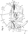
- the elastic recall element 51 comprises a second end connected to a first point 61 of the coupling body 11 so that the first elastic recall element 51 passes from a more elongated position corresponding to the closing position of the opening apparatus 10 as shown in particular in Figure 4 to a less elongated position corresponding to the opening position of the opening apparatus 10 as shown in particular in figures 7 and 8 .
- connection means 48 is a means for regulating the first elastic recall element 51 and is mounted with the first point 61 of the coupling body 11.
- the more elongated position of the first elastic recall element 51 provides that the first elastic recall element 51 can recall the lever 45 by rotating the drawer 30 in the opening position of the opening apparatus 10.
- the opening apparatus 10 comprises leverage means 85 comprising a pedal 80 and at least one pulling cable 81.
- the pulling cable 81 comprises a first end 83 connected to the second portion 47 of the lever 45 and a second end 84 connected to the leverage means 85 of the pedal 80.
- the pedal 80 is adapted to pass from a raised position corresponding to the opening position of the opening apparatus 10 to a lowered position corresponding to the closing position of the opening apparatus 10, that is, operating in reverse with respect to the state of the prior art.
- the raised position of the pedal 80 provides that the first elastic recall element 51 is in the less elongated position.
- the pulling cable 81 Passing from the raised position to the lowered position of the pedal 80, the pulling cable 81 is pulled by the leverage means 85 and moves the lever 45 making it rotate about the first rotation axis passing the drawer 30 from the opening angular position to the closing angular position, by passing the opening apparatus 10 from the opening position to the closing position and by passing the first elastic recall element 51 from the less elongated position to the more elongated position.
- the first and second elastic recall elements 51 and 52 are in the most elongated position ready to open the drawer 30 and pass the opening apparatus 10 from the closing position to the opening position without using electric batteries and thus saving electricity.
- the pedal 80 can be in any position.
- the opening position of the opening apparatus 10 provides that the drawer 30 is in an opening angular position as shown in figures 7-9 , 13 where the waste bag can be inserted inside the drawer 30 through the chamber 35 of predefined volume, passing from the opening position to the closing position of the opening apparatus 10. Subsequently, the drawer 30 rotates about the first rotation axis by closing the chamber 35 directed towards the outside of the container 100 and directing the opening of the chamber 35 of predefined volume towards the inside of the containment chamber 103 as shown in figure 12 .
- the closing position of the opening apparatus 10 provides that the drawer 30 is in the closing angular position as shown in figures 3-6 , 11 , completely closing the chamber 35 of predefined volume towards the outside of the container 100 and opening it to its utmost extent towards the inside of the containment chamber 103.
- the opening apparatus 10 comprises the tilting wall 70, a spacing bar 90 and a second elastic recall element 52 adapted to pass from a more elongated position to a less elongated position.
- the tilting wall 70 comprises an upper portion 71, a median portion 73 and a lower portion 72.
- the tilting wall 70 comprises a transverse section with curvilinear shape which follows the transverse section with circular-sector shape of the drawer 30, so that during the rotation of the drawer 30 from the opening position to the closing position of the opening apparatus 10 the tilting wall 70 does not interfere with the drawer 30 and can close the chamber 35 as long as the opening apparatus 10 is in the closing position with respect to the outside.
- the upper portion 71 of the tilting wall 70 is hinged at a third point 63 of a rear portion of the coupling body 11 and defines a second rotation axis which is parallel to the first rotation axis about which the drawer 30 rotates.
- the tilting wall 70 is located under the access opening defined by the chamber 35 of predefined volume formed by the drawer 30 and by the cap 12 when the drawer 30 passes from the angular closing position to one of the multiple non-return angular positions.
- the tilting wall 70 rotates about the second rotation axis.
- the tilting wall 70 is bonded in its rotation about the second rotation axis by the spacing bar 90.
- the tilting wall 70 passes from a closing position of an access opening of the chamber 35 of predefined volume which leads to the containment chamber 103 of the container 100 which corresponds to the opening position of the opening apparatus 10 to an opening position of the access opening to the chamber 35 of predefined volume which leads to the containment chamber 103 of the container 100 which corresponds to the closing position of the opening apparatus 10.
- the spacing bar 90 comprises an upper end 91 and a lower end 92.
- a median point 75 of the median portion 73 of the tilting wall 70 is hinged at the lower end 92 of the spacing bar 90 so as to bond the rotation of the spacing bar 70 about the second rotation axis.
- a first pawl 76 mounted above the tilting wall 70 comprises the median point 75.
- the first pawl 76 is of suitable shape so that the spacing bar 90 can rotate pivoted at the median point 75 within two stop ends and therefore can only rotate within an angle defined by the shape of the first pawl 76.
- An upper end 91 of the spacing bar 90 is hinged with a fourth point 65 of the guide element 20 as shown in particular in figures 6 and 10 .
- a second pawl 66 mounted above the guide element 20 comprises the fourth point 65 of the guide element 20.
- the second pawl 66 is of a suitable shape so that the spacing bar 90 can rotate pivoted at the fourth point 65 within two stop ends and therefore can only rotate within an angle defined by the shape of the second pawl 66.
- the second elastic recall element 52 comprises an upper end connected with a second point 62 of the coupling body 11 and a lower end connected with an upper point 74 of the upper portion 71 of the tilting wall 70.
- the upper point 74 is spaced by a predefined space from the third point 63 where the upper portion 71 of the tilting wall 70 is hinged with the coupling body 11.
- the second elastic recall element 52 is adapted to pass from a more elongated position to a less elongated position. As shown in particular in figures 4 and 5 , the more elongated position of the second elastic recall element 52 corresponds to the closing position of the opening apparatus 10, to the angular closing position of the drawer 30 and to the multiple non-return positions of the drawer 30.
- the less elongated position of the second elastic recall element 52 corresponds to the opening position of the opening apparatus 10 and to the opening angular position of the drawer 30.
- the second elastic recall element 52 in the less elongated position is adapted to keep the tilting wall 70 in position.
- the tilting wall 70 in the closing position advantageously avoids the possibility of forcing the drawer 30 to deliver a higher waste volume than allowed both when the drawer 30 is in the angular opening position and when the drawer 30 is in one of the multiple non-return positions.
- the tilting wall 70 advantageously allows keeping the access opening to the containment chamber 103 of the container 100 closed when the opening apparatus 10 is in the opening position so that only the predetermined volume defined by the walls 31-33 of the drawer 30 and by the cap 12 of the opening apparatus 10 can be delivered.
- the pedal 80 Passing from the opening position of the opening apparatus 10 to the closing position of the opening apparatus 10, the pedal 80 is pushed with a user's foot from the raised position to the lowered position, pulling the pulling cable 81 pivoted to the upper portion 47 of the lever 45 and rotating the drawer 30 about the first rotation axis.
- the drawer 30, by rotating, pushes the guide element 20 to rotate about the point 25 and to open the tilting wall 70 making the tilting wall 70 rotate in a bonded manner and tensioning the second elastic recall means 52 which passes from the less elongated position to the more elongated position.
- the tilting wall 70 opens only when the pin 36 of the drawer 30 arrives in the recess 27 of the guide slot 26 of the guide element 20 and pushes the guide element 20 downwards, making it rotate about the fourth rotation axis about the point 25 of the coupling body 11.
- the tilting wall 70 opens snap-fittingly and the waste bag is pushed towards an internal wall of the containment chamber 103 for waste of the container 100 advantageously preventing the waste bag from falling by gravity forming a pyramid of waste bags with other waste bags.
- the opening by snap fit occurs due to the change in curvature of the guide slot 26 when the pin 36 of the drawer 30 reaches the recess 27 of the final portion 27 of the guide slot 26.
- the elastic recall element 52 has the function of cushioning vibrations.
- the waste bag is catapulted by means of the kinetic energy accumulated during the rotation of the drawer 30.
- the solid dihedral shape of the drawer 30 allows increasing the kinetic energy of the waste bag since there is an angle between the front wall 31 and the rear wall 32 of the drawer 30. If the tilting wall 70 were not there, the waste bag would first fall into the chamber 103 without acquiring sufficient kinetic energy to be pushed towards the walls of the containment chamber 103.
- the thrust given to the waste bag by the tilting wall 70 advantageously allows preventing the opening apparatus 10 from being jammed, that no pyramid of waste is formed under the drop point of the waste bag, that the containment chamber 103 for waste of the container 100 is filled homogeneously and as effectively as possible.
- the lack of the tilting wall 70 would cause the waste bag to fall by gravity immediately under the predefined chamber 35 for housing waste forming a pyramid of waste bags.
- the drawer 30, passing from the closing position of the opening apparatus 10 to the opening position of the opening apparatus 10 passes from the angular closing position to the opening angular position.
- the pin 36 slides inside the guide slot 26.
- the pin 36 stops before reaching the upper stop and pushes the guide element 20 upwards, making it rotate about the point 25 of the fourth rotation axis.
- the curvilinear guide slot 26 has the function of keeping the tilting wall 70 adjacent to the drawer 30 in position and the curvature has an extension of the angle greater than the rotation of the drawer 30.
- the centre of the curvature of the guide slot 26 lies in the first rotation axis of the drawer 30.
- the guide element 20 stops its rotation motion when an upper portion 22 of the guide element 20 abuts against a stop element 122 of the cap 12 of the coupling body 11.
- the stop 122 removes a degree of freedom when the tilting wall 70 is in the closing position otherwise the friction on the guide element 20 could cause the tilting wall 70 to rub on the drawer 30, which the curvilinear shape of the guide slot 26 advantageously avoids, advantageously preserving the elements of the opening apparatus 10 for a longer time.
- the second elastic recall element 52 avoids vibrations and favours the sliding of the drawer 30 and of the pin 36 inside the guide slot 26.
- the action of the guide slot 26, of the second elastic recall element 52 and of the weight of the tilting wall 70 allows moving the tilting wall 70 without providing electric motors that would consume electric batteries.
- first point 61 is provided to be positioned in a front portion of the coupling body 11, while the second point 62 is provided to be positioned in a rear portion of the coupling body 11 so that the first elastic recall element 51 and the second elastic recall element 52 are in a less elongated position when the opening apparatus 10 is in the opening position as shown in particular in figure 8 and vice versa the first elastic recall element 51 and the second elastic recall element 52 are in a more elongated position when the opening apparatus 10 is in the closing position as shown in particular in figure 4 .
- the opening apparatus 10 of the container 100 comprises a control unit (not shown in the figures) and a lock 200, preferably a latch lock, which passes from an opening position to a closing position adapted to keep the opening apparatus 10 in the closing position.
- a control unit not shown in the figures
- a lock 200 preferably a latch lock, which passes from an opening position to a closing position adapted to keep the opening apparatus 10 in the closing position.
- the lock 200 of the opening apparatus 10 is mounted on one side, the right one, of the opening apparatus 10, as shown in figures 11-15 .
- the lock 200 comprises a toothed flange 201 which comprises a first portion 210 rotatably mounted with the right hub 40 and pivoted with the hub 40 so as to rotate about the first rotation axis in a single piece with the drawer 30.
- the toothed flange 201 comprises a second portion 220 comprising a first tooth 221 and a second tooth 222.
- the toothed flange 201 comprises a multiplicity of magnets or other indicators adapted to signal its position relative to at least one position sensor which checks the rotation of the toothed flange 201.
- the lock 200 comprises a bracket 202 adapted to engage with the teeth 221, 222 of the toothed flange 201 and adapted to pass from an engaged position with the first tooth 221 which corresponds to the closing position of the opening apparatus 10 and to the angular closing position of the drawer 30, to a multiplicity of non-return angular positions where the bracket 202 is engaged in a space between the first 221 and the second tooth 222 of the toothed flange 201 which corresponds to the multiplicity of non-return angular positions of the drawer 30 during the passage between the closing position and the opening position of the opening apparatus 10.
- the bracket 202 remains disengaged from the toothed flange 201 when the bracket 202 passes into a disengagement position, leaving the toothed flange 201 free to rotate.
- the bracket 202 comprises a third elastic recall element 224 adapted to pass from a relaxed position to a tension position.
- the disengagement position of the bracket 224 provides that the third elastic recall element 224 is in the tension position, ready to recall the bracket 202 in the engagement positions with the teeth 221, 222 or with the space between the teeth 221, 222 of the toothed flange 201.
- the elastic recall elements 51 and 52 respectively move the rotation of the drawer 30, the rotation of the guide element 20 and the bonded rotation of the tilting wall 70 of the opening apparatus 10 by passing the opening apparatus 10 from the closing position to the opening position without using batteries and thus advantageously saving the charge of the electric battery.
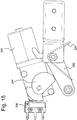
- the lock 200 comprises a DC motor 205 powered by the electric battery of the opening apparatus 10, a cam 204 pivoted with the motor 205 and rotated according to a third rotation axis by the motor 205.
- the lock 200 comprises a switch 206 through which the motor 205 is powered.
- the cam 204 is rotated by the motor 205 and passes from a multiplicity of positions which do not press the switch 206 to a pressure position against the switch 206 adapted to press the switch 206 and switch off the motor 205.
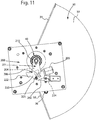
- the bracket 202 is in the engagement position with the first tooth 221 of the toothed flange 201 keeping the lock 200 in a locked position which does not allow the drawer 30 to pass from the angular closing position to the angular opening position and therefore not to pass the opening apparatus 10 from the closing position to the opening position.
- the motor 205 rotates the cam 204.
- the cam 204 pushes the bracket 202 in such a way as to pass the bracket 202 from the engagement position with the first tooth 221 to the multiplicity of engagement positions between the first tooth 221 and the second tooth 222 of the toothed flange 201 as shown in figure 12 .
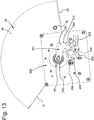
- the motor 205 continues to rotate the cam 204 until the bracket 202 passes to the disengaged position from the toothed flange 201 as shown in figures 13 and 14 .
- the toothed flange 201 is free to rotate and causes the drawer 30 to rotate in the angular opening position and the opening apparatus 10 in the opening position.
- the cam 204 pushes the switch 206 causing the motor 205 to switch off.
- the third elastic element 224 is in the tension position.
- the pedal 80 is lowered by pulling the pulling cable 81 and passing the opening apparatus 10 from the opening position to the closing position.
- the closing position of the opening apparatus 10 corresponds to the engagement position of the bracket with the first tooth 221 of the toothed flange 201.
- the control unit is mounted inside a metal box 300 of the opening apparatus 10.
- the control unit comprises at least one memory and a processor adapted to control at least the motor 205.
- the metal box 300 mounts five antennas electrically connected to the control unit which is in communication with a control unit or with vehicles or with other control units of other containers.
- the control unit advantageously allows preventing the five antennas from interfering with each other and with other radio communication systems.
- the five antennas can allow LTE, 3G, 4G, LoRaWAN, WI-FI, radio, RFID tag readers, GPS communication.
- the control unit is adapted to read the position of the drawer 30 by means of the magnetic elements of the toothed flange 201 or other angular position sensors.
- the opening apparatus 10 also comprises a position detector, for example a GPS, for communicating the position of the container 100.
- a position detector for example a GPS
- control unit It is possible to communicate with the control unit to transmit information or receive information to and from the container 100 by programming the control unit remotely or closely. For example, from the remote operating centre it is possible to control all the control units of the opening apparatuses 10 by commanding to remain in the opening position or to remain in the closing position.
- the lever 45, the first elastic recall element 51, the lock 200 and the leverage system 85 with pedal 80 cooperate synergistically with the tilting wall 70 with the spacing bar 90 and the guide element 20 of the opening apparatus 10 so as to make the push movement of the waste bag more effective and efficient by avoiding the creation of a pyramid of waste and that the opening apparatus 10 works without jamming, which is solid, safe and that allows predetermining a defined volume of waste to be thrown through it, preventing deliveries of volumes of waste higher than allowed, which allows passing from the closing position to an opening position without any contact with parts of the human body and only if there is an identification of a user enabled to throw waste bags, which is energy efficient, who consumes little electric battery.
- the opening apparatus 10 allows achieving the requirements and objectives required by the current Emilia Romagna Regional Law relating to the Punctual Fee, the so-called TCP.
- the TCP aims at monitoring the number of deliveries of each user, in this case limited to a maximum of 30 litres of volume for each delivery, in order to be able to apply a tax proportional to the actual annual uses of the deliverer.
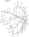
- an alternative guide element 20 comprises a second slot 28 on the upper portion 22 of the guide element 20.
- the drawer 30 comprises a further pin 37 adapted to engage inside the second slot 28 of the guide element 20.
- the further pin 37 enters the second slot 28 by pushing the guide element 20 to rotate about the fourth rotation axis identified by point 25 causing the tilting wall 70 to open even more by snap fitting.
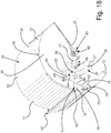
- the tilting wall 70 integrally mounts a push element 77.
- the push element 77 is a wall which protrudes the upper portion 71 of the tilting wall towards the chamber 35. As shown in figures 18 and 19 in the opening position of the opening apparatus 10 the push element 77 does not interfere with the waste bag and follows the curvilinear shape of the tilting wall 70.
- the push element 77 follows the transverse section with circular-sector shape of the drawer 30, so that during the rotation of the drawer 30 from the opening position to the closing position of the opening apparatus 10 the push element does not interfere with the drawer 30.
- the push element 77 which protrudes towards the front wall 31 like a hook advantageously allows pushing towards the rear wall 32 a possible wet or humid waste bag that has adhered to the front wall 31 allowing to increase the kinetic energy of the waste bag pushed towards the containment chamber 103.
- the same effect of increasing the thrust energy by the push element 77 occurs with the side walls 33, as well as with the front wall 31.
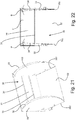
- the drawer 30 also comprises two internal draft walls 38 arranged coupling with the side walls 33.
- the volume of the chamber 35 of the drawer 30 for containing the waste bag is restricted by the two internal draft walls 38.
- Each internal draft wall 38 has a shape that follows that of the respective side wall 33.
- a rear portion 382 of each of the internal draft walls 38 mates with a rear side of the side wall 33 and with sides of the rear wall 32.
- the internal draft wall 38 gradually moves away from the corresponding side wall 33.
- the internal draft wall 38 at rest forms a draft angle ⁇ with the respective side wall 33 which is comprised between 2 and 15 sexagesimal degrees, where the draft angle ⁇ is measured in projection on a geometric plane which passes through the ends of the two radial walls 31 and 32 as shown in figure 22 .
- the internal draft walls 38 are elastic in that they are connected to the drawer 30 only on the side mating between the rear wall 32 and the rear portion 382 of the internal draft wall 38, that is, each internal draft wall 38 can oscillate about the draft angle ⁇ passing from a position of maximum approach with the respective side wall 33 to a position of maximum distance from the respective side wall 33.
- the internal draft walls 38 allow reducing an engagement angle between the waste bag and chamber 35 with respect to the direction of discharge of the waste inside the chamber 103, reducing the friction between the bag and the walls of the chamber 35 and even more avoiding that a wet or humid waste bag can adhere to the walls of chamber 35.
- the internal draft walls 38 reduce the inlet opening of the waste bag from the front wall part 31 with respect to the outlet opening of the waste bag from the rear wall part 32.
- the internal draft walls 38 are also fixed to the front wall 31 so that the internal draft walls 38 are rigidly connected to both the front wall 31 and the rear wall 32.
- the internal draft walls 38 do not oscillate about the draft angle ⁇ .
- This alternative is advantageous in that it is provided that the curvilinear flaps of the side walls 33 close with the curvilinear side flaps of the internal draft walls 38 so as to completely close every possible interspace between the walls 33 and 38 so that no interspaces accessible from the outside are formed or where dirt accumulates.
- an internal face of the front wall 31 of the drawer 30 comprises at least two first strips 39 parallel to each other which rise from the surface of the internal face of the front wall 31.
- the presence of the first strips 39 allows increasing the friction between a waste bag, even wet or humid, which would otherwise get stuck between an edge of the cap 12 and the edge of the front wall 31 of the drawer 30, due to the centrifugal force following the rotation of the drawer 30 in the passage from the opening position to the closing position.
- the present of the first strips 39 advantageously allows during the introduction of the waste bag by the user not to slide the bag out of the chamber 35 of the drawer 30 since the first strips 39 are arranged horizontally, i.e. parallel to the rotation axis of the drawer 30.
- the rear wall 32 is provided to comprise a multiplicity of second strips 34.
- the second strips 34 are arranged parallel to each other and rise from the surface of an internal face of the rear wall 32.
- the second strips 32 are arranged vertically, i.e. perpendicular to the rotation axis of the drawer 30, so that when the opening apparatus 10 is in the closing position and the drawer 30 is rotated towards the inside of the containment chamber 103, the second strips 34 reduce the adhesion of a waste bag to the rear wall 32 by not decreasing the kinetic thrust.
- the presence of the second strips 34 advantageously allows not to reduce the thrust of kinetic energy even of a bag of wet or humid waste.
- the second strips 34 also have a trapezoidal shape, that is, they comprise a first portion 341 close to the internal face of the front wall 31 and a second portion 342 on the opposite side towards the containment chamber 103, wherein the first portion 341 is more raised from the internal face of the rear wall 32 with respect to the second portion 342, so as to facilitate the sliding of the waste bag by increasing an emptying angle.
- first portion 341 and the second portion 342 are raised with the same height measure with respect to the internal face of the rear wall 32.
- the second strips 34 can be U-shaped folded sheets which rise from the internal face of the rear wall 32.
- the latter alternative allows decreasing the adhesion surface of the bag to the rear wall 32 of the drawer 30.
Landscapes
- Engineering & Computer Science (AREA)
- Mechanical Engineering (AREA)
- Refuse Receptacles (AREA)
Abstract
Description
- The present invention relates to an opening apparatus for a waste container.
- In the state of the art, containers for waste bags are known comprising opening apparatuses which pass from a closing position to an opening position by means of a pedal connected to leverage systems. Pressing the pedal, the opening apparatus passes from the closing position to the opening position in which a user can throw a waste bag inside a chamber of the container through an opening of the opening apparatus. There are containers comprising opening apparatuses mounted with containers and comprising a prehensile lever to be raised by hand to open an inlet opening towards the chamber of the container.
- There are electronic recognition apparatuses adapted to control a lock of the opening apparatus to prevent the opening apparatus from passing from a closing position to an opening position preventing the insertion of waste bags.
- Disadvantageously, it is necessary to touch the container with one hand or foot in order to pass the opening apparatus from a closing position to an opening position.
- Disadvantageously, the opening apparatus during a passage between a closing position to an opening position leaves an opening in the chamber of the container open, allowing the wrong insertion of waste bags.
- Disadvantageously, the insertion of waste bags through the opening of the opening apparatus causes the bags to fall one on top of the other creating a pyramid of bags. The pyramid-arranged bags do not homogeneously fill the chamber of the container, preventing the use of all the space available in the chamber. The pyramid of bags can come into conflict with opening and closing mechanisms of the opening apparatus, leaving the container jammed in an intermediate position, or jammed in the opening or closing position.
- Disadvantageously, the opening and closing mechanisms of the container are energy-inefficient and consume electric batteries in a short time.
- The object of the present invention is to provide an opening apparatus separably mountable with a waste container which overcomes the disadvantages set forth above and which functions without jamming, which is solid, safe and which allows predetermining a defined volume of waste to be thrown through it preventing the delivery of higher volumes of waste than allowed, which in the closing position has no access openings, nor even partial, which allows passing from a closing position to an opening position without any contact with parts of the human body and only if there is an identification of a user authorized to throw waste bags, which is energy efficient, which consumes little electric battery, which cooperates with the elements of the opening apparatus according to claim 1.
- In accordance with the invention, this object is achieved with an opening apparatus separably mountable with a waste container according to claim 1.
- Other features are envisaged in the dependent claims.
- The features and advantages of the present invention will be more apparent from the following description, which is to be understood as exemplifying and not limiting, with reference to the appended schematic drawings, wherein:
-
figure 1 is a front view of a container comprising an opening apparatus according to the present invention; -
figure 2 is a side view of the container offigure 1 ; -
figure 3 is an axonometric view of the opening apparatus separated from the container and in the closing position; -
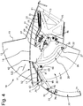
figure 4 is a side view from the left of the opening apparatus in the closing position; -
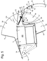
figure 5 is a side view from the right of the opening apparatus in the closing position; -
figure 6 shows an uncovered side view from the left of the opening apparatus in the closing position; -
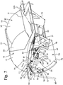
figure 7 is a perspective view of the opening apparatus separated from the container and in the opening position; -
figure 8 is a side view from the left of the opening apparatus in the opening position; -
figure 9 is a side view from the right of the opening apparatus in the opening position; -
figure 10 shows an uncovered side view from the left of the opening apparatus in the opening position; -
figure 11 shows an uncovered side view from the right of a detail of the opening apparatus in the closing position comprising a lock in the closing position; -
figure 12 shows an uncovered side view from the right of the detail of the opening apparatus in one of the multiple non-return positions and of the lock in the non-return position; -
figure 13 shows an uncovered side view from the right of the detail of the opening apparatus in the opening position and of the lock in the opening position; -
figure 14 shows an axonometric view offigure 13 ; -
figure 15 shows a detail of the lock in the opening position comprising a cam in contact with an ignition switch of a motor; -
figure 16 shows an alternative opening apparatus comprising an alternative guide element in a non-return position; -
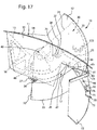
figure 17 shows the alternative opening apparatus offigure 16 in a closing position; -
figure 18 shows a partially uncovered axonometric view of an alternative opening apparatus in the opening position comprising a push element integral with the tilting wall; -
figure 19 shows a side view of the alternative opening apparatus offigure 18 in the opening position; -
figure 20 shows a section view of the alternative opening apparatus offigure 18 in the closing position; -
figure 21 shows a partially uncovered axonometric view of an alternative drawer of the opening apparatus comprising two internal draft walls; -
figure 22 shows a projection view of the alternative drawer offigure 21 on a geometric plane which passes from the extreme sides of a chamber of the drawer; -
figure 23 shows a projection view of an alternative drawer comprising a multiplicity of strips which protrude upwards with respect to a rear wall of the drawer; -
figure 24 shows a section view of the alternative drawer offigure 23 . - With reference to the aforementioned figures and in particular
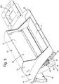
figures 1 and 2 , acontainer 100 for waste divided into predefined volumes where each predefined volume of waste is a bag for waste is shown. - The
container 100 comprises a box-like body 101, alid 102 and acontainment chamber 103 for waste. Thelid 102 of the box-like body 101 comprises at least twoopenable side flaps lid 102 provides at least one access opening to thecontainment chamber 103 for waste by opening the twoside flaps lid 102 passes to the opening configuration when thecontainer 100 is opened, inclined or overturned to be emptied of the waste contained in thecontainment chamber 103 by means of enabled waste collection means, such as for example waste collection vehicles not shown in the figures. - Alternatively, the
lid 102 can also comprise only anopenable flap - The
container 100 comprises anopening apparatus 10 which is separably mountable with thecontainer 100 and is adapted to pass from a closing position which does not provides any access openings to thecontainment chamber 103 to an opening position which provides at least an access opening to thecontainment chamber 103. In particular, it is provided that theopening apparatus 10 is separably mountable with at least one of the twoside flaps lid 102 of the box-like body 101 of thecontainer 100. - To facilitate the insertion operations of predefined volumes of waste by people, the
opening apparatus 10 is separably mounted with aside flap 111 of thelid 102 so that when theopening apparatus 10 is in the opening position it occurs that the access opening to thecontainment chamber 103 is directed towards one side of thecontainer 100. Advantageously, this ergonomic position of theopening apparatus 10 also facilitates people of short stature to insert the waste bag comfortably and effortlessly in the opening of theopening apparatus 10. - As shown in particular in
figures 3-10 , theopening apparatus 10 comprises acoupling body 11 couplable with theside flap 111 of thelid 102 of thecontainer 100. Thecoupling body 11 comprises acouplable portion 14 with theside flap 111 of thelid 102 whose shape is comparable with that of theside flap 111 and complementary with theside flap 111 so that it can be easily mountable with it 111. - Advantageously, the shape of the
coupling portion 14 is complementary to the shape of theside flap 111 or complementary to another portion of thelid 102 where it is preferable to mount theopening apparatus 10 so that theopening apparatus 10 can be mounted with any type ofcontainer 100. - The
coupling body 11 comprises anupper cap 12 which protrudes upwards from thecouplable portion 14 of thecoupling body 11 and a lowerlimiting wall 13. - The
cap 12 and thelower limitation wall 13 define anopening 15 of theopening apparatus 10 which leads to thechamber 103 of thecontainer 100. - The
cap 12 protrudes above the opening 15 and is adapted to protect the opening 15 from rain so as not to allow water to drip into thecontainment chamber 103. - The
coupling body 11 further comprises alower portion 16 which protrudes downwards starting from thecoupling portion 14. - Advantageously, the elements of the
coupling body 11 are made of metal sheet suitable for stiffening the structure of theopening apparatus 10, allowing it to withstand the stresses to which thecontainer 100 is subjected during operations for delivering waste bags and for emptying thecontainer 100 and to allow theopening apparatus 10 to be mounted with any type ofcontainer 100. - The
opening apparatus 10 comprises adrawer 30 rotatably mounted with thecoupling body 11 defining a first rotation axis of thedrawer 30. - The
drawer 30 is mounted at the opening 15 between thecap 12 and thelower wall 13 of thecoupling body 11. - The first rotation axis of the
drawer 30 passes through thelower portion 16 of thecoupling body 11. - The
drawer 30 is rotatably mounted with thelower portion 16 of thecoupling body 11 by means of twohubs 40, one on the left and one on the right of theopening apparatus 10. Each of the twohubs 40 comprises bearings or ball or rolling elements of the sealed and self-lubricating type so as to advantageously avoid getting dirty and avoid the entry of dust, or dirt or water. - The
drawer 30 has a solid dihedral geometrical shape and comprises a transverse section with circular-sector shape which comprises tworadial walls front wall 31 and arear wall 32, protruding along two different radial directions with respect to the first rotation axis of thedrawer 30 defining an angle θ of 135 sexagesimal degrees measured on a geometric plane perpendicular to the first rotation axis, as shown infigures 6 and10 . - The
drawer 30 also comprises twoside walls 33 adapted to form together with the tworadial walls 31 and 32 a chamber of thedrawer 30 for containing the waste bag. - The walls 31-33 of the
drawer 30 together with an internal surface of thecap 12 define achamber 35 of predefined volume for housing a waste bag when theopening apparatus 10 is in the opening position as shown in particular infigures 7-9 . In particular, it is provided that the predefined volume of thechamber 35 as defined above is adapted to contain a 30-litre waste bag. - Alternatively, it is possible to provide that if a volume of waste bag other than 30 litres is to be housed, then the angle θ between the
front wall 31 and therear wall 35 should vary accordingly so that the walls 31-33 of thedrawer 30 together with the internal surface of thecap 12 define achamber 35 with another predefined volume for housing a waste bag of different volume. - Alternatively, it is possible to provide that if a volume of waste bag other than 30 litres is to be housed, then the geometry of the
cap 12 could be modified without changing the angle θ between thefront wall 31 and therear wall 35. - The
drawer 30 comprises twopins 36 which protrude outwardly from both theside walls 33 of thedrawer 30 along a direction parallel to the direction of the first rotation axis. - The
opening apparatus 10 comprises aguide element 20 which is pivoted at apoint 25 of thelower portion 16 of thecoupling body 11. Theguide element 20 rotates about thepoint 25 defining a fourth rotation axis. - The
guide element 20 comprises aguide slot 26 of curvilinear shape. A lower end of theguide slot 26 comprises arecess 27. Therecess 27 of theguide slot 26 is preferably a portion of theguide slot 26 with a curvilinear shape with an inverse curvature with respect to that of the remaining portion of theguide slot 26. - The first rotation axis of the
drawer 30 and the fourth rotation axis of theguide element 20 are parallel. - Each of the two
pins 36 of thedrawer 30 slides inside theguide slot 26 of theguide element 20 of theopening apparatus 10. In fact, aguide element 20 is provided both on the left and on the right of theopening apparatus 10. - The
guide slot 26 of theguide element 20 has a curvature such as to allow thedrawer 30 to rotate safely about the first rotation axis within maximum two stops, an upper stop which corresponds to an upper end of theguide slot 26 and therecess 27 of the lower end of theguide slot 26 of theguide element 20. - The curvilinear shape of the
guide slot 26 has variable radii of curvature according to angular positions of thedrawer 30 so as to open a tiltingwall 70 in the closing position of theopening apparatus 10. - The
drawer 30 remains in its seat in an advantageously safe manner rotating about the first rotation axis by means of the twohubs 40 and being guided by the twopins 36 which slide within theguide slot 26. - The
recess 27 of the lower end of theguide slot 26 is reached by thepin 36 of thedrawer 30 when theopening apparatus 10 is in a non-return position. Thedrawer 30 drags theguide element 20 downwards through thepin 36 causing the tiltingwall 70 to open until theopening apparatus 10 is in the closing position and the tiltingwall 70 is in the opening position. - The shape of the
recess 27 of theguide slot 26 of theguide element 20 is specially made so that the tiltingwall 70 can be opened by snap fitting as much as possible in order to better launch the waste bag towards the wall of thecontainment chamber 103. - The
pin 36 of thedrawer 30 and therecess 27 coupled between them advantageously allow to strengthen the closing position of theopening apparatus 10 avoiding it from being opened accidentally or that theopening apparatus 10 can be forced. - The
hub 40 comprises a damping device which is mounted under thebracket 41 in the figures and which allows dampening the opening movement of thedrawer 30 during the passage from the closing position to the opening position of theopening apparatus 10. - Alternatively, it is possible to provide that the damping device can also be used for the passage from the opening position to the closing position of the
opening apparatus 10. - The
drawer 30 is adapted to pass from a closing angular position shown infigure 11 which corresponds to the closing position of theopening apparatus 10 to a multiplicity of non-return angular positions one of which positions is shown infigure 12 , each of the non-return positions of thedrawer 30 corresponds to respective positions that theopening apparatus 10 takes on during a passage step from the opening position to the closing position, up to an angular opening position of thedrawer 30 shown infigures 13 and14 which corresponds to the opening position of theopening apparatus 10. - The
hub 40 comprises alever 45. Thelever 45 is mounted in a single piece with thehub 40 and rotates as a single piece with thehub 40 about the first rotation axis. - The
lever 45 comprises afirst portion 46 and asecond portion 47 which extend along two different radial directions with respect to the first rotation axis. The two radial directions are substantially opposite to each other. Substantially opposed because an angle between the two radial directions is provided which is adapted to deamplify the ratio of the force lever of theelastic recall element 51. - The
first portion 46 of thelever 45 is a first arm of thelever 45 and is mounted in a single piece with therear wall 32 of thedrawer 30 so that when the lever rotates about the first rotation axis, thedrawer 30 also rotates about the first rotation axis. - The
second portion 47 of thelever 45 is a second arm of thelever 45 and is connected by means of a connection means 48 to a first end of a firstelastic recall element 51 of theopening apparatus 10. The firstelastic recall element 51 preferably consists of two springs. - The
elastic recall element 51 comprises a second end connected to afirst point 61 of thecoupling body 11 so that the firstelastic recall element 51 passes from a more elongated position corresponding to the closing position of theopening apparatus 10 as shown in particular inFigure 4 to a less elongated position corresponding to the opening position of theopening apparatus 10 as shown in particular infigures 7 and8 . - Alternatively, it is provided that the connection means 48 is a means for regulating the first
elastic recall element 51 and is mounted with thefirst point 61 of thecoupling body 11. - The more elongated position of the first
elastic recall element 51 provides that the firstelastic recall element 51 can recall thelever 45 by rotating thedrawer 30 in the opening position of theopening apparatus 10. - As shown in particular in
figures 1, 2 ,7 and8 , theopening apparatus 10 comprises leverage means 85 comprising apedal 80 and at least one pullingcable 81. The pullingcable 81 comprises afirst end 83 connected to thesecond portion 47 of thelever 45 and asecond end 84 connected to the leverage means 85 of thepedal 80. - Starting from the opening position of the
opening apparatus 10, thepedal 80 is adapted to pass from a raised position corresponding to the opening position of theopening apparatus 10 to a lowered position corresponding to the closing position of theopening apparatus 10, that is, operating in reverse with respect to the state of the prior art. - The raised position of the
pedal 80 provides that the firstelastic recall element 51 is in the less elongated position. - Passing from the raised position to the lowered position of the pedal 80, the pulling
cable 81 is pulled by the leverage means 85 and moves thelever 45 making it rotate about the first rotation axis passing thedrawer 30 from the opening angular position to the closing angular position, by passing theopening apparatus 10 from the opening position to the closing position and by passing the firstelastic recall element 51 from the less elongated position to the more elongated position. In this way, in the closing position of theopening apparatus 10, the first and secondelastic recall elements drawer 30 and pass theopening apparatus 10 from the closing position to the opening position without using electric batteries and thus saving electricity. - When the
opening apparatus 10 is instead in the closing position, the pedal 80 can be in any position. - The opening position of the
opening apparatus 10 provides that thedrawer 30 is in an opening angular position as shown infigures 7-9 ,13 where the waste bag can be inserted inside thedrawer 30 through thechamber 35 of predefined volume, passing from the opening position to the closing position of theopening apparatus 10. Subsequently, thedrawer 30 rotates about the first rotation axis by closing thechamber 35 directed towards the outside of thecontainer 100 and directing the opening of thechamber 35 of predefined volume towards the inside of thecontainment chamber 103 as shown infigure 12 . The closing position of theopening apparatus 10 provides that thedrawer 30 is in the closing angular position as shown infigures 3-6 ,11 , completely closing thechamber 35 of predefined volume towards the outside of thecontainer 100 and opening it to its utmost extent towards the inside of thecontainment chamber 103. - The
opening apparatus 10 comprises the tiltingwall 70, aspacing bar 90 and a secondelastic recall element 52 adapted to pass from a more elongated position to a less elongated position. - The tilting
wall 70 comprises anupper portion 71, amedian portion 73 and alower portion 72. - The tilting
wall 70 comprises a transverse section with curvilinear shape which follows the transverse section with circular-sector shape of thedrawer 30, so that during the rotation of thedrawer 30 from the opening position to the closing position of theopening apparatus 10 the tiltingwall 70 does not interfere with thedrawer 30 and can close thechamber 35 as long as theopening apparatus 10 is in the closing position with respect to the outside. - The
upper portion 71 of the tiltingwall 70 is hinged at athird point 63 of a rear portion of thecoupling body 11 and defines a second rotation axis which is parallel to the first rotation axis about which thedrawer 30 rotates. - The tilting
wall 70 is located under the access opening defined by thechamber 35 of predefined volume formed by thedrawer 30 and by thecap 12 when thedrawer 30 passes from the angular closing position to one of the multiple non-return angular positions. - The tilting
wall 70 rotates about the second rotation axis. The tiltingwall 70 is bonded in its rotation about the second rotation axis by the spacingbar 90. - The tilting
wall 70 passes from a closing position of an access opening of thechamber 35 of predefined volume which leads to thecontainment chamber 103 of thecontainer 100 which corresponds to the opening position of theopening apparatus 10 to an opening position of the access opening to thechamber 35 of predefined volume which leads to thecontainment chamber 103 of thecontainer 100 which corresponds to the closing position of theopening apparatus 10. - The spacing
bar 90 comprises anupper end 91 and alower end 92. - A
median point 75 of themedian portion 73 of the tiltingwall 70 is hinged at thelower end 92 of thespacing bar 90 so as to bond the rotation of thespacing bar 70 about the second rotation axis. - A
first pawl 76 mounted above the tiltingwall 70 comprises themedian point 75. Thefirst pawl 76 is of suitable shape so that thespacing bar 90 can rotate pivoted at themedian point 75 within two stop ends and therefore can only rotate within an angle defined by the shape of thefirst pawl 76. - An
upper end 91 of thespacing bar 90 is hinged with afourth point 65 of theguide element 20 as shown in particular infigures 6 and10 . - A
second pawl 66 mounted above theguide element 20 comprises thefourth point 65 of theguide element 20. Thesecond pawl 66 is of a suitable shape so that thespacing bar 90 can rotate pivoted at thefourth point 65 within two stop ends and therefore can only rotate within an angle defined by the shape of thesecond pawl 66. - The second
elastic recall element 52 comprises an upper end connected with asecond point 62 of thecoupling body 11 and a lower end connected with anupper point 74 of theupper portion 71 of the tiltingwall 70. Theupper point 74 is spaced by a predefined space from thethird point 63 where theupper portion 71 of the tiltingwall 70 is hinged with thecoupling body 11. - The second
elastic recall element 52 is adapted to pass from a more elongated position to a less elongated position. As shown in particular infigures 4 and5 , the more elongated position of the secondelastic recall element 52 corresponds to the closing position of theopening apparatus 10, to the angular closing position of thedrawer 30 and to the multiple non-return positions of thedrawer 30. - As shown in particular in
figures 8 and9 , the less elongated position of the secondelastic recall element 52 corresponds to the opening position of theopening apparatus 10 and to the opening angular position of thedrawer 30. The secondelastic recall element 52 in the less elongated position is adapted to keep the tiltingwall 70 in position. - The tilting
wall 70 in the closing position advantageously avoids the possibility of forcing thedrawer 30 to deliver a higher waste volume than allowed both when thedrawer 30 is in the angular opening position and when thedrawer 30 is in one of the multiple non-return positions. - The tilting
wall 70 advantageously allows keeping the access opening to thecontainment chamber 103 of thecontainer 100 closed when theopening apparatus 10 is in the opening position so that only the predetermined volume defined by the walls 31-33 of thedrawer 30 and by thecap 12 of theopening apparatus 10 can be delivered. - Passing from the opening position of the
opening apparatus 10 to the closing position of theopening apparatus 10, thepedal 80 is pushed with a user's foot from the raised position to the lowered position, pulling the pullingcable 81 pivoted to theupper portion 47 of thelever 45 and rotating thedrawer 30 about the first rotation axis. Thedrawer 30, by rotating, pushes theguide element 20 to rotate about thepoint 25 and to open the tiltingwall 70 making the tiltingwall 70 rotate in a bonded manner and tensioning the second elastic recall means 52 which passes from the less elongated position to the more elongated position. - The tilting
wall 70 opens only when thepin 36 of thedrawer 30 arrives in therecess 27 of theguide slot 26 of theguide element 20 and pushes theguide element 20 downwards, making it rotate about the fourth rotation axis about thepoint 25 of thecoupling body 11. Theguide element 20, by moving, moves thespacing bar 90 which makes the tiltingwall 70 move in turn by rotating it about thethird point 63 of thecoupling body 11 and passing the tiltingwall 70 from the closing position to the opening position which corresponds to the closing position of theopening apparatus 10 and which corresponds to the angular closing position of thedrawer 30. - During this bonded rotary movement of the tilting
wall 70, the waste bag which has been inserted in thepredefined chamber 35 to house the waste bag, is stopped by the tiltingwall 70 which does not drop the waste bag from thechamber 35 of thedrawer 30. When theopening apparatus 10 passes to the closing position and thedrawer 30 passes to the angular closing position, the tiltingwall 70 opens snap-fittingly and the waste bag is pushed towards an internal wall of thecontainment chamber 103 for waste of thecontainer 100 advantageously preventing the waste bag from falling by gravity forming a pyramid of waste bags with other waste bags. The opening by snap fit occurs due to the change in curvature of theguide slot 26 when thepin 36 of thedrawer 30 reaches therecess 27 of thefinal portion 27 of theguide slot 26. Theelastic recall element 52 has the function of cushioning vibrations. The waste bag is catapulted by means of the kinetic energy accumulated during the rotation of thedrawer 30. Advantageously the solid dihedral shape of thedrawer 30 allows increasing the kinetic energy of the waste bag since there is an angle between thefront wall 31 and therear wall 32 of thedrawer 30. If the tiltingwall 70 were not there, the waste bag would first fall into thechamber 103 without acquiring sufficient kinetic energy to be pushed towards the walls of thecontainment chamber 103. The thrust given to the waste bag by the tiltingwall 70 advantageously allows preventing theopening apparatus 10 from being jammed, that no pyramid of waste is formed under the drop point of the waste bag, that thecontainment chamber 103 for waste of thecontainer 100 is filled homogeneously and as effectively as possible. The lack of the tiltingwall 70 would cause the waste bag to fall by gravity immediately under thepredefined chamber 35 for housing waste forming a pyramid of waste bags. - The
drawer 30, passing from the closing position of theopening apparatus 10 to the opening position of theopening apparatus 10 passes from the angular closing position to the opening angular position. By rotating thedrawer 30, thepin 36 slides inside theguide slot 26. Thepin 36 stops before reaching the upper stop and pushes theguide element 20 upwards, making it rotate about thepoint 25 of the fourth rotation axis. In fact, thecurvilinear guide slot 26 has the function of keeping the tiltingwall 70 adjacent to thedrawer 30 in position and the curvature has an extension of the angle greater than the rotation of thedrawer 30. The centre of the curvature of theguide slot 26 lies in the first rotation axis of thedrawer 30. Theguide element 20 stops its rotation motion when anupper portion 22 of theguide element 20 abuts against astop element 122 of thecap 12 of thecoupling body 11. Thestop 122 removes a degree of freedom when the tiltingwall 70 is in the closing position otherwise the friction on theguide element 20 could cause the tiltingwall 70 to rub on thedrawer 30, which the curvilinear shape of theguide slot 26 advantageously avoids, advantageously preserving the elements of theopening apparatus 10 for a longer time. - There are spatial distances between the
third point 63 of thecoupling body 11 in which theupper portion 71 of the tiltingwall 70 is hinged and thefourth point 65 of theguide element 20 in which theupper end 91 of thespacing bar 90 is hinged and thesecond point 62 of thecoupling body 11 where the upper end of the secondelastic recall element 52 is connected so that the tiltingwall 70 can rotate about the second rotation axis and be bonded by the spacingbar 90. Advantageously, the secondelastic recall element 52 avoids vibrations and favours the sliding of thedrawer 30 and of thepin 36 inside theguide slot 26. The action of theguide slot 26, of the secondelastic recall element 52 and of the weight of the tiltingwall 70 allows moving the tiltingwall 70 without providing electric motors that would consume electric batteries. - There is a spatial distance between the
first point 61 and thesecond point 62 of thecoupling body 11. In particular, thefirst point 61 is provided to be positioned in a front portion of thecoupling body 11, while thesecond point 62 is provided to be positioned in a rear portion of thecoupling body 11 so that the firstelastic recall element 51 and the secondelastic recall element 52 are in a less elongated position when theopening apparatus 10 is in the opening position as shown in particular infigure 8 and vice versa the firstelastic recall element 51 and the secondelastic recall element 52 are in a more elongated position when theopening apparatus 10 is in the closing position as shown in particular infigure 4 . - As shown in particular in
figures 4-10 there are two spacingbars 90 on the two left and right sides of theopening apparatus 10, respectively. - As shown in particular in
figures 11-15 , theopening apparatus 10 of thecontainer 100 comprises a control unit (not shown in the figures) and alock 200, preferably a latch lock, which passes from an opening position to a closing position adapted to keep theopening apparatus 10 in the closing position. - The
lock 200 of theopening apparatus 10 is mounted on one side, the right one, of theopening apparatus 10, as shown infigures 11-15 . - As shown in particular in
figure 13 , thelock 200 comprises atoothed flange 201 which comprises afirst portion 210 rotatably mounted with theright hub 40 and pivoted with thehub 40 so as to rotate about the first rotation axis in a single piece with thedrawer 30. - The
toothed flange 201 comprises asecond portion 220 comprising afirst tooth 221 and asecond tooth 222. - The
toothed flange 201 comprises a multiplicity of magnets or other indicators adapted to signal its position relative to at least one position sensor which checks the rotation of thetoothed flange 201. - The
lock 200 comprises abracket 202 adapted to engage with theteeth toothed flange 201 and adapted to pass from an engaged position with thefirst tooth 221 which corresponds to the closing position of theopening apparatus 10 and to the angular closing position of thedrawer 30, to a multiplicity of non-return angular positions where thebracket 202 is engaged in a space between the first 221 and thesecond tooth 222 of thetoothed flange 201 which corresponds to the multiplicity of non-return angular positions of thedrawer 30 during the passage between the closing position and the opening position of theopening apparatus 10. - Finally, the
bracket 202 remains disengaged from thetoothed flange 201 when thebracket 202 passes into a disengagement position, leaving thetoothed flange 201 free to rotate. Thebracket 202 comprises a thirdelastic recall element 224 adapted to pass from a relaxed position to a tension position. - The disengagement position of the
bracket 224 provides that the thirdelastic recall element 224 is in the tension position, ready to recall thebracket 202 in the engagement positions with theteeth teeth toothed flange 201. - Once the
bracket 202 releases thetoothed flange 201 of thelock 200, theelastic recall elements drawer 30, the rotation of theguide element 20 and the bonded rotation of the tiltingwall 70 of theopening apparatus 10 by passing theopening apparatus 10 from the closing position to the opening position without using batteries and thus advantageously saving the charge of the electric battery. - The
lock 200 comprises aDC motor 205 powered by the electric battery of theopening apparatus 10, acam 204 pivoted with themotor 205 and rotated according to a third rotation axis by themotor 205. - The
lock 200 comprises aswitch 206 through which themotor 205 is powered. Thecam 204 is rotated by themotor 205 and passes from a multiplicity of positions which do not press theswitch 206 to a pressure position against theswitch 206 adapted to press theswitch 206 and switch off themotor 205. - As shown in
figure 11 , thebracket 202 is in the engagement position with thefirst tooth 221 of thetoothed flange 201 keeping thelock 200 in a locked position which does not allow thedrawer 30 to pass from the angular closing position to the angular opening position and therefore not to pass theopening apparatus 10 from the closing position to the opening position. - Once the control unit identifies a person such as the user enabled to deliver a waste bag of predefined volume, the
motor 205 rotates thecam 204. Thecam 204 pushes thebracket 202 in such a way as to pass thebracket 202 from the engagement position with thefirst tooth 221 to the multiplicity of engagement positions between thefirst tooth 221 and thesecond tooth 222 of thetoothed flange 201 as shown infigure 12 . - The
motor 205 continues to rotate thecam 204 until thebracket 202 passes to the disengaged position from thetoothed flange 201 as shown infigures 13 and14 . In the disengaged position thetoothed flange 201 is free to rotate and causes thedrawer 30 to rotate in the angular opening position and theopening apparatus 10 in the opening position. In this disengagement position of thebracket 202, thecam 204 pushes theswitch 206 causing themotor 205 to switch off. In the disengagement position of thebracket 202, the thirdelastic element 224 is in the tension position. - To reload the
lock 200 and return thebracket 202 to the engagement position first with thesecond tooth 222 and then with thefirst tooth 221 of thetoothed flange 201, thepedal 80 is lowered by pulling the pullingcable 81 and passing theopening apparatus 10 from the opening position to the closing position. - The closing position of the
opening apparatus 10 corresponds to the engagement position of the bracket with thefirst tooth 221 of thetoothed flange 201. - The control unit is mounted inside a
metal box 300 of theopening apparatus 10. The control unit comprises at least one memory and a processor adapted to control at least themotor 205. Themetal box 300 mounts five antennas electrically connected to the control unit which is in communication with a control unit or with vehicles or with other control units of other containers. The control unit advantageously allows preventing the five antennas from interfering with each other and with other radio communication systems. - In particular, the five antennas can allow LTE, 3G, 4G, LoRaWAN, WI-FI, radio, RFID tag readers, GPS communication.
- The control unit is adapted to read the position of the
drawer 30 by means of the magnetic elements of thetoothed flange 201 or other angular position sensors. - The
opening apparatus 10 also comprises a position detector, for example a GPS, for communicating the position of thecontainer 100. - It is possible to communicate with the control unit to transmit information or receive information to and from the
container 100 by programming the control unit remotely or closely. For example, from the remote operating centre it is possible to control all the control units of the openingapparatuses 10 by commanding to remain in the opening position or to remain in the closing position. - The
lever 45, the firstelastic recall element 51, thelock 200 and theleverage system 85 withpedal 80 cooperate synergistically with the tiltingwall 70 with the spacingbar 90 and theguide element 20 of theopening apparatus 10 so as to make the push movement of the waste bag more effective and efficient by avoiding the creation of a pyramid of waste and that theopening apparatus 10 works without jamming, which is solid, safe and that allows predetermining a defined volume of waste to be thrown through it, preventing deliveries of volumes of waste higher than allowed, which allows passing from the closing position to an opening position without any contact with parts of the human body and only if there is an identification of a user enabled to throw waste bags, which is energy efficient, who consumes little electric battery. - Advantageously, the
opening apparatus 10 according to the present invention allows achieving the requirements and objectives required by the current Emilia Romagna Regional Law relating to the Punctual Fee, the so-called TCP. The TCP aims at monitoring the number of deliveries of each user, in this case limited to a maximum of 30 litres of volume for each delivery, in order to be able to apply a tax proportional to the actual annual uses of the deliverer. - Alternatively, as shown in
figures 16 and17 , analternative guide element 20 comprises asecond slot 28 on theupper portion 22 of theguide element 20. Thedrawer 30 comprises afurther pin 37 adapted to engage inside thesecond slot 28 of theguide element 20. During the rotation of thedrawer 30 from the angular opening position to the multiplicity of non-return angular positions one of which is shown infigure 16 to the angular closing position shown infigure 17 , thefurther pin 37 enters thesecond slot 28 by pushing theguide element 20 to rotate about the fourth rotation axis identified bypoint 25 causing the tiltingwall 70 to open even more by snap fitting. - Alternatively, as shown in
figures 18-20 , the tiltingwall 70 integrally mounts apush element 77. Thepush element 77 is a wall which protrudes theupper portion 71 of the tilting wall towards thechamber 35. As shown infigures 18 and19 in the opening position of theopening apparatus 10 thepush element 77 does not interfere with the waste bag and follows the curvilinear shape of the tiltingwall 70. Thepush element 77 follows the transverse section with circular-sector shape of thedrawer 30, so that during the rotation of thedrawer 30 from the opening position to the closing position of theopening apparatus 10 the push element does not interfere with thedrawer 30. As shown infigure 20 in the closing position of theopening apparatus 10 and in the opening position of the tiltingwall 70, thepush element 77 which protrudes towards thefront wall 31 like a hook advantageously allows pushing towards the rear wall 32 a possible wet or humid waste bag that has adhered to thefront wall 31 allowing to increase the kinetic energy of the waste bag pushed towards thecontainment chamber 103. The same effect of increasing the thrust energy by thepush element 77 occurs with theside walls 33, as well as with thefront wall 31. - Alternatively as shown in
figures 21 and 22 thedrawer 30 also comprises twointernal draft walls 38 arranged coupling with theside walls 33. The volume of thechamber 35 of thedrawer 30 for containing the waste bag is restricted by the twointernal draft walls 38. Eachinternal draft wall 38 has a shape that follows that of therespective side wall 33. Arear portion 382 of each of theinternal draft walls 38 mates with a rear side of theside wall 33 and with sides of therear wall 32. Theinternal draft wall 38 gradually moves away from thecorresponding side wall 33. As shown infigure 22 , theinternal draft wall 38 at rest forms a draft angle ϕ with therespective side wall 33 which is comprised between 2 and 15 sexagesimal degrees, where the draft angle ϕ is measured in projection on a geometric plane which passes through the ends of the tworadial walls figure 22 . Advantageously, theinternal draft walls 38 are elastic in that they are connected to thedrawer 30 only on the side mating between therear wall 32 and therear portion 382 of theinternal draft wall 38, that is, eachinternal draft wall 38 can oscillate about the draft angle ϕ passing from a position of maximum approach with therespective side wall 33 to a position of maximum distance from therespective side wall 33. Advantageously, theinternal draft walls 38 allow reducing an engagement angle between the waste bag andchamber 35 with respect to the direction of discharge of the waste inside thechamber 103, reducing the friction between the bag and the walls of thechamber 35 and even more avoiding that a wet or humid waste bag can adhere to the walls ofchamber 35. Advantageously, theinternal draft walls 38 reduce the inlet opening of the waste bag from thefront wall part 31 with respect to the outlet opening of the waste bag from therear wall part 32. - Alternatively, the
internal draft walls 38 are also fixed to thefront wall 31 so that theinternal draft walls 38 are rigidly connected to both thefront wall 31 and therear wall 32. In this alternative, theinternal draft walls 38 do not oscillate about the draft angle ϕ. This alternative is advantageous in that it is provided that the curvilinear flaps of theside walls 33 close with the curvilinear side flaps of theinternal draft walls 38 so as to completely close every possible interspace between thewalls - Alternatively, as shown in
figures 14 ,23 and 24 , an internal face of thefront wall 31 of thedrawer 30 comprises at least twofirst strips 39 parallel to each other which rise from the surface of the internal face of thefront wall 31. Advantageously, the presence of the first strips 39 allows increasing the friction between a waste bag, even wet or humid, which would otherwise get stuck between an edge of thecap 12 and the edge of thefront wall 31 of thedrawer 30, due to the centrifugal force following the rotation of thedrawer 30 in the passage from the opening position to the closing position. The present of thefirst strips 39 advantageously allows during the introduction of the waste bag by the user not to slide the bag out of thechamber 35 of thedrawer 30 since thefirst strips 39 are arranged horizontally, i.e. parallel to the rotation axis of thedrawer 30. - Again alternatively, as shown in
figures 23 and 24 , therear wall 32 is provided to comprise a multiplicity of second strips 34. The second strips 34 are arranged parallel to each other and rise from the surface of an internal face of therear wall 32. The second strips 32 are arranged vertically, i.e. perpendicular to the rotation axis of thedrawer 30, so that when theopening apparatus 10 is in the closing position and thedrawer 30 is rotated towards the inside of thecontainment chamber 103, thesecond strips 34 reduce the adhesion of a waste bag to therear wall 32 by not decreasing the kinetic thrust. The presence of thesecond strips 34 advantageously allows not to reduce the thrust of kinetic energy even of a bag of wet or humid waste. As shown in particular infigure 24 , thesecond strips 34 also have a trapezoidal shape, that is, they comprise afirst portion 341 close to the internal face of thefront wall 31 and asecond portion 342 on the opposite side towards thecontainment chamber 103, wherein thefirst portion 341 is more raised from the internal face of therear wall 32 with respect to thesecond portion 342, so as to facilitate the sliding of the waste bag by increasing an emptying angle. - Alternatively, the
first portion 341 and thesecond portion 342 are raised with the same height measure with respect to the internal face of therear wall 32. - Alternatively, the
second strips 34 can be U-shaped folded sheets which rise from the internal face of therear wall 32. Advantageously, the latter alternative allows decreasing the adhesion surface of the bag to therear wall 32 of thedrawer 30. - The invention thus conceived is susceptible to many modifications and variants, all falling within the same inventive concept; furthermore, all details can be replaced by equivalent technical elements. In practice, the materials used, as well as the dimensions thereof, can be of any type according to the technical requirements.
Claims (16)
- Opening apparatus (10) separably mountable with a waste container (100) which comprises a containment chamber (103), said opening apparatus (10) is adapted to pass from a closing position which does not provide accessible openings to said containment chamber (103) to an opening position which provides at least an access opening to the containment chamber (103), said opening apparatus (10) comprising a coupling body (11) couplable with said container (100), said opening apparatus (10) comprising a drawer (30) rotatably mounted with said coupling body (11) defining a first rotation axis of said drawer (30), said drawer (30) and said coupling body (11) defining a chamber (35) of predefined volume for housing a waste bag of said predefined volume, the opening position of said opening apparatus (10) provides that said drawer (30) is in an opening angular position wherein said waste bag can be inserted through said chamber (35) of predefined volume, said opening apparatus (10) passing from the opening position to the closing position provides that said drawer (30) rotates about the first rotation axis closing the chamber (35) directed towards the outside of the container (100) and directing the opening of the chamber (35) of predefined volume towards the inside of the containment chamber (103), the closing position of the opening apparatus (10) provides that the drawer (30) is in the closing angular position completely closing the chamber (35) of predefined volume towards the outside of the container (100) and opening it to its utmost extent towards the inside of the containment chamber (103), wherein said drawer (30) has a solid dihedral geometrical shape and comprises a transverse section with circular-sector shape which comprises two radial walls (31, 32), a front wall (31) and a rear wall (32), protruding along two different radial directions with respect to the first rotation axis of the drawer (30) defining an angle (θ) measured on a geometric plane perpendicular to the first rotation axis, where said angle (θ) is predefined according to the predefined volume of the chamber (35), wherein said opening apparatus (10) comprises a tilting wall (70), at least a guide element (20) and at least a spacing bar (90), said tilting wall (70) is hinged at a point (63) of the coupling body (11) and defines a second rotation axis, said at least one guide element (20) is hinged at another point (25) of the coupling body (11) and defines another rotation axis, wherein the first, the second and the other rotation axis are parallel, said tilting wall (70) rotates about said second rotation axis bonded by said at least one spacing bar (90) which comprises an upper end (91) hinged with another point (65) of said at least one guide element (20) and a lower end (92) hinged at a point (75) of said tilting wall (70), said tilting wall (70) is adapted to pass from a closing position of an access opening of said chamber (35) of predefined volume to an opening position of said access opening of said chamber (35) of predefined volume which corresponds to the closing position of said opening apparatus (10).
- Opening apparatus (10) according to claim 1, characterized in that it comprises at least one elastic recall element (52) adapted to pass from a more elongated position to a less elongated position, said at least one elastic recall element (52) comprises an upper end connected with a second point (62) of the coupling body (11) and a lower end connected with a point (74) of said tilting wall (70), the more elongated position of said elastic recall element (52) corresponds to the opening position of said tilting wall (70), the less elongated position of said elastic recall element (52) corresponds to the closing position of said tilting wall (70).
- Opening apparatus (10) according to any one of claims 1 or 2, characterized in that said drawer (30) comprises at least one engagement means (36, 37) slidably engaged with at least one guide slot (26) of said at least one guide element (20), where said at least one guide slot (26, 28) comprises an upper stop portion and a lower stop portion (27), wherein at least one engagement means (36, 37) of the drawer (30) in one of the abutment positions against the two respective stops of said at least one guide slot (26, 28) drags said at least one guide element (20) rotating said guide element (20) about the other rotation axis.
- Opening apparatus (10) according to claim 3, characterized in that said at least one guide slot (26, 28) of said at least one guide element (20) has a curvilinear shape comprising variable radii of curvature according to angular positions of the drawer (30) so that said tilting wall (70) passes from the opening position into the closing position of the opening apparatus (10).
- Opening apparatus (10) according to any one of claims 1-4, characterized in that said tilting wall (70) comprises an upper portion (71) which is hinged with said point (63) of the coupling body (11), where said point (63) of the coupling body (11) is of a rear portion of the coupling body (11).
- Opening apparatus (10) according to any one of claims 1-5, characterized in that said lower end (92) of said spacing bar (90) is hinged at a point (75) of said tilting wall (70) which is of a median portion of the tilting wall (70).
- Opening apparatus (10) according to any one of claims 1-6, characterized in that said opening apparatus (10) comprises at least one lever (45) mounted in a single piece with said drawer (30), said lever (45) rotates about said first rotation axis, said lever (45) comprising an arm (47) which is connected to a first end of at least one first elastic recall element (51) of the opening apparatus (10), said at least one first elastic recall element (51) comprises a second end connected to a first point (61) of the coupling body (11) so that said at least one first elastic recall element (51) is adapted to pass from a more elongated position corresponding to the closing position of the opening apparatus (10) to a less elongated position corresponding to the opening position of the opening apparatus (10).
- Opening apparatus (10) according to claim 7, characterized in that it comprises a leverage system (85) comprising a pulling cable (81) connected with said arm (47) of said lever (45) adapted to pull said arm (47) of said lever (45) rotating said drawer (30) about the first rotation axis and passing said opening apparatus (10) from said opening position to said closing position, where said lever (45), said at least one first elastic recall element (51).
- Opening apparatus (10) according to any one of claims 7 or 8, characterized in that it comprises a lock (200) which passes from an opening position which allows the rotation of the drawer (30) to a closing position adapted to keep the opening apparatus (10) in the closing position.
- Opening apparatus (10) according to any one of claims 8 or 9, characterized in that said leverage system (85) comprises a pedal (80) which is adapted to pass from a raised position corresponding to the opening position of the opening apparatus (10) to a lowered position corresponding to the closing position of the opening apparatus (10), said pedal (80) passing from the raised position to the lowered position is adapted to activate the leverage system (85) which is adapted to pull said pulling cable (81) passing said at least one first elastic recall element (51) from the less elongated position to the more elongated position.
- Opening apparatus (10) according to any one of claims 9 or 10, characterized in that said lock (200) comprises a motor (205) which passes said lock (200) from the closing position to the opening position, a bracket (202) moved by means of leverage means (204) by said motor (205), a toothed flange (201) mounted in a single piece with said drawer (30) and adapted to rotate about said first rotation axis, said toothed flange (201) comprising at least a tooth (221, 222) adapted to engage with said bracket (202) when said lock (200) is in closing position preventing the toothed flange (201) from rotating about said first rotation axis.
- Opening apparatus (10) according to claim 11, characterized in that said leverage means comprise a cam (204) adapted to be rotated about a third rotation axis by said motor (205), said cam (204) rotating about said third rotation axis passes said bracket (202) from an engagement position with at least one tooth (221, 222) of said toothed flange (201) to a disengagement position where the toothed flange (201) is free to rotate about said first rotation axis.
- Opening apparatus (10) according to any one of claims 9-12, characterized in that it comprises a control unit comprising at least a processor and at least a memory which is adapted to control said lock (200) passing it from the opening and closing position and vice versa.
- Opening apparatus (10) according to any one of claims 1-13, characterized in that said tilting wall (70) comprises a push element (77), wherein said push element (77) is integrally mounted with said tilting wall (70) and said push element (77) protrudes towards said front wall (31).
- Opening apparatus (10) according to any one of claims 1-14, characterized in that said drawer (30) comprises two side walls (33) adapted to form, together with the two radial walls (31 and 32), a chamber of the drawer (30) for containing the waste bag, wherein said drawer (30) comprises an internal draft wall (38) for each side wall (33), wherein each internal draft wall (38) forms a draft angle (ϕ) with the respective side wall (33) which is comprised between 2 and 15 sexagesimal degrees, wherein the draft angle (ϕ) is measured in projection on a geometric plane that passes through the ends of the radial walls (31, 32) of the drawer (30).
- Opening apparatus (10) according to any one of claims 1-15, characterized in that at least one of the two radial walls (31, 32) comprises an internal face from which a multiplicity of strips (34, 39) rise.
Applications Claiming Priority (2)
| Application Number | Priority Date | Filing Date | Title |
|---|---|---|---|
| IT201900001591 | 2019-02-04 | ||
| IT202000001558 | 2020-01-28 |
Publications (2)
| Publication Number | Publication Date |
|---|---|
| EP3689785A1 true EP3689785A1 (en) | 2020-08-05 |
| EP3689785B1 EP3689785B1 (en) | 2023-01-25 |
Family
ID=69190734
Family Applications (1)
| Application Number | Title | Priority Date | Filing Date |
|---|---|---|---|
| EP20154670.2A Active EP3689785B1 (en) | 2019-02-04 | 2020-01-30 | Opening apparatus for a waste container |
Country Status (2)
| Country | Link |
|---|---|
| EP (1) | EP3689785B1 (en) |
| ES (1) | ES2941748T3 (en) |
Citations (3)
| Publication number | Priority date | Publication date | Assignee | Title |
|---|---|---|---|---|
| EP0893368A1 (en) * | 1997-07-23 | 1999-01-27 | Ronald Barend Van Santbrink | Filling-lock chamber for a refuse storage unit |
| DE202009005010U1 (en) * | 2009-06-22 | 2009-09-10 | Bauer, Heinz-Dieter | Waste container |
| ES2326012A1 (en) * | 2007-02-06 | 2009-09-28 | Albastros Promotora Empresarial, S.A. | Mailbox for the introduction of waste in bottled containers (Machine-translation by Google Translate, not legally binding) |
-
2020
- 2020-01-30 ES ES20154670T patent/ES2941748T3/en active Active
- 2020-01-30 EP EP20154670.2A patent/EP3689785B1/en active Active
Patent Citations (3)
| Publication number | Priority date | Publication date | Assignee | Title |
|---|---|---|---|---|
| EP0893368A1 (en) * | 1997-07-23 | 1999-01-27 | Ronald Barend Van Santbrink | Filling-lock chamber for a refuse storage unit |
| ES2326012A1 (en) * | 2007-02-06 | 2009-09-28 | Albastros Promotora Empresarial, S.A. | Mailbox for the introduction of waste in bottled containers (Machine-translation by Google Translate, not legally binding) |
| DE202009005010U1 (en) * | 2009-06-22 | 2009-09-10 | Bauer, Heinz-Dieter | Waste container |
Also Published As
| Publication number | Publication date |
|---|---|
| ES2941748T3 (en) | 2023-05-25 |
| EP3689785B1 (en) | 2023-01-25 |
Similar Documents
| Publication | Publication Date | Title |
|---|---|---|
| KR20140010847A (en) | Apparatus for weighing and picking up a food garbage based on rfid | |
| KR101212078B1 (en) | Apparatus for treatment of food waste for apartment house | |
| KR101402162B1 (en) | Rfid-based volume-rate food wastes detection device for preventing leaking smell, humidity and being infested with insects | |
| US7007598B1 (en) | Public access trash compactor | |
| US11612277B2 (en) | Dispensers and dispenser systems for securely controlling a plurality of dose sizes | |
| KR101422997B1 (en) | Food garbage container for measured rate system | |
| KR200460793Y1 (en) | Food garbage processor input equipment | |
| CN105982680B (en) | Flat-plate tipping bucket type charging device for mobile X-ray machine body | |
| EP3689785A1 (en) | Opening apparatus for a waste container | |
| EP2027803A1 (en) | Storage bin, in particular for storing foodstuffs, more particularly for storing bread | |
| CN114648838B (en) | Shared helmet storage cabinet and operation method thereof | |
| KR100973249B1 (en) | Electronic payment type refuse collection device | |
| CN110050719A (en) | Pet food dispensing device | |
| JP4934553B2 (en) | Vacuum cleaner | |
| KR20110140111A (en) | Charging apparatus for food waste discharge | |
| KR200477681Y1 (en) | Pick-up device to charge the taxes at a garbage | |
| KR101074520B1 (en) | Garbage collection device | |
| CN114468836A (en) | Dust collecting device and cleaning assembly | |
| KR20110121390A (en) | Food garbage disposal apparatus | |
| CN109533713B (en) | Garbage can | |
| CN216306898U (en) | Automatic valve opening and closing mechanism and container | |
| CN214311904U (en) | Packaging bag vending machine | |
| CN218715904U (en) | Intelligent door lock without handle | |
| CN215716908U (en) | Garbage throwing device and garbage disposal system | |
| CN212365087U (en) | Goods loading structure of unmanned vending machine based on Internet of things |
Legal Events
| Date | Code | Title | Description |
|---|---|---|---|
| PUAI | Public reference made under article 153(3) epc to a published international application that has entered the european phase |
Free format text: ORIGINAL CODE: 0009012 |
|
| STAA | Information on the status of an ep patent application or granted ep patent |
Free format text: STATUS: THE APPLICATION HAS BEEN PUBLISHED |
|
| AK | Designated contracting states |
Kind code of ref document: A1 Designated state(s): AL AT BE BG CH CY CZ DE DK EE ES FI FR GB GR HR HU IE IS IT LI LT LU LV MC MK MT NL NO PL PT RO RS SE SI SK SM TR |
|
| AX | Request for extension of the european patent |
Extension state: BA ME |
|
| STAA | Information on the status of an ep patent application or granted ep patent |
Free format text: STATUS: REQUEST FOR EXAMINATION WAS MADE |
|
| 17P | Request for examination filed |
Effective date: 20210201 |
|
| RBV | Designated contracting states (corrected) |
Designated state(s): AL AT BE BG CH CY CZ DE DK EE ES FI FR GB GR HR HU IE IS IT LI LT LU LV MC MK MT NL NO PL PT RO RS SE SI SK SM TR |
|
| GRAP | Despatch of communication of intention to grant a patent |
Free format text: ORIGINAL CODE: EPIDOSNIGR1 |
|
| STAA | Information on the status of an ep patent application or granted ep patent |
Free format text: STATUS: GRANT OF PATENT IS INTENDED |
|
| INTG | Intention to grant announced |
Effective date: 20220922 |
|
| GRAS | Grant fee paid |
Free format text: ORIGINAL CODE: EPIDOSNIGR3 |
|
| RIN1 | Information on inventor provided before grant (corrected) |
Inventor name: CALABRESE, GUGLIELMO |
|
| GRAA | (expected) grant |
Free format text: ORIGINAL CODE: 0009210 |
|
| STAA | Information on the status of an ep patent application or granted ep patent |
Free format text: STATUS: THE PATENT HAS BEEN GRANTED |
|
| AK | Designated contracting states |
Kind code of ref document: B1 Designated state(s): AL AT BE BG CH CY CZ DE DK EE ES FI FR GB GR HR HU IE IS IT LI LT LU LV MC MK MT NL NO PL PT RO RS SE SI SK SM TR |
|
| REG | Reference to a national code |
Ref country code: GB Ref legal event code: FG4D |
|
| REG | Reference to a national code |
Ref country code: CH Ref legal event code: EP |
|
| REG | Reference to a national code |
Ref country code: AT Ref legal event code: REF Ref document number: 1545782 Country of ref document: AT Kind code of ref document: T Effective date: 20230215 Ref country code: IE Ref legal event code: FG4D |
|
| REG | Reference to a national code |
Ref country code: DE Ref legal event code: R096 Ref document number: 602020007740 Country of ref document: DE |
|
| PGFP | Annual fee paid to national office [announced via postgrant information from national office to epo] |
Ref country code: FR Payment date: 20230323 Year of fee payment: 4 |
|
| REG | Reference to a national code |
Ref country code: LT Ref legal event code: MG9D Ref country code: ES Ref legal event code: FG2A Ref document number: 2941748 Country of ref document: ES Kind code of ref document: T3 Effective date: 20230525 |
|
| PGFP | Annual fee paid to national office [announced via postgrant information from national office to epo] |
Ref country code: IT Payment date: 20230131 Year of fee payment: 4 |
|
| REG | Reference to a national code |
Ref country code: NL Ref legal event code: MP Effective date: 20230125 |
|
| P01 | Opt-out of the competence of the unified patent court (upc) registered |
Effective date: 20230427 |
|
| REG | Reference to a national code |
Ref country code: AT Ref legal event code: MK05 Ref document number: 1545782 Country of ref document: AT Kind code of ref document: T Effective date: 20230125 |
|
| PG25 | Lapsed in a contracting state [announced via postgrant information from national office to epo] |
Ref country code: NL Free format text: LAPSE BECAUSE OF FAILURE TO SUBMIT A TRANSLATION OF THE DESCRIPTION OR TO PAY THE FEE WITHIN THE PRESCRIBED TIME-LIMIT Effective date: 20230125 |
|
| PG25 | Lapsed in a contracting state [announced via postgrant information from national office to epo] |
Ref country code: RS Free format text: LAPSE BECAUSE OF FAILURE TO SUBMIT A TRANSLATION OF THE DESCRIPTION OR TO PAY THE FEE WITHIN THE PRESCRIBED TIME-LIMIT Effective date: 20230125 Ref country code: PT Free format text: LAPSE BECAUSE OF FAILURE TO SUBMIT A TRANSLATION OF THE DESCRIPTION OR TO PAY THE FEE WITHIN THE PRESCRIBED TIME-LIMIT Effective date: 20230525 Ref country code: NO Free format text: LAPSE BECAUSE OF FAILURE TO SUBMIT A TRANSLATION OF THE DESCRIPTION OR TO PAY THE FEE WITHIN THE PRESCRIBED TIME-LIMIT Effective date: 20230425 Ref country code: LV Free format text: LAPSE BECAUSE OF FAILURE TO SUBMIT A TRANSLATION OF THE DESCRIPTION OR TO PAY THE FEE WITHIN THE PRESCRIBED TIME-LIMIT Effective date: 20230125 Ref country code: LT Free format text: LAPSE BECAUSE OF FAILURE TO SUBMIT A TRANSLATION OF THE DESCRIPTION OR TO PAY THE FEE WITHIN THE PRESCRIBED TIME-LIMIT Effective date: 20230125 Ref country code: HR Free format text: LAPSE BECAUSE OF FAILURE TO SUBMIT A TRANSLATION OF THE DESCRIPTION OR TO PAY THE FEE WITHIN THE PRESCRIBED TIME-LIMIT Effective date: 20230125 Ref country code: AT Free format text: LAPSE BECAUSE OF FAILURE TO SUBMIT A TRANSLATION OF THE DESCRIPTION OR TO PAY THE FEE WITHIN THE PRESCRIBED TIME-LIMIT Effective date: 20230125 |
|
| PG25 | Lapsed in a contracting state [announced via postgrant information from national office to epo] |
Ref country code: SE Free format text: LAPSE BECAUSE OF FAILURE TO SUBMIT A TRANSLATION OF THE DESCRIPTION OR TO PAY THE FEE WITHIN THE PRESCRIBED TIME-LIMIT Effective date: 20230125 Ref country code: PL Free format text: LAPSE BECAUSE OF FAILURE TO SUBMIT A TRANSLATION OF THE DESCRIPTION OR TO PAY THE FEE WITHIN THE PRESCRIBED TIME-LIMIT Effective date: 20230125 Ref country code: IS Free format text: LAPSE BECAUSE OF FAILURE TO SUBMIT A TRANSLATION OF THE DESCRIPTION OR TO PAY THE FEE WITHIN THE PRESCRIBED TIME-LIMIT Effective date: 20230525 Ref country code: GR Free format text: LAPSE BECAUSE OF FAILURE TO SUBMIT A TRANSLATION OF THE DESCRIPTION OR TO PAY THE FEE WITHIN THE PRESCRIBED TIME-LIMIT Effective date: 20230426 Ref country code: FI Free format text: LAPSE BECAUSE OF FAILURE TO SUBMIT A TRANSLATION OF THE DESCRIPTION OR TO PAY THE FEE WITHIN THE PRESCRIBED TIME-LIMIT Effective date: 20230125 |
|
| REG | Reference to a national code |
Ref country code: CH Ref legal event code: PL |
|
| PG25 | Lapsed in a contracting state [announced via postgrant information from national office to epo] |
Ref country code: LU Free format text: LAPSE BECAUSE OF NON-PAYMENT OF DUE FEES Effective date: 20230130 |
|
| REG | Reference to a national code |
Ref country code: BE Ref legal event code: MM Effective date: 20230131 |
|
| REG | Reference to a national code |
Ref country code: DE Ref legal event code: R097 Ref document number: 602020007740 Country of ref document: DE |
|
| PG25 | Lapsed in a contracting state [announced via postgrant information from national office to epo] |
Ref country code: RO Free format text: LAPSE BECAUSE OF FAILURE TO SUBMIT A TRANSLATION OF THE DESCRIPTION OR TO PAY THE FEE WITHIN THE PRESCRIBED TIME-LIMIT Effective date: 20230125 Ref country code: MC Free format text: LAPSE BECAUSE OF FAILURE TO SUBMIT A TRANSLATION OF THE DESCRIPTION OR TO PAY THE FEE WITHIN THE PRESCRIBED TIME-LIMIT Effective date: 20230125 Ref country code: LI Free format text: LAPSE BECAUSE OF NON-PAYMENT OF DUE FEES Effective date: 20230131 Ref country code: EE Free format text: LAPSE BECAUSE OF FAILURE TO SUBMIT A TRANSLATION OF THE DESCRIPTION OR TO PAY THE FEE WITHIN THE PRESCRIBED TIME-LIMIT Effective date: 20230125 Ref country code: DK Free format text: LAPSE BECAUSE OF FAILURE TO SUBMIT A TRANSLATION OF THE DESCRIPTION OR TO PAY THE FEE WITHIN THE PRESCRIBED TIME-LIMIT Effective date: 20230125 Ref country code: CZ Free format text: LAPSE BECAUSE OF FAILURE TO SUBMIT A TRANSLATION OF THE DESCRIPTION OR TO PAY THE FEE WITHIN THE PRESCRIBED TIME-LIMIT Effective date: 20230125 Ref country code: CH Free format text: LAPSE BECAUSE OF NON-PAYMENT OF DUE FEES Effective date: 20230131 |
|
| PG25 | Lapsed in a contracting state [announced via postgrant information from national office to epo] |
Ref country code: SK Free format text: LAPSE BECAUSE OF FAILURE TO SUBMIT A TRANSLATION OF THE DESCRIPTION OR TO PAY THE FEE WITHIN THE PRESCRIBED TIME-LIMIT Effective date: 20230125 Ref country code: BE Free format text: LAPSE BECAUSE OF NON-PAYMENT OF DUE FEES Effective date: 20230131 |
|
| PLBE | No opposition filed within time limit |
Free format text: ORIGINAL CODE: 0009261 |
|
| STAA | Information on the status of an ep patent application or granted ep patent |
Free format text: STATUS: NO OPPOSITION FILED WITHIN TIME LIMIT |
|
| 26N | No opposition filed |
Effective date: 20231026 |
|
| PG25 | Lapsed in a contracting state [announced via postgrant information from national office to epo] |
Ref country code: SI Free format text: LAPSE BECAUSE OF FAILURE TO SUBMIT A TRANSLATION OF THE DESCRIPTION OR TO PAY THE FEE WITHIN THE PRESCRIBED TIME-LIMIT Effective date: 20230125 Ref country code: IE Free format text: LAPSE BECAUSE OF NON-PAYMENT OF DUE FEES Effective date: 20230130 |
|
| PGFP | Annual fee paid to national office [announced via postgrant information from national office to epo] |
Ref country code: SM Payment date: 20231130 Year of fee payment: 5 |
|
| PGFP | Annual fee paid to national office [announced via postgrant information from national office to epo] |
Ref country code: ES Payment date: 20240216 Year of fee payment: 5 |
|
| PGFP | Annual fee paid to national office [announced via postgrant information from national office to epo] |
Ref country code: DE Payment date: 20240119 Year of fee payment: 5 Ref country code: GB Payment date: 20240124 Year of fee payment: 5 |