EP3689760B1 - Forming and transporting apparatus for conveying and forming a group of rod-likes articles, and feeding apparatus for feeding a group of rod-like articles - Google Patents
Forming and transporting apparatus for conveying and forming a group of rod-likes articles, and feeding apparatus for feeding a group of rod-like articles Download PDFInfo
- Publication number
- EP3689760B1 EP3689760B1 EP19154649.8A EP19154649A EP3689760B1 EP 3689760 B1 EP3689760 B1 EP 3689760B1 EP 19154649 A EP19154649 A EP 19154649A EP 3689760 B1 EP3689760 B1 EP 3689760B1
- Authority
- EP
- European Patent Office
- Prior art keywords
- transport
- articles
- rod
- forming
- unit
- Prior art date
- Legal status (The legal status is an assumption and is not a legal conclusion. Google has not performed a legal analysis and makes no representation as to the accuracy of the status listed.)
- Active
Links
Images


Classifications
-
- A—HUMAN NECESSITIES
- A24—TOBACCO; CIGARS; CIGARETTES; SIMULATED SMOKING DEVICES; SMOKERS' REQUISITES
- A24C—MACHINES FOR MAKING CIGARS OR CIGARETTES
- A24C5/00—Making cigarettes; Making tipping materials for, or attaching filters or mouthpieces to, cigars or cigarettes
- A24C5/32—Separating, ordering, counting or examining cigarettes; Regulating the feeding of tobacco according to rod or cigarette condition
- A24C5/322—Transporting cigarettes during manufacturing
- A24C5/327—Construction details of the cigarette transport drum
-
- B—PERFORMING OPERATIONS; TRANSPORTING
- B65—CONVEYING; PACKING; STORING; HANDLING THIN OR FILAMENTARY MATERIAL
- B65B—MACHINES, APPARATUS OR DEVICES FOR, OR METHODS OF, PACKAGING ARTICLES OR MATERIALS; UNPACKING
- B65B19/00—Packaging rod-shaped or tubular articles susceptible to damage by abrasion or pressure, e.g. cigarettes, cigars, macaroni, spaghetti, drinking straws or welding electrodes
- B65B19/02—Packaging cigarettes
- B65B19/04—Arranging, feeding, or orientating the cigarettes
- B65B19/10—Arranging cigarettes in layers each comprising a predetermined number
-
- B—PERFORMING OPERATIONS; TRANSPORTING
- B65—CONVEYING; PACKING; STORING; HANDLING THIN OR FILAMENTARY MATERIAL
- B65B—MACHINES, APPARATUS OR DEVICES FOR, OR METHODS OF, PACKAGING ARTICLES OR MATERIALS; UNPACKING
- B65B19/00—Packaging rod-shaped or tubular articles susceptible to damage by abrasion or pressure, e.g. cigarettes, cigars, macaroni, spaghetti, drinking straws or welding electrodes
- B65B19/02—Packaging cigarettes
- B65B19/04—Arranging, feeding, or orientating the cigarettes
-
- A—HUMAN NECESSITIES
- A24—TOBACCO; CIGARS; CIGARETTES; SIMULATED SMOKING DEVICES; SMOKERS' REQUISITES
- A24C—MACHINES FOR MAKING CIGARS OR CIGARETTES
- A24C5/00—Making cigarettes; Making tipping materials for, or attaching filters or mouthpieces to, cigars or cigarettes
- A24C5/35—Adaptations of conveying apparatus for transporting cigarettes from making machine to packaging machine
-
- B—PERFORMING OPERATIONS; TRANSPORTING
- B65—CONVEYING; PACKING; STORING; HANDLING THIN OR FILAMENTARY MATERIAL
- B65B—MACHINES, APPARATUS OR DEVICES FOR, OR METHODS OF, PACKAGING ARTICLES OR MATERIALS; UNPACKING
- B65B19/00—Packaging rod-shaped or tubular articles susceptible to damage by abrasion or pressure, e.g. cigarettes, cigars, macaroni, spaghetti, drinking straws or welding electrodes
- B65B19/26—Machines specially adapted for packaging cigars
-
- B—PERFORMING OPERATIONS; TRANSPORTING
- B65—CONVEYING; PACKING; STORING; HANDLING THIN OR FILAMENTARY MATERIAL
- B65G—TRANSPORT OR STORAGE DEVICES, e.g. CONVEYORS FOR LOADING OR TIPPING, SHOP CONVEYOR SYSTEMS OR PNEUMATIC TUBE CONVEYORS
- B65G29/00—Rotary conveyors, e.g. rotating discs, arms, star-wheels or cones
- B65G29/02—Rotary conveyors, e.g. rotating discs, arms, star-wheels or cones for inclined or vertical transit
-
- B—PERFORMING OPERATIONS; TRANSPORTING
- B65—CONVEYING; PACKING; STORING; HANDLING THIN OR FILAMENTARY MATERIAL
- B65G—TRANSPORT OR STORAGE DEVICES, e.g. CONVEYORS FOR LOADING OR TIPPING, SHOP CONVEYOR SYSTEMS OR PNEUMATIC TUBE CONVEYORS
- B65G47/00—Article or material-handling devices associated with conveyors; Methods employing such devices
- B65G47/02—Devices for feeding articles or materials to conveyors
- B65G47/04—Devices for feeding articles or materials to conveyors for feeding articles
- B65G47/06—Devices for feeding articles or materials to conveyors for feeding articles from a single group of articles arranged in orderly pattern, e.g. workpieces in magazines
- B65G47/08—Devices for feeding articles or materials to conveyors for feeding articles from a single group of articles arranged in orderly pattern, e.g. workpieces in magazines spacing or grouping the articles during feeding
- B65G47/082—Devices for feeding articles or materials to conveyors for feeding articles from a single group of articles arranged in orderly pattern, e.g. workpieces in magazines spacing or grouping the articles during feeding grouping articles in rows
-
- B—PERFORMING OPERATIONS; TRANSPORTING
- B65—CONVEYING; PACKING; STORING; HANDLING THIN OR FILAMENTARY MATERIAL
- B65G—TRANSPORT OR STORAGE DEVICES, e.g. CONVEYORS FOR LOADING OR TIPPING, SHOP CONVEYOR SYSTEMS OR PNEUMATIC TUBE CONVEYORS
- B65G47/00—Article or material-handling devices associated with conveyors; Methods employing such devices
- B65G47/22—Devices influencing the relative position or the attitude of articles during transit by conveyors
- B65G47/24—Devices influencing the relative position or the attitude of articles during transit by conveyors orientating the articles
- B65G47/248—Devices influencing the relative position or the attitude of articles during transit by conveyors orientating the articles by turning over or inverting them
-
- B—PERFORMING OPERATIONS; TRANSPORTING
- B65—CONVEYING; PACKING; STORING; HANDLING THIN OR FILAMENTARY MATERIAL
- B65G—TRANSPORT OR STORAGE DEVICES, e.g. CONVEYORS FOR LOADING OR TIPPING, SHOP CONVEYOR SYSTEMS OR PNEUMATIC TUBE CONVEYORS
- B65G47/00—Article or material-handling devices associated with conveyors; Methods employing such devices
- B65G47/22—Devices influencing the relative position or the attitude of articles during transit by conveyors
- B65G47/26—Devices influencing the relative position or the attitude of articles during transit by conveyors arranging the articles, e.g. varying spacing between individual articles
- B65G47/261—Accumulating articles
-
- B—PERFORMING OPERATIONS; TRANSPORTING
- B65—CONVEYING; PACKING; STORING; HANDLING THIN OR FILAMENTARY MATERIAL
- B65G—TRANSPORT OR STORAGE DEVICES, e.g. CONVEYORS FOR LOADING OR TIPPING, SHOP CONVEYOR SYSTEMS OR PNEUMATIC TUBE CONVEYORS
- B65G47/00—Article or material-handling devices associated with conveyors; Methods employing such devices
- B65G47/74—Feeding, transfer, or discharging devices of particular kinds or types
- B65G47/84—Star-shaped wheels or devices having endless travelling belts or chains, the wheels or devices being equipped with article-engaging elements
- B65G47/846—Star-shaped wheels or wheels equipped with article-engaging elements
-
- A—HUMAN NECESSITIES
- A24—TOBACCO; CIGARS; CIGARETTES; SIMULATED SMOKING DEVICES; SMOKERS' REQUISITES
- A24C—MACHINES FOR MAKING CIGARS OR CIGARETTES
- A24C5/00—Making cigarettes; Making tipping materials for, or attaching filters or mouthpieces to, cigars or cigarettes
- A24C5/35—Adaptations of conveying apparatus for transporting cigarettes from making machine to packaging machine
- A24C5/352—Adaptations of conveying apparatus for transporting cigarettes from making machine to packaging machine using containers, i.e. boats
- A24C5/354—Filling the boats at the making machine
-
- B—PERFORMING OPERATIONS; TRANSPORTING
- B65—CONVEYING; PACKING; STORING; HANDLING THIN OR FILAMENTARY MATERIAL
- B65G—TRANSPORT OR STORAGE DEVICES, e.g. CONVEYORS FOR LOADING OR TIPPING, SHOP CONVEYOR SYSTEMS OR PNEUMATIC TUBE CONVEYORS
- B65G2201/00—Indexing codes relating to handling devices, e.g. conveyors, characterised by the type of product or load being conveyed or handled
- B65G2201/02—Articles
- B65G2201/0226—Cigarettes
-
- B—PERFORMING OPERATIONS; TRANSPORTING
- B65—CONVEYING; PACKING; STORING; HANDLING THIN OR FILAMENTARY MATERIAL
- B65G—TRANSPORT OR STORAGE DEVICES, e.g. CONVEYORS FOR LOADING OR TIPPING, SHOP CONVEYOR SYSTEMS OR PNEUMATIC TUBE CONVEYORS
- B65G47/00—Article or material-handling devices associated with conveyors; Methods employing such devices
- B65G47/74—Feeding, transfer, or discharging devices of particular kinds or types
- B65G47/82—Rotary or reciprocating members for direct action on articles or materials, e.g. pushers, rakes, shovels
Definitions
- the object of the invention is a forming and transporting apparatus for conveying and forming a group of rod-like articles, and a feeding apparatus for feeding a group of rod-like articles.
- the invention belongs to the tobacco industry solutions, in particular to the field of solutions used in packing machines for finished tobacco products.
- This apparatus comprises a handling apparatus which receives objects from a feeding area and which supplies the objects by means of a transferring apparatus to at least one workstation.
- the handling apparatus respectively, simultaneously receives a specific number of objects by means of an object carrier in such a way that the transferring apparatus has multiple carrying elements for multiple objects respectively held by the handling apparatus.
- the sequence of movements of each carrying element on the transferring apparatus is individually controlled so that the handling apparatus removes respectively multiple objects from the respective carrying element after passing through at least one workstation.
- the apparatus comprises a conveyor which receives the articles from the longitudinal conveyor and supplies the articles to the transverse conveyor, whereas the conveyor comprises at least a first conveying element and a separate second transporting element which are configured for being functionally combined with each other.
- the second conveying element is structured and positioned so that it rotates the articles by a specific angle.
- the second conveying element is structured and positioned so as to reduce the transport speed of the articles.
- a cigarette packing machine comprising an endless drying conveyor having at least one substantially spiral part, an input station and an output station.
- This conveyor moves endlessly along a given path in a given direction of movement in order to feed successive cigarette batches between the said input and output stations.
- the apparatus is characterised in that the said drying conveyor comprises a sequence of coils out of which the first said coil extends in the said direction of movement from the said input station and is connected, at the input station, to the last-mentioned coil running through the said output station.
- the apparatus comprises two independent belt conveyors on which oppositely oriented rod-like articles arranged one after another are situated. At least one of the belt conveyors is adapted to changing the orientation of the rod-like articles by 90 degrees in the axis corresponding to the direction of movement of the rod-like articles, as a result of which a common orientation for both flows is obtained.
- the correctly oriented rod-like articles from each of the belt conveyors merge and, at a further stage, form a mass flow.
- the apparatus comprises belt conveyors on which oppositely oriented rod-like articles are situated.
- the conveyor travel speed By controlling the conveyor travel speed, multi-layer flows of rod-like articles with opposite orientations are created, whereas such flows are rotated, by means of appropriately twisted belts, by the angle of 90 degrees in the axis corresponding to the direction of movement of the rod-like articles.
- the correctly oriented flows obtained in this way merge and form a mass flow.
- the mass flow may be rotated again to set the desired orientation.
- the object of the invention is a forming and transporting apparatus for conveying rod-like articles and for forming a group of the rod-like articles of the tobacco industry, comprising transport units, whereas a transport unit comprises a transport carriage adapted to move along a path, and a transport tray provided with a number of transport grooves adapted to hold the rod-like articles, whereas such tray is fastened to the transport carriage, whereas the transport carriage is divided into two transport sections which are adapted to change their reciprocal position between an open configuration in which the transport grooves are situated substantially in one plane and a closed configuration in which the transport grooves are situated in two planes being substantially parallel to each other, whereas the transport sections are rotatably connected with each other on the axis of rotation corresponding to the direction of movement of the transport carriage, characterised in that the first transport section is fastened to the transport carriage, and the second transport section is provided with a steering element, the forming and transporting apparatus is provided with a forming unit comprising a closing cam situated next to the path, the closing cam having
- the apparatus is further characterised in that the cam has a cylindrical form.
- the apparatus is further characterised in that the steering element is a rotating roller.
- the apparatus is further characterised in that the body of the second tray is provided with at least one vacuum channel being in fluid connection with vacuum openings in the transport grooves of the second transport section, whereas the vacuum channel is directed towards the cylindrical surface provided with openings which supply the vacuum during the movement of the transport unit through the forming unit.
- the apparatus is further characterised in that the cylindrical surface is a stationary surface.
- the apparatus is further characterised by being provided with an opening unit comprising an opening cam situated next to the path, the opening cam having a channel adapted to guide the steering element in such a way that when moving the transport unit through the opening unit the second transport section makes a rotation relative to the first transport section in order to change the configuration of the transport sections from the closed configuration to the open configuration.
- the apparatus is further characterised in that the transport units are adapted to move along a path independently of one another.
- the object of the invention is also a feeding apparatus for feeding a group of rod-like articles, comprising at least one feeding unit for feeding rod-like articles provided with a drum conveyor; at least one forming and transporting apparatus for receiving the rod-like articles from the drum conveyor, conveying the rod-like articles and forming groups of rod-like articles; a conveyor of groups of rod-like articles for receiving the groups of rod-like articles from the forming and transporting apparatus and feeding the groups to a receiving apparatus; a transferring unit for transferring the groups of the rod-like articles from the transport unit to the pockets of the conveyor of the groups of rod-like articles, characterised by being provided with the forming and transport apparatus.
- transport units provided with transport means rotated by means of a cam ensures an increase of the efficiency of production lines.
- the applied solution allows building a production line with a compact structure.
- the electromagnetically driven transport carriages as well as rotating and closing sections of the transport trays allow achieving an efficiency which is unachievable for transport systems based on conventional endless chains.
- the forming apparatus according to the invention allows controlling the quality of the rod-like articles with regard to the front surfaces of both ends as well as the components of the articles.
- the forming means according to the invention eliminate the need of inserting the tobacco industry articles into a conventional hopper used in conventional packing machines, which results in a reduction of the number of damaged articles in packets and a reduction of the number of rejected packets with tobacco products.
- Fig. 1 shows a fragment of a production line comprising a packing apparatus 1 for packing groups of rod-like articles 3 and a feeding apparatus 2 adapted to feed the groups G of rod-like articles 3.
- the feeding apparatus 2 is provided with two feeding units 4, 4' for feeding rod-like articles 3D (the rod-like article 3D has the length of two rod-like articles 3), two forming and transporting apparatuses 5, 5' for forming and conveying the groups G of rod-like articles 3 and a conveyor 6 of the groups G of rod-like articles 3 which supplies the groups G of rod-like articles 3 to the packing apparatus 1, whereas for transferring the groups G of rod-like articles 3 from the forming and transporting apparatus 5, 5' to the conveyor 6 of the groups G a transferring unit 7, 7' is used.
- the further description concerns such a line as shown in Fig. 1 as well as a production line provided with only one feeding unit 4, one forming and transporting apparatus 5, the conveyor 6 of the groups G of rod-like articles 3 and the packing apparatus 1.
- the feeding unit 4 is provided with a hopper 8 to which a channel 8A supplying the rod-like articles 3D is attached to the hopper 8 from above or from the side.
- the channel 8A may be situated vertically or slantwise to the vertical direction.
- the rod-like articles 3D fed to the hopper 8 have a double length in relation to the rod-like articles 3 which are transported by the forming and transporting apparatus 5, 5' from which the formed groups G are fed to the packing apparatus 1.
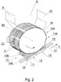
- the hopper 8 is provided with walls 9, 10 ( Fig. 2 ), underneath the hopper 8 there is situated a grooved drum conveyor 11 for conveying the rod-like articles 3D, the circumferential surface 11A of the drum conveyor 11 constitutes the bottom of the hopper 8 (for the sake of simplification, in Fig.
- the circumferential surface 11A is shown as smooth).
- the rod-like articles 3D are transported in grooves 14.
- a circular knife 12 adapted to cut the rod-like article 3D transported on the drum 11 into two rod-like articles 3.
- the rod-like article 3D was shown as a cigarette of a double length which is cut into two individual cigarettes.
- the rod-like article 3D may be any other article, for example a multi-segment filter rod of a double length.
- the drum conveyor 11 is fed from the hopper 8, whereas it is possible to feed the drum conveyor 11 also another way, for example from another drum conveyor.
- the rod-like articles 3 formed by cutting the rod-like article 3D are further transported in the grooves 14 from which the rod-like articles 3 are transferred onto the trays 13 of a transport unit 15 of a forming and transporting apparatus 5.
- the grooves 14 are grouped in sections 14A on the circumferential surface 11A of the drum conveyor 11, whereas the number of the grooves 14 in the section 14A is adapted to the number of grooves in the tray 13.
- the tray 13 consists of two parts and is composed of a first transport section 13A permanently attached to a transport carriage 16 of the transport unit 15 and a second transport section 13B rotatably attached to the first transport section 13A.
- the arrows show the direction of rotation of the drum conveyor 11 and the direction of movement of the transport units 15 along the path 17.
- the transport sections 13A, 13B, the transport carriage 16 and the path 17 were shown in simplified terms, in other drawings they may be shown in another way.
- Fig. 2 shows two transport units 15, 15', whereas the tray 13' of the transport unit 15' has received the rod-like articles 3, whereas the transfer of the rod-like articles 3 onto the tray 13 of the transport unit 15 is just beginning.
- the forming and transporting apparatus 5 may be provided with multiple transport units 15 moving along the path 17 independently of one another.
- the transport sections 13A, 13B are in the open configuration, they are situated so that the grooves 18 of both sections 13A, 13B are in one plane, whereas the groove 18 has a diameter adapted to the diameter of the rod-like article 3, and the axis X of the rod-like article 3 substantially overlaps the axis Y of the groove 18, whereas the axes Y of the grooves 18 are situated in one plane k.
- the second transport section 13B is adapted to rotate around the axis 20 as shown by the arrow R.
- the transport sections 13A, 13B After the rotation of the second transport section 13B by 180°, the transport sections 13A, 13B are in the closed configuration, the plane of the grooves of the section 13B will be situated parallel to the plane of the grooves of the section 13A.
- the groove 18 is provided with openings 19 supplying the vacuum necessary to hold the rod-like article 3 in the groove 18.
- Fig. 3 shows the first transport section 13A unfilled, while all grooves 18 of the second transport section 13B are filled with the rod-like articles 3.
- the openings 19 supplying the vacuum may be provided in both the first transport section 13A and the second transport section 13B.
- the second transport section 13B is situated on the left side and is adapted to make a clockwise rotation R, and the axis of rotation 20 corresponds to the direction of movement T. It is possible to arrange the transport sections reversely, i.e. to situate the second transport section 13B on the right side and to make an anticlockwise rotation.
- Fig. 4 shows an embodiment of the transport unit 15 in the open configuration, just before changing to the closed configuration, moving in the direction T which is parallel to the path 17, whereas the second transport section 13B is on the right side when looking in the direction of movement T.
- the path 17 is shaped as endless, i.e. the transport units 15 move on a closed path.
- the transport sections 13A, 13B of the transport unit 15 are adapted to a change of configuration of their reciprocal position during the shift of the transport unit 15 by the forming unit 25.
- the first section 13A and the second section 13B are rotatably connected on the axis 20 by means of pivots 21, 22.
- the second transport section 13B is provided with a steering element 23, for example it may be a rotating roller (the steering element 23 is visible in Fig. 5 ).
- the steering element 23 is adapted to work with a closing cam 24 of the forming unit 25.
- the closing cam 24 is designed in such a way that the raceway extends over a cylindrical surface.
- the steering element 23 comes into contact with the raceway 24C of the part 24A of the closing cam 24 and with the raceway 24D of the part 24B, which forces the second transport section 13B to make a rotational movement relative to the first transport section 13A in the direction marked with the arrow L.
- the steering element 23 moves in the channel 26 formed by the raceways 24C and 24D of the parts 24A and 24B, respectively, of the closing cam 24 as shown in Fig. 5 , whereas the movement of the steering element 23 only on the raceway 24C is sufficient to force the rotation of the second transport section 13B.
- Fig. 6 shows the transport sections 13A, 13B before inserting into the forming unit 25, i.e. before beginning the rotational movement of the second transport section 13B.
- the closing cam 24 and the steering element 23 are shown diagrammatically with a broken line.
- FIG. 7 shows transport sections 13A and 13B inside the forming unit 25 during the rotation of the second transport section 13B.
- the inlet opening 28A of the channel 28 for the vacuum is situated in a lengthwise caving 29 in the cylindrical outer surface 27A of the body 27.
- the caving 29 together with the outlet opening 28A of the channel 28 directed towards the cylindrical surface 31 are moved before the openings 30 on the cylindrical surface 31 ( Fig. 7 ) which come to the vacuum channel 32.
- the vacuum channel 32 is situated on the closing cam 24 and runs substantially parallel to the channel 26 in which the steering element 23 is moving, and on the cylindrical surface 31 there are situated several openings 30 which connect the vacuum channel 32 with the cylindrical surface 31 and through which the vacuum is supplied to the caving 29, and through the channel 28, the chamber 33 and the channels 34 to the openings 19. At the vacuum channel 32 there is situated an inlet 35 to which the vacuum is supplied.
- the shape of the vacuum channel 32 and the arrangement of the openings 30 corresponding to the course of the channel 26, thus to the path of movement of the channel 28, ensure that the transport section 13B is continuously supplied with the vacuum when making a rotation and shifting the transport unit 15 by the forming unit 25.
- the vacuum channel 32 having the cylindrical surface 31 is fastened to the stationary closing cam 24.
- the vacuum channel 32 may be fastened as stationary independently of the closing cam 24.
- Fig. 8 shows the transport unit 15 after the second section 13B has made a rotation by 180° after passing through the forming unit 25, the rod-like articles 3 transported in the grooves 18 of the transport sections 13A and 13B are formed in the group G which comprises two layers of the rod-like articles 3.
- the movable transport sections 13A, 13B are situated next to each other ( Fig. 6 ) so that the planes k, k' in which lie the axes of the grooves of both transport sections 13A, 13B overlap.
- the planes k, k' of both transport sections 13A, 13B are situated parallel to each other at a distance equal to about one diameter of the rod-like article 3.
- Fig. 1 shows one transport section 15 filled with the rod-like articles 3 and situated before the forming unit 25, and one transport unit 15 in which the group G of the rod-like articles 3 is situated behind the forming unit 25.
- the transport carriages 16 of the forming and transporting apparatus 5 are driven by means of an electric or magnetic drive mechanism which enables the transport units 15 to move independently of one another with different speeds.
- the Beckhoff's XTS drive may be used. Due to the fact that the transport carriages 16 move independently of one another, it is possible to situate the transport carriages 16 as shown in Fig. 2 , i.e. so that the transport trays 13, 13' are adjacent to one another and it is possible to transfer the rod-like articles 3 from the drum conveyor 11 to the grooves 18 continuously, i.e. without stopping the drum conveyor 11.
- the transport unit 15 After passing through the forming unit 25, the transport unit 15 is conveyed to the area in which the group G of the rod-like articles 3 may be transferred to the pockets 40 of the conveyor 6 of the groups of rod-like articles.
- the pockets 40 are pivotally connected with one another like chain links.
- Successive transport units 15 carrying the groups G stand one after another as shown in Fig. 1 on both sides of the conveyor 6.
- the transport unit 15-1 is situated directly opposite the pocket 40-1, the transport unit 15-2 directly opposite the pocket 40-3, the transport unit 15-4 directly opposite the pocket 40-5.
- the group G in the transport unit 15-1 will be transferred to the pocket 40-1 by means of a pushing unit 41-1.
- the group G in the transport unit 15-2 will be transferred to the pocket 40-3 by means of the pushing unit 41-3.
- the group G in the transport unit 15-4 will be transferred to the pocket 40-5 by means of the pushing unit 41-5.
- the transport unit 15-3 there is the group G containing defective rod-like articles 3.
- the group G will be pushed out of the transport unit 15-3 by means of the pushing unit 41-4, whereas an individual pusher 43 of the pushing unit 41-4 and 41-2 is shorter than an individual pusher 42 of the pushing unit 41-1, 41-3, 41-5, and the group G-1 pushed out of the transport unit 15-3 is not placed into the pocket 40-4.
- the transport unit 15'-1 is situated directly opposite the pocket 40-2, the transport unit 15'-2 directly opposite the pocket 40-4, the transport unit 15'-3 directly opposite the pocket 40-6.
- the group G in the transport unit 15'-1 will be transferred to the pocket 40-2 by means of the pushing unit 41'-1.
- the group G in the transport unit 15'-2 will be transferred to the pocket 40-4 by means of the pushing unit 41'-3.
- the group G in the transport unit 15'-3 will be transferred to the pocket 40-6 by means of the pushing unit 41'-5.
- the transferring unit 7 and 7' is activated.
- the transferring unit 7 transfers the groups G from the forming and transporting apparatus 5, and the transferring unit 7' transfers the groups G from the forming and transporting apparatus 5'.
- FIG. 10 shows the transferring units 7, 7' after conveying six groups G to the pockets 40 of the conveyor 6, while the group G-1 containing defective rod-like articles will fall down into an unshown container and will not be fed to the packing apparatus 1.
- the drives of the transferring units 7, 7' were not shown.
- the transport units 15 move further on the path 17, and their transport sections 13A, 13B are in the closed configuration.
- the transport sections 13A, 13B will be switched from the closed configuration to the open configuration after shifting by an opening unit 53 ( Fig. 1 ) which is provided with an opening cam 54 which will force a rotation of the steering element 23, thus a movement of the transport section 13B.
- the action of the opening unit 53 is opposite to the action of the forming unit 25.
- the opening unit 53 may be situated both at the lower section of the path 17 as shown in Fig.1 and at the upper section of the path 17 i.e. behind the transferring unit 7, 7' of before the feeding unit 4, 4'.
- Each of the forming and transporting apparatuses 5, 5' is provided with sensors 50 to check the transported rod-like articles 3 transversely to the axis of these articles.
- the sensors 50 are adapted to receive the radiation passing through the rod-like articles 3 and are situated above the path 17; the not shown sources of radiation are situated beneath the path 17.
- the forming and transporting apparatus 5, 5' is provided with sensors 51, 52 to check the quality of tips of the rod-like articles 3.
- the sensors 51, 52 are situated on both sides of the path 17, 17'. If defective rod-like articles 3 in the groups G are detected, it is possible to reject such group as described above.
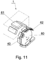
- the transport pockets 40 of the conveyor 6 are moved to the packing apparatus 1.
- the transport pockets 40 are placed onto a transport wheel 60 ( Fig. 11 ).
- the conveyor 6 and the transport wheel 60 make a rotational stroke movement.
- the transport wheel 60 stops when for example three filled transport pockets 40 are situated directly opposite the packing channels 61.
- the pushers 62 push the groups G of the rod-like articles 3 from the transport pockets 40 to the packing channels 61.
- the transport wheel 60 After pushing the groups G of the rod-like articles 3, the transport wheel 60 makes a rotation by a determined angle so that the successive three filled transport pockets 40 will be situated directly opposite the packing channels 61.
Description
- The object of the invention is a forming and transporting apparatus for conveying and forming a group of rod-like articles, and a feeding apparatus for feeding a group of rod-like articles.
- The invention belongs to the tobacco industry solutions, in particular to the field of solutions used in packing machines for finished tobacco products.
- From the document
US 2012/0090954 an apparatus for the handling of objects is known. This apparatus comprises a handling apparatus which receives objects from a feeding area and which supplies the objects by means of a transferring apparatus to at least one workstation. The handling apparatus, respectively, simultaneously receives a specific number of objects by means of an object carrier in such a way that the transferring apparatus has multiple carrying elements for multiple objects respectively held by the handling apparatus. Furthermore, the sequence of movements of each carrying element on the transferring apparatus is individually controlled so that the handling apparatus removes respectively multiple objects from the respective carrying element after passing through at least one workstation. - From the document
US7165668 an apparatus for transferring rod-like articles from a longitudinal conveyor is known, whereas such apparatus transfers the articles onto a transverse conveyor. Furthermore, the apparatus comprises a conveyor which receives the articles from the longitudinal conveyor and supplies the articles to the transverse conveyor, whereas the conveyor comprises at least a first conveying element and a separate second transporting element which are configured for being functionally combined with each other. Additionally, the second conveying element is structured and positioned so that it rotates the articles by a specific angle. Furthermore, the second conveying element is structured and positioned so as to reduce the transport speed of the articles. - From the document
WO2003051718 a cigarette packing machine, comprising an endless drying conveyor having at least one substantially spiral part, an input station and an output station, is known. This conveyor moves endlessly along a given path in a given direction of movement in order to feed successive cigarette batches between the said input and output stations. The apparatus is characterised in that the said drying conveyor comprises a sequence of coils out of which the first said coil extends in the said direction of movement from the said input station and is connected, at the input station, to the last-mentioned coil running through the said output station. - From the document
EP1020357 a method for forming groups of rod-like articles with a determined orientation of the rod-like articles in the group is known. The rod-like articles are supplied through multiple channels, and layers of the three-layer group of rod-like articles are placed into the pockets of an endless pocket conveyor, and the groups of rod-like articles are transferred for packaging. - Apparatuses and methods for rotating oppositely oriented rod-like articles are known from the prior art.
- From the document
US2988199 an apparatus for rotating oppositely oriented rod-like articles with the use of a double-sided V-belt is known. The V-belt is provided with wedges adapted to receive the rod-like articles from a drum feeder, secured against the possibility of rod-like article falling out of the wedge. The rod-like articles, individually placed in the wedges, are rotated in the axis corresponding to the direction of movement of the rod-like articles, due to a twist of the belt on the transmission rollers. The rotated rod-like articles are released individually from the wedges onto a belt feeder which forms them into an oriented flow of the rod-like articles. - From the document
US2929489 an apparatus for rotating oppositely oriented cut rod-like articles is known. In the rod-like article cutting process, two flows with opposite orientations are obtained. In order to unify the orientation, one of the belt conveyors is provided with a crossed transfer belt which enables the rod-like articles arranged one after another to rotate by 180 degrees in the axis corresponding to the direction of movement of the rod-like articles, as a result of which a common orientation for both parallel flows is obtained. A similar solution was shown in the documentGB1015562 - From the document
GB1519293 - From the document
US4860880 an apparatus for rotating a multi-layer flow of rod-like articles is known. The apparatus comprises belt conveyors on which oppositely oriented rod-like articles are situated. By controlling the conveyor travel speed, multi-layer flows of rod-like articles with opposite orientations are created, whereas such flows are rotated, by means of appropriately twisted belts, by the angle of 90 degrees in the axis corresponding to the direction of movement of the rod-like articles. The correctly oriented flows obtained in this way merge and form a mass flow. During a further transport, the mass flow may be rotated again to set the desired orientation. - The object of the invention is a forming and transporting apparatus for conveying rod-like articles and for forming a group of the rod-like articles of the tobacco industry, comprising transport units, whereas a transport unit comprises a transport carriage adapted to move along a path, and a transport tray provided with a number of transport grooves adapted to hold the rod-like articles, whereas such tray is fastened to the transport carriage, whereas the transport carriage is divided into two transport sections which are adapted to change their reciprocal position between an open configuration in which the transport grooves are situated substantially in one plane and a closed configuration in which the transport grooves are situated in two planes being substantially parallel to each other, whereas the transport sections are rotatably connected with each other on the axis of rotation corresponding to the direction of movement of the transport carriage, characterised in that the first transport section is fastened to the transport carriage, and the second transport section is provided with a steering element, the forming and transporting apparatus is provided with a forming unit comprising a closing cam situated next to the path, the closing cam having a raceway adapted to guide the steering element in such a way that when moving the transport unit through the forming unit the second transport section makes a rotation relative to the first transport section in order to change the configuration of the transport sections from the open configuration to the closed configuration.
- The apparatus is further characterised in that the cam has a cylindrical form.
- The apparatus is further characterised in that the steering element is a rotating roller.
- The apparatus is further characterised in that the body of the second tray is provided with at least one vacuum channel being in fluid connection with vacuum openings in the transport grooves of the second transport section, whereas the vacuum channel is directed towards the cylindrical surface provided with openings which supply the vacuum during the movement of the transport unit through the forming unit.
- The apparatus is further characterised in that the cylindrical surface is a stationary surface.
- The apparatus is further characterised by being provided with an opening unit comprising an opening cam situated next to the path, the opening cam having a channel adapted to guide the steering element in such a way that when moving the transport unit through the opening unit the second transport section makes a rotation relative to the first transport section in order to change the configuration of the transport sections from the closed configuration to the open configuration.
- The apparatus is further characterised in that the transport units are adapted to move along a path independently of one another.
- The object of the invention is also a feeding apparatus for feeding a group of rod-like articles, comprising at least one feeding unit for feeding rod-like articles provided with a drum conveyor; at least one forming and transporting apparatus for receiving the rod-like articles from the drum conveyor, conveying the rod-like articles and forming groups of rod-like articles; a conveyor of groups of rod-like articles for receiving the groups of rod-like articles from the forming and transporting apparatus and feeding the groups to a receiving apparatus; a transferring unit for transferring the groups of the rod-like articles from the transport unit to the pockets of the conveyor of the groups of rod-like articles, characterised by being provided with the forming and transport apparatus.
- The use of transport units provided with transport means rotated by means of a cam ensures an increase of the efficiency of production lines. The applied solution allows building a production line with a compact structure. The electromagnetically driven transport carriages as well as rotating and closing sections of the transport trays allow achieving an efficiency which is unachievable for transport systems based on conventional endless chains.
- The forming apparatus according to the invention allows controlling the quality of the rod-like articles with regard to the front surfaces of both ends as well as the components of the articles.
- Furthermore, the forming means according to the invention eliminate the need of inserting the tobacco industry articles into a conventional hopper used in conventional packing machines, which results in a reduction of the number of damaged articles in packets and a reduction of the number of rejected packets with tobacco products.
- The object of the invention was discussed in detail on the basis of an embodiment illustrated in a drawing in which:
- Fig. 1
- shows a fragment of a production line in a perspective view,
- Fig. 2
- shows, in simplified terms, a drum conveyor and a transport unit in a perspective view,
- Fig. 3
- shows, in simplified terms, the transport unit in the open configuration,
- Fig. 4
- shows a forming unit and a transport unit in the open configuration in a perspective view,
- Fig. 5
- shows the forming unit and the transport unit of
Fig. 3 in the open configuration in a perspective view from below, - Fig. 6
- shows the transport unit in the open configuration in the direction of movement of such unit,
- Fig. 7
- shows the transport unit during a change of configuration from open to closed in the direction of movement of such unit,
- Fig. 8
- shows the transport unit in the closed configuration in a side view,
- Fig. 9
- shows fragments of two forming and transporting apparatuses, a fragment of a conveyor of groups of rod-like articles and two transferring units before transferring the groups of rod-like articles,
- Fig. 10
- shows fragments of two forming and transporting apparatuses, a fragment of the conveyor of groups of rod-like articles and two transferring units after transferring the groups of rod-like articles,
- Fig. 11
- diagrammatically shows a packing apparatus and a fragment of the conveyor of the groups of rod-like articles.
-
Fig. 1 shows a fragment of a production line comprising apacking apparatus 1 for packing groups of rod-like articles 3 and afeeding apparatus 2 adapted to feed the groups G of rod-like articles 3. Thefeeding apparatus 2 is provided with twofeeding units 4, 4' for feeding rod-like articles 3D (the rod-like article 3D has the length of two rod-like articles 3), two forming and transportingapparatuses 5, 5' for forming and conveying the groups G of rod-like articles 3 and aconveyor 6 of the groups G of rod-like articles 3 which supplies the groups G of rod-like articles 3 to thepacking apparatus 1, whereas for transferring the groups G of rod-like articles 3 from the forming and transportingapparatus 5, 5' to theconveyor 6 of the groups G a transferringunit 7, 7' is used. The further description concerns such a line as shown inFig. 1 as well as a production line provided with only onefeeding unit 4, one forming and transportingapparatus 5, theconveyor 6 of the groups G of rod-like articles 3 and thepacking apparatus 1. - The
feeding unit 4 is provided with ahopper 8 to which achannel 8A supplying the rod-like articles 3D is attached to thehopper 8 from above or from the side. Thechannel 8A may be situated vertically or slantwise to the vertical direction. The rod-like articles 3D fed to thehopper 8 have a double length in relation to the rod-like articles 3 which are transported by the forming and transportingapparatus 5, 5' from which the formed groups G are fed to thepacking apparatus 1. Thehopper 8 is provided withwalls 9, 10 (Fig. 2 ), underneath thehopper 8 there is situated agrooved drum conveyor 11 for conveying the rod-like articles 3D, thecircumferential surface 11A of thedrum conveyor 11 constitutes the bottom of the hopper 8 (for the sake of simplification, inFig. 1 thecircumferential surface 11A is shown as smooth). The rod-like articles 3D are transported ingrooves 14. Next to thedrum conveyor 11, there is situated acircular knife 12 adapted to cut the rod-like article 3D transported on thedrum 11 into two rod-like articles 3. For example, inFig. 2 the rod-like article 3D was shown as a cigarette of a double length which is cut into two individual cigarettes. The rod-like article 3D may be any other article, for example a multi-segment filter rod of a double length. - The
drum conveyor 11 is fed from thehopper 8, whereas it is possible to feed thedrum conveyor 11 also another way, for example from another drum conveyor. On thedrum conveyor 11, the rod-like articles 3 formed by cutting the rod-like article 3D are further transported in thegrooves 14 from which the rod-like articles 3 are transferred onto thetrays 13 of atransport unit 15 of a forming and transportingapparatus 5. Thegrooves 14 are grouped insections 14A on thecircumferential surface 11A of thedrum conveyor 11, whereas the number of thegrooves 14 in thesection 14A is adapted to the number of grooves in thetray 13. Thetray 13 consists of two parts and is composed of afirst transport section 13A permanently attached to atransport carriage 16 of thetransport unit 15 and asecond transport section 13B rotatably attached to thefirst transport section 13A. The arrows show the direction of rotation of thedrum conveyor 11 and the direction of movement of thetransport units 15 along thepath 17. Thetransport sections transport carriage 16 and thepath 17 were shown in simplified terms, in other drawings they may be shown in another way.Fig. 2 shows twotransport units 15, 15', whereas the tray 13' of the transport unit 15' has received the rod-like articles 3, whereas the transfer of the rod-like articles 3 onto thetray 13 of thetransport unit 15 is just beginning. The forming and transportingapparatus 5 may be provided withmultiple transport units 15 moving along thepath 17 independently of one another. InFig. 3 , thetransport sections grooves 18 of bothsections groove 18 has a diameter adapted to the diameter of the rod-like article 3, and the axis X of the rod-like article 3 substantially overlaps the axis Y of thegroove 18, whereas the axes Y of thegrooves 18 are situated in one plane k. Thesecond transport section 13B is adapted to rotate around theaxis 20 as shown by the arrow R. After the rotation of thesecond transport section 13B by 180°, thetransport sections section 13B will be situated parallel to the plane of the grooves of thesection 13A. Thegroove 18 is provided withopenings 19 supplying the vacuum necessary to hold the rod-like article 3 in thegroove 18.Fig. 3 shows thefirst transport section 13A unfilled, while allgrooves 18 of thesecond transport section 13B are filled with the rod-like articles 3. Theopenings 19 supplying the vacuum may be provided in both thefirst transport section 13A and thesecond transport section 13B. - In
Fig. 3 , looking in the direction of movement T of the transport carriage, thesecond transport section 13B is situated on the left side and is adapted to make a clockwise rotation R, and the axis ofrotation 20 corresponds to the direction of movement T. It is possible to arrange the transport sections reversely, i.e. to situate thesecond transport section 13B on the right side and to make an anticlockwise rotation.Fig. 4 shows an embodiment of thetransport unit 15 in the open configuration, just before changing to the closed configuration, moving in the direction T which is parallel to thepath 17, whereas thesecond transport section 13B is on the right side when looking in the direction of movement T. As shown inFig. 1 , thepath 17 is shaped as endless, i.e. thetransport units 15 move on a closed path. Thetransport sections transport unit 15 are adapted to a change of configuration of their reciprocal position during the shift of thetransport unit 15 by the formingunit 25. Thefirst section 13A and thesecond section 13B are rotatably connected on theaxis 20 by means ofpivots second transport section 13B is provided with asteering element 23, for example it may be a rotating roller (thesteering element 23 is visible inFig. 5 ). Thesteering element 23 is adapted to work with aclosing cam 24 of the formingunit 25. Theclosing cam 24 is designed in such a way that the raceway extends over a cylindrical surface. During the movement of thetransport unit 15 in the open configuration, thesteering element 23 comes into contact with theraceway 24C of thepart 24A of theclosing cam 24 and with theraceway 24D of thepart 24B, which forces thesecond transport section 13B to make a rotational movement relative to thefirst transport section 13A in the direction marked with the arrow L. Thesteering element 23 moves in thechannel 26 formed by theraceways parts closing cam 24 as shown inFig. 5 , whereas the movement of thesteering element 23 only on theraceway 24C is sufficient to force the rotation of thesecond transport section 13B. During the shift of thetransport unit 15 by the formingunit 25, thetransport section 13B rotates in an accelerated movement so that the force of inertia acting on the rod-like articles 3 presses them against thegrooves 18 in order to prevent the rod-like articles 3 from falling out of thegrooves 18 during the rotation of thesecond transport section 13B. In addition, the rod-like articles 3 may be held by the vacuum supplied to theopenings 19 through the channels in thebody 27 of thetransport section 13B.Fig. 6 shows thetransport sections unit 25, i.e. before beginning the rotational movement of thesecond transport section 13B. Theclosing cam 24 and thesteering element 23 are shown diagrammatically with a broken line.Fig. 7 showstransport sections unit 25 during the rotation of thesecond transport section 13B. As shown inFig. 5 , the inlet opening 28A of thechannel 28 for the vacuum is situated in a lengthwise caving 29 in the cylindricalouter surface 27A of thebody 27. During the movement of thetransport unit 15 during the rotational movement of thetransport section 13B, the caving 29 together with the outlet opening 28A of thechannel 28 directed towards thecylindrical surface 31 are moved before theopenings 30 on the cylindrical surface 31 (Fig. 7 ) which come to thevacuum channel 32. Thevacuum channel 32 is situated on theclosing cam 24 and runs substantially parallel to thechannel 26 in which thesteering element 23 is moving, and on thecylindrical surface 31 there are situatedseveral openings 30 which connect thevacuum channel 32 with thecylindrical surface 31 and through which the vacuum is supplied to the caving 29, and through thechannel 28, thechamber 33 and thechannels 34 to theopenings 19. At thevacuum channel 32 there is situated aninlet 35 to which the vacuum is supplied. The shape of thevacuum channel 32 and the arrangement of theopenings 30 corresponding to the course of thechannel 26, thus to the path of movement of thechannel 28, ensure that thetransport section 13B is continuously supplied with the vacuum when making a rotation and shifting thetransport unit 15 by the formingunit 25. Thevacuum channel 32 having thecylindrical surface 31 is fastened to thestationary closing cam 24. Thevacuum channel 32 may be fastened as stationary independently of theclosing cam 24. -
Fig. 8 shows thetransport unit 15 after thesecond section 13B has made a rotation by 180° after passing through the formingunit 25, the rod-like articles 3 transported in thegrooves 18 of thetransport sections like articles 3. In the open configuration, themovable transport sections Fig. 6 ) so that the planes k, k' in which lie the axes of the grooves of bothtransport sections transport sections like article 3.Fig. 1 shows onetransport section 15 filled with the rod-like articles 3 and situated before the formingunit 25, and onetransport unit 15 in which the group G of the rod-like articles 3 is situated behind the formingunit 25. - The
transport carriages 16 of the forming and transportingapparatus 5 are driven by means of an electric or magnetic drive mechanism which enables thetransport units 15 to move independently of one another with different speeds. For this purpose, the Beckhoff's XTS drive may be used. Due to the fact that thetransport carriages 16 move independently of one another, it is possible to situate thetransport carriages 16 as shown inFig. 2 , i.e. so that thetransport trays 13, 13' are adjacent to one another and it is possible to transfer the rod-like articles 3 from thedrum conveyor 11 to thegrooves 18 continuously, i.e. without stopping thedrum conveyor 11. - After passing through the forming
unit 25, thetransport unit 15 is conveyed to the area in which the group G of the rod-like articles 3 may be transferred to thepockets 40 of theconveyor 6 of the groups of rod-like articles. Thepockets 40 are pivotally connected with one another like chain links.Successive transport units 15 carrying the groups G stand one after another as shown inFig. 1 on both sides of theconveyor 6. Threetransport units 15 of the transporting and formingapparatus 5 and three transport units 15' of the transporting and forming apparatus 5' shown inFig. 9 were stopped so that the groups G of the rod-like articles 3 held in these units may be transferred to sixpockets 40 of theconveyor 6, whereas the transfer takes place in a direction perpendicular to the direction of movement T of thetransport units 15 and simultaneously in a direction perpendicular to the direction of movement P of thepockets 40. The transport unit 15-1 is situated directly opposite the pocket 40-1, the transport unit 15-2 directly opposite the pocket 40-3, the transport unit 15-4 directly opposite the pocket 40-5. The group G in the transport unit 15-1 will be transferred to the pocket 40-1 by means of a pushing unit 41-1. The group G in the transport unit 15-2 will be transferred to the pocket 40-3 by means of the pushing unit 41-3. The group G in the transport unit 15-4 will be transferred to the pocket 40-5 by means of the pushing unit 41-5. In the transport unit 15-3, there is the group G containing defective rod-like articles 3. The group G will be pushed out of the transport unit 15-3 by means of the pushing unit 41-4, whereas anindividual pusher 43 of the pushing unit 41-4 and 41-2 is shorter than anindividual pusher 42 of the pushing unit 41-1, 41-3, 41-5, and the group G-1 pushed out of the transport unit 15-3 is not placed into the pocket 40-4. The transport unit 15'-1 is situated directly opposite the pocket 40-2, the transport unit 15'-2 directly opposite the pocket 40-4, the transport unit 15'-3 directly opposite the pocket 40-6. The group G in the transport unit 15'-1 will be transferred to the pocket 40-2 by means of the pushing unit 41'-1. The group G in the transport unit 15'-2 will be transferred to the pocket 40-4 by means of the pushing unit 41'-3. The group G in the transport unit 15'-3 will be transferred to the pocket 40-6 by means of the pushing unit 41'-5. After positioning thetransport units 15, 15' carrying the groups G and after stopping theconveyor 6 of the groups G so that thetransport units 15, 15' are situated directly opposite theempty pockets 40 of theconveyor 6, the transferringunit 7 and 7' is activated. The transferringunit 7 transfers the groups G from the forming and transportingapparatus 5, and the transferring unit 7' transfers the groups G from the forming and transporting apparatus 5'.Fig. 10 shows the transferringunits 7, 7' after conveying six groups G to thepockets 40 of theconveyor 6, while the group G-1 containing defective rod-like articles will fall down into an unshown container and will not be fed to thepacking apparatus 1. InFig. 9 and10 , the drives of the transferringunits 7, 7' were not shown. After conveying the groups G to thepockets 40 of theconveyor 6, thetransport units 15 move further on thepath 17, and theirtransport sections transport sections Fig. 1 ) which is provided with anopening cam 54 which will force a rotation of thesteering element 23, thus a movement of thetransport section 13B. The action of theopening unit 53 is opposite to the action of the formingunit 25. Theopening unit 53 may be situated both at the lower section of thepath 17 as shown inFig.1 and at the upper section of thepath 17 i.e. behind the transferringunit 7, 7' of before thefeeding unit 4, 4'. - Each of the forming and transporting
apparatuses 5, 5' is provided withsensors 50 to check the transported rod-like articles 3 transversely to the axis of these articles. Thesensors 50 are adapted to receive the radiation passing through the rod-like articles 3 and are situated above thepath 17; the not shown sources of radiation are situated beneath thepath 17. Furthermore, the forming and transportingapparatus 5, 5' is provided withsensors like articles 3. Thesensors path 17, 17'. If defective rod-like articles 3 in the groups G are detected, it is possible to reject such group as described above. - The transport pockets 40 of the
conveyor 6 are moved to thepacking apparatus 1. The transport pockets 40 are placed onto a transport wheel 60 (Fig. 11 ). Theconveyor 6 and thetransport wheel 60 make a rotational stroke movement. Thetransport wheel 60 stops when for example three filledtransport pockets 40 are situated directly opposite the packingchannels 61. Thepushers 62 push the groups G of the rod-like articles 3 from the transport pockets 40 to thepacking channels 61. After pushing the groups G of the rod-like articles 3, thetransport wheel 60 makes a rotation by a determined angle so that the successive three filledtransport pockets 40 will be situated directly opposite the packingchannels 61.
Claims (8)
- A forming and transporting apparatus (5) for conveying rod-like articles (3) and forming a group (G) of rod-like articles (3) of the tobacco industry, comprisingtransport units (15), whereas a transport unit (15) comprisesa transport carriage (16) adapted to move along a path (17), anda transport tray (13) provided with a number of transport grooves (18) adapted to hold the rod-like articles (3), whereas such tray is fastened to the transport carriage (16),whereasthe transport carriage (13) is divided into two transport sections (13A, 13B) which are adapted to change their reciprocal position between an open configuration in which the transport grooves (18) are situated substantially in one plane (k, k') and a closed configuration in which the transport grooves (18) are situated in two planes (k, k') being substantially parallel to each other,whereasthe transport sections (13A, 13B) are rotatably connected with each other on the axis of rotation (20) corresponding to the direction (T) of movement of the transport carriage (16),characterised in thatthe first transport section (13A) is fastened to the transport carriage (16), and the second transport section (13B) is provided with a steering element (23),the forming and transporting apparatus (5) is provided with a forming unit (25) comprising a closing cam (24) situated next to the path (17), the closing cam (24) having a raceway (24C) adapted to guide the steering element (23) in such a way that while moving the transport unit (15) through the forming unit (25) the second transport section (13B) makes a rotation relative to the first transport section (13A) in order to change the configuration of the transport sections (13A, 13B) from the open configuration to the closed configuration.
- The apparatus as in claim 1 characterised in that the closing cam (24) has a cylindrical form.
- The apparatus as in claim 1 or 2 characterised in that the steering element (23) is a rotating roller.
- The apparatus as in any of the preceding claims characterised in that the body (27) of the second tray (13B) is provided with at least one vacuum channel (28) being in fluid connection with vacuum openings (19) in the transport grooves (18) of the second transport section (13B), whereas the vacuum channel (28) is directed towards the cylindrical surface (31) provided with openings (30) which supply the vacuum during the movement of the transport unit (15) through the forming unit (25).
- The apparatus as in claim 4 characterised in that the cylindrical surface (31) is a stationary surface.
- The apparatus as in any of the preceding claims characterised by being provided with an opening unit (53) comprising an opening cam (54) situated next to the path (17), the opening cam (54) having a channel adapted to guide the steering element (23) in such a way that while moving the transport unit (15) through the opening unit (53) the second transport section (13B) makes a rotation relative to the first transport section (13A) in order to change the configuration of the transport sections (13A, 13B) from the closed configuration to the open configuration.
- The apparatus as in any of the preceding claims characterised in that the transport units (15) are adapted to move along the path (17) independently of one another.
- A feeding apparatus for feeding a group (G) of rod-like articles comprising at least one feeding unit (4) for feeding the rod-like articles (3D) provided with a drum conveyor (12); at least one forming and transporting apparatus (15) for receiving the rod-like articles (3) from the drum conveyor (11), conveying the rod-like articles (3) and forming the groups (G) of the rod-like articles (3); a conveyor (6) of groups of the rod-like articles (3) for receiving the groups (G) of the rod-like articles from the forming and transporting apparatus (5) and feeding the groups (G) to a receiving apparatus; a transferring unit (7) for transferring the groups (G) of the rod-like articles (3) from the transport units (15) to the pockets (40) of the conveyor (6) of the groups of rod-like articles,
characterised in that
the feeding apparatus is provided with the forming and transporting apparatus described in any of the claims 1 to 7.
Priority Applications (8)
| Application Number | Priority Date | Filing Date | Title |
|---|---|---|---|
| EP19154649.8A EP3689760B1 (en) | 2019-01-31 | 2019-01-31 | Forming and transporting apparatus for conveying and forming a group of rod-likes articles, and feeding apparatus for feeding a group of rod-like articles |
| PL19154649T PL3689760T3 (en) | 2019-01-31 | 2019-01-31 | Forming and transporting apparatus for conveying and forming a group of rod-likes articles, and feeding apparatus for feeding a group of rod-like articles |
| RU2020100242A RU2020100242A (en) | 2019-01-31 | 2020-01-10 | FORMING AND TRANSPORTING DEVICE FOR MOVING AND FORMING A GROUP OF ROD-SHAPED PRODUCTS AND FEEDING DEVICE FOR FEEDING A GROUP OF ROD-SHAPED PRODUCTS |
| US15/929,204 US10842183B2 (en) | 2019-01-31 | 2020-01-15 | Forming and transporting apparatus for conveying and forming a group of rod-like articles, and feeding apparatus for feeding a group of rod-like articles |
| JP2020006961A JP2020125157A (en) | 2019-01-31 | 2020-01-20 | Forming and transporting apparatus for transporting and forming group of rod-shaped articles, and feeding apparatus for feeding group of rod-shaped articles |
| CN202010068281.XA CN111493355A (en) | 2019-01-31 | 2020-01-20 | Forming and transporting device for conveying and forming rod-shaped article groups and feeding device for feeding rod-shaped article groups |
| KR1020200010657A KR20200096146A (en) | 2019-01-31 | 2020-01-29 | Forming and transporting apparatus for conveying and forming a group of rod-like articles, and feeding apparatus for feeding a group of rod-like articles |
| BR102020002111-7A BR102020002111A2 (en) | 2019-01-31 | 2020-01-31 | TRAINING AND TRANSPORTATION EQUIPMENT TO TRANSPORT SIMILAR ARTICLES TO STEMS AND FORM A GROUP OF SIMILAR ARTICLES TO STEMS IN THE TOBACCO INDUSTRY AND FEEDING APPLIANCE TO FEED A GROUP OF SIMILAR ARTICLES TO STEMS |
Applications Claiming Priority (1)
| Application Number | Priority Date | Filing Date | Title |
|---|---|---|---|
| EP19154649.8A EP3689760B1 (en) | 2019-01-31 | 2019-01-31 | Forming and transporting apparatus for conveying and forming a group of rod-likes articles, and feeding apparatus for feeding a group of rod-like articles |
Publications (2)
| Publication Number | Publication Date |
|---|---|
| EP3689760A1 EP3689760A1 (en) | 2020-08-05 |
| EP3689760B1 true EP3689760B1 (en) | 2021-09-15 |
Family
ID=65861189
Family Applications (1)
| Application Number | Title | Priority Date | Filing Date |
|---|---|---|---|
| EP19154649.8A Active EP3689760B1 (en) | 2019-01-31 | 2019-01-31 | Forming and transporting apparatus for conveying and forming a group of rod-likes articles, and feeding apparatus for feeding a group of rod-like articles |
Country Status (8)
| Country | Link |
|---|---|
| US (1) | US10842183B2 (en) |
| EP (1) | EP3689760B1 (en) |
| JP (1) | JP2020125157A (en) |
| KR (1) | KR20200096146A (en) |
| CN (1) | CN111493355A (en) |
| BR (1) | BR102020002111A2 (en) |
| PL (1) | PL3689760T3 (en) |
| RU (1) | RU2020100242A (en) |
Families Citing this family (3)
| Publication number | Priority date | Publication date | Assignee | Title |
|---|---|---|---|---|
| CN112607072A (en) * | 2020-12-29 | 2021-04-06 | 西华大学 | Powder cavity filling device |
| CN113942825B (en) * | 2021-09-09 | 2023-03-28 | 山东华滋自动化技术股份有限公司 | Plunger paste finished product transferring and conveying device |
| WO2023198711A1 (en) * | 2022-04-11 | 2023-10-19 | Philip Morris Products S.A. | Aerosol-generating article collation forming with increased number of hoppers |
Family Cites Families (22)
| Publication number | Priority date | Publication date | Assignee | Title |
|---|---|---|---|---|
| US2701938A (en) * | 1951-11-30 | 1955-02-15 | Arthur J Murray | Method and apparatus for packaging cans and bottles in carrier cartons |
| US2929489A (en) | 1956-05-04 | 1960-03-22 | American Mach & Foundry | Cigarette turn around device |
| US2988199A (en) | 1958-12-01 | 1961-06-13 | American Mach & Foundry | Cigarete turn around device |
| GB1015562A (en) | 1963-06-18 | 1966-01-05 | Zd Y V I Plzen | Method and device for turning cigarettes delivered from a cigarette making machine |
| US3589097A (en) * | 1969-05-27 | 1971-06-29 | Amf Inc | Cigarette packers |
| US3884013A (en) * | 1970-10-02 | 1975-05-20 | British & Foreign Tobacco Co | Method of assembling and filling hinged containers |
| GB1519293A (en) | 1975-09-30 | 1978-07-26 | Molins Ltd | Conveying cigarettes and other rod like articles |
| JPS567820A (en) | 1979-05-22 | 1981-01-27 | Molins Ltd | Transfer system of barrlike material such as tobacco |
| DE3141476C2 (en) * | 1981-10-20 | 1986-01-16 | Mannesmann AG, 4000 Düsseldorf | Stacking machine for nested stacking of profiled rolled bars |
| US4931131A (en) * | 1989-06-02 | 1990-06-05 | Thompson Ralph F | Package collator machine |
| US5174089A (en) * | 1989-08-07 | 1992-12-29 | Danieli & C. Officine Meccaniche Spa | Method to package sections and rotary packaging machine that employs the method |
| IT1266373B1 (en) | 1993-05-31 | 1996-12-27 | Gd Spa | METHOD FOR OBTAINING A MASS FLOW OF EQUALLY-ORIENTED CIGARETTES. |
| DE29605419U1 (en) * | 1996-03-23 | 1996-05-30 | Topack Verpacktech Gmbh | Receiving pocket of a chamber belt for transporting blocks of rod-shaped articles |
| IT1308976B1 (en) | 1999-01-15 | 2002-01-15 | Gd Spa | METHOD FOR FORMING GROUPS OF CIGARETTES IN A CIGARETTE PACKING MACHINE. |
| ITBO20010766A1 (en) | 2001-12-18 | 2003-06-18 | Gd Spa | CIGARETTE PACKING MACHINE |
| US7070039B2 (en) | 2003-09-16 | 2006-07-04 | Hauni Maschinenbau Ag | Apparatus and method for the transfer of rod-shaped articles |
| US7165668B2 (en) | 2003-10-21 | 2007-01-23 | Hauni Maschinenbau Ag | Apparatus and method for the delivery of rod-shaped articles |
| ES2321324T3 (en) * | 2004-11-05 | 2009-06-04 | Meadwestvaco Packaging Systems Llc | PROCEDURE AND EQUIPMENT TO BUILD A BOX OF CARTON. |
| DE102006045508B3 (en) | 2006-09-27 | 2007-12-27 | Joimax Gmbh | Bone cutter manufacturing method, involves determining tube periphery of cutter-shaft, determining middle desired tooth height of cutter-toothing, and determining desired tooth period length of cutter-toothing from desired tooth height |
| US20080199296A1 (en) * | 2007-02-20 | 2008-08-21 | Ghosh Pradip K | Bundling system for long products |
| DE102009027462A1 (en) | 2009-07-03 | 2011-01-05 | Robert Bosch Gmbh | Device for handling objects |
| DK2602204T5 (en) * | 2011-12-05 | 2014-07-14 | Indag Ges Für Industriebedarf Mbh & Co Betr S Kg | Carton for packaging of bag-like beverage containers, machine for closing a package and method for closing a package |
-
2019
- 2019-01-31 EP EP19154649.8A patent/EP3689760B1/en active Active
- 2019-01-31 PL PL19154649T patent/PL3689760T3/en unknown
-
2020
- 2020-01-10 RU RU2020100242A patent/RU2020100242A/en unknown
- 2020-01-15 US US15/929,204 patent/US10842183B2/en active Active
- 2020-01-20 CN CN202010068281.XA patent/CN111493355A/en active Pending
- 2020-01-20 JP JP2020006961A patent/JP2020125157A/en active Pending
- 2020-01-29 KR KR1020200010657A patent/KR20200096146A/en unknown
- 2020-01-31 BR BR102020002111-7A patent/BR102020002111A2/en not_active IP Right Cessation
Also Published As
| Publication number | Publication date |
|---|---|
| PL3689760T3 (en) | 2022-01-03 |
| BR102020002111A2 (en) | 2020-08-11 |
| KR20200096146A (en) | 2020-08-11 |
| EP3689760A1 (en) | 2020-08-05 |
| RU2020100242A (en) | 2021-07-12 |
| CN111493355A (en) | 2020-08-07 |
| US20200245673A1 (en) | 2020-08-06 |
| US10842183B2 (en) | 2020-11-24 |
| JP2020125157A (en) | 2020-08-20 |
Similar Documents
| Publication | Publication Date | Title |
|---|---|---|
| US10842183B2 (en) | Forming and transporting apparatus for conveying and forming a group of rod-like articles, and feeding apparatus for feeding a group of rod-like articles | |
| US7341141B2 (en) | Method and unit for grouping products | |
| EP0496046A1 (en) | Apparatus for conveying and grouping products | |
| EP0695703A1 (en) | Apparatus for conveying products in groups | |
| US6213284B1 (en) | Method and unit for transferring articles | |
| JPH02296617A (en) | Temporarily halting method of driven conveyor and its apparatus | |
| EP3837175B1 (en) | Transport conveyor, transport apparatus and packing apparatus | |
| US5070994A (en) | Process and apparatus for transferring articles fed on a single track onto several discharge tracks | |
| EP1388507B1 (en) | Method and device for forming groups of products | |
| EP3704959B1 (en) | Method of feeding a packer for rod-like articles of tobacco industry and feeding apparatus for feeding a group of rod-like articles to a packer for rod-like articles | |
| EP3003930B1 (en) | Feeder device of products with reduced longitudinal dimensions in machines for the tobacco industry | |
| EP3837176B1 (en) | Transport device for rod-like articles of the tobacco industry | |
| GB2155886A (en) | Method and apparatus for manufacturing hygiene articles | |
| US20160075459A1 (en) | Method and device for handling elongated articles | |
| PL242036B1 (en) | Forming and transport device for moving and forming a group of rod-like articles and a feeding device for feeding a group of rod-like articles | |
| PL242037B1 (en) | Feeding method for the packing machine of rod-like articles of the tobacco industry and the feeding device for feeding a group of rod-like articles to the packing machine of rod-like articles | |
| EP3836805B1 (en) | Method and apparatus for conversion of moving stream of oppositely oriented rod-like articles | |
| JPH09278165A (en) | Lining-up device | |
| USRE26357E (en) | Metering apparatus | |
| KR102467040B1 (en) | Method and apparatus for conveying rod-like articles of tobacco industry | |
| CN113692386B (en) | Conveyor for a device for continuously transporting objects and method for continuously transporting objects | |
| JP3661126B2 (en) | Article conveying device | |
| US6364091B1 (en) | Conveying device for forming and conveying groups of products | |
| JP6734415B1 (en) | Alignment device | |
| JP2014105069A (en) | Transfer device and transfer method |
Legal Events
| Date | Code | Title | Description |
|---|---|---|---|
| PUAI | Public reference made under article 153(3) epc to a published international application that has entered the european phase |
Free format text: ORIGINAL CODE: 0009012 |
|
| STAA | Information on the status of an ep patent application or granted ep patent |
Free format text: STATUS: THE APPLICATION HAS BEEN PUBLISHED |
|
| AK | Designated contracting states |
Kind code of ref document: A1 Designated state(s): AL AT BE BG CH CY CZ DE DK EE ES FI FR GB GR HR HU IE IS IT LI LT LU LV MC MK MT NL NO PL PT RO RS SE SI SK SM TR |
|
| AX | Request for extension of the european patent |
Extension state: BA ME |
|
| STAA | Information on the status of an ep patent application or granted ep patent |
Free format text: STATUS: REQUEST FOR EXAMINATION WAS MADE |
|
| 17P | Request for examination filed |
Effective date: 20210205 |
|
| RBV | Designated contracting states (corrected) |
Designated state(s): AL AT BE BG CH CY CZ DE DK EE ES FI FR GB GR HR HU IE IS IT LI LT LU LV MC MK MT NL NO PL PT RO RS SE SI SK SM TR |
|
| GRAP | Despatch of communication of intention to grant a patent |
Free format text: ORIGINAL CODE: EPIDOSNIGR1 |
|
| STAA | Information on the status of an ep patent application or granted ep patent |
Free format text: STATUS: GRANT OF PATENT IS INTENDED |
|
| INTG | Intention to grant announced |
Effective date: 20210630 |
|
| GRAS | Grant fee paid |
Free format text: ORIGINAL CODE: EPIDOSNIGR3 |
|
| GRAA | (expected) grant |
Free format text: ORIGINAL CODE: 0009210 |
|
| STAA | Information on the status of an ep patent application or granted ep patent |
Free format text: STATUS: THE PATENT HAS BEEN GRANTED |
|
| AK | Designated contracting states |
Kind code of ref document: B1 Designated state(s): AL AT BE BG CH CY CZ DE DK EE ES FI FR GB GR HR HU IE IS IT LI LT LU LV MC MK MT NL NO PL PT RO RS SE SI SK SM TR |
|
| REG | Reference to a national code |
Ref country code: CH Ref legal event code: EP |
|
| REG | Reference to a national code |
Ref country code: DE Ref legal event code: R096 Ref document number: 602019007609 Country of ref document: DE |
|
| REG | Reference to a national code |
Ref country code: IE Ref legal event code: FG4D |
|
| REG | Reference to a national code |
Ref country code: AT Ref legal event code: REF Ref document number: 1430353 Country of ref document: AT Kind code of ref document: T Effective date: 20211015 |
|
| REG | Reference to a national code |
Ref country code: LT Ref legal event code: MG9D |
|
| REG | Reference to a national code |
Ref country code: NL Ref legal event code: MP Effective date: 20210915 |
|
| PG25 | Lapsed in a contracting state [announced via postgrant information from national office to epo] |
Ref country code: LT Free format text: LAPSE BECAUSE OF FAILURE TO SUBMIT A TRANSLATION OF THE DESCRIPTION OR TO PAY THE FEE WITHIN THE PRESCRIBED TIME-LIMIT Effective date: 20210915 Ref country code: BG Free format text: LAPSE BECAUSE OF FAILURE TO SUBMIT A TRANSLATION OF THE DESCRIPTION OR TO PAY THE FEE WITHIN THE PRESCRIBED TIME-LIMIT Effective date: 20211215 Ref country code: HR Free format text: LAPSE BECAUSE OF FAILURE TO SUBMIT A TRANSLATION OF THE DESCRIPTION OR TO PAY THE FEE WITHIN THE PRESCRIBED TIME-LIMIT Effective date: 20210915 Ref country code: NO Free format text: LAPSE BECAUSE OF FAILURE TO SUBMIT A TRANSLATION OF THE DESCRIPTION OR TO PAY THE FEE WITHIN THE PRESCRIBED TIME-LIMIT Effective date: 20211215 Ref country code: FI Free format text: LAPSE BECAUSE OF FAILURE TO SUBMIT A TRANSLATION OF THE DESCRIPTION OR TO PAY THE FEE WITHIN THE PRESCRIBED TIME-LIMIT Effective date: 20210915 Ref country code: SE Free format text: LAPSE BECAUSE OF FAILURE TO SUBMIT A TRANSLATION OF THE DESCRIPTION OR TO PAY THE FEE WITHIN THE PRESCRIBED TIME-LIMIT Effective date: 20210915 Ref country code: RS Free format text: LAPSE BECAUSE OF FAILURE TO SUBMIT A TRANSLATION OF THE DESCRIPTION OR TO PAY THE FEE WITHIN THE PRESCRIBED TIME-LIMIT Effective date: 20210915 |
|
| REG | Reference to a national code |
Ref country code: AT Ref legal event code: MK05 Ref document number: 1430353 Country of ref document: AT Kind code of ref document: T Effective date: 20210915 |
|
| PG25 | Lapsed in a contracting state [announced via postgrant information from national office to epo] |
Ref country code: LV Free format text: LAPSE BECAUSE OF FAILURE TO SUBMIT A TRANSLATION OF THE DESCRIPTION OR TO PAY THE FEE WITHIN THE PRESCRIBED TIME-LIMIT Effective date: 20210915 Ref country code: GR Free format text: LAPSE BECAUSE OF FAILURE TO SUBMIT A TRANSLATION OF THE DESCRIPTION OR TO PAY THE FEE WITHIN THE PRESCRIBED TIME-LIMIT Effective date: 20211216 |
|
| PG25 | Lapsed in a contracting state [announced via postgrant information from national office to epo] |
Ref country code: AT Free format text: LAPSE BECAUSE OF FAILURE TO SUBMIT A TRANSLATION OF THE DESCRIPTION OR TO PAY THE FEE WITHIN THE PRESCRIBED TIME-LIMIT Effective date: 20210915 |
|
| PG25 | Lapsed in a contracting state [announced via postgrant information from national office to epo] |
Ref country code: IS Free format text: LAPSE BECAUSE OF FAILURE TO SUBMIT A TRANSLATION OF THE DESCRIPTION OR TO PAY THE FEE WITHIN THE PRESCRIBED TIME-LIMIT Effective date: 20220115 Ref country code: SM Free format text: LAPSE BECAUSE OF FAILURE TO SUBMIT A TRANSLATION OF THE DESCRIPTION OR TO PAY THE FEE WITHIN THE PRESCRIBED TIME-LIMIT Effective date: 20210915 Ref country code: SK Free format text: LAPSE BECAUSE OF FAILURE TO SUBMIT A TRANSLATION OF THE DESCRIPTION OR TO PAY THE FEE WITHIN THE PRESCRIBED TIME-LIMIT Effective date: 20210915 Ref country code: RO Free format text: LAPSE BECAUSE OF FAILURE TO SUBMIT A TRANSLATION OF THE DESCRIPTION OR TO PAY THE FEE WITHIN THE PRESCRIBED TIME-LIMIT Effective date: 20210915 Ref country code: PT Free format text: LAPSE BECAUSE OF FAILURE TO SUBMIT A TRANSLATION OF THE DESCRIPTION OR TO PAY THE FEE WITHIN THE PRESCRIBED TIME-LIMIT Effective date: 20220117 Ref country code: NL Free format text: LAPSE BECAUSE OF FAILURE TO SUBMIT A TRANSLATION OF THE DESCRIPTION OR TO PAY THE FEE WITHIN THE PRESCRIBED TIME-LIMIT Effective date: 20210915 Ref country code: ES Free format text: LAPSE BECAUSE OF FAILURE TO SUBMIT A TRANSLATION OF THE DESCRIPTION OR TO PAY THE FEE WITHIN THE PRESCRIBED TIME-LIMIT Effective date: 20210915 Ref country code: EE Free format text: LAPSE BECAUSE OF FAILURE TO SUBMIT A TRANSLATION OF THE DESCRIPTION OR TO PAY THE FEE WITHIN THE PRESCRIBED TIME-LIMIT Effective date: 20210915 Ref country code: CZ Free format text: LAPSE BECAUSE OF FAILURE TO SUBMIT A TRANSLATION OF THE DESCRIPTION OR TO PAY THE FEE WITHIN THE PRESCRIBED TIME-LIMIT Effective date: 20210915 Ref country code: AL Free format text: LAPSE BECAUSE OF FAILURE TO SUBMIT A TRANSLATION OF THE DESCRIPTION OR TO PAY THE FEE WITHIN THE PRESCRIBED TIME-LIMIT Effective date: 20210915 |
|
| REG | Reference to a national code |
Ref country code: DE Ref legal event code: R097 Ref document number: 602019007609 Country of ref document: DE |
|
| PLBE | No opposition filed within time limit |
Free format text: ORIGINAL CODE: 0009261 |
|
| STAA | Information on the status of an ep patent application or granted ep patent |
Free format text: STATUS: NO OPPOSITION FILED WITHIN TIME LIMIT |
|
| PG25 | Lapsed in a contracting state [announced via postgrant information from national office to epo] |
Ref country code: DK Free format text: LAPSE BECAUSE OF FAILURE TO SUBMIT A TRANSLATION OF THE DESCRIPTION OR TO PAY THE FEE WITHIN THE PRESCRIBED TIME-LIMIT Effective date: 20210915 |
|
| 26N | No opposition filed |
Effective date: 20220616 |
|
| PG25 | Lapsed in a contracting state [announced via postgrant information from national office to epo] |
Ref country code: SI Free format text: LAPSE BECAUSE OF FAILURE TO SUBMIT A TRANSLATION OF THE DESCRIPTION OR TO PAY THE FEE WITHIN THE PRESCRIBED TIME-LIMIT Effective date: 20210915 Ref country code: MC Free format text: LAPSE BECAUSE OF FAILURE TO SUBMIT A TRANSLATION OF THE DESCRIPTION OR TO PAY THE FEE WITHIN THE PRESCRIBED TIME-LIMIT Effective date: 20210915 |
|
| REG | Reference to a national code |
Ref country code: CH Ref legal event code: PL |
|
| REG | Reference to a national code |
Ref country code: BE Ref legal event code: MM Effective date: 20220131 |
|
| PG25 | Lapsed in a contracting state [announced via postgrant information from national office to epo] |
Ref country code: LU Free format text: LAPSE BECAUSE OF NON-PAYMENT OF DUE FEES Effective date: 20220131 |
|
| PG25 | Lapsed in a contracting state [announced via postgrant information from national office to epo] |
Ref country code: FR Free format text: LAPSE BECAUSE OF NON-PAYMENT OF DUE FEES Effective date: 20220131 Ref country code: BE Free format text: LAPSE BECAUSE OF NON-PAYMENT OF DUE FEES Effective date: 20220131 |
|
| PG25 | Lapsed in a contracting state [announced via postgrant information from national office to epo] |
Ref country code: LI Free format text: LAPSE BECAUSE OF NON-PAYMENT OF DUE FEES Effective date: 20220131 Ref country code: CH Free format text: LAPSE BECAUSE OF NON-PAYMENT OF DUE FEES Effective date: 20220131 |
|
| PG25 | Lapsed in a contracting state [announced via postgrant information from national office to epo] |
Ref country code: IE Free format text: LAPSE BECAUSE OF NON-PAYMENT OF DUE FEES Effective date: 20220131 |
|
| PGFP | Annual fee paid to national office [announced via postgrant information from national office to epo] |
Ref country code: PL Payment date: 20230104 Year of fee payment: 5 Ref country code: IT Payment date: 20230120 Year of fee payment: 5 Ref country code: DE Payment date: 20230123 Year of fee payment: 5 |
|
| P01 | Opt-out of the competence of the unified patent court (upc) registered |
Effective date: 20230418 |
|
| GBPC | Gb: european patent ceased through non-payment of renewal fee |
Effective date: 20230131 |
|
| PG25 | Lapsed in a contracting state [announced via postgrant information from national office to epo] |
Ref country code: GB Free format text: LAPSE BECAUSE OF NON-PAYMENT OF DUE FEES Effective date: 20230131 |