EP3689752B1 - Flugzeughilfstriebwerk (apu) mit geschwindigkeitskompensation - Google Patents
Flugzeughilfstriebwerk (apu) mit geschwindigkeitskompensation Download PDFInfo
- Publication number
- EP3689752B1 EP3689752B1 EP20154043.2A EP20154043A EP3689752B1 EP 3689752 B1 EP3689752 B1 EP 3689752B1 EP 20154043 A EP20154043 A EP 20154043A EP 3689752 B1 EP3689752 B1 EP 3689752B1
- Authority
- EP
- European Patent Office
- Prior art keywords
- apu
- rotational speed
- variable rotational
- aircraft
- electrical load
- Prior art date
- Legal status (The legal status is an assumption and is not a legal conclusion. Google has not performed a legal analysis and makes no representation as to the accuracy of the status listed.)
- Active
Links
Images





Classifications
-
- B—PERFORMING OPERATIONS; TRANSPORTING
- B64—AIRCRAFT; AVIATION; COSMONAUTICS
- B64D—EQUIPMENT FOR FITTING IN OR TO AIRCRAFT; FLIGHT SUITS; PARACHUTES; ARRANGEMENT OR MOUNTING OF POWER PLANTS OR PROPULSION TRANSMISSIONS IN AIRCRAFT
- B64D41/00—Power installations for auxiliary purposes
-
- B—PERFORMING OPERATIONS; TRANSPORTING
- B64—AIRCRAFT; AVIATION; COSMONAUTICS
- B64D—EQUIPMENT FOR FITTING IN OR TO AIRCRAFT; FLIGHT SUITS; PARACHUTES; ARRANGEMENT OR MOUNTING OF POWER PLANTS OR PROPULSION TRANSMISSIONS IN AIRCRAFT
- B64D27/00—Arrangement or mounting of power plants in aircraft; Aircraft characterised by the type or position of power plants
- B64D27/02—Aircraft characterised by the type or position of power plants
- B64D27/10—Aircraft characterised by the type or position of power plants of gas-turbine type
-
- B—PERFORMING OPERATIONS; TRANSPORTING
- B64—AIRCRAFT; AVIATION; COSMONAUTICS
- B64D—EQUIPMENT FOR FITTING IN OR TO AIRCRAFT; FLIGHT SUITS; PARACHUTES; ARRANGEMENT OR MOUNTING OF POWER PLANTS OR PROPULSION TRANSMISSIONS IN AIRCRAFT
- B64D31/00—Power plant control systems; Arrangement of power plant control systems in aircraft
-
- B—PERFORMING OPERATIONS; TRANSPORTING
- B64—AIRCRAFT; AVIATION; COSMONAUTICS
- B64D—EQUIPMENT FOR FITTING IN OR TO AIRCRAFT; FLIGHT SUITS; PARACHUTES; ARRANGEMENT OR MOUNTING OF POWER PLANTS OR PROPULSION TRANSMISSIONS IN AIRCRAFT
- B64D31/00—Power plant control systems; Arrangement of power plant control systems in aircraft
- B64D31/02—Initiating means
- B64D31/06—Initiating means actuated automatically
-
- B—PERFORMING OPERATIONS; TRANSPORTING
- B64—AIRCRAFT; AVIATION; COSMONAUTICS
- B64D—EQUIPMENT FOR FITTING IN OR TO AIRCRAFT; FLIGHT SUITS; PARACHUTES; ARRANGEMENT OR MOUNTING OF POWER PLANTS OR PROPULSION TRANSMISSIONS IN AIRCRAFT
- B64D43/00—Arrangements or adaptations of instruments
- B64D43/02—Arrangements or adaptations of instruments for indicating aircraft speed or stalling conditions
-
- B—PERFORMING OPERATIONS; TRANSPORTING
- B64—AIRCRAFT; AVIATION; COSMONAUTICS
- B64D—EQUIPMENT FOR FITTING IN OR TO AIRCRAFT; FLIGHT SUITS; PARACHUTES; ARRANGEMENT OR MOUNTING OF POWER PLANTS OR PROPULSION TRANSMISSIONS IN AIRCRAFT
- B64D45/00—Aircraft indicators or protectors not otherwise provided for
-
- F—MECHANICAL ENGINEERING; LIGHTING; HEATING; WEAPONS; BLASTING
- F01—MACHINES OR ENGINES IN GENERAL; ENGINE PLANTS IN GENERAL; STEAM ENGINES
- F01D—NON-POSITIVE DISPLACEMENT MACHINES OR ENGINES, e.g. STEAM TURBINES
- F01D15/00—Adaptations of machines or engines for special use; Combinations of engines with devices driven thereby
- F01D15/10—Adaptations for driving, or combinations with, electric generators
-
- F—MECHANICAL ENGINEERING; LIGHTING; HEATING; WEAPONS; BLASTING
- F02—COMBUSTION ENGINES; HOT-GAS OR COMBUSTION-PRODUCT ENGINE PLANTS
- F02C—GAS-TURBINE PLANTS; AIR INTAKES FOR JET-PROPULSION PLANTS; CONTROLLING FUEL SUPPLY IN AIR-BREATHING JET-PROPULSION PLANTS
- F02C7/00—Features, components parts, details or accessories, not provided for in, or of interest apart form groups F02C1/00 - F02C6/00; Air intakes for jet-propulsion plants
- F02C7/32—Arrangement, mounting, or driving, of auxiliaries
-
- F—MECHANICAL ENGINEERING; LIGHTING; HEATING; WEAPONS; BLASTING
- F02—COMBUSTION ENGINES; HOT-GAS OR COMBUSTION-PRODUCT ENGINE PLANTS
- F02C—GAS-TURBINE PLANTS; AIR INTAKES FOR JET-PROPULSION PLANTS; CONTROLLING FUEL SUPPLY IN AIR-BREATHING JET-PROPULSION PLANTS
- F02C9/00—Controlling gas-turbine plants; Controlling fuel supply in air- breathing jet-propulsion plants
- F02C9/26—Control of fuel supply
- F02C9/28—Regulating systems responsive to plant or ambient parameters, e.g. temperature, pressure, rotor speed
-
- F—MECHANICAL ENGINEERING; LIGHTING; HEATING; WEAPONS; BLASTING
- F02—COMBUSTION ENGINES; HOT-GAS OR COMBUSTION-PRODUCT ENGINE PLANTS
- F02C—GAS-TURBINE PLANTS; AIR INTAKES FOR JET-PROPULSION PLANTS; CONTROLLING FUEL SUPPLY IN AIR-BREATHING JET-PROPULSION PLANTS
- F02C9/00—Controlling gas-turbine plants; Controlling fuel supply in air- breathing jet-propulsion plants
- F02C9/26—Control of fuel supply
- F02C9/44—Control of fuel supply responsive to the speed of aircraft, e.g. Mach number control, optimisation of fuel consumption
-
- H—ELECTRICITY
- H02—GENERATION; CONVERSION OR DISTRIBUTION OF ELECTRIC POWER
- H02K—DYNAMO-ELECTRIC MACHINES
- H02K7/00—Arrangements for handling mechanical energy structurally associated with dynamo-electric machines, e.g. structural association with mechanical driving motors or auxiliary dynamo-electric machines
- H02K7/18—Structural association of electric generators with mechanical driving motors, e.g. with turbines
- H02K7/1807—Rotary generators
- H02K7/1823—Rotary generators structurally associated with turbines or similar engines
-
- H—ELECTRICITY
- H02—GENERATION; CONVERSION OR DISTRIBUTION OF ELECTRIC POWER
- H02K—DYNAMO-ELECTRIC MACHINES
- H02K7/00—Arrangements for handling mechanical energy structurally associated with dynamo-electric machines, e.g. structural association with mechanical driving motors or auxiliary dynamo-electric machines
- H02K7/18—Structural association of electric generators with mechanical driving motors, e.g. with turbines
- H02K7/1807—Rotary generators
- H02K7/1846—Rotary generators structurally associated with wheels or associated parts
-
- B—PERFORMING OPERATIONS; TRANSPORTING
- B64—AIRCRAFT; AVIATION; COSMONAUTICS
- B64D—EQUIPMENT FOR FITTING IN OR TO AIRCRAFT; FLIGHT SUITS; PARACHUTES; ARRANGEMENT OR MOUNTING OF POWER PLANTS OR PROPULSION TRANSMISSIONS IN AIRCRAFT
- B64D41/00—Power installations for auxiliary purposes
- B64D2041/002—Mounting arrangements for auxiliary power units (APU's)
-
- B—PERFORMING OPERATIONS; TRANSPORTING
- B64—AIRCRAFT; AVIATION; COSMONAUTICS
- B64D—EQUIPMENT FOR FITTING IN OR TO AIRCRAFT; FLIGHT SUITS; PARACHUTES; ARRANGEMENT OR MOUNTING OF POWER PLANTS OR PROPULSION TRANSMISSIONS IN AIRCRAFT
- B64D2221/00—Electric power distribution systems onboard aircraft
-
- F—MECHANICAL ENGINEERING; LIGHTING; HEATING; WEAPONS; BLASTING
- F05—INDEXING SCHEMES RELATING TO ENGINES OR PUMPS IN VARIOUS SUBCLASSES OF CLASSES F01-F04
- F05D—INDEXING SCHEME FOR ASPECTS RELATING TO NON-POSITIVE-DISPLACEMENT MACHINES OR ENGINES, GAS-TURBINES OR JET-PROPULSION PLANTS
- F05D2220/00—Application
- F05D2220/50—Application for auxiliary power units (APU's)
-
- F—MECHANICAL ENGINEERING; LIGHTING; HEATING; WEAPONS; BLASTING
- F05—INDEXING SCHEMES RELATING TO ENGINES OR PUMPS IN VARIOUS SUBCLASSES OF CLASSES F01-F04
- F05D—INDEXING SCHEME FOR ASPECTS RELATING TO NON-POSITIVE-DISPLACEMENT MACHINES OR ENGINES, GAS-TURBINES OR JET-PROPULSION PLANTS
- F05D2220/00—Application
- F05D2220/70—Application in combination with
- F05D2220/76—Application in combination with an electrical generator
-
- F—MECHANICAL ENGINEERING; LIGHTING; HEATING; WEAPONS; BLASTING
- F05—INDEXING SCHEMES RELATING TO ENGINES OR PUMPS IN VARIOUS SUBCLASSES OF CLASSES F01-F04
- F05D—INDEXING SCHEME FOR ASPECTS RELATING TO NON-POSITIVE-DISPLACEMENT MACHINES OR ENGINES, GAS-TURBINES OR JET-PROPULSION PLANTS
- F05D2270/00—Control
- F05D2270/01—Purpose of the control system
- F05D2270/02—Purpose of the control system to control rotational speed (n)
-
- F—MECHANICAL ENGINEERING; LIGHTING; HEATING; WEAPONS; BLASTING
- F05—INDEXING SCHEMES RELATING TO ENGINES OR PUMPS IN VARIOUS SUBCLASSES OF CLASSES F01-F04
- F05D—INDEXING SCHEME FOR ASPECTS RELATING TO NON-POSITIVE-DISPLACEMENT MACHINES OR ENGINES, GAS-TURBINES OR JET-PROPULSION PLANTS
- F05D2270/00—Control
- F05D2270/01—Purpose of the control system
- F05D2270/03—Purpose of the control system in variable speed operation
-
- F—MECHANICAL ENGINEERING; LIGHTING; HEATING; WEAPONS; BLASTING
- F05—INDEXING SCHEMES RELATING TO ENGINES OR PUMPS IN VARIOUS SUBCLASSES OF CLASSES F01-F04
- F05D—INDEXING SCHEME FOR ASPECTS RELATING TO NON-POSITIVE-DISPLACEMENT MACHINES OR ENGINES, GAS-TURBINES OR JET-PROPULSION PLANTS
- F05D2270/00—Control
- F05D2270/01—Purpose of the control system
- F05D2270/05—Purpose of the control system to affect the output of the engine
- F05D2270/053—Explicitly mentioned power
-
- F—MECHANICAL ENGINEERING; LIGHTING; HEATING; WEAPONS; BLASTING
- F05—INDEXING SCHEMES RELATING TO ENGINES OR PUMPS IN VARIOUS SUBCLASSES OF CLASSES F01-F04
- F05D—INDEXING SCHEME FOR ASPECTS RELATING TO NON-POSITIVE-DISPLACEMENT MACHINES OR ENGINES, GAS-TURBINES OR JET-PROPULSION PLANTS
- F05D2270/00—Control
- F05D2270/01—Purpose of the control system
- F05D2270/20—Purpose of the control system to optimize the performance of a machine
-
- F—MECHANICAL ENGINEERING; LIGHTING; HEATING; WEAPONS; BLASTING
- F05—INDEXING SCHEMES RELATING TO ENGINES OR PUMPS IN VARIOUS SUBCLASSES OF CLASSES F01-F04
- F05D—INDEXING SCHEME FOR ASPECTS RELATING TO NON-POSITIVE-DISPLACEMENT MACHINES OR ENGINES, GAS-TURBINES OR JET-PROPULSION PLANTS
- F05D2270/00—Control
- F05D2270/30—Control parameters, e.g. input parameters
- F05D2270/304—Spool rotational speed
-
- F—MECHANICAL ENGINEERING; LIGHTING; HEATING; WEAPONS; BLASTING
- F05—INDEXING SCHEMES RELATING TO ENGINES OR PUMPS IN VARIOUS SUBCLASSES OF CLASSES F01-F04
- F05D—INDEXING SCHEME FOR ASPECTS RELATING TO NON-POSITIVE-DISPLACEMENT MACHINES OR ENGINES, GAS-TURBINES OR JET-PROPULSION PLANTS
- F05D2270/00—Control
- F05D2270/30—Control parameters, e.g. input parameters
- F05D2270/311—Air humidity
-
- F—MECHANICAL ENGINEERING; LIGHTING; HEATING; WEAPONS; BLASTING
- F05—INDEXING SCHEMES RELATING TO ENGINES OR PUMPS IN VARIOUS SUBCLASSES OF CLASSES F01-F04
- F05D—INDEXING SCHEME FOR ASPECTS RELATING TO NON-POSITIVE-DISPLACEMENT MACHINES OR ENGINES, GAS-TURBINES OR JET-PROPULSION PLANTS
- F05D2270/00—Control
- F05D2270/30—Control parameters, e.g. input parameters
- F05D2270/313—Air temperature
-
- F—MECHANICAL ENGINEERING; LIGHTING; HEATING; WEAPONS; BLASTING
- F05—INDEXING SCHEMES RELATING TO ENGINES OR PUMPS IN VARIOUS SUBCLASSES OF CLASSES F01-F04
- F05D—INDEXING SCHEME FOR ASPECTS RELATING TO NON-POSITIVE-DISPLACEMENT MACHINES OR ENGINES, GAS-TURBINES OR JET-PROPULSION PLANTS
- F05D2270/00—Control
- F05D2270/30—Control parameters, e.g. input parameters
- F05D2270/335—Output power or torque
-
- H—ELECTRICITY
- H02—GENERATION; CONVERSION OR DISTRIBUTION OF ELECTRIC POWER
- H02P—CONTROL OR REGULATION OF ELECTRIC MOTORS, ELECTRIC GENERATORS OR DYNAMO-ELECTRIC CONVERTERS; CONTROLLING TRANSFORMERS, REACTORS OR CHOKE COILS
- H02P2101/00—Special adaptation of control arrangements for generators
- H02P2101/30—Special adaptation of control arrangements for generators for aircraft
-
- H—ELECTRICITY
- H02—GENERATION; CONVERSION OR DISTRIBUTION OF ELECTRIC POWER
- H02P—CONTROL OR REGULATION OF ELECTRIC MOTORS, ELECTRIC GENERATORS OR DYNAMO-ELECTRIC CONVERTERS; CONTROLLING TRANSFORMERS, REACTORS OR CHOKE COILS
- H02P9/00—Arrangements for controlling electric generators for the purpose of obtaining a desired output
- H02P9/10—Control effected upon generator excitation circuit to reduce harmful effects of overloads or transients, e.g. sudden application of load, sudden removal of load, sudden change of load
-
- Y—GENERAL TAGGING OF NEW TECHNOLOGICAL DEVELOPMENTS; GENERAL TAGGING OF CROSS-SECTIONAL TECHNOLOGIES SPANNING OVER SEVERAL SECTIONS OF THE IPC; TECHNICAL SUBJECTS COVERED BY FORMER USPC CROSS-REFERENCE ART COLLECTIONS [XRACs] AND DIGESTS
- Y02—TECHNOLOGIES OR APPLICATIONS FOR MITIGATION OR ADAPTATION AGAINST CLIMATE CHANGE
- Y02T—CLIMATE CHANGE MITIGATION TECHNOLOGIES RELATED TO TRANSPORTATION
- Y02T50/00—Aeronautics or air transport
- Y02T50/50—On board measures aiming to increase energy efficiency
Definitions
- the present disclosure relates to an auxiliary power unit (APU) control system for an aircraft. More particularly, the disclosure relates to an APU control system for compensating the rotational speed of the APU to maintain a substantially constant power output.
- APU auxiliary power unit
- An aircraft may be equipped with an auxiliary power unit (APU) in the form of a gas turbine.
- APU auxiliary power unit
- the APU provides electrical power as well as bleed air.
- the bleed air is extracted from the load compressor of the APU.
- the APU is limited to providing bleed air only on the ground and at very low altitudes.
- an electrically propelled aircraft includes an APU that only provides electrical power.
- the APU of an electrically propelled aircraft does not include a load compressor, and therefore does not provide bleed air.
- a gas turbine is usually operated at a steady-state output speed to provide power and, in at least some aircraft, bleed air.
- the performance of a gas turbine is affected by ambient conditions. Specifically, the power output and efficiency of a gas turbine depend upon ambient conditions such as altitude, air temperature, humidity, and air density.
- the reduction in the power output of a gas turbine is proportional to an increase in altitude. As an example, the air density at sea level is about four times denser when compared to 40,000 feet (about 12,192 meters) altitude. A reduction in air density also decreases the air mass flow rate into the gas turbine. Consequently, the gas turbine is only able to produce about one-fourth the power at 40,000 feet (12,192 meters) altitude compared to sea level.
- APUs found in an aircraft are typically oversized to accommodate potential shock loads, which occur when the load demand increases by a significant amount within a very short period of time. More specifically, the turbine is sized to have sufficient rotor inertia so that a shock load does not cause the rotational speed to drop below a predetermined frequency. However, an oversized APU results in increased mass to the aircraft.
- Patent document US 2018/170564 A1 relates to a unit for generating non-propulsive electrical power for use on board an aircraft, the unit comprising an electricity production device comprising a gas turbine and an electricity generator mechanically connected to an outlet shaft of the gas turbine, the electricity generator including output electrical connections for being electrically connected to an electrical power supply network on board an aircraft.
- the unit includes energy storage means and regulator means configured to control the speed of rotation of the gas turbine as a function of the electrical power required by the on-board electrical power supply network.
- an auxiliary power unit (APU) control system for an aircraft according to independent claim 1 is disclosed.
- the APU control system includes an APU drivingly coupled to one or more generators, one or more processors, and a memory coupled to the one or more processors.
- the memory stores data comprising a database and program code that, when executed by the one or more processors, causes the APU control system to receive one or more ambient signals indicative of an air density value and one or more power signals indicative of a specific amount of power generated by the APU.
- the system is further configured to determine a first variable rotational speed of the APU based on the air density value and instruct the APU to operate at the first variable rotational speed.
- the APU continues to generate the specific amount of power when operating at the first variable rotational speed.
- the system After instructing the APU to operate at the first variable rotational speed, the system receives an electrical load signal.
- the electrical load signal is indicative of an electrical load demand by the one or more generators.
- the system is further configured to determine a second variable rotational speed of the APU based on the electrical load demand by the one or more generators and instruct the APU to operate at the second variable rotational speed.
- an aircraft including an APU control system according to the aforementioned first aspect.
- the aircraft comprises the APU and one or more generators drivingly coupled to the APU, where only the one or more generators are provided as a load to the APU.
- the aircraft also includes the memory coupled to the one or more processors.
- the memory stores data comprising the database and program code that, when executed by the one or more processors, causes the APU control system to acquire one or more ambient signals indicative of an air density value and one or more power signals indicative of a specific amount of power generated by the APU.
- the system is further configured to determine a first variable rotational speed of the APU based on the air density value and instruct the APU to operate at the first variable rotational speed.
- the APU continues to generate the specific amount of power when operating at the first variable rotational speed.
- the system acquires an electrical load signal.
- the electrical load signal is indicative of an electrical load demand by the one or more generators.
- the system is further configured to determine a second variable rotational speed of the APU based on the electrical load demand by the one or more generators and instruct the APU to operate at the second variable rotational speed.
- a method of adjusting a variable rotational speed of an APU in an aircraft includes receiving, by a computer, one or more ambient signals indicative of an air density value and one or more power signals indicative of a specific amount of power generated by the APU.
- the method further includes determining, by the computer, a first variable rotational speed of the APU based on the air density value.
- the method also includes instructing the APU to operate at the first variable rotational speed, where the APU continues to generate the specific amount of power when operating at the variable rotational speed.
- the method includes receiving an electrical load signal.
- the electrical load signal is indicative of an electrical load demand by one or more generators drivingly coupled to the APU.
- the method also includes determining, by the computer, a second variable rotational speed of the APU based on the electrical load demand by the one or more generators. Finally, the method includes instructing the APU to operate at the second variable rotational speed.
- the disclosure is directed towards an auxiliary power unit (APU) control system for an aircraft, where the APU is a gas turbine.
- the APU control system varies rotational speed of the APU while maintaining a substantially constant power output, even as ambient conditions and operating parameters of the aircraft that affect the performance of the APU change. Specifically, changes in ambient conditions such as air density, air temperature, humidity, and altitude may adversely affect the performance of the APU. For example, as the aircraft increases in altitude the air density decreases, which in turn reduces the mass flow air provided to the APU.
- the APU control system compensates for the reduction air density by adjusting the rotational speed of the APU. Therefore, the power output of the APU remains substantially constant even as the inlet air density decreases.
- the APU control system may also adjust the rotational speed of the APU based on other ambient conditions such as aircraft velocity and humidity.
- the APU control system also provides rotational speed compensation based on the electrical load demand, which in turn improves the efficiency of the APU. Specifically, during times when there is a full-load demand the rotational speed of the APU is increased, however a lighter load demand allows a reduction in rotational speed of the APU. Accordingly, the disclosed APU control system may require a smaller APU to perform the same function as a conventional system that relies upon a gas turbine that operates at fixed speeds. In one example, the disclosed APU control system may be used in an electrically propelled aircraft or in an aircraft that utilizes electrical power for all non-propulsive systems.
- FIG. 1 a schematic illustration of an auxiliary power unit (APU) control system 18 for an aircraft 20 is shown.
- the APU control system 18 includes an APU 22, one or more generators 24 that are driven by the APU 22, and a control module 28 that is in electrical communication with the APU 22 and the generators 24.
- the APU 22 is a gas turbine configured to convert fuel into mechanical energy.
- FIG. 1 illustrates one or more generators 24 drivingly coupled to the APU 22, it is to be appreciated that other devices may be driven by the APU 22 as well. For example, devices such as air compressors or hydraulic pumps may be drivingly coupled to the APU 22.
- the control module 28 is also in electrical communication with one or more other control modules 40 in the aircraft 20.
- the control modules 40 include a flight computer control module.
- the APU control system 18 dynamically adjusts the rotational speed of the APU 22 based on ambient conditions and operational parameters of the aircraft 20.
- the APU control system 18 includes a speed compensation mode that adjusts the rotational speed of the APU 22 to maintain a substantially constant power output.
- the APU control system 18 also includes a variable speed ground mode, a maintenance mode, or both the variable speed ground mode and the maintenance mode. Both the variable speed ground mode and the maintenance mode are performed only when the aircraft 20 is on ground. However, the speed compensation mode is performed when the aircraft is on ground or is in flight.
- FIG. 2 is a schematic diagram of an exemplary example of the APU 22 and the generators 24.
- the APU 22 includes a power compressor 42, a combustor 44, a power turbine 46, and a load compressor 48 that is drivingly coupled to the APU 22.
- FIG. 2 is merely exemplary in nature and different configurations of gas turbines may be used as well.
- the APU 22 does not include a load compressor. As explained below, the APU 22 shown in FIG.
- the 3 is part of an aircraft that does not provide bleed air to one or more pneumatic loads 68 in the aircraft 20, such as an electrically propelled aircraft or an aircraft that utilizes electrical power for all non-propulsive systems.
- the pneumatic loads 68 include, for example, an environmental control system (ECS) and main engine starting air for one or more main engines.
- ECS environmental control system
- the power compressor 42 draws ambient air A into an inlet 50, compresses the ambient air A, and supplies compressed air to the combustor 44.
- the combustor 44 receives the compressed air from the power compressor 42 and a flow of fuel F from a fuel metering valve 62.
- the fuel F and compressed air are mixed within the combustor 44 and are ignited to produce combustion gas that is supposed to the power turbine 46.
- the combustion gas expands through the power turbine 46 and impinges on the turbine blades (not shown), which causes the power turbine 46 to rotate.
- the power turbine 46 includes an output shaft 64 that drives the power compressor 42, the load compressor 48, and the generators 24.
- the APU 22 is drivingly coupled to the generators 24 by the output shaft 64.
- FIG. 2 illustrates a single-shaft configuration where the output shaft 64 is coupled to the generators 24, in another example a double-shaft configuration may be used instead where separate output shafts are used to drive the generators 24 and the load compressor 48.
- an accessory gearbox may be used to drive the generators 24 and the load compressor 48.
- the load compressor 48 draws the ambient air A into an inlet 66 by a plurality of inlet guide vanes 67, and compresses the ambient air A.
- the compressed ambient air is supplied to the pneumatic loads 68 by a bleed air valve 70.
- a load compressor 48 for providing bleed air to the pneumatic loads 68 in the aircraft 20.
- the APU 22 illustrated in FIG. 3 is used when the aircraft 20 uses electrically powered cabin air compressors (i.e., electrical motors drive the air compressors).
- the generators 24 are connected to the APU 22.
- an electrically driven compressor 72 is included in the aircraft 20 to provide the air required by the pneumatic loads 68.
- the control module 28 is configured to control the overall operation of the APU 22. Specifically, the control module 28 controls the rotational speed of the output shaft 64 of the APU 22 based on various ambient conditions and operating parameters of the aircraft as explained in detail below. It is to be appreciated that the rotational speed of the output shaft 64 of the APU 22 may be controlled based on a rotational speed signal. However, the rotational speed of the output shaft 64 may also be controlled by other operational parameters as well. For example, the control module 28 controls a fuel flow rate to the combustor 44, an electrical power output 38 of the generators 24, or the output power of the output shaft 64 to achieve a particular rotational speed of the output shaft 64.
- the control module 28 receives as input various ambient conditions and data pertaining to the operation of the aircraft 20. Specifically, the control module 28 receives as input one or more ambient signals indicative of an air density value, an ambient humidity signal, an aircraft velocity signal, an electrical load signal 76, a signal indicative of the rotational speed of the APU 22 (which is measured at the output shaft 64), a signal indicative of the output torque of the APU 22 (at the output shaft 64), and one or more flight deck commands.
- the input signals to the control module 28 may be sent from one or more sensors 84 on the aircraft 20 or, alternatively, through the other control modules 40 (e.g., the flight control module).
- the ambient signal indicative of the air density value is a measured value.
- the air density value is measured directly by a sensing device.
- an aneroid barometer may be used to directly measure the air density.
- the air density value is a calculated value.
- the ambient signals indicative of the air density value are a temperature signal and an altitude signal.
- the control module 28 receives as input an air density signal or, alternatively, the temperature signal and the altitude signal. The control module 28 calculates the air density value based on the temperature signal and altitude signal.
- the measured air density value i.e., the air density measured by the aneroid barometer
- the calculated air density value i.e., based on altitude and temperature
- the electrical load signal 76 is determined by the control module 28 or, alternatively, by the other control modules 40 of the aircraft 20.
- the electrical load signal 76 is indicative of an electrical load demand on the generators 24. Characteristics such as excitation current and control are also included in the electrical load signal 76.
- the electrical load signal 76 includes a power transfer pending signal 86 that is received from a generator control module 78.
- the generator control module 78 is connected to one or more main generators 80 of the aircraft 20.
- the main generators 80 are driven by the output shaft 64 of the APU 22.
- the power transfer pending signal 86 indicates a power transfer from the main generators 80 of the aircraft 20 to the generators 24.
- the main generators 80 of the aircraft 20 are driven by main engines 82 of the aircraft 20.
- the electrical load on the generators 24 may transition from a no-load condition (or a relatively light load) to a heavy load.
- the electrical load signal 76 includes the power transfer pending signal 86. Therefore, the control module 28 is configured to adjust operation of the APU 22 in anticipation the heavier loads created by the power transition from the main generators 80.
- variable speed ground mode When the APU control system 18 operates in either of these modes, the aircraft 20 is on ground.
- the APU 22 operates to conserve fuel when operating in the variable speed ground mode.
- the control module 28 determines the aircraft 20 is on ground and at a gate or other waiting area where passengers may board the aircraft 20.
- the control module 28 receives an indication in anticipation of ground support equipment being used on the aircraft 20.
- the control module 28 initiates the variable speed ground mode in response to receiving the indication that the ground support equipment is about to be used.
- Some examples of the ground support equipment include, but are not limited to, vacuum cleaners and aircraft cargo handling equipment.
- the control module 28 instructs the APU 22 to operate at a bandwidth rotational speed.
- the bandwidth rotational speed includes a range of speeds that are compatible with an electrical power supply for aircraft ground support equipment (e.g., the vacuum cleaners and the cargo handling equipment).
- the bandwidth rotational speed is configured to provide power to ground support equipment operating at frequencies ranging from about 370 Hertz to about 440 Hertz, however it is to be appreciated that other ranges may be used as well.
- the APU control system 18 When operating in the maintenance mode, the APU control system 18 performs a health monitoring check of the APU 22.
- the control module 28 first determines that the aircraft 20 is on ground.
- the control module 28 receives an indication that the maintenance mode is to be commenced.
- the control module 28 instructs the APU 22 operate at a user-defined speed.
- the user-defined speed is indicated by a user-generated signal.
- the user-defined speed is a discrete rotational speed or range of speeds determined by an individual such as, for example, a maintenance technician. For example, if an unwanted vibration or resonance is experienced at a specific speed or range of rotational speeds, then the user-generated signal may be set to the specific speed or range of speeds to troubleshoot the APU 22.
- the aircraft 20 includes a load compressor (i.e., the load compressor 48). Unlike the example as illustrated in FIG. 3 , the aircraft 20 in FIG. 2 is configured to provide bleed air to one or more pneumatic loads 68. It is to be appreciated that the speed compensation mode compensates for various ambient and operating parameters of the aircraft 20, which are constantly changing when the aircraft 20 is on ground and in flight. For example, when the aircraft 20 is in the climb stage of flight and is increasing in altitude, the air density and temperature decrease. However, even when the aircraft 20 is not in flight, the air density and temperature may still vary based on the elevation of an airport or terrain where the aircraft 20 is on ground.
- the air density at sea level is about thirty five percent denser at -40°C (-40°F) when compared to a temperature of about 48.9°C (120°F) at the same altitude.
- the APU control system 18 operates in the speed compensation mode, the rotational speed of the APU 22 is varied to compensate for the changing conditions to maintain a substantially constant power output.
- the control module 28 adjusts the rotational speed of the APU 22 based on at least the air density value.
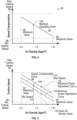
- FIG. 4 is a graph 90 illustrating an exemplary speed compensation curve 88 that represents a relationship between a variable rotational speed of the APU 22 ( FIG. 1 ) and the air density value.
- a minimum value 92 e.g., 0.3 kg/m 3
- compensation of the rotational speed of the APU 22 increases.
- a maximum value 94 e.g., 1.51 kg/m 3
- compensation of the rotational speed of the APU 22 decreases.
- the speed compensation curve 88 includes values that fall between a maximum turbine operating speed 96 and a minimum turbine operating speed 98.
- the speed compensation curve 88 also includes a nominal operating point 100 of the APU 22.
- the variable rotational speed of the APU 22 is inversely proportional to the air density value.
- the control module 28 determines the variable rotational speed of the APU 22 based on an inversely proportional relationship between the variable rotational speed of the APU 22 and the air density value.
- the air density value varies at about a 5 to 1 ratio between a cold day at sea level (1.51 kg/m 3 ) and at 40,000 feet (12,192 meters) altitude (0.3 kg/m 3 ). Therefore, conventional APUs that operate at a constant speed generate about eighty percent less power at high altitude (i.e., 40,000 feet or 12,192 meters) when compared to the power output at sea level.
- the disclosed APU control system 18 compensates for the loss in air density at higher altitudes by increasing the rotational speed.
- the speed compensation curve 88 is linear.
- FIG. 4 is merely exemplary in nature, and the relationship between the variable rotational speed of the APU 22 ( FIG. 1 ) and the air density value may be non-linear instead.
- the specific relationship between the rotational speed of the APU 22 and the air density value is dependent upon the type or model of gas turbine. Therefore, the relationship between the air density and the variable rotational speed varies based on specific characteristics of the gas turbine.
- a single speed compensation curve 88 is shown in FIG. 4 , it is to be appreciated that a family or a plurality of curves may be provided, where each curve corresponds to a particular operating point.
- Some characteristics of a gas turbine that affect the relationship between the air density and variable rotational speed include the geometry or configuration of the air inlet. Moreover, the size, shape, number of rotor blades, number of guide vanes, and number of stages of the power compressor 42 of a gas turbine may also affect the relationship between the air density and variable rotational speed as well.
- the control module 28 receives one or more ambient signals indicative of the air density value and one or more power signals indicative of a specific amount of power generated by the APU 22.
- the ambient signal is either a measured value indicative of the air density value (i.e., measured by an aneroid barometer) or, alternatively, the ambient signal is calculated based on a temperature signal and an altitude signal.
- the power signals include a speed signal that represents the rotational speed of the output shaft 64 and a torque signal indicative of the output torque at the output shaft 64.
- the control module 28 calculates the specific amount of power generated by the APU 22 based on the rotational speed and output torque of the output shaft 64. Alternatively, the control module 28 calculates the power of the output shaft 64 from the voltage and current output of the generators 24.
- the control module 28 determines the variable rotational speed of the APU 22 based on the air density value. Specifically, as seen in FIG. 4 , a specific rotational speed of the APU 22 corresponds to the air density value on the speed compensation curve 88. Once the specific rotational speed of the APU 22 is determined, the control module 28 instructs the APU 22 to operate at the variable rotational speed. The APU 22 continues to generate the specific amount of power when operating at the variable rotational speed. In other words, the control module 28 varies the rotational speed of the APU 22 to maintain a substantially constant power output, even as ambient and operational parameters change. As the air density of the ambient air decreases as the altitude increases the rotational speed of the APU 22 increases proportionally.
- the control module 28 instructs the APU 22 to operate at the variable rotational speed based on a regulating signal 110 that is sent to the APU 22.
- the regulating signal 110 is configured to regulate the rotational speed of the output shaft 64 of the APU 22.
- equivalent control of the APU 22 is achieved by regulating the fuel flow rate to the combustor 44 by controlling the position of the fuel metering valve 62.
- equivalent control of the APU 22 is achieved based on regulating the electrical power output of the generators 24 or by power output of the output shaft 64.
- variable rotational speed of the APU 22 is also dynamically adjusted based on the electrical load demand on the generators 24.
- the control module 28 receives the electrical load signal 76.
- the control module 28 adjusts the variable rotational speed of the APU 22 based on the electrical load demand of the generators 24.
- the rotational speed of the APU 22 is compensated for air density first. For example, in one approach the rotational speed of the APU 22 is compensated based on a high altitude of about 40,000 feet (12,192 meters) first.
- the electrical load demand of the generators 24 may be relatively low. For example, the generators 24 may only be loaded to about twenty percent of the power rating. Therefore, the rotational speed of the APU 22 may then be adjusted (i.e., slowed down) based on the reduced load demand of the generators 24, which in turn increases fuel efficiency.
- FIG. 5 is an illustration of the speed compensation curve 88, an exemplary maximum power adjustment curve 120, and an exemplary minimum power adjustment curve 122.
- the control module 28 is configured to either increase or decrease the variable rotational speed of the APU 22 based on a proportional relationship between the electrical load demand and the variable rotational speed of the APU 22.
- the control module 28 is configured to increase the variable rotational speed of the APU 22 with respect to the speed compensation curve 88 to accommodate an increasing electrical power demand.
- the control module 28 is configured to decrease the variable rotational speed of the APU 22 to accommodate a decreasing electrical power demand with respect to the speed compensation curve 88.
- the control module 28 receives the electrical load signal 76, which indicates the electrical load demand. In some examples, the control module 28 determines the electrical load demand on the generators 24 is increasing. In response to determining the electrical load demand on the generators 24 is increasing, the control module 28 increases the variable rotational speed of the APU 22. Referring specifically to FIG. 5 , the control module 28 may continue to increase the variable rotational speed of the APU 22 at a given air density value 130 until the variable rotational speed is at a maximum rotational speed 132.
- control module 28 is configured to incrementally adjust the variable rotational speed of the APU 22 at a given air density value to maintain a specific amount of power currently being generated by the APU 22.
- the maximum rotational speed 132 is located along the maximum power adjustment curve 120.
- the maximum rotational speed 132 of the APU 22 correlates to a maximum electrical power demand threshold.
- control module 28 determines the electrical load demand on generators 24 is decreasing. In response to determining the electrical load demand of the generators 24 is decreasing, the control module 28 decreases the variable rotational speed of the APU 22. Specifically, as seen in FIG. 5 , the control module 28 may continue to decrease the variable rotational speed of the APU 22 at the given air density value 130 until the variable rotational speed of the APU 22 is at a minimum rotational speed 134.
- the minimum rotational speed 134 is located along the minimum power adjustment curve 122, and correlates to a minimum electrical power demand threshold.
- control module 28 dynamically adjust the variable rotational speed of the APU 22 at the given air density value 130 proportionally based on the magnitude of the electrical load demand, where the variable rotational speed of the APU 22 is adjustable between the minimum rotational speed 134 and the maximum rotational speed 132.
- the minimum rotational speed 134 corresponds to the minimum electrical power demand threshold of the generators 24 and the maximum rotational speed 132 corresponds to the maximum electrical power demand threshold of the generators 24.
- the values of the maximum electrical power demand threshold and the minimum electrical power demand threshold depend upon one or more of the following factors: a specific type or model of aircraft, a size of the generators 24, a maximum power output of the generators 24, a power factor of the generators 24, a load type of devices that are supplied with electrical power by the generators 24, and a combination of loads that result in the maximum electrical power demand and the minimum electrical power demand thresholds.
- the types of loads that may be supplied electrical power by the generators 24 include resistive loads and reactive loads (i.e., loads that include an electrical motor and require more power to initially start).
- the maximum electrical power demand threshold ranges from about sixty to about eighty percent of the maximum power output of the generators 24, and the minimum electrical power demand threshold ranges from about twenty to about forty percent of the maximum power output of the generators 24, however it is to be appreciated that these values are merely exemplary in nature.
- the maximum and minimum electrical power demand thresholds are determined based on a look-up table.
- the maximum and minimum electrical power demand thresholds vary based on the flight plan of the aircraft 20.
- the maximum power adjustment curve 120 and the minimum power adjustment curve 122 both follow the speed compensation curve 88.
- both the maximum power adjustment curve 120 and the minimum power adjustment curve 122 vary in value by the same amount as the speed compensation curve 88.
- the value of the maximum power adjustment curve 120 and the minimum power adjustment curve 122 may vary at different rates when compared to the speed compensation curve 88 as well.
- the maximum power adjustment curve 120, the minimum power adjustment curve 122, and the speed compensation curve 88 may each include a different slope.
- the speed compensation curve 88 is non-linear, and the corresponding maximum power adjustment curve 120 and minimum power adjustment curve 122 are non-linear as well.
- FIG. 6 is a graph 128 illustrating an exemplary turbine speed curve 138 of the APU 22.
- the turbine speed curve 138 is determined based on engine model simulation as well as test data. It is to be appreciated that the turbine speed curve 138 shown in FIG. 6 is merely exemplary in nature, and the specific profile of the turbine speed curve varies on factors such as, but not limited to, turbine size and the number of spools.
- relatively lower altitudes 140 e.g., about sea level to about 2,000 feet or 609.6 meters
- an increase in rotational speed of the APU 22 results in a greater increase in power when compared to an identical increase in rotational speed of the APU at relatively higher altitudes 142.
- Relatively higher altitudes include maximum altitude values, which include any value over about 35,000 feet (10,668 meters). For example, increase the rotational speed of the APU 22 from about ten percent to about twenty-three percent at the relatively lower altitudes 140 results in twenty percent more power output. In contrast, increase the rotational speed of the APU 22 by about forty percent engine speed at the relatively higher altitudes 142 results in the same power increase (i.e., twenty percent).
- the turbine speed curve 138 varies based on ambient conditions such as aircraft velocity and humidity. Therefore, the turbine speed curve 138 is re-calculated based on ambient conditions.
- control module 28 adjusts the variable rotational speed of the APU based on a flight plan of the aircraft 20.
- the flight plan is stored in memory of the flight control module and is sent to the control module 28.
- the control module 28 is configured to calculate an anticipated or predicted electrical load based on the flight plan, where the predicted electrical load is based on flight control surface demands that modify hydraulic loads of the aircraft 20.
- the control module 28 adjusts the variable rotational speed of the APU 22 based on the predicted electrical load.
- flight control surface commands such as, but not limited to, flap deploy and retract, thrust reverse, and auto-gap flap actuation increase or decrease the hydraulic load of an aircraft.
- Auto-gap flap actuation represents an automatic flap movement function that is based on an angle of attack, an air speed, and flap position of the aircraft 20.
- an electrically propelled aircraft may not include flight control surfaces such as aerodynamic flaps.
- the control module 28 is configured to calculate the anticipated load based on a change in speed of a plurality of electric motors, where the change in speed controls attitude or an angular velocity the aircraft 20.
- an electrically propelled aircraft is manipulated based on thrust vectoring, which refers to an aircraft manipulating the direction of thrust from a motor to control the attitude or angular velocity.
- thrust vectoring refers to an aircraft manipulating the direction of thrust from a motor to control the attitude or angular velocity.
- the control module 28 adjusts the variable rotational speed of the APU 22 based on the demand from the electric motors of the aircraft 20.
- the control module 28 adjusts the variable rotational speed of the APU 22 based on the aircraft velocity.
- the aircraft velocity is compared to a speed of sound, and the aircraft velocity is expressed in Mach.
- FIG. 7 is an illustration of an exemplary velocity adjustment line 150 that illustrates a linear inversely proportional relationship between the aircraft velocity and the variable rotational speed of the APU 22.
- the variable rotational speed of the APU 22 is decreased, but the APU 22 still produces about the same power output.
- the variable rotational speed of the APU 22 remains static.
- the variable rotational speed of the APU increases.
- the control module 28 receives a velocity signal indicating the aircraft velocity compared to the speed of sound in air at a given air density value.
- the control module 28 adjusts the variable rotational speed of the APU 22 based on the aircraft velocity.
- the relationship between the aircraft velocity and the variable rotational speed of the APU 22 i.e., the velocity adjustment line 150
- the minimum value 152 of the aircraft velocity is about Mach 0.3 and the maximum value 154 of the aircraft velocity is about Mach 0.8.
- the ratio of mass flow of inlet air for the APU 22 is 1.96: 1. Therefore, the inlet mass flow of the APU 22 is 1.96 times greater at Mach 0.8 when compared to the inlet mass flow at Mach 0.3. It is to be appreciated that ratio of 1.96:1 remains substantially constant even during changes in altitude. Therefore, the velocity adjustment line 150 remains the same regardless of altitude. It is also to be appreciated that the ratio of mass flow inlet air of 1.96 varies based on the maximum and minimum speeds of the aircraft 20.
- a maximum turbine speed factor 156 correlates to the minimum value 152 of the aircraft velocity
- a minimum turbine speed factor 158 correlates to the maximum value 154 of the aircraft velocity.
- the control module 28 determines the aircraft velocity is less than the maximum value 154. In response to determining the aircraft velocity is less than the maximum value 154, the control module 28 adjusts the variable rotational speed of the APU 22 based on the linear inversely proportional relationship between the aircraft velocity and the variable rotational speed of the APU 22. In contrast, in another example the control module 28 determines the aircraft velocity is at the maximum value 154. In response to determining the aircraft velocity is at the maximum value 154, the control module 28 determines the variable rotational speed of the APU 22 remains static.
- variable rotational speed of the APU 22 is adjusted based on a minimum turbine speed factor 158 of 1.0.
- the variable rotational speed of the APU 22 is further adjusted based on ambient humidity.
- An inversely proportional relationship exists between ambient humidity and the power output of a gas turbine. Accordingly, as the ambient humidity increases, the power output of the APU 22 decreases proportionally.
- the ambient humidity represents an absolute humidity, which is the total mass of water vapor present in a given volume or mass of air.
- the control module 28 receives the ambient humidity signal, which indicates an absolute humidity of air at a given air density.
- the control module 28 determines an absolute humidity based on the ambient humidity signal.
- the control module 28 then adjusts the variable rotational speed of the APU 22 based on the absolute humidity, where there is an inversely proportional relationship between the absolute humidity and the power output of the APU 22.
- the humidity signal indicates the presence and quantity of precipitation such as rain, ice, or snow.
- the control module 28 also adjusts the variable rotational speed of the APU 22 based on the presence and quantity of precipitation as well.
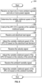
- FIG. 8 is a process flow diagram illustrating an exemplary method 200 of adjusting the variable rotational speed of the APU 22 when operating in the speed compensation mode. It is to be appreciated that blocks 208, 210, 212, 214, 216, and 218 of method 200 are optional, and may be omitted in some examples. Referring generally to FIGS. 1 , 2 , 4 , and 8 , the method 200 begins at block 202. In block 202, the control module 28 receives as input one or more ambient signals indicative of the air density value and one or more power signals indicative of the specific amount of power generated by the APU 22.
- the ambient signal is either a measured value (i.e., measured by an aneroid barometer) or a calculated value (i.e., based on altitude and temperature).
- the measured air density value is compared with the calculated air density value for redundancy. The method 200 may then proceed to block 204.
- control module 28 determines the variable rotational speed of the APU based on the air density value.
- the speed compensation curve 88 shown in FIG. 4 may be used to determine the variable rotational speed of the APU based on the air density value.
- the method 200 may then proceed to block 206.
- the control module 28 instructs the APU 22 to operate at the variable rotational speed, where the APU 22 continues to generate the specific amount of power when operating at the variable rotational speed.
- the method 200 may then terminate, and then then the APU 22 may operate in the ground maintenance mode.
- the control module 28 also performs speed compensation based on the electrical load demand on the generators 24, the aircraft velocity, the humidity, or any combination of load, aircraft velocity, or humidity. It is to be appreciated that while FIG. 8 includes adjusting the variable rotational speed of the APU 22 in a specific sequence, no specific order is required. Therefore, in an example, the method 200 may then proceed to block 208.
- control module 28 receives the electrical load signal 76, which is indicative of the electrical load demand by the one or more generators 24. The method 200 may then proceed to block 210.
- control module 28 adjusts the variable rotational speed of the APU 22 based on the electrical load demand of the one or more generators 24, which is described above and shown in FIG. 5 .
- the method 200 may then proceed to block 212.
- control module 28 receives the velocity signal, which indicates the velocity of the aircraft 20 compared to the speed of sound in air. The method 200 may then proceed to block 214.
- control module 28 adjusts the variable rotational speed of the APU 22 based on the velocity of the aircraft 20, which is described above and shown in FIG. 6 .
- the method 200 may then proceed to block 216.
- control module 28 receives the ambient humidity signal, which indicates the ambient humidity. The method 200 may then proceed to block 218.
- control module 28 adjusts the variable rotational speed of the APU 22 based on the ambient humidity, which is described above.
- the method 200 may then terminate or return to block 202.
- variable rotational speed of the APU 22 is first compensated for the air density value. Then, the variable rotational speed is adjusted based on other conditions such as the velocity of the aircraft 20 and the ambient humidity. Then, the variable rotational speed of the APU 22 is adjusted based on the electrical load demand on the generators 24. This is because ambient conditions such as the air density value, the velocity of the aircraft 20, and humidity do not typically vary or change in value suddenly by a significant amount.
- variable rotational speed of the APU 22 (and the associated power capability) is able to accommodate a sudden change in load more easily when compared to fixed-speed APUs. If the control module 28 predicts electrical load based on the flight plan, then the control module 28 determines the variable rotational speed of the APU 22 based on the predicted electrical load.
- the control module 28 first compensates for the air density value by instructing the APU 22 to operate at a first variable rotational speed. Then, after instructing APU 22 to operate at the first variable rotational speed, the control module 28 adjusts the first variable rotational speed of the APU 22 based on one or more ambient conditions of the aircraft 20. Specifically, the ambient conditions of the aircraft 20 include, but are not limited to, the velocity of the aircraft 20, which is compared to the speed of sound in air, and the ambient humidity. After compensating for the ambient conditions of the aircraft 20, the control module 28 compensates for the electrical load demand on the generators 24 by instructing the APU 22 to operate at a second variable rotational speed.
- control module 28 determines the second variable rotational speed of the APU 22 only after adjusting the first variable rotational speed of the APU 22 based on the ambient conditions of the aircraft 20.
- the second variable rotational speed is based on the air density value, the ambient conditions of the aircraft, and the electrical load demand on the generators 24.
- FIG. 9 an exemplary process flow diagram illustrating an exemplary method 300 for adjusting the rotational speed for an APU 22 in an electrically propelled aircraft is shown.
- the method 300 may begin at block 302.
- the control module 28 receives as input one or more ambient signals indicative of the air density value and one or more power signals indicative of the specific amount of power generated by the APU 22.
- the method 300 may then proceed to block 304.
- control module 28 determines the first variable rotational speed of the APU based on the air density value. The method 300 may then proceed to block 306.
- control module 28 instructs the APU 22 to operate at the first rotational rotational speed, where the APU 22 continues to generate the specific amount of power when operating at the variable rotational speed.
- the method 300 may then proceed to decision block 308.
- decision block 308 the method proceeds to block 310 if the variable rotational speed of the APU 22 is compensated for additional ambient conditions. Otherwise, the method 300 proceeds to block 320 to compensate for the electrical load demand of the generators 24.
- control module 28 receives the velocity signal, which indicates the velocity of the aircraft 20 compared to the speed of sound in air. The method 300 may then proceed to block 312.
- control module 28 adjusts the first variable rotational speed of the APU 22 based on the velocity of the aircraft 20, which is described above and shown in FIG. 6 .
- the method 300 may then proceed to block 314.
- control module 28 receives the ambient humidity signal, which indicates the ambient humidity.
- the method 300 may then proceed to block 316.
- control module 28 adjusts the first variable rotational speed of the APU 22 based on the ambient humidity, which is described above.
- the method 300 may then proceed to block 318.
- control module 28 receives the electrical load signal 76, which is indicative of the electrical load demand by the one or more generators 24. The method 300 may then proceed to block 320.
- the control module 28 determines a second variable rotational speed of the APU 22 based on the electrical load demand by the one or more generators 24. In other words, the control module 28 first adjusts the variable rotational speed of the APU 22 for ambient conditions (e.g., air density, humidity, velocity of the aircraft 20), and then adjusts the variable rotational speed of the APU 22 for electrical load demand. The method 300 may then proceed to block 322.
- ambient conditions e.g., air density, humidity, velocity of the aircraft 20
- the method 300 may then proceed to block 322.
- control module 28 instructs the APU 22 to operate at the second variable rotational speed.
- the method 300 may then return back to block 302.
- technical effects and benefits of the disclosed APU control system include a smaller, lightweight gas turbine that requires less fuel when compared to fixed-speed APUs.
- the disclosed APU compensates for ambient conditions that adversely affect the power output. Therefore, a smaller sized gas turbine may be used to perform the same function as a heavier fixed-speed gas turbine.
- the disclosed APU control system also provides rotational speed compensation based on the electrical load demand, which in turn improves the efficiency of the APU.
- the APU control system 18 is implemented on one or more computer devices or systems, such as exemplary computer system 1030 (e.g. as a computer-implemented method).
- the computer system 1030 includes a processor 1032, a memory 1034, a mass storage memory device 1036, an input/output (I/O) interface 1038, and a Human Machine Interface (HMI) 1040.
- the computer system 1030 is operatively coupled to one or more external resources 1042 via the network 1026 or I/O interface 1038.
- External resources may include, but are not limited to, servers, databases, mass storage devices, peripheral devices, cloud-based network services, or any other suitable computer resource that may be used by the computer system 1030.
- the processor 1032 includes one or more devices selected from microprocessors, microcontrollers, digital signal processors, microcomputers, central processing units, field programmable gate arrays, programmable logic devices, state machines, logic circuits, analog circuits, digital circuits, or any other devices that manipulate signals (analog or digital) based on operational instructions that are stored in the memory 1034.
- Memory 1034 includes a single memory device or a plurality of memory devices including, but not limited to, read-only memory (ROM), random access memory (RAM), volatile memory, non-volatile memory, static random-access memory (SRAM), dynamic random-access memory (DRAM), flash memory, cache memory, or any other device capable of storing information.
- the mass storage memory device 136 includes data storage devices such as a hard drive, optical drive, tape drive, volatile or non-volatile solid-state device, or any other device capable of storing information.
- the processor 1032 operates under the control of an operating system 1046 that resides in memory 1034.
- the operating system 1046 manages computer resources so that computer program code embodied as one or more computer software applications, such as an application 1048 residing in memory 1034, may have instructions executed by the processor 1032 (e.g. as a computer-implemented method).
- the processor 1032 may execute the application 1048 directly, in which case the operating system 1046 may be omitted.
- One or more data structures 1049 also reside in memory 1034, and may be used by the processor 1032, operating system 1046, or application 1048 to store or manipulate data.
- the I/O interface 1038 provides a machine interface that operatively couples the processor 1032 to other devices and systems, such as the network 1026 or external resource 1042.
- the application 1048 thereby works cooperatively with the network 1026 or external resource 1042 by communicating via the I/O interface 1038 to provide the various features, functions, applications, processes, or modules comprising examples of the disclosure.
- the application 1048 also includes program code that is executed by one or more external resources 1042, or otherwise rely on functions or signals provided by other system or network components external to the computer system 1030.
- examples of the disclosure may include applications that are located externally to the computer system 1030, distributed among multiple computers or other external resources 1042, or provided by computing resources (hardware and software) that are provided as a service over the network 1026, such as a cloud computing service.
- the HMI 1040 is operatively coupled to the processor 1032 of computer system 1030 in a known manner to allow a user to interact directly with the computer system 1030.
- the HMI 1040 may include video or alphanumeric displays, a touch screen, a speaker, and any other suitable audio and visual indicators capable of providing data to the user.
- the HMI 1040 also includes input devices and controls such as an alphanumeric keyboard, a pointing device, keypads, pushbuttons, control knobs, microphones, etc., capable of accepting commands or input from the user and transmitting the entered input to the processor 1032.
- a database 1044 may reside on the mass storage memory device 1036 and may be used to collect and organize data used by the various systems and modules described herein.
- the database 1044 may include data and supporting data structures that store and organize the data.
- the database 1044 may be arranged with any database organization or structure including, but not limited to, a relational database, a hierarchical database, a network database, or combinations thereof.
- a database management system in the form of a computer software application executing as instructions on the processor 1032 e.g. a computer-implemented method
Landscapes
- Engineering & Computer Science (AREA)
- Aviation & Aerospace Engineering (AREA)
- Chemical & Material Sciences (AREA)
- Combustion & Propulsion (AREA)
- Mechanical Engineering (AREA)
- General Engineering & Computer Science (AREA)
- Power Engineering (AREA)
- Control Of Eletrric Generators (AREA)
- Control Of Turbines (AREA)
- Supply And Distribution Of Alternating Current (AREA)
Claims (15)
- Steuersystem (18) eines Hilfstriebwerks (APU, Auxiliary Power Unit) für ein Flugzeug (20), wobei das APU-Steuersystem ein APU (22) enthält, das so konfiguriert ist, dass es antriebsmäßig mit einem oder mehreren Generatoren (24) gekoppelt werden kann, wobei das APU-Steuersystem Folgendes umfasst:einen oder mehrere Prozessoren (1032); undeinen Speicher (1034), der mit dem einen oder den mehreren Prozessoren gekoppelt ist, wobei der Speicher Daten speichert, die eine Datenbank (1044) und einen Programmcode umfassen, der, wenn er von dem einen oder den mehreren Prozessoren ausgeführt wird, das APU-Steuersystem zu Folgendem veranlasst:Erhalten eines oder mehrerer Umgebungssignale, die einen Luftdichtewert angeben, und eines oder mehrerer Leistungssignale, die eine bestimmte Menge an Leistung angeben, die von dem APU erzeugt wird;Bestimmen einer ersten variablen Drehzahl des APU basierend auf dem Luftdichtewert;Anweisen des APU, mit der ersten variablen Drehzahl zu arbeiten, wobei das APU weiter die bestimmte Leistungsmenge erzeugt, wenn es mit der ersten variablen Drehzahl arbeitet;nach dem Anweisen des APU, mit der ersten variablen Drehzahl zu arbeiten, Erhalten eines elektrischen Lastsignals (76), wobei das elektrische Lastsignal eine elektrische Lastanforderung des einen oder der mehreren Generatoren anzeigt;Bestimmen einer zweiten variablen Drehzahl des APU basierend auf der elektrischen Lastanforderung des einen oder der mehreren Generatoren; undAnweisen des APU, mit der zweiten variablen Drehzahl zu arbeiten.
- APU-Steuersystem (18) nach Anspruch 1, wobei der eine oder die mehreren Prozessoren (1032) Anweisungen ausführen, um das APU-Steuersystem (18) zu Folgendem zu veranlassen:Erhalten eines Temperatursignals und eines Höhensignals;Bestimmen des Luftdichtewerts basierend auf dem Temperatursignal und dem Höhensignal;Bestimmen, dass die elektrische Lastanforderung des einen oder der mehreren Generatoren (24) entweder zunimmt oder abnimmt;als Reaktion auf das Bestimmen, dass die elektrische Lastanforderung des einen oder der mehreren Generatoren zunimmt, Erhöhen der zweiten variablen Drehzahl des APU (22) basierend auf einer proportionalen Beziehung zwischen der elektrischen Lastanforderung und einer variablen Drehzahl des APU; undals Reaktion auf das Bestimmen, dass die elektrische Lastanforderung des einen oder der mehreren Generatoren abnimmt, Verringern der zweiten variablen Drehzahl des APU.
- APU-Steuersystem (18) nach einem der vorhergehenden Ansprüche, wobei der eine oder die mehreren Prozessoren (1032) Anweisungen ausführen, um das APU-Steuersystem (18) zu Folgendem zu veranlassen:nach dem Anweisen des APU (22), mit der ersten variablen Drehzahl zu arbeiten, Einstellen der ersten variablen Drehzahl des APU basierend auf einer oder mehreren Umgebungsbedingungen;nach dem Einstellen der ersten variablen Drehzahl des APU basierend auf der einen oder den mehreren Umgebungsbedingungen, Bestimmen der zweiten variablen Drehzahl des APU, wobei die zweite variable Drehzahl des APU auf dem Luftdichtewert, der einen oder mehreren Umgebungsbedingungen und der elektrischen Lastanforderung des einen oder der mehreren Generatoren (24) basiert.
- APU-Steuersystem (18) nach einem der vorhergehenden Ansprüche, wobei der eine oder die mehreren Prozessoren (1032) Anweisungen ausführen, um das APU-Steuersystem (18) zu Folgendem zu veranlassen:
dynamisches Einstellen der ersten variablen Drehzahl des APU (22) bei einem gegebenen Luftdichtewert proportional zu einer Größe der elektrischen Lastanforderung, wobei die erste variable Drehzahl des APU zwischen einer minimalen Drehzahl (134) und einer maximalen Drehzahl (132) einstellbar ist. - APU-Steuersystem (18) nach einem der vorhergehenden Ansprüche, wobei der Speicher (1034) einen Flugplan des Flugzeugs (20) speichert und wobei der eine oder die mehreren Prozessoren (1032) Anweisungen ausführen, um das APU-Steuersystem (18) zu Folgendem zu veranlassen:Berechnen einer vorhergesagten elektrischen Last basierend auf dem Flugplan, wobei die vorhergesagte elektrische Last auf einer Geschwindigkeitsänderung einer Vielzahl von Elektromotoren basiert, und wobei die Geschwindigkeitsänderung der Vielzahl von Elektromotoren die Fluglage oder Winkelgeschwindigkeit des Flugzeugs steuert; undBestimmen der zweiten variablen Drehzahl des APU (22) basierend auf der vorhergesagten elektrischen Last.
- APU-Steuersystem (18) nach einem der vorhergehenden Ansprüche, wobei der eine oder die mehreren Prozessoren (1032) Anweisungen ausführen, um das APU-Steuersystem (18) zu Folgendem zu veranlassen:nach dem Anweisen des APU (22), mit der ersten variablen Drehzahl zu arbeiten, Erhalten eines Geschwindigkeitssignals, das eine Geschwindigkeit des Flugzeugs (20) im Vergleich zu einer Schallgeschwindigkeit in Luft bei einem gegebenen Luftdichtewert angibt;Bestimmen, dass die Geschwindigkeit des Flugzeugs kleiner als ein Maximalwert ist; undals Reaktion auf das Bestimmen, dass die Geschwindigkeit des Flugzeugs kleiner als der Maximalwert ist, Einstellen der ersten variablen Drehzahl des APU basierend auf einer linearen umgekehrt proportionalen Beziehung zwischen der Geschwindigkeit des Flugzeugs und der erste variablen Drehzahl des APU.
- APU-Steuersystem (18) nach einem der Ansprüche 1 bis 5, wobei der eine oder die mehreren Prozessoren (1032) Anweisungen ausführen, um das APU-Steuersystem (18) zu Folgendem zu veranlassen:nach dem Anweisen des APU (22), mit der ersten variablen Drehzahl zu arbeiten, Erhalten eines Geschwindigkeitssignals, das eine Geschwindigkeit des Flugzeugs im Vergleich zu einer Schallgeschwindigkeit in Luft bei einem gegebenen Luftdichtewert angibt;Bestimmen, dass die Geschwindigkeit des Flugzeugs (20) bei einem Maximalwert ist; undals Reaktion auf das Bestimmen, dass die Geschwindigkeit des Flugzeugs bei dem Maximalwert ist, Bestimmen, dass die erste variable Drehzahl des APU statisch bleibt.
- APU-Steuersystem (18) nach einem der Ansprüche 1 bis 7, wobei der eine oder die mehreren Prozessoren (1032) Anweisungen ausführen, um das APU-Steuersystem (18) zu Folgendem zu veranlassen:nach dem Anweisen des APU (22), mit der ersten variablen Drehzahl zu arbeiten, Erhalten eines Umgebungsfeuchtigkeitssignals, das eine absolute Luftfeuchte bei einer gegebenen Luftdichte angibt;Bestimmen der absoluten Luftfeuchtigkeit basierend auf dem Umgebungsfeuchtigkeitssignal; undEinstellen der ersten variablen Drehzahl des APU basierend auf der absoluten Luftfeuchtigkeit, wobei eine umgekehrt proportionale Beziehung zwischen der absoluten Luftfeuchtigkeit und einer Leistungsabgabe des APU besteht.
- APU-Steuersystem (18) nach einem der Ansprüche 1 bis 8, wobei der eine oder die mehreren Prozessoren (1032) Anweisungen ausführen, um das APU-Steuersystem (18) zu Folgendem zu veranlassen:Bestimmen, dass sich das Flugzeug (20) am Boden befindet; undals Reaktion auf das Bestimmen, dass sich das Flugzeug am Boden befindet, Anweisen des APU (22), mit einer Bandbreitendrehzahl zu arbeiten, wobei ein Bereich der Bandbreitendrehzahl mit einer elektrischen Stromversorgung für Flugzeug-Bodenunterstützungsausrüstung kompatibel ist.
- APU-Steuersystem (18) nach einem der Ansprüche 1 bis 8, wobei der eine oder die mehreren Prozessoren (1032) Anweisungen ausführen, um das APU-Steuersystem (18) zu Folgendem zu veranlassen:Bestimmen, dass sich das Flugzeug (20) am Boden befindet; undals Reaktion auf das Bestimmen, dass sich das Flugzeug am Boden befindet, Anweisen des APU (22), mit einer benutzerdefinierten Drehzahl zu arbeiten, wobei es sich bei der benutzerdefinierten Drehzahl um eine diskrete Drehzahl oder einen Bereich von Drehzahlen handelt, der von einer Person bestimmt wird.
- Verfahren zum Einstellen einer variablen Drehzahl eines APU (22) in einem Flugzeug (20), wobei das Verfahren Folgendes umfasst:Empfangen eines oder mehrerer Umgebungssignale an einem Computer (1030), die einen Luftdichtewert angeben, und eines oder mehrerer Leistungssignale, die eine bestimmte Menge an Leistung angeben, die von dem APU (22) erzeugt wird;Bestimmen einer ersten variablen Drehzahl des APU basierend auf dem Luftdichtewert durch den Computer;Anweisen des APU, mit der ersten variablen Drehzahl zu arbeiten, wobei das APU ferner die bestimmte Leistungsmenge erzeugt, wenn es mit der variablen Drehzahl arbeitet;nach dem Anweisen des APU, mit der ersten variablen Drehzahl zu arbeiten, Empfangen eines elektrischen Lastsignals (76), wobei das elektrische Lastsignal eine elektrische Lastanforderung des einen oder den mehreren Generatoren (24), die antriebsmäßig mit dem APU gekoppelt sind, anzeigt; Bestimmen einer zweiten variablen Drehzahl des APU basierend auf der elektrischen Lastanforderung des einen oder der mehreren Generatoren durch den Computer; undAnweisen des APU, mit der zweiten variablen Drehzahl zu arbeiten.
- Verfahren nach Anspruch 11, das ferner Folgendes umfasst:Empfangen eines Temperatursignals und eines Höhensignals; undBestimmen des Luftdichtewerts basierend auf dem Temperatursignal und dem Höhensignal.
- Verfahren nach einem der Ansprüche 11 oder 12, das ferner Folgendes umfasst:Bestimmen, dass die elektrische Lastanforderung an dem einen oder den mehreren Generatoren (24) entweder zunimmt oder abnimmt;als Reaktion auf das Bestimmen, dass die elektrische Lastanforderung des einen oder der mehreren Generatoren zunimmt, Erhöhen der zweiten variablen Drehzahl des APU (22) basierend auf einer proportionalen Beziehung zwischen der elektrischen Lastanforderung und der variablen Drehzahl des APU; undals Reaktion auf das Bestimmen, dass die elektrische Lastanforderung an dem einen oder den mehreren Generatoren abnimmt, Verringern der zweiten variablen Drehzahl des APU basierend auf einer proportionalen Beziehung zwischen der elektrischen Lastanforderung Strombedarfs und der variablen Drehzahl des APU.
- Verfahren nach einem der Ansprüche 11 bis 13, das ferner Folgendes umfasst:nach dem Anweisen des APU (22), mit der ersten variablen Drehzahl zu arbeiten, Einstellen der ersten variablen Drehzahl des APU basierend auf der einen oder den mehreren Umgebungsbedingungen;nach dem Einstellen der ersten variablen Drehzahl des APU basierend auf der einen oder den mehreren Umgebungsbedingungen, Bestimmen der zweiten variablen Drehzahl des APU, wobei die zweite variable Drehzahl der APU auf dem Luftdichtewert, der einen oder mehreren Umgebungsbedingungen und der elektrischen Lastanforderung des einen oder der mehreren Generatoren (24) basiert.
- Verfahren nach einem der Ansprüche 11 bis 14, das ferner Folgendes umfasst:Berechnen einer vorhergesagten elektrischen Last basierend auf einem in einem Speicher des Computers gespeicherten Flugplan, wobei die vorhergesagte elektrische Last auf einer Geschwindigkeitsänderung einer Vielzahl von Elektromotoren basiert, wobei die Drehzahländerung der Vielzahl von Elektromotoren eine Fluglage oder Winkelgeschwindigkeit des Flugzeugs (20) steuert; undBestimmen der zweiten variablen Drehzahl des APU (22) basierend auf der vorhergesagten elektrischen Last.
Applications Claiming Priority (1)
| Application Number | Priority Date | Filing Date | Title |
|---|---|---|---|
| US16/260,307 US10974844B2 (en) | 2019-01-29 | 2019-01-29 | Aircraft auxiliary power unit (APU) control system having speed compensation |
Publications (2)
| Publication Number | Publication Date |
|---|---|
| EP3689752A1 EP3689752A1 (de) | 2020-08-05 |
| EP3689752B1 true EP3689752B1 (de) | 2023-10-04 |
Family
ID=69374199
Family Applications (1)
| Application Number | Title | Priority Date | Filing Date |
|---|---|---|---|
| EP20154043.2A Active EP3689752B1 (de) | 2019-01-29 | 2020-01-28 | Flugzeughilfstriebwerk (apu) mit geschwindigkeitskompensation |
Country Status (6)
| Country | Link |
|---|---|
| US (1) | US10974844B2 (de) |
| EP (1) | EP3689752B1 (de) |
| JP (1) | JP7356917B2 (de) |
| KR (1) | KR102692770B1 (de) |
| CN (1) | CN111483601B (de) |
| CA (1) | CA3068669C (de) |
Families Citing this family (8)
| Publication number | Priority date | Publication date | Assignee | Title |
|---|---|---|---|---|
| US11034463B2 (en) * | 2019-03-26 | 2021-06-15 | The Boeing Company | Aircraft auxiliary power unit (APU) control system having variably sized air inlet |
| US11225910B2 (en) * | 2019-11-05 | 2022-01-18 | General Electric Company | Load anticipator system for a generator system |
| US12110121B2 (en) * | 2020-03-05 | 2024-10-08 | Yaborã Indústria Aeronáutica S.A. | Systems and methods for defining APU steady state speed according to the aircraft operational conditions |
| CN114109616B (zh) * | 2021-11-05 | 2023-09-19 | 江西洪都航空工业集团有限责任公司 | 一种发动机高空起动供油调节方法、装置和系统 |
| CN114400928B (zh) * | 2022-01-06 | 2024-05-03 | 广东和汇智能装备有限公司 | 云控智能无刷电机驱动系统 |
| US11808211B2 (en) | 2022-04-08 | 2023-11-07 | Hamilton Sundstrand Corporation | Multi-speed transmission to control variable APU speed and constant generator output frequency |
| US11697998B1 (en) | 2022-04-08 | 2023-07-11 | Hamilton Sundstrand Corporation | Constant speed drive to control variable APU speed and constant generator output frequency |
| KR102693130B1 (ko) | 2022-08-29 | 2024-08-07 | 김상곤 | 보조 동력 장치에 사용되는 체크밸브 |
Family Cites Families (29)
| Publication number | Priority date | Publication date | Assignee | Title |
|---|---|---|---|---|
| US5675188A (en) | 1993-07-23 | 1997-10-07 | Hitachi, Ltd. | Adjustable speed gas turbine power generation apparatus and its operation method independent of ambient temperature |
| US6487490B1 (en) * | 1999-05-26 | 2002-11-26 | General Electric Company | Speed modification system for gas turbine engine to allow trimming of excess |
| US6735951B2 (en) | 2002-01-04 | 2004-05-18 | Hamilton Sundstrand Corporation | Turbocharged auxiliary power unit with controlled high speed spool |
| US6968674B2 (en) * | 2003-01-28 | 2005-11-29 | General Electric Company | Methods and apparatus for operating gas turbine engines |
| US7549291B2 (en) * | 2003-01-28 | 2009-06-23 | General Electric Company | Methods and apparatus for operating gas turbine engines |
| US6777822B1 (en) | 2003-04-01 | 2004-08-17 | Hamilton Sundstrand Corporation | Control system for an auxiliary power unit |
| US7367193B1 (en) | 2003-07-23 | 2008-05-06 | Hamilton Sundstrand Corporation | Auxiliary power unit control method and system |
| RU2235042C1 (ru) * | 2003-11-12 | 2004-08-27 | Оао "Миэа" | Способ управления самолетом |
| US8209101B2 (en) | 2006-08-29 | 2012-06-26 | The Boeing Company | Method and system for adaptive power management |
| US8165790B2 (en) | 2009-08-26 | 2012-04-24 | The Boeing Company | Dynamic weather selection |
| US20130204544A1 (en) | 2012-02-03 | 2013-08-08 | Gulfstream Aerospace Corporation | Methods and systems for determining airspeed of an aircraft |
| US8813503B2 (en) * | 2012-06-14 | 2014-08-26 | General Electric Company | Gas turbine control systems and methods |
| FR3016706B1 (fr) | 2014-01-23 | 2016-02-26 | Airbus Operations Sas | Procede et dispositif pour optimiser l'atterrissage d'un aeronef sur une piste. |
| FR3019215B1 (fr) * | 2014-03-27 | 2019-05-31 | Safran Helicopter Engines | Dispositif d'assistance pour une turbomachine a turbine libre d'un aeronef comprenant au moins deux turbomachines a turbine libre |
| US20150283908A1 (en) | 2014-04-02 | 2015-10-08 | Hamilton Sundstrand Corporation | Systems utilizing a controllable voltage ac generator system |
| US9550577B1 (en) * | 2014-06-26 | 2017-01-24 | Amazon Technologies, Inc. | Electricity generation in automated aerial vehicles |
| US9409653B2 (en) | 2014-09-17 | 2016-08-09 | The Boeing Company | Auxilliary power and thrust unit drive system |
| FR3028498B1 (fr) | 2014-11-14 | 2018-06-01 | Airbus Operations | Dispositif pour la commande d'un regime de poussee d'au moins un moteur d'aeronef. |
| US9845806B2 (en) | 2015-06-04 | 2017-12-19 | United Technologies Corporation | Engine speed optimization as a method to reduce APU fuel consumption |
| US10590842B2 (en) * | 2015-06-25 | 2020-03-17 | Pratt & Whitney Canada Corp. | Compound engine assembly with bleed air |
| US10710738B2 (en) * | 2015-06-25 | 2020-07-14 | Pratt & Whitney Canada Corp. | Auxiliary power unit with intercooler |
| US9771165B2 (en) * | 2015-06-25 | 2017-09-26 | Pratt & Whitney Canada Corp. | Compound engine assembly with direct drive of generator |
| US10696417B2 (en) * | 2015-06-25 | 2020-06-30 | Pratt & Whitney Canada Corp. | Auxiliary power unit with excess air recovery |
| US10240521B2 (en) * | 2015-08-07 | 2019-03-26 | Pratt & Whitney Canada Corp. | Auxiliary power unit with variable speed ratio |
| US10253687B2 (en) * | 2015-08-07 | 2019-04-09 | Pratt & Whitney Canada Corp. | Auxiliary power unit with electrically driven compressor |
| EP3179077B1 (de) | 2015-12-11 | 2018-09-12 | Airbus Operations, S.L. | Kraftstoffregelsystem für gasturbinenmotor eines flugzeugs |
| FR3060653B1 (fr) | 2016-12-15 | 2019-05-24 | Safran Power Units | Unite de generation de puissance electrique non propulsive |
| US10232951B2 (en) * | 2017-02-20 | 2019-03-19 | Pratt & Whitney Canada Corp. | System and method for selecting an opening angle of an auxiliary power unit inlet door |
| US10435168B2 (en) * | 2017-02-20 | 2019-10-08 | Pratt & Whitney Canada Corp. | System and method for controlling a position of an auxiliary power unit inlet door |
-
2019
- 2019-01-29 US US16/260,307 patent/US10974844B2/en active Active
-
2020
- 2020-01-17 CA CA3068669A patent/CA3068669C/en active Active
- 2020-01-20 JP JP2020006521A patent/JP7356917B2/ja active Active
- 2020-01-22 KR KR1020200008262A patent/KR102692770B1/ko active Active
- 2020-01-23 CN CN202010076549.4A patent/CN111483601B/zh active Active
- 2020-01-28 EP EP20154043.2A patent/EP3689752B1/de active Active
Also Published As
| Publication number | Publication date |
|---|---|
| CA3068669A1 (en) | 2020-07-29 |
| EP3689752A1 (de) | 2020-08-05 |
| CN111483601A (zh) | 2020-08-04 |
| JP7356917B2 (ja) | 2023-10-05 |
| JP2020125104A (ja) | 2020-08-20 |
| US10974844B2 (en) | 2021-04-13 |
| CA3068669C (en) | 2023-09-26 |
| KR102692770B1 (ko) | 2024-08-06 |
| KR20200094666A (ko) | 2020-08-07 |
| CN111483601B (zh) | 2025-01-03 |
| US20200239156A1 (en) | 2020-07-30 |
Similar Documents
| Publication | Publication Date | Title |
|---|---|---|
| EP3690216B1 (de) | Flugzeughilfstriebwerk mit geschwindigkeitskompensation | |
| EP3689752B1 (de) | Flugzeughilfstriebwerk (apu) mit geschwindigkeitskompensation | |
| US11286865B2 (en) | Gas turbine engine with variable pitch fan and variable pitch compressor geometry | |
| US11299286B2 (en) | System and method for operating a multi-engine aircraft | |
| CN112081664B (zh) | 改善气体涡轮的减速 | |
| RU2598476C2 (ru) | Способ контроля генерирования электричества, применяемого для газовой турбины летательного аппарата и устройство для применения такого способа | |
| US10941711B2 (en) | Device for automatically regulating aircraft power plant gas generator and free turbine speeds as a function of heating, electricity generation, noise emission, and fuel consumption | |
| US20200010205A1 (en) | Aircraft electrically-assisted propulsion control system | |
| US4370560A (en) | Compressor load control for an auxiliary power unit | |
| US7367193B1 (en) | Auxiliary power unit control method and system | |
| US20180118364A1 (en) | System and method for augmenting a primary powerplant | |
| US11034463B2 (en) | Aircraft auxiliary power unit (APU) control system having variably sized air inlet | |
| JP2013505172A (ja) | 航空機の電力管理装置 | |
| CN111720353B (zh) | 用于控制送往气动系统的压缩空气的方法 | |
| Lutambo et al. | Aircraft turbine engine control systems development: Historical Perspective | |
| US11535386B2 (en) | System and method for operating a multi-engine rotorcraft for ice accretion shedding | |
| US20240067347A1 (en) | Aircrafts, systems, and methods for providing constant torque on takeoff | |
| GB2575743A (en) | Aircraft electrically-assisted propulsion control system | |
| US12448112B1 (en) | Power generation and transfer using variable-pitch propeller |
Legal Events
| Date | Code | Title | Description |
|---|---|---|---|
| PUAI | Public reference made under article 153(3) epc to a published international application that has entered the european phase |
Free format text: ORIGINAL CODE: 0009012 |
|
| STAA | Information on the status of an ep patent application or granted ep patent |
Free format text: STATUS: THE APPLICATION HAS BEEN PUBLISHED |
|
| AK | Designated contracting states |
Kind code of ref document: A1 Designated state(s): AL AT BE BG CH CY CZ DE DK EE ES FI FR GB GR HR HU IE IS IT LI LT LU LV MC MK MT NL NO PL PT RO RS SE SI SK SM TR |
|
| AX | Request for extension of the european patent |
Extension state: BA ME |
|
| STAA | Information on the status of an ep patent application or granted ep patent |
Free format text: STATUS: REQUEST FOR EXAMINATION WAS MADE |
|
| 17P | Request for examination filed |
Effective date: 20210118 |
|
| RBV | Designated contracting states (corrected) |
Designated state(s): AL AT BE BG CH CY CZ DE DK EE ES FI FR GB GR HR HU IE IS IT LI LT LU LV MC MK MT NL NO PL PT RO RS SE SI SK SM TR |
|
| GRAP | Despatch of communication of intention to grant a patent |
Free format text: ORIGINAL CODE: EPIDOSNIGR1 |
|
| STAA | Information on the status of an ep patent application or granted ep patent |
Free format text: STATUS: GRANT OF PATENT IS INTENDED |
|
| RIC1 | Information provided on ipc code assigned before grant |
Ipc: B64D 27/24 20060101ALN20220215BHEP Ipc: F02C 9/44 20060101ALI20220215BHEP Ipc: F01D 15/10 20060101ALI20220215BHEP Ipc: F02C 9/28 20060101ALI20220215BHEP Ipc: B64D 31/06 20060101ALI20220215BHEP Ipc: B64D 41/00 20060101AFI20220215BHEP |
|
| INTG | Intention to grant announced |
Effective date: 20220316 |
|
| GRAJ | Information related to disapproval of communication of intention to grant by the applicant or resumption of examination proceedings by the epo deleted |
Free format text: ORIGINAL CODE: EPIDOSDIGR1 |
|
| STAA | Information on the status of an ep patent application or granted ep patent |
Free format text: STATUS: REQUEST FOR EXAMINATION WAS MADE |
|
| STAA | Information on the status of an ep patent application or granted ep patent |
Free format text: STATUS: EXAMINATION IS IN PROGRESS |
|
| INTC | Intention to grant announced (deleted) | ||
| 17Q | First examination report despatched |
Effective date: 20220714 |
|
| RAP3 | Party data changed (applicant data changed or rights of an application transferred) |
Owner name: THE BOEING COMPANY |
|
| GRAP | Despatch of communication of intention to grant a patent |
Free format text: ORIGINAL CODE: EPIDOSNIGR1 |
|
| STAA | Information on the status of an ep patent application or granted ep patent |
Free format text: STATUS: GRANT OF PATENT IS INTENDED |
|
| RIC1 | Information provided on ipc code assigned before grant |
Ipc: B64D 27/24 20060101ALN20230629BHEP Ipc: F02C 9/44 20060101ALI20230629BHEP Ipc: F01D 15/10 20060101ALI20230629BHEP Ipc: F02C 9/28 20060101ALI20230629BHEP Ipc: B64D 31/06 20060101ALI20230629BHEP Ipc: B64D 41/00 20060101AFI20230629BHEP |
|
| INTG | Intention to grant announced |
Effective date: 20230714 |
|
| GRAS | Grant fee paid |
Free format text: ORIGINAL CODE: EPIDOSNIGR3 |
|
| GRAA | (expected) grant |
Free format text: ORIGINAL CODE: 0009210 |
|
| STAA | Information on the status of an ep patent application or granted ep patent |
Free format text: STATUS: THE PATENT HAS BEEN GRANTED |
|
| AK | Designated contracting states |
Kind code of ref document: B1 Designated state(s): AL AT BE BG CH CY CZ DE DK EE ES FI FR GB GR HR HU IE IS IT LI LT LU LV MC MK MT NL NO PL PT RO RS SE SI SK SM TR |
|
| REG | Reference to a national code |
Ref country code: GB Ref legal event code: FG4D |
|
| REG | Reference to a national code |
Ref country code: CH Ref legal event code: EP |
|
| REG | Reference to a national code |
Ref country code: IE Ref legal event code: FG4D |
|
| REG | Reference to a national code |
Ref country code: DE Ref legal event code: R096 Ref document number: 602020018458 Country of ref document: DE |
|
| P01 | Opt-out of the competence of the unified patent court (upc) registered |
Effective date: 20230921 |
|
| REG | Reference to a national code |
Ref country code: LT Ref legal event code: MG9D |
|
| REG | Reference to a national code |
Ref country code: NL Ref legal event code: MP Effective date: 20231004 |
|
| REG | Reference to a national code |
Ref country code: AT Ref legal event code: MK05 Ref document number: 1617542 Country of ref document: AT Kind code of ref document: T Effective date: 20231004 |
|
| PG25 | Lapsed in a contracting state [announced via postgrant information from national office to epo] |
Ref country code: NL Free format text: LAPSE BECAUSE OF FAILURE TO SUBMIT A TRANSLATION OF THE DESCRIPTION OR TO PAY THE FEE WITHIN THE PRESCRIBED TIME-LIMIT Effective date: 20231004 |
|
| PG25 | Lapsed in a contracting state [announced via postgrant information from national office to epo] |
Ref country code: GR Free format text: LAPSE BECAUSE OF FAILURE TO SUBMIT A TRANSLATION OF THE DESCRIPTION OR TO PAY THE FEE WITHIN THE PRESCRIBED TIME-LIMIT Effective date: 20240105 |
|
| PG25 | Lapsed in a contracting state [announced via postgrant information from national office to epo] |
Ref country code: IS Free format text: LAPSE BECAUSE OF FAILURE TO SUBMIT A TRANSLATION OF THE DESCRIPTION OR TO PAY THE FEE WITHIN THE PRESCRIBED TIME-LIMIT Effective date: 20240204 |
|
| PG25 | Lapsed in a contracting state [announced via postgrant information from national office to epo] |
Ref country code: LT Free format text: LAPSE BECAUSE OF FAILURE TO SUBMIT A TRANSLATION OF THE DESCRIPTION OR TO PAY THE FEE WITHIN THE PRESCRIBED TIME-LIMIT Effective date: 20231004 |
|
| PG25 | Lapsed in a contracting state [announced via postgrant information from national office to epo] |
Ref country code: AT Free format text: LAPSE BECAUSE OF FAILURE TO SUBMIT A TRANSLATION OF THE DESCRIPTION OR TO PAY THE FEE WITHIN THE PRESCRIBED TIME-LIMIT Effective date: 20231004 |
|
| PG25 | Lapsed in a contracting state [announced via postgrant information from national office to epo] |
Ref country code: ES Free format text: LAPSE BECAUSE OF FAILURE TO SUBMIT A TRANSLATION OF THE DESCRIPTION OR TO PAY THE FEE WITHIN THE PRESCRIBED TIME-LIMIT Effective date: 20231004 |
|
| PG25 | Lapsed in a contracting state [announced via postgrant information from national office to epo] |
Ref country code: LT Free format text: LAPSE BECAUSE OF FAILURE TO SUBMIT A TRANSLATION OF THE DESCRIPTION OR TO PAY THE FEE WITHIN THE PRESCRIBED TIME-LIMIT Effective date: 20231004 Ref country code: IS Free format text: LAPSE BECAUSE OF FAILURE TO SUBMIT A TRANSLATION OF THE DESCRIPTION OR TO PAY THE FEE WITHIN THE PRESCRIBED TIME-LIMIT Effective date: 20240204 Ref country code: GR Free format text: LAPSE BECAUSE OF FAILURE TO SUBMIT A TRANSLATION OF THE DESCRIPTION OR TO PAY THE FEE WITHIN THE PRESCRIBED TIME-LIMIT Effective date: 20240105 Ref country code: ES Free format text: LAPSE BECAUSE OF FAILURE TO SUBMIT A TRANSLATION OF THE DESCRIPTION OR TO PAY THE FEE WITHIN THE PRESCRIBED TIME-LIMIT Effective date: 20231004 Ref country code: BG Free format text: LAPSE BECAUSE OF FAILURE TO SUBMIT A TRANSLATION OF THE DESCRIPTION OR TO PAY THE FEE WITHIN THE PRESCRIBED TIME-LIMIT Effective date: 20240104 Ref country code: AT Free format text: LAPSE BECAUSE OF FAILURE TO SUBMIT A TRANSLATION OF THE DESCRIPTION OR TO PAY THE FEE WITHIN THE PRESCRIBED TIME-LIMIT Effective date: 20231004 Ref country code: PT Free format text: LAPSE BECAUSE OF FAILURE TO SUBMIT A TRANSLATION OF THE DESCRIPTION OR TO PAY THE FEE WITHIN THE PRESCRIBED TIME-LIMIT Effective date: 20240205 |
|
| PG25 | Lapsed in a contracting state [announced via postgrant information from national office to epo] |
Ref country code: SE Free format text: LAPSE BECAUSE OF FAILURE TO SUBMIT A TRANSLATION OF THE DESCRIPTION OR TO PAY THE FEE WITHIN THE PRESCRIBED TIME-LIMIT Effective date: 20231004 Ref country code: RS Free format text: LAPSE BECAUSE OF FAILURE TO SUBMIT A TRANSLATION OF THE DESCRIPTION OR TO PAY THE FEE WITHIN THE PRESCRIBED TIME-LIMIT Effective date: 20231004 Ref country code: PL Free format text: LAPSE BECAUSE OF FAILURE TO SUBMIT A TRANSLATION OF THE DESCRIPTION OR TO PAY THE FEE WITHIN THE PRESCRIBED TIME-LIMIT Effective date: 20231004 Ref country code: NO Free format text: LAPSE BECAUSE OF FAILURE TO SUBMIT A TRANSLATION OF THE DESCRIPTION OR TO PAY THE FEE WITHIN THE PRESCRIBED TIME-LIMIT Effective date: 20240104 Ref country code: LV Free format text: LAPSE BECAUSE OF FAILURE TO SUBMIT A TRANSLATION OF THE DESCRIPTION OR TO PAY THE FEE WITHIN THE PRESCRIBED TIME-LIMIT Effective date: 20231004 Ref country code: HR Free format text: LAPSE BECAUSE OF FAILURE TO SUBMIT A TRANSLATION OF THE DESCRIPTION OR TO PAY THE FEE WITHIN THE PRESCRIBED TIME-LIMIT Effective date: 20231004 |
|
| REG | Reference to a national code |
Ref country code: DE Ref legal event code: R097 Ref document number: 602020018458 Country of ref document: DE |
|
| PG25 | Lapsed in a contracting state [announced via postgrant information from national office to epo] |
Ref country code: DK Free format text: LAPSE BECAUSE OF FAILURE TO SUBMIT A TRANSLATION OF THE DESCRIPTION OR TO PAY THE FEE WITHIN THE PRESCRIBED TIME-LIMIT Effective date: 20231004 |
|
| PG25 | Lapsed in a contracting state [announced via postgrant information from national office to epo] |
Ref country code: CZ Free format text: LAPSE BECAUSE OF FAILURE TO SUBMIT A TRANSLATION OF THE DESCRIPTION OR TO PAY THE FEE WITHIN THE PRESCRIBED TIME-LIMIT Effective date: 20231004 |
|
| PG25 | Lapsed in a contracting state [announced via postgrant information from national office to epo] |
Ref country code: SK Free format text: LAPSE BECAUSE OF FAILURE TO SUBMIT A TRANSLATION OF THE DESCRIPTION OR TO PAY THE FEE WITHIN THE PRESCRIBED TIME-LIMIT Effective date: 20231004 |
|
| PG25 | Lapsed in a contracting state [announced via postgrant information from national office to epo] |
Ref country code: SM Free format text: LAPSE BECAUSE OF FAILURE TO SUBMIT A TRANSLATION OF THE DESCRIPTION OR TO PAY THE FEE WITHIN THE PRESCRIBED TIME-LIMIT Effective date: 20231004 Ref country code: SK Free format text: LAPSE BECAUSE OF FAILURE TO SUBMIT A TRANSLATION OF THE DESCRIPTION OR TO PAY THE FEE WITHIN THE PRESCRIBED TIME-LIMIT Effective date: 20231004 Ref country code: RO Free format text: LAPSE BECAUSE OF FAILURE TO SUBMIT A TRANSLATION OF THE DESCRIPTION OR TO PAY THE FEE WITHIN THE PRESCRIBED TIME-LIMIT Effective date: 20231004 Ref country code: IT Free format text: LAPSE BECAUSE OF FAILURE TO SUBMIT A TRANSLATION OF THE DESCRIPTION OR TO PAY THE FEE WITHIN THE PRESCRIBED TIME-LIMIT Effective date: 20231004 Ref country code: EE Free format text: LAPSE BECAUSE OF FAILURE TO SUBMIT A TRANSLATION OF THE DESCRIPTION OR TO PAY THE FEE WITHIN THE PRESCRIBED TIME-LIMIT Effective date: 20231004 Ref country code: DK Free format text: LAPSE BECAUSE OF FAILURE TO SUBMIT A TRANSLATION OF THE DESCRIPTION OR TO PAY THE FEE WITHIN THE PRESCRIBED TIME-LIMIT Effective date: 20231004 Ref country code: CZ Free format text: LAPSE BECAUSE OF FAILURE TO SUBMIT A TRANSLATION OF THE DESCRIPTION OR TO PAY THE FEE WITHIN THE PRESCRIBED TIME-LIMIT Effective date: 20231004 |
|
| PLBE | No opposition filed within time limit |
Free format text: ORIGINAL CODE: 0009261 |
|
| STAA | Information on the status of an ep patent application or granted ep patent |
Free format text: STATUS: NO OPPOSITION FILED WITHIN TIME LIMIT |
|
| PG25 | Lapsed in a contracting state [announced via postgrant information from national office to epo] |
Ref country code: MC Free format text: LAPSE BECAUSE OF FAILURE TO SUBMIT A TRANSLATION OF THE DESCRIPTION OR TO PAY THE FEE WITHIN THE PRESCRIBED TIME-LIMIT Effective date: 20231004 |
|
| PG25 | Lapsed in a contracting state [announced via postgrant information from national office to epo] |
Ref country code: MC Free format text: LAPSE BECAUSE OF FAILURE TO SUBMIT A TRANSLATION OF THE DESCRIPTION OR TO PAY THE FEE WITHIN THE PRESCRIBED TIME-LIMIT Effective date: 20231004 |
|
| REG | Reference to a national code |
Ref country code: CH Ref legal event code: PL |
|
| 26N | No opposition filed |
Effective date: 20240705 |
|
| PG25 | Lapsed in a contracting state [announced via postgrant information from national office to epo] |
Ref country code: LU Free format text: LAPSE BECAUSE OF NON-PAYMENT OF DUE FEES Effective date: 20240128 |
|
| PG25 | Lapsed in a contracting state [announced via postgrant information from national office to epo] |
Ref country code: LU Free format text: LAPSE BECAUSE OF NON-PAYMENT OF DUE FEES Effective date: 20240128 |
|
| PG25 | Lapsed in a contracting state [announced via postgrant information from national office to epo] |
Ref country code: BE Free format text: LAPSE BECAUSE OF NON-PAYMENT OF DUE FEES Effective date: 20240131 |
|
| PG25 | Lapsed in a contracting state [announced via postgrant information from national office to epo] |
Ref country code: CH Free format text: LAPSE BECAUSE OF NON-PAYMENT OF DUE FEES Effective date: 20240131 |
|
| PG25 | Lapsed in a contracting state [announced via postgrant information from national office to epo] |
Ref country code: SI Free format text: LAPSE BECAUSE OF FAILURE TO SUBMIT A TRANSLATION OF THE DESCRIPTION OR TO PAY THE FEE WITHIN THE PRESCRIBED TIME-LIMIT Effective date: 20231004 |
|
| PG25 | Lapsed in a contracting state [announced via postgrant information from national office to epo] |
Ref country code: SI Free format text: LAPSE BECAUSE OF FAILURE TO SUBMIT A TRANSLATION OF THE DESCRIPTION OR TO PAY THE FEE WITHIN THE PRESCRIBED TIME-LIMIT Effective date: 20231004 Ref country code: CH Free format text: LAPSE BECAUSE OF NON-PAYMENT OF DUE FEES Effective date: 20240131 Ref country code: BE Free format text: LAPSE BECAUSE OF NON-PAYMENT OF DUE FEES Effective date: 20240131 |
|
| REG | Reference to a national code |
Ref country code: BE Ref legal event code: MM Effective date: 20240131 |
|
| PG25 | Lapsed in a contracting state [announced via postgrant information from national office to epo] |
Ref country code: IE Free format text: LAPSE BECAUSE OF NON-PAYMENT OF DUE FEES Effective date: 20240128 |
|
| PG25 | Lapsed in a contracting state [announced via postgrant information from national office to epo] |
Ref country code: IE Free format text: LAPSE BECAUSE OF NON-PAYMENT OF DUE FEES Effective date: 20240128 |
|
| PG25 | Lapsed in a contracting state [announced via postgrant information from national office to epo] |
Ref country code: CY Free format text: LAPSE BECAUSE OF FAILURE TO SUBMIT A TRANSLATION OF THE DESCRIPTION OR TO PAY THE FEE WITHIN THE PRESCRIBED TIME-LIMIT; INVALID AB INITIO Effective date: 20200128 |
|
| PG25 | Lapsed in a contracting state [announced via postgrant information from national office to epo] |
Ref country code: HU Free format text: LAPSE BECAUSE OF FAILURE TO SUBMIT A TRANSLATION OF THE DESCRIPTION OR TO PAY THE FEE WITHIN THE PRESCRIBED TIME-LIMIT; INVALID AB INITIO Effective date: 20200128 |
|
| PG25 | Lapsed in a contracting state [announced via postgrant information from national office to epo] |
Ref country code: FI Free format text: LAPSE BECAUSE OF FAILURE TO SUBMIT A TRANSLATION OF THE DESCRIPTION OR TO PAY THE FEE WITHIN THE PRESCRIBED TIME-LIMIT Effective date: 20231004 |
|
| PG25 | Lapsed in a contracting state [announced via postgrant information from national office to epo] |
Ref country code: TR Free format text: LAPSE BECAUSE OF FAILURE TO SUBMIT A TRANSLATION OF THE DESCRIPTION OR TO PAY THE FEE WITHIN THE PRESCRIBED TIME-LIMIT Effective date: 20231004 |
|
| PGFP | Annual fee paid to national office [announced via postgrant information from national office to epo] |
Ref country code: GB Payment date: 20260127 Year of fee payment: 7 |
|
| PGFP | Annual fee paid to national office [announced via postgrant information from national office to epo] |
Ref country code: DE Payment date: 20260128 Year of fee payment: 7 |
|
| PGFP | Annual fee paid to national office [announced via postgrant information from national office to epo] |
Ref country code: FR Payment date: 20260126 Year of fee payment: 7 |