EP3179077B1 - Kraftstoffregelsystem für gasturbinenmotor eines flugzeugs - Google Patents
Kraftstoffregelsystem für gasturbinenmotor eines flugzeugs Download PDFInfo
- Publication number
- EP3179077B1 EP3179077B1 EP15382618.5A EP15382618A EP3179077B1 EP 3179077 B1 EP3179077 B1 EP 3179077B1 EP 15382618 A EP15382618 A EP 15382618A EP 3179077 B1 EP3179077 B1 EP 3179077B1
- Authority
- EP
- European Patent Office
- Prior art keywords
- fuel
- pump
- control system
- pressure
- engine
- Prior art date
- Legal status (The legal status is an assumption and is not a legal conclusion. Google has not performed a legal analysis and makes no representation as to the accuracy of the status listed.)
- Not-in-force
Links
Images


Classifications
-
- F—MECHANICAL ENGINEERING; LIGHTING; HEATING; WEAPONS; BLASTING
- F02—COMBUSTION ENGINES; HOT-GAS OR COMBUSTION-PRODUCT ENGINE PLANTS
- F02C—GAS-TURBINE PLANTS; AIR INTAKES FOR JET-PROPULSION PLANTS; CONTROLLING FUEL SUPPLY IN AIR-BREATHING JET-PROPULSION PLANTS
- F02C9/00—Controlling gas-turbine plants; Controlling fuel supply in air- breathing jet-propulsion plants
- F02C9/26—Control of fuel supply
- F02C9/28—Regulating systems responsive to plant or ambient parameters, e.g. temperature, pressure, rotor speed
-
- F—MECHANICAL ENGINEERING; LIGHTING; HEATING; WEAPONS; BLASTING
- F02—COMBUSTION ENGINES; HOT-GAS OR COMBUSTION-PRODUCT ENGINE PLANTS
- F02C—GAS-TURBINE PLANTS; AIR INTAKES FOR JET-PROPULSION PLANTS; CONTROLLING FUEL SUPPLY IN AIR-BREATHING JET-PROPULSION PLANTS
- F02C7/00—Features, components parts, details or accessories, not provided for in, or of interest apart form groups F02C1/00 - F02C6/00; Air intakes for jet-propulsion plants
- F02C7/22—Fuel supply systems
-
- F—MECHANICAL ENGINEERING; LIGHTING; HEATING; WEAPONS; BLASTING
- F02—COMBUSTION ENGINES; HOT-GAS OR COMBUSTION-PRODUCT ENGINE PLANTS
- F02C—GAS-TURBINE PLANTS; AIR INTAKES FOR JET-PROPULSION PLANTS; CONTROLLING FUEL SUPPLY IN AIR-BREATHING JET-PROPULSION PLANTS
- F02C7/00—Features, components parts, details or accessories, not provided for in, or of interest apart form groups F02C1/00 - F02C6/00; Air intakes for jet-propulsion plants
- F02C7/22—Fuel supply systems
- F02C7/232—Fuel valves; Draining valves or systems
-
- F—MECHANICAL ENGINEERING; LIGHTING; HEATING; WEAPONS; BLASTING
- F02—COMBUSTION ENGINES; HOT-GAS OR COMBUSTION-PRODUCT ENGINE PLANTS
- F02C—GAS-TURBINE PLANTS; AIR INTAKES FOR JET-PROPULSION PLANTS; CONTROLLING FUEL SUPPLY IN AIR-BREATHING JET-PROPULSION PLANTS
- F02C7/00—Features, components parts, details or accessories, not provided for in, or of interest apart form groups F02C1/00 - F02C6/00; Air intakes for jet-propulsion plants
- F02C7/36—Power transmission arrangements between the different shafts of the gas turbine plant, or between the gas-turbine plant and the power user
-
- F—MECHANICAL ENGINEERING; LIGHTING; HEATING; WEAPONS; BLASTING
- F02—COMBUSTION ENGINES; HOT-GAS OR COMBUSTION-PRODUCT ENGINE PLANTS
- F02C—GAS-TURBINE PLANTS; AIR INTAKES FOR JET-PROPULSION PLANTS; CONTROLLING FUEL SUPPLY IN AIR-BREATHING JET-PROPULSION PLANTS
- F02C9/00—Controlling gas-turbine plants; Controlling fuel supply in air- breathing jet-propulsion plants
- F02C9/26—Control of fuel supply
- F02C9/30—Control of fuel supply characterised by variable fuel pump output
-
- F—MECHANICAL ENGINEERING; LIGHTING; HEATING; WEAPONS; BLASTING
- F05—INDEXING SCHEMES RELATING TO ENGINES OR PUMPS IN VARIOUS SUBCLASSES OF CLASSES F01-F04
- F05D—INDEXING SCHEME FOR ASPECTS RELATING TO NON-POSITIVE-DISPLACEMENT MACHINES OR ENGINES, GAS-TURBINES OR JET-PROPULSION PLANTS
- F05D2220/00—Application
- F05D2220/30—Application in turbines
- F05D2220/32—Application in turbines in gas turbines
- F05D2220/323—Application in turbines in gas turbines for aircraft propulsion, e.g. jet engines
-
- F—MECHANICAL ENGINEERING; LIGHTING; HEATING; WEAPONS; BLASTING
- F05—INDEXING SCHEMES RELATING TO ENGINES OR PUMPS IN VARIOUS SUBCLASSES OF CLASSES F01-F04
- F05D—INDEXING SCHEME FOR ASPECTS RELATING TO NON-POSITIVE-DISPLACEMENT MACHINES OR ENGINES, GAS-TURBINES OR JET-PROPULSION PLANTS
- F05D2220/00—Application
- F05D2220/50—Application for auxiliary power units (APU's)
-
- F—MECHANICAL ENGINEERING; LIGHTING; HEATING; WEAPONS; BLASTING
- F05—INDEXING SCHEMES RELATING TO ENGINES OR PUMPS IN VARIOUS SUBCLASSES OF CLASSES F01-F04
- F05D—INDEXING SCHEME FOR ASPECTS RELATING TO NON-POSITIVE-DISPLACEMENT MACHINES OR ENGINES, GAS-TURBINES OR JET-PROPULSION PLANTS
- F05D2260/00—Function
- F05D2260/40—Transmission of power
- F05D2260/403—Transmission of power through the shape of the drive components
- F05D2260/4031—Transmission of power through the shape of the drive components as in toothed gearing
- F05D2260/40311—Transmission of power through the shape of the drive components as in toothed gearing of the epicyclical, planetary or differential type
-
- F—MECHANICAL ENGINEERING; LIGHTING; HEATING; WEAPONS; BLASTING
- F05—INDEXING SCHEMES RELATING TO ENGINES OR PUMPS IN VARIOUS SUBCLASSES OF CLASSES F01-F04
- F05D—INDEXING SCHEME FOR ASPECTS RELATING TO NON-POSITIVE-DISPLACEMENT MACHINES OR ENGINES, GAS-TURBINES OR JET-PROPULSION PLANTS
- F05D2270/00—Control
- F05D2270/30—Control parameters, e.g. input parameters
- F05D2270/301—Pressure
-
- F—MECHANICAL ENGINEERING; LIGHTING; HEATING; WEAPONS; BLASTING
- F05—INDEXING SCHEMES RELATING TO ENGINES OR PUMPS IN VARIOUS SUBCLASSES OF CLASSES F01-F04
- F05D—INDEXING SCHEME FOR ASPECTS RELATING TO NON-POSITIVE-DISPLACEMENT MACHINES OR ENGINES, GAS-TURBINES OR JET-PROPULSION PLANTS
- F05D2270/00—Control
- F05D2270/30—Control parameters, e.g. input parameters
- F05D2270/301—Pressure
- F05D2270/3013—Outlet pressure
-
- F—MECHANICAL ENGINEERING; LIGHTING; HEATING; WEAPONS; BLASTING
- F05—INDEXING SCHEMES RELATING TO ENGINES OR PUMPS IN VARIOUS SUBCLASSES OF CLASSES F01-F04
- F05D—INDEXING SCHEME FOR ASPECTS RELATING TO NON-POSITIVE-DISPLACEMENT MACHINES OR ENGINES, GAS-TURBINES OR JET-PROPULSION PLANTS
- F05D2270/00—Control
- F05D2270/30—Control parameters, e.g. input parameters
- F05D2270/303—Temperature
-
- F—MECHANICAL ENGINEERING; LIGHTING; HEATING; WEAPONS; BLASTING
- F05—INDEXING SCHEMES RELATING TO ENGINES OR PUMPS IN VARIOUS SUBCLASSES OF CLASSES F01-F04
- F05D—INDEXING SCHEME FOR ASPECTS RELATING TO NON-POSITIVE-DISPLACEMENT MACHINES OR ENGINES, GAS-TURBINES OR JET-PROPULSION PLANTS
- F05D2270/00—Control
- F05D2270/30—Control parameters, e.g. input parameters
- F05D2270/306—Mass flow
-
- Y—GENERAL TAGGING OF NEW TECHNOLOGICAL DEVELOPMENTS; GENERAL TAGGING OF CROSS-SECTIONAL TECHNOLOGIES SPANNING OVER SEVERAL SECTIONS OF THE IPC; TECHNICAL SUBJECTS COVERED BY FORMER USPC CROSS-REFERENCE ART COLLECTIONS [XRACs] AND DIGESTS
- Y02—TECHNOLOGIES OR APPLICATIONS FOR MITIGATION OR ADAPTATION AGAINST CLIMATE CHANGE
- Y02T—CLIMATE CHANGE MITIGATION TECHNOLOGIES RELATED TO TRANSPORTATION
- Y02T50/00—Aeronautics or air transport
- Y02T50/60—Efficient propulsion technologies, e.g. for aircraft
Definitions
- the present invention refers to a new fuel control, pressurization and dispensing system for a gas turbine engine of an aircraft, in particular, for those aircrafts whose auxiliary power unit and/or main engine fuel control systems comprise a mechanical fuel control unit (FCU), a fuel controller (such as an Engine Electronic Unit (ECU)), and a plurality of nozzles for dispensing the pressurized fuel received from the FCU into the engine combustion chamber.
- FCU mechanical fuel control unit
- ECU Engine Electronic Unit
- An object of the invention is to provide a fuel control system that improves the performance and emission of conventional gas turbine engines, by decoupling the efficiency of the fuel pressurization and delivery into the combustion chamber from the operating phase (start, cooldown, idle, working,..) and load condition (step load, full load, partial load, ).
- Another object of the present invention is to provide a fuel control system that minimizes the weight of conventional fuel control systems, at the same time that simplifies the system, and avoids using the mechanical fuel control unit, allowing saving costs and space when installed in the aircraft.
- the auxiliary power unit is a gas turbine engine that supplies electrical and pneumatic power to the aircraft systems as an auxiliary or secondary source of power.
- the APU allows the aircraft to be autonomous of external electric and pneumatic power sources on ground and in-flight.
- the APU fuel control system is mainly a mechanical system where the fuel controller controls the engine by modulating the fuel pressure delivered to the nozzles from the fuel control unit.
- a conventional fuel control system comprises a fuel tank (3) containing fuel, a FCU (4), an APU DC fuel pump (8) for feeding the FCU (4) from the fuel tank (3) when main engine fuel pumps are off, an APU gearbox (2) to mechanically drive the FCU (4), at least one nozzle (10) for dispensing the pressurized fuel received from the FCU (4) into the APU combustion chamber (6), and said APU combustion chamber (6).
- conventional systems comprise a fuel controller (5) adapted to modulate the fuel pressure delivered to the nozzles (10) by actuating on the FCU (4).
- Figure 2 shows a conventional nozzle (10) dispensing fuel at different pressures.
- the nozzle (10) is supplied with a low pressure of fuel.
- the nozzle (10) is supplied with a medium pressure of fuel.
- the nozzle (10) is supplied with a high pressure of fuel.
- the atomization pattern is extended covering great areas and dispensing droplets of minimum size.
- control for providing fuel to an APU can be found in the European patent application No. EP-2541024-A2 , the control includes a constant speed electrical motor, a first pump driven by the motor and a second pump driven by the motor, wherein the electric motor, the first pump and the second pump provide fuel at sufficient pressure/flow capacity to run the APU.
- the present invention overcomes the above mentioned drawbacks by providing a fuel control system in accordance with the features of claim 1, that improves the performance and emission of a gas turbine engine, at the same time that provides a simplified system with respect to conventional systems, and achieves a weight and cost reduction.
- the invention refers to a fuel control system for a gas turbine engine of an aircraft that comprises an engine having a gearbox and a combustion chamber, and a fuel tank for containing fuel.
- the system further comprises a high pressure fuel pump to pump fuel from the fuel tank towards the combustion chamber, at least one electrically controlled fuel injector to inject a flow rate of the pumped fuel into the combustion chamber, a fuel pressure sensor placed to sense the pressure of the pumped fuel, a fuel temperature sensor placed to sense the temperature of the pumped fuel, and a fuel controller electrically coupled with the fuel pressure and temperature sensors to calculate the fuel density according to the sensed values.
- the fuel controller is electrically coupled with the at least one fuel injector to determine the fuel flow injection rate.
- the fuel controller is adapted to calculate the quantity of the injected fuel, according to the fuel density and the fuel flow injection rate. Further, the fuel controller is electrically coupled with the fuel pump to establish a pump output pressure value, according to the quantity of the injected fuel, such that a constant fuel pressure value is supplied to the at least one fuel injector, in order to inject a constant fuel injection pressure in the combustion chamber.
- the fuel controller is coupled with both the fuel pressure sensor and the fuel temperature sensor to calculate the pumped fuel density, and with the at least one fuel injector to measure the rate of injection that is being delivered by said injector. Based on the fuel density and on the flow injection rate, the fuel controller is capable of calculating the quantity of fuel that is being directly injected in the combustion chamber. According to this, the fuel controller is further adapted to establish an output pressure value on the fuel pump, such that a constant fuel pressure value is supplied to the at least one fuel injector. Thus, a constant fuel injection pressure is injected into the combustion chamber. This way, the required fuel injection rate is reliably injected at any time in the combustion chamber by the at least one fuel injector.
- the invention enables that the at least one fuel injector constantly works at a maximum fuel pressure, so that an optimum fuel atomization in all engine operating conditions (speed/load) is ensured.
- This upgrade in the fuel atomization improves the overall performance of the gas turbine engine.
- the invention avoids the need of the FCU.
- the invention Since the FCU is a highly complex and heavy mechanical element that is mechanically driven by the gearbox, the invention confers the system with a weight and simplicity improvement, and also with a better response of the engine at any speed or load condition. Additionally, the invention decouples the fuel atomization from the engine operation.
- the invention allows removing the DC powered fuel pump, which conventionally feeds the FCU from the fuel tanks when the fuel pumps of the main engines are off.
- the invention simplifies the fuel control system, and allows reducing installation, recurrent, and direct costs of the mentioned components, and also of those other components required for their functioning. Thus, the invention reduces also the maintenance costs involved by conventional systems.
- the invention achieves a significant weight reduction by dispensing with the FCU and the DC powered fuel pump, and, in turned only requiring a simple high pressure fuel pump.
- the invention enables saving space, thereby offering extra room for either harness routing for any other new or existing aircraft system, or placing any new or existing aircraft equipment's.
- FIG. 3 shows a schematic view of a fuel control system 1 for a gas turbine engine of an aircraft according to the invention.
- the fuel control system 1 of Figure 3 comprises an engine 18 having a gearbox 2 and a combustion chamber 6, and a fuel tank 3 for containing fuel.
- the system 1 further comprises a high pressure fuel pump 9, at least one electrically controlled fuel injector 7, a fuel pressure sensor 11, a fuel temperature sensor 12, and a fuel controller 5.
- the high pressure fuel pump 9 is connected to the fuel tank 3 for pumping fuel from the tank 3 towards the combustion chamber 6.
- the at least one electrically controlled fuel injector 7 receives the pumped fuel from the fuel pump 9, and is suitable to inject a controllable flow rate of fuel into the combustion chamber 6.
- the fuel pressure sensor 11 and the fuel temperature sensor 12 are placed to respectively sense the pressure and temperature of the pumped fuel.
- the fuel controller 5 is electrically coupled with the fuel pump 9, the fuel pressure sensor 11, the fuel temperature sensor 12, and the at least one fuel injector 7.
- the fuel controller 5 is adapted to calculate the fuel density according to the sensed pressure and temperature values, and to determine the fuel flow injection rate by its coupling with the at least one fuel injector 7. From both parameters, the fuel density and the fuel flow injection rate, the fuel controller 5 is adapted to calculate the quantity of injected fuel to establish a pump output pressure value such that a constant fuel pressure value is supplied to the at least one fuel injector 7.
- a constant fuel injection pressure is injected in the combustion chamber 6 by the at least one fuel injector 7.
- the fuel control system 1 achieves supplying a high constant fuel pressure to the at least one fuel injector 7, and thereby, dispensing a constant high fuel injection pressure into the combustion chamber 6.
- the fuel controller 5 is further adapted to regulate the fuel flow injection rate of the at least one fuel injector 7 for supplying the at least one fuel injector 7 with a high constant fuel pressure value. By regulating the fuel flow injection rate, the fuel controller 5 regulates the quantity of injected fuel.
- the fuel controller 5 is adapted to control both the output pressure of the pumped fuel 9, and the fuel flow of the at least one fuel injector 7, for supplying the at least one fuel injector 7 with a high constant fuel pressure value.
- the fuel flow rate of the fuel injector 7 can be varied by the fuel controller 5 for obtaining the desired instantaneous fuel quantity while ensuring a constant input pressure value with which is supplied the at least one fuel injector 7.
- the engine 18 further comprises a shaft and the fuel control system 1 further comprises an engine speed sensor 14, wherein the engine speed sensor 14 is coupled to the engine 18 to sense the instantaneous shaft speed value , and wherein the fuel controller 5 is further adapted to receive instantaneous engine load information 13 and to modify the fuel pump output pressure value considering load and speed values for supplying a constant fuel pressure value to the at least one fuel injector 7.
- the engine load information 13 can be estimated based on the fuel needed to keep the required engine speed at a given electrical and pneumatic load. This engine load information 13 can be provided by external signals, such as the airflow demand for the engine, or the thrust demand for the main engines.
- the fuel controller 5 is adapted to modify both the output pressure of the fuel pump 9 and the fuel flow rate of the at least one fuel injector 7, considering the load and speed values of the gas turbine engine in addition to the density and the flow injection rate of the pumped fuel.
- the fuel controller 5 is further adapted to modify the duty cycle of the fuel pump 9 according to the load and speed values for that a constant fuel pressure value is supplied to the at least one fuel injector 7.
- the invention allows reducing the power consumption of the fuel pump, passing from a fuel pump in continuous maximum pressure operation, to a fuel pump with lower pressure operation.
- the fuel pump 9 comprises input valves for receiving fuel to be pumped, and the fuel controller 5 is further adapted to reduce the pump input fuel flow through at least one of said fuel pump input valves, according to the load and/or speed values. This way, the invention further optimizes the high pressure pump power consumption.
- the fuel control system 1 further comprises an input airflow pressure 15 and air temperature sensor 16, both located in an engine air inlet, to respectively sense pressure and temperature values of the input airflow, and wherein the fuel controller 5 is further adapted to modify the fuel pump output pressure value considering the inlet airflow pressure and/or temperature values, for supplying a constant fuel pressure value to the at least one fuel injector 7.
- the fuel controller 5 is adapted to modify both the output pressure of the fuel pump 9 and the fuel flow rate of the at least one fuel injector 7, considering the monitored engine air inlet pressure and temperature values to optimize the fuel injection flow rate taking into account the computed air density in addition to the load and speed values.
- the fuel control system 1 comprises a plurality of fuel injectors 7, and the fuel controller 5 is adapted to individually control the fuel flow rate of each one of the injectors 7.
- the fuel pressure sensor 11 and the fuel temperature sensor 12 are coupled to a pipeline 17 that connects the fuel pump 9 with the at least one fuel injector 7.
- the fuel pressure sensor 11 and the fuel temperature sensor 12 are coupled to an output of the fuel pump 9.
- the fuel pump 9 is a mechanical pump, which is mechanically driven by the gearbox 2.
- the fuel pump 9 is an electrical pump.
- the fuel pump 9 can be decoupled from the gearbox 2 and can be located close to the fuel tanks.
- the electrically powered fuel pump allows better control of the delivered fuel pressure, since it has no relation with the engine speed. Also, the electrical pump helps to save energy in case of low fuel demand.
- the fuel control system 1 further comprises a linear motor, and the fuel pump 9 is driven by said linear motor.
- a linear motor has a single friction point, involving fewer losses, less acoustic noise, and greater reliability.
- the at least one fuel pump 9 is integrated into each injector 7 of the at least one fuel injector 7 to form a pump-injector element.
- the pumping element can also be driven by a linear motor.
- the gas turbine engine consists of an auxiliary power unit.
- the invention further comprises an aircraft comprising the fuel control system 1 as described.
- the fuel control system of the invention presents the following advantages:
- Figure 5 shows the droplet size obtained by conventional nozzles.
- the horizontal axis is a logarithmic scale of particle size x in ⁇ m.
- the vertical axis on the right side is a linear scale of distribution density Q31g(x) as a function of the particle size x.
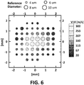
- Figure 6 shows a typical droplet pattern of a high pressure injection by the at least one electrically controlled fuel injector.
- the droplet size of the fuel injectors of Figure 6 is almost an order of magnitude lower than the size obtainable with the traditional nozzles of Figure 5 .
- the much lower average droplet size is greatly beneficial to ensure a constant and higher flame speed.
- the increased flame speed has also the following benefits:
Landscapes
- Engineering & Computer Science (AREA)
- Chemical & Material Sciences (AREA)
- Combustion & Propulsion (AREA)
- Mechanical Engineering (AREA)
- General Engineering & Computer Science (AREA)
- Electrical Control Of Air Or Fuel Supplied To Internal-Combustion Engine (AREA)
Claims (14)
- Kraftstoffregelsystem (1) für ein Gasturbinentriebwerk eines Luftfahrzeugs, mit:- einem Triebwerk (18) mit einem Getriebe (2) und einer Brennkammer (6),- einem Kraftstofftank (3) zur Aufbewahrung von Kraftstoff,- einer Hochdruck-Kraftstoffpumpe (9) zum Pumpen von Kraftstoff aus dem Kraftstofftank (3) zu der Brennkammer (6), und- einem Kraftstoffdrucksensor (11) der zur Erfassung des Drucks des gepumpten Kraftstoffs angeordnet ist,dadurch gekennzeichnet, dass das System (1) ferner aufweist:- mindestens eine elektrisch gesteuerte Kraftstoffeinspritzdüse (7), um eine Flussmenge des gepumpten Kraftstoffs in die Brennkammer (6) einzuspritzen,- einen Kraftstofftemperatursensor (12), der zur Erfassung der Temperatur des gepumpten Kraftstoffs angeordnet ist, und- einen Kraftstoffregler (5), der elektrisch mit den Kraftstoffdruck- und Temperatursensoren (11, 12) gekoppelt ist, um die Kraftstoffdichte gemäß den erfassten Werten zu berechnen,- wobei der Kraftstoffregler (5) elektrisch mit der mindestens einen Kraftstoffeinspritzdüse (7) gekoppelt ist, um die Kraftstoffflusseinspritzmenge zu bestimmen,- wobei der Kraftstoffregler (5) dazu ausgebildet ist, die Menge des eingespritzten Kraftstoffs in Abhängigkeit von der Kraftstoffdichte und der Kraftstoffflusseinspritzmenge zu berechnen,- wobei der Kraftstoffregler (5) elektrisch mit der Kraftstoffpumpe (9) gekoppelt ist, um einen Pumpenausgangsdruckwert in Abhängigkeit von der Menge des eingespritzten Kraftstoffs zu bestimmen, so dass der mindestens einen Kraftstoffeinspritzdüse (7) ein konstanter Kraftstoffdruckwert zugeführt wird, um einen konstanten Kraftstoffeinspritzdruck in die Brennkammer (6) einzuspritzen, und- wobei der Kraftstoffregler (5) ferner dazu ausgebildet ist, die Kraftstoffflusseinspritzmenge der mindestens einen Kraftstoffeinspritzdüse (7) zu regulieren, um die mindestens eine Kraftstoffeinspritzdüse (7) mit einem konstanten Kraftstoffdruckwert zu versorgen.
- Kraftstoffregelsystem (1) nach Anspruch 1, wobei das Triebwerk (18) eine Welle aufweist, und wobei das System (1) einen mit dem Triebwerk (18) gekoppelten Triebwerksdrehzahlsensor (14) aufweist, um den momentanen Drehzahlwert der Triebwerkswelle zu erfassen, und wobei der Kraftstoffregler (5) dazu ausgebildet ist, momentane Triebwerkslastinformationen (13) zu empfangen und den Kraftstoffpumpenausgangsdruckwert unter Berücksichtigung der Last- und Drehzahlwerte zu modifizieren, um die mindestens eine Kraftstoffeinspritzdüse (7) mit einem konstanten Kraftstoffdruckwert zu versorgen.
- Kraftstoffregelsystem (1) nach Anspruch 2, wobei der Kraftstoffregler (5) weiterhin dazu ausgebildet ist, den Arbeitszyklus der Kraftstoffpumpe (9) entsprechend den Last- und Drehzahlwerten derart zu verändern, dass die mindestens eine Kraftstoffeinspritzdüse (7) mit einem konstanten Kraftstoffdruckwert versorgt wird.
- Kraftstoffregelsystem (1) nach einem der Ansprüche 2 - 3, wobei die Kraftstoffpumpe (9) Einlassventile zum Aufnehmen des zu pumpenden Kraftstoffs aufweist, und wobei der Kraftstoffregler (5) ferner dazu ausgebildet ist, den Kraftstoffzufluss durch mindestens eines der Kraftstoffpumpeneinlassventile gemäß den Last- und/oder Drehzahlwerten zu reduzieren.
- Kraftstoffregelsystem (1) nach einem der vorhergehenden Ansprüche, mit ein Einlassluftströmungsdruck- (15) und einem Lufttemperatursensor (16), die beide in einem Triebwerkslufteinlass angeordnet sind, um Druck- und Temperaturwerte eines Einlassluftstroms zu erfassen, und wobei der Kraftstoffregler (5) dazu ausgebildet ist, den Kraftstoffpumpenausgangsdruckwert unter Berücksichtigung der Einlassluftströmungsdruck- und Temperaturwerte zu ändern, um die mindestens einen Kraftstoffeinspritzdüse (7) mit einem konstanten Kraftstoffdruckwert zu versorgen.
- Kraftstoffregelsystem (1) nach einem der Ansprüche 1 - 5, wobei der Kraftstoffregler (5) ferner dazu ausgebildet ist, den von der mindestens einen Kraftstoffeinspritzdüse (7) eingespritzten Kraftstoffdurchsatz unter Berücksichtigung der erfassten Werte zu verändern.
- Kraftstoffregelsystem (1) nach einem der vorhergehenden Ansprüche, mit einer Vielzahl von Kraftstoffeinspritzdüsen (7), und wobei der Kraftstoffregler (5) dazu ausgebildet ist, den Kraftstoffdurchsatz einer jeden Einspritzdüse (7) individuell zu regeln.
- Kraftstoffregelsystem (1) nach einem der vorhergehenden Ansprüche, wobei die Kraftstoffdruck- (11) und/oder Kraftstofftemperatursensoren (12) an einen Auslass der Kraftstoffpumpe (9) oder an eine Rohrleitung (17), die den gepumpten Kraftstoff zu der mindestens einen Kraftstoffeinspritzdüse (7) führt, gekoppelt sind.
- Kraftstoffregelsystem (1) nach einem der vorhergehenden Ansprüche, wobei die Kraftstoffpumpe (9) als mechanische oder elektrische Pumpe ausgebildet ist, und wobei für den Fall dass die Hochdruck-Kraftstoffpumpe (9) als mechanische Pumpe ausgebildet ist, die Pumpe mittels des Getriebes (2) mechanisch angetrieben wird.
- Kraftstoffregelsystem (1) nach Anspruch 9, wobei die mechanische Hochdruck-Kraftstoffpumpe (9) mittels des Getriebes (2) mechanisch angetrieben wird.
- Kraftstoffregelsystem (1) nach Anspruch 9, wobei die elektrische Kraftstoffpumpe (9) separat von dem Getriebe (2) angeordnet ist.
- Kraftstoffregelsystem (1) nach einem der vorhergehenden Ansprüche, mit einem Linearmotor, wobei die Kraftstoffpumpe (9) von dem Linearmotor angetrieben wird.
- Kraftstoffregelsystem (1) nach einem der vorhergehenden Ansprüche, wobei die mindestens eine Kraftstoffpumpe (9) in jede der mindestens einen Kraftstoffeinspritzdüsen (7) integriert ist.
- Luftfahrzeug mit einem Kraftstoffregelsystem (1) nach einem der vorhergehenden Ansprüche.
Priority Applications (3)
| Application Number | Priority Date | Filing Date | Title |
|---|---|---|---|
| EP15382618.5A EP3179077B1 (de) | 2015-12-11 | 2015-12-11 | Kraftstoffregelsystem für gasturbinenmotor eines flugzeugs |
| ES15382618T ES2698380T3 (es) | 2015-12-11 | 2015-12-11 | Sistema de control de combustible para un motor de turbina de gas de una aeronave |
| US15/372,645 US20170167391A1 (en) | 2015-12-11 | 2016-12-08 | Fuel Control System For A Gas Turbine Engine Of An Aircraft |
Applications Claiming Priority (1)
| Application Number | Priority Date | Filing Date | Title |
|---|---|---|---|
| EP15382618.5A EP3179077B1 (de) | 2015-12-11 | 2015-12-11 | Kraftstoffregelsystem für gasturbinenmotor eines flugzeugs |
Publications (2)
| Publication Number | Publication Date |
|---|---|
| EP3179077A1 EP3179077A1 (de) | 2017-06-14 |
| EP3179077B1 true EP3179077B1 (de) | 2018-09-12 |
Family
ID=55085520
Family Applications (1)
| Application Number | Title | Priority Date | Filing Date |
|---|---|---|---|
| EP15382618.5A Not-in-force EP3179077B1 (de) | 2015-12-11 | 2015-12-11 | Kraftstoffregelsystem für gasturbinenmotor eines flugzeugs |
Country Status (3)
| Country | Link |
|---|---|
| US (1) | US20170167391A1 (de) |
| EP (1) | EP3179077B1 (de) |
| ES (1) | ES2698380T3 (de) |
Families Citing this family (18)
| Publication number | Priority date | Publication date | Assignee | Title |
|---|---|---|---|---|
| GB2578106A (en) * | 2018-10-15 | 2020-04-22 | Eaton Intelligent Power Ltd | Variable demand fuel pump |
| US10974844B2 (en) * | 2019-01-29 | 2021-04-13 | The Boeing Company | Aircraft auxiliary power unit (APU) control system having speed compensation |
| US10988266B2 (en) * | 2019-01-29 | 2021-04-27 | The Boeing Company | Aircraft auxiliary power unit (APU) control system having speed compensation |
| US11034463B2 (en) | 2019-03-26 | 2021-06-15 | The Boeing Company | Aircraft auxiliary power unit (APU) control system having variably sized air inlet |
| FR3094961B1 (fr) * | 2019-04-12 | 2022-08-26 | Safran Helicopter Engines | Installation propulsive hybride et procédé de commande d’une telle installation |
| FR3098255B1 (fr) * | 2019-07-03 | 2021-06-04 | Safran Aircraft Engines | Détermination de densité de carburant pour dosage de carburant dans un circuit d’alimentation en carburant d’un moteur d’aéronef |
| WO2021039903A1 (ja) * | 2019-08-30 | 2021-03-04 | 川崎重工業株式会社 | ガスタービンエンジン |
| PL431661A1 (pl) * | 2019-10-30 | 2021-05-04 | General Electric Company | Układ i sposób działania komory spalania z wieloma paliwami ciekłymi |
| US11635031B2 (en) * | 2019-11-08 | 2023-04-25 | Hamilton Sundstrand Corporation | Simultaneously pumping and measuring density of aircraft fuel |
| US11629717B2 (en) | 2019-11-08 | 2023-04-18 | Hamilton Sundstrand Corporation | Simultaneously pumping and measuring density of aircraft fuel |
| RU2753207C1 (ru) * | 2020-10-14 | 2021-08-12 | Федеральное Автономное Учреждение "Центральный институт авиационного моторостроения имени П.И. Баранова" | Система подачи топлива в многоколлекторную камеру сгорания |
| CN115492687B (zh) * | 2021-06-17 | 2025-11-04 | 通用电气公司 | 管理热燃料的控制方法 |
| US11821366B2 (en) | 2021-06-17 | 2023-11-21 | General Electric Company | Methods of control for management of hot fuel |
| US11668241B2 (en) * | 2021-06-17 | 2023-06-06 | General Electric Company | Methods of control for management of hot fuel |
| US12031492B2 (en) | 2021-10-12 | 2024-07-09 | Hamilton Sundstrand Corporation | Electric fuel control closed loop aircraft fuel system |
| GB202201316D0 (en) * | 2022-02-02 | 2022-03-16 | Rolls Royce Plc | Combination of a gas turbine engine and a power electronics |
| GB202201313D0 (en) | 2022-02-02 | 2022-03-16 | Rolls Royce Plc | Combination of a gas turbine engine and a power electronics |
| CN114718737B (zh) * | 2022-04-11 | 2023-09-05 | 中国航发控制系统研究所 | 一种电动燃油泵的流量开环控制方法 |
Family Cites Families (15)
| Publication number | Priority date | Publication date | Assignee | Title |
|---|---|---|---|---|
| US2730167A (en) * | 1950-03-08 | 1956-01-10 | Chrysler Corp | Control apparatus |
| US3157221A (en) * | 1961-08-07 | 1964-11-17 | Holley Carburetor Co | Fluid supply system |
| US4508127A (en) * | 1983-03-30 | 1985-04-02 | The Garrett Corporation | Fuel mass flow measurement and control system |
| US4747262A (en) * | 1985-10-04 | 1988-05-31 | Allied-Signal, Inc. | Compressor power unit fuel flow control |
| US5274996A (en) * | 1991-10-11 | 1994-01-04 | Allied-Signal, Inc. | Closed loop fuel control system |
| JPH05195839A (ja) * | 1992-01-22 | 1993-08-03 | Mitsubishi Electric Corp | 内燃機関の電子制御装置 |
| US5351893A (en) * | 1993-05-26 | 1994-10-04 | Young Niels O | Electromagnetic fuel injector linear motor and pump |
| CA2634756C (en) * | 2005-12-22 | 2014-07-08 | William Henry Scalia, Jr. | Apparatus and method for fuel flow rate, fuel temperature, fuel droplet size, and burner firing rate modulation |
| JP2011043136A (ja) * | 2009-08-24 | 2011-03-03 | Honda Motor Co Ltd | ガスタービン・エンジンの始動時燃料制御装置 |
| US8666632B2 (en) * | 2011-04-20 | 2014-03-04 | Hamilton Sundstrand Corporation | Distributed aircraft engine fuel system |
| US20120324905A1 (en) * | 2011-06-27 | 2012-12-27 | Behzad Hagshenas | Apu fuel system and method |
| US20140294559A1 (en) * | 2013-03-28 | 2014-10-02 | Solar Turbines Incorporated | Multiple mode gas turbine engine gas fuel system with integrated control |
| WO2015095763A1 (en) * | 2013-12-19 | 2015-06-25 | United Technologies Corporation | Self-pumping fuel injector for a gas turbine engine and method of operation |
| US9982669B2 (en) * | 2014-11-06 | 2018-05-29 | Caterpillar Inc. | Variable retraction rate pump and method for operating same |
| US9752530B2 (en) * | 2014-12-15 | 2017-09-05 | Ford Global Technologies, Llc | Methods and systems for fixed and variable pressure fuel injection |
-
2015
- 2015-12-11 EP EP15382618.5A patent/EP3179077B1/de not_active Not-in-force
- 2015-12-11 ES ES15382618T patent/ES2698380T3/es active Active
-
2016
- 2016-12-08 US US15/372,645 patent/US20170167391A1/en not_active Abandoned
Non-Patent Citations (1)
| Title |
|---|
| None * |
Also Published As
| Publication number | Publication date |
|---|---|
| ES2698380T3 (es) | 2019-02-04 |
| EP3179077A1 (de) | 2017-06-14 |
| US20170167391A1 (en) | 2017-06-15 |
Similar Documents
| Publication | Publication Date | Title |
|---|---|---|
| EP3179077A1 (de) | Kraftstoffregelsystem für gasturbinenmotor eines flugzeugs | |
| US8256222B2 (en) | Direct metering fuel control with integral electrical metering pump and actuator servo pump | |
| US8127548B2 (en) | Hybrid electrical/mechanical turbine engine fuel supply system | |
| US7966995B2 (en) | Dual level pressurization control based on fuel flow to one or more gas turbine engine secondary fuel loads | |
| US8291886B2 (en) | Actuator flow compensated direct metering fuel control system and method | |
| RU2531840C2 (ru) | Контур подачи топлива для авиационного двигателя | |
| US7895819B2 (en) | Assistance and emergency backup for the electrical drive of a fuel pump in a turbine engine | |
| US8991148B2 (en) | Fuel feed device for aviation engine | |
| US20120117974A1 (en) | Air flow delivery and fuel consumption control for aircraft air management and auxiliary power systems | |
| US20180050812A1 (en) | Aircraft fuel pump systems | |
| EP2485109B1 (de) | Direktes Kraftstoffmesssystem mit konstantem Servofluss | |
| US20140205472A1 (en) | Dual pump/dual bypass fuel pumping system | |
| US7197879B2 (en) | Multiple electric fuel metering systems for gas turbine applications | |
| US10584644B2 (en) | Fuel injection system and method of controlling the same | |
| US20120204532A1 (en) | Fuel supply system with multiple pumping means | |
| CN115324743B (zh) | 一种气电混合驱动泵的低温升发动机燃油系统 | |
| KR101685853B1 (ko) | 이중 연료 내연 기관 추진 장치 | |
| KR101232393B1 (ko) | 터빈 발전기의 제어 방법 및 장치 | |
| EP3203053B1 (de) | Gasturbinentriebwerkkraftstoffsystem | |
| JP3910057B2 (ja) | 燃料計量ユニットによって制御される2レベル加圧バルブ | |
| US20250084838A1 (en) | Variable displacement pump (vdp) systems with dual dry out pumps | |
| US12031492B2 (en) | Electric fuel control closed loop aircraft fuel system | |
| US11982239B2 (en) | Gas turbine engine system with mixed flow auxiliary power unit | |
| EP3770405A1 (de) | Kraftstoffzuführsystem und -verfahren | |
| US12366207B2 (en) | Variable displacement pump (VDP) systems with dry-out centrifugal main pump |
Legal Events
| Date | Code | Title | Description |
|---|---|---|---|
| PUAI | Public reference made under article 153(3) epc to a published international application that has entered the european phase |
Free format text: ORIGINAL CODE: 0009012 |
|
| STAA | Information on the status of an ep patent application or granted ep patent |
Free format text: STATUS: THE APPLICATION HAS BEEN PUBLISHED |
|
| AK | Designated contracting states |
Kind code of ref document: A1 Designated state(s): AL AT BE BG CH CY CZ DE DK EE ES FI FR GB GR HR HU IE IS IT LI LT LU LV MC MK MT NL NO PL PT RO RS SE SI SK SM TR |
|
| AX | Request for extension of the european patent |
Extension state: BA ME |
|
| STAA | Information on the status of an ep patent application or granted ep patent |
Free format text: STATUS: REQUEST FOR EXAMINATION WAS MADE |
|
| 17P | Request for examination filed |
Effective date: 20171213 |
|
| RBV | Designated contracting states (corrected) |
Designated state(s): AL AT BE BG CH CY CZ DE DK EE ES FI FR GB GR HR HU IE IS IT LI LT LU LV MC MK MT NL NO PL PT RO RS SE SI SK SM TR |
|
| GRAP | Despatch of communication of intention to grant a patent |
Free format text: ORIGINAL CODE: EPIDOSNIGR1 |
|
| STAA | Information on the status of an ep patent application or granted ep patent |
Free format text: STATUS: GRANT OF PATENT IS INTENDED |
|
| RIC1 | Information provided on ipc code assigned before grant |
Ipc: F02C 7/22 20060101AFI20180323BHEP Ipc: F02C 7/232 20060101ALI20180323BHEP Ipc: F02C 9/30 20060101ALI20180323BHEP Ipc: F02C 9/28 20060101ALI20180323BHEP |
|
| INTG | Intention to grant announced |
Effective date: 20180423 |
|
| GRAS | Grant fee paid |
Free format text: ORIGINAL CODE: EPIDOSNIGR3 |
|
| GRAA | (expected) grant |
Free format text: ORIGINAL CODE: 0009210 |
|
| STAA | Information on the status of an ep patent application or granted ep patent |
Free format text: STATUS: THE PATENT HAS BEEN GRANTED |
|
| AK | Designated contracting states |
Kind code of ref document: B1 Designated state(s): AL AT BE BG CH CY CZ DE DK EE ES FI FR GB GR HR HU IE IS IT LI LT LU LV MC MK MT NL NO PL PT RO RS SE SI SK SM TR |
|
| REG | Reference to a national code |
Ref country code: GB Ref legal event code: FG4D |
|
| REG | Reference to a national code |
Ref country code: CH Ref legal event code: EP |
|
| REG | Reference to a national code |
Ref country code: IE Ref legal event code: FG4D |
|
| REG | Reference to a national code |
Ref country code: AT Ref legal event code: REF Ref document number: 1040865 Country of ref document: AT Kind code of ref document: T Effective date: 20181015 |
|
| REG | Reference to a national code |
Ref country code: DE Ref legal event code: R096 Ref document number: 602015016036 Country of ref document: DE |
|
| REG | Reference to a national code |
Ref country code: NL Ref legal event code: MP Effective date: 20180912 |
|
| REG | Reference to a national code |
Ref country code: LT Ref legal event code: MG4D |
|
| PG25 | Lapsed in a contracting state [announced via postgrant information from national office to epo] |
Ref country code: FI Free format text: LAPSE BECAUSE OF FAILURE TO SUBMIT A TRANSLATION OF THE DESCRIPTION OR TO PAY THE FEE WITHIN THE PRESCRIBED TIME-LIMIT Effective date: 20180912 Ref country code: SE Free format text: LAPSE BECAUSE OF FAILURE TO SUBMIT A TRANSLATION OF THE DESCRIPTION OR TO PAY THE FEE WITHIN THE PRESCRIBED TIME-LIMIT Effective date: 20180912 Ref country code: GR Free format text: LAPSE BECAUSE OF FAILURE TO SUBMIT A TRANSLATION OF THE DESCRIPTION OR TO PAY THE FEE WITHIN THE PRESCRIBED TIME-LIMIT Effective date: 20181213 Ref country code: RS Free format text: LAPSE BECAUSE OF FAILURE TO SUBMIT A TRANSLATION OF THE DESCRIPTION OR TO PAY THE FEE WITHIN THE PRESCRIBED TIME-LIMIT Effective date: 20180912 Ref country code: NO Free format text: LAPSE BECAUSE OF FAILURE TO SUBMIT A TRANSLATION OF THE DESCRIPTION OR TO PAY THE FEE WITHIN THE PRESCRIBED TIME-LIMIT Effective date: 20181212 Ref country code: LT Free format text: LAPSE BECAUSE OF FAILURE TO SUBMIT A TRANSLATION OF THE DESCRIPTION OR TO PAY THE FEE WITHIN THE PRESCRIBED TIME-LIMIT Effective date: 20180912 Ref country code: BG Free format text: LAPSE BECAUSE OF FAILURE TO SUBMIT A TRANSLATION OF THE DESCRIPTION OR TO PAY THE FEE WITHIN THE PRESCRIBED TIME-LIMIT Effective date: 20181212 |
|
| REG | Reference to a national code |
Ref country code: ES Ref legal event code: FG2A Ref document number: 2698380 Country of ref document: ES Kind code of ref document: T3 Effective date: 20190204 |
|
| PG25 | Lapsed in a contracting state [announced via postgrant information from national office to epo] |
Ref country code: HR Free format text: LAPSE BECAUSE OF FAILURE TO SUBMIT A TRANSLATION OF THE DESCRIPTION OR TO PAY THE FEE WITHIN THE PRESCRIBED TIME-LIMIT Effective date: 20180912 Ref country code: LV Free format text: LAPSE BECAUSE OF FAILURE TO SUBMIT A TRANSLATION OF THE DESCRIPTION OR TO PAY THE FEE WITHIN THE PRESCRIBED TIME-LIMIT Effective date: 20180912 Ref country code: AL Free format text: LAPSE BECAUSE OF FAILURE TO SUBMIT A TRANSLATION OF THE DESCRIPTION OR TO PAY THE FEE WITHIN THE PRESCRIBED TIME-LIMIT Effective date: 20180912 |
|
| REG | Reference to a national code |
Ref country code: AT Ref legal event code: MK05 Ref document number: 1040865 Country of ref document: AT Kind code of ref document: T Effective date: 20180912 |
|
| PG25 | Lapsed in a contracting state [announced via postgrant information from national office to epo] |
Ref country code: AT Free format text: LAPSE BECAUSE OF FAILURE TO SUBMIT A TRANSLATION OF THE DESCRIPTION OR TO PAY THE FEE WITHIN THE PRESCRIBED TIME-LIMIT Effective date: 20180912 Ref country code: IS Free format text: LAPSE BECAUSE OF FAILURE TO SUBMIT A TRANSLATION OF THE DESCRIPTION OR TO PAY THE FEE WITHIN THE PRESCRIBED TIME-LIMIT Effective date: 20190112 Ref country code: PL Free format text: LAPSE BECAUSE OF FAILURE TO SUBMIT A TRANSLATION OF THE DESCRIPTION OR TO PAY THE FEE WITHIN THE PRESCRIBED TIME-LIMIT Effective date: 20180912 Ref country code: RO Free format text: LAPSE BECAUSE OF FAILURE TO SUBMIT A TRANSLATION OF THE DESCRIPTION OR TO PAY THE FEE WITHIN THE PRESCRIBED TIME-LIMIT Effective date: 20180912 Ref country code: CZ Free format text: LAPSE BECAUSE OF FAILURE TO SUBMIT A TRANSLATION OF THE DESCRIPTION OR TO PAY THE FEE WITHIN THE PRESCRIBED TIME-LIMIT Effective date: 20180912 Ref country code: NL Free format text: LAPSE BECAUSE OF FAILURE TO SUBMIT A TRANSLATION OF THE DESCRIPTION OR TO PAY THE FEE WITHIN THE PRESCRIBED TIME-LIMIT Effective date: 20180912 Ref country code: IT Free format text: LAPSE BECAUSE OF FAILURE TO SUBMIT A TRANSLATION OF THE DESCRIPTION OR TO PAY THE FEE WITHIN THE PRESCRIBED TIME-LIMIT Effective date: 20180912 Ref country code: EE Free format text: LAPSE BECAUSE OF FAILURE TO SUBMIT A TRANSLATION OF THE DESCRIPTION OR TO PAY THE FEE WITHIN THE PRESCRIBED TIME-LIMIT Effective date: 20180912 |
|
| PG25 | Lapsed in a contracting state [announced via postgrant information from national office to epo] |
Ref country code: SM Free format text: LAPSE BECAUSE OF FAILURE TO SUBMIT A TRANSLATION OF THE DESCRIPTION OR TO PAY THE FEE WITHIN THE PRESCRIBED TIME-LIMIT Effective date: 20180912 Ref country code: PT Free format text: LAPSE BECAUSE OF FAILURE TO SUBMIT A TRANSLATION OF THE DESCRIPTION OR TO PAY THE FEE WITHIN THE PRESCRIBED TIME-LIMIT Effective date: 20190112 Ref country code: SK Free format text: LAPSE BECAUSE OF FAILURE TO SUBMIT A TRANSLATION OF THE DESCRIPTION OR TO PAY THE FEE WITHIN THE PRESCRIBED TIME-LIMIT Effective date: 20180912 |
|
| REG | Reference to a national code |
Ref country code: DE Ref legal event code: R097 Ref document number: 602015016036 Country of ref document: DE |
|
| PLBE | No opposition filed within time limit |
Free format text: ORIGINAL CODE: 0009261 |
|
| STAA | Information on the status of an ep patent application or granted ep patent |
Free format text: STATUS: NO OPPOSITION FILED WITHIN TIME LIMIT |
|
| PG25 | Lapsed in a contracting state [announced via postgrant information from national office to epo] |
Ref country code: DK Free format text: LAPSE BECAUSE OF FAILURE TO SUBMIT A TRANSLATION OF THE DESCRIPTION OR TO PAY THE FEE WITHIN THE PRESCRIBED TIME-LIMIT Effective date: 20180912 |
|
| REG | Reference to a national code |
Ref country code: CH Ref legal event code: PL |
|
| 26N | No opposition filed |
Effective date: 20190613 |
|
| PG25 | Lapsed in a contracting state [announced via postgrant information from national office to epo] |
Ref country code: SI Free format text: LAPSE BECAUSE OF FAILURE TO SUBMIT A TRANSLATION OF THE DESCRIPTION OR TO PAY THE FEE WITHIN THE PRESCRIBED TIME-LIMIT Effective date: 20180912 Ref country code: MC Free format text: LAPSE BECAUSE OF FAILURE TO SUBMIT A TRANSLATION OF THE DESCRIPTION OR TO PAY THE FEE WITHIN THE PRESCRIBED TIME-LIMIT Effective date: 20180912 Ref country code: LU Free format text: LAPSE BECAUSE OF NON-PAYMENT OF DUE FEES Effective date: 20181211 |
|
| REG | Reference to a national code |
Ref country code: IE Ref legal event code: MM4A |
|
| REG | Reference to a national code |
Ref country code: BE Ref legal event code: MM Effective date: 20181231 |
|
| PG25 | Lapsed in a contracting state [announced via postgrant information from national office to epo] |
Ref country code: IE Free format text: LAPSE BECAUSE OF NON-PAYMENT OF DUE FEES Effective date: 20181211 |
|
| PG25 | Lapsed in a contracting state [announced via postgrant information from national office to epo] |
Ref country code: BE Free format text: LAPSE BECAUSE OF NON-PAYMENT OF DUE FEES Effective date: 20181231 |
|
| PG25 | Lapsed in a contracting state [announced via postgrant information from national office to epo] |
Ref country code: LI Free format text: LAPSE BECAUSE OF NON-PAYMENT OF DUE FEES Effective date: 20181231 Ref country code: CH Free format text: LAPSE BECAUSE OF NON-PAYMENT OF DUE FEES Effective date: 20181231 |
|
| PG25 | Lapsed in a contracting state [announced via postgrant information from national office to epo] |
Ref country code: MT Free format text: LAPSE BECAUSE OF NON-PAYMENT OF DUE FEES Effective date: 20181211 |
|
| PG25 | Lapsed in a contracting state [announced via postgrant information from national office to epo] |
Ref country code: TR Free format text: LAPSE BECAUSE OF FAILURE TO SUBMIT A TRANSLATION OF THE DESCRIPTION OR TO PAY THE FEE WITHIN THE PRESCRIBED TIME-LIMIT Effective date: 20180912 |
|
| PG25 | Lapsed in a contracting state [announced via postgrant information from national office to epo] |
Ref country code: HU Free format text: LAPSE BECAUSE OF FAILURE TO SUBMIT A TRANSLATION OF THE DESCRIPTION OR TO PAY THE FEE WITHIN THE PRESCRIBED TIME-LIMIT; INVALID AB INITIO Effective date: 20151211 Ref country code: MK Free format text: LAPSE BECAUSE OF NON-PAYMENT OF DUE FEES Effective date: 20180912 Ref country code: CY Free format text: LAPSE BECAUSE OF FAILURE TO SUBMIT A TRANSLATION OF THE DESCRIPTION OR TO PAY THE FEE WITHIN THE PRESCRIBED TIME-LIMIT Effective date: 20180912 |
|
| PGFP | Annual fee paid to national office [announced via postgrant information from national office to epo] |
Ref country code: GB Payment date: 20231220 Year of fee payment: 9 |
|
| PGFP | Annual fee paid to national office [announced via postgrant information from national office to epo] |
Ref country code: FR Payment date: 20231221 Year of fee payment: 9 Ref country code: DE Payment date: 20231214 Year of fee payment: 9 |
|
| PGFP | Annual fee paid to national office [announced via postgrant information from national office to epo] |
Ref country code: ES Payment date: 20240129 Year of fee payment: 9 |
|
| REG | Reference to a national code |
Ref country code: DE Ref legal event code: R119 Ref document number: 602015016036 Country of ref document: DE |
|
| GBPC | Gb: european patent ceased through non-payment of renewal fee |
Effective date: 20241211 |
|
| PG25 | Lapsed in a contracting state [announced via postgrant information from national office to epo] |
Ref country code: DE Free format text: LAPSE BECAUSE OF NON-PAYMENT OF DUE FEES Effective date: 20250701 |
|
| PG25 | Lapsed in a contracting state [announced via postgrant information from national office to epo] |
Ref country code: GB Free format text: LAPSE BECAUSE OF NON-PAYMENT OF DUE FEES Effective date: 20241211 |
|
| PG25 | Lapsed in a contracting state [announced via postgrant information from national office to epo] |
Ref country code: FR Free format text: LAPSE BECAUSE OF NON-PAYMENT OF DUE FEES Effective date: 20241231 |
|
| REG | Reference to a national code |
Ref country code: ES Ref legal event code: FD2A Effective date: 20260130 |
|
| PG25 | Lapsed in a contracting state [announced via postgrant information from national office to epo] |
Ref country code: ES Free format text: LAPSE BECAUSE OF NON-PAYMENT OF DUE FEES Effective date: 20241212 |