EP3689181A1 - Kosmetikbehälter mit nachfüllbarem innenbehälter - Google Patents
Kosmetikbehälter mit nachfüllbarem innenbehälter Download PDFInfo
- Publication number
- EP3689181A1 EP3689181A1 EP19798148.3A EP19798148A EP3689181A1 EP 3689181 A1 EP3689181 A1 EP 3689181A1 EP 19798148 A EP19798148 A EP 19798148A EP 3689181 A1 EP3689181 A1 EP 3689181A1
- Authority
- EP
- European Patent Office
- Prior art keywords
- container
- inner container
- cosmetic
- container body
- pump
- Prior art date
- Legal status (The legal status is an assumption and is not a legal conclusion. Google has not performed a legal analysis and makes no representation as to the accuracy of the status listed.)
- Granted
Links
Images


Classifications
-
- A—HUMAN NECESSITIES
- A45—HAND OR TRAVELLING ARTICLES
- A45D—HAIRDRESSING OR SHAVING EQUIPMENT; EQUIPMENT FOR COSMETICS OR COSMETIC TREATMENTS, e.g. FOR MANICURING OR PEDICURING
- A45D34/00—Containers or accessories specially adapted for handling liquid toiletry or cosmetic substances, e.g. perfumes
- A45D34/04—Appliances specially adapted for applying liquid, e.g. using roller or ball
-
- A—HUMAN NECESSITIES
- A45—HAND OR TRAVELLING ARTICLES
- A45D—HAIRDRESSING OR SHAVING EQUIPMENT; EQUIPMENT FOR COSMETICS OR COSMETIC TREATMENTS, e.g. FOR MANICURING OR PEDICURING
- A45D33/00—Containers or accessories specially adapted for handling powdery toiletry or cosmetic substances
-
- A—HUMAN NECESSITIES
- A45—HAND OR TRAVELLING ARTICLES
- A45D—HAIRDRESSING OR SHAVING EQUIPMENT; EQUIPMENT FOR COSMETICS OR COSMETIC TREATMENTS, e.g. FOR MANICURING OR PEDICURING
- A45D33/00—Containers or accessories specially adapted for handling powdery toiletry or cosmetic substances
- A45D33/20—Containers with movably mounted drawers
-
- A—HUMAN NECESSITIES
- A45—HAND OR TRAVELLING ARTICLES
- A45D—HAIRDRESSING OR SHAVING EQUIPMENT; EQUIPMENT FOR COSMETICS OR COSMETIC TREATMENTS, e.g. FOR MANICURING OR PEDICURING
- A45D40/00—Casings or accessories specially adapted for storing or handling solid or pasty toiletry or cosmetic substances, e.g. shaving soaps or lipsticks
- A45D40/14—Casings with ejector for waste stick or the like
-
- A—HUMAN NECESSITIES
- A45—HAND OR TRAVELLING ARTICLES
- A45D—HAIRDRESSING OR SHAVING EQUIPMENT; EQUIPMENT FOR COSMETICS OR COSMETIC TREATMENTS, e.g. FOR MANICURING OR PEDICURING
- A45D40/00—Casings or accessories specially adapted for storing or handling solid or pasty toiletry or cosmetic substances, e.g. shaving soaps or lipsticks
- A45D40/16—Refill sticks; Moulding devices for producing sticks
-
- A—HUMAN NECESSITIES
- A45—HAND OR TRAVELLING ARTICLES
- A45D—HAIRDRESSING OR SHAVING EQUIPMENT; EQUIPMENT FOR COSMETICS OR COSMETIC TREATMENTS, e.g. FOR MANICURING OR PEDICURING
- A45D40/00—Casings or accessories specially adapted for storing or handling solid or pasty toiletry or cosmetic substances, e.g. shaving soaps or lipsticks
- A45D40/26—Appliances specially adapted for applying pasty paint, e.g. using roller, using a ball
-
- B—PERFORMING OPERATIONS; TRANSPORTING
- B05—SPRAYING OR ATOMISING IN GENERAL; APPLYING FLUENT MATERIALS TO SURFACES, IN GENERAL
- B05C—APPARATUS FOR APPLYING FLUENT MATERIALS TO SURFACES, IN GENERAL
- B05C11/00—Component parts, details or accessories not specifically provided for in groups B05C1/00 - B05C9/00
- B05C11/10—Storage, supply or control of liquid or other fluent material; Recovery of excess liquid or other fluent material
- B05C11/1002—Means for controlling supply, i.e. flow or pressure, of liquid or other fluent material to the applying apparatus, e.g. valves
-
- B—PERFORMING OPERATIONS; TRANSPORTING
- B65—CONVEYING; PACKING; STORING; HANDLING THIN OR FILAMENTARY MATERIAL
- B65D—CONTAINERS FOR STORAGE OR TRANSPORT OF ARTICLES OR MATERIALS, e.g. BAGS, BARRELS, BOTTLES, BOXES, CANS, CARTONS, CRATES, DRUMS, JARS, TANKS, HOPPERS, FORWARDING CONTAINERS; ACCESSORIES, CLOSURES, OR FITTINGS THEREFOR; PACKAGING ELEMENTS; PACKAGES
- B65D25/00—Details of other kinds or types of rigid or semi-rigid containers
- B65D25/02—Internal fittings
-
- B—PERFORMING OPERATIONS; TRANSPORTING
- B65—CONVEYING; PACKING; STORING; HANDLING THIN OR FILAMENTARY MATERIAL
- B65D—CONTAINERS FOR STORAGE OR TRANSPORT OF ARTICLES OR MATERIALS, e.g. BAGS, BARRELS, BOTTLES, BOXES, CANS, CARTONS, CRATES, DRUMS, JARS, TANKS, HOPPERS, FORWARDING CONTAINERS; ACCESSORIES, CLOSURES, OR FITTINGS THEREFOR; PACKAGING ELEMENTS; PACKAGES
- B65D83/00—Containers or packages with special means for dispensing contents
- B65D83/771—Containers or packages with special means for dispensing contents for dispensing fluent contents by means of a flexible bag or a deformable membrane or diaphragm
-
- A—HUMAN NECESSITIES
- A45—HAND OR TRAVELLING ARTICLES
- A45D—HAIRDRESSING OR SHAVING EQUIPMENT; EQUIPMENT FOR COSMETICS OR COSMETIC TREATMENTS, e.g. FOR MANICURING OR PEDICURING
- A45D34/00—Containers or accessories specially adapted for handling liquid toiletry or cosmetic substances, e.g. perfumes
- A45D2034/002—Accessories
-
- A—HUMAN NECESSITIES
- A45—HAND OR TRAVELLING ARTICLES
- A45D—HAIRDRESSING OR SHAVING EQUIPMENT; EQUIPMENT FOR COSMETICS OR COSMETIC TREATMENTS, e.g. FOR MANICURING OR PEDICURING
- A45D34/00—Containers or accessories specially adapted for handling liquid toiletry or cosmetic substances, e.g. perfumes
- A45D2034/005—Containers or accessories specially adapted for handling liquid toiletry or cosmetic substances, e.g. perfumes with a cartridge
-
- A—HUMAN NECESSITIES
- A45—HAND OR TRAVELLING ARTICLES
- A45D—HAIRDRESSING OR SHAVING EQUIPMENT; EQUIPMENT FOR COSMETICS OR COSMETIC TREATMENTS, e.g. FOR MANICURING OR PEDICURING
- A45D40/00—Casings or accessories specially adapted for storing or handling solid or pasty toiletry or cosmetic substances, e.g. shaving soaps or lipsticks
- A45D2040/0006—Accessories
-
- A—HUMAN NECESSITIES
- A45—HAND OR TRAVELLING ARTICLES
- A45D—HAIRDRESSING OR SHAVING EQUIPMENT; EQUIPMENT FOR COSMETICS OR COSMETIC TREATMENTS, e.g. FOR MANICURING OR PEDICURING
- A45D2200/00—Details not otherwise provided for in A45D
- A45D2200/05—Details of containers
- A45D2200/054—Means for supplying liquid to the outlet of the container
-
- A—HUMAN NECESSITIES
- A45—HAND OR TRAVELLING ARTICLES
- A45D—HAIRDRESSING OR SHAVING EQUIPMENT; EQUIPMENT FOR COSMETICS OR COSMETIC TREATMENTS, e.g. FOR MANICURING OR PEDICURING
- A45D2200/00—Details not otherwise provided for in A45D
- A45D2200/05—Details of containers
- A45D2200/054—Means for supplying liquid to the outlet of the container
- A45D2200/055—Piston or plunger for supplying the liquid to the applicator
-
- A—HUMAN NECESSITIES
- A45—HAND OR TRAVELLING ARTICLES
- A45D—HAIRDRESSING OR SHAVING EQUIPMENT; EQUIPMENT FOR COSMETICS OR COSMETIC TREATMENTS, e.g. FOR MANICURING OR PEDICURING
- A45D2200/00—Details not otherwise provided for in A45D
- A45D2200/05—Details of containers
- A45D2200/054—Means for supplying liquid to the outlet of the container
- A45D2200/056—Reciprocating pumps, i.e. with variable volume chamber wherein pressure and vacuum are alternately generated
-
- A—HUMAN NECESSITIES
- A45—HAND OR TRAVELLING ARTICLES
- A45D—HAIRDRESSING OR SHAVING EQUIPMENT; EQUIPMENT FOR COSMETICS OR COSMETIC TREATMENTS, e.g. FOR MANICURING OR PEDICURING
- A45D2200/00—Details not otherwise provided for in A45D
- A45D2200/05—Details of containers
- A45D2200/054—Means for supplying liquid to the outlet of the container
- A45D2200/057—Spray nozzles; Generating atomised liquid
-
- A—HUMAN NECESSITIES
- A45—HAND OR TRAVELLING ARTICLES
- A45D—HAIRDRESSING OR SHAVING EQUIPMENT; EQUIPMENT FOR COSMETICS OR COSMETIC TREATMENTS, e.g. FOR MANICURING OR PEDICURING
- A45D40/00—Casings or accessories specially adapted for storing or handling solid or pasty toiletry or cosmetic substances, e.g. shaving soaps or lipsticks
- A45D40/22—Casings characterised by a hinged cover
Definitions
- the present invention relates to a cosmetic container, and more particularly, to a cosmetic container including a refillable inner container.
- a cosmetic container is a container which mainly accommodates cosmetic materials therein such that a user takes cosmetic materials accommodated in the compact container using a separate cosmetic tool such as a puff and applies cosmetic materials to a human body, such as a face, a body, and the like of the user, to simply apply makeup.
- Cosmetic compact containers are manufactured to have a variety of general shapes such as a circular shape and a quadrangular shape and designed to have a relatively small volume to be carried easily.
- Such cosmetic compact containers are used for accommodating not only cosmetic materials for color makeup such as powder-type finishing powder and solid-type compressed powder but also fluid-type cosmetic materials including liquid-type foundation as cosmetic materials for color makeup and gel-type sun cream as cosmetic materials for skincare.
- the present invention is directed to providing a novel cosmetic container in which only an inner container which accommodates cosmetic materials is replaceable more easily while a cosmetic container body remains as it is.
- the present invention is also directed to providing a refillable cosmetic container having a novel structure in which an inner container for a refill is attachable or detachable through a side surface of a container body such that the inner container for a refill may be easily attached or detached with only one hand.
- the present invention is also directed to providing a cosmetic container in which when an inner container coupled inside a container body is pressurized, as much of cosmetic materials sealed hygienically in the inner container as needed are discharged outward so as to provide fresh cosmetic materials which are not contaminated by bacteria.
- One aspect of the present invention provides a cosmetic container including an inner container in which contents are stored, a container body in which the inner container is accommodated, a discharge means configured to discharge the contents accommodated in the inner container, a distributor configured to distribute the contents discharged by the discharge means, and an upper cap configured to seal the container body.
- an open portion is formed on one side of the container body, the inner container is insertable into the container body through the open portion, and the inner container is separable from the container body through the open portion.
- the open portion may be formed on a side surface of the container body.
- the discharge means may include a pump and a pump nozzle.
- the pump may be formed in the inner container, the pump nozzle may be formed in the distributor, and the pump may be coupled with the pump nozzle when the inner container is inserted into the container body.
- the pump may be an airless pump or a dip-tube type pump.
- the inner container may include a movable film or a movable piston or may be a contractible pouch type.
- the contents accommodated in the inner container may be discharged into the distributor by the discharge means.
- the cosmetic container may include a holding portion configured to prevent the inner container inserted in the container body from being pressurized against an inside of the container body when the upper cap seals the container body.
- the holding portion may be formed on the upper cap.
- One or more holding portions may be formed along a perimeter of the upper cap.
- the inner container may include a storage portion, in which cosmetic contents are stored, and an outer circumferential portion formed to protrude from at least one surface of the storage portion.
- the outer circumferential portion may form one surface of the container body when the inner container is inserted into the container body.
- the cosmetic container may include a grip portion for gripping a part of the inner container that is formed on one side of the container body.
- the grip portion may be formed in a space between an open portion of the container body and an outer circumferential portion of the inner container.
- the distributor may include an intermediate body to which the discharge means is coupled and a distributing plate coupled with a top of the intermediate body and configured to distribute contents.
- the distributing plate may include a distribution path to distribute the contents discharged by the discharge means.
- the distributor may further include a mesh.
- the inner container is attachable or detachable through a side surface of the container body such that the inner container for a refill may be easily attached or detached with only one hand.
- FIG. 1 is a view illustrating a state in which an upper cap of a cosmetic container is opened and an inner container is separated from a container body according to one embodiment of the present invention.
- FIG. 2 is an exploded perspective view of the cosmetic container according to one embodiment of the present invention, and
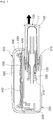
- FIG. 3 is a cross-sectional view of the cosmetic container according to one embodiment of the present invention.
- the cosmetic container may include an inner container 100 which stores contents, a container body 200, a discharge means 300, a distributor 400, and an upper cap 500.
- the inner container 100 is a container storing contents, is insertable into the container body 200 through an open portion 210 formed in the container body 200, and is separable from the container body 200 through the open portion 210.
- insertion may mean the inner container 100 being led in into the container body 200 through the open portion 210 formed in the container body 200 or the inner container 100 being coupled with the container body 200 or another component of the container body 200, for example, the discharge means 300 after entering therein.
- separation means the inner container 100 being released from the container body 200 and may include a state of the inner container 100 being removed from the container body 200 through the open portion 210 formed in the container body 200 or a state of the inner container 100 being movable while being partially inserted into the open portion 210.
- FIG. 4 is a view illustrating the inner container 100 of the cosmetic container according to one embodiment of the present invention.
- components of the inner container 100 will be described with reference to FIG. 4 .
- the inner container 100 may include a storage portion 110, in which contents are stored, and an outer circumferential portion 120 formed to protrude from at least one surface of the storage portion.
- the outer circumferential portion 120 may be formed to have a greater width than that of the storage portion while surrounding the at least one surface of the storage portion and may protrude outward from the storage portion 110.
- the outer circumferential portion 120 may form one surface of the container body 200 so as to smoothly connect the inner container 100 and the container body 200 to each other.
- the cosmetic container may be manufactured to have an external shape which includes fluid curves overall and provides smooth aesthetics according to a user's taste.
- the inner container 100 may include a shoulder 130 having an upper outer surface in contact with an intermediate body 410 and a lower outer surface in contact with the container body 200 so as to be stably slidable into the container body 200 during an insertion process and to remain stable in the container body 200 after insertion.
- a fluid contained in the inner container 100 may be a cosmetic fluid.
- the fluid contained in the inner container 100 may include cosmetic materials for color make-up such as a liquid type foundation or cosmetic materials for skin care such as a gel type suncream but is not limited thereto and may include all types of fluid-state cosmetic materials.
- cosmetic materials for color make-up such as a liquid type foundation or cosmetic materials for skin care such as a gel type suncream but is not limited thereto and may include all types of fluid-state cosmetic materials.
- powder-type cosmetic materials or solid cosmetic materials may be contained in the inner container 100.
- cosmetic materials including one or more of a fluid, powder, and solid may be contained in the inner container 100.
- the inner container 100 may be formed of a film 111 or may include the film 111 in the storage portion 110.
- the film 111 may contain a fluid therein.
- the film 111 may be a material which is compressed and deformable according to a discharge of a fluid.
- the film 111 may have a multilayer formation of several thin sheets.
- an inside thereof may be a vacuum.
- the film 111 since the film 111 is compressed as a fluid is discharged, it is possible to use an entirety of a fluid in the storage portion 110 without residual contents. Also, it is possible to maintain a quality of and sanitary use of cosmetic materials by preventing problems such as deterioration, dryness, exposure, and the like caused by an air inflow when the cosmetic container is used.
- the open portion 210 is formed in one side of the container body 200, and the inner container 100 may be inserted into the container body 200 through the open portion 210. In some embodiments, the inner container 100 may slide and be inserted into the container body 200 in a sliding manner.
- the open portion 210 into which the inner container 100 is inserted may be formed in a side surface of the container body 200. Also, the open portion 210 may be formed in one or more side surfaces. For example, open portions 210 into which the inner container 100 is inserted may be formed in one or more of the side surfaces of the container body 200 of the cosmetic container. The open portion 210 into which the inner container 100 is inserted may be formed in any one among other surfaces excluding a side surface on which the button portion 230 formed at the container body 200 to open or close the upper cap 500 is mounted and a side surface on which a connecting portion connecting the upper cap 500 to the container body 200 is mounted.
- the open portion 210 into which the inner container 100 is inserted may be formed in a bottom surface of the container body 200.
- the inner container 100 may move from a bottom end to a top end to be inserted into the container body 200 through the open portion 210 formed in the bottom surface of the container body 200 and then may discharge contents therein while moving vertically or may be separated from the container body 200 while moving to the bottom end.
- the open portion 210 into which the inner container 100 is inserted may have a greater breadth than a width of the storage portion 110 of the inner container 100. Also, according to one embodiment, the open portion 210 may have a width greater than or equal to a breadth of the outer circumferential portion 120 of the inner container 100.
- FIG. 5 is a bottom perspective view illustrating a bottom surface of the cosmetic container according to one embodiment of the present invention. Hereinafter, a description will be given with reference to FIG. 5 .
- a grip portion 220 is a component for easily inserting, removing, and/or pressurizing the inner container 100 and may be formed in the container body 200 or the inner container 100.
- the grip portion 220 may be formed to have a groove or protrusion shape or may be formed as a space between containers.
- a user may apply a pressure for inserting or pressurizing to the inner container 100 more easily by gripping the grip portion 220 when the inner container 100 is inserted or pressurized. For example, when it is necessary to separate the inner container 100 from the container body 200, the user inserts a finger into the grip portion 220 and pushes the inner container 100 toward an outside of the container body 200 so as to easily separate the inner container 100.
- the grip portion 220 may be formed in a space between the open portion 210 of the container body 200 and the outer circumferential portion 120 of the inner container.
- a space is formed between the open portion 210 and the outer circumferential portion 120 of the inner container when the inner container 100 is inserted into the open portion 210. The user may utilize the space as the grip portion 220.
- the grip portion 220 may be formed at the bottom end of the container body 200. Also, the grip portion 220 may be formed in a space between a bottom end of the inner container 100 coupled with the container body 200 and the bottom end of the container body 200.
- the user may separate the inner container 100 from the container body 200 more easily by inserting a finger into the grip portion 220 formed at the bottom end of the container body 200 while gripping the cosmetic container with one hand.
- the container body 200 may include the button portion 230 on one side thereof, which is operated to open or close the upper cap 500.
- the button portion 230 may be formed on a side opposite to a side on which the connecting portion between the upper cap 500 and the container body 200 is disposed but is not limited thereto and may be located in any part of the container body 200.
- the button portion 230 may operate in a manner of being pressurized toward the inside of the cosmetic container or a manner of sliding in both directions along an outer circumferential part of the cosmetic container or in a vertical direction.
- the discharge means 300 may include a pump 310, a pump nozzle 320, and an elastic member 330.
- the pump 310 discharges contents accommodated in the inner container and may include a cylinder and a piston.
- the pump 310 may be an airless pump or a dip-tube type pump.
- the storage portion 110 of the inner container 100 may include a movable film or a movable piston moved within the storage portion 110 of the inner container 100 as a volume of a fluid is reduced by discharge.
- the storage portion 110 of the inner container 100 may be implemented as a pouch shape which contracts as a volume of a fluid is reduced by discharging contents.
- the pump nozzle 320 is coupled with the pump 310 and delivers contents to the distributor 400.
- the pump nozzle 320 may be fastened to the container body 200 or the distributor 400 (particularly, the intermediate body 410) coupled with the container body 200 so as to be indirectly coupled with the container body 200.
- the elastic member 330 pushes the inner container 100 out in a direction opposite to a pressurizing direction.
- the elastic member 330 may return the pressurized inner container 100 to an original position thereof before being pressurized or may move the inner container 100 to a position in which the inner container 100 is removed more easily.
- the elastic member 330 may be coupled with an outer surface of the pump 310.
- the elastic member 330 may be a spring but is not limited to the above example.
- the discharge means 300 may be coupled with the inner container 100 and may be coupled with the container body 200. Also, a part of the discharge means 300 may be formed in the inner container 100 or another part thereof may be formed in the container body 200 or the distributor 400.
- the pump 310 may be formed in the inner container 100, the pump nozzle 320 may be formed in the distributor 400, and the pump 310 may be coupled with the pump nozzle 320 when the inner container 100 is inserted into the container body 200.
- the pump 310 and the elastic member 330 may be formed in the inner container 100 and the pump nozzle 320 may be formed in the distributor 400.
- Arrangements of the pump 310, the pump nozzle 320, and the elastic member 330 are not limited to the above embodiments and may be formed diversely.
- the discharge means 300 may further include a backflow prevention member for preventing a backflow of a pumped fluid.
- the backflow prevention member may be further disposed in the cylinder inside the pump 310.
- a position of the backflow prevention member with respect to the discharge means 300 is not limited and there is no limit in materials of the backflow prevention member. Due to the backflow prevention member, a fluid passing through the discharge means 300 may flow in only one direction.
- the distributor 400 is a component which distributes contents discharged by the discharge means and may include the intermediate body 410, distributing plates 420 and 430, and a fixing cap 450.
- the intermediate body 410 may be coupled with the discharge means 300 and may transfer contents discharged by the discharge means 300 to the distributing plates 420 and 430.
- the intermediate body 410 may include a flow path 411 configured to transfer contents to the distributing plates 420 and 430.
- a fluid discharged from the inner container 100 by pressurizing of the inner container 100 may sequentially flow through the pump nozzle 320 and the flow path 411 of the intermediate body 410 to be supplied to the distributing plates 420 and 430.
- the intermediate body 410 may be fastened to the container body 200 through a fastening member provided below the intermediate body 410.
- An upper part of the intermediate body 410 may be fastened to the distributing plates 420 and 430 and the fixing cap 450 and a lower part thereof may be fastened to the container body 200.
- the intermediate body 410 may be integrally formed with the distributing plates 420 and 430 or the fixing cap 450. Also, some or all of the intermediate body 410, the distributing plates 420 and 430, and the fixing cap 450 may be integrally formed.
- the distributing plates 420 and 430 may distribute a fluid discharged by the inner container 100 coupled with the container body 200.
- the distributing plates 420 and 430 include an upper distributing plate 430 and a lower distributing plate 420.
- the lower distributing plate 420 may include at least one hole for transferring a fluid to the upper distributing plate 430.
- the hole of the lower distributing plate 420 may be one hole formed in a center of the lower distributing plate 420.
- the upper distributing plate 430 may include a distribution path 431 so as to distribute contents discharged by the discharge means 300.
- the distribution path 431 may include a plurality of holes, grooves, and/or incised parts.
- the distribution path 431 may be formed and disposed to uniformly distribute a fluid induced through the hole of the lower distributing plate 420.
- the distribution path 431 may be formed to have a radial shape, a circular shape, or the like and to have an image capable of forming an aesthetic or a pattern such as a letter and a logo which are recognizable by the user.
- a shape of the distribution path 431 is not limited to the embodiment and may have a variety of shapes.
- the upper distributing plate 430 may be formed of a hard material such that a shape thereof is not deformed by a pressure applied by a cosmetic tool such as a puff and the like.
- the upper distributing plate 430 may be formed of materials such as a metal, ceramic, synthetic resin, and the like.
- the fixing cap 450 performs a function of fixing the distributing plates 420 and 430 and may fix the distributing plates 420 and 430 to the container body 200 by being fastened to the intermediate body 410 while being disposed on the upper distributing plate 430 and a top end of the lower distributing plate 420.
- the fixing cap 450 may include an annular rib which protrudes upward to prevent a fluid distributed by the distributing plates 420 and 430 from flowing outside the distributing plates 420 and 430.
- the upper distributing plate 430, the lower distributing plate 420, and the fixing cap 450 may be separately formed or some or an entirety thereof may be integrally formed. Some components may be omitted.
- a fluid accommodated in the inner container 100 flows toward the pump nozzle 320 through the pump 310 and subsequently flows along the flow path 411 of the intermediate body 410 to be induced into the upper distributing plate 430 through the hole formed in the lower distributing plate 420.
- the induced fluid may be uniformly distributed on a surface of the upper distributing plate 430 while passing through the distribution path 431.
- the user may uniformly apply the fluid uniformly distributed on the surface of the upper distributing plate 430 to the face, body, or the like by using a cosmetic tool such as a puff and the like.
- the distributor 400 may further include a mesh 440.
- the mesh 440 may be a flexible mesh including a plurality of micro holes.
- the mesh 440 may include a single mesh or a plurality of meshes.
- the mesh may be manufactured using polyethylene (PE) materials or may include the same but is not limited thereto and may be manufactured using a variety of materials or may include the same.
- PE polyethylene
- the mesh 440 may uniformly distribute cosmetic materials all over an entire surface of the mesh 440.
- the mesh 440 may be disposed above the upper distributing plate 430 and may prevent the discharged cosmetic materials from flying from the upper distributing plate 430. Also, when contents are extracted by pressurizing the upper distributing plate 430 using a cosmetic tool such as a puff, it is necessary to allow an adequate amount of contents to be applied to the cosmetic tool.
- the cosmetic container may further include a dipping member instead of the distributing plates 420 and 430 or with the distributing plates 420 and 430.
- the dipping member may be filled with cosmetic materials induced into the distributing plates 420 and 430 or the intermediate body 410.
- the dipping member may be formed of a porous material such as a sponge and may uniformly distribute cosmetic materials throughout an entirety of a capacity of the dipping member.
- the cosmetic container may further include an accommodating member capable of accommodating a cosmetic tool such as a puff.
- the accommodating member may be disposed on the upper distributing plate 430.
- the accommodating member may be formed for a cosmetic tool to be separated from the upper distributing plate 430 so as to not come into contact therewith.
- the accommodating member may be formed to be connected to a part of the cosmetic container and be movable in a hinge manner.
- the upper cap 500 performs a function of sealing the container body 200.
- the upper cap 500 may be connected to the container body 200 through a connecting portion such as a hinge formed on one side.
- the connecting portion may be configured to prevent the upper cap 500 from being separated from the container body 200 when the upper cap 500 is disposed in an open position.
- the upper cap 500 may be connected to the intermediate body 410 through a connecting portion such as a hinge formed on one side.
- the upper cap 500 may be directly coupled with the container body 200 without the connecting portion.
- the upper cap 500 and the container body 200 may include a screw thread formed thereinside to be coupled with each other through mutual rotation.
- the cosmetic container may include a holding portion 510 configured to prevent the inner container 100 coupled with the container body 200 from being pressurized against the inside of the container body 200 while the upper cap 500 is closed.
- the holding portion 510 may be formed on the upper cap 500.
- the holding portion 510 may be formed to protrude toward a bottom end of the upper cap 500 to be engaged with the top end of the coupled inner container 100.
- a shape of the holding portion 510 is not limited to the embodiment and may have a variety of shapes.
- one or more holding portions 510 may be formed along a circumferential part of the upper cap 500 or may be arranged to be spaced apart.
- the holding portion 510 may be formed to protrude from a vicinity of a coupling place of the inner container 100 to come into contact with a part of the inner container 100 and prevent the inner container 100 from being pressurized against the inside of the container body 200.
- the holding portion 510 may be formed on the inner container 100.
- the inner container 100 coupled with the container body 200 is restrained by the holding portion 510, which is formed on the inner container 100, from moving into the container body 200.
- the holding portion 510 may be formed corresponding to a direction in which the inner container is inserted. For example, when the inner container 100 is inserted through a left side surface of the container body 200, the holding portion 510 may be formed on a left side surface of the cosmetic container. When the inner container 100 is inserted through a right side surface of the container body 200, the holding portion 510 may be formed on a right side surface of the cosmetic container. When the inner container 100 is inserted through a front or rear surface of the container body 200, the holding portion 510 may be formed on a front or rear surface of the cosmetic container.
- a mirror 520 may be attached to an inner surface of the upper cap 500.
- the user may check his or her own appearance in the mirror 520 and may apply a fluid distributed from the cosmetic container to the face, body, or the like.
- the mirror 520 may be formed of glass but is not limited thereto and may be manufactured using other materials or may include a variety of materials.
- a shape of the mirror 520 may be a circular shape or a quadrangular shape but is not limited to the above examples.
- the mirror 520 may also be detachably attached to the upper cap 500.
- the upper cap 500 may include a fastening portion 530 with, for example, a hook-shaped end on one side.
- a hook of the upper cap 500 is engaged with a recess in a concave part formed at a top end of the button portion 230 provided on the container body 200 such that the upper cap 500 remains in a closed position.
- the hook of the upper cap 500 is released from the recess of the button portion 230 such that the upper cap 500 may be movable to an opened position.
- the hook type fastening portion 530 may be formed in the button portion 230 and a concave portion having a recess to be engaged with the hook-shaped holding portion may be formed in the upper cap 500.
- the present invention is not limited to the compact container and is applicable to a variety of cosmetic containers.
- the present invention is applicable not only to cosmetic products but also to the fields of medications, foods, and the like.
- FIG. 6 is a view illustrating a state in which the inner container of the cosmetic container is pressurized against the inside of the container body according to one embodiment of the present invention
- FIG. 7 is a view illustrating a state in which the inner container of the cosmetic container is separated from the container body according to one embodiment of the present invention.
- the inner container 100 may be inserted into the container body 200 and then be pressurized against the inside of the container body 200.
- the holding portion 510 is formed on the upper cap 500 such that the upper cap 500 seals the container body 200
- the holding portion 510 comes into contact with a part of the inner container 100 such that the inner container 100 inserted in the container body may be prevented from being pressurized against the inside of the container body 200. That is, the inner container 100 is not pressurized against the inside of the container body 200 while the upper cap 500 is closed such that it is possible to prevent contents from being discharged due to a malfunction.
- the piston When the upper cap 500 is opened and the inner container 100 is pressurized against the inside of the container body 200, the piston may be inserted into the cylinder connected to storage portion 110 in the inner container 100 to perform fluid communication such that a fluid in the inner container 100 may flow through the piston and the pump nozzle 320 and be discharged through the distributor 400.
- the fluid accommodated in the inner container 100 flows toward the pump nozzle 320 through the pump 310 and subsequently flows along the flow path 411 of the intermediate body 410 to be discharged into the upper distributing plate 430 through the hole formed in the lower distributing plate 420.
- the discharged fluid may be uniformly distributed on the surface of the upper distributing plate 430 while passing through the distribution path 431.
- the user may apply the fluid uniformly distributed on the surface of the upper distributing plate 430 uniformly to the face, body, or the like by using a cosmetic tool such as a puff and the like.
- the inner container 100 pressurized by the elastic member 330 returns to an original position thereof before being pressurized.
- the user may continuously discharge contents by pressurizing the inner container 100 against the inside of the container body 200 again as necessary.
- a user of the cosmetic container according to one embodiment of the present invention may insert or remove the inner container 100 into or from the container body 200 while gripping the cosmetic container with one hand.
- a user who uses the cosmetic container according to one embodiment of the present invention in FIG. 1 , may grip the cosmetic container with one hand, open the upper cap 500, and then discharge contents by pressurizing the inner container 100 on the side surface of the cosmetic container against the inside of the container body 200 using a thumb.
- the inner container 100 may be separated from the container body 200 by inserting a finger into the grip portion 220 formed in a space between the open portion 210 of the container body 200 and the outer circumferential portion 120 of the inner container.
- the user may insert, remove, or replace the inner container 100 into or from the container body 200 using only one hand more easily instead of using both hands.
Landscapes
- Engineering & Computer Science (AREA)
- Mechanical Engineering (AREA)
- Containers And Packaging Bodies Having A Special Means To Remove Contents (AREA)
- Closures For Containers (AREA)
- Packages (AREA)
- Cosmetics (AREA)
Applications Claiming Priority (2)
| Application Number | Priority Date | Filing Date | Title |
|---|---|---|---|
| KR1020180093684A KR102065015B1 (ko) | 2018-08-10 | 2018-08-10 | 리필 가능한 내용기를 포함하는 화장품 용기 |
| PCT/KR2019/004898 WO2020032346A1 (ko) | 2018-08-10 | 2019-04-23 | 리필 가능한 내용기를 포함하는 화장품 용기 |
Publications (3)
| Publication Number | Publication Date |
|---|---|
| EP3689181A1 true EP3689181A1 (de) | 2020-08-05 |
| EP3689181A4 EP3689181A4 (de) | 2020-10-28 |
| EP3689181B1 EP3689181B1 (de) | 2023-06-28 |
Family
ID=69158476
Family Applications (1)
| Application Number | Title | Priority Date | Filing Date |
|---|---|---|---|
| EP19798148.3A Active EP3689181B1 (de) | 2018-08-10 | 2019-04-23 | Kosmetikbehälter mit nachfüllbarem innenbehälter |
Country Status (7)
| Country | Link |
|---|---|
| US (1) | US11241073B2 (de) |
| EP (1) | EP3689181B1 (de) |
| JP (1) | JP6848090B2 (de) |
| KR (1) | KR102065015B1 (de) |
| CN (1) | CN111031845B (de) |
| ES (1) | ES2953319T3 (de) |
| WO (1) | WO2020032346A1 (de) |
Families Citing this family (5)
| Publication number | Priority date | Publication date | Assignee | Title |
|---|---|---|---|---|
| USD957262S1 (en) * | 2018-10-30 | 2022-07-12 | Berlin Packaging, Llc | Bottle having dual configuration |
| USD1055392S1 (en) * | 2021-10-04 | 2024-12-24 | Shiseido Company, Limited | Powder compact |
| USD1072613S1 (en) * | 2022-06-21 | 2025-04-29 | Yonwoo Co., Ltd. | Compact container |
| JP1754193S (ja) * | 2022-07-27 | 2023-09-29 | 化粧用コンパクト | |
| US20240358136A1 (en) * | 2023-04-28 | 2024-10-31 | Elc Management Llc | Cosmetic delivery system |
Family Cites Families (18)
| Publication number | Priority date | Publication date | Assignee | Title |
|---|---|---|---|---|
| US3987935A (en) | 1975-11-17 | 1976-10-26 | The Raymond Lee Organization, Inc. | Perfume dispenser |
| KR100518193B1 (ko) * | 2004-09-23 | 2005-09-30 | 주식회사 케미코스크리에이션즈코리아 | 액체 화장료용 도포구 |
| GB2439306A (en) | 2006-06-21 | 2007-12-27 | Natalie Harris | A handcleaning dispenser system |
| KR200450028Y1 (ko) * | 2008-03-26 | 2010-09-01 | 주식회사 리치코스 | 콤팩트 용기 |
| CN201243725Y (zh) | 2008-04-23 | 2009-05-27 | 深圳市裕鼎精密工业科技股份有限公司 | 化妆品盒 |
| KR200457811Y1 (ko) * | 2009-08-07 | 2012-01-05 | 강성일 | 액상 내용물을 분말상의 화장료를 향해 분무시키는 화장품 용기 |
| KR101231786B1 (ko) * | 2011-03-14 | 2013-02-08 | (주)톨리코리아 | 에어리스 펌프를 가지는 화장품용기의 내용물 토출장치 |
| KR101252115B1 (ko) | 2011-10-12 | 2013-04-12 | (주)연우 | 리필이 가능한 펌핑식 앰플용기 |
| JP5947124B2 (ja) | 2012-06-27 | 2016-07-06 | 紀伊産業株式会社 | 化粧料容器 |
| KR101527758B1 (ko) * | 2013-08-06 | 2015-06-12 | (주)연우 | 에어리스 콤팩트 용기 |
| KR101906821B1 (ko) * | 2014-02-14 | 2018-10-15 | 주식회사 엘지생활건강 | 화장품 용기 |
| KR200482745Y1 (ko) | 2015-01-23 | 2017-03-31 | 펌텍코리아 (주) | 블로우 용기를 구비한 측면 가압 콤팩트 용기 |
| KR200483953Y1 (ko) | 2015-01-27 | 2017-07-13 | 펌텍코리아 (주) | 파우치 용기를 구비한 측면 가압 콤팩트 용기 |
| KR101552900B1 (ko) * | 2015-03-31 | 2015-09-16 | 민병선 | 화장품용기 |
| WO2017004673A1 (en) | 2015-07-06 | 2017-01-12 | Mitchell Terrace Pty. Ltd. | Device for applying a product |
| KR20180004340A (ko) * | 2016-06-27 | 2018-01-11 | 펌텍코리아 (주) | 혼합쿠션과 혼합메쉬망이 구비된 콤팩트 용기 |
| FR3059213B1 (fr) | 2016-11-25 | 2019-07-12 | Sebastien Fauconnier | Dispositif de distribution experientiel d'un produit cosmetique |
| KR102000014B1 (ko) * | 2019-04-02 | 2019-07-17 | (주)연우 | 화장품 용기 |
-
2018
- 2018-08-10 KR KR1020180093684A patent/KR102065015B1/ko active Active
-
2019
- 2019-04-23 ES ES19798148T patent/ES2953319T3/es active Active
- 2019-04-23 EP EP19798148.3A patent/EP3689181B1/de active Active
- 2019-04-23 US US16/604,234 patent/US11241073B2/en active Active
- 2019-04-23 CN CN201980002031.1A patent/CN111031845B/zh active Active
- 2019-04-23 JP JP2019556309A patent/JP6848090B2/ja active Active
- 2019-04-23 WO PCT/KR2019/004898 patent/WO2020032346A1/ko not_active Ceased
Also Published As
| Publication number | Publication date |
|---|---|
| ES2953319T3 (es) | 2023-11-10 |
| JP2020529223A (ja) | 2020-10-08 |
| US11241073B2 (en) | 2022-02-08 |
| CN111031845A (zh) | 2020-04-17 |
| CN111031845B (zh) | 2022-03-25 |
| EP3689181B1 (de) | 2023-06-28 |
| KR102065015B1 (ko) | 2020-01-10 |
| JP6848090B2 (ja) | 2021-03-24 |
| WO2020032346A1 (ko) | 2020-02-13 |
| EP3689181A4 (de) | 2020-10-28 |
| US20200383453A1 (en) | 2020-12-10 |
Similar Documents
| Publication | Publication Date | Title |
|---|---|---|
| EP3689181B1 (de) | Kosmetikbehälter mit nachfüllbarem innenbehälter | |
| US5261570A (en) | Flexible liquid dispenser | |
| EP3078295B1 (de) | Kosmetikbehälter mit lösbar an der seite eines knopfelements befestigtem auftragselement | |
| US10398211B2 (en) | Bottle cap with cosmetic kit | |
| JP6845866B2 (ja) | 液状製品、特にクリーム等の化粧用液状製品の圧縮可能なディスペンサ | |
| US20130221037A1 (en) | Container for liquid | |
| CN208553141U (zh) | 设置有袋容器的垂直按压式粉盒容器 | |
| US20130058698A1 (en) | Applicator for fluid products | |
| KR200459837Y1 (ko) | 화장품 용기 | |
| CN110213977A (zh) | 用于化妆品制品的可再装填的包装装置 | |
| KR20010086210A (ko) | 유체 도포기 | |
| KR101392980B1 (ko) | 퍼프를 가지는 화장품용기의 내용물 토출장치 | |
| EP3305126B1 (de) | Kompakter behälter mit horizontal an die seite einer pumpe gekoppeltem inhaltsvorratsbehälter | |
| US20220048056A1 (en) | Liquid dispenser | |
| US20050226678A1 (en) | Eyeglass cleaner | |
| US20190069979A1 (en) | Toothbrush | |
| US20200329843A1 (en) | Refill for liquid makeup case and assembly comprising a case and such a refill | |
| KR102310817B1 (ko) | 내용물 용기 | |
| EP3200644B1 (de) | Flaschenverschluss mit kosmetischem kit | |
| CN209031377U (zh) | 内容物容器 | |
| KR102833283B1 (ko) | 액체 토출형 미용도구 | |
| CN114727695B (zh) | 容器 | |
| WO2007072040A1 (en) | Depilatory cream dispenser | |
| US20230134733A1 (en) | Systems, methods, and apparatuses for implementing a self-contained cosmetic applicator kit | |
| KR101900086B1 (ko) | 화장품 충진 장치 및 이를 포함하는 화장품 제작 세트 |
Legal Events
| Date | Code | Title | Description |
|---|---|---|---|
| STAA | Information on the status of an ep patent application or granted ep patent |
Free format text: STATUS: UNKNOWN |
|
| STAA | Information on the status of an ep patent application or granted ep patent |
Free format text: STATUS: THE INTERNATIONAL PUBLICATION HAS BEEN MADE |
|
| PUAI | Public reference made under article 153(3) epc to a published international application that has entered the european phase |
Free format text: ORIGINAL CODE: 0009012 |
|
| STAA | Information on the status of an ep patent application or granted ep patent |
Free format text: STATUS: REQUEST FOR EXAMINATION WAS MADE |
|
| 17P | Request for examination filed |
Effective date: 20191213 |
|
| AK | Designated contracting states |
Kind code of ref document: A1 Designated state(s): AL AT BE BG CH CY CZ DE DK EE ES FI FR GB GR HR HU IE IS IT LI LT LU LV MC MK MT NL NO PL PT RO RS SE SI SK SM TR |
|
| AX | Request for extension of the european patent |
Extension state: BA ME |
|
| RIN1 | Information on inventor provided before grant (corrected) |
Inventor name: JUNG, SEO HUI Inventor name: KIM, YU SEOB |
|
| A4 | Supplementary search report drawn up and despatched |
Effective date: 20200930 |
|
| RIC1 | Information provided on ipc code assigned before grant |
Ipc: A45D 33/20 20060101ALI20200924BHEP Ipc: B65D 25/02 20060101ALI20200924BHEP Ipc: A45D 34/04 20060101ALI20200924BHEP Ipc: A45D 34/00 20060101ALI20200924BHEP Ipc: A45D 40/26 20060101AFI20200924BHEP Ipc: B05C 11/10 20060101ALI20200924BHEP Ipc: A45D 40/14 20060101ALI20200924BHEP Ipc: A45D 33/00 20060101ALI20200924BHEP Ipc: A45D 40/22 20060101ALI20200924BHEP Ipc: B65D 83/00 20060101ALI20200924BHEP Ipc: A45D 40/00 20060101ALI20200924BHEP Ipc: A45D 40/16 20060101ALI20200924BHEP |
|
| STAA | Information on the status of an ep patent application or granted ep patent |
Free format text: STATUS: EXAMINATION IS IN PROGRESS |
|
| 17Q | First examination report despatched |
Effective date: 20210709 |
|
| DAV | Request for validation of the european patent (deleted) | ||
| DAX | Request for extension of the european patent (deleted) | ||
| GRAP | Despatch of communication of intention to grant a patent |
Free format text: ORIGINAL CODE: EPIDOSNIGR1 |
|
| STAA | Information on the status of an ep patent application or granted ep patent |
Free format text: STATUS: GRANT OF PATENT IS INTENDED |
|
| INTG | Intention to grant announced |
Effective date: 20230329 |
|
| GRAS | Grant fee paid |
Free format text: ORIGINAL CODE: EPIDOSNIGR3 |
|
| GRAA | (expected) grant |
Free format text: ORIGINAL CODE: 0009210 |
|
| STAA | Information on the status of an ep patent application or granted ep patent |
Free format text: STATUS: THE PATENT HAS BEEN GRANTED |
|
| AK | Designated contracting states |
Kind code of ref document: B1 Designated state(s): AL AT BE BG CH CY CZ DE DK EE ES FI FR GB GR HR HU IE IS IT LI LT LU LV MC MK MT NL NO PL PT RO RS SE SI SK SM TR |
|
| REG | Reference to a national code |
Ref country code: CH Ref legal event code: EP |
|
| REG | Reference to a national code |
Ref country code: AT Ref legal event code: REF Ref document number: 1581928 Country of ref document: AT Kind code of ref document: T Effective date: 20230715 |
|
| REG | Reference to a national code |
Ref country code: IE Ref legal event code: FG4D |
|
| REG | Reference to a national code |
Ref country code: DE Ref legal event code: R096 Ref document number: 602019031828 Country of ref document: DE |
|
| REG | Reference to a national code |
Ref country code: LT Ref legal event code: MG9D |
|
| PG25 | Lapsed in a contracting state [announced via postgrant information from national office to epo] |
Ref country code: SE Free format text: LAPSE BECAUSE OF FAILURE TO SUBMIT A TRANSLATION OF THE DESCRIPTION OR TO PAY THE FEE WITHIN THE PRESCRIBED TIME-LIMIT Effective date: 20230628 Ref country code: NO Free format text: LAPSE BECAUSE OF FAILURE TO SUBMIT A TRANSLATION OF THE DESCRIPTION OR TO PAY THE FEE WITHIN THE PRESCRIBED TIME-LIMIT Effective date: 20230928 |
|
| REG | Reference to a national code |
Ref country code: NL Ref legal event code: MP Effective date: 20230628 |
|
| REG | Reference to a national code |
Ref country code: ES Ref legal event code: FG2A Ref document number: 2953319 Country of ref document: ES Kind code of ref document: T3 Effective date: 20231110 |
|
| REG | Reference to a national code |
Ref country code: AT Ref legal event code: MK05 Ref document number: 1581928 Country of ref document: AT Kind code of ref document: T Effective date: 20230628 |
|
| PG25 | Lapsed in a contracting state [announced via postgrant information from national office to epo] |
Ref country code: RS Free format text: LAPSE BECAUSE OF FAILURE TO SUBMIT A TRANSLATION OF THE DESCRIPTION OR TO PAY THE FEE WITHIN THE PRESCRIBED TIME-LIMIT Effective date: 20230628 Ref country code: NL Free format text: LAPSE BECAUSE OF FAILURE TO SUBMIT A TRANSLATION OF THE DESCRIPTION OR TO PAY THE FEE WITHIN THE PRESCRIBED TIME-LIMIT Effective date: 20230628 Ref country code: LV Free format text: LAPSE BECAUSE OF FAILURE TO SUBMIT A TRANSLATION OF THE DESCRIPTION OR TO PAY THE FEE WITHIN THE PRESCRIBED TIME-LIMIT Effective date: 20230628 Ref country code: LT Free format text: LAPSE BECAUSE OF FAILURE TO SUBMIT A TRANSLATION OF THE DESCRIPTION OR TO PAY THE FEE WITHIN THE PRESCRIBED TIME-LIMIT Effective date: 20230628 Ref country code: HR Free format text: LAPSE BECAUSE OF FAILURE TO SUBMIT A TRANSLATION OF THE DESCRIPTION OR TO PAY THE FEE WITHIN THE PRESCRIBED TIME-LIMIT Effective date: 20230628 Ref country code: GR Free format text: LAPSE BECAUSE OF FAILURE TO SUBMIT A TRANSLATION OF THE DESCRIPTION OR TO PAY THE FEE WITHIN THE PRESCRIBED TIME-LIMIT Effective date: 20230929 |
|
| PG25 | Lapsed in a contracting state [announced via postgrant information from national office to epo] |
Ref country code: FI Free format text: LAPSE BECAUSE OF FAILURE TO SUBMIT A TRANSLATION OF THE DESCRIPTION OR TO PAY THE FEE WITHIN THE PRESCRIBED TIME-LIMIT Effective date: 20230628 |
|
| PG25 | Lapsed in a contracting state [announced via postgrant information from national office to epo] |
Ref country code: SK Free format text: LAPSE BECAUSE OF FAILURE TO SUBMIT A TRANSLATION OF THE DESCRIPTION OR TO PAY THE FEE WITHIN THE PRESCRIBED TIME-LIMIT Effective date: 20230628 |
|
| PG25 | Lapsed in a contracting state [announced via postgrant information from national office to epo] |
Ref country code: IS Free format text: LAPSE BECAUSE OF FAILURE TO SUBMIT A TRANSLATION OF THE DESCRIPTION OR TO PAY THE FEE WITHIN THE PRESCRIBED TIME-LIMIT Effective date: 20231028 |
|
| PG25 | Lapsed in a contracting state [announced via postgrant information from national office to epo] |
Ref country code: SM Free format text: LAPSE BECAUSE OF FAILURE TO SUBMIT A TRANSLATION OF THE DESCRIPTION OR TO PAY THE FEE WITHIN THE PRESCRIBED TIME-LIMIT Effective date: 20230628 Ref country code: SK Free format text: LAPSE BECAUSE OF FAILURE TO SUBMIT A TRANSLATION OF THE DESCRIPTION OR TO PAY THE FEE WITHIN THE PRESCRIBED TIME-LIMIT Effective date: 20230628 Ref country code: RO Free format text: LAPSE BECAUSE OF FAILURE TO SUBMIT A TRANSLATION OF THE DESCRIPTION OR TO PAY THE FEE WITHIN THE PRESCRIBED TIME-LIMIT Effective date: 20230628 Ref country code: PT Free format text: LAPSE BECAUSE OF FAILURE TO SUBMIT A TRANSLATION OF THE DESCRIPTION OR TO PAY THE FEE WITHIN THE PRESCRIBED TIME-LIMIT Effective date: 20231030 Ref country code: IS Free format text: LAPSE BECAUSE OF FAILURE TO SUBMIT A TRANSLATION OF THE DESCRIPTION OR TO PAY THE FEE WITHIN THE PRESCRIBED TIME-LIMIT Effective date: 20231028 Ref country code: EE Free format text: LAPSE BECAUSE OF FAILURE TO SUBMIT A TRANSLATION OF THE DESCRIPTION OR TO PAY THE FEE WITHIN THE PRESCRIBED TIME-LIMIT Effective date: 20230628 Ref country code: CZ Free format text: LAPSE BECAUSE OF FAILURE TO SUBMIT A TRANSLATION OF THE DESCRIPTION OR TO PAY THE FEE WITHIN THE PRESCRIBED TIME-LIMIT Effective date: 20230628 Ref country code: AT Free format text: LAPSE BECAUSE OF FAILURE TO SUBMIT A TRANSLATION OF THE DESCRIPTION OR TO PAY THE FEE WITHIN THE PRESCRIBED TIME-LIMIT Effective date: 20230628 |
|
| PG25 | Lapsed in a contracting state [announced via postgrant information from national office to epo] |
Ref country code: PL Free format text: LAPSE BECAUSE OF FAILURE TO SUBMIT A TRANSLATION OF THE DESCRIPTION OR TO PAY THE FEE WITHIN THE PRESCRIBED TIME-LIMIT Effective date: 20230628 |
|
| REG | Reference to a national code |
Ref country code: DE Ref legal event code: R097 Ref document number: 602019031828 Country of ref document: DE |
|
| PG25 | Lapsed in a contracting state [announced via postgrant information from national office to epo] |
Ref country code: DK Free format text: LAPSE BECAUSE OF FAILURE TO SUBMIT A TRANSLATION OF THE DESCRIPTION OR TO PAY THE FEE WITHIN THE PRESCRIBED TIME-LIMIT Effective date: 20230628 |
|
| PLBE | No opposition filed within time limit |
Free format text: ORIGINAL CODE: 0009261 |
|
| STAA | Information on the status of an ep patent application or granted ep patent |
Free format text: STATUS: NO OPPOSITION FILED WITHIN TIME LIMIT |
|
| 26N | No opposition filed |
Effective date: 20240402 |
|
| PG25 | Lapsed in a contracting state [announced via postgrant information from national office to epo] |
Ref country code: SI Free format text: LAPSE BECAUSE OF FAILURE TO SUBMIT A TRANSLATION OF THE DESCRIPTION OR TO PAY THE FEE WITHIN THE PRESCRIBED TIME-LIMIT Effective date: 20230628 |
|
| PG25 | Lapsed in a contracting state [announced via postgrant information from national office to epo] |
Ref country code: BG Free format text: LAPSE BECAUSE OF FAILURE TO SUBMIT A TRANSLATION OF THE DESCRIPTION OR TO PAY THE FEE WITHIN THE PRESCRIBED TIME-LIMIT Effective date: 20230628 |
|
| PG25 | Lapsed in a contracting state [announced via postgrant information from national office to epo] |
Ref country code: MC Free format text: LAPSE BECAUSE OF FAILURE TO SUBMIT A TRANSLATION OF THE DESCRIPTION OR TO PAY THE FEE WITHIN THE PRESCRIBED TIME-LIMIT Effective date: 20230628 |
|
| PG25 | Lapsed in a contracting state [announced via postgrant information from national office to epo] |
Ref country code: MC Free format text: LAPSE BECAUSE OF FAILURE TO SUBMIT A TRANSLATION OF THE DESCRIPTION OR TO PAY THE FEE WITHIN THE PRESCRIBED TIME-LIMIT Effective date: 20230628 Ref country code: BG Free format text: LAPSE BECAUSE OF FAILURE TO SUBMIT A TRANSLATION OF THE DESCRIPTION OR TO PAY THE FEE WITHIN THE PRESCRIBED TIME-LIMIT Effective date: 20230628 |
|
| PG25 | Lapsed in a contracting state [announced via postgrant information from national office to epo] |
Ref country code: LU Free format text: LAPSE BECAUSE OF NON-PAYMENT OF DUE FEES Effective date: 20240423 |
|
| REG | Reference to a national code |
Ref country code: BE Ref legal event code: MM Effective date: 20240430 |
|
| PG25 | Lapsed in a contracting state [announced via postgrant information from national office to epo] |
Ref country code: LU Free format text: LAPSE BECAUSE OF NON-PAYMENT OF DUE FEES Effective date: 20240423 |
|
| PG25 | Lapsed in a contracting state [announced via postgrant information from national office to epo] |
Ref country code: BE Free format text: LAPSE BECAUSE OF NON-PAYMENT OF DUE FEES Effective date: 20240430 |
|
| PG25 | Lapsed in a contracting state [announced via postgrant information from national office to epo] |
Ref country code: BE Free format text: LAPSE BECAUSE OF NON-PAYMENT OF DUE FEES Effective date: 20240430 |
|
| PG25 | Lapsed in a contracting state [announced via postgrant information from national office to epo] |
Ref country code: IE Free format text: LAPSE BECAUSE OF NON-PAYMENT OF DUE FEES Effective date: 20240423 |
|
| PGFP | Annual fee paid to national office [announced via postgrant information from national office to epo] |
Ref country code: FR Payment date: 20250321 Year of fee payment: 7 |
|
| PGFP | Annual fee paid to national office [announced via postgrant information from national office to epo] |
Ref country code: GB Payment date: 20250313 Year of fee payment: 7 |
|
| PGFP | Annual fee paid to national office [announced via postgrant information from national office to epo] |
Ref country code: DE Payment date: 20250311 Year of fee payment: 7 |
|
| PGFP | Annual fee paid to national office [announced via postgrant information from national office to epo] |
Ref country code: ES Payment date: 20250508 Year of fee payment: 7 |
|
| PGFP | Annual fee paid to national office [announced via postgrant information from national office to epo] |
Ref country code: IT Payment date: 20250326 Year of fee payment: 7 |
|
| PGFP | Annual fee paid to national office [announced via postgrant information from national office to epo] |
Ref country code: CH Payment date: 20250501 Year of fee payment: 7 |
|
| PG25 | Lapsed in a contracting state [announced via postgrant information from national office to epo] |
Ref country code: CY Free format text: LAPSE BECAUSE OF FAILURE TO SUBMIT A TRANSLATION OF THE DESCRIPTION OR TO PAY THE FEE WITHIN THE PRESCRIBED TIME-LIMIT; INVALID AB INITIO Effective date: 20190423 |
|
| PG25 | Lapsed in a contracting state [announced via postgrant information from national office to epo] |
Ref country code: HU Free format text: LAPSE BECAUSE OF FAILURE TO SUBMIT A TRANSLATION OF THE DESCRIPTION OR TO PAY THE FEE WITHIN THE PRESCRIBED TIME-LIMIT; INVALID AB INITIO Effective date: 20190423 |