EP3688232B1 - Plug and abandonment of one or more offshore platform wellbores of an offshore platform using a marine jack-up type vessel - Google Patents
Plug and abandonment of one or more offshore platform wellbores of an offshore platform using a marine jack-up type vessel Download PDFInfo
- Publication number
- EP3688232B1 EP3688232B1 EP18827270.2A EP18827270A EP3688232B1 EP 3688232 B1 EP3688232 B1 EP 3688232B1 EP 18827270 A EP18827270 A EP 18827270A EP 3688232 B1 EP3688232 B1 EP 3688232B1
- Authority
- EP
- European Patent Office
- Prior art keywords
- cantilever
- hull
- vessel
- jack
- deck
- Prior art date
- Legal status (The legal status is an assumption and is not a legal conclusion. Google has not performed a legal analysis and makes no representation as to the accuracy of the status listed.)
- Active
Links
- 230000000694 effects Effects 0.000 claims description 46
- 238000005553 drilling Methods 0.000 claims description 29
- 238000000034 method Methods 0.000 claims description 28
- 230000003028 elevating effect Effects 0.000 claims description 16
- XLYOFNOQVPJJNP-UHFFFAOYSA-N water Substances O XLYOFNOQVPJJNP-UHFFFAOYSA-N 0.000 claims description 15
- 238000013461 design Methods 0.000 claims description 7
- 239000004606 Fillers/Extenders Substances 0.000 description 27
- 238000003032 molecular docking Methods 0.000 description 22
- 238000003860 storage Methods 0.000 description 12
- 230000004308 accommodation Effects 0.000 description 10
- 230000000712 assembly Effects 0.000 description 6
- 238000000429 assembly Methods 0.000 description 6
- 230000005484 gravity Effects 0.000 description 6
- 238000013459 approach Methods 0.000 description 5
- 238000004904 shortening Methods 0.000 description 4
- 230000009286 beneficial effect Effects 0.000 description 3
- 229930195733 hydrocarbon Natural products 0.000 description 3
- 150000002430 hydrocarbons Chemical class 0.000 description 3
- 230000008901 benefit Effects 0.000 description 2
- 238000005520 cutting process Methods 0.000 description 2
- 238000010304 firing Methods 0.000 description 2
- 238000009434 installation Methods 0.000 description 2
- 238000012423 maintenance Methods 0.000 description 2
- 239000004215 Carbon black (E152) Substances 0.000 description 1
- 229910000831 Steel Inorganic materials 0.000 description 1
- 229910000746 Structural steel Inorganic materials 0.000 description 1
- 238000004873 anchoring Methods 0.000 description 1
- 238000005452 bending Methods 0.000 description 1
- 238000006073 displacement reaction Methods 0.000 description 1
- 230000009977 dual effect Effects 0.000 description 1
- 238000007667 floating Methods 0.000 description 1
- NJPPVKZQTLUDBO-UHFFFAOYSA-N novaluron Chemical compound C1=C(Cl)C(OC(F)(F)C(OC(F)(F)F)F)=CC=C1NC(=O)NC(=O)C1=C(F)C=CC=C1F NJPPVKZQTLUDBO-UHFFFAOYSA-N 0.000 description 1
- 238000000926 separation method Methods 0.000 description 1
- 239000010959 steel Substances 0.000 description 1
- 238000005728 strengthening Methods 0.000 description 1
- 238000012546 transfer Methods 0.000 description 1
Images


Classifications
-
- E—FIXED CONSTRUCTIONS
- E02—HYDRAULIC ENGINEERING; FOUNDATIONS; SOIL SHIFTING
- E02B—HYDRAULIC ENGINEERING
- E02B17/00—Artificial islands mounted on piles or like supports, e.g. platforms on raisable legs or offshore constructions; Construction methods therefor
- E02B17/02—Artificial islands mounted on piles or like supports, e.g. platforms on raisable legs or offshore constructions; Construction methods therefor placed by lowering the supporting construction to the bottom, e.g. with subsequent fixing thereto
- E02B17/021—Artificial islands mounted on piles or like supports, e.g. platforms on raisable legs or offshore constructions; Construction methods therefor placed by lowering the supporting construction to the bottom, e.g. with subsequent fixing thereto with relative movement between supporting construction and platform
-
- E—FIXED CONSTRUCTIONS
- E02—HYDRAULIC ENGINEERING; FOUNDATIONS; SOIL SHIFTING
- E02B—HYDRAULIC ENGINEERING
- E02B17/00—Artificial islands mounted on piles or like supports, e.g. platforms on raisable legs or offshore constructions; Construction methods therefor
- E02B2017/0052—Removal or dismantling of offshore structures from their offshore location
Definitions
- the present invention relates to the field of decommissioning of offshore platforms and the associated subsea wellbores.
- decommission is required at the end of life of a subsea hydrocarbon field.
- International and national legislation exist that mandates decommissioning. For example some legislation demands a full removal of platforms in less than 100 meters water depth, whereas in deeper water a part of the jacket may remain on the seabed.
- the decommissioning further often involves the (partial) removal of flowlines, mattresses, piling, etc.
- P&A plug and abandonment
- WO2012/144952 discloses a marine jack-up vessel for decommissioning an offshore platform. Parts of the topside, referred to as superstructure, are moved to the jack-up or a supply vessel. This is carried out by the crane at the cantilever. In the process of 'top sides removal' scraped parts that are placed in containers and moved to the deck using the crane. The containers are ultimately transported to supply ships for disposal using pedestal cranes.
- the marine jack-up vessel of WO2017/142938 is provided with a cantilever comprising a crane.
- the cantilever is extended from the marine jack-up vessel to allow the crane, which is on top of the cantilever, to move components of the offshore platform to a transport vessel or to the deck of the marine jack-up vessel depending on the deck load capacity.
- the present invention aims to propose measures that allow for a more efficient and economical decommissioning of offshore platforms.
- the invention proposes a method for permanent plug and abandonment according to claim 1.
- this method obviates the need to use a separate dedicated heavy lift crane vessel to lift the topsides from the jacket and to transport the topside to a remote location, e.g. to a shore based disposal site or an offshore location where the topsides is transferred onto another vessel for transport to an onshore disposal site.
- the advantage of the invention is not merely that a heavy lift crane vessel is not needed for at least the removal of the topsides, so avoiding costs incurred by use of such a crane vessel. Also time is saved as even the task of properly anchoring and positioning such a crane vessel near the platform is time consuming as live producing flowlines may be present on the seabed and in view of the often reduced structural integrity of the platform. This activity is now avoided as the jack-up type vessel is used also for the removal of the topsides. It is noted for completeness that between the steps of performing plug and abandonment and lifting the topsides, according to the invention, the marine jack-up type vessel is not displaced or moved.
- the inventive approach also avoids the use of a barge to place the topsides thereon once lifted from the jacket as is often done in conjunction with the use of a heavy lift crane vessel in the prior art approach to decommissioning. This avoids any issues related to the potential that such a barge might collide with one or more legs of the jack-up type vessel that is still in its jacked-up operative position.
- the applicability of the method of the invention is limited by the hoisting capacity of the one or more cranes of the marine jack-up type vessel that are capable or configured, in view of location onboard the vessel and hoisting capabilities, to serve in the process of lifting and handling the topsides.
- each crane of the vessel is capable, in view of location onboard the vessel and hoisting capabilities, to serve in the process of lifting and handling the topsides.
- a crane has a lifting capacity of at least 600 tonnes (600.000 kg) at a reach or radius of 20 meters from the slew axis, e.g. a capacity of about 1000 tonnes (1.000.000 kg) at said reach or radius of 20 meters from the slew axis.
- the vessel has, at the cantilever deployment side of the hull, two cranes capable or configured, in view of location onboard the vessel and hoisting capabilities, to serve in the process of lifting and handling the topsides, preferably two the same cranes.
- said one or more cranes has a reach beyond said cantilever deployment side and over a portion of said main deck.
- each crane of the vessel involved in the lifting and handling of the topsides is a leg encircling crane having a slew bearing extending about a respective jack-up leg of the vessel. It is conceivable that a topside has a weight of 800 tonnes (800.000 kg), in particular over 1000 tonnes (1.000.000 kg), or possibly even over 1300 tonnes (1.300.000 kg).
- each crane of the vessel involved in the lifting and handling of the topsides is fixed to the hull in proximity of a jack-up leg of the vessel, e.g. on a foot that is structurally combined with a housing for the respective elevating unit for the jack-up leg.
- the offshore platform comprises a jacket and a topsides.
- jacket not only encompasses the common design of a platform substructure as a structural steel framework, but also other seabed mounted substructures, like concrete substructures.
- topsides may be separated into parts that are handled in multiple lifts. The latter is e.g. less preferred in view of costs associated with the separation but may be needed in case the structure of the topsides has become too weak to lift the topsides as a unit.
- the cantilever is movable to a retracted position to allow the lowering of the vessel in order to make the vessel buoyant again.
- the cantilever is not just retracted to allow for the later lifting of the topsides, but the cantilever is moved into a deck clearing position wherein an area of the deck is cleared and the topsides is landed by the one or more cranes on said clear deck area.
- innovative embodiments of a marine jack-up type vessel that provide such deck clearing capabilities are discussed herein below as said vessel may also be applicable to other methods and even distinct fields of use, e.g. offshore wellbore drilling activities, e.g. for hydrocarbons but also for CO 2 storage, etc., thermal energy well drilling, offshore wellbore intervention and/or workover activities to be performed on existing wellbores, or even offshore wind farm installation and/or maintenance activities, etc..
- the cantilever motion assembly is not only adapted to move the cantilever relative to the hull between a retracted position and extended positions wherein the operational end of the cantilever structure extends beyond one of said sides of the hull, but also to move the cantilever into said deck clearing position so that sufficient area of the deck is cleared to receive at least the topsides thereon.
- the method of the invention comprises the step of operating the cantilever motion assembly to move the cantilever into said deck clearing position.
- the one or more cranes of the vessel are employed to lift the cantilever, e.g. once returned into the retracted position, and move said cantilever into the deck clearing position to clear sufficient deck space for the topsides.
- the cantilever is used as support of the removed topsides and that the topsides is placed by means of the one or more cranes of the vessel onto the cantilever, preferably said cantilever then being in its retracted position when the topsides is placed thereon.
- decommissioning generally also requires the removal of the jacket on which the topsides is supported, e.g. as a whole, in parts, or just an upper part with a lower part remaining on the seabed.
- the one or more cranes of the jack-up type vessel are also employed for the, at least partial, removal of the jacket.
- the one or more cranes involved in the lifting of the jacket have a maximum operative height in said lifting process of the crane hook above the design waterline of the buoyant hull that exceeds 55 meters, preferably exceeds 75 meters, e.g. between 75 and 110 meters.
- the lifted jacket or part thereof is also placed onboard the vessel, e.g. on the main deck.
- the jacket or part thereof remains suspended from the one or more cranes as the vessel is sailed away from the site of the decommissioned platform.
- a barge or other transport vessel is brought into, onto which the jacket or part thereof is transferred, preferably said transfer taking place once the jack-up vessel has been lowered so as to become buoyant again, thereby avoiding issues related to the potential of collision between the barge and the legs.
- the method may comprise - after removal of the topsides, the step of lowering an internal cutting tool into a leg of the jacket and operating said cutting tool to cut the leg, e.g. the steel leg, preferably in proximity of the seabed, possibly some distance below the seabed.
- the lowering of such a tool may for example be done using one of the cranes of the vessel.
- one or more buoyancy modules are connected to the jacket or part thereof, e.g. the modules having clamps that secure the module onto a leg of the platform, prior to lifting by means of the one or more cranes of the vessel, e.g. to reduce the load on the cranes and so expand the capability of the vessel to deal with heavier jackets.
- the jacket is lifted by the one or more cranes of the vessel and then disposed of on the seabed, e.g. tilted horizontally, at the same or another site to serve as the basis for an artificial reef.
- the latter approach may e.g. be envisaged for sites in the Gulf of Mexico.
- a marine jack-up type vessel that is envisaged as beneficial for use in the method of the invention may also be of benefit for other applications, other methods and even distinct fields of use, e.g. offshore wellbore drilling activities, e.g. for hydrocarbons but also for CO 2 storage, etc., thermal energy well drilling, offshore wellbore intervention and/or workover activities to be performed on existing wellbores, or even offshore wind farm installation and/or maintenance activities, etc..
- offshore wellbore drilling activities e.g. for hydrocarbons but also for CO 2 storage, etc.
- thermal energy well drilling e.g. for offshore wellbore intervention and/or workover activities to be performed on existing wellbores, or even offshore wind farm installation and/or maintenance activities, etc.
- Such a more versatile marine jack-up type vessel e.g. allowing a more efficient and economical decommissioning of offshore platforms, comprises:
- the cantilever motion assembly and/or the crane is adapted to move the cantilever into a deck clearing position wherein a deck area of the main deck is cleared to form a clear deck area.
- the clear deck area of the main deck is present between said cantilever and the cantilever deployment side, and measures at least 20 meters in a direction perpendicular to said cantilever deployment side and at least 10 meters transverse to said direction.
- the clear deck area measures at least 25 x 25 meters.
- the clear deck area e.g. allows for placing a topsides on said clear deck area according to the method of the invention, using said crane.
- the cantilever motion assembly is adapted to move the cantilever relative to the hull at least in longitudinal direction thereof.
- the cantilever is adapted to move also in a transverse direction, e.g. as disclosed in US6729804 of the same applicant, or wherein the cantilever is rotatable, e.g. as disclosed in US2004151549 , or alternatively as disclosed in EP2823105 of the same applicant.
- the crane advantageously has a reach beyond said cantilever deployment side and over a portion of said main deck, in particular over the clear deck area between the cantilever and the cantilever deployment side.
- the cantilever motion assembly comprises one or more rails mounted on said main deck, e.g. in a axial direction of the hull perpendicular to the second axial side. Said one or more rails extend towards or to a side of the hull opposite the cantilever deployment side, so as to allow for the cantilever motion assembly to move the cantilever relative to the vessel at least in said longitudinal direction thereof, between extended positions wherein the operational end of the cantilever structure extends beyond the cantilever deployment side of the hull, and a retracted position.
- said operational end of the cantilever structure is positioned above the hull, before the sides of the hull and the entire cantilever is within the contour of the hull.
- the cantilever being within a contour delimited by said jack-up legs.
- the cantilever in said deck clearing position is positioned further towards a side of the hull then said retracted position.
- a clear deck area of the main deck is present between said cantilever and the cantilever deployment side, for example a clear deck area of at least 20 meters in a direction perpendicular to said cantilever deployment side and at least 10 meters transverse to said direction, e.g. to allow for placing a topsides on said clear deck area according to the method of the invention, using said crane.
- the vessel has an axially extending docking space, e.g. an open ended axially extending docking space, that is present between a first superstructure, e.g. accommodation superstructure, of the vessel at the first lateral side of the vessel, proximate a first axial end, and a second superstructure, e.g. accommodation superstructure, of the vessel at the second lateral side of the vessel, proximate said first axial end, allowing to receive therein at least a part of the cantilever when in said deck clearing position thereof.
- a third superstructure extends above the docking space, bridging the first and second superstructure. This third superstructure e.g. comprises a helicopter landing space.
- the inner end of the cantilever structure is forked, formed by transversely spaced first and second cantilever inner end extension parts.
- said first and second cantilever inner end extension parts are mobile relative to the cantilever structure when in said deck clearing position thereof, e.g. foldable about a vertical axis, or removable from the cantilever structure so as to reduce the length of the cantilever, allowing to move the cantilever further away from the cantilever deployment side than in said retracted position and into said deck clearing position.
- the cantilever structure has a reducable length with a reduced length when in said deck clearing position thereof, so as to reduce the length of the cantilever, allowing to move the cantilever further away from the cantilever deployment side than in said retracted position and into said deck clearing position.
- Examples of how the length of the cantilever structure can be reduced is by providing foldable or removable parts of the cantilever structure, or by providing a telescopic structure of the cantilever.
- the cantilever motion assembly and/or the crane is adapted to move the cantilever into a deck clearing position wherein a clear deck area of the main deck is present between said cantilever and the cantilever deployment side of at least 20 meters in a direction perpendicular to said cantilever deployment side and at least 10 meters transverse to said direction, e.g. to allow for placing a topsides on said clear deck area according to the method of any of claims 1 - 6 using said crane.
- Such a marine jack-up type vessel allows wellbore activities wherein use is made of the cantilever in the extended position.
- the vessel provides a clear deck area of at least 20x10 metres in the deck clearing position of the cantilever. This clear deck area can e.g. be used for placing a topsides, but other purposes are also conceivable.
- a marine jack-up type vessel comprising
- Such a marine jack-up type vessel allows wellbore activities wherein use is made of the cantilever in the extended position.
- the vessel provides a clear deck area in the deck clearing position of the cantilever. This clear deck area can e.g. be used for placing a topsides, but other purposes are also conceivable.
- Such a vessel covers alternative deck clearing positions of the cantilever.
- the operational end of the cantilever structure extends beyond a cantilever deployment side of said sides of the hull.
- the cantilever deployment side is the second axial side.
- the operational end is retracted to a position above deck, no longer extending beyond the deployment side of the hull.
- the cantilever is moved into a deck clearing position wherein a deck area of the main deck is cleared.
- this is achieved by moving the cantilever to a position wherein the inner end of the cantilever structure extends beyond said first axial side of the hull of the vessel. Hence, from extending beyond the second axial end, the cantilever is allowed to move to a position extending beyond the first axial end. In this position, the inner end of the cantilever structure extends beyond the hull, the operation end is preferably still positioned above the hull.
- this is achieved by moving the cantilever to a position wherein the operational end of the cantilever structure is arranged between the legs of the first pair of jack-up legs, and the rest of the cantilever extends towards and possibly beyond the first axial side of the hull. In this position, the deck area between the first pair of jack-up legs and the second axial side of the hull is cleared. The inner end of the cantilever structure may still be positioned above the hull, or extend beyond the first axial side of the hull.
- this is achieved by moving the cantilever to a position wherein the centre of gravity of the cantilever is arranged, in side view, beyond the first pair of jack-up legs relative to the second pair of jack-up legs, preferably between the first pair of jack-up legs and the first axial side of the hull or.
- the centre of gravity of the cantilever is located relatively close to this operational end.
- the docking space is an open ended axially extending docking space, that is present between a first superstructure, e.g. accommodation superstructure, of the vessel at the first lateral side of the vessel, proximate the first axial end, and a second superstructure, e.g. accommodation superstructure, of the vessel at the second lateral side of the vessel, proximate said first axial end.
- a third superstructure extends above the docking space, bridging the first and second superstructure. This third superstructure e.g. comprises a helicopter landing space.
- said crane is a first leg encircling crane comprising:
- said vessel further comprises a second leg encircling crane comprising a foot fixed to the hull, a slew bearing supported on the foot and extending about the other jack-up leg of the second pair of jack-up legs of the vessel, a slewable crane member which is supported by said slew bearing, and a boom pivotally mounted to said slewable crane member about a horizontal boom pivot axis so that the boom is pivotal up and down.
- a second leg encircling crane comprising a foot fixed to the hull, a slew bearing supported on the foot and extending about the other jack-up leg of the second pair of jack-up legs of the vessel, a slewable crane member which is supported by said slew bearing, and a boom pivotally mounted to said slewable crane member about a horizontal boom pivot axis so that the boom is pivotal up and down.
- the cantilever motion assembly comprises one or more rails mounted on said main deck, e.g. in a axial direction of the hull perpendicular to the second axial side. Said one or more rails extend towards or to the first axial side of the hull so as to allow for the cantilever motion assembly to move the cantilever relative to the vessel at least in said longitudinal direction between extended positions wherein the operational end of the cantilever structure extends beyond the second axial side of the hull and a retracted position wherein said operational end is before the second axial side of the hull and the entire cantilever is within the contour of the hull, e.g. the cantilever being within a contour delimited by said jack-up legs.
- the cantilever in said deck clearing position is positioned further towards the first axial side then said retracted position wherein a clear deck area of the main deck is present between said cantilever and said second axial side, for example a clear deck area of at least 20 meters in a direction perpendicular to said cantilever deployment side and at least 10 meters transverse to said direction, e.g. to allow for placing a topsides on said clear deck area according to the invention using said crane.
- the vessel has an axially extending docking space, e.g. an open ended axially extending docking space, that is present between a first superstructure, e.g. accommodation superstructure, of the vessel at the first lateral side of the vessel, proximate the first axial end, and a second superstructure, e.g. accommodation superstructure, of the vessel at the second lateral side of the vessel, proximate said first axial end, allowing to receive therein at least a part of the cantilever when in said deck clearing position thereof.
- a first superstructure e.g. accommodation superstructure
- second superstructure e.g. accommodation superstructure
- a three jack-up legs marine jack-up type vessel comprising:
- Such a vessel covers alternative deck clearing positions of the cantilever on a three jack-up leg marine jack-up type vessel.
- the operational end of the cantilever structure extends beyond a cantilever deployment side of said sides of the hull.
- the cantilever deployment side is the side opposite said single jack-up leg closest to said first apex.
- the operational end Upon retraction in the longitudinal direction thereof the operational end is retracted to a position above deck, no longer extending beyond the deployment side of the hull.
- the cantilever is moved into a deck clearing position wherein a deck area of the main deck is cleared.
- a deck area of the main deck is cleared between said cantilever and said cantilever deployment side, for example a clear deck area of at least 20 meters in a direction perpendicular to said cantilever deployment side and at least 10 meters transverse to said direction, e.g. to allow for placing a topsides on said clear deck area according to the method of the invention using said crane.
- the inner end of the cantilever structure is forked, formed by transversely spaced first and second cantilever inner end extension parts.
- clearing of the main deck is possibly achieved by moving the cantilever into a deck clearing position wherein said first and second cantilever inner end extension parts are received on transversely opposite locations relative to said single jack-up leg closest to a first apex of said triangular hull on said longitudinal axis thereof.
- said first and second cantilever inner end extension parts are mobile relative to the cantilever structure when in said retracted position thereof, e.g. foldable about a vertical axis, or removable from the cantilever structure so as to reduce the length of the cantilever.
- clearing of the main deck is possibly achieved by allowing to move the cantilever further towards said first apex than in said retracted position and into said deck clearing position.
- the cantilever system that is used in combination with the invention described herein may be embodied as disclosed in WO2013/133694 , e.g. in order to have an envelope for the wellbore activities station that allows to treat a grid of wellbores on an offshore platform, e.g. a two-dimensional grid of wellbores as is known in the art.
- the wellbore activities station may be movable relative to the cantilever, e.g. movable transverse relative to the cantilever structure, to achieve a suitable envelope, e.g. the cantilever structure merely being movable in its longitudinal direction relative to the hull.
- the invention may make use of a marine jack-up type vessel, e.g. as disclosed in WO2013/133694 , comprising:
- the invention makes use of a marine jack-up type vessel, e.g. as disclosed in WO2013/133694 , comprising:
- the cantilever inner end carrier device is disconnectable from said one or more cantilever structure extender members for the purpose of said removal or motion into said storage position of said one or more cantilever structure extender members.
- a cantilever system comprising an elongated cantilever structure with a longitudinal axis and with an operational end, wherein said operational end supports a wellbore activities station, e.g. a drilling station, or is adapted to support a wellbore activities station thereon, e.g. a mobile drilling station, said cantilever structure having an inner end longitudinally opposite the operational end,
- the cantilever system may have a rigid operational end module which has opposed lateral side walls, and the cantilever structure preferably comprises two folding cantilever structure extender members, that are each hinged about a vertical axis relative to an inner end of a respective lateral side wall of the rigid operational end module so as to each be pivotal between a longitudinally extended position wherein each folding cantilever structure extender member extends generally in line with the respective side wall of the rigid operational end module, and a folded position wherein each folding cantilever structure extender member generally is located alongside the respective side wall of the rigid operational end module, and wherein said cantilever inner end carrier device is disconnectable from said cantilever structure extender members for the purpose of said folding into said storage position of said cantilever structure extender members.
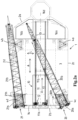
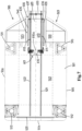
- a marine jack-up type vessel 1 is shown, suitable for performing the method according to the invention.
- the vessel 1 has been arranged adjacent an offshore platform 50, comprising a topsides 51 and a jacket 52.
- the offshore platform is provide above one or more offshore platform wellbores 55, provided at the bottom of the sea B.
- the water level W of the sea is also indicated, as well as the waterline WW of the buoyant hull of the vessel, when the vessel is afloat.
- the marine jack-up type vessel 1 comprises a buoyant hull 2 with a main deck 3, said hull having sides.
- the buoyant hull 2 has an axial direction A and a first axial side 2a, and a second axial side 2b.
- the hull 2 has a lateral direction L, and a first lateral side 2c and a second lateral side 2d.
- the vessel has at least three jack-up legs.
- the vessel 1 comprises a first pair of jack-up legs 4a, 4b which are spaced apart in said transverse direction from one another.
- a second pair of jack-up legs 4c, 4d are also spaced apart in said transverse direction from one another. Said first and second pairs are spaced from one another in said axial direction A.
- the first pair of jack-up legs 4a, 4b being closest to the first axial side 2a of the hull 2 and the second pair of jack-up legs 4c, 4d being closest to the second axial side 2b of the hull 2.
- the vessel further comprises a plurality of elevating units, not shown in detail, each associated with a respective jack-up leg, adapted to move the respective jack-up leg 4a, 4b, 4c, 4d vertically relative to the hull 2 and to bring the vessel in an operational position wherein the legs engage the seabed and the hull is above water level.
- the elevating units have been operated and brought the vessel 1 in an operational position wherein the vessel is not afloat but wherein the jack-up legs 4a, 4b, 4c, 4d engage the seabed B.
- the feet of the jack-up legs are partly buried in the bottom of the sea B.
- the hull 2 is above water level W at a height such that a cantilever 10 is movable in an extended position above the topsides 51 of the offshore platform 50.
- the vessel further comprises a cantilever 10 having a cantilever structure 11 with an operational end 11a, wherein said operational end supports a wellbore activities station 12, e.g. a drilling station, or is adapted to support a wellbore activities station thereon, e.g. a mobile drilling station, said cantilever structure 11 having an inner end 11b longitudinally opposite the operational end 11a, wherein the cantilever is movably mounted on the main deck 3 of the hull.
- a wellbore activities station 12 e.g. a drilling station
- a wellbore activities station e.g. a drilling station
- a wellbore activities station e.g. a mobile drilling station
- a cantilever motion assembly 13 is provided and adapted to move the cantilever relative to the hull 3 at least in longitudinal direction CL thereof between a retracted position and extended positions wherein the operational end 11a of the cantilever extends beyond a cantilever deployment side of said sides of the hull.
- the cantilever deployment side of the hull is the second axial side 2b.
- the cantilever motion assembly has moved the cantilever 10 into an extended position wherein the operational end 11a of the cantilever extends beyond the cantilever deployment side 2, and above the topsides 51.
- the wellbore activities station 12 is aligned with a wellbore 55 of the offshore platform 50.
- This configuration of fig. 1 allows the performance of wellbore activities such as drilling and plug and abandonment operations, involving the use of the wellbore activities station.
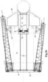
- the cantilever 10 is shown in a retracted position. In the shown position, the operational end 11a of the cantilever no longer extends beyond the hull of the vessel.
- the cantilever motion assembly comprises two parallel rails 13, mounted on the main deck 3 allowing movement of the cantilever 10.
- the rails 13 are mounted in an axial direction A of the hull, perpendicular to the second axial side 2b, and extend in the longitudinal direction CL of the cantilever.
- Said one or more rails 13 extend towards or to the first axial side 2a of the hull so as to allow for the cantilever motion assembly to move the cantilever 10 relative to the vessel at least in said longitudinal direction CL between extended positions wherein the operational end 11a of the cantilever extends beyond the second axial side 2b of the hull, a retracted position wherein said operational end 11a is before the second axial side of the hull 2b and the entire cantilever 10 is within the contour of the hull, e.g. the cantilever being within a contour delimited by said jack-up legs.
- a rail 14 is mounted on said main deck 3 in the lateral direction L of the hull, parallel to and adjacent the second axial side, allowing a lateral movement of the cantilever between multiple extended positions.
- Two cranes 20, 21 are fixed to the hull and having a boom 20b, 21b that is slewable about a vertical slew axis 20s, 21s and pivotal up and down about a horizontal boom pivot axis 20h, 21h.
- crane 20 is a first leg encircling crane comprising a foot 20f fixed to the hull, a slew bearing supported on the foot and extending about a jack-up leg 4c of the second pair of jack-up legs of the vessel, a slewable crane member 20sb which is supported by said slew bearing, a boom 20b pivotally mounted to said slewable crane member 20sb about a horizontal boom pivot axis 20h so that the boom is pivotal up and down.
- the slewable crane member 20sb comprises a protruding superstructure 20c.
- crane 21 is a second leg encircling crane comprising a foot fixed to the hull, a slew bearing supported on the foot and extending about the other jack-up leg 4d of the second pair of jack-up legs of the vessel, a slewable crane member which is supported by said slew bearing, a boom 21b pivotally mounted to said slewable crane member about a horizontal boom pivot axis 21h so that the boom is pivotal up and down.
- the cantilever 10 has moved into a deck clearing position wherein a deck area of the main deck is cleared to form a clear deck area 3C between said cantilever 10 and said second axial side 2b.
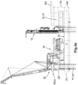
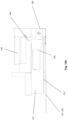
- Fig. 3a is a side view of the operational situation of fig. 2b , with the cantilever 10 in the deck clearing position.
- the clear deck area 3C measures at least 20 meters in a direction perpendicular to said cantilever deployment side 2b, here the axial direction A of the vessel, and at least 10 meters transverse to said direction, here the longitudinal direction L of the vessel, e.g. to allow for placing a topsides on said clear deck area according to the method of the invention using said cranes 20, 21.
- the inner end 11b of the cantilever structure extends to, but not yet beyond said first axial side 2a of the hull of the vessel. It is also conceivable that the inner end 11b does extend beyond this first axial side 2a.
- the operational end 11a of the cantilever structure 11 is arranged between the legs of the first pair of jack-up legs 4a, 4b, and the rest of the cantilever extends towards the first axial side 2a of the hull.
- the centre of gravity G of the cantilever is arranged, in side view, between or beyond the first pair of jack-up legs 4a, 4b (shown is beyond).
- the centre of gravity G of the cantilever is arranged, in side view, beyond the first pair of jack-up legs 4a, 4b, relative to the second pair of jack-up legs 4c, 4d, preferably between the first pair of jack-up legs 4a, 4b and the first axial side 2a of the hull.
- the axially extending docking space 15 is e.g. an open ended axially extending docking space, that is present between a first superstructure 16a, e.g. accommodation superstructure, of the vessel at the first lateral side 2c of the vessel, proximate the first axial end 2a, and a second superstructure 16b, e.g. accommodation superstructure, of the vessel at a second lateral side 2d of the vessel, proximate said first axial end 2a.
- a third superstructure 16c extends above the docking space 15, bridging the first and second superstructure 16a, 16b.
- This third superstructure e.g. comprises a helicopter landing space 16d.
- topsides 51 has been disconnected from the jacket 52, and the topsides 51 is being lifted from the jacket 52 by means of the cranes 20, 21 of the vessel.
- an entire topsides 51 is lifted in a single-lift by means of the cranes 20, 51 of the jack-up type vessel.
- fig. 3b In the detailed view of fig. 3b , it is indicated in striped lines LL how close the jack-up vessel 1 can be positioned adjacent the offshore platform 50. This allows both wellbore operations involving the use of the wellbore activities station 12 on the cantilever 10, as well as lifting operations of the cranes 20, 21.
- fig. 3c the detail of the offshore platform 50 is shown in a top view.
- a different type of offshore platform 150 is shown in a side view and top view respectively.
- striped lines LL indicate how close the jack-up vessel 1 can be positioned adjacent the offshore platform 150, both for wellbore operations and for lifting operations, e.g. involving the removal of the topsides.
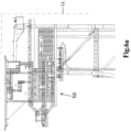
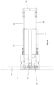
- a side view and top view respectively of a marine jack-up type vessel 1 is shown with the topsides 51 placed on board the vessel by means of said crane 20, 21.
- the topsides 51 is positioned on the clear deck area 3C created by a retracted cantilever, here in the deck clearing position of the cantilever 10.
- the topsides 51 positioned above the rails 13 of the cantilever motion assembly. It is also conceivable and within the scope of the invention that the topsides is positioned on board the vessel at any available deck area, e.g. on top of a (part of the) cantilever.
- the situation of figs. 4a and 4b is possibly followed by operating the elevating units so as to lower the hull of the vessel into the sea and to retract the jack-up legs upward. With the vessel 1 afloat, the topsides 51 can be brought to any desired location.
- the situation of figs. 4a and 4b is followed by lifting the jacket 52, as shown in fig. 5 .
- the one or more cranes 20, 21 of the jack-up type vessel are also employed for the, at least partial, removal of the jacket 52.
- this jacket 52 is also positioned on board the vessel 1, or alternatively on board another vessel or barge.
- the cantilever system may be readily combined with any marine jack-up type vessel comprising:
- the cantilever could also be mounted on the main deck of some other vessel, e.g. a floating vessel, e.g. a semi-submersible vessel, a monohull vessel lacking jack-up capability, etc.
- a floating vessel e.g. a semi-submersible vessel, a monohull vessel lacking jack-up capability, etc.
- inventive cantilever system is here shown in combination with a four legged marine jack-up vessel, but the system may for example also be combined with a three legs jack-up vessel.
- Figure 7 and figure 13 show in plan view the vessel 500 having a buoyant hull 501 with a main deck 502.
- the hull 501 has a first axial side 503, a second axial side, also called cantilever deployment side 504, and lateral sides 505, 506.
- the vessel 500 has a first pair of jack-up legs 510, 511 closest to the first axial side 503, with the legs 510, 511 being spaced in transverse direction of the hull.
- the vessel 500 has a second pair of jack-up legs 512, 513 closest to the cantilever deployment side 504, the legs 512, 513 also be spaced in transverse direction of the hull.
- a leg encircling crane is provide around one or each of the jack-up legs 512, 513 near the deployment side 504 of the hull, e.g. in view of the lifting and handling of a topsides as discussed herein.
- the vessel 500 may be a six legged vessel, with an intermediate or third pair of jack-up legs located centrally between the first and second pairs of legs.
- a four legged vessel 500 is preferred in view of costs, handling, etc.
- elevating units e.g. with a rackand-pinion or a hydraulic stepping mechanism.
- Each elevating unit is associated with a respective jack-up leg and is adapted to move the respective jack-up leg vertically relative to the hull and to bring the vessel in an operational position wherein the legs engage the seabed and the hull is above water level.
- Such elevating units may be housed in respective housings or frames on the main deck and/or recessed in the hull of the vessel.
- the jack-up legs are latticed jack-up legs, here of a triangular cross-section.
- the hull 501 has a longitudinal axis, here parallel to the lateral sides 505, 506 of the hull.
- At least a first support rail 520 for a cantilever system extends along the cantilever deployment side 504 of the hull, e.g. over the main deck 502 of the vessel 500.
- one or more, herein a pair of, second support rails 521, 522 extend over the main deck 502 in a direction perpendicular to the first support rail 520, here in longitudinal direction of the hull.
- the second support rails 521, 522 extend, as preferred, from an end thereof proximate the first support rail 520 and/or the cantilever deployment side 504 of the hull, to an end thereof that lies beyond the first pair of jack-up legs 510, 511, e.g. to an end in proximity of the first axial side 503 of the hull.
- the vessel is provided with a first superstructure 530 and a second superstructure 535 at the first lateral side 503 of the vessel, so at the port and starboard corner region of the hull at said side, here between the respective leg of the first pair of legs and said first axial side.
- These superstructures 530, 535 may for example be embodied as housing for crew members, work spaces, bridge, control rooms, storage of tools and supplies, etc.
- the superstructures 530, 535 at said first axial side 503 are laterally spaced apart, at least in a region thereof in line with the main deck 502 and over a height to accommodate therein a part of the cantilever of the vessel in a deck clearing position thereof. So the lateral spacing between the superstructures 530, 535 forms an axially extending docking space 540 or garage for a part of the cantilever 600.
- the one or more second support rails 521, 522 extend into this lateral spacing, or docking space 540, between the superstructures 530, 535.
- FIG. 7 and figure 13 show schematically that an inventive cantilever system is provided on the vessel 500.
- the cantilever system generally has an elongated cantilever structure 600 with a longitudinal axis and with an operational end 601 and an inner end 602 that is longitudinally opposite the operational end, see e.g. figure 11a .
- the operational end 601 supports a wellbore activities station 610, here a drilling station with a tower, mast or derrick, and with a draw works, etc.
- a wellbore activities station 610 here a drilling station with a tower, mast or derrick, and with a draw works, etc.
- the drilling station is embodied with one or more of the features as disclosed in WO2016/204608 , herein incorporated by reference.
- the drilling station 610 may be fixed to the cantilever or be a mobile drilling station that is placed on a deck of the cantilever structure 600.
- the wellbore activities station 610 on the operational end of the cantilever structure has a single firing line 610a that is to be aligned with a wellbore to perform wellbore related activities, e.g. plug and abandonment activities of a platform that is to be decommissioned.
- wellbore related activities e.g. plug and abandonment activities of a platform that is to be decommissioned.
- the innovative elongated cantilever structure 600 comprises:
- figure 7 and figure 13 show the deck clearing position of the cantilever system, wherein the cantilever structure 600 is stored or parked proximate the first axial side 502 of the hull, e.g. in one or more of the positions discussed herein.
- figure 7 and figure 13 show a rigid module 620 having opposed lateral side walls 611, 612, preferably bending load absorbing vertical walls.
- a working deck 613 may extend, as here, between these side walls 611, 612, and a head wall may be present to close the rigid module 610 at the operational end.
- the rigid module 620 may include floors, rooms, as well as further strengthening walls or members, etc. in order to absorb the loads when the cantilever is deployed over the respective side of the hull and used to perform activities.
- the rigid module 620 is provided with a longitudinally extending cantilever beam 614 (only one visible here).
- the lateral side walls 611, 612 of the module 620 do not extend over the whole length of the cantilever structure 600 when in its operative state.
- the cantilever structure extender members 630, 635 are provided. Here, as preferred, these members are foldable relative to the module 620.
- each folding cantilever structure extender member 630, 635 are each hinged about a respective vertical axis 636, 637 relative to an inner end of a respective lateral side wall 611, 612 of the rigid operational end module 620. This allows for each member 630, 635 to be pivoted between a longitudinally extended position, wherein each folding cantilever structure extender member 630, 635 extends generally in line with the respective side wall 611, 612 of the rigid operational end module 620, and a folded position, wherein each folding cantilever structure extender member 630, 635 generally is located alongside the respective side wall 611, 612 of the rigid operational end module 620.
- Figure 7 and figure 13 show the folded position of the members 630, 635.
- the foldability - or mobility in other form - of these members 630, 635 allows for a significant shortening of the length of the cantilever structure 600 compared to the length thereof when in operative state.
- said reduction in length is at least 30% of the length when in operative state, which allows for a clearing of deck space on the main deck 502 in combination with a relatively short design of the hull 501.
- Figure 7 and figure 13 also depict the presence of a cantilever inner end carrier device 650 which travels over and engages the one or more second support rails 520.
- the cantilever system has the main properties of the cantilever system disclosed in WO2013/133694 with the added functionality of shortening the cantilever structure for storage, e.g. in view of optimizing deck clearing, e.g. in view of the described plug and abandonment of wellbores and the decommissioning of offshore platforms.
- the cantilever inner end carrier device 650 is disconnectable from each of the cantilever structure extender members 630, 635 for the purpose of the folding into the storage position of the cantilever structure extender members 630,635.
- the cantilever inner end carrier device 650 is connected or connectable via a vertical pivot axis swivel 651 to the cantilever structure 600 at or near its inner end to provide a rotation axis at a fixed location relative to the cantilever structure 600 for the rotational motion of the cantilever, the cantilever inner end carrier device holding the cantilever inner end relative to the deck.
- Figures 8a, 8b and figures 14a , 14b show in plain view and in side schematically the cantilever structure with module 620, folding members 630, 635, and carrier 650 in the state of storage of the cantilever structure.
- Figure 8b and figure 14b show this cantilever structure being parked in the docking spaced 540, e.g. an overhead part 538 of the superstructure being present bridging the docking space 540.
- the members 630, 635 are folded alongside the lateral side walls of the rigid module 610.
- the operational end sticks out of the docking space 540 allowing for the wellbore activities station 620, e.g. the tower of station 610 thereof, to remain erected and on said module in the stored position of the cantilever.
- skid systems can be arranged to support the cantilever structure on the rails 521, 522 and to provide a motion device that allows to move the cantilever structure over the rails.
- Other arrangement can also be envisaged, e.g. the cantilever structure being supported via wheeled bogies on the rails 521, 522.
- FIG. 9 the situation is depicted wherein the cantilever structure 600 has been moved out of the docking space 540 at the first axial side 502 of the hull, by moving the structure 600 over the rails 521, 522 towards the other end of said rails.
- ends of the cantilever beams 514 of the module 610 may be mated with respective travelling and swivelling assemblies 660 that have remained on the first support rails.
- These assemblies 660 may, as disclosed in WO2013/133694 , each have a lower member which travels over the first support rail, an upper member over which the respective cantilever beam travels in its longitudinal direction, and a vertical pivot axis swivel between said lower and upper member of the assembly.
- these assemblies 660 remain connected to the respective cantilever beam of the module 610 for the storage of the cantilever.
- Figure 10 illustrates the unfolding of the cantilever structure extender members 630, 635 so that they finally reach a longitudinally extended position, wherein each folding cantilever structure extender member extends generally in line with the respective side wall 611, 612 of the rigid operational end module 620. It will be appreciated that in said extended position each member 630, 635 is fixated to the rigid module, e.g. by one or more locking devices, bolts, etc.
- Figure 10 also depicts that the cantilever inner end carrier device 650 has been connected to these folding cantilever structure extender members 630, 635. This situation is also depicted in figure 15 .
- the cantilever structure extender members 630, 635 could also be embodied as telescopic members that slide horizontally relative to the respective side wall 611, 612 of the rigid operational end module 620. Or, in another embodiment, for these cantilever structure extender members 630, 635 to be readily removable from the module 910 in case a shortening of the cantilever is desired, e.g. for the mentioned deck clearing as discussed herein.
- figure 10 shows the folded as well as the operative position of the members 630, 635 as well as an intermediate position during the unfolding.
- the cantilever can be deployed. This is schematically illustrated in figure 11a and figure 16 , where the rigid module 610 is over the side 504 of the hull, e.g. above an offshore platform of which the one or more wellbores are to be plugged, etc..
- the assemblies 660 support the module 610 on the first rail 520.
- the device 650 retains the inner end of the cantilever structure.
- Figure 11b shows the cantilever structure at full length from above, and figure 11c shows the folding members 630, 635 both in folded and in longitudinally extended state.
- Figure 12 then illustrates the functionality of the exemplary cantilever system, namely that the cantilever is mounted on the main deck 502 so as to be movable in longitudinal direction of the cantilever, in a rotational direction (A,B), and in combinations thereof, allowing to move the cantilever between a retracted position and extended positions wherein the operational end of the cantilever extends over said cantilever deployment side.
- Figure 17 gives a close up of the cantilever positioned with a displacement in a rotational direction (A,B). This is further explained in WO2013/133694 .
Description
- The present invention relates to the field of decommissioning of offshore platforms and the associated subsea wellbores. Generally such decommission is required at the end of life of a subsea hydrocarbon field. International and national legislation exist that mandates decommissioning. For example some legislation demands a full removal of platforms in less than 100 meters water depth, whereas in deeper water a part of the jacket may remain on the seabed. The decommissioning further often involves the (partial) removal of flowlines, mattresses, piling, etc.
- By some estimates around 7000 of such platforms exists, with a majority thereof in rather shallow water on the continental shelf, for example in the North Sea. The decommissioning also involves the plug and abandonment (P&A) of the subsea wells associated with the platform. Sometimes P&A is done (many) years before the removal of the platform, sometimes it is done just prior to said removal. Even when done years before the removal of the platform it may sometimes be required to perform some additional P&A work to achieve permanent plugging of the wells.
-
WO2012/144952 discloses a marine jack-up vessel for decommissioning an offshore platform. Parts of the topside, referred to as superstructure, are moved to the jack-up or a supply vessel. This is carried out by the crane at the cantilever. In the process of 'top sides removal' scraped parts that are placed in containers and moved to the deck using the crane. The containers are ultimately transported to supply ships for disposal using pedestal cranes. - The marine jack-up vessel of
WO2017/142938 is provided with a cantilever comprising a crane. During well plugging and platform deconstruction operations the cantilever is extended from the marine jack-up vessel to allow the crane, which is on top of the cantilever, to move components of the offshore platform to a transport vessel or to the deck of the marine jack-up vessel depending on the deck load capacity. - The present invention aims to propose measures that allow for a more efficient and economical decommissioning of offshore platforms.
- The invention proposes a method for permanent plug and abandonment according to
claim 1. - Preferred embodiments of the invention are defined by
claims 2 to 5. - Compared to present day approaches this method obviates the need to use a separate dedicated heavy lift crane vessel to lift the topsides from the jacket and to transport the topside to a remote location, e.g. to a shore based disposal site or an offshore location where the topsides is transferred onto another vessel for transport to an onshore disposal site.
- It is noted that the advantage of the invention is not merely that a heavy lift crane vessel is not needed for at least the removal of the topsides, so avoiding costs incurred by use of such a crane vessel. Also time is saved as even the task of properly anchoring and positioning such a crane vessel near the platform is time consuming as live producing flowlines may be present on the seabed and in view of the often reduced structural integrity of the platform. This activity is now avoided as the jack-up type vessel is used also for the removal of the topsides. It is noted for completeness that between the steps of performing plug and abandonment and lifting the topsides, according to the invention, the marine jack-up type vessel is not displaced or moved.
- The inventive approach also avoids the use of a barge to place the topsides thereon once lifted from the jacket as is often done in conjunction with the use of a heavy lift crane vessel in the prior art approach to decommissioning. This avoids any issues related to the potential that such a barge might collide with one or more legs of the jack-up type vessel that is still in its jacked-up operative position.
- It will be appreciated that the applicability of the method of the invention is limited by the hoisting capacity of the one or more cranes of the marine jack-up type vessel that are capable or configured, in view of location onboard the vessel and hoisting capabilities, to serve in the process of lifting and handling the topsides.
- In a preferred embodiment each crane of the vessel is capable, in view of location onboard the vessel and hoisting capabilities, to serve in the process of lifting and handling the topsides. For example, a crane has a lifting capacity of at least 600 tonnes (600.000 kg) at a reach or radius of 20 meters from the slew axis, e.g. a capacity of about 1000 tonnes (1.000.000 kg) at said reach or radius of 20 meters from the slew axis.
- In a preferred embodiment the vessel has, at the cantilever deployment side of the hull, two cranes capable or configured, in view of location onboard the vessel and hoisting capabilities, to serve in the process of lifting and handling the topsides, preferably two the same cranes.
- Advantageously, said one or more cranes has a reach beyond said cantilever deployment side and over a portion of said main deck.
- In a preferred embodiment each crane of the vessel involved in the lifting and handling of the topsides is a leg encircling crane having a slew bearing extending about a respective jack-up leg of the vessel. It is conceivable that a topside has a weight of 800 tonnes (800.000 kg), in particular over 1000 tonnes (1.000.000 kg), or possibly even over 1300 tonnes (1.300.000 kg).
- In another embodiment each crane of the vessel involved in the lifting and handling of the topsides is fixed to the hull in proximity of a jack-up leg of the vessel, e.g. on a foot that is structurally combined with a housing for the respective elevating unit for the jack-up leg.
- The offshore platform comprises a jacket and a topsides. Herein the term jacket not only encompasses the common design of a platform substructure as a structural steel framework, but also other seabed mounted substructures, like concrete substructures.
- It is preferred to lift the entire topsides in a single-lift by means of the one or more cranes of the jack-up type vessel. However, in embodiments, a topsides may be separated into parts that are handled in multiple lifts. The latter is e.g. less preferred in view of costs associated with the separation but may be needed in case the structure of the topsides has become too weak to lift the topsides as a unit.
- Generally, the cantilever is movable to a retracted position to allow the lowering of the vessel in order to make the vessel buoyant again.
- In an embodiment it is envisaged that the cantilever is not just retracted to allow for the later lifting of the topsides, but the cantilever is moved into a deck clearing position wherein an area of the deck is cleared and the topsides is landed by the one or more cranes on said clear deck area. Innovative embodiments of a marine jack-up type vessel that provide such deck clearing capabilities are discussed herein below as said vessel may also be applicable to other methods and even distinct fields of use, e.g. offshore wellbore drilling activities, e.g. for hydrocarbons but also for CO2 storage, etc., thermal energy well drilling, offshore wellbore intervention and/or workover activities to be performed on existing wellbores, or even offshore wind farm installation and/or maintenance activities, etc..
- In an embodiment the cantilever motion assembly is not only adapted to move the cantilever relative to the hull between a retracted position and extended positions wherein the operational end of the cantilever structure extends beyond one of said sides of the hull, but also to move the cantilever into said deck clearing position so that sufficient area of the deck is cleared to receive at least the topsides thereon. So, in an embodiment the method of the invention comprises the step of operating the cantilever motion assembly to move the cantilever into said deck clearing position.
- In an alternative embodiment, it is envisaged that the one or more cranes of the vessel are employed to lift the cantilever, e.g. once returned into the retracted position, and move said cantilever into the deck clearing position to clear sufficient deck space for the topsides.
- In yet another embodiment it is envisaged that the cantilever is used as support of the removed topsides and that the topsides is placed by means of the one or more cranes of the vessel onto the cantilever, preferably said cantilever then being in its retracted position when the topsides is placed thereon.
- As explained decommissioning generally also requires the removal of the jacket on which the topsides is supported, e.g. as a whole, in parts, or just an upper part with a lower part remaining on the seabed. In embodiments it is envisaged that the one or more cranes of the jack-up type vessel are also employed for the, at least partial, removal of the jacket. For example the one or more cranes involved in the lifting of the jacket have a maximum operative height in said lifting process of the crane hook above the design waterline of the buoyant hull that exceeds 55 meters, preferably exceeds 75 meters, e.g. between 75 and 110 meters.
- In an embodiment it is envisaged that the lifted jacket or part thereof is also placed onboard the vessel, e.g. on the main deck. In another embodiment the jacket or part thereof remains suspended from the one or more cranes as the vessel is sailed away from the site of the decommissioned platform. Or a barge or other transport vessel is brought into, onto which the jacket or part thereof is transferred, preferably said transfer taking place once the jack-up vessel has been lowered so as to become buoyant again, thereby avoiding issues related to the potential of collision between the barge and the legs.
- In embodiments, as known in the art, the method may comprise - after removal of the topsides, the step of lowering an internal cutting tool into a leg of the jacket and operating said cutting tool to cut the leg, e.g. the steel leg, preferably in proximity of the seabed, possibly some distance below the seabed. The lowering of such a tool may for example be done using one of the cranes of the vessel.
- In embodiments, as known in the art, one or more buoyancy modules are connected to the jacket or part thereof, e.g. the modules having clamps that secure the module onto a leg of the platform, prior to lifting by means of the one or more cranes of the vessel, e.g. to reduce the load on the cranes and so expand the capability of the vessel to deal with heavier jackets.
- In an embodiment it is envisaged that the jacket is lifted by the one or more cranes of the vessel and then disposed of on the seabed, e.g. tilted horizontally, at the same or another site to serve as the basis for an artificial reef. The latter approach may e.g. be envisaged for sites in the Gulf of Mexico.
- A marine jack-up type vessel that is envisaged as beneficial for use in the method of the invention may also be of benefit for other applications, other methods and even distinct fields of use, e.g. offshore wellbore drilling activities, e.g. for hydrocarbons but also for CO2 storage, etc., thermal energy well drilling, offshore wellbore intervention and/or workover activities to be performed on existing wellbores, or even offshore wind farm installation and/or maintenance activities, etc..
- Such a more versatile marine jack-up type vessel, e.g. allowing a more efficient and economical decommissioning of offshore platforms, comprises:
- a buoyant hull with a main deck, said hull having sides,
- at least three jack-up legs,
- a plurality of elevating units, each associated with a respective jack-up leg, adapted to move the respective jack-up leg vertically relative to the hull and to bring the vessel in an operational position wherein the legs engage the seabed and the hull is above water level,
- a cantilever having a cantilever structure with an operational end, wherein said operational end supports a wellbore activities station, e.g. a drilling station, or is adapted to support a wellbore activities station thereon, e.g. a mobile drilling station, said cantilever structure having an inner end longitudinally opposite the operational end, wherein the cantilever is movably mounted on the main deck of the hull,
- a cantilever motion assembly adapted to move the cantilever relative to the hull at least in longitudinal direction thereof between a retracted position and extended positions wherein the operational end of the cantilever structure extends beyond a cantilever deployment side of said sides of the hull,
- a crane fixed to the hull and having a boom that is slewable about a vertical slew axis and pivotal up and down about a horizontal boom pivot axis.
- In embodiments, the cantilever motion assembly and/or the crane is adapted to move the cantilever into a deck clearing position wherein a deck area of the main deck is cleared to form a clear deck area.
- In embodiments, the clear deck area of the main deck is present between said cantilever and the cantilever deployment side, and measures at least 20 meters in a direction perpendicular to said cantilever deployment side and at least 10 meters transverse to said direction. Advantageously, the clear deck area measures at least 25 x 25 meters. The clear deck area e.g. allows for placing a topsides on said clear deck area according to the method of the invention, using said crane.
- The cantilever motion assembly is adapted to move the cantilever relative to the hull at least in longitudinal direction thereof. Embodiments are conceivable wherein the cantilever is adapted to move also in a transverse direction, e.g. as disclosed in
US6729804 of the same applicant, or wherein the cantilever is rotatable, e.g. as disclosed inUS2004151549 , or alternatively as disclosed inEP2823105 of the same applicant. - The crane advantageously has a reach beyond said cantilever deployment side and over a portion of said main deck, in particular over the clear deck area between the cantilever and the cantilever deployment side.
- In embodiments, the cantilever motion assembly comprises one or more rails mounted on said main deck, e.g. in a axial direction of the hull perpendicular to the second axial side. Said one or more rails extend towards or to a side of the hull opposite the cantilever deployment side, so as to allow for the cantilever motion assembly to move the cantilever relative to the vessel at least in said longitudinal direction thereof, between extended positions wherein the operational end of the cantilever structure extends beyond the cantilever deployment side of the hull, and a retracted position.
- Advantageously, said operational end of the cantilever structure is positioned above the hull, before the sides of the hull and the entire cantilever is within the contour of the hull. For example, the cantilever being within a contour delimited by said jack-up legs.
- Possibly, the cantilever in said deck clearing position is positioned further towards a side of the hull then said retracted position. E.g. a clear deck area of the main deck is present between said cantilever and the cantilever deployment side, for example a clear deck area of at least 20 meters in a direction perpendicular to said cantilever deployment side and at least 10 meters transverse to said direction, e.g. to allow for placing a topsides on said clear deck area according to the method of the invention, using said crane.
- In embodiments, the vessel has an axially extending docking space, e.g. an open ended axially extending docking space, that is present between a first superstructure, e.g. accommodation superstructure, of the vessel at the first lateral side of the vessel, proximate a first axial end, and a second superstructure, e.g. accommodation superstructure, of the vessel at the second lateral side of the vessel, proximate said first axial end, allowing to receive therein at least a part of the cantilever when in said deck clearing position thereof. It is conceivable that a third superstructure extends above the docking space, bridging the first and second superstructure. This third superstructure e.g. comprises a helicopter landing space.
- In embodiments the inner end of the cantilever structure is forked, formed by transversely spaced first and second cantilever inner end extension parts. Possibly, said first and second cantilever inner end extension parts are mobile relative to the cantilever structure when in said deck clearing position thereof, e.g. foldable about a vertical axis, or removable from the cantilever structure so as to reduce the length of the cantilever, allowing to move the cantilever further away from the cantilever deployment side than in said retracted position and into said deck clearing position.
- In embodiments, the cantilever structure has a reducable length with a reduced length when in said deck clearing position thereof, so as to reduce the length of the cantilever, allowing to move the cantilever further away from the cantilever deployment side than in said retracted position and into said deck clearing position. Examples of how the length of the cantilever structure can be reduced is by providing foldable or removable parts of the cantilever structure, or by providing a telescopic structure of the cantilever.
- In embodiments, the cantilever motion assembly and/or the crane is adapted to move the cantilever into a deck clearing position wherein a clear deck area of the main deck is present between said cantilever and the cantilever deployment side of at least 20 meters in a direction perpendicular to said cantilever deployment side and at least 10 meters transverse to said direction, e.g. to allow for placing a topsides on said clear deck area according to the method of any of claims 1 - 6 using said crane.
- Such a marine jack-up type vessel allows wellbore activities wherein use is made of the cantilever in the extended position. In addition, the vessel provides a clear deck area of at least 20x10 metres in the deck clearing position of the cantilever. This clear deck area can e.g. be used for placing a topsides, but other purposes are also conceivable.
- In embodiments, use is made of a marine jack-up type vessel comprising
- a buoyant hull with a main deck, wherein the hull has an axial direction and first and second axial sides, and wherein the hull has a lateral direction and first and second lateral sides,
- a first pair of jack-up legs which are spaced apart in said transverse direction from one another,
- a second pair of jack-up legs which are spaced apart in said transverse direction from one another,
wherein said first and second pairs are spaced from one another in said axial direction, the first pair of jack-up legs being closest to the first axial side of the hull and the second pair of jack-up legs being closest to the second axial side of the hull, - a plurality of elevating units, each associated with a respective jack-up leg, adapted to move the respective jack-up leg vertically relative to the hull and to bring the vessel in an operational position wherein the legs engage the seabed and the hull is essentially above water level,
- a cantilever having a cantilever structure with an operational end, wherein said operational end supports a wellbore activities station, e.g. a drilling station, or is adapted to support a wellbore activities station thereon, e.g. a mobile drilling station, said cantilever structure having an inner end longitudinally opposite the operational end, wherein the cantilever is movably mounted on the main deck of the hull,
- a cantilever motion assembly adapted to move the cantilever relative to the hull at least in longitudinal direction thereof between a retracted position and extended positions wherein the operational end of the cantilever structure extends beyond a cantilever deployment side of said sides of the hull, wherein the cantilever deployment side is the second axial side;
- a crane fixed to the hull and having a boom that is slewable about a vertical slew axis and pivotal up and down about a horizontal boom pivot axis,
- the inner end of the cantilever structure extends beyond said first axial side of the hull of the vessel, and/or
- the operational end of the cantilever structure is arranged between the legs of the first pair of jack-up legs and the rest of the cantilever extends towards and possibly beyond the first axial side of the hull, and/or
- the centre of gravity of the cantilever is arranged, in side view, between the first pair of jack-up legs and the first axial side of the hull or beyond the first pair of jack-up legs relative to the second pair of jack-up legs; and/or
- at least a part of the cantilever is received in an axially extending docking space, e.g. an open ended axially extending docking space, that is present between a first superstructure, e.g. accommodation superstructure, of the vessel at the first lateral side of the vessel, proximate the first axial end, and a second superstructure, e.g. accommodation superstructure, of the vessel at the second lateral side of the vessel, proximate said first axial end.
- Such a marine jack-up type vessel allows wellbore activities wherein use is made of the cantilever in the extended position. In addition, the vessel provides a clear deck area in the deck clearing position of the cantilever. This clear deck area can e.g. be used for placing a topsides, but other purposes are also conceivable.
- Such a vessel covers alternative deck clearing positions of the cantilever. In particular, in an operational position, the operational end of the cantilever structure extends beyond a cantilever deployment side of said sides of the hull. In the vessel, the cantilever deployment side is the second axial side. Upon retraction in the longitudinal direction thereof the operational end is retracted to a position above deck, no longer extending beyond the deployment side of the hull. In particular, the cantilever is moved into a deck clearing position wherein a deck area of the main deck is cleared.
- In embodiments, this is achieved by moving the cantilever to a position wherein the inner end of the cantilever structure extends beyond said first axial side of the hull of the vessel. Hence, from extending beyond the second axial end, the cantilever is allowed to move to a position extending beyond the first axial end. In this position, the inner end of the cantilever structure extends beyond the hull, the operation end is preferably still positioned above the hull.
- In addition thereto, or alternatively, this is achieved by moving the cantilever to a position wherein the operational end of the cantilever structure is arranged between the legs of the first pair of jack-up legs, and the rest of the cantilever extends towards and possibly beyond the first axial side of the hull. In this position, the deck area between the first pair of jack-up legs and the second axial side of the hull is cleared. The inner end of the cantilever structure may still be positioned above the hull, or extend beyond the first axial side of the hull.
- In addition thereto, or alternatively, this is achieved by moving the cantilever to a position wherein the centre of gravity of the cantilever is arranged, in side view, beyond the first pair of jack-up legs relative to the second pair of jack-up legs, preferably between the first pair of jack-up legs and the first axial side of the hull or. With the wellbore activities station supported on the operational end of the cantilever structure, the centre of gravity of the cantilever is located relatively close to this operational end. In view of stability of the jack-up type vessel, it is advantageous to position this centre of gravity opposite the second axial side of the hull, e.g. in the vicinity of the first pair of jack-up legs, in particular between the first pair of jack-up legs and the first axial side of the hull or beyond the first pair of jack-up legs relative to the second pair of jack-up legs.
- In addition thereto, or alternatively, this is achieved by moving the cantilever to a position wherein at least a part of the cantilever is received in an axially extending docking space. For example, the docking space is an open ended axially extending docking space, that is present between a first superstructure, e.g. accommodation superstructure, of the vessel at the first lateral side of the vessel, proximate the first axial end, and a second superstructure, e.g. accommodation superstructure, of the vessel at the second lateral side of the vessel, proximate said first axial end. It is conceivable that a third superstructure extends above the docking space, bridging the first and second superstructure. This third superstructure e.g. comprises a helicopter landing space.
- In embodiments, said crane is a first leg encircling crane comprising:
- a foot fixed to the hull,
- a slew bearing supported on the foot and extending about a jack-up leg of the second pair of jack-up legs of the vessel,
- a slewable crane member which is supported by said slew bearing, and
- a boom pivotally mounted to said slewable crane member about a horizontal boom pivot axis so that the boom is pivotal up and down.
- Advantageously, said vessel further comprises a second leg encircling crane comprising a foot fixed to the hull, a slew bearing supported on the foot and extending about the other jack-up leg of the second pair of jack-up legs of the vessel, a slewable crane member which is supported by said slew bearing, and a boom pivotally mounted to said slewable crane member about a horizontal boom pivot axis so that the boom is pivotal up and down.
- In embodiments, the cantilever motion assembly comprises one or more rails mounted on said main deck, e.g. in a axial direction of the hull perpendicular to the second axial side. Said one or more rails extend towards or to the first axial side of the hull so as to allow for the cantilever motion assembly to move the cantilever relative to the vessel at least in said longitudinal direction between extended positions wherein the operational end of the cantilever structure extends beyond the second axial side of the hull and a retracted position wherein said operational end is before the second axial side of the hull and the entire cantilever is within the contour of the hull, e.g. the cantilever being within a contour delimited by said jack-up legs. In embodiments, the cantilever in said deck clearing position is positioned further towards the first axial side then said retracted position wherein a clear deck area of the main deck is present between said cantilever and said second axial side, for example a clear deck area of at least 20 meters in a direction perpendicular to said cantilever deployment side and at least 10 meters transverse to said direction, e.g. to allow for placing a topsides on said clear deck area according to the invention using said crane.
- In embodiments, the vessel has an axially extending docking space, e.g. an open ended axially extending docking space, that is present between a first superstructure, e.g. accommodation superstructure, of the vessel at the first lateral side of the vessel, proximate the first axial end, and a second superstructure, e.g. accommodation superstructure, of the vessel at the second lateral side of the vessel, proximate said first axial end, allowing to receive therein at least a part of the cantilever when in said deck clearing position thereof.
- In embodiments, use is made of a three jack-up legs marine jack-up type vessel comprising:
- a substantially triangular buoyant hull with a main deck, said hull having a longitudinal axis and having sides,
- a single jack-up leg closest to a first apex of said triangular hull on said longitudinal axis thereof,
- a pair of jack-up legs, each closest to another apex of said triangular hull, which jack-up legs of said pair are spaced apart in a transverse direction from one another that is perpendicular to said longitudinal axis,
- three elevating units, each associated with a respective jack-up leg, adapted to move the respective jack-up leg vertically relative to the hull and to bring the vessel in an operational position wherein the legs engage the seabed and the hull is essentially above water level,
- a cantilever having a cantilever structure with an operational end, wherein said operational end supports a wellbore activities station, e.g. a drilling station, or is adapted to support a wellbore activities station thereon, e.g. a mobile drilling station, said cantilever structure having an inner end longitudinally opposite the operational end, wherein the cantilever is movably mounted on the main deck of the hull,
- a cantilever motion assembly adapted to move the cantilever relative to the hull at least in longitudinal direction thereof, in the direction of said longitudinal axis of the hull, between a retracted position and extended positions wherein the operational end of the cantilever structure extends beyond a cantilever deployment side of said sides of the hull, opposite said single jack-up leg closest to said first apex,
- a crane fixed to the hull and having a boom that is slewable about a vertical slew axis and pivotal up and down about a horizontal boom pivot axis,
- a clear deck area of the main deck is present between said cantilever and said cantilever deployment side, for example a clear deck area of at least 20 meters in a direction perpendicular to said cantilever deployment side and at least 10 meters transverse to said direction, e.g. to allow for placing a topsides on said clear deck area according to the method of any of claims 1 - 6 using said crane, and/or
- the inner end of the cantilever structure is forked, formed by transversely spaced first and second cantilever inner end extension parts, wherein in said deck clearing position said first and second cantilever inner end extension parts are received on transversely opposite locations relative to said single jack-up leg closest to a first apex of said triangular hull on said longitudinal axis thereof, or wherein said first and second cantilever inner end extension parts are mobile relative to the cantilever structure when in said retracted position thereof, e.g. foldable about a vertical axis, or removable from the cantilever structure so as to reduce the length of the cantilever, allowing to move the cantilever further towards said first apex than in said retracted position and into said deck clearing position.
- Such a vessel covers alternative deck clearing positions of the cantilever on a three jack-up leg marine jack-up type vessel. In particular, in an operational position, the operational end of the cantilever structure extends beyond a cantilever deployment side of said sides of the hull. In embodiments, the cantilever deployment side is the side opposite said single jack-up leg closest to said first apex.
- Upon retraction in the longitudinal direction thereof the operational end is retracted to a position above deck, no longer extending beyond the deployment side of the hull. In particular, the cantilever is moved into a deck clearing position wherein a deck area of the main deck is cleared.
- In embodiments, a deck area of the main deck is cleared between said cantilever and said cantilever deployment side, for example a clear deck area of at least 20 meters in a direction perpendicular to said cantilever deployment side and at least 10 meters transverse to said direction, e.g. to allow for placing a topsides on said clear deck area according to the method of the invention using said crane.
- In embodiments, the inner end of the cantilever structure is forked, formed by transversely spaced first and second cantilever inner end extension parts.
- In such embodiments, clearing of the main deck is possibly achieved by moving the cantilever into a deck clearing position wherein said first and second cantilever inner end extension parts are received on transversely opposite locations relative to said single jack-up leg closest to a first apex of said triangular hull on said longitudinal axis thereof.
- Possibly, in embodiments, said first and second cantilever inner end extension parts are mobile relative to the cantilever structure when in said retracted position thereof, e.g. foldable about a vertical axis, or removable from the cantilever structure so as to reduce the length of the cantilever.
- In such embodiments, clearing of the main deck is possibly achieved by allowing to move the cantilever further towards said first apex than in said retracted position and into said deck clearing position.
- The cantilever system that is used in combination with the invention described herein may be embodied as disclosed in
WO2013/133694 , e.g. in order to have an envelope for the wellbore activities station that allows to treat a grid of wellbores on an offshore platform, e.g. a two-dimensional grid of wellbores as is known in the art. - Alternative designs of the cantilever system and associated rail layout on the deck of the vessel are also envisaged, e.g. including an X-Y grid of pairs of rails on the deck to achieve a suitable operational envelope for the wellbore activities.
- In some designs the wellbore activities station may be movable relative to the cantilever, e.g. movable transverse relative to the cantilever structure, to achieve a suitable envelope, e.g. the cantilever structure merely being movable in its longitudinal direction relative to the hull.
- In embodiments, the invention may make use of a marine jack-up type vessel, e.g. as disclosed in
WO2013/133694 , comprising: - a buoyant hull with a main deck, said hull having sides including a cantilever deployment side,
- at least three jack-up legs,
- a plurality of elevating units, each associated with a respective jack-up leg, adapted to move the respective jack-up leg vertically relative to the hull and to bring the vessel in an operational position wherein the legs engage the seabed and the hull is above water level,
- a cantilever system comprising an elongated cantilever structure with a longitudinal axis and with an operational end, wherein said operational end supports a wellbore activities station, e.g. a drilling station, or is adapted to support a wellbore activities station thereon, e.g. a mobile drilling station, said cantilever structure having an inner end longitudinally opposite the operational end,
- wherein the cantilever structure has one or more cantilever beams in the longitudinal direction of the cantilever,
- wherein the hull is provided with a first support rail which extends along said cantilever deployment side of the hull,
- wherein one or more travelling and swivelling assemblies are arranged between said first support rail and the one or more cantilever beams, each assembly having a lower member which travels over the first support rail, an upper member over which the one or more cantilever beams travel in their longitudinal direction, and a vertical pivot axis swivel between said lower and upper member of the assembly,
- and wherein the hull is provided with one or more second support rails that extend over the main deck in a direction perpendicular to the first support rail,
- wherein the cantilever system further comprises a cantilever inner end carrier device which travels over and engages on said one or more second support rails,
- wherein cantilever inner end carrier device is connected via a vertical pivot axis swivel to the cantilever structure at or near its inner end to provide a rotation axis at a fixed location relative to the cantilever structure for the rotational motion of the cantilever, the cantilever inner end carrier device holding the cantilever inner end relative to the main deck,
- so that the cantilever is mounted on the main deck so as to be movable in longitudinal direction of the cantilever, in a rotational direction (A,B), and in combinations thereof, allowing to move the cantilever between a retracted position and extended positions wherein the operational end of the cantilever extends over said cantilever deployment side.
- In embodiments, the invention makes use of a marine jack-up type vessel, e.g. as disclosed in
WO2013/133694 , comprising: - a buoyant hull with a main deck, said hull having sides including a cantilever deployment side,
- at least three jack-up legs,
- a plurality of elevating units, each associated with a respective jack-up leg, adapted to move the respective jack-up leg vertically relative to the hull and to bring the vessel in an operational position wherein the legs engage the seabed and the hull is above water level,
- a cantilever system comprising an elongated cantilever structure with a longitudinal axis and with an operational end, wherein said operational end supports a wellbore activities station, e.g. a drilling station, or is adapted to support a wellbore activities station thereon, e.g. a mobile drilling station, said cantilever structure having an inner end longitudinally opposite the operational end,
- wherein the cantilever structure has one or more cantilever beams in the longitudinal direction of the cantilever,
- wherein the hull is provided with a first support rail which extends along said cantilever deployment side of the hull,
- wherein one or more travelling and swivelling assemblies are arranged between said first support rail and the one or more cantilever beams, each assembly having a lower member which travels over the first support rail, an upper member over which the one or more cantilever beams travel in their longitudinal direction, and a vertical pivot axis swivel between said lower and upper member of the assembly,
- and wherein the hull is provided with one or more second support rails that extend over the main deck in a direction perpendicular to the first support rail,
- wherein the cantilever system further comprises a cantilever inner end carrier device which travels over and engages on said one or more second support rails,
- wherein cantilever inner end carrier device is connected via a vertical pivot axis swivel to the cantilever structure at or near its inner end to provide a rotation axis at a fixed location relative to the cantilever structure for the rotational motion of the cantilever, the cantilever inner end carrier device holding the cantilever inner end relative to the main deck,
- so that the cantilever is mounted on the main deck so as to be movable in longitudinal direction of the cantilever, in a rotational direction (A,B), and in combinations thereof, allowing to move the cantilever between a retracted position and extended positions wherein the operational end of the cantilever extends over said cantilever deployment side,
- that is characterized in that the elongated cantilever structure comprises:
- a rigid operational end module that supports a wellbore activities station, e.g. a drilling station, or is adapted to support a wellbore activities station thereon, e.g. a mobile drilling station, said rigid operation end module being provided with said one or more cantilever beams, and
- one more mobile or removable cantilever structure extender members which are configured to extend in an operative state of the cantilever system longitudinally from the rigid operational end module towards the cantilever inner end carrier device that is connected to said one or more mobile or removable cantilever structure extender members at a location longitudinally spaced from the rigid operational end module in said operative state of the cantilever system,
- and wherein:
- a) said one or more cantilever structure extender members are configured to be removed from the rigid operational end module in a non-operative, e.g. main deck clearing, state of the cantilever system, or
- b) said one or more cantilever structure extender members are configured to be moved into a storage position relative to the rigid operational end module, e.g. said one or more cantilever structure extender members being telescopic and/or foldable relative to the rigid operational end module.
- Optionally the cantilever inner end carrier device is disconnectable from said one or more cantilever structure extender members for the purpose of said removal or motion into said storage position of said one or more cantilever structure extender members.
- In embodiment, use is made of a cantilever system comprising an elongated cantilever structure with a longitudinal axis and with an operational end, wherein said operational end supports a wellbore activities station, e.g. a drilling station, or is adapted to support a wellbore activities station thereon, e.g. a mobile drilling station, said cantilever structure having an inner end longitudinally opposite the operational end,
- wherein the cantilever system further comprises a cantilever inner end carrier device which travels over and engages on one or more support rails,
- wherein, preferably, the cantilever inner end carrier device is connected via a vertical pivot axis swivel to the cantilever structure at or near its inner end to provide a rotation axis at a fixed location relative to the cantilever structure for the rotational motion of the cantilever, the cantilever inner end carrier device holding the cantilever inner end relative to the deck,
- wherein the elongated cantilever structure comprises:
- a rigid operational end module that supports a wellbore activities station, e.g. a drilling station, or is adapted to support a wellbore activities station thereon, e.g. a mobile drilling station, said rigid operation end module being provided with said one or more cantilever beams, and
- one more mobile or removable cantilever structure extender members which are configured to extend in an operative state of the cantilever system longitudinally from the rigid operational end module towards the cantilever inner end carrier device that is connected to said one or more mobile or removable cantilever structure extender members at a location longitudinally spaced from the rigid operational end module in said operative state of the cantilever system.
- The cantilever system may have a rigid operational end module which has opposed lateral side walls, and the cantilever structure preferably comprises two folding cantilever structure extender members, that are each hinged about a vertical axis relative to an inner end of a respective lateral side wall of the rigid operational end module so as to each be pivotal between a longitudinally extended position wherein each folding cantilever structure extender member extends generally in line with the respective side wall of the rigid operational end module, and a folded position wherein each folding cantilever structure extender member generally is located alongside the respective side wall of the rigid operational end module,
and wherein said cantilever inner end carrier device is disconnectable from said cantilever structure extender members for the purpose of said folding into said storage position of said cantilever structure extender members. - The invention is further elucidated in relation to the drawings, in which:
-
Fig. 1 represents a side view of a marine jack-up type vessel, adjacent an offshore platform; -
Figs. 2a and2b show the marine jack-up type vessel offig. 1 in a top view in distinct operations situations; -
Fig. 3a represents a side view of a marine jack-up type vessel adjacent an offshore platform similar tofig. 1 , in a distinct operational situation; -
Fig. 3b represents a detail of the offshore platform offig. 3a in side view; -
Fig. 3c represents the detail of the offshore platform offig. 3b in a top view; -
Figs. 4a and4b represent a side view and top view respectively of a marine jack-up type vessel with a topsides on board the vessel; -
Fig. 5 represents a side view of a marine jack-up type vessel adjacent an offshore platform similar tofig. 1 , in a distinct operational situation; -
Figs. 6a and6b show a different type of offshore platform in a side view and top view respectively; -
Fig. 7 shows in plain view and schematically marine jack-up type vessel and associated cantilever, with a part of the cantilever structure stored in a docking space between two superstructures of the vessel, -
Figs. 8a,b show in plain view and in side schematically the cantilever structure with module, folding members, and carrier in the state of storage of the cantilever structure, -
Fig. 9 shows the cantilever having been moved towards the cantilever deployment side of the hull, -
Fig. 10 illustrates the unfolding of the folding members to obtain the full operational length of the cantilever, -
Fig. 11a,b,c shows the deployed cantilever system in side view, in top view, and the unfolding of the folding members of the cantilever structure respectively, in schematic form, -
Fig. 12 illustrates the functionality of the exemplary cantilever system, -
Fig. 13 shows the marine jack-up type vessel and associated cantilever offigure 7 , -
Fig. 14a shows in plain view the cantilever offigure 13 in retracted position, -
Fig. 14b shows in side view the cantilever offigure 13 in retracted position, -
Fig. 15 shows in plain view the cantilever offigure 13 having been moved towards the cantilever deployment side of the hull, -
Fig. 16 shows in side view the cantilever offigure 13 deployed over the side of the hull, -
Fig. 17 illustrates the functionality of the exemplary cantilever system offigure 13 . - In
fig. 1 a marine jack-uptype vessel 1 is shown, suitable for performing the method according to the invention. - The
vessel 1 is shown has been arranged adjacent anoffshore platform 50, comprising atopsides 51 and ajacket 52. The offshore platform is provide above one or moreoffshore platform wellbores 55, provided at the bottom of the sea B. The water level W of the sea is also indicated, as well as the waterline WW of the buoyant hull of the vessel, when the vessel is afloat. - In
figs. 2a and2b the marine jack-uptype vessel 1 in shown in a top view. - The marine jack-up
type vessel 1 comprises abuoyant hull 2 with amain deck 3, said hull having sides. In the shown embodiment thebuoyant hull 2 has an axial direction A and a firstaxial side 2a, and a secondaxial side 2b. Thehull 2 has a lateral direction L, and a first lateral side 2c and a second lateral side 2d. - The vessel has at least three jack-up legs. In the shown embodiment, the
vessel 1 comprises a first pair of jack-uplegs legs 4c, 4d are also spaced apart in said transverse direction from one another. Said first and second pairs are spaced from one another in said axial direction A. The first pair of jack-uplegs axial side 2a of thehull 2 and the second pair of jack-uplegs 4c, 4d being closest to the secondaxial side 2b of thehull 2. - The vessel further comprises a plurality of elevating units, not shown in detail, each associated with a respective jack-up leg, adapted to move the respective jack-up
leg hull 2 and to bring the vessel in an operational position wherein the legs engage the seabed and the hull is above water level. - In the situation of
fig. 1 the elevating units have been operated and brought thevessel 1 in an operational position wherein the vessel is not afloat but wherein the jack-uplegs hull 2 is above water level W at a height such that acantilever 10 is movable in an extended position above thetopsides 51 of theoffshore platform 50. - The vessel further comprises a
cantilever 10 having acantilever structure 11 with anoperational end 11a, wherein said operational end supports awellbore activities station 12, e.g. a drilling station, or is adapted to support a wellbore activities station thereon, e.g. a mobile drilling station, saidcantilever structure 11 having aninner end 11b longitudinally opposite theoperational end 11a, wherein the cantilever is movably mounted on themain deck 3 of the hull. - A
cantilever motion assembly 13 is provided and adapted to move the cantilever relative to thehull 3 at least in longitudinal direction CL thereof between a retracted position and extended positions wherein theoperational end 11a of the cantilever extends beyond a cantilever deployment side of said sides of the hull. In the vessel offig. 1 , the cantilever deployment side of the hull is the secondaxial side 2b. - In
fig. 1 , the cantilever motion assembly has moved thecantilever 10 into an extended position wherein theoperational end 11a of the cantilever extends beyond thecantilever deployment side 2, and above thetopsides 51. Thewellbore activities station 12 is aligned with awellbore 55 of theoffshore platform 50. - This configuration of
fig. 1 allows the performance of wellbore activities such as drilling and plug and abandonment operations, involving the use of the wellbore activities station. - In
fig. 2a , thecantilever 10 is shown in a retracted position. In the shown position, theoperational end 11a of the cantilever no longer extends beyond the hull of the vessel. - Here, the cantilever motion assembly comprises two
parallel rails 13, mounted on themain deck 3 allowing movement of thecantilever 10. Therails 13 are mounted in an axial direction A of the hull, perpendicular to the secondaxial side 2b, and extend in the longitudinal direction CL of the cantilever. - Said one or
more rails 13 extend towards or to the firstaxial side 2a of the hull so as to allow for the cantilever motion assembly to move thecantilever 10 relative to the vessel at least in said longitudinal direction CL between extended positions wherein theoperational end 11a of the cantilever extends beyond the secondaxial side 2b of the hull, a retracted position wherein saidoperational end 11a is before the second axial side of thehull 2b and theentire cantilever 10 is within the contour of the hull, e.g. the cantilever being within a contour delimited by said jack-up legs. - In addition, also a
rail 14 is mounted on saidmain deck 3 in the lateral direction L of the hull, parallel to and adjacent the second axial side, allowing a lateral movement of the cantilever between multiple extended positions. - Two
cranes boom vertical slew axis boom pivot axis - In particular,
crane 20 is a first leg encircling crane comprising afoot 20f fixed to the hull, a slew bearing supported on the foot and extending about a jack-up leg 4c of the second pair of jack-up legs of the vessel, a slewable crane member 20sb which is supported by said slew bearing, aboom 20b pivotally mounted to said slewable crane member 20sb about a horizontalboom pivot axis 20h so that the boom is pivotal up and down. The slewable crane member 20sb comprises a protrudingsuperstructure 20c. - Analogously,
crane 21 is a second leg encircling crane comprising a foot fixed to the hull, a slew bearing supported on the foot and extending about the other jack-upleg 4d of the second pair of jack-up legs of the vessel, a slewable crane member which is supported by said slew bearing, aboom 21b pivotally mounted to said slewable crane member about a horizontalboom pivot axis 21h so that the boom is pivotal up and down. - In
fig. 2b , and infig. 3a , thecantilever 10 has moved into a deck clearing position wherein a deck area of the main deck is cleared to form aclear deck area 3C between saidcantilever 10 and said secondaxial side 2b. -
Fig. 3a is a side view of the operational situation offig. 2b , with thecantilever 10 in the deck clearing position. - Advantageously the
clear deck area 3C measures at least 20 meters in a direction perpendicular to saidcantilever deployment side 2b, here the axial direction A of the vessel, and at least 10 meters transverse to said direction, here the longitudinal direction L of the vessel, e.g. to allow for placing a topsides on said clear deck area according to the method of the invention using saidcranes - In particular, in the shown configuration, the
inner end 11b of the cantilever structure extends to, but not yet beyond said firstaxial side 2a of the hull of the vessel. It is also conceivable that theinner end 11b does extend beyond this firstaxial side 2a. - In the shown configuration, the
operational end 11a of thecantilever structure 11 is arranged between the legs of the first pair of jack-uplegs axial side 2a of the hull. - Furthermore, the centre of gravity G of the cantilever is arranged, in side view, between or beyond the first pair of jack-up
legs legs legs 4c, 4d, preferably between the first pair of jack-uplegs axial side 2a of the hull. - In the shown embodiment, in the deck clearing position, at least a part of the
cantilever 10 is received in an axially extendingdocking space 15, shown infig. 1 . The axially extendingdocking space 15 is e.g. an open ended axially extending docking space, that is present between afirst superstructure 16a, e.g. accommodation superstructure, of the vessel at the first lateral side 2c of the vessel, proximate the firstaxial end 2a, and asecond superstructure 16b, e.g. accommodation superstructure, of the vessel at a second lateral side 2d of the vessel, proximate said firstaxial end 2a. Here, a third superstructure 16c extends above thedocking space 15, bridging the first andsecond superstructure helicopter landing space 16d. - In the operational situation shown in
fig. 3a thetopsides 51 has been disconnected from thejacket 52, and thetopsides 51 is being lifted from thejacket 52 by means of thecranes entire topsides 51 is lifted in a single-lift by means of thecranes - In the detailed view of
fig. 3b , it is indicated in striped lines LL how close the jack-upvessel 1 can be positioned adjacent theoffshore platform 50. This allows both wellbore operations involving the use of thewellbore activities station 12 on thecantilever 10, as well as lifting operations of thecranes fig. 3c , the detail of theoffshore platform 50 is shown in a top view. - In
figs. 6a and6b , a different type ofoffshore platform 150 is shown in a side view and top view respectively. Here also striped lines LL indicate how close the jack-upvessel 1 can be positioned adjacent theoffshore platform 150, both for wellbore operations and for lifting operations, e.g. involving the removal of the topsides. - In
fig. 3a , the lifting of thetopsides 51 by means of thecranes - In
figs. 4a and4b , a side view and top view respectively of a marine jack-uptype vessel 1 is shown with thetopsides 51 placed on board the vessel by means of saidcrane topsides 51 is positioned on theclear deck area 3C created by a retracted cantilever, here in the deck clearing position of thecantilever 10. In particular is thetopsides 51 positioned above therails 13 of the cantilever motion assembly. It is also conceivable and within the scope of the invention that the topsides is positioned on board the vessel at any available deck area, e.g. on top of a (part of the) cantilever. - The situation of
figs. 4a and4b is possibly followed by operating the elevating units so as to lower the hull of the vessel into the sea and to retract the jack-up legs upward. With thevessel 1 afloat, thetopsides 51 can be brought to any desired location. - It is also conceivable that the situation of
figs. 4a and4b is followed by lifting thejacket 52, as shown infig. 5 . Advantageously, the one ormore cranes jacket 52. Possibly thisjacket 52 is also positioned on board thevessel 1, or alternatively on board another vessel or barge. - With reference to
figures 7 - 12 an example of a cantilever system will be discussed. This system is beneficial in combination with any aspect of the disclosure. - The cantilever system may be readily combined with any marine jack-up type vessel comprising:
- a buoyant hull with a main deck, said hull having sides including a cantilever deployment side,
- at least three jack-up legs,
- a plurality of elevating units, each associated with a respective jack-up leg, adapted to move the respective jack-up leg vertically relative to the hull and to bring the vessel in an operational position wherein the legs engage the seabed and the hull is above water level.
- The cantilever could also be mounted on the main deck of some other vessel, e.g. a floating vessel, e.g. a semi-submersible vessel, a monohull vessel lacking jack-up capability, etc.
- By way of example the inventive cantilever system is here shown in combination with a four legged marine jack-up vessel, but the system may for example also be combined with a three legs jack-up vessel.
-
Figure 7 andfigure 13 show in plan view thevessel 500 having abuoyant hull 501 with amain deck 502. Thehull 501 has a firstaxial side 503, a second axial side, also calledcantilever deployment side 504, andlateral sides - The
vessel 500 has a first pair of jack-uplegs axial side 503, with thelegs - The
vessel 500 has a second pair of jack-uplegs cantilever deployment side 504, thelegs - Preferably, not shown here, a leg encircling crane is provide around one or each of the jack-up
legs deployment side 504 of the hull, e.g. in view of the lifting and handling of a topsides as discussed herein. - Optionally the
vessel 500 may be a six legged vessel, with an intermediate or third pair of jack-up legs located centrally between the first and second pairs of legs. However a fourlegged vessel 500 is preferred in view of costs, handling, etc. - Not depicted here but common in the art, is the presence of elevating units, e.g. with a rackand-pinion or a hydraulic stepping mechanism. Each elevating unit is associated with a respective jack-up leg and is adapted to move the respective jack-up leg vertically relative to the hull and to bring the vessel in an operational position wherein the legs engage the seabed and the hull is above water level. Such elevating units may be housed in respective housings or frames on the main deck and/or recessed in the hull of the vessel.
- Depicted here is, as preferred, that the jack-up legs are latticed jack-up legs, here of a triangular cross-section.
- The
hull 501 has a longitudinal axis, here parallel to thelateral sides - As illustrated herein at least a
first support rail 520 for a cantilever system extends along thecantilever deployment side 504 of the hull, e.g. over themain deck 502 of thevessel 500. - As illustrated herein, one or more, herein a pair of, second support rails 521, 522 extend over the
main deck 502 in a direction perpendicular to thefirst support rail 520, here in longitudinal direction of the hull. - As can be seen here the second support rails 521, 522 extend, as preferred, from an end thereof proximate the
first support rail 520 and/or thecantilever deployment side 504 of the hull, to an end thereof that lies beyond the first pair of jack-uplegs axial side 503 of the hull. - As can be seen here, the vessel is provided with a
first superstructure 530 and asecond superstructure 535 at the firstlateral side 503 of the vessel, so at the port and starboard corner region of the hull at said side, here between the respective leg of the first pair of legs and said first axial side. - These
superstructures - The
superstructures axial side 503 are laterally spaced apart, at least in a region thereof in line with themain deck 502 and over a height to accommodate therein a part of the cantilever of the vessel in a deck clearing position thereof. So the lateral spacing between thesuperstructures docking space 540 or garage for a part of thecantilever 600. - It is shown that the one or more second support rails 521, 522 extend into this lateral spacing, or
docking space 540, between thesuperstructures -
Figure 7 andfigure 13 show schematically that an inventive cantilever system is provided on thevessel 500. - The cantilever system generally has an elongated
cantilever structure 600 with a longitudinal axis and with anoperational end 601 and aninner end 602 that is longitudinally opposite the operational end, see e.g.figure 11a . - The
operational end 601 supports awellbore activities station 610, here a drilling station with a tower, mast or derrick, and with a draw works, etc. For example the drilling station is embodied with one or more of the features as disclosed inWO2016/204608 , herein incorporated by reference. Thedrilling station 610 may be fixed to the cantilever or be a mobile drilling station that is placed on a deck of thecantilever structure 600. - It is illustrated that the
wellbore activities station 610 on the operational end of the cantilever structure has asingle firing line 610a that is to be aligned with a wellbore to perform wellbore related activities, e.g. plug and abandonment activities of a platform that is to be decommissioned. In other embodiments there may be two stations, to allow for dual activity operation, so one two wellbores at the same time, or a single station having two firing lines. - The innovative
elongated cantilever structure 600 comprises: - a rigid
operational end module 620 that supports thewellbore activities station 610 , and - one more, here two, mobile cantilever
structure extender members operational end module 620 towards a cantilever innerend carrier device 650 that is connected or connectable to the one or more mobile cantileverstructure extender members operational end module 610 in the operative state of thecantilever system 600. - In more detail
figure 7 andfigure 13 show the deck clearing position of the cantilever system, wherein thecantilever structure 600 is stored or parked proximate the firstaxial side 502 of the hull, e.g. in one or more of the positions discussed herein. - In more detail
figure 7 andfigure 13 show arigid module 620 having opposedlateral side walls - A working
deck 613 may extend, as here, between theseside walls rigid module 610 at the operational end. - The
rigid module 620 may include floors, rooms, as well as further strengthening walls or members, etc. in order to absorb the loads when the cantilever is deployed over the respective side of the hull and used to perform activities. - At the bottom, preferably at the lower end of each
lateral side wall rigid module 620 is provided with a longitudinally extending cantilever beam 614 (only one visible here). - The
lateral side walls module 620 do not extend over the whole length of thecantilever structure 600 when in its operative state. To make up the remainder of the required length of thecantilever structure 600 the cantileverstructure extender members module 620. - Here the two folding cantilever
structure extender members vertical axis lateral side wall operational end module 620. This allows for eachmember structure extender member respective side wall operational end module 620, and a folded position, wherein each folding cantileverstructure extender member respective side wall operational end module 620. -
Figure 7 andfigure 13 show the folded position of themembers - For the clearing of the
main deck 502 as discussed herein, the foldability - or mobility in other form - of thesemembers cantilever structure 600 compared to the length thereof when in operative state. For example said reduction in length is at least 30% of the length when in operative state, which allows for a clearing of deck space on themain deck 502 in combination with a relatively short design of thehull 501. -
Figure 7 andfigure 13 also depict the presence of a cantilever innerend carrier device 650 which travels over and engages the one or more second support rails 520. - In the depicted embodiment it is illustrated that the cantilever system has the main properties of the cantilever system disclosed in
WO2013/133694 with the added functionality of shortening the cantilever structure for storage, e.g. in view of optimizing deck clearing, e.g. in view of the described plug and abandonment of wellbores and the decommissioning of offshore platforms. - As schematically shown here the cantilever inner
end carrier device 650 is disconnectable from each of the cantileverstructure extender members - As shown schematically the cantilever inner
end carrier device 650 is connected or connectable via a verticalpivot axis swivel 651 to thecantilever structure 600 at or near its inner end to provide a rotation axis at a fixed location relative to thecantilever structure 600 for the rotational motion of the cantilever, the cantilever inner end carrier device holding the cantilever inner end relative to the deck. -
Figures 8a, 8b andfigures 14a ,14b show in plain view and in side schematically the cantilever structure withmodule 620, foldingmembers carrier 650 in the state of storage of the cantilever structure.Figure 8b andfigure 14b , show this cantilever structure being parked in the docking spaced 540, e.g. anoverhead part 538 of the superstructure being present bridging thedocking space 540. As can be seen themembers rigid module 610. - It is also shown that the operational end sticks out of the
docking space 540 allowing for thewellbore activities station 620, e.g. the tower ofstation 610 thereof, to remain erected and on said module in the stored position of the cantilever. - Between the cantilever beams on the
module 620 and the second rails 521,522 skid systems can be arranged to support the cantilever structure on therails rails - In
Figure 9 the situation is depicted wherein thecantilever structure 600 has been moved out of thedocking space 540 at the firstaxial side 502 of the hull, by moving thestructure 600 over therails module 610 may be mated with respective travelling and swivellingassemblies 660 that have remained on the first support rails. - These
assemblies 660 may, as disclosed inWO2013/133694 , each have a lower member which travels over the first support rail, an upper member over which the respective cantilever beam travels in its longitudinal direction, and a vertical pivot axis swivel between said lower and upper member of the assembly. - In another approach these
assemblies 660 remain connected to the respective cantilever beam of themodule 610 for the storage of the cantilever. -
Figure 10 illustrates the unfolding of the cantileverstructure extender members respective side wall operational end module 620. It will be appreciated that in said extended position eachmember -
Figure 10 also depicts that the cantilever innerend carrier device 650 has been connected to these folding cantileverstructure extender members figure 15 . - It will be appreciated that instead of a folding design, which is preferred, the cantilever
structure extender members respective side wall operational end module 620. Or, in another embodiment, for these cantileverstructure extender members - It will be appreciated that
figure 10 shows the folded as well as the operative position of themembers - Once the
members carrier device 650 being connected, the cantilever can be deployed. This is schematically illustrated infigure 11a andfigure 16 , where therigid module 610 is over theside 504 of the hull, e.g. above an offshore platform of which the one or more wellbores are to be plugged, etc.. Theassemblies 660 support themodule 610 on thefirst rail 520. Thedevice 650 retains the inner end of the cantilever structure. -
Figure 11b shows the cantilever structure at full length from above, andfigure 11c shows thefolding members -
Figure 12 then illustrates the functionality of the exemplary cantilever system, namely that the cantilever is mounted on themain deck 502 so as to be movable in longitudinal direction of the cantilever, in a rotational direction (A,B), and in combinations thereof, allowing to move the cantilever between a retracted position and extended positions wherein the operational end of the cantilever extends over said cantilever deployment side.Figure 17 gives a close up of the cantilever positioned with a displacement in a rotational direction (A,B). This is further explained inWO2013/133694 . - It will be appreciated that the described solutions to allow for a shortening of the length of the cantilever structure for storage are highly beneficial in combination with the method of the invention. The invention is defined by the appended claims.
Claims (5)
- Method for permanent plug and abandonment of one or more offshore platform wellbores (55) of an offshore platform (50) and for decommissioning of said offshore platform, wherein said platform has a jacket (52) and a topsides (51),wherein use is made of a marine jack-up type vessel (1) comprising:- a buoyant hull (2) with a main deck (3), said hull having sides (2a, 2b, 2c, 2d),- at least three jack-up legs (4a, 4b, 4c, 4d),- a plurality of elevating units, each associated with a respective jack-up leg, adapted to move the respective jack-up leg vertically relative to the hull and to bring the vessel in an operational position wherein the legs engage the seabed and the hull is above water level,- a cantilever (10) having a cantilever structure (11) with an operational end (11a), wherein said operational end supports a wellbore activities station (12), e.g. a drilling station, or is adapted to support a wellbore activities station thereon, e.g. a mobile drilling station, said cantilever structure having an inner end (11b) longitudinally opposite the operational end,wherein the cantilever is movably mounted on the main deck of the hull,- a cantilever motion assembly (13) adapted to move the cantilever relative to the hull at least in longitudinal direction thereof between a retracted position and extended positions wherein the operational end of the cantilever structure extends beyond a cantilever deployment side of said sides of the hull,- a crane (20, 21) fixed to the hull and having a boom (20b, 21b) that is slewable about a vertical slew axis (20s, 21s) and pivotal up and down about a horizontal boom pivot axis (20h, 21h),wherein the method comprises:- arranging the vessel adjacent the offshore platform and operating the elevating units to bring the vessel in an operational position wherein the legs engage the seabed and the hull is above water level at a height such that the cantilever is movable in an extended position above the topsides of the offshore platform,- moving by means of the cantilever motion assembly the cantilever into said extended position above the topsides and aligning the wellbore activities station with a wellbore of the offshore platform,- performing a plug and abandonment operation on said wellbore involving the use of the wellbore activities station,- retracting the cantilever (10) into a retracted position,- disconnecting the topsides (51) from the jacket (52),- lifting the topsides (51) from the jacket (52) by means of the crane (20, 21) of the vessel and placing said topsides by means of said crane onboard the vessel with the cantilever (10) in the retracted position,- operating the elevating units so as to lower the hull of the vessel into the sea and to retract the jack-up legs upward.
- Method according to claim 1, wherein an entire topsides (51) is lifted in a single-lift by means of the one or more cranes (20, 21) of the jack-up type vessel.
- Method according to claim 1 or 2, wherein the cantilever is moved into a deck clearing position wherein a deck area of the main deck is cleared and the topsides is landed by the one or more cranes on said clear deck area (3C).
- Method according to any one of claims 1 - 3, wherein the one or more cranes (20, 21) of the jack-up type vessel are also employed for the, at least partial, removal of the jacket (52).
- Method according to claim 4, wherein the one or more cranes involved in the lifting of the jacket have a maximum operative height in said lifting process of the crane hook above the design waterline of the buoyant hull that exceeds 55 meters, preferably exceeds 75 meters, e.g. between 75 and 110 meters.
Applications Claiming Priority (2)
| Application Number | Priority Date | Filing Date | Title |
|---|---|---|---|
| NL2019640 | 2017-09-28 | ||
| PCT/NL2018/050641 WO2019066653A2 (en) | 2017-09-28 | 2018-09-27 | Plug and abandonment of one or more offshore platform wellbores of an offshore platform using a marine jack-up type vessel |
Publications (2)
| Publication Number | Publication Date |
|---|---|
| EP3688232A2 EP3688232A2 (en) | 2020-08-05 |
| EP3688232B1 true EP3688232B1 (en) | 2023-08-09 |
Family
ID=60294368
Family Applications (1)
| Application Number | Title | Priority Date | Filing Date |
|---|---|---|---|
| EP18827270.2A Active EP3688232B1 (en) | 2017-09-28 | 2018-09-27 | Plug and abandonment of one or more offshore platform wellbores of an offshore platform using a marine jack-up type vessel |
Country Status (3)
| Country | Link |
|---|---|
| EP (1) | EP3688232B1 (en) |
| CN (1) | CN111295480B (en) |
| WO (1) | WO2019066653A2 (en) |
Families Citing this family (3)
| Publication number | Priority date | Publication date | Assignee | Title |
|---|---|---|---|---|
| NO347330B1 (en) * | 2020-12-07 | 2023-09-18 | Axess Tech As | Module-based system for plug and abandonment operation of wells on an offshore installation |
| CN115302181A (en) * | 2022-08-19 | 2022-11-08 | 内蒙古第一机械集团股份有限公司 | Welding auxiliary device |
| CN115369843B (en) * | 2022-08-29 | 2023-10-24 | 大连船舶重工集团有限公司 | Self-elevating movable dirt cleaning device |
Family Cites Families (12)
| Publication number | Priority date | Publication date | Assignee | Title |
|---|---|---|---|---|
| BR7804645A (en) * | 1978-07-19 | 1980-01-22 | Petroleo Brasileiro Sa | SELF-LIFTING PLATFORM FOR MARITIME DRILLING |
| IT1184238B (en) * | 1985-06-19 | 1987-10-22 | Saipem Spa | PROCEDURE FOR THE INSTALLATION OF THE MONOBLOCK SUPERSTRUCTURE OF AN OFFSHORE PLATFORM AND EQUIPMENT FOR ITS PRACTICE |
| US6729804B1 (en) | 2002-08-22 | 2004-05-04 | Itrec B.V. | Cantilevered tower for jack-up platform |
| US7083004B2 (en) | 2002-10-17 | 2006-08-01 | Itrec B.V. | Cantilevered multi purpose tower and method for installing drilling equipment |
| CN101781887A (en) * | 2009-12-30 | 2010-07-21 | 天津市海王星海上工程技术有限公司 | Overhang installation method for upper structure of offshore platform |
| WO2012144952A1 (en) * | 2011-04-19 | 2012-10-26 | Primepoint Pte Ltd | A multi-functional jack up system for decommissioning an offshore platform |
| CN104160094B (en) | 2012-03-06 | 2017-05-03 | 伊特里克公司 | Offshore system comprising a drilling rig and a cantilever |
| CN203007918U (en) * | 2012-11-09 | 2013-06-19 | 大连船舶重工集团有限公司 | Self-lifting type drilling platform based on truss-type stake legs |
| US9376780B2 (en) * | 2013-11-08 | 2016-06-28 | Offshore Technology Development Pte Ltd | Jackup deployed riser protection structure |
| CN203808035U (en) * | 2014-05-05 | 2014-09-03 | 中国海洋石油总公司 | Ultra-large wellhead platform |
| NL2014988B1 (en) | 2015-06-18 | 2017-01-23 | Itrec Bv | A drilling rig with a top drive sytem operable in a drilling mode and a tripping mode. |
| WO2017142938A1 (en) * | 2016-02-16 | 2017-08-24 | Noble Drilling Services Inc. | Multi purpose bottom supported mobile offshore service platform and method |
-
2018
- 2018-09-27 EP EP18827270.2A patent/EP3688232B1/en active Active
- 2018-09-27 WO PCT/NL2018/050641 patent/WO2019066653A2/en unknown
- 2018-09-27 CN CN201880070775.2A patent/CN111295480B/en active Active
Also Published As
| Publication number | Publication date |
|---|---|
| WO2019066653A2 (en) | 2019-04-04 |
| CN111295480A (en) | 2020-06-16 |
| WO2019066653A3 (en) | 2019-06-06 |
| CN111295480B (en) | 2022-05-10 |
| EP3688232A2 (en) | 2020-08-05 |
Similar Documents
| Publication | Publication Date | Title |
|---|---|---|
| EP2823105B1 (en) | An offshore system comprising a rig and a cantilever | |
| EP3717705B1 (en) | A method for installation of a pylon section of an off shore wind turbine and a vessel for performing such a method | |
| US5139366A (en) | Offshore jackup rig locking apparatus and method | |
| EP3688232B1 (en) | Plug and abandonment of one or more offshore platform wellbores of an offshore platform using a marine jack-up type vessel | |
| WO2012144952A1 (en) | A multi-functional jack up system for decommissioning an offshore platform | |
| WO2012066789A1 (en) | Ship for installing offshore wind turbines, and method for installing offshore wind turbines using same | |
| US6499914B1 (en) | Movable self-elevating artificial work island with modular hull | |
| IE47768B1 (en) | Mobile jack-up rig for marine drilling | |
| WO2007043856A1 (en) | Offshore platform with movable cantilever extending beyond the deck | |
| EP3260648B1 (en) | Jack-up rig for performing multiple independent operations simultaneously | |
| US8534213B2 (en) | Skid shoe assembly for loading and transporting large structures | |
| US20150023737A1 (en) | Jack-up rig and method of installing the same on location of operation | |
| KR20100087094A (en) | Method for installing a drilling apparatus on a rig and for preparing drilling operations | |
| EP1795443B1 (en) | Vessel for transport and handling means offshore, method and uses hereof | |
| AU2010216206B2 (en) | Skid beam assembly for loading and transporting large structures | |
| GB2485678A (en) | Jack-up vessel system for offshore transport and handling of cargo | |
| US20180099843A1 (en) | Drilling, plug, abandonment, and decommissioning | |
| KR101153607B1 (en) | A method of constructing a semi-submersible vessel using dry dock mating | |
| US9689133B2 (en) | Access support for offshore installations | |
| NO20191084A1 (en) | Deck for offshore rig and method of forming same | |
| WO2002004287A1 (en) | Installation and removal of decks on and from offshore structures | |
| KR101964835B1 (en) | Facility for launching offshore structure, and method of launching offshore structure | |
| NL2019983B1 (en) | A method for installation of a pylon section of an off shore wind turbine and a vessel for performing such a method. | |
| AU2010216203B2 (en) | Skid shoe assembly for loading and transporting large structures | |
| KR20130115449A (en) | Construction method for jack up type structure |
Legal Events
| Date | Code | Title | Description |
|---|---|---|---|
| STAA | Information on the status of an ep patent application or granted ep patent |
Free format text: STATUS: UNKNOWN |
|
| STAA | Information on the status of an ep patent application or granted ep patent |
Free format text: STATUS: THE INTERNATIONAL PUBLICATION HAS BEEN MADE |
|
| PUAI | Public reference made under article 153(3) epc to a published international application that has entered the european phase |
Free format text: ORIGINAL CODE: 0009012 |
|
| STAA | Information on the status of an ep patent application or granted ep patent |
Free format text: STATUS: REQUEST FOR EXAMINATION WAS MADE |
|
| 17P | Request for examination filed |
Effective date: 20200428 |
|
| AK | Designated contracting states |
Kind code of ref document: A2 Designated state(s): AL AT BE BG CH CY CZ DE DK EE ES FI FR GB GR HR HU IE IS IT LI LT LU LV MC MK MT NL NO PL PT RO RS SE SI SK SM TR |
|
| AX | Request for extension of the european patent |
Extension state: BA ME |
|
| DAV | Request for validation of the european patent (deleted) | ||
| DAX | Request for extension of the european patent (deleted) | ||
| STAA | Information on the status of an ep patent application or granted ep patent |
Free format text: STATUS: EXAMINATION IS IN PROGRESS |
|
| 17Q | First examination report despatched |
Effective date: 20221128 |
|
| GRAP | Despatch of communication of intention to grant a patent |
Free format text: ORIGINAL CODE: EPIDOSNIGR1 |
|
| STAA | Information on the status of an ep patent application or granted ep patent |
Free format text: STATUS: GRANT OF PATENT IS INTENDED |
|
| INTG | Intention to grant announced |
Effective date: 20230331 |
|
| GRAS | Grant fee paid |
Free format text: ORIGINAL CODE: EPIDOSNIGR3 |
|
| GRAA | (expected) grant |
Free format text: ORIGINAL CODE: 0009210 |
|
| STAA | Information on the status of an ep patent application or granted ep patent |
Free format text: STATUS: THE PATENT HAS BEEN GRANTED |
|
| AK | Designated contracting states |
Kind code of ref document: B1 Designated state(s): AL AT BE BG CH CY CZ DE DK EE ES FI FR GB GR HR HU IE IS IT LI LT LU LV MC MK MT NL NO PL PT RO RS SE SI SK SM TR |
|
| REG | Reference to a national code |
Ref country code: GB Ref legal event code: FG4D |
|
| REG | Reference to a national code |
Ref country code: CH Ref legal event code: EP |
|
| REG | Reference to a national code |
Ref country code: DE Ref legal event code: R096 Ref document number: 602018055144 Country of ref document: DE |
|
| REG | Reference to a national code |
Ref country code: IE Ref legal event code: FG4D |
|
| REG | Reference to a national code |
Ref country code: NL Ref legal event code: FP |
|
| PGFP | Annual fee paid to national office [announced via postgrant information from national office to epo] |
Ref country code: NL Payment date: 20230926 Year of fee payment: 6 |
|
| REG | Reference to a national code |
Ref country code: LT Ref legal event code: MG9D |
|
| REG | Reference to a national code |
Ref country code: AT Ref legal event code: MK05 Ref document number: 1597663 Country of ref document: AT Kind code of ref document: T Effective date: 20230809 |
|
| PG25 | Lapsed in a contracting state [announced via postgrant information from national office to epo] |
Ref country code: GR Free format text: LAPSE BECAUSE OF FAILURE TO SUBMIT A TRANSLATION OF THE DESCRIPTION OR TO PAY THE FEE WITHIN THE PRESCRIBED TIME-LIMIT Effective date: 20231110 |
|
| PGFP | Annual fee paid to national office [announced via postgrant information from national office to epo] |
Ref country code: GB Payment date: 20231025 Year of fee payment: 6 |
|
| PG25 | Lapsed in a contracting state [announced via postgrant information from national office to epo] |
Ref country code: IS Free format text: LAPSE BECAUSE OF FAILURE TO SUBMIT A TRANSLATION OF THE DESCRIPTION OR TO PAY THE FEE WITHIN THE PRESCRIBED TIME-LIMIT Effective date: 20231209 |
|
| PG25 | Lapsed in a contracting state [announced via postgrant information from national office to epo] |
Ref country code: SE Free format text: LAPSE BECAUSE OF FAILURE TO SUBMIT A TRANSLATION OF THE DESCRIPTION OR TO PAY THE FEE WITHIN THE PRESCRIBED TIME-LIMIT Effective date: 20230809 Ref country code: RS Free format text: LAPSE BECAUSE OF FAILURE TO SUBMIT A TRANSLATION OF THE DESCRIPTION OR TO PAY THE FEE WITHIN THE PRESCRIBED TIME-LIMIT Effective date: 20230809 Ref country code: PT Free format text: LAPSE BECAUSE OF FAILURE TO SUBMIT A TRANSLATION OF THE DESCRIPTION OR TO PAY THE FEE WITHIN THE PRESCRIBED TIME-LIMIT Effective date: 20231211 Ref country code: NO Free format text: LAPSE BECAUSE OF FAILURE TO SUBMIT A TRANSLATION OF THE DESCRIPTION OR TO PAY THE FEE WITHIN THE PRESCRIBED TIME-LIMIT Effective date: 20231109 Ref country code: LV Free format text: LAPSE BECAUSE OF FAILURE TO SUBMIT A TRANSLATION OF THE DESCRIPTION OR TO PAY THE FEE WITHIN THE PRESCRIBED TIME-LIMIT Effective date: 20230809 Ref country code: LT Free format text: LAPSE BECAUSE OF FAILURE TO SUBMIT A TRANSLATION OF THE DESCRIPTION OR TO PAY THE FEE WITHIN THE PRESCRIBED TIME-LIMIT Effective date: 20230809 Ref country code: IS Free format text: LAPSE BECAUSE OF FAILURE TO SUBMIT A TRANSLATION OF THE DESCRIPTION OR TO PAY THE FEE WITHIN THE PRESCRIBED TIME-LIMIT Effective date: 20231209 Ref country code: HR Free format text: LAPSE BECAUSE OF FAILURE TO SUBMIT A TRANSLATION OF THE DESCRIPTION OR TO PAY THE FEE WITHIN THE PRESCRIBED TIME-LIMIT Effective date: 20230809 Ref country code: GR Free format text: LAPSE BECAUSE OF FAILURE TO SUBMIT A TRANSLATION OF THE DESCRIPTION OR TO PAY THE FEE WITHIN THE PRESCRIBED TIME-LIMIT Effective date: 20231110 Ref country code: FI Free format text: LAPSE BECAUSE OF FAILURE TO SUBMIT A TRANSLATION OF THE DESCRIPTION OR TO PAY THE FEE WITHIN THE PRESCRIBED TIME-LIMIT Effective date: 20230809 Ref country code: AT Free format text: LAPSE BECAUSE OF FAILURE TO SUBMIT A TRANSLATION OF THE DESCRIPTION OR TO PAY THE FEE WITHIN THE PRESCRIBED TIME-LIMIT Effective date: 20230809 |
|
| PG25 | Lapsed in a contracting state [announced via postgrant information from national office to epo] |
Ref country code: PL Free format text: LAPSE BECAUSE OF FAILURE TO SUBMIT A TRANSLATION OF THE DESCRIPTION OR TO PAY THE FEE WITHIN THE PRESCRIBED TIME-LIMIT Effective date: 20230809 |