EP3687686B1 - Mikrofluidische kartusche mit eingebauter abtastvorrichtung - Google Patents
Mikrofluidische kartusche mit eingebauter abtastvorrichtung Download PDFInfo
- Publication number
- EP3687686B1 EP3687686B1 EP18769198.5A EP18769198A EP3687686B1 EP 3687686 B1 EP3687686 B1 EP 3687686B1 EP 18769198 A EP18769198 A EP 18769198A EP 3687686 B1 EP3687686 B1 EP 3687686B1
- Authority
- EP
- European Patent Office
- Prior art keywords
- microfluidic
- reagent
- inlet
- valve
- outlet
- Prior art date
- Legal status (The legal status is an assumption and is not a legal conclusion. Google has not performed a legal analysis and makes no representation as to the accuracy of the status listed.)
- Active
Links
Images


Classifications
-
- B—PERFORMING OPERATIONS; TRANSPORTING
- B01—PHYSICAL OR CHEMICAL PROCESSES OR APPARATUS IN GENERAL
- B01L—CHEMICAL OR PHYSICAL LABORATORY APPARATUS FOR GENERAL USE
- B01L3/00—Containers or dishes for laboratory use, e.g. laboratory glassware; Droppers
- B01L3/50—Containers for the purpose of retaining a material to be analysed, e.g. test tubes
- B01L3/502—Containers for the purpose of retaining a material to be analysed, e.g. test tubes with fluid transport, e.g. in multi-compartment structures
- B01L3/5027—Containers for the purpose of retaining a material to be analysed, e.g. test tubes with fluid transport, e.g. in multi-compartment structures by integrated microfluidic structures, i.e. dimensions of channels and chambers are such that surface tension forces are important, e.g. lab-on-a-chip
- B01L3/502738—Containers for the purpose of retaining a material to be analysed, e.g. test tubes with fluid transport, e.g. in multi-compartment structures by integrated microfluidic structures, i.e. dimensions of channels and chambers are such that surface tension forces are important, e.g. lab-on-a-chip characterised by integrated valves
-
- B—PERFORMING OPERATIONS; TRANSPORTING
- B01—PHYSICAL OR CHEMICAL PROCESSES OR APPARATUS IN GENERAL
- B01L—CHEMICAL OR PHYSICAL LABORATORY APPARATUS FOR GENERAL USE
- B01L3/00—Containers or dishes for laboratory use, e.g. laboratory glassware; Droppers
- B01L3/50—Containers for the purpose of retaining a material to be analysed, e.g. test tubes
- B01L3/502—Containers for the purpose of retaining a material to be analysed, e.g. test tubes with fluid transport, e.g. in multi-compartment structures
- B01L3/5027—Containers for the purpose of retaining a material to be analysed, e.g. test tubes with fluid transport, e.g. in multi-compartment structures by integrated microfluidic structures, i.e. dimensions of channels and chambers are such that surface tension forces are important, e.g. lab-on-a-chip
-
- B—PERFORMING OPERATIONS; TRANSPORTING
- B01—PHYSICAL OR CHEMICAL PROCESSES OR APPARATUS IN GENERAL
- B01L—CHEMICAL OR PHYSICAL LABORATORY APPARATUS FOR GENERAL USE
- B01L9/00—Supporting devices; Holding devices
- B01L9/52—Supports specially adapted for flat sample carriers, e.g. for plates, slides, chips
- B01L9/527—Supports specially adapted for flat sample carriers, e.g. for plates, slides, chips for microfluidic devices, e.g. used for lab-on-a-chip
-
- B—PERFORMING OPERATIONS; TRANSPORTING
- B01—PHYSICAL OR CHEMICAL PROCESSES OR APPARATUS IN GENERAL
- B01L—CHEMICAL OR PHYSICAL LABORATORY APPARATUS FOR GENERAL USE
- B01L2200/00—Solutions for specific problems relating to chemical or physical laboratory apparatus
- B01L2200/06—Fluid handling related problems
- B01L2200/0689—Sealing
-
- B—PERFORMING OPERATIONS; TRANSPORTING
- B01—PHYSICAL OR CHEMICAL PROCESSES OR APPARATUS IN GENERAL
- B01L—CHEMICAL OR PHYSICAL LABORATORY APPARATUS FOR GENERAL USE
- B01L2300/00—Additional constructional details
- B01L2300/08—Geometry, shape and general structure
- B01L2300/0809—Geometry, shape and general structure rectangular shaped
- B01L2300/0816—Cards, e.g. flat sample carriers usually with flow in two horizontal directions
-
- B—PERFORMING OPERATIONS; TRANSPORTING
- B01—PHYSICAL OR CHEMICAL PROCESSES OR APPARATUS IN GENERAL
- B01L—CHEMICAL OR PHYSICAL LABORATORY APPARATUS FOR GENERAL USE
- B01L2300/00—Additional constructional details
- B01L2300/08—Geometry, shape and general structure
- B01L2300/0809—Geometry, shape and general structure rectangular shaped
- B01L2300/0819—Microarrays; Biochips
-
- B—PERFORMING OPERATIONS; TRANSPORTING
- B01—PHYSICAL OR CHEMICAL PROCESSES OR APPARATUS IN GENERAL
- B01L—CHEMICAL OR PHYSICAL LABORATORY APPARATUS FOR GENERAL USE
- B01L2300/00—Additional constructional details
- B01L2300/08—Geometry, shape and general structure
- B01L2300/0809—Geometry, shape and general structure rectangular shaped
- B01L2300/0822—Slides
-
- B—PERFORMING OPERATIONS; TRANSPORTING
- B01—PHYSICAL OR CHEMICAL PROCESSES OR APPARATUS IN GENERAL
- B01L—CHEMICAL OR PHYSICAL LABORATORY APPARATUS FOR GENERAL USE
- B01L2300/00—Additional constructional details
- B01L2300/08—Geometry, shape and general structure
- B01L2300/0861—Configuration of multiple channels and/or chambers in a single devices
- B01L2300/0867—Multiple inlets and one sample wells, e.g. mixing, dilution
-
- B—PERFORMING OPERATIONS; TRANSPORTING
- B01—PHYSICAL OR CHEMICAL PROCESSES OR APPARATUS IN GENERAL
- B01L—CHEMICAL OR PHYSICAL LABORATORY APPARATUS FOR GENERAL USE
- B01L2300/00—Additional constructional details
- B01L2300/08—Geometry, shape and general structure
- B01L2300/0861—Configuration of multiple channels and/or chambers in a single devices
- B01L2300/0877—Flow chambers
-
- B—PERFORMING OPERATIONS; TRANSPORTING
- B01—PHYSICAL OR CHEMICAL PROCESSES OR APPARATUS IN GENERAL
- B01L—CHEMICAL OR PHYSICAL LABORATORY APPARATUS FOR GENERAL USE
- B01L2300/00—Additional constructional details
- B01L2300/08—Geometry, shape and general structure
- B01L2300/0861—Configuration of multiple channels and/or chambers in a single devices
- B01L2300/0883—Serpentine channels
-
- B—PERFORMING OPERATIONS; TRANSPORTING
- B01—PHYSICAL OR CHEMICAL PROCESSES OR APPARATUS IN GENERAL
- B01L—CHEMICAL OR PHYSICAL LABORATORY APPARATUS FOR GENERAL USE
- B01L2400/00—Moving or stopping fluids
- B01L2400/06—Valves, specific forms thereof
- B01L2400/0633—Valves, specific forms thereof with moving parts
- B01L2400/0655—Valves, specific forms thereof with moving parts pinch valves
Definitions
- HUU TUAN NGUYEN ET AL "Microfluidics-assisted fluorescence in situ hybridization for advantageous human epidermal growth factor receptor 2 assessment in breast cancer", LABORATORY INVESTIGATION, The United States and Canadian Academy of Pathology, Inc., (20161128), vol. 97, no. 1 , describes a method and device for fluorescence in situ hybridization (FISH) on a tissue sample immobilized on a microscope slide, the slide being mounted against a microfluidic chip having a sealing ring that forms with the tissue slide a chamber.
- FISH fluorescence in situ hybridization
- microfluidic cartridge that reduces the risk of cross contamination and problems associated with dead volumes in microfluidic networks.
- microfluidic cartridge that is versatile and can be used or adapted for different applications.
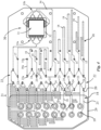
- the microfluidic network device comprises a plurality of reagent inlet channels fluidly connectable to reagent sources, at least one reagent outlet channel fluidly connected to the sampling device inlet distribution network, and a plurality of valves operable to selectively connect the inlet channels to the at least one outlet channel, wherein the sampling device and microfluidic network device are formed on a common microfluidic support as a single part.
- the support may for instance be in the form of a microscope slide for positioning under a microscope in the viewing field of a camera or other optical detection system for analysis of the sample reacted with the reagents.
- the microfluidic cartridge further comprises a reagent reservoir body (formed in the microfluidic support containing a plurality of wells configured to be filled with reagents, wherein each well is fluidly connected to a corresponding inlet channel.
- a reagent reservoir body formed in the microfluidic support containing a plurality of wells configured to be filled with reagents, wherein each well is fluidly connected to a corresponding inlet channel.
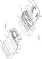
- the sampling device comprises a first arrangement of reagents distribution comprising inlet and outlet distribution networks arranged on two opposite sides of the microfluidic chamber and configured to direct flow of reagent(s) inside the microfluidic chamber along a first direction, and a second arrangement of reagents distribution comprising inlet and outlet distribution networks arranged on two other opposite sides of the microfluidic chamber and configured to direct flow of reagent(s) inside the microfluidic chamber in a second direction transverse to the first direction.
- the onboard reagent reservoir body is positioned adjacent a second end of the microfluidic support opposite the first end.
- four distribution networks can be arranged according to a configuration using flow-directing valves on the cartridge, where the sampling device comprises three inlet distribution networks used to introduce reagents to the microfluidic chamber and one outlet distribution network used for collecting fluids from the microfluidic chamber 31.
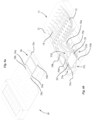
- the microfluidic cartridge operating system of the biological sample processing system further comprises an external reagent interfacing assembly comprising a reagent delivery manifold head 55 operably connected to external sources of reagents.
- the reagent delivery manifold head 55 comprises a plurality of reagent delivery lines 56 containing each a sealing, for instance in the form of an O-ring 57, disposed around the outlet portion of the delivery lines.
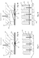
- the sealing may also be provided in the form of a gasket, similar to the configuration of figure 10 , between the manifold head 55 and the microfluidic support 12.
- the delivery lines 56 of the reagent manifold head 55 are therefore configured to be sealingly coupled to the corresponding reagent inlet couplings 16a of the external reagent inlet section 16 of the microfluidic cartridge 10.
- the microfluidic cartridge operating system also comprises a clamping actuator 41 configured to apply a clamping force against the sample support (e.g. a standard microscope slide) to form an airtight microfluidic chamber for sample processing.
- a clamping actuator 41 configured to apply a clamping force against the sample support (e.g. a standard microscope slide) to form an airtight microfluidic chamber for sample processing.
- the force applied by each manifold head against the corresponding sections of the microfluidic cartridge 10 may therefore be fine-tuned by adjusting the force applied by the piston driven mechanism when the microfluidic cartridge 10 is in contact with the different manifold heads and the force applied by the compression springs of each manifold head.
Landscapes
- Chemical & Material Sciences (AREA)
- Health & Medical Sciences (AREA)
- Dispersion Chemistry (AREA)
- Analytical Chemistry (AREA)
- Clinical Laboratory Science (AREA)
- Chemical Kinetics & Catalysis (AREA)
- General Health & Medical Sciences (AREA)
- Hematology (AREA)
- Automatic Analysis And Handling Materials Therefor (AREA)
Claims (16)
- Mikrofluidische Kartusche (10), die eine Probenentnahmevorrichtung (30), die einen Dichtungsring (32) aufweist, der eingerichtet ist, um eine mikrofluidische Kammer (31) zu bilden, wenn eine Halterung, die die eine daran fixierte biologische Probe enthält, mit dem Dichtungsring in Kontakt gebracht wird, und eine mikrofluidische Netzwerkvorrichtung (13) umfasst, die dazu ausgestaltet ist, der mikrofluidischen Kammer Reagenzien zuzuführen,wobei die Probenentnahmevorrichtung ferner Einlass- und Auslassverteilungsnetzwerke (33a, 33b) in Fluidverbindung mit der mikrofluidischen Kammer und einen Objektträgerhalter (35) zum Führen und Positionieren der Halterung, die eine mikrobiologische Probe enthält, auf der Probenentnahmevorrichtung umfasst,wobei die mikrofluidische Netzwerkvorrichtung eine Vielzahl von Reagenzeinlasskanälen (18), die fluidisch mit Reagenzquellen verbindbar sind, mindestens einen Reagenzauslasskanal (22), der fluidisch mit dem Probenentnahmevorrichtungseinlassverteilungsnetzwerk (33a) verbunden ist, und eine Vielzahl von Ventilen (25) umfasst, die betriebsfähig sind, um die Einlasskanäle selektiv mit dem mindestens einen Auslasskanal zu verbinden,wobei die Probenentnahmevorrichtung (30) und die mikrofluidische Netzwerkvorrichtung (13) auf einer gemeinsamen mikrofluidischen Halterung (12) als ein einziges Teil gebildet sind.
- Mikrofluidische Kartusche nach dem vorhergehenden Anspruch, ferner umfassend einen Reagenzbehälterkörper (29), der in der mikrofluidischen Halterung gebildet ist und eine Vielzahl von Mulden (29a) enthält, die dazu ausgestaltet sind, mit Reagenzien gefüllt zu werden, wobei jede Mulde (29a) fluidisch mit einem entsprechenden Einlasskanal (18) verbunden ist.
- Mikrofluidische Kartusche nach einem der vorhergehenden Ansprüche, wobei die Probenentnahmevorrichtung (30) eine erste Anordnung von Reagenzienverteilung umfasst, die Einlass- und Auslassverteilungsnetzwerke (33a, 33b), die auf zwei entgegengesetzten Seiten der mikrofluidischen Kammer (31) angeordnet sind und dazu ausgestaltet sind, Strömung von Reagenz/ien innerhalb der mikrofluidischen Kammer entlang einer ersten Richtung zu leiten, und eine zweite Anordnung von Reagenzienverteilung umfasst, die Einlass- und Auslassverteilungsnetzwerke (33c, 33d) umfasst, die auf zwei anderen entgegengesetzten Seiten der mikrofluidischen Kammer eingerichtet sind und dazu ausgestaltet sind, Strömung von Reagenz/ien innerhalb der mikrofluidischen Kammer (31) in einer zweiten Richtung quer zur ersten Richtung zu leiten.
- Mikrofluidische Kartusche nach einem der vorhergehenden Ansprüche, wobei die mikrofluidische Halterung eine einteilig gebildete geformte mikrofluidische Kunststoffplatte umfasst, in der die Einlasskanäle, der Auslasskanal und Probenentnahmevorrichtungseinlass- und - auslassverteilungskanäle gebildet sind.
- Mikrofluidische Kartusche nach einem der vorhergehenden Ansprüche, wobei der mindestens eine Reagenzauslasskanal (22) ein gemeinsamer einziger Auslasskanal ist, der mit einer Vielzahl von den Reagenzeinlasskanälen verbunden ist, wobei der Auslasskanal Ventilabschnitte (23) und Zwischenabschnitte (24) dazwischen umfasst, wobei die Ventilabschnitte (23) benachbart zu den Auslassendabschnitten (20) der Einlasskanäle (18) sind und die Zwischenabschnitte (24) fluidisch in Reihe miteinander verbunden sind, und wobei jedes der Vielzahl von Ventilen (25) einen Auslassendabschnitt (20) von jedem Einlasskanal mit einem entsprechenden Ventilabschnitt (23) des gemeinsamen Reagenzauslasskanals zusammenschaltet, wobei jedes Ventil zwischen einer geschlossenen Ventilposition, in der Fluidverbindung zwischen einem entsprechenden Einlasskanal und dem gemeinsamen Reagenzauslasskanal geschlossen ist, und einer geöffneten Ventilposition schaltbar ist, in der Fluidverbindung zwischen dem Einlasskanal und dem gemeinsamen Reagenzauslasskanal geöffnet ist.
- Mikrofluidische Kartusche nach einem der vorhergehenden Ansprüche, wobei die mikrofluidische Netzwerkvorrichtung (13) ferner eine äußere Reagenzeinlasssektion (16) umfasst, die mehrere Reagenzeinlasskopplungen (16a) zum fluidischen Koppeln eines oder mehrerer äußerer Reagenzeinlasskanäle (18) mit äußeren Reagenzquellen umfasst.
- Mikrofluidische Kartusche nach einem der vorhergehenden Ansprüche, wobei die Probenentnahmevorrichtung (30) benachbart zu einem ersten Ende der mikrofluidischen Halterung positioniert ist.
- Mikrofluidische Kartusche nach einem der vorhergehenden Ansprüche, wobei die mikrofluidische Netzwerkvorrichtung ferner einen Kartuschenauslass (17), einen Kammerauslasskanal (34), der mit dem Auslassverteilungsnetzwerk (33b) der Probenentnahmevorrichtung (30) verbunden ist, und mindestens zwei Ventile umfasst, die dazu ausgestaltet sind, den Kammerauslasskanal (34) beziehungsweise den gemeinsamen Reagenzauslasskanal (22) mit dem Kartuschenauslass (17) fluidisch zusammenzuschalten, um die Reagenzreste, die während der Probenverarbeitungsschritte aus der mikrofluidischen Kammer (31) der Probenentnahmevorrichtung kommen, abzulassen oder Waschlösungen, die während eines Waschschritts durch den gemeinsamen Reagenzauslasskanal (22) umlaufen, abzulassen.
- Mikrofluidische Kartusche nach einem der vorhergehenden Ansprüche in Verbindung mit Anspruch 2, wobei die mikrofluidische Netzwerkvorrichtung (13) zumindest teilweise im Inneren der mikrofluidischen Platte (12) auf einer ersten Seite davon eingebettet ist, während der Dichtungsring (32) der Probenentnahmevorrichtung (30) und der eingebaute Behälterkörper (29) auf einer zweiten Seite der mikrofluidischen Platte entgegengesetzt zur ersten Seite montiert sind.
- Mikrofluidische Kartusche nach einem der vorhergehenden Ansprüche, wobei eine Ventilsektion (14) die Vielzahl von Ventilen (25) umfasst, wobei die Ventilsektion (14) eine ablenkbare Membranschicht (14a) umfasst, die auf der mikrofluidischen Platte (12) angeordnet ist.
- System zur Verarbeitung biologischer Proben, umfassend:eine mikrofluidische Kartusche (10) nach einem der vorhergehenden Ansprüche, undein Betriebssystem der mikrofluidischen Kartusche, das eine Kartuschenaufnahme (60), welche die mikrofluidische Kartusche (10) aufnimmt, eine Ventilschnittstellenanordnung (45) und eine Behälterkörper-Schnittstellenanordnung (50) umfasst, wobei die Ventilschnittstellenanordnung betriebsfähig ist, um jedes Ventil (25) selektiv zu betätigen, um eine Fluidverbindung zwischen einem entsprechenden Einlasskanal und dem Reagenzauslasskanal herzustellen.
- System zur Verarbeitung biologischer Proben nach Anspruch 11 mit einer mikrofluidischen Kartusche nach Anspruch 2, wobei die Behälterkörper-Schnittstellenanordnung betriebsfähig ist, um Strömung eines Reagenz von einer oder mehreren Mulden in die mikrofluidische Kammer (31) der Probenentnahmevorrichtung (30) auszulösen.
- System zur Verarbeitung biologischer Proben nach Anspruch 12, wobei die Behälterkörper-Schnittstellenanordnung einen Abgabeverteilerkopf (50) umfasst, der in Bezug auf die Kartuschenaufnahme (60) von einer Nicht-Betriebsausgestaltung zu einer Betriebsausgestaltung verlagerbar ist, in der die untere Seite des Verteilerkopfs gegen die obere Seite des Behälterkörpers (29) anliegt, wobei der Verteilerkopf eine Vielzahl von Betätigungsleitungen (51) umfasst, die angeordnet sind, um mit der Vielzahl von Mulden zu fluchten.
- System zur Verarbeitung biologischer Proben nach einem der vorhergehenden Ansprüche 11 bis 13, wobei die Ventilschnittstellenanordnung (45) und die Körperbehälter-Schnittstellenanordnung (50) in Fluidverbindung mit einer äußeren Druckquelle sind.
- System zur Verarbeitung biologischer Proben nach Anspruch 14, wobei die Ventilschnittstellenanordnung einen Druckabgabe-Verteilerkopf (45) umfasst, der in Bezug auf die Kartuschenaufnahme (60) von einer Nicht-Betriebsausgestaltung zu einer Betriebsausgestaltung verlagerbar ist, in der die untere Seite des Verteilerkopfs gegen die Ventilsektion oder mehrere Ventilsektionen der mikrofluidischen Netzwerkvorrichtung anliegt, wobei der Verteilerkopf eine Vielzahl von Betätigungskammern (46) und entsprechende Betätigungsleitungen (47) in Fluidverbindung mit jeder Betätigungskammer umfasst, wobei die Vielzahl von Betätigungskammern (46) derart angeordnet sind, dass jede Kammer die Ventileinlass- und -auslassöffnungen (26, 27) des entsprechenden Ventils umschließt, wobei der Druckabgabe-Verteilerkopf (45) betriebsfähig ist, um selektiv einen Unterdruck im Inneren von einer oder mehreren Betätigungskammern (46) zu erzeugen.
- System zur Verarbeitung biologischer Proben nach einem der vorhergehenden Ansprüche 11 bis 15, wobei die mikrofluidische Netzwerkvorrichtung ferner eine äußere Reagenzeinlasssektion (16) umfasst, die mehrere Reagenzeinlasskopplungen (16a) zum Koppeln eines oder mehrerer Einlasskanäle (18) mit äußeren Reagenzquellen umfasst, und wobei das Betriebssystem der mikrofluidischen Kartusche ferner eine äußere Reagenzschnittstellenanordnung umfasst, die einen Reagenzabgabe-Verteilerkopf (55) umfasst, der betriebsfähig mit äußeren Quellen von Reagenzien verbunden ist, wobei der Reagenzabgabe-Verteilerkopf eine Vielzahl von Reagenzabgabeleitungen (56) umfasst, die angeordnet sind, um dichtend an die entsprechenden Reagenzeinlasskopplungen (16a) montiert zu werden.
Applications Claiming Priority (2)
| Application Number | Priority Date | Filing Date | Title |
|---|---|---|---|
| EP17193351.8A EP3459632A1 (de) | 2017-09-26 | 2017-09-26 | Mikrofluidische kartusche mit eingebauter abtastvorrichtung |
| PCT/EP2018/075299 WO2019063375A1 (en) | 2017-09-26 | 2018-09-19 | MICROFLUIDIC CARTRIDGE WITH INTEGRATED SAMPLING DEVICE |
Publications (3)
| Publication Number | Publication Date |
|---|---|
| EP3687686A1 EP3687686A1 (de) | 2020-08-05 |
| EP3687686C0 EP3687686C0 (de) | 2024-12-11 |
| EP3687686B1 true EP3687686B1 (de) | 2024-12-11 |
Family
ID=59974185
Family Applications (2)
| Application Number | Title | Priority Date | Filing Date |
|---|---|---|---|
| EP17193351.8A Withdrawn EP3459632A1 (de) | 2017-09-26 | 2017-09-26 | Mikrofluidische kartusche mit eingebauter abtastvorrichtung |
| EP18769198.5A Active EP3687686B1 (de) | 2017-09-26 | 2018-09-19 | Mikrofluidische kartusche mit eingebauter abtastvorrichtung |
Family Applications Before (1)
| Application Number | Title | Priority Date | Filing Date |
|---|---|---|---|
| EP17193351.8A Withdrawn EP3459632A1 (de) | 2017-09-26 | 2017-09-26 | Mikrofluidische kartusche mit eingebauter abtastvorrichtung |
Country Status (6)
| Country | Link |
|---|---|
| US (1) | US11358145B2 (de) |
| EP (2) | EP3459632A1 (de) |
| JP (1) | JP7264885B2 (de) |
| CN (1) | CN111163867B (de) |
| AU (1) | AU2018339506B2 (de) |
| WO (1) | WO2019063375A1 (de) |
Families Citing this family (6)
| Publication number | Priority date | Publication date | Assignee | Title |
|---|---|---|---|---|
| CN112442441B (zh) * | 2019-09-04 | 2024-12-24 | 张家港万众一芯生物科技有限公司 | 一种汇流体结构及基因测序仪 |
| AU2020444140B2 (en) * | 2020-04-20 | 2024-06-27 | Mgi Tech Co., Ltd. | Fluid laying device, fluid laying method, fluid laying system, composite device, and fluid passage device |
| WO2022112450A1 (en) | 2020-11-25 | 2022-06-02 | Oxford NanoImaging Limited | Reagent cartridge and measurement devices incorporating such cartridges |
| CN117063071A (zh) * | 2021-03-17 | 2023-11-14 | 伊鲁米那有限公司 | 非接触式分配器组件以及相关系统和方法 |
| CN114755356B (zh) * | 2022-05-17 | 2024-05-07 | 江苏炫一科学仪器有限公司 | 一种微流板多路气体样品选择进样装置 |
| DE102022209415A1 (de) | 2022-09-09 | 2024-03-14 | Robert Bosch Gesellschaft mit beschränkter Haftung | Mikrofluidisches Ventil und mikrofluidische Vorrichtung |
Family Cites Families (15)
| Publication number | Priority date | Publication date | Assignee | Title |
|---|---|---|---|---|
| WO2004065010A2 (en) | 2003-01-21 | 2004-08-05 | Micronics Inc. | Method and system for microfluidic manipulation, amplification and analysis of fluids, for example, bacteria assays and antiglobulin testing |
| NZ564141A (en) | 2005-05-09 | 2011-02-25 | Theranos Inc | Two way communication system for monitoring an analyte |
| WO2007093939A1 (en) | 2006-02-13 | 2007-08-23 | Koninklijke Philips Electronics N.V. | Microfluidic device for molecular diagnostic applications |
| WO2008030433A2 (en) * | 2006-09-06 | 2008-03-13 | Canon U.S. Life Sciences, Inc. | Chip and cartridge design configuration for performing micro-fluidic assays |
| US8680026B2 (en) | 2008-05-09 | 2014-03-25 | Akonni Biosystems, Inc. | Flow cell device |
| US8354080B2 (en) | 2009-04-10 | 2013-01-15 | Canon U.S. Life Sciences, Inc. | Fluid interface cartridge for a microfluidic chip |
| TW201109653A (en) | 2009-07-06 | 2011-03-16 | Sony Corp | Microfluidic device |
| ES2578778T3 (es) | 2009-10-21 | 2016-08-01 | Biocartis Nv | Cartucho microfluídico con placa de interfaz neumática paralela |
| CN102062767B (zh) * | 2009-11-16 | 2013-02-27 | 中国科学院大连化学物理研究所 | 大气样品在线采样-富集-热脱附-色谱进样联用装置 |
| US8941062B2 (en) * | 2010-11-16 | 2015-01-27 | 1087 Systems, Inc. | System for identifying and sorting living cells |
| WO2012122379A2 (en) | 2011-03-08 | 2012-09-13 | Colorado State University Research Foundation | Microfluidic cytochemical staining system |
| CA2856304C (en) | 2011-04-20 | 2017-05-16 | Mesa Tech International, Inc. | Oscillating amplification reaction for nucleic acids |
| CA2902127C (en) | 2012-02-27 | 2021-08-10 | Ecole Polytechnique Federale De Lausanne (Epfl) | Sample processing device with detachable slide |
| KR102799732B1 (ko) * | 2014-05-27 | 2025-04-22 | 일루미나, 인코포레이티드 | 베이스 기구 및 제거 가능한 카트리지를 포함하는 생화학적 분석을 위한 시스템들 및 방법들 |
| CN106824006B (zh) * | 2017-02-16 | 2018-09-04 | 中国科学院半导体研究所 | 一种防止交叉污染的多试剂顺序进液装置 |
-
2017
- 2017-09-26 EP EP17193351.8A patent/EP3459632A1/de not_active Withdrawn
-
2018
- 2018-09-19 CN CN201880062860.4A patent/CN111163867B/zh active Active
- 2018-09-19 US US16/649,870 patent/US11358145B2/en active Active
- 2018-09-19 AU AU2018339506A patent/AU2018339506B2/en active Active
- 2018-09-19 WO PCT/EP2018/075299 patent/WO2019063375A1/en not_active Ceased
- 2018-09-19 JP JP2020517367A patent/JP7264885B2/ja active Active
- 2018-09-19 EP EP18769198.5A patent/EP3687686B1/de active Active
Also Published As
| Publication number | Publication date |
|---|---|
| AU2018339506A1 (en) | 2020-02-13 |
| JP7264885B2 (ja) | 2023-04-25 |
| EP3687686C0 (de) | 2024-12-11 |
| US20200269241A1 (en) | 2020-08-27 |
| EP3459632A1 (de) | 2019-03-27 |
| EP3687686A1 (de) | 2020-08-05 |
| CN111163867A (zh) | 2020-05-15 |
| JP2020535417A (ja) | 2020-12-03 |
| AU2018339506B2 (en) | 2023-03-30 |
| US11358145B2 (en) | 2022-06-14 |
| WO2019063375A1 (en) | 2019-04-04 |
| CN111163867B (zh) | 2023-02-28 |
Similar Documents
| Publication | Publication Date | Title |
|---|---|---|
| EP3687686B1 (de) | Mikrofluidische kartusche mit eingebauter abtastvorrichtung | |
| US7431884B2 (en) | Chemical assays | |
| US11325120B2 (en) | Specimen treatment chip, specimen treatment apparatus, and specimen treatment method | |
| US7482585B2 (en) | Testing chip and micro integrated analysis system | |
| US8778280B2 (en) | Microfluidic chips and assay systems | |
| AU2002223871A1 (en) | Microfluidic devices and methods for chemical assays | |
| WO2007052471A1 (ja) | マイクロリアクタおよびそれを用いた送液方法 | |
| US7820109B2 (en) | Testing chip and micro analysis system | |
| US8021629B2 (en) | Analyzer | |
| KR101891968B1 (ko) | 하이브리드 유전자칩 | |
| US20120216403A1 (en) | Loading element | |
| JP2006284451A (ja) | 検体中の標的物質を分析するためのマイクロ総合分析システム | |
| WO2022136248A1 (en) | Analysis system for testing a sample |
Legal Events
| Date | Code | Title | Description |
|---|---|---|---|
| STAA | Information on the status of an ep patent application or granted ep patent |
Free format text: STATUS: UNKNOWN |
|
| STAA | Information on the status of an ep patent application or granted ep patent |
Free format text: STATUS: THE INTERNATIONAL PUBLICATION HAS BEEN MADE |
|
| PUAI | Public reference made under article 153(3) epc to a published international application that has entered the european phase |
Free format text: ORIGINAL CODE: 0009012 |
|
| STAA | Information on the status of an ep patent application or granted ep patent |
Free format text: STATUS: REQUEST FOR EXAMINATION WAS MADE |
|
| 17P | Request for examination filed |
Effective date: 20200326 |
|
| AK | Designated contracting states |
Kind code of ref document: A1 Designated state(s): AL AT BE BG CH CY CZ DE DK EE ES FI FR GB GR HR HU IE IS IT LI LT LU LV MC MK MT NL NO PL PT RO RS SE SI SK SM TR |
|
| AX | Request for extension of the european patent |
Extension state: BA ME |
|
| RIN1 | Information on inventor provided before grant (corrected) |
Inventor name: CAPPI, GIULIA Inventor name: AMMANN, MARCO Inventor name: COMINO, MARTA Inventor name: JORIS, PIERRE Inventor name: DUPOUY, DIEGO Inventor name: EROGLU, DENIZ Inventor name: CIFTLIK, ATA TUNA |
|
| RAP1 | Party data changed (applicant data changed or rights of an application transferred) |
Owner name: LUNAPHORE TECHNOLOGIES SA |
|
| DAV | Request for validation of the european patent (deleted) | ||
| DAX | Request for extension of the european patent (deleted) | ||
| STAA | Information on the status of an ep patent application or granted ep patent |
Free format text: STATUS: EXAMINATION IS IN PROGRESS |
|
| 17Q | First examination report despatched |
Effective date: 20210212 |
|
| P01 | Opt-out of the competence of the unified patent court (upc) registered |
Effective date: 20230527 |
|
| GRAP | Despatch of communication of intention to grant a patent |
Free format text: ORIGINAL CODE: EPIDOSNIGR1 |
|
| STAA | Information on the status of an ep patent application or granted ep patent |
Free format text: STATUS: GRANT OF PATENT IS INTENDED |
|
| INTG | Intention to grant announced |
Effective date: 20240905 |
|
| GRAS | Grant fee paid |
Free format text: ORIGINAL CODE: EPIDOSNIGR3 |
|
| GRAA | (expected) grant |
Free format text: ORIGINAL CODE: 0009210 |
|
| STAA | Information on the status of an ep patent application or granted ep patent |
Free format text: STATUS: THE PATENT HAS BEEN GRANTED |
|
| AK | Designated contracting states |
Kind code of ref document: B1 Designated state(s): AL AT BE BG CH CY CZ DE DK EE ES FI FR GB GR HR HU IE IS IT LI LT LU LV MC MK MT NL NO PL PT RO RS SE SI SK SM TR |
|
| REG | Reference to a national code |
Ref country code: GB Ref legal event code: FG4D |
|
| REG | Reference to a national code |
Ref country code: CH Ref legal event code: EP |
|
| REG | Reference to a national code |
Ref country code: DE Ref legal event code: R096 Ref document number: 602018077514 Country of ref document: DE |
|
| REG | Reference to a national code |
Ref country code: IE Ref legal event code: FG4D |
|
| U01 | Request for unitary effect filed |
Effective date: 20241211 |
|
| P04 | Withdrawal of opt-out of the competence of the unified patent court (upc) registered |
Free format text: CASE NUMBER: APP_66855/2024 Effective date: 20241218 |
|
| U07 | Unitary effect registered |
Designated state(s): AT BE BG DE DK EE FI FR IT LT LU LV MT NL PT RO SE SI Effective date: 20241220 |
|
| PG25 | Lapsed in a contracting state [announced via postgrant information from national office to epo] |
Ref country code: HR Free format text: LAPSE BECAUSE OF FAILURE TO SUBMIT A TRANSLATION OF THE DESCRIPTION OR TO PAY THE FEE WITHIN THE PRESCRIBED TIME-LIMIT Effective date: 20241211 |
|
| PG25 | Lapsed in a contracting state [announced via postgrant information from national office to epo] |
Ref country code: ES Free format text: LAPSE BECAUSE OF FAILURE TO SUBMIT A TRANSLATION OF THE DESCRIPTION OR TO PAY THE FEE WITHIN THE PRESCRIBED TIME-LIMIT Effective date: 20241211 |
|
| PG25 | Lapsed in a contracting state [announced via postgrant information from national office to epo] |
Ref country code: NO Free format text: LAPSE BECAUSE OF FAILURE TO SUBMIT A TRANSLATION OF THE DESCRIPTION OR TO PAY THE FEE WITHIN THE PRESCRIBED TIME-LIMIT Effective date: 20250311 |
|
| PG25 | Lapsed in a contracting state [announced via postgrant information from national office to epo] |
Ref country code: GR Free format text: LAPSE BECAUSE OF FAILURE TO SUBMIT A TRANSLATION OF THE DESCRIPTION OR TO PAY THE FEE WITHIN THE PRESCRIBED TIME-LIMIT Effective date: 20250312 |
|
| PG25 | Lapsed in a contracting state [announced via postgrant information from national office to epo] |
Ref country code: RS Free format text: LAPSE BECAUSE OF FAILURE TO SUBMIT A TRANSLATION OF THE DESCRIPTION OR TO PAY THE FEE WITHIN THE PRESCRIBED TIME-LIMIT Effective date: 20250311 |
|
| PG25 | Lapsed in a contracting state [announced via postgrant information from national office to epo] |
Ref country code: SM Free format text: LAPSE BECAUSE OF FAILURE TO SUBMIT A TRANSLATION OF THE DESCRIPTION OR TO PAY THE FEE WITHIN THE PRESCRIBED TIME-LIMIT Effective date: 20241211 |
|
| PG25 | Lapsed in a contracting state [announced via postgrant information from national office to epo] |
Ref country code: PL Free format text: LAPSE BECAUSE OF FAILURE TO SUBMIT A TRANSLATION OF THE DESCRIPTION OR TO PAY THE FEE WITHIN THE PRESCRIBED TIME-LIMIT Effective date: 20241211 |
|
| PG25 | Lapsed in a contracting state [announced via postgrant information from national office to epo] |
Ref country code: IS Free format text: LAPSE BECAUSE OF FAILURE TO SUBMIT A TRANSLATION OF THE DESCRIPTION OR TO PAY THE FEE WITHIN THE PRESCRIBED TIME-LIMIT Effective date: 20250411 |
|
| PG25 | Lapsed in a contracting state [announced via postgrant information from national office to epo] |
Ref country code: SK Free format text: LAPSE BECAUSE OF FAILURE TO SUBMIT A TRANSLATION OF THE DESCRIPTION OR TO PAY THE FEE WITHIN THE PRESCRIBED TIME-LIMIT Effective date: 20241211 |
|
| PG25 | Lapsed in a contracting state [announced via postgrant information from national office to epo] |
Ref country code: CZ Free format text: LAPSE BECAUSE OF FAILURE TO SUBMIT A TRANSLATION OF THE DESCRIPTION OR TO PAY THE FEE WITHIN THE PRESCRIBED TIME-LIMIT Effective date: 20241211 |
|
| REG | Reference to a national code |
Ref country code: CH Ref legal event code: U11 Free format text: ST27 STATUS EVENT CODE: U-0-0-U10-U11 (AS PROVIDED BY THE NATIONAL OFFICE) Effective date: 20251001 |
|
| PGFP | Annual fee paid to national office [announced via postgrant information from national office to epo] |
Ref country code: GB Payment date: 20250929 Year of fee payment: 8 |
|
| PLBE | No opposition filed within time limit |
Free format text: ORIGINAL CODE: 0009261 |
|
| STAA | Information on the status of an ep patent application or granted ep patent |
Free format text: STATUS: NO OPPOSITION FILED WITHIN TIME LIMIT |
|
| U20 | Renewal fee for the european patent with unitary effect paid |
Year of fee payment: 8 Effective date: 20250929 |
|
| 26N | No opposition filed |
Effective date: 20250912 |
|
| PGFP | Annual fee paid to national office [announced via postgrant information from national office to epo] |
Ref country code: CH Payment date: 20251001 Year of fee payment: 8 |