EP3687449B1 - Flüssigkeitsgefüllte haptik für eine intraokularlinse - Google Patents
Flüssigkeitsgefüllte haptik für eine intraokularlinse Download PDFInfo
- Publication number
- EP3687449B1 EP3687449B1 EP18842745.4A EP18842745A EP3687449B1 EP 3687449 B1 EP3687449 B1 EP 3687449B1 EP 18842745 A EP18842745 A EP 18842745A EP 3687449 B1 EP3687449 B1 EP 3687449B1
- Authority
- EP
- European Patent Office
- Prior art keywords
- fluid
- haptic
- intraocular lens
- filled
- iol
- Prior art date
- Legal status (The legal status is an assumption and is not a legal conclusion. Google has not performed a legal analysis and makes no representation as to the accuracy of the status listed.)
- Active
Links
Images

Classifications
-
- A—HUMAN NECESSITIES
- A61—MEDICAL OR VETERINARY SCIENCE; HYGIENE
- A61F—FILTERS IMPLANTABLE INTO BLOOD VESSELS; PROSTHESES; DEVICES PROVIDING PATENCY TO, OR PREVENTING COLLAPSING OF, TUBULAR STRUCTURES OF THE BODY, e.g. STENTS; ORTHOPAEDIC, NURSING OR CONTRACEPTIVE DEVICES; FOMENTATION; TREATMENT OR PROTECTION OF EYES OR EARS; BANDAGES, DRESSINGS OR ABSORBENT PADS; FIRST-AID KITS
- A61F2/00—Filters implantable into blood vessels; Prostheses, i.e. artificial substitutes or replacements for parts of the body; Appliances for connecting them with the body; Devices providing patency to, or preventing collapsing of, tubular structures of the body, e.g. stents
- A61F2/02—Prostheses implantable into the body
- A61F2/14—Eye parts, e.g. lenses or corneal implants; Artificial eyes
- A61F2/16—Intraocular lenses
- A61F2/1694—Capsular bag spreaders therefor
-
- A—HUMAN NECESSITIES
- A61—MEDICAL OR VETERINARY SCIENCE; HYGIENE
- A61F—FILTERS IMPLANTABLE INTO BLOOD VESSELS; PROSTHESES; DEVICES PROVIDING PATENCY TO, OR PREVENTING COLLAPSING OF, TUBULAR STRUCTURES OF THE BODY, e.g. STENTS; ORTHOPAEDIC, NURSING OR CONTRACEPTIVE DEVICES; FOMENTATION; TREATMENT OR PROTECTION OF EYES OR EARS; BANDAGES, DRESSINGS OR ABSORBENT PADS; FIRST-AID KITS
- A61F2/00—Filters implantable into blood vessels; Prostheses, i.e. artificial substitutes or replacements for parts of the body; Appliances for connecting them with the body; Devices providing patency to, or preventing collapsing of, tubular structures of the body, e.g. stents
- A61F2/0077—Special surfaces of prostheses, e.g. for improving ingrowth
- A61F2002/0081—Special surfaces of prostheses, e.g. for improving ingrowth directly machined on the prosthetic surface, e.g. holes, grooves
-
- A—HUMAN NECESSITIES
- A61—MEDICAL OR VETERINARY SCIENCE; HYGIENE
- A61F—FILTERS IMPLANTABLE INTO BLOOD VESSELS; PROSTHESES; DEVICES PROVIDING PATENCY TO, OR PREVENTING COLLAPSING OF, TUBULAR STRUCTURES OF THE BODY, e.g. STENTS; ORTHOPAEDIC, NURSING OR CONTRACEPTIVE DEVICES; FOMENTATION; TREATMENT OR PROTECTION OF EYES OR EARS; BANDAGES, DRESSINGS OR ABSORBENT PADS; FIRST-AID KITS
- A61F2/00—Filters implantable into blood vessels; Prostheses, i.e. artificial substitutes or replacements for parts of the body; Appliances for connecting them with the body; Devices providing patency to, or preventing collapsing of, tubular structures of the body, e.g. stents
- A61F2/02—Prostheses implantable into the body
- A61F2/14—Eye parts, e.g. lenses or corneal implants; Artificial eyes
- A61F2/16—Intraocular lenses
- A61F2002/1681—Intraocular lenses having supporting structure for lens, e.g. haptics
- A61F2002/169—Surrounding optic
-
- A—HUMAN NECESSITIES
- A61—MEDICAL OR VETERINARY SCIENCE; HYGIENE
- A61F—FILTERS IMPLANTABLE INTO BLOOD VESSELS; PROSTHESES; DEVICES PROVIDING PATENCY TO, OR PREVENTING COLLAPSING OF, TUBULAR STRUCTURES OF THE BODY, e.g. STENTS; ORTHOPAEDIC, NURSING OR CONTRACEPTIVE DEVICES; FOMENTATION; TREATMENT OR PROTECTION OF EYES OR EARS; BANDAGES, DRESSINGS OR ABSORBENT PADS; FIRST-AID KITS
- A61F2/00—Filters implantable into blood vessels; Prostheses, i.e. artificial substitutes or replacements for parts of the body; Appliances for connecting them with the body; Devices providing patency to, or preventing collapsing of, tubular structures of the body, e.g. stents
- A61F2/02—Prostheses implantable into the body
- A61F2/14—Eye parts, e.g. lenses or corneal implants; Artificial eyes
- A61F2/16—Intraocular lenses
- A61F2002/1681—Intraocular lenses having supporting structure for lens, e.g. haptics
- A61F2002/16901—Supporting structure conforms to shape of capsular bag
-
- A—HUMAN NECESSITIES
- A61—MEDICAL OR VETERINARY SCIENCE; HYGIENE
- A61F—FILTERS IMPLANTABLE INTO BLOOD VESSELS; PROSTHESES; DEVICES PROVIDING PATENCY TO, OR PREVENTING COLLAPSING OF, TUBULAR STRUCTURES OF THE BODY, e.g. STENTS; ORTHOPAEDIC, NURSING OR CONTRACEPTIVE DEVICES; FOMENTATION; TREATMENT OR PROTECTION OF EYES OR EARS; BANDAGES, DRESSINGS OR ABSORBENT PADS; FIRST-AID KITS
- A61F2/00—Filters implantable into blood vessels; Prostheses, i.e. artificial substitutes or replacements for parts of the body; Appliances for connecting them with the body; Devices providing patency to, or preventing collapsing of, tubular structures of the body, e.g. stents
- A61F2/02—Prostheses implantable into the body
- A61F2/14—Eye parts, e.g. lenses or corneal implants; Artificial eyes
- A61F2/16—Intraocular lenses
- A61F2002/1681—Intraocular lenses having supporting structure for lens, e.g. haptics
- A61F2002/16902—Separable from intraocular lens
-
- A—HUMAN NECESSITIES
- A61—MEDICAL OR VETERINARY SCIENCE; HYGIENE
- A61F—FILTERS IMPLANTABLE INTO BLOOD VESSELS; PROSTHESES; DEVICES PROVIDING PATENCY TO, OR PREVENTING COLLAPSING OF, TUBULAR STRUCTURES OF THE BODY, e.g. STENTS; ORTHOPAEDIC, NURSING OR CONTRACEPTIVE DEVICES; FOMENTATION; TREATMENT OR PROTECTION OF EYES OR EARS; BANDAGES, DRESSINGS OR ABSORBENT PADS; FIRST-AID KITS
- A61F2/00—Filters implantable into blood vessels; Prostheses, i.e. artificial substitutes or replacements for parts of the body; Appliances for connecting them with the body; Devices providing patency to, or preventing collapsing of, tubular structures of the body, e.g. stents
- A61F2/02—Prostheses implantable into the body
- A61F2/14—Eye parts, e.g. lenses or corneal implants; Artificial eyes
- A61F2/16—Intraocular lenses
- A61F2002/1681—Intraocular lenses having supporting structure for lens, e.g. haptics
- A61F2002/16905—Having means on lens to reduce overall dimension of lens for insertion into small incision
-
- A—HUMAN NECESSITIES
- A61—MEDICAL OR VETERINARY SCIENCE; HYGIENE
- A61F—FILTERS IMPLANTABLE INTO BLOOD VESSELS; PROSTHESES; DEVICES PROVIDING PATENCY TO, OR PREVENTING COLLAPSING OF, TUBULAR STRUCTURES OF THE BODY, e.g. STENTS; ORTHOPAEDIC, NURSING OR CONTRACEPTIVE DEVICES; FOMENTATION; TREATMENT OR PROTECTION OF EYES OR EARS; BANDAGES, DRESSINGS OR ABSORBENT PADS; FIRST-AID KITS
- A61F2230/00—Geometry of prostheses classified in groups A61F2/00 - A61F2/26 or A61F2/82 or A61F9/00 or A61F11/00 or subgroups thereof
- A61F2230/0063—Three-dimensional shapes
- A61F2230/0065—Three-dimensional shapes toroidal, e.g. ring-shaped, doughnut-shaped
-
- A—HUMAN NECESSITIES
- A61—MEDICAL OR VETERINARY SCIENCE; HYGIENE
- A61F—FILTERS IMPLANTABLE INTO BLOOD VESSELS; PROSTHESES; DEVICES PROVIDING PATENCY TO, OR PREVENTING COLLAPSING OF, TUBULAR STRUCTURES OF THE BODY, e.g. STENTS; ORTHOPAEDIC, NURSING OR CONTRACEPTIVE DEVICES; FOMENTATION; TREATMENT OR PROTECTION OF EYES OR EARS; BANDAGES, DRESSINGS OR ABSORBENT PADS; FIRST-AID KITS
- A61F2250/00—Special features of prostheses classified in groups A61F2/00 - A61F2/26 or A61F2/82 or A61F9/00 or A61F11/00 or subgroups thereof
- A61F2250/0003—Special features of prostheses classified in groups A61F2/00 - A61F2/26 or A61F2/82 or A61F9/00 or A61F11/00 or subgroups thereof having an inflatable pocket filled with fluid, e.g. liquid or gas
-
- A—HUMAN NECESSITIES
- A61—MEDICAL OR VETERINARY SCIENCE; HYGIENE
- A61F—FILTERS IMPLANTABLE INTO BLOOD VESSELS; PROSTHESES; DEVICES PROVIDING PATENCY TO, OR PREVENTING COLLAPSING OF, TUBULAR STRUCTURES OF THE BODY, e.g. STENTS; ORTHOPAEDIC, NURSING OR CONTRACEPTIVE DEVICES; FOMENTATION; TREATMENT OR PROTECTION OF EYES OR EARS; BANDAGES, DRESSINGS OR ABSORBENT PADS; FIRST-AID KITS
- A61F2250/00—Special features of prostheses classified in groups A61F2/00 - A61F2/26 or A61F2/82 or A61F9/00 or A61F11/00 or subgroups thereof
- A61F2250/0004—Special features of prostheses classified in groups A61F2/00 - A61F2/26 or A61F2/82 or A61F9/00 or A61F11/00 or subgroups thereof adjustable
- A61F2250/0013—Special features of prostheses classified in groups A61F2/00 - A61F2/26 or A61F2/82 or A61F9/00 or A61F11/00 or subgroups thereof adjustable for adjusting fluid pressure
-
- A—HUMAN NECESSITIES
- A61—MEDICAL OR VETERINARY SCIENCE; HYGIENE
- A61F—FILTERS IMPLANTABLE INTO BLOOD VESSELS; PROSTHESES; DEVICES PROVIDING PATENCY TO, OR PREVENTING COLLAPSING OF, TUBULAR STRUCTURES OF THE BODY, e.g. STENTS; ORTHOPAEDIC, NURSING OR CONTRACEPTIVE DEVICES; FOMENTATION; TREATMENT OR PROTECTION OF EYES OR EARS; BANDAGES, DRESSINGS OR ABSORBENT PADS; FIRST-AID KITS
- A61F2250/00—Special features of prostheses classified in groups A61F2/00 - A61F2/26 or A61F2/82 or A61F9/00 or A61F11/00 or subgroups thereof
- A61F2250/0058—Additional features; Implant or prostheses properties not otherwise provided for
- A61F2250/006—Additional features; Implant or prostheses properties not otherwise provided for modular
- A61F2250/0063—Nested prosthetic parts
Definitions
- the present disclosure relates generally to intraocular lenses (IOL), and more specifically, to a fluid-filled haptic for an IOL.
- IOL intraocular lenses
- the human eye includes a cornea and a crystalline lens that are intended to focus light that enters the pupil of the eye onto the retina.
- the eye may exhibit various refractive errors which result in light not being properly focused upon the retina, and which may reduce visual acuity.
- Many interventions have been developed over the years to correct various ocular aberrations. These include spectacles, contact lenses, corneal refractive surgery, such as laser-assisted in situ keratomileusis (LASIK) or corneal implants, and intraocular lenses (IOLs).
- IOLs are also used to treat cataracts by replacing the natural diseased crystalline lens of the eye of a patient.
- LASIK laser-assisted in situ keratomileusis
- IOLs intraocular lenses
- IOLs are also used to treat cataracts by replacing the natural diseased crystalline lens of the eye of a patient.
- a conventional single piece IOL is inserted into the capsular bag of a patient to replace the natural crystalline lens.
- a typical IOL may shift, either rotationally or axially or in combination, within the capsular bag over time, which may negatively impact the patient's quality of vision.
- the exact location of the lens in the eye may determine the type and degree of refractive power achieved. Therefore, an exact position of the IOL in the eye is assumed when calculating a surgical plan for a patient. When the exact position of the IOL deviates from the surgical plan assumptions, refractive errors may be introduced, which is undesirable.
- IOLs may suffer from capsule opacification, which can lead to a loss of transparency and a decrease in the quality of vision.
- Other problems affected by traditional IOL designs may include, but are not limited, to folds in the capsular bag (striae) and fibrosis around the haptics of the IOL as well as the IOL itself.
- an IOL haptic and an IOL that includes the haptic and an optic as defined in claim 1. Further features are provided in the dependent claims. Arrangements outside the scope of the claims may also be described in the specification as background and to assist in understanding the invention.
- an IOL haptic includes a toroid portion having an outer diameter, an inner diameter, and an interior volume. The interior volume of the toroid portion may be configured to be filled with a fluid.
- the IOL haptic may further include a receiving feature on the inner diameter of the toroid portion for receiving an IOL optic.
- an IOL includes a haptic and an optic.
- the haptic may include a toroid portion having an outer diameter and an inner diameter and an interior volume configured to be filled with a fluid.
- the haptic may further include a receiving feature on the inner diameter of the toroid portion for receiving the optic, the optic configured to fit in the receiving feature when the IOL is implanted into an eye of a patient.
- a method for implanting an IOL includes inserting a haptic of the IOL into an aphakic eye of a patient, the haptic including a toroid portion having an outer diameter and an inner diameter and an interior volume configured to be filled with a fluid.
- the haptic further includes a receiving feature on the inner diameter of the toroid portion for receiving an IOL optic.
- the method further includes filling at least a portion of an interior volume with the fluid, and placing the IOL optic in a receiving feature.
- the present disclosure relates generally to a fluid-filled haptic for an IOL.
- the fluid-filled haptic for an IOL disclosed herein may be formed as a fluid-filled toroid that is implanted into the lens capsule and radially exerts pressure against the equator of the capsular bag when filled.
- the fluid-filled haptic for an IOL disclosed herein may further exert pressure against anterior portions and posterior portions of the capsular bag when filled, in order to aid in anchoring the fluid-filled haptic to the equator of the capsular bag for improved axial and rotational stability.
- the fluid-filled haptic for an IOL disclosed herein may further maintain a stable and open capsular bag that has been subject to anterior capsulectomy, such as by creation of an anterior capsulorhexis.
- the fluid-filled haptic for an IOL disclosed herein may also prevent capsular bag opacification, or other negative effects, by keeping the capsular bag open by applying a uniform force around the equator and the posterior capsule.
- the fluid-filled haptic for an IOL disclosed herein may be implemented as a two piece device comprising a toroid-shaped fluid-filled haptic that receives an IOL optic.
- the fluid-filled haptic for an IOL disclosed herein may accordingly facilitate postoperative exchange of the IOL optic without affecting the implantation of the fluid-filled haptic.
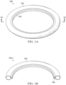
- FIGURES 1A and 1B illustrate an exemplary depiction of a fluid-filled haptic 100 for an IOL.
- FIGURES 1A and 1B are schematic diagrams for descriptive purposes and are not drawn to scale or perspective.
- a fluid-filled haptic 100 is shown including a toroid portion 102 and a receiving feature 104 for concentrically retaining an IOL optic (not shown in FIGURE 1A ) within toroid portion 102.
- fluid-filled haptic 100 is shown in a filled (or inflated) configuration that corresponds to a post-operative shape within the capsular bag of a patient.
- Receiving feature 104 is formed to enable retention of the IOL optic by fluid-filled haptic 100. As visible in the sectional view of a fluid-filled haptic 100-1 in FIGURE 1B , receiving feature 104 is shown formed as a circular V-groove that extends from a central inner surface of toroid portion 102. Although receiving feature 104 is shown as the V-groove extending around an entire inner circumference of toroid portion 102 in FIGURE 1A for descriptive purposes, it will be understood that receiving feature 104 may be formed using variously shaped structures and elements for retaining the IOL optic, and may be partially formed on the inner circumference, such that receiving feature 104 is absent at certain angular locations on the inner circumference of toroid portion 102.
- receiving feature 104 may be any one of : a V-groove, a C-groove, a C-channel, one or more magnetic anchors, among others.
- receiving feature 104 may be formed with a spring-loaded element (not shown) that secures the IOL optic in the receiving feature 104.
- the spring-loaded feature may result in an inner diameter of toroid portion 102 being smaller than an outer diameter of the IOL optic.
- fluid-filled haptic 100 may be injected by a surgeon into the capsular bag in a deflated or empty configuration, which may be suitable, for example, for injection using an injector with a narrow nozzle that can fit in a relatively small corneal incision. After the deflated fluid-filled haptic 100 is inserted into the capsular bag, fluid-filled haptic 100 may then be filled with a fluid to form the shape shown in FIGURE 1A .
- the fluid may be a gas, a liquid, a gel or various combinations thereof, among others.
- the surgeon may manipulate fluid-filled haptic 100 in order to place and position fluid-filled haptic 100 in a desired orientation within capsular bag, which may be easier to control and manipulate due to the decreased volume of fluid-filled haptic 100 prior to filling.
- the surgeon may pause and resume the intraoperative filling of fluid-filled haptic 100 in order to give the surgeon improved control during the procedure for precise placement of fluid-filled haptic 100 within the capsular bag.
- fluid-filled haptic 100 may have a filling port or a valve to enable filling and draining of the fluid, or components thereof, intraoperatively.
- receiving feature 104 may be formed of a material that is self-sealing when penetrated by a small injector needle, such as a syringe needle or a blunt needle or a cannula, among others, which are generically referred to herein as a "needle". Accordingly, receiving feature 104 may be formed with sufficient material at the inner circumference to enable self-sealing.
- a slit that can be penetrated by a needle may be formed on receiving feature 104 to facilitate filling and draining of the fluid.
- receiving feature 104 may be reaccessible to the surgeon to add or remove fluid, as desired, for example to titrate fluid into or out of fluid-filled haptic 100.
- the titration may involve fluid exchange or introduce another fluid or micro particles into toroid portion 102 of fluid-filled haptic 100.
- the fluid used to fill toroid portion 102 of fluid-filled haptic 100 may be a liquid, a gel, or multiple fluids that interact to result in desired properties.
- a curing agent or an ultraviolet (UV) sensitive material may be used.
- Certain microparticles may be introduced into the fluid for specific purposes, such as but not limited to a UV blocker, refractive index changing micro particles, among other microparticles.
- the fluid used to fill fluid-filled haptic 100 may be provided using separate components that are mixed for a desired effect.
- the fluid used to fill fluid-filled haptic 100 may be provided in two parts, such as a base component and a hardening or curing agent that results in increased stiffness or solidification upon mixing of the two parts, similar to the curing of an epoxy. Even when such a mixture is used for the fluid, fluid-filled haptic 100 may retain a certain degree of flexibility, and may remain more flexible during implantation, but after a certain amount of time the fluid may be cured to be more gel-like or to harden or to solidify to a desired degree, which may be controllable by the selection of the constituent components of the fluid and the mixing protocol.
- the hardening may occur as a result of one or more of: a curing/hardening time, a temperature, moisture, exposure to UV light, exposure to laser light, use of a catalyst, among others.
- toroid portion 102 of fluid-filled haptic 100 may be directly accessed, rather than using receiving portion 104 as a port, for example when toroid portion 102 is formed using a self-sealing material that enables the surgeon to penetrate through the self-sealing material to fill or drain the fluid or perform the titration techniques mentioned previously.
- a material used to form toroid portion 102 of fluid-filled haptic 100 may be flexible to a certain degree, so as to enable expansion and contraction, depending on an interior pressure of the fluid. Such flexibility may also result in an exterior circumferential diameter of toroid portion 102 increasing as the interior pressure of the fluid is increased. Depending on the design and configuration of toroid portion 102 and receiving feature 104, the flexibility may result in the interior circumferential diameter of toroid portion 102 increasing or decreasing as the interior pressure of the fluid is increased. When the interior circumferential diameter decreases with increasing interior pressure, similar to an inner tube of a tire, the circumferential pressure on the IOL optic may increase, which may stabilize the IOL optic in receiving feature 104.
- fluid-filled haptic 100 may fill the capsular bag towards the equator of the capsular bag, which may stabilize fluid-filled haptic 100 and the IOL optic by tight fitting within the capsular bag, which is desirable. Furthermore, because fluid-filled haptic 100 can be filled in a customized manner for each patient, the expansion of toroid portion 102 to adjust to the equator of the capsular bag enables fluid-filled haptic 100 to be accurately and snugly fitted to different sized capsular bags that occur in any human population, which improves the clinical applicability of fluid-filled haptic 100.
- fluid-filled haptic 100 may allow for a uniform force distribution against the entire equator of the capsular bag when fluid-filled haptic 100 is implanted, which is desirable because of the stabilizing effect for fluid-filled haptic 100 and the IOL optic.
- the uniform force distribution may also aid in preventing folds in the capsular bag (striae) due to the resulting tension in the capsular bag, which may evenly prevent folding.
- the action of fluid-filled haptic 100 to keep the capsular bag open by engaging with the capsular bag over the entire external circumference of fluid-filled haptic 100 may aid in prevention of posterior capsular opacification (PCO), also referred to as an "after-cataract".
- PCO posterior capsular opacification
- fluid-filled haptic 100 may have a sharpened or square-edged posterior edge (not shown) that engages with the capsular bag in order to improve PCO prevention.
- fluid-filled haptic 100 shown in FIGURE 1A may exhibit improved stability in the capsular bag because fluid-filled haptic 100 is anchored to the equator of the bag and may resist being pushed forward by the posterior capsular bag postoperatively, which may provide a high level of axial stability of fluid-filled haptic 100 and the IOL optic.
- the posterior capsular bag may tend to postoperatively collapse onto the conventional IOL.
- fluid-filled haptic 100 shown in FIGURE 1A may also be rotationally stable, because fluid-filled haptic 100 is in contact with the equator of the capsular bag over the entire external circumference of fluid-filled haptic 100, which resists undesired post operative rotation.
- Fluid-filled haptic 100 may also result in a separation between the anterior capsular bag and the posterior capsular bag due to the stability as a result of the uniform force distribution that holds the capsular bag in place.
- the separation between the anterior capsular bag and the posterior capsular bag, along with the mechanical contact of fluid-filled haptic 100 with various portions of the capsular bag, may aid in keeping the capsular bag open and may aid in preventing PCO of the capsular bag, such as a result of, but not limited to: enhanced endocapsular circulation of aqueous humor into the capsular bag, maintenance of a mechanical barrier to prevent cell migration into or out of the capsular bag, mechanical compression of the capsular bag (keeping the capsular bag pushed open), and maintenance of a postoperative contour of the capsular bag.
- fluid-filled haptic 100 may be implemented in a so-called "two-piece" implementation, of which one piece is fluid-filled haptic 100 while the second piece is the IOL optic (not shown in FIGURE 1A ).
- the two-piece implementation may facilitate a postoperative exchange of the IOL optic, for example, by preventing opacification of the capsular bag by fibrosis around the IOL optic and by providing a stabile setting of the implanted IOL optic.
- toroid portion 102 may aid in preventing opacification (or at least fibrosis) of the IOL optic, the IOL optic may be anchored solely using receiving feature 104 and may be otherwise freely accessible in the eye.
- the ease of accessibility of the IOL optic using fluid-filled haptic 100 may allow the surgeon to easily grab and manipulate the IOL optic both during the initial implantation and during a subsequent exchange of the IOL optic. Also, because of the decreased interior circumferential diameter of toroid portion 102, as compared with the diameter of the capsular bag, receiving feature 104 receives an IOL optic having a smaller diameter than the natural lens at the equator of the capsular bag. The reduced diameter of the IOL optic used with fluid-filled haptic 100 may enable the IOL optic to be easier to manipulate intraoperatively and easier to insert and remove from the eye, such as for a subsequent exchange of the IOL optic.
- toroid portion 102 may remain hollow (or unfilled) and may be formed using a flexible material that retains a desired shape upon implantation in the capsular bag. possible to have the outside haptic hollow and filled with something other than a liquid.
- toroid portion 102 may be preoperatively formed, or filled, with a desired agent having desired flexibility and mechanical properties.
- toroid portion 102 may be comprised of: a gel, an amorphous solid, an epoxy, a thermoplastic material, a composite material, among others and various combinations thereof.
- receiving feature 104 may receive various kinds of IOL optics used in ophthalmology.
- fluid-filled haptic 100 may be used with a non-foldable rigid IOL optic, such as comprising a polymethyl methacrylate (PMMA) lens.
- the IOL optic used with fluid-filled haptic 100 may be a flexible IOL optic, in which the optic zone may be comprised of various materials, such as silicone, hydrophobic acrylic, hydrophilic acrylic, hydrogel, collamer or combinations thereof.
- fluid-filled haptic 100 may also be comprised of various materials, such as polypropylene, PMMA, hydrophobic acrylic, hydrophilic acrylic, silicone or combinations thereof.
- the IOL optic may be placed within receiving feature 104 after injection into the eye.
- a measuring system may be used for guidance and verification of the position of fluid-filled haptic 100 and the IOL optic.
- an ORA TM System Alcon Laboratories Inc., Ft. Worth, Texas
- OCT optical coherence tomography
- UBM ultrasound biomicroscopy
- a so-called "one-piece" implementation of an IOL having fluid-filled haptic 100 and incorporating a fixed IOL optic is also contemplated.
- the one-piece implementation may provide the advantage of shorter and easier implantation effort, due to having a single injection of the IOL (instead of first injecting fluid-filled haptic 100 and then injecting the IOL optic in the two-piece case).
- one-piece implementations may reduce surgery time and cost.
- the IOL optic which would be a flexible IOL optic, may be attached using a given number of attachment points (similar to spokes on a wheel) to the interior circumference of toroid portion 102.
- both toroid portion 102 and the attached flexible IOL optic may be folded together and injected in a single step.
- the attachment points may be configured for removing the IOL optic subsequently in some implementations, such as by cutting through the attachment points. Because the IOL optic is already fixed to toroid portion 102 in the one-piece implementation, the operative step of placing the IOL optic in receiving feature 104 may be omitted.
- the one-piece implementation may still be equipped with receiving feature 104 to enable implantation of subsequent IOL optics.
- toroid portion 102 and the IOL optic may be tethered together and injected using the same injector, and then assembled intraoperatively.
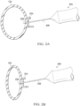
- FIGURE 2A a fluid-filled haptic 200 is shown above including toroid portion 102 and a receiving feature 204 for concentrically retaining an IOL optic (not shown in FIGURE 1A ) within toroid portion 102.
- FIGURE 2A is a schematic diagram for descriptive purposes and is not drawn to scale or perspective.
- FIGURE 2A is a sectional view with receiving feature 204 implemented as a C-groove that is self-sealing when a needle 206 penetrates receiving feature 204.
- a needle tip 208 is shown penetrating receiving feature 204 to enable filling of toroid portion 102 with a desired fluid, as described above.
- the filling of toroid portion 102 shown with fluid-filled haptic 200 may be performed intraoperatively, as desired to fill or inflate toroid portion 102 to a desired fill level or internal pressure.
- FIGURE 2B a fluid-filled haptic 201 is shown depicting how needle tip 208 may be used when toroid portion 102 is deflated or evacuated.
- FIGURE 2B is a sectional view with receiving feature 204 implemented as a C-groove that is self-sealing when a needle 206 penetrates receiving feature 204.
- fluid-filled haptic 201 may be placed in an injector and injected into the eye, as shown in FIGURE 2B .
- fluid-filled haptic 201 may be deflated or evacuated intraoperatively using needle 206 to remove the fluid that was previously filled in toroid portion 102.
- receiving feature 104/204 has been depicted and described as including a recess for receiving and retaining the IOL optic
- the present disclosure contemplates that the IOL optic may be received or retained using any suitable receiving or retaining feature that may physically engage and retain the IOL optic in a particular position within toroid portion 102.
- the receiving or retaining feature of toroid portion 102 may include a protrusion (not shown) that mates with a corresponding recess formed in the IOL optic to hold the IOL optic in place.
- the receiving or retaining feature may include a spring mechanism that exerts a force against the IOL optic when the IOL optic is placed in position within toroid portion 102, to hold the IOL optic in place.
- the interior surface of toroid portion 102 may include a leaf spring or a leaf clip that is fixed at one end and provides radial compression of the IOL optic at the other end, and remains disposed between the IOL optic and the interior surface of torioid portion 102 when the IOL optic is installed to hold the IOL optic in place. It will be understood that various features and retaining mechanisms for the IOL optic may be combined or selected as desired in particular implementations.
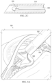
- FIGURE 2C an example of fluid-filled haptic 100 placed in an injector casing 310 shows how an IOL 306 with a fluid-filled haptic may be preloaded into the injector.
- IOL 306 is loaded into an injector casing 310 with a fluid line 308 attached, depicting an alternate implementation to the fluid-filling shown in FIGURES 2A and 2B . After filling, fluid line 308 may be removed intraoperatively.
- FIGURE 3A an injection 300 of an IOL 306 with a fluid-filled haptic is depicted.
- IOL 306 is shown being injected into a capsular bag 304 of an eye of a patient using an injector 302.
- the injector penetrates the cornea at an incision made for the surgical procedure, which may be as small as 2mm in length.
- IOL 306 is folded over for injection and may represent the two-piece embodiment with fluid-filled haptic 100 shown being injected first, which is followed by the injection of the IOL optic (not shown).
- FIGURE 3B an implant 301 of IOL 306 with a fluid-filled haptic is depicted postoperatively in capsular bag 304 of the eye of the patient.
- an IOL optic 312 is shown placed within a receiving feature 314 of IOL 306, depicting how IOL 306 is postoperatively immobilized within capsular bag 304.
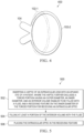
- a fluid-filled haptic 400 for an IOL is shown in cross-section having a receiving feature 104 that is a V-groove.
- a first toroid portion 102-1 shows a cross-section with little or no filling of the fluid
- a second toroid portion 102-2 shows how the shape of the cross-section changes with more or increased filling of the fluid.
- the change in cross-sectional shape of toroid portion 102 in FIGURE 4 shows how fluid-filled haptic 400 can be fitted into capsular bag 304 individually for each patient using fluid filling.
- FIGURE 5 a flow chart of selected elements of an embodiment of a method 500 for implanting an IOL having a fluid-filled haptic, as disclosed herein. It is noted that certain operations described in method 500 may be optional or may be rearranged in different embodiments.
- Method 500 may begin, at step 502, by inserting a haptic of an IOL into an aphakic eye of a patient, where the haptic further includes a toroid portion having an outer diameter, an inner diameter, and an interior volume configured to be filled with a fluid, and a receiving feature on the inner diameter of the toroid portion for receiving an IOL optic.
- the IOL optic is placed in the receiving feature.
- the receiving feature may be formed as a groove on at least a portion of the inner radius, the groove corresponding in size to a circumferential diameter of the IOL optic and extending circumferentially over at least a portion of the inner diameter, while placing the IOL optic in the receiving feature may further include placing the IOL optic in the groove.
- filling at least a portion of the interior volume with the fluid may further include penetrating the receiving feature using a needle to enable the interior volume to be filled with the fluid using the needle, where the receiving feature is self-sealing to the fluid when the needle is removed.
- inserting the haptic of the IOL into the aphakic eye of the patient may further include folding the toroid portion and the receiving feature in an injector, and using the injector to inject the haptic into the aphakic eye.
- filling at least a portion of the interior volume with the fluid may further include filling the interior volume with the fluid until the outer diameter of the toroid portion circumferentially fits an equator of a capsular bag of the aphakic eye.
- placing the IOL optic in the receiving feature may further include using a measuring instrument to determine a position of the toroid portion in the eye, and selecting the IOL optic based on the position of the toroid portion. Specifically, the measuring instrument may be used to determine or measure an exact position of the receiving feature, since the position of the receiving feature would be determinative for the postoperative position of the IOL optic.
- an IOL utilizes a haptic formed as a toroid portion configured to fit into a capsular bag of an aphakic eye of a patient.
- the toroid portion may be separate from an IOL optic and may include a receiving feature for the IOL optic.
- the toroid portion may be configured for intraoperative fluid-filling for snug fitting at the equator of the capsular bag, in order to immobilize the IOL optic.
Landscapes
- Health & Medical Sciences (AREA)
- Ophthalmology & Optometry (AREA)
- Cardiology (AREA)
- Oral & Maxillofacial Surgery (AREA)
- Transplantation (AREA)
- Engineering & Computer Science (AREA)
- Biomedical Technology (AREA)
- Heart & Thoracic Surgery (AREA)
- Vascular Medicine (AREA)
- Life Sciences & Earth Sciences (AREA)
- Animal Behavior & Ethology (AREA)
- General Health & Medical Sciences (AREA)
- Public Health (AREA)
- Veterinary Medicine (AREA)
- Prostheses (AREA)
Claims (13)
- Intraokularlinsenhaptik (100, 200), umfassend:einen Toroidabschnitt (102) mit einem Außendurchmesser und einem Innendurchmesser sowie einem Innenvolumen, wobei das Innenvolumen des Toroidabschnitts dazu ausgelegt ist, mit einem Fluid gefüllt zu werden; undein Aufnahmemerkmal (104, 204), das sich von einer zentralen Innenfläche des Toroidabschnitts (102) erstreckt; undwobei das Aufnahmemerkmal dazu ausgelegt ist, eine Intraokularlinsenoptik konzentrisch zu halten.
- Intraokularlinsenhaptik nach Anspruch 1, wobei das Aufnahmemerkmal (104, 204) einen ersten Abschnitt und einen zweiten Abschnitt umfasst, die sich von der Innenfläche des Toroidabschnitts (102) erstrecken und eine Nut auf mindestens einem Abschnitt der Innenfläche des Toroidabschnitts bilden, wobei die Nut in ihrer Größe einem Umfangsdurchmesser der Intraokularlinsenoptik entspricht.
- Intraokularlinsenhaptik nach Anspruch 2, wobei sich die Nut in Umfangsrichtung um den Innendurchmesser erstreckt.
- Intraokularlinsenhaptik nach Anspruch 1, wobei das Aufnahmemerkmal (104, 204) ein selbstdichtendes Material umfasst, so dass das Aufnahmemerkmal (104, 204) dazu ausgelegt ist, sich selbst abzudichten, wenn es von einer Nadel durchstochen wird, um zu ermöglichen, dass das Innenvolumen unter Verwendung der Nadel mit dem Fluid gefüllt wird, und gegenüber dem Fluid, wenn die Nadel entfernt wird.
- Intraokularlinsenhaptik nach Anspruch 1, wobei der Außendurchmesser des Toroidabschnitts (102) dazu ausgelegt ist, in Umfangsrichtung einem Äquator eines Kapselsacks zu entsprechen, wenn das Innenvolumen mit dem Fluid gefüllt ist.
- Intraokularlinse, umfassend:
eine Intraokularlinsenhaptik (100, 200) nach Anspruch 1 und ferner umfassend:
eine Intraokularlinsenoptik (312), die dazu ausgelegt ist, in das Aufnahmemerkmal (104, 204) zu passen, wenn die Intraokularlinse in ein Auge eines Patienten implantiert wird. - Intraokularlinse nach Anspruch 6, wobei das Aufnahmemerkmal (104, 204) einen ersten Abschnitt und einen zweiten Abschnitt umfasst, die sich von der Innenfläche des Toroidabschnitts erstrecken und eine Nut auf mindestens einem Abschnitt der Innenfläche des Toroidabschnitts bilden, wobei die Nut in ihrer Größe einem Umfangsdurchmesser der Intraokularlinsenoptik entspricht und sich in Umfangsrichtung über mindestens einen Abschnitt der Innenfläche erstreckt.
- Intraokularlinse nach Anspruch 6, wobei das Aufnahmemerkmal (104, 204) ein selbstdichtendes Material umfasst, so dass das Aufnahmemerkmal (104, 204) dazu ausgelegt ist, sich selbst abzudichten, wenn es von einer Nadel durchstochen wird, um zu ermöglichen, dass das Innenvolumen unter Verwendung der Nadel mit dem Fluid gefüllt wird, und gegenüber dem Fluid, wenn die Nadel entfernt wird.
- Intraokularlinse nach Anspruch 6, wobei der Außendurchmesser des Toroidabschnitts dazu ausgelegt ist, in Umfangsrichtung einem Äquator eines Kapselsacks zu entsprechen, wenn das Innenvolumen mit dem Fluid gefüllt ist.
- Intraokularlinse nach Anspruch 6, wobei die Intraokularlinsenoptik an dem Aufnahmemerkmal angebracht ist.
- Intraokularlinsenhaptik nach Anspruch 2, wobei die Nut eine V-förmige Nut umfasst.
- Intraokularlinsenhaptik nach Anspruch 1, wobei das Aufnahmemerkmal (104, 204) eine C-förmige Nut umfasst.
- Intraokularlinsenhaptik nach Anspruch 1, wobei das Aufnahmemerkmal (104, 204) ein federbelastetes Element umfasst.
Applications Claiming Priority (2)
| Application Number | Priority Date | Filing Date | Title |
|---|---|---|---|
| US201762608029P | 2017-12-20 | 2017-12-20 | |
| PCT/IB2018/060468 WO2019123391A1 (en) | 2017-12-20 | 2018-12-20 | Fluid-filled haptic for an intraocular lens |
Publications (2)
| Publication Number | Publication Date |
|---|---|
| EP3687449A1 EP3687449A1 (de) | 2020-08-05 |
| EP3687449B1 true EP3687449B1 (de) | 2025-06-25 |
Family
ID=65276237
Family Applications (1)
| Application Number | Title | Priority Date | Filing Date |
|---|---|---|---|
| EP18842745.4A Active EP3687449B1 (de) | 2017-12-20 | 2018-12-20 | Flüssigkeitsgefüllte haptik für eine intraokularlinse |
Country Status (4)
| Country | Link |
|---|---|
| US (2) | US11259915B2 (de) |
| EP (1) | EP3687449B1 (de) |
| JP (1) | JP7565796B2 (de) |
| WO (1) | WO2019123391A1 (de) |
Families Citing this family (3)
| Publication number | Priority date | Publication date | Assignee | Title |
|---|---|---|---|---|
| CN111481322B (zh) * | 2020-04-20 | 2022-02-15 | 西安眼得乐医疗科技有限公司 | 一种可调式囊内环 |
| CN111467077B (zh) * | 2020-04-20 | 2022-02-15 | 西安眼得乐医疗科技有限公司 | 一种用于先天性白内障的综合人工晶状体植入体 |
| US11357620B1 (en) * | 2021-09-10 | 2022-06-14 | California LASIK & Eye, Inc. | Exchangeable optics and therapeutics |
Family Cites Families (13)
| Publication number | Priority date | Publication date | Assignee | Title |
|---|---|---|---|---|
| JPS63267351A (ja) * | 1987-04-27 | 1988-11-04 | Canon Inc | 眼内レンズ |
| US4902293A (en) | 1989-04-13 | 1990-02-20 | Feaster Fred T | Intraocular lens with inflatable haptic |
| GR20000100291A (el) * | 2000-08-24 | 2002-05-24 | Σ. Χαριλαος Γκινης | Συμπιεστο εμφυτευμα για την αυξηση της οφθαλμικης ελαστικοτητας αι την προληψη των συσχετιζομενων με την ηλικια εκφυλιστικων παθησεων του οφθαλμου |
| CN1485015A (zh) | 2002-09-24 | 2004-03-31 | 林纯益 | 可自动调适的人工水晶体 |
| JP4927371B2 (ja) | 2005-09-28 | 2012-05-09 | 興和株式会社 | 眼内レンズ |
| KR100843454B1 (ko) | 2007-03-08 | 2008-07-03 | 박경진 | 안구내렌즈 지지체 |
| US8728158B2 (en) * | 2009-02-09 | 2014-05-20 | Jeffrey C. Whitsett | Exchangeable intraocular lens device and method of use |
| US8858626B2 (en) | 2009-02-10 | 2014-10-14 | Novartis Ag | Accommodative intraocular lens system |
| US10028824B2 (en) * | 2012-01-24 | 2018-07-24 | Clarvista Medical, Inc. | Modular intraocular lens designs, tools and methods |
| JP5475087B1 (ja) | 2012-11-01 | 2014-04-16 | 株式会社中京メディカル | 眼内移植物、眼内移植物セット、眼内レンズ |
| CN110946676B (zh) * | 2013-03-21 | 2023-02-17 | 施菲姆德控股有限责任公司 | 调节性人工晶状体 |
| CH711113A2 (de) * | 2015-05-21 | 2016-11-30 | Feusi Marco | Kapselspannring. |
| EP3383320A4 (de) * | 2015-12-01 | 2019-08-21 | Lensgen, Inc | Akkomodative intraokularlinsenvorrichtung |
-
2018
- 2018-12-20 EP EP18842745.4A patent/EP3687449B1/de active Active
- 2018-12-20 WO PCT/IB2018/060468 patent/WO2019123391A1/en not_active Ceased
- 2018-12-20 US US16/227,149 patent/US11259915B2/en active Active
- 2018-12-20 JP JP2020533055A patent/JP7565796B2/ja active Active
-
2022
- 2022-01-04 US US17/646,997 patent/US20220125576A1/en active Pending
Also Published As
| Publication number | Publication date |
|---|---|
| US20190183633A1 (en) | 2019-06-20 |
| US11259915B2 (en) | 2022-03-01 |
| EP3687449A1 (de) | 2020-08-05 |
| US20220125576A1 (en) | 2022-04-28 |
| WO2019123391A1 (en) | 2019-06-27 |
| JP2021507739A (ja) | 2021-02-25 |
| JP7565796B2 (ja) | 2024-10-11 |
Similar Documents
| Publication | Publication Date | Title |
|---|---|---|
| AU2024200032B2 (en) | Modular intraocular lens designs, tools and methods | |
| JP7457408B2 (ja) | 眼内偽水晶体コンタクトレンズならびに関連システムおよび方法 | |
| US8303654B2 (en) | Device for use in eye surgery | |
| EP2629698B1 (de) | Intraokulares linsensystem | |
| CN105744914B (zh) | 眼内晶状体组件 | |
| US20220125576A1 (en) | Fluid-filled haptic for an intraocular lens | |
| EP4606359A2 (de) | Ophthalmische vorrichtung zur arzneimittelabgabe | |
| JP6837125B2 (ja) | 嚢切開固定のためのスイベルハプティックを有する後方房眼内レンズ | |
| TR2023004277A1 (tr) | Katarak cerrahisinde efektif lens pozisyonunu sabitleyen ve cerrahi sonrası kalan refraktif hatanın düzeltilmesini sağlayan bir kapsül içi implant. |
Legal Events
| Date | Code | Title | Description |
|---|---|---|---|
| STAA | Information on the status of an ep patent application or granted ep patent |
Free format text: STATUS: UNKNOWN |
|
| STAA | Information on the status of an ep patent application or granted ep patent |
Free format text: STATUS: THE INTERNATIONAL PUBLICATION HAS BEEN MADE |
|
| PUAI | Public reference made under article 153(3) epc to a published international application that has entered the european phase |
Free format text: ORIGINAL CODE: 0009012 |
|
| STAA | Information on the status of an ep patent application or granted ep patent |
Free format text: STATUS: REQUEST FOR EXAMINATION WAS MADE |
|
| 17P | Request for examination filed |
Effective date: 20200430 |
|
| AK | Designated contracting states |
Kind code of ref document: A1 Designated state(s): AL AT BE BG CH CY CZ DE DK EE ES FI FR GB GR HR HU IE IS IT LI LT LU LV MC MK MT NL NO PL PT RO RS SE SI SK SM TR |
|
| AX | Request for extension of the european patent |
Extension state: BA ME |
|
| DAV | Request for validation of the european patent (deleted) | ||
| DAX | Request for extension of the european patent (deleted) | ||
| STAA | Information on the status of an ep patent application or granted ep patent |
Free format text: STATUS: EXAMINATION IS IN PROGRESS |
|
| 17Q | First examination report despatched |
Effective date: 20230224 |
|
| P01 | Opt-out of the competence of the unified patent court (upc) registered |
Effective date: 20230507 |
|
| GRAP | Despatch of communication of intention to grant a patent |
Free format text: ORIGINAL CODE: EPIDOSNIGR1 |
|
| STAA | Information on the status of an ep patent application or granted ep patent |
Free format text: STATUS: GRANT OF PATENT IS INTENDED |
|
| INTG | Intention to grant announced |
Effective date: 20240918 |
|
| GRAJ | Information related to disapproval of communication of intention to grant by the applicant or resumption of examination proceedings by the epo deleted |
Free format text: ORIGINAL CODE: EPIDOSDIGR1 |
|
| STAA | Information on the status of an ep patent application or granted ep patent |
Free format text: STATUS: EXAMINATION IS IN PROGRESS |
|
| GRAP | Despatch of communication of intention to grant a patent |
Free format text: ORIGINAL CODE: EPIDOSNIGR1 |
|
| STAA | Information on the status of an ep patent application or granted ep patent |
Free format text: STATUS: GRANT OF PATENT IS INTENDED |
|
| INTG | Intention to grant announced |
Effective date: 20250128 |
|
| GRAS | Grant fee paid |
Free format text: ORIGINAL CODE: EPIDOSNIGR3 |
|
| GRAA | (expected) grant |
Free format text: ORIGINAL CODE: 0009210 |
|
| STAA | Information on the status of an ep patent application or granted ep patent |
Free format text: STATUS: THE PATENT HAS BEEN GRANTED |
|
| AK | Designated contracting states |
Kind code of ref document: B1 Designated state(s): AL AT BE BG CH CY CZ DE DK EE ES FI FR GB GR HR HU IE IS IT LI LT LU LV MC MK MT NL NO PL PT RO RS SE SI SK SM TR |
|
| REG | Reference to a national code |
Ref country code: GB Ref legal event code: FG4D |
|
| REG | Reference to a national code |
Ref country code: CH Ref legal event code: EP |
|
| REG | Reference to a national code |
Ref country code: CH Ref legal event code: EP |
|
| REG | Reference to a national code |
Ref country code: IE Ref legal event code: FG4D |
|
| REG | Reference to a national code |
Ref country code: DE Ref legal event code: R096 Ref document number: 602018082985 Country of ref document: DE |
|
| REG | Reference to a national code |
Ref country code: NL Ref legal event code: FP |
|
| PG25 | Lapsed in a contracting state [announced via postgrant information from national office to epo] |
Ref country code: FI Free format text: LAPSE BECAUSE OF FAILURE TO SUBMIT A TRANSLATION OF THE DESCRIPTION OR TO PAY THE FEE WITHIN THE PRESCRIBED TIME-LIMIT Effective date: 20250625 |
|
| REG | Reference to a national code |
Ref country code: LT Ref legal event code: MG9D |
|
| PG25 | Lapsed in a contracting state [announced via postgrant information from national office to epo] |
Ref country code: GR Free format text: LAPSE BECAUSE OF FAILURE TO SUBMIT A TRANSLATION OF THE DESCRIPTION OR TO PAY THE FEE WITHIN THE PRESCRIBED TIME-LIMIT Effective date: 20250926 Ref country code: NO Free format text: LAPSE BECAUSE OF FAILURE TO SUBMIT A TRANSLATION OF THE DESCRIPTION OR TO PAY THE FEE WITHIN THE PRESCRIBED TIME-LIMIT Effective date: 20250925 |
|
| PG25 | Lapsed in a contracting state [announced via postgrant information from national office to epo] |
Ref country code: BG Free format text: LAPSE BECAUSE OF FAILURE TO SUBMIT A TRANSLATION OF THE DESCRIPTION OR TO PAY THE FEE WITHIN THE PRESCRIBED TIME-LIMIT Effective date: 20250625 |
|
| PG25 | Lapsed in a contracting state [announced via postgrant information from national office to epo] |
Ref country code: HR Free format text: LAPSE BECAUSE OF FAILURE TO SUBMIT A TRANSLATION OF THE DESCRIPTION OR TO PAY THE FEE WITHIN THE PRESCRIBED TIME-LIMIT Effective date: 20250625 |
|
| PG25 | Lapsed in a contracting state [announced via postgrant information from national office to epo] |
Ref country code: RS Free format text: LAPSE BECAUSE OF FAILURE TO SUBMIT A TRANSLATION OF THE DESCRIPTION OR TO PAY THE FEE WITHIN THE PRESCRIBED TIME-LIMIT Effective date: 20250925 |
|
| PG25 | Lapsed in a contracting state [announced via postgrant information from national office to epo] |
Ref country code: LV Free format text: LAPSE BECAUSE OF FAILURE TO SUBMIT A TRANSLATION OF THE DESCRIPTION OR TO PAY THE FEE WITHIN THE PRESCRIBED TIME-LIMIT Effective date: 20250625 |
|
| PG25 | Lapsed in a contracting state [announced via postgrant information from national office to epo] |
Ref country code: PT Free format text: LAPSE BECAUSE OF FAILURE TO SUBMIT A TRANSLATION OF THE DESCRIPTION OR TO PAY THE FEE WITHIN THE PRESCRIBED TIME-LIMIT Effective date: 20251027 |
|
| PGFP | Annual fee paid to national office [announced via postgrant information from national office to epo] |
Ref country code: NL Payment date: 20251126 Year of fee payment: 8 |
|
| REG | Reference to a national code |
Ref country code: AT Ref legal event code: MK05 Ref document number: 1805686 Country of ref document: AT Kind code of ref document: T Effective date: 20250625 |
|
| PG25 | Lapsed in a contracting state [announced via postgrant information from national office to epo] |
Ref country code: IS Free format text: LAPSE BECAUSE OF FAILURE TO SUBMIT A TRANSLATION OF THE DESCRIPTION OR TO PAY THE FEE WITHIN THE PRESCRIBED TIME-LIMIT Effective date: 20251025 |
|
| PGFP | Annual fee paid to national office [announced via postgrant information from national office to epo] |
Ref country code: DE Payment date: 20251119 Year of fee payment: 8 |
|
| PGFP | Annual fee paid to national office [announced via postgrant information from national office to epo] |
Ref country code: GB Payment date: 20251120 Year of fee payment: 8 |
|
| PG25 | Lapsed in a contracting state [announced via postgrant information from national office to epo] |
Ref country code: AT Free format text: LAPSE BECAUSE OF FAILURE TO SUBMIT A TRANSLATION OF THE DESCRIPTION OR TO PAY THE FEE WITHIN THE PRESCRIBED TIME-LIMIT Effective date: 20250625 Ref country code: SM Free format text: LAPSE BECAUSE OF FAILURE TO SUBMIT A TRANSLATION OF THE DESCRIPTION OR TO PAY THE FEE WITHIN THE PRESCRIBED TIME-LIMIT Effective date: 20250625 |
|
| PGFP | Annual fee paid to national office [announced via postgrant information from national office to epo] |
Ref country code: IT Payment date: 20251126 Year of fee payment: 8 |
|
| PGFP | Annual fee paid to national office [announced via postgrant information from national office to epo] |
Ref country code: FR Payment date: 20251124 Year of fee payment: 8 |
|
| PG25 | Lapsed in a contracting state [announced via postgrant information from national office to epo] |
Ref country code: CZ Free format text: LAPSE BECAUSE OF FAILURE TO SUBMIT A TRANSLATION OF THE DESCRIPTION OR TO PAY THE FEE WITHIN THE PRESCRIBED TIME-LIMIT Effective date: 20250625 |
|
| PG25 | Lapsed in a contracting state [announced via postgrant information from national office to epo] |
Ref country code: PL Free format text: LAPSE BECAUSE OF FAILURE TO SUBMIT A TRANSLATION OF THE DESCRIPTION OR TO PAY THE FEE WITHIN THE PRESCRIBED TIME-LIMIT Effective date: 20250625 |
|
| PG25 | Lapsed in a contracting state [announced via postgrant information from national office to epo] |
Ref country code: EE Free format text: LAPSE BECAUSE OF FAILURE TO SUBMIT A TRANSLATION OF THE DESCRIPTION OR TO PAY THE FEE WITHIN THE PRESCRIBED TIME-LIMIT Effective date: 20250625 |
|
| PG25 | Lapsed in a contracting state [announced via postgrant information from national office to epo] |
Ref country code: SK Free format text: LAPSE BECAUSE OF FAILURE TO SUBMIT A TRANSLATION OF THE DESCRIPTION OR TO PAY THE FEE WITHIN THE PRESCRIBED TIME-LIMIT Effective date: 20250625 |
|
| PG25 | Lapsed in a contracting state [announced via postgrant information from national office to epo] |
Ref country code: ES Free format text: LAPSE BECAUSE OF FAILURE TO SUBMIT A TRANSLATION OF THE DESCRIPTION OR TO PAY THE FEE WITHIN THE PRESCRIBED TIME-LIMIT Effective date: 20250625 |